Embed Size (px)
Citation preview
Shu-ren Wang i dr. Analiza loma i gubitka energije ploča od pješćenjaka podvrgnutih koncentriranom opterećenju
ISSN 1330-3651 (Print), ISSN 1848-6339 (Online) UDC/UDK 620.163.4:691.215
FRACTURE PROCESS AND ENERGY DISSIPATION ANALYSIS OF SANDSTONE PLATES UNDER THE CONCENTRATED LOAD Shu-ren Wang, Paul Hagan, Dian-fu Xu, Bao-wen Hu, Ze-cheng Li, Kanchana Gamage
Original scientific paper Under the concentrated load, the tests on the brittle fracture of hinged arching until the rock-arch instability of the double-layer rock plates were conducted using self-developed loading device, and the influence factors on the rock-arch structure failure were analyzed by a numerical test based on the particle flow code (PFC). The results showed that the force-displacement curves of the double-layer rock plates displayed four phases: the small deformation elastic stage, the brittle fracture arching stage, the rock-arch structure bearing load stage and the rock-arch structure instability stage. The friction coefficient effect, cohesive strength effect of the layer between the two rock plates, and the size effect of the rock plate thickness were analyzed also. The numerical test results showed that the strain energy and strain energy entropy were consistent with the fracture instability process of the double-layer rock plates, which demonstrated that the strain energy entropy could characterize the steady state of the whole system of the double-layer rock plates. Keywords: fracture, hinged rock-arch, instability, sandstone plates, strain energy entropy Analiza loma i gubitka energije ploča od pješćenjaka podvrgnutih koncentriranom opterećenju
Izvorni znanstveni članak Provedena su ispitivanja krtog loma zglobnog luka pri koncentriranom opterećenju sve do nestabilnosti kamenog luka dvoslojnih kamenih ploča primjenom uređaja za opterećenje vlastite proizvodnje, i analizirani su čimbenici koji djeluju na lom konstrukcije kamenog luka primjenom numeričkog testa zasnovanog na kodu toka čestica (PFC - particle flow code). Rezultati su pokazali da su dijagrami sila-pomak kod dvoslojnih kamenih ploča rezultirali s četiri faze: elastični stadij male deformacije, stadij krtog loma luka, stadij izdržljivosti opterećenja konstrukcije kamenog luka te stadij nestabilnosti kamenog luka. Analizirali su se i utjecaj faktora trenja, utjecaj kohezijske čvrstoće sloja između dvije kamene ploče i utjecaj debljine kamenih ploča. Rezultati numeričkog ispitivanja pokazali su da su energija deformacije i entropija energije deformacije u skladu s procesom nestabilnosti loma dvoslojnih kamenih ploča, što je pokazalo da entropija energije deformacije može karakterizirati stacionarno stanje čitavog sustava dvoslojnih kamenih ploča. Ključne riječi: entropija energije deformacije, lom, nestabilnost, ploče od pješćenjaka, zglobni kameni luk 1 Introduction
There are obvious characteristics of the layered rock structure in the coal-bearing strata, so it is of important theoretical significance and practical value to study the deformation and fracture characteristics of the layered roof in mining field considering the layers interaction.
It is the main topic all the time for home and abroad scholars to research on the instability of the rock roof in the mining field. For example, D. L. Zhang et al. established a mechanical model of combination system for rock mass with the interlayer, and analyzed the failure and instability mechanism of rock mass with the interlayer [1]. H. W. Wang et al. analyzed the fracture instability characteristics of the roof under different mining distances in the mining work face [2]. W. T. Li et al. researched on the deformation and failure mechanism of deep roadway with intercalated coal seam in roof [3]. Y. Yang et al. put forward the mechanical model of the thick-hard rock layers and analyses of the model’s features [4]. J. A. Wang analyzed the rheological failure characteristics of the roof in the mined-out areas through combining the thin plate and rheology theories [5]. Y. Pan had conducted the analytical analysis of the variation trend of the bending moment, the deflection and the shear force of the hard roof in the mining field [6]. P. P. Nomiko researched the mechanical response of the multi-jointed roof beams using two dimensional distinct element code [7]. D. B. Mazor examined the arching mechanism of the blocky rock mass deformation after the underground tunnel being excavated using the discrete element method [8], and the related studies [9, 10], etc.
In the thermodynamics, the entropy is a physical quantity to be used to describe the degree of disorder or the uniformity of energy distribution of the system. Now the concept of entropy is widely used in the fields of classical statistical mechanics, ecology and economy, and some mature theories have been formed [11, 12]. So the strain energy entropy can be defined to describe the stress state change of the layered roof system in the mining field [13].
In summary, though many research achievements have been made, only a few researchers researched on the macro-mechanical response of the rock plates considering the layer effect, and did not further explore the microscopic damage of the rock plates. Therefore, a new loading device was developed to study the rock-arch instability characteristics of the rock plates, and particle flow code (PFC) was used to further probe into the microscopic damage of the double-layer rock plates under the concentrated load. 2 Instability experiment on double-layer rock plates 2.1 Sandstone plates
The rock plate samples in the test were Hawkesbury sandstone, which was obtained from Gosford Quarry in Sydney, Australia [14]. According to the definition of the thin plate and thick plate in elastic mechanics, the specimen size of the thick plate was designed to 190 mm × 75 mm × 24 mm (length × width × thickness) and that of the thin plate was designed to 190 mm × 75 mm ×14 mm (length × width × thickness) [15]. Double-layer sandstone plates of four groups were as such combination,
Tehnički vjesnik 21, 6(2014), 1345-1351 1345
Fracture process and energy dissipation analysis of sandstone plates under the concentrated load Shu-ren Wang et al.
upper thin and lower thick plates, upper thick and lower thin plates, two thick plates, and two thin plates. Each group of sandstone samples was prepared for at least six plates.
2.2 Loading equipment
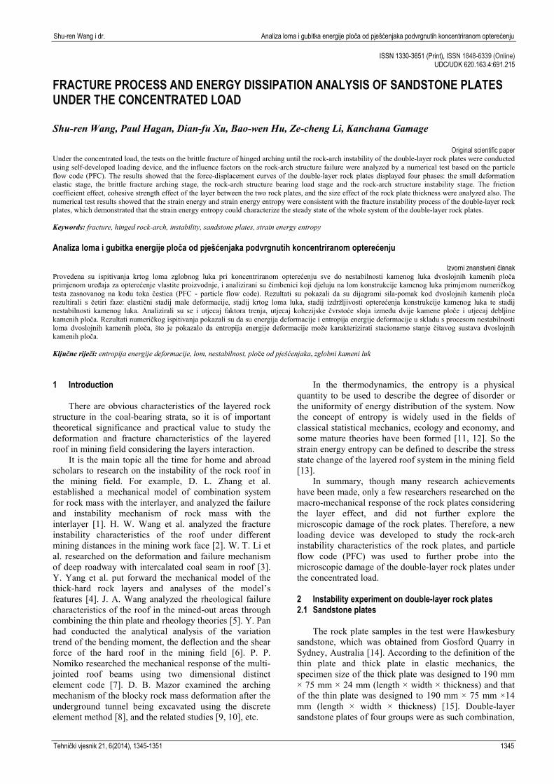
The MTS-851 rock mechanics testing machine was selected as loading equipment, and the load was controlled by vertical displacement and loading rate was set to 1×10⁻² mm/s, and all the samples were tested according to ISRM standards. The vertical force and displacement occurring in the process of testing were automatically recorded in real time by data acquisition system.
a) Loading test system
b) Double-layer plates rupture failure
c) Concentrated load component
d) Lateral load cell
Figure 1 Loading experiment for double-layer sandstone plates
The double-layer sandstone plates and the test device are shown in Fig. 1. The capacity of the lateral load cell LPX is 1000 kg. 2.3 Test results and analysis
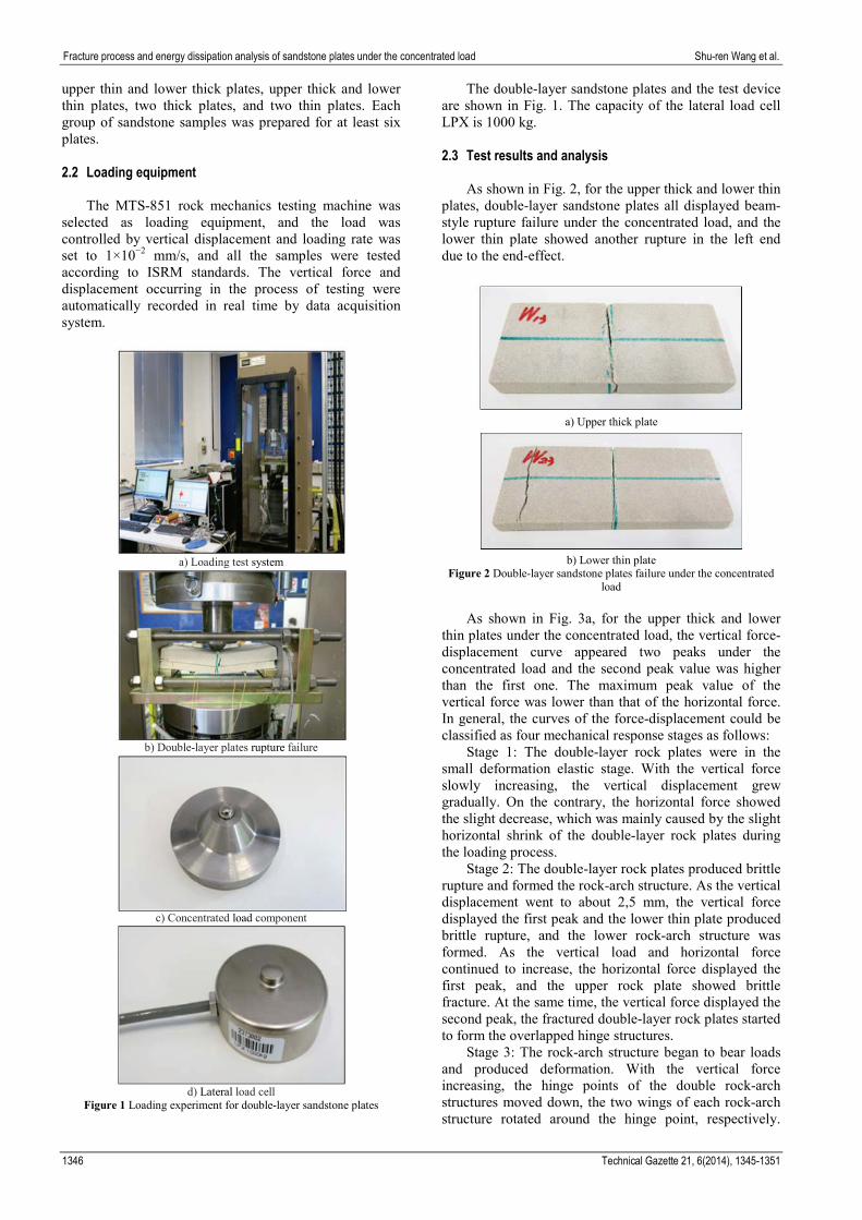
As shown in Fig. 2, for the upper thick and lower thin
plates, double-layer sandstone plates all displayed beam-style rupture failure under the concentrated load, and the lower thin plate showed another rupture in the left end due to the end-effect.
a) Upper thick plate
b) Lower thin plate
Figure 2 Double-layer sandstone plates failure under the concentrated load
As shown in Fig. 3a, for the upper thick and lower
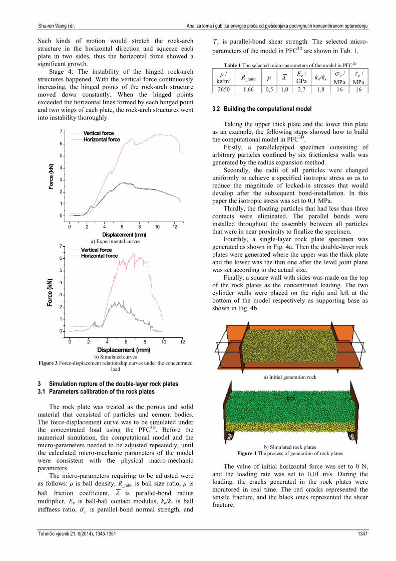
thin plates under the concentrated load, the vertical force-displacement curve appeared two peaks under the concentrated load and the second peak value was higher than the first one. The maximum peak value of the vertical force was lower than that of the horizontal force. In general, the curves of the force-displacement could be classified as four mechanical response stages as follows:
Stage 1: The double-layer rock plates were in the small deformation elastic stage. With the vertical force slowly increasing, the vertical displacement grew gradually. On the contrary, the horizontal force showed the slight decrease, which was mainly caused by the slight horizontal shrink of the double-layer rock plates during the loading process.
Stage 2: The double-layer rock plates produced brittle rupture and formed the rock-arch structure. As the vertical displacement went to about 2,5 mm, the vertical force displayed the first peak and the lower thin plate produced brittle rupture, and the lower rock-arch structure was formed. As the vertical load and horizontal force continued to increase, the horizontal force displayed the first peak, and the upper rock plate showed brittle fracture. At the same time, the vertical force displayed the second peak, the fractured double-layer rock plates started to form the overlapped hinge structures.
Stage 3: The rock-arch structure began to bear loads and produced deformation. With the vertical force increasing, the hinge points of the double rock-arch structures moved down, the two wings of each rock-arch structure rotated around the hinge point, respectively.
1346 Technical Gazette 21, 6(2014), 1345-1351
Shu-ren Wang i dr. Analiza loma i gubitka energije ploča od pješćenjaka podvrgnutih koncentriranom opterećenju
Such kinds of motion would stretch the rock-arch structure in the horizontal direction and squeeze each plate in two sides, thus the horizontal force showed a significant growth.
Stage 4: The instability of the hinged rock-arch structures happened. With the vertical force continuously increasing, the hinged points of the rock-arch structure moved down constantly. When the hinged points exceeded the horizontal lines formed by each hinged point and two wings of each plate, the rock-arch structures went into instability thoroughly.
0 2 4 6 8 10 12
0
1
2
3
4
5
6
7
Forc
e (k
N)
Displacement (mm)
Vertical force Horizontal force
a) Experimental curves
0 2 4 6 8 10 12
0
1
2
3
4
5
6
7
Forc
e (k
N)
Displacement (mm)
Vertical force Horizontal force
b) Simulated curves
Figure 3 Force-displacement relationship curves under the concentrated load
3 Simulation rupture of the double-layer rock plates 3.1 Parameters calibration of the rock plates
The rock plate was treated as the porous and solid
material that consisted of particles and cement bodies. The force-displacement curve was to be simulated under the concentrated load using the PFC3D. Before the numerical simulation, the computational model and the micro-parameters needed to be adjusted repeatedly, until the calculated micro-mechanic parameters of the model were consistent with the physical macro-mechanic parameters.
The micro-parameters requiring to be adjusted were as follows: ρ is ball density, R_ratio is ball size ratio, μ is ball friction coefficient, λ is parallel-bond radius multiplier, Ec is ball-ball contact modulus, kn/ks is ball stiffness ratio, cσ is parallel-bond normal strength, and
cτ is parallel-bond shear strength. The selected micro-parameters of the model in PFC3D are shown in Tab. 1.
Table 1 The selected micro-parameters of the model in PFC3D
ρ / kg/m3 R_ratio μ λ
Ec / GPa kn/ks cσ /
MPa cτ /
MPa 2650 1,66 0,5 1,0 2,7 1,8 16 16
3.2 Building the computational model
Taking the upper thick plate and the lower thin plate as an example, the following steps showed how to build the computational model in PFC3D.
Firstly, a parallelepiped specimen consisting of arbitrary particles confined by six frictionless walls was generated by the radius expansion method.
Secondly, the radii of all particles were changed uniformly to achieve a specified isotropic stress so as to reduce the magnitude of locked-in stresses that would develop after the subsequent bond-installation. In this paper the isotropic stress was set to 0,1 MPa.
Thirdly, the floating particles that had less than three contacts were eliminated. The parallel bonds were installed throughout the assembly between all particles that were in near proximity to finalize the specimen.
Fourthly, a single-layer rock plate specimen was generated as shown in Fig. 4a. Then the double-layer rock plates were generated where the upper was the thick plate and the lower was the thin one after the level joint plane was set according to the actual size.
Finally, a square wall with sides was made on the top of the rock plates as the concentrated loading. The two cylinder walls were placed on the right and left at the bottom of the model respectively as supporting base as shown in Fig. 4b.
a) Initial generation rock
b) Simulated rock plates
Figure 4 The process of generation of rock plates
The value of initial horizontal force was set to 0 N, and the loading rate was set to 0,01 m/s. During the loading, the cracks generated in the rock plates were monitored in real time. The red cracks represented the tensile fracture, and the black ones represented the shear fracture.
Tehnički vjesnik 21, 6(2014), 1345-1351 1347
Fracture process and energy dissipation analysis of sandstone plates under the concentrated load Shu-ren Wang et al.
3.3 Analysis of numerical simulation results
As shown in Fig. 3b, under the concentrated load, the simulated variation trend of the vertical force-horizontal force-displacement curves was basically the same as the physical experimental results, which confirmed the numerical credibility.
a) Brittle rupture stage
b) Hinged arch stage
c) Bearing loading stage
d) Rock-arch instability stage
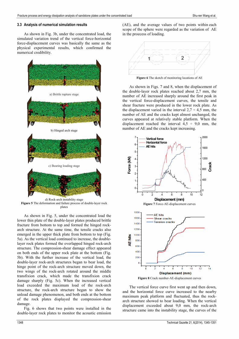
Figure 5 The deformation and failure process of double-layer rock plates
As shown in Fig. 5, under the concentrated load the
lower thin plate of the double-layer plates produced brittle fracture from bottom to top and formed the hinged rock-arch structure. At the same time, the tensile cracks also emerged in the upper thick plate from bottom to top (Fig. 5a). As the vertical load continued to increase, the double-layer rock plates formed the overlapped hinged rock-arch structure. The compression-shear damage effect appeared on both ends of the upper rock plate at the bottom (Fig. 5b). With the further increase of the vertical load, the double-layer rock-arch structures began to bear load, the hinge point of the rock-arch structure moved down, the two wings of the rock-arch rotated around the middle transfixion crack, which made the transfixion crack damage sharply (Fig. 5c). When the increased vertical load exceeded the maximum load of the rock-arch structure, the rock-arch structure began to show the unload damage phenomenon, and both ends at the bottom of the rock plates displayed the compression-shear damage.
Fig. 6 shows that two points were installed in the double-layer rock plates to monitor the acoustic emission
(AE), and the average values of two points within each scope of the sphere were regarded as the variation of AE in the proecess of loading.
21
Figure 6 The sketch of monitoring locations of AE
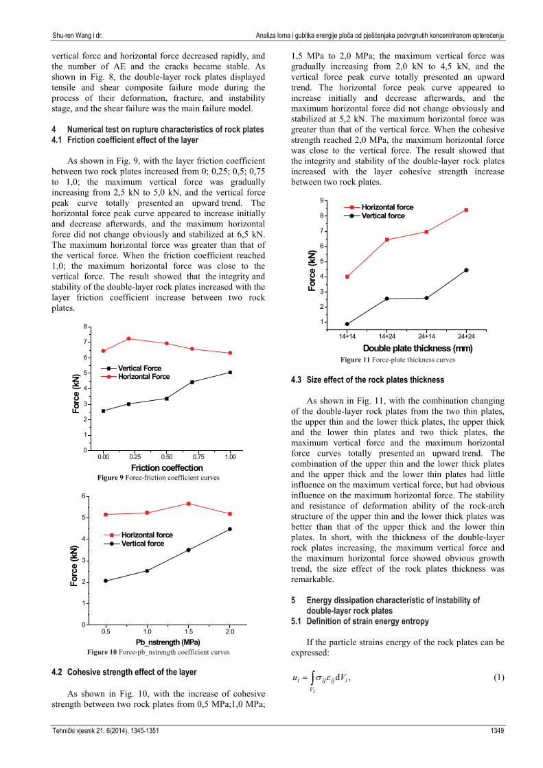
As shown in Figs. 7 and 8, when the displacement of
the double-layer rock plates reached about 2,7 mm, the number of AE increased sharply around the first peak in the vertical force-displacement curves, the tensile and shear fracture were produced in the lower rock plate. As the displacement varied in the interval 2,7 ÷ 4,5 mm, the number of AE and the cracks kept almost unchanged, the curves appeared at relatively stable platform. When the displacement reached the interval 4,5 ÷ 9,0 mm, the number of AE and the cracks kept increasing.
0 2 4 6 8 10 12
0
1
2
3
4
5
6
7
Forc
e (k
N)
Displacement (mm)
Vertical force Horizontal force
0
400
800
1200
1600
2000
AE hits
Crac
k
Figure 7 Force-AE-displacement curves
Figure 8 Crack number-AE-displacement curves
The vertical force curve first went up and then down,
and the horizontal force curve increased to the nearby maximum peak platform and fluctuated, thus the rock-arch structure showed to bear loading. When the vertical displacement exceeded about 9,0 mm, the rock-arch structure came into the instability stage, the curves of the
1348 Technical Gazette 21, 6(2014), 1345-1351
Shu-ren Wang i dr. Analiza loma i gubitka energije ploča od pješćenjaka podvrgnutih koncentriranom opterećenju
vertical force and horizontal force decreased rapidly, and the number of AE and the cracks became stable. As shown in Fig. 8, the double-layer rock plates displayed tensile and shear composite failure mode during the process of their deformation, fracture, and instability stage, and the shear failure was the main failure model. 4 Numerical test on rupture characteristics of rock plates 4.1 Friction coefficient effect of the layer
As shown in Fig. 9, with the layer friction coefficient between two rock plates increased from 0; 0,25; 0,5; 0,75 to 1,0; the maximum vertical force was gradually increasing from 2,5 kN to 5,0 kN, and the vertical force peak curve totally presented an upward trend. The horizontal force peak curve appeared to increase initially and decrease afterwards, and the maximum horizontal force did not change obviously and stabilized at 6,5 kN. The maximum horizontal force was greater than that of the vertical force. When the friction coefficient reached 1,0; the maximum horizontal force was close to the vertical force. The result showed that the integrity and stability of the double-layer rock plates increased with the layer friction coefficient increase between two rock plates.
0.00 0.25 0.50 0.75 1.000
1
2
3
4
5
6
7
8
Forc
e (k
N)
Friction coeffection
Vertical Force Horizontal Force
Figure 9 Force-friction coefficient curves
0.5 1.0 1.5 2.00
1
2
3
4
5
6
Forc
e (k
N)
Pb_nstrength (MPa)
Horizontal force Vertical force
Figure 10 Force-pb_nstrength coefficient curves
4.2 Cohesive strength effect of the layer
As shown in Fig. 10, with the increase of cohesive strength between two rock plates from 0,5 MPa;1,0 MPa;
1,5 MPa to 2,0 MPa; the maximum vertical force was gradually increasing from 2,0 kN to 4,5 kN, and the vertical force peak curve totally presented an upward trend. The horizontal force peak curve appeared to increase initially and decrease afterwards, and the maximum horizontal force did not change obviously and stabilized at 5,2 kN. The maximum horizontal force was greater than that of the vertical force. When the cohesive strength reached 2,0 MPa, the maximum horizontal force was close to the vertical force. The result showed that the integrity and stability of the double-layer rock plates increased with the layer cohesive strength increase between two rock plates.
14+14 14+24 24+14 24+24
1
2
3
4
5
6
7
8
9
Forc
e (k
N)
Double plate thickness (mm)
Horizontal force Vertical force
Figure 11 Force-plate thickness curves
4.3 Size effect of the rock plates thickness
As shown in Fig. 11, with the combination changing of the double-layer rock plates from the two thin plates, the upper thin and the lower thick plates, the upper thick and the lower thin plates and two thick plates, the maximum vertical force and the maximum horizontal force curves totally presented an upward trend. The combination of the upper thin and the lower thick plates and the upper thick and the lower thin plates had little influence on the maximum vertical force, but had obvious influence on the maximum horizontal force. The stability and resistance of deformation ability of the rock-arch structure of the upper thin and the lower thick plates was better than that of the upper thick and the lower thin plates. In short, with the thickness of the double-layer rock plates increasing, the maximum vertical force and the maximum horizontal force showed obvious growth trend, the size effect of the rock plates thickness was remarkable.
5 Energy dissipation characteristic of instability of
double-layer rock plates 5.1 Definition of strain energy entropy
If the particle strains energy of the rock plates can be expressed:
,d∫=iV
iijiji Vu εσ (1)
Tehnički vjesnik 21, 6(2014), 1345-1351 1349
Fracture process and energy dissipation analysis of sandstone plates under the concentrated load Shu-ren Wang et al.
where Vi was the volume of the unit i, εij was the element strain of the unit i, σij was the element stress of the unit i.
If the units strain energy of the double-layer rock plates were added together, then the total strain energy of the double-layer rock plates system was
1
n
ii
U u=
=∑ , (2)
supposed that Pi = ui/U, (i = 1, 2, …, n), and pi met the requirement as follows:
11
n
ii
P=
=∑ , (3)
where Pi ≥ 0 (i = 1 , 2 , …, n) is the percentage of the strain energy ui of the ith element in the total strain energy U, which showed the strain energy distribution of the double-layer rock plates system. So the strain energy entropy could be defined as follows:
.ln )(1∑=
−=n
iii PPxS (4)
Eq. (4) could transform the strain energy of the
double-layer rock plates system into the entropy value, that is, the strain energy entropy could be used to describe the strain energy distribution of the double-layer rock plates system in order to reflect the change process of the system state.
5.2 Energy dissipation characteristics of the plates
system As shown in Fig. 12, five monitoring points were
installed in the double-layer rock plates, and each monitoring site could detect the strain energy change within the scope of the sphere.
Figure 12 Monitoring locations of strain energies
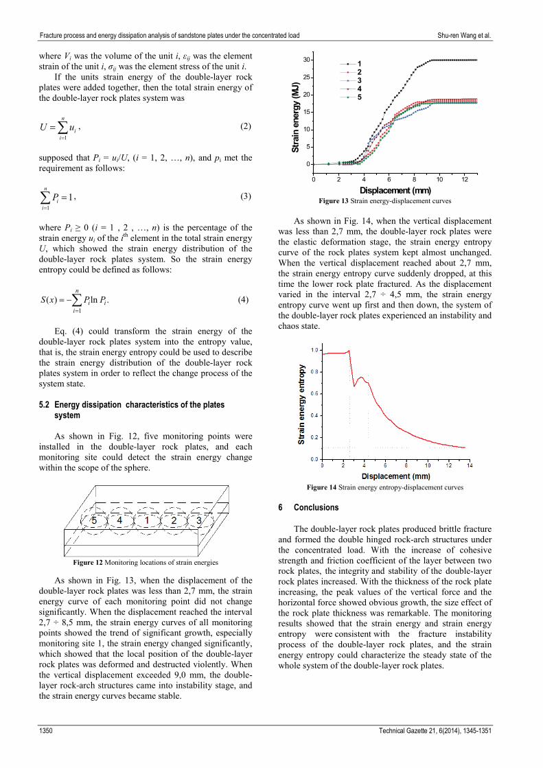
As shown in Fig. 13, when the displacement of the
double-layer rock plates was less than 2,7 mm, the strain energy curve of each monitoring point did not change significantly. When the displacement reached the interval 2,7 ÷ 8,5 mm, the strain energy curves of all monitoring points showed the trend of significant growth, especially monitoring site 1, the strain energy changed significantly, which showed that the local position of the double-layer rock plates was deformed and destructed violently. When the vertical displacement exceeded 9,0 mm, the double-layer rock-arch structures came into instability stage, and the strain energy curves became stable.
0 2 4 6 8 10 12
0
5
10
15
20
25
30
Stra
in e
nerg
y (M
J)
Displacement (mm)
1 2 3 4 5
Figure 13 Strain energy-displacement curves
As shown in Fig. 14, when the vertical displacement
was less than 2,7 mm, the double-layer rock plates were the elastic deformation stage, the strain energy entropy curve of the rock plates system kept almost unchanged. When the vertical displacement reached about 2,7 mm, the strain energy entropy curve suddenly dropped, at this time the lower rock plate fractured. As the displacement varied in the interval 2,7 ÷ 4,5 mm, the strain energy entropy curve went up first and then down, the system of the double-layer rock plates experienced an instability and chaos state.
Figure 14 Strain energy entropy-displacement curves
6 Conclusions
The double-layer rock plates produced brittle fracture and formed the double hinged rock-arch structures under the concentrated load. With the increase of cohesive strength and friction coefficient of the layer between two rock plates, the integrity and stability of the double-layer rock plates increased. With the thickness of the rock plate increasing, the peak values of the vertical force and the horizontal force showed obvious growth, the size effect of the rock plate thickness was remarkable. The monitoring results showed that the strain energy and strain energy entropy were consistent with the fracture instability process of the double-layer rock plates, and the strain energy entropy could characterize the steady state of the whole system of the double-layer rock plates.
1350 Technical Gazette 21, 6(2014), 1345-1351
Shu-ren Wang i dr. Analiza loma i gubitka energije ploča od pješćenjaka podvrgnutih koncentriranom opterećenju
Acknowledgments This work was financially supported by the National
Natural Science Foundation of China (51474188; 51074140; 51310105020), the Natural Science Foundation of Hebei Province of China (E2014203012) and Program for Taihang Scholars, all these are gratefully acknowledged.
7 References [1] Zhang, D. L.; Wang, Y. H.; Qu, T. Z. Influence analysis of
interband on stability of stratified rock mass. // Chinese Journal of Rock Mechanics and Engineering. 19, 2(2000), pp. 140-144.
[2] Wang, H. W.; Chen, Z. H.; Du, Z. C.; Li, J. W. Application of elastic thin plate theory to change rule of roof in underground stope. // Chinese Journal of Rock Mechanics and Engineering. 25, S2(2006), pp. 3769-3774.
[3] Li, W. T.; Wang, Q.; Li, S. C.; Wang, D. C.; Huang, F. C.; Zuo, J. Z.; Zhang, S. G.; Wang, H. T. Deformation and failure mechanism analysis and control of deep roadway with intercalated coal seam in roof. // Journal of China Coal Society. 39, 1(2014), pp. 47-56.
[4] Yang, Y.; Feng, G. C.; Liang, B. Study on the Mechanical Deformation of Overlying Thick-Hard Rock Layers after Mining. // Science, Technology and Engineering. 9, 6(2009), pp. 1402-1405.
[5] Wang, J. A.; Shang, X. C.; Ma, H. T. Investigation of catastrophic ground collapse in Xingtai gypsum mines in China. // International Journal of Rock Mechanics and Mining Sciences. 45, 8(2008), pp. 1480-1499.
[6] Pan, Y.; Gu, S. T.; Qi, Y. S. Analytic solution of tight roof’s bending moment, deflection and shear force under advanced super charger load and supporting resistance before first weighting. // Chinese Journal of Rock Mechanics and Engineering. 32, 8(2013), pp. 1545-1553.
[7] Nomikos, P. P.; Sofianos, A. I.; Tsoutrelis, C. E. Structural response of vertically multi-jointed roof rock beams. // International Journal of Rock Mechanics and Mining Sciences. 39, 1(2002), pp. 79-94.
[8] Bakun-Mazor, D.; Hatzor, Y. H.; Dershowitz, W. S. Modeling mechanical layering effects on stability of underground openings in jointed sedimentary rocks. // International Journal of Rock Mechanics and Mining Sciences. 46, 2(2009), pp. 262-71.
[9] Mi, G. F.; Li, C. Y.; Gao, Z. Application of numerical simulation on cast-steel toothed plate. // Engineering Review. 34, 1(2014), pp. 1-6.
[10] Milošević, B.; Mijalković, M.; Petrović, Ž.; Hadžimujović, M.; Mladenović, B. Comparative analysis of limit bearing capacity of frames depending on the character of the load. // Technical Gazette. 20, 6(2013), pp. 1001-1009.
[11] Teng, S. H.; Lu, M.; Zhang, J.; Tan, Z. G.; Zhuang, Z. W. Entropy theory and information granularity in information systems. // Computer Engineering & Science. 34, 4(2012), pp. 94-101.
[12] Li, Z. W.; Yang, D. W.; Lei, H. M. Evapotranspiration model based on the maximum entropy production principle. // Journal of Tsinghua University (Science and Technology). 52, 6(2012), pp. 785-790.
[13] Yin, J. F.; Wang, S. R., Wang, Z. Q.; Yu, J. M.; Cao, C. Disturbance effects analysis of the coal pillar-roof system caused by a sudden instability coal pillar. // Disaster Advances. 6, 13(2013), pp. 29-37.
[14] Wang, S. R.; Hagan, P.; Cheng Y. Experimental research on the instability characteristics of double-layer rock plates
based on MTS-AE system. // Applied Mathematics & Information Sciences. 7, 1L(2013), pp. 339-345.
[15] Xu, Z. L. A concise course in elasticity. 3rd ed. Beijing: Higher Education Press, 2002.
Authors’ addresses Shu-ren Wang, Ph.D., Professor (Corresponding author) 1) Opening Laboratory for Deep Mine Construction, Henan Polytechnic University, 2001 Century Avenue, Jiaozuo, Henan Province, 454003, China 2) School of Civil Engineering and Mechanics, Yanshan University, No. 438 Hebei West Street, Haigang District, Qinhuangdao, 066004, China E-mail: [email protected] Paul Hagan, Ph.D., Associate Professor School of Mining Engineering, University of New South Wales, Sydney, East Wing, Old Main Building, Gate 14 Barker Street, Kingsford, NSW, 2052, Australia E-mail: [email protected] Dian-fu Xu, postgraduate School of Civil Engineering and Mechanics, Yanshan University, No. 438 Hebei West Street, Haigang District, Qinhuangdao, 066004, China E-mail: [email protected] Bao-wen Hu, postgraduate School of Civil and Environmental Engineering, University of Science and Technology Beijing, No. 30 Xueyuan Road, Haidian District, Beijing 100083, China E-mail: [email protected] Ze-cheng Li, postgraduate School of Mining Engineering, University of New South Wales, Sydney, East Wing, Old Main Building, Gate 14 Barker Street, Kingsford, NSW, 2052, Australia E-mail: [email protected] Kanchana Gamage, Technical officer School of Mining Engineering, University of New South Wales, Sydney, East Wing, Old Main Building, Gate 14 Barker Street, Kingsford, NSW, 2052, Australia E-mail: [email protected]
Tehnički vjesnik 21, 6(2014), 1345-1351 1351