Embed Size (px)
Citation preview
Non-Destructive Testing: Its Relation to Fracture Mechanics and Component DesignAuthor(s): J. M. Coffey and M. J. WhittleSource: Philosophical Transactions of the Royal Society of London. Series A, Mathematical andPhysical Sciences, Vol. 299, No. 1446, Fracture Mechanics in Design and Service: 'Living WithDefects' (Jan. 23, 1981), pp. 93-110Published by: The Royal SocietyStable URL: http://www.jstor.org/stable/36734 .
Accessed: 02/05/2014 19:37
Your use of the JSTOR archive indicates your acceptance of the Terms & Conditions of Use, available at .http://www.jstor.org/page/info/about/policies/terms.jsp
.JSTOR is a not-for-profit service that helps scholars, researchers, and students discover, use, and build upon a wide range ofcontent in a trusted digital archive. We use information technology and tools to increase productivity and facilitate new formsof scholarship. For more information about JSTOR, please contact [email protected].
.
The Royal Society is collaborating with JSTOR to digitize, preserve and extend access to PhilosophicalTransactions of the Royal Society of London. Series A, Mathematical and Physical Sciences.
http://www.jstor.org
This content downloaded from 130.132.123.28 on Fri, 2 May 2014 19:37:59 PMAll use subject to JSTOR Terms and Conditions
Phil. Trans. R. Soc. Lond. A 299, 93-110 (1981) [ 93 ] Printed in Great Briatin
Non-destructive testing: its relation to fracture mechanics and component design
BY J. M. COFFEY AND M. J. WHITTLE N.D. T. Applications Centre, Central Electricity Generating Board, N. W. Region,
Scientific Services Department, Timpson Road, Manchester M23 9LL, U.K.
Five non-destructive testing (n.d.t.) methods are widely used for defect detection: these are magnetic particle, dye penetrant, electrical eddy currents, radiography and ultrasonics. The first three can detect only surface-breaking or immediately sub- surface defects, while radiography and ultrasonics can also find embedded, remote defects. Ultrasonics is far more sensitive to cracks than is radiography; moreover, of all the n.d.t. methods, only ultrasonics can in general measure a crack's through-wall position and size. Consequently only ultrasonics is fully compatible with fracture mechanics requirements. Used in conjunction with fracture mechanics, ultrasonics has proved a powerful technique for demonstrating component integrity.
After a brief description of the five main n.d.t. methods, the paper concentrates on ultrasonics. Basic ultrasonic techniques for detecting, positioning and sizing cracks are described and the main sources of error indicated. Two approaches to defect size assessment are recognized. The approach of endeavouring to measure crack size as accurately as possible is most appropriate to manual testing by skilled practitioners. The alternative involves measuring convenient parameters of the ultrasonic echo rather than of the defect itself, and aims to promote a speedy, reproducible examina- tion.
The subsequent discussion is of the implications that the limitations of n.d.t. techniques have for component design and fracture mechanics assessment. Among the points raised are the importance of access and component geometry, the need for cooperation in planning inspections and the ability of ultrasonics to distinguish significant from insignificant defects. The paper closes with two examples of the beneficial joint application of ultrasonics and fracture mechanics.
1. INTRODUCTION
In a Discussion Meeting on the application of fracture mechanics, it is appropriate to consider non-destructive testing (n.d.t.). This is because n.d.t. techniques are the means by which defects are detected in the first place, and then measured to provide the positional and size information essential to any fracture mechanics assessment of defect significance. Indeed, our ability to exploit fracture mechanics is due largely to the reliability of n.d.t. methods. As we shall see, of all the n.d.t. techniques, ultrasonics has a special ability to provide the information required by fracture mechanics, while fracture mechanics has in turn set targets for the performance of ultrasonics. This interaction between the two disciplines explains their parallel growth in recent years.
In this short review of non-destructive testing we first present, in ?2, the principles and essential features of the five most widely used techniques for detecting flaws and explain why ultrasonics has become pre-eminent. The remainder of the review concentrates on ultrasonics. Section 3 discusses the detection, location and measurement of defects by this technique. Section 4 continues the theme with examples of the practical application of ultrasonics in
This content downloaded from 130.132.123.28 on Fri, 2 May 2014 19:37:59 PMAll use subject to JSTOR Terms and Conditions
94 J. M. COFFEY AND M. J. WHITTLE
conjunction with fracture mechanics, and a discussion of the implications for component design. Finally the general conclusions are drawn in ? 5.
2. THE MAIN N.D.T. TECHNIQUES
Non-destructive testing techniques can be classified according to whether (i) they are sensitive only to defects in or very close to an accessible surface, or (ii) they can also detect defects remotely within the volume of the material and at inaccessible surfaces. Of the principal methods, magnetic testing, dye penetrants and electrical eddy currents are in the first category, whereas ultrasonics and radiography are the only two in the second. A comprehensive textbook on the five methods was edited by McMaster (I963).
Fracture mechanics has shown that sharp, crack-like defects are more dangerous than rounded, globular ones. Consequently, one criterion for judging the usefulness of an n.d.t. technique is its ability to detect cracking. Fracture mechanics has also emphasized the impor- tance of defects at or near surfaces. Moreover, engineering experience of failures is that most in-service cracks initiate at surfaces by corrosion or fatigue. These considerations underline the importance of inspecting the component's surface. For accessible surfaces, one of the three methods sensitive only to surface-breaking defects is usually chosen. We now outline these techniques in turn.
2.1. Magnetic methods
Magnetic techniques (see, for example, Betz I966; Bezer I97I) are applicable only to ferro- magnetic materials. A magnetic flux is induced in the surface of the component, the flux in the metal greatly exceeding that in the surrounding air. Any surface or near-surface defect that happens to cut the flux lines will cause flux to leak from the metal and so create an anomalously high field in the air above. This leakage field may be detected by using a field strength meter or, more commonly, by the local collection of fine magnetic particles applied as dust or in liquid suspension. Subsurface defects give weak, diffuse indications, so magnetic methods are usually intended to detect only surface defects.
The magnetic flux may be induced, for instance, by passing a current through the component or by using permanent or electro-magnets. The choice is made by considering the practical convenience and the need to induce a flux approximately at right angles to the defects being sought. The reliability of crack detection depends on many test parameters including the induced flux density and orientation, the magnetic properties of the material, the separation of the crack faces, the use of either a.c. or d.c. fields, the component geometry and surface condition, and the viewing conditions. Fortunately, the factors governing the choice of these parameters are sufficiently well understood for high sensitivity to surface cracks to be achieved routinely (see, for example, BS M35 I970). In fact, magnetic particle inspection, especially with fluorescent magnetic inks, is acknowledged as the most sensitive of all n.d.t. methods to surface defects, the ultimate sensitivity being set only by the quality of surface preparation of the component. These reasons, together with speed and economy, make magnetic particle inspection the first choice for surface crack detection in ferritic steel.
2.2. Dye penetrant testing On non-ferritic components where magnetic methods are ineffiective, the most popular
testing technique involves the use of penetrating dye (see, for example, Betz I969; Hislop I970).
This content downloaded from 130.132.123.28 on Fri, 2 May 2014 19:37:59 PMAll use subject to JSTOR Terms and Conditions
N.D.T. AND FRACTURE MECHANICS 95
The principle is very simple. The component is cleaned and sprayed with a coloured or fluorescent dye, which seeps into any open surface-breaking defects. After allowing sufficient time for penetration, excess dye is wiped away and the surface dusted with chalk. The chalk acts like blotting paper and defects are revealed as lines of dye against the white chalky back- ground. The method is widely used and acknowledged to have high sensitivity to cracks. Penetrants, however, are not as reliable as magnetic methods because cracks can be blocked by foreign matter such as paint or corrosion products, or may be burred over by machining, thereby restricting the ingress of dye. In general, therefore, the reliability of penetrant methods is strongly influenced by the surface preparation of the component and so is difficult to quantify. Magnetic methods do not suffer this limitation because magnetic flux will leak through any blockage and still attract magnetic particles.
2.3. Electrical eddy currents When a coil carrying an alternating current is placed near a metal surface, eddy currents
are induced in the metal surface. The penetration depth of the eddy currents, characterized by the 'skin depth', is determined by the frequency of the current and the magnetic per- rneability and electrical conductivity of the metal. In a ferritic component the skin depth is considerably less than 1 mm at all practical frequencies, whereas in a non-magnetic conductor it may be several millimetres. If, as the coil is scanned over the metal surface, a defect within the skin depth is encountered, the flow of eddy currents is distorted and the associate(d magnetic field changes. This field links the search coil, so the coil senses the defect as a local change in its impedance.
The problems in eddy current testing arise from the difficulty of relating the change in impedance to the size of the defect, and from the confusing influence on impedance of many extraneous features such as the distance between the coil and the component and local varia- tions in material properties. The sensitivity of the technique to cracks depends ultimately on the surface conditions and homogeneity of the material under test, but under favourable conditions the coil configuration can be arranged to detect defects considerably smaller than 1 mm. Absolute measurement of defect depth is not at present possible, so estimations of severity are made by comparing the defect's response to that observed from a standard flaw such as a fine slot. Considerable potential for further improvement exists, however, and eddy current systems that use two or more frequencies simultaneously are showing great promise for the more accurate description of both defect size and type (Libby I973; Dodd I977).
These sketches of magnetic, penetrant and eddy current inspection methods show simple, effective techniques for detecting cracks in or near the accessible surfaces of engineering components. They have long been used for quality control during manufacture and for in- service crack detection. However their relation to quantitative fracture mechanics is remote. For instance, while the length of a crack along the surface can be measured, the much more important through-wall depth cannot. Consequently the information required for fracture mechanics assessment of defect significance cannot be provided. Fortunately, in many circum- stances this is not important since the usual policy with surface-breaking defects is simply to grind them out. If a subsequent repair cannot then be made, at least a crack has been replaced by a rounded depression with a consequent lowering of stress concentration.
We now turn our attention to radiography and ultrasonics, which are the two techniques
This content downloaded from 130.132.123.28 on Fri, 2 May 2014 19:37:59 PMAll use subject to JSTOR Terms and Conditions
96 J. M. COFFEY AND M. J. WHITTLE
capable of detecting defects lying in inaccessible surfaces of a component or within the body of the material.
2.4. Radiographly
Radiography is the traditional method for detecting subsurface defects. A source of X- or y-rays is placed on one side of the component and a suitably sensitive photographic film on the other. Defects are revealed by their lower attenuation to X-rays and the consequent increased blackening of the film by rays that have passed through the defect. Radiography is particularly well suited to finding defects that occupy a volume of material, such as gas pores and shrinkage in castings and slag inclusions in welds. Such defects arise during component fabrication and so radiography is widely used for castings and to assess the general quality of welding. Indeed, the 1977 edition of ?III of the A.S.M.E. nuclear pressure vessel code, which relates to the fabrication of nuclear power plant components, requires only radiography.
The main weakness of radiography is its poor sensitivity to cracks. Unless the radiation beam strikes the crack almost tangentially, there is negligible differential absorption between rays passing through the crack and those through adjacent sound material. To achieve tangential rays, the radiation source must be in the plane of the crack. Consequently, without prior knowledge of the crack orientation, detection of unknown cracks would involve an impractical number of exposures at different source positions. Indeed, jagged cracks may be impossible to detect whatever the source position. The detection of cracks by radiography has been studied by several authors including Halmshaw & Hunt (I975), Halmshaw (I979a) and Yokota & Ishii (I979). Their general conclusion is that crack detection is influenced strongly by the separation of the crack faces and that for a typical effective separation of 0.02 mm cracks will not be detected if the grazing angle of the rays on the crack exceeds 10'.
A second major weakness of radiography is that even if a crack is detected, neither its position within the component nor its extent in the through-thickness direction can be measured from the radiograph. Possible special methods for obtaining such information by radiography have recently been discussed by Halmshaw (I 979 b). He considers two methods, one which calibrates the image density by including in the radiograph a standard block containing steps of varying height, and another which involves taking two radiographs from slightly different angles. Both techniques have serious deficiencies and are not used in practice.
We can conclude, therefore, that while radiography is ideal for quality control during casting and welding, for all practical purposes it has poor sensitivity to cracks and cannot provide the through-wall position and size required for defect assessment by fracture mechanics. It is interesting to note that traditional codes of acceptance for engineering components, such as BS 5500 (I976) for pressure vessels, were written with radiography in mind as the method of inspection. None of these codes will allow cracks or other planar defects, regardless of their size. The reason is largely that any crack big enough to show on a radiograph would almost certainly prove significant. Other points to note about radiography are that it is inconvenient because of the necessary safety precautions, and difficult to apply in service in remote, hot or radio- active environments.
2.5. Ultrasonics
Fortunately, ultrasonics, the alternative volumetric inspection technique, is free from the shortcomings of radiography. Ultrasonics is both sensitive to cracks and capable of measuring the dimensions relevant to fracture mechanics. It is also safe and capable of being applied remotely in difficult environmental conditions.
This content downloaded from 130.132.123.28 on Fri, 2 May 2014 19:37:59 PMAll use subject to JSTOR Terms and Conditions
N.D.T. AND FRACTURE MECHANICS 97
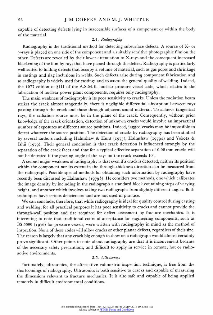
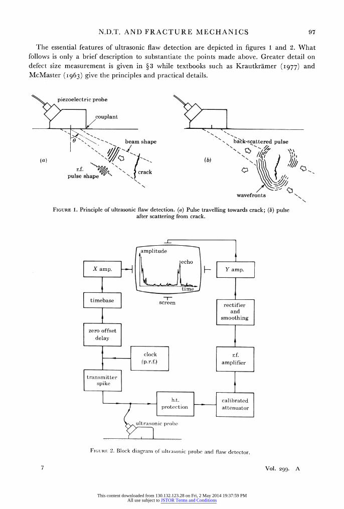
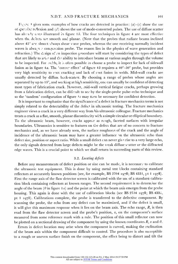
The essential features of ultrasonic flaw detection are depicted in figures 1 and 2. What follows is only a brief description to substantiate the points made above. Greater detail on defect size measurement is given in ?3 while textbooks such as Krautkramer (I977) and McMaster (I963) give the principles and practical details.
pizoletic probe
y ~ ~~~ ouplanty I 1
N -
beam shape back-scattered pulse
(a) (b) k;
afte scrattein fro crck
pulse sqahlape N N,
wavefrontsN
FIGURE 1. Principle of ultrasonic flaw detection. (a) Pulse travelling towards crack; (b) pulse after scattering from crack.
ampi tude
echo X amp. Y Y amp.
timebase ~ ~ ~ ~ im timebase ~~screen rectifier
and
t c_l ..occli rfte
l ~~protec tion attenuator
ultrrasonic prohe
Fic;uiil 2. Block diagram of ulltrasonic probe and flaw detector.
7 Vol. 299. A
This content downloaded from 130.132.123.28 on Fri, 2 May 2014 19:37:59 PMAll use subject to JSTOR Terms and Conditions
98 J. M. COFFEY AND M.J. WHITTLE
Figure 1 a shows a piezoelectric probe radiating a beam of pulsed elastic waves into the component. The probe is acoustically coupled to the test piece by a fluid such as grease, and is scanned over the surface so that the ultrasonic beam searches the volume. Figure I b shows how metallurgical defects (and geometrical features of the component) reflect the incident pulse, returning a greater or lesser amount of energy to the probe, which now acts as receiver. After a delay corresponding to the time of flight of the pulse, a defect echo is detected.
The probe is electrically connected to a 'flaw detector', whose basic circuit elements are shown in figure 2. The transmitter channel repetitively excites the piezoelectric probe, while in reception the weak radio frequency echoes are amplified, rectified, smoothed and displayed on the c.r.t. screen. This type of display is effectively a graph of echo amplitude as a function of time of flight and is known as 'A-scan'.
This mode of operation in which the same probe acts alternatively as transmitter and receiver is the most often used because of its simplicity and effectiveness. The axis of the screen is easily calibrated so that the slant range of a defect can be read directly from the position of its echo. The measurement of defect size is discussed in ?3; basically it involves measuring the distance the probe can be displaced along the component's surface and the defect still lie within the ultrasonic beam. In exceptional circumstances the strength of the echo can be a measure of defect size.
A further facility offered by ultrasonics is the ability to monitor crack growth. This is in- valuable in circumstances where a crack is found and measured, and fracture mechanics predicts an acceptably low growth rate during service. A decision to operate the plant without remedial action may rest upon the continuous or periodic monitoring of the crack by ultra- sonics to guard against unforeseen operating conditions. The techniques for continuously measuring small amounts of growth usually have to be different from those used for a periodic remeasurement of size. Some of these methods have been used in laboratories for monitoring crack growth in mechanical test specimens and have recently been reviewed (Coffey i980).
In ferritic steel, aluminium and many other important engineering materials, echoes can be detected from almost any defect if the amplifier gain is sufficiently high. This inherently high sensitivity has two origins. First, the ultrasonic reflexion coefficient of defect boundaries is usually very close to unity. Secondly, in the pulse-echo technique the background noise on the flaw detector screen is very low, arising mainly from random scatter at grain boundaries throughout the material. Consequently a defect signal just distinguishable from noise is very weak indeed. Paradoxically, one of the difficulties with ultrasonic testing arises from this inherently high sensitivity. As we shall see in the next section, the absence of a good correlation between defect size and echo amplitude usually compels the operator to work at high sensi- tivities to ensure the detection of all serious defects. He is then faced with the practical problem of distinguishing crack echoes from those due only to small, innocuous defects such as slag inclusions. While in principle ultrasonics has the potential to accomplish this distinction, practical difficulties and ambiguities often hamper the task of searching for cracks.
Among the disadvantages of the simple basic ultrasonic system outlined above are the sub- jective way in which the echoes must be interpreted by the operator, and the lack of a perma- nent, objective record of the test. Recent technological advances, however, have largely rectified this latter shortcoming.
The four important advantages of ultrasonics - sensitivity to cracks at all positions, ability to measure defect position and size, ability to monitor crack growth, and economy and safety
This content downloaded from 130.132.123.28 on Fri, 2 May 2014 19:37:59 PMAll use subject to JSTOR Terms and Conditions
N.D.T. AND FRACTURE MECHANICS 99
of application - have led to its adoption on an increasingly wide scale, and this trend seems certain to continue (Coffey et al. 1979; Coffey & Wlhittle I979). It is no accident that ultra- sonics and fracture mechanics have seen parallel growth over the past 15 years. The ability of ultrasonics to measure the through-wall position and size of defects largely satisfies the needs of fracture mechanics and has made the application of fracture mechanics possible to a wide range of problems.
2.6. Summary
In this section, we have discussed the great value of penetrant, magnetic particle and eddy current methods in detecting near-surface cracking. These techniques, however, are unable to determine crack depth and therefore cannot satisfy fracture mechanics requirements. For embedded and far-surface defects, radiography or ultrasonics must be used. Of these, only ultrasonics can reliably detect cracks and measure their important dimensions and growth rates. Ultrasonics, therefore, is the n.d.t. method most suited to fracture mechanics.
incident shear beam
wavefronts and \ ~N \ ,,="rays of
'<Vxd \edge wave
reflected \ shear beam
- ,,' "' 2 diffuse -,- scatter
reflected r , s compression L_
beam II(frt l </ / ledge wave
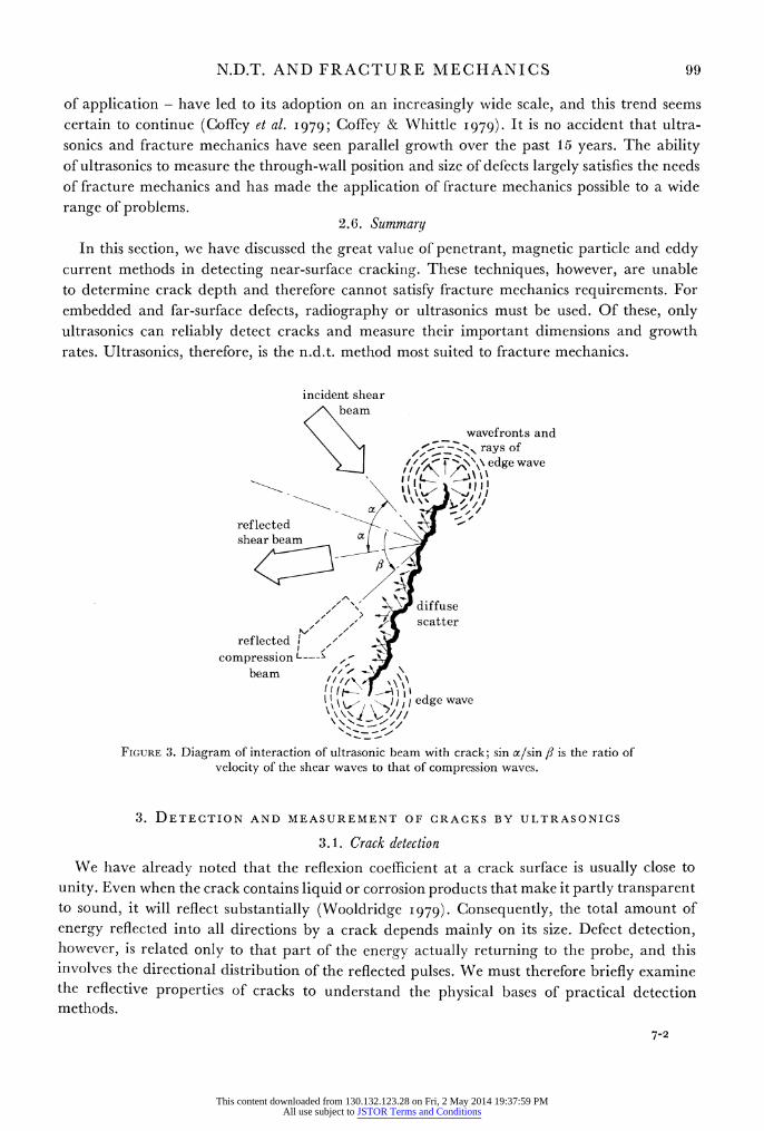
FIGURE 3. Diagram of interaction of ultrasonic beam with crack; sin x/sin ,B is the ratio of velocity of the shear waves to that of compression waves.
3. DETECTION AND MEASUREMENT OF CRACKS BY ULTRASONICS
3.1. Crack detection
We have already noted that the reflexion coefficient at a crack surface is usually close to unity. Even when the crack contains liquid or corrosion products that make it partly transparent to sound, it will reflect substantially (Wooldridge I979). Consequently, the total amount of energy reflected into all directions by a crack depends mainly on its size. Defect detection, however, is related only to that part of the energy actually returning to the probe, and this involves the directional distribution of the reflected pulses. We must therefore briefly examine the reflective properties of cracks to understand the physical bases of practical detection methods.
7-2
This content downloaded from 130.132.123.28 on Fri, 2 May 2014 19:37:59 PMAll use subject to JSTOR Terms and Conditions
100 J. M. COFFEY AND M.J. WHITTLE
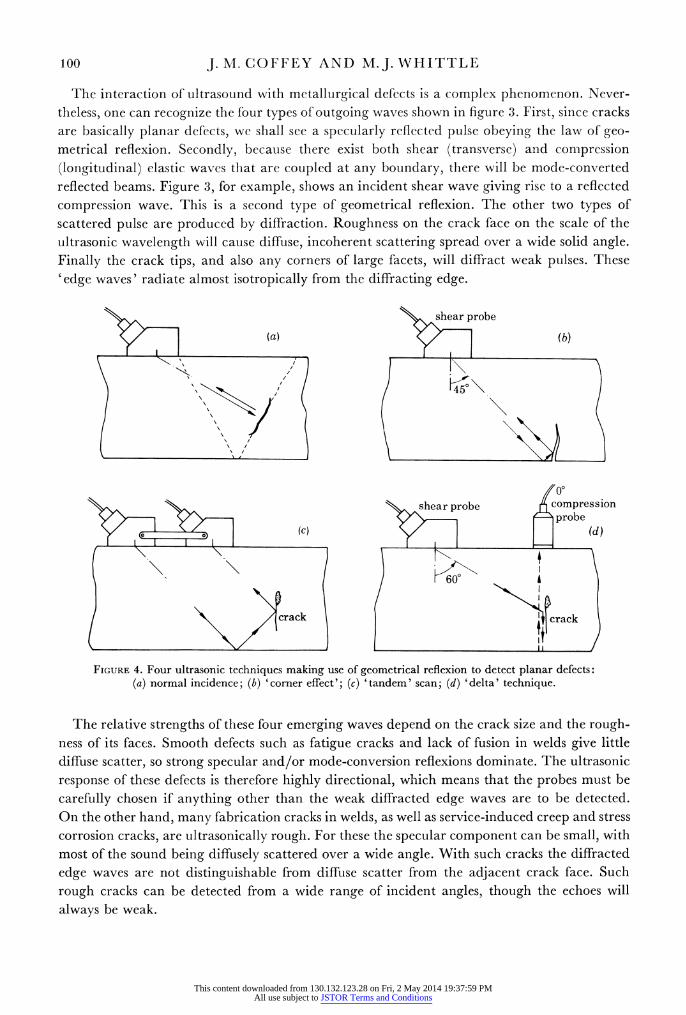
Trhe interaction of ultrasound with metallurgical defects is a complex phenomenon. Never- theless, one can recognize the four types of outgoing waves shown in figure 3. First, since cracks are basically planar defects, we shall see a specularly reflected pulse obeying the law of geo- metrical reflexion. Secondly, becauise there exist both shear (transverse) and compression (longitudinal) elastic waves that are coupled at any boundary, there will be mode-converted reflected beams. Figure 3, for example, shows an incident shear wave giving rise to a reflected compression wave. This is a second type of geometrical reflexion. The other two types of scattered pulse are produced by diffraction. Roughness on the crack face on the scale of the ultrasonic wavelength will cause diffuse, incoherent scattering spread over a wide solid angle. Finally the crack tips, and also any corners of large facets, will diffract weak pulses. These 'edge waves' radiate almost isotropically from the diffracting edge.
< % ~~~~~~~~~~~~~shear probe
~~~~~~(a) (b)
shear probe compression
crack j\crack
FIGURE 4. Four ultrasonic techniques making use of geometrical reflexion to detect planar defects: (a) normal incidence; (b) 'corner effect'; (c) 'tandem' scan; (d) 'delta' technique.
The relative strengths of these four emerging waves depend on the crack size and the rough- ness of its faces. Smooth defects such as fatigue cracks and lack of fusion in welds give little diffuse scatter, so strong specular and/or mode-conversion reflexions dominate. The ultrasonic response of these defects is therefore highly directional, which means that the probes must be carefully chosen if anything other than the weak diffracted edge waves are to be detected. On the other hand, many fabrication cracks in welds, as well as service-induced creep and stress corrosion cracks, are ultrasonically rough. For these the specular component can be small, with most of the sound being diffusely scattered over a wide angle. With such cracks the diffracted edge waves are not distinguishable from diffuse scatter from the adjacent crack face. Such rough cracks can be detected from a wide range of incident angles, though the echoes will always be weak.
This content downloaded from 130.132.123.28 on Fri, 2 May 2014 19:37:59 PMAll use subject to JSTOR Terms and Conditions
N.D.T. AND FRACTURE MECHANICS 101
t gives somt examples of how cracks are detected in practice: (a)-(c) show the use of spe2,1q: rtflexion and td) shows the use of mode-converted pulses. The use of diffuse scatter has ali Ga
' ueo illustrated >i figure lb. The four techniques in figure 4 are most effective
when tht dCecects a;'e smooth and planar. (Note that the probes that radiate beams inclined above 450 are almost Always shear vwave probes, whereas the one receiving normally incident waves is alwa, s o conmp;e2sion probe. The reason lies in the physics of wave generation and refraction.) The d,sign of ,n inspection procedure will start by considering the types of defect that are likely to ari,,\o and th- ability to introduce beams at various angles through the volume to be inspected. For Nvcls, it >s often possible t'o choose a probe to inspect for lack of sidewall fusion as in figure 4a. The 'corv'er effect' of figure 4b requires a 40?-50? probe, but provides very high sensitivity to root crackiing and lack of i1^ot fusion in welds. Mid-wall cracks are usually detected by diffust bick-scatv;^r. By choosing a range of probes whose angles are separated by up to 150, and working at high sensitivity, onc can usually be confident of detecting most types of fabrication crack. However, mid-wall vertical fatigue cracks, perhaps growing from a fabrication defect, can be ditl.<ult to see by the single-probe pulse-echo technique and so the 'tandem' configuration of figure 'tc may tten be necessary for confident detection.
It is important to emphasize that the sigrnificance of a defect in fracture mechanics terms is not simply related to the detectability of the defect in ultrasonic testing. The fracture mechanics engineer views a crack in a very different way from his ultrasonic colleague. Fracture mechanics treats a crack as a flat, smooth, planar discontinuity with a simple circular or elliptical boundary. To the ultrasonic beam, however, cracks appear as rcuigh, faceted surfaces with irregular boundaries. Ultrasonics is sensitive to features on tue defect that are of no concern to fracture mechanics and, as we have already seen, the surface roughness of the crack and the angle of incidence of the ultrasonic beam may have a greater influence on the ultrasonic echo than defect size, position or aspect ratio. While a small defect can never give rise to a very large echo, the only signals detected from large defects might be the xveak diffuse s^atter or the diffracted edge waves. This is a crucial point to which we shall return in succeeding parts of this review.
3.2. Locating defects
Before any measurements of defect position or size can be made, it is necessary to calibrate the ultrasonic test equipment. This is done by using metal test Mlocks containing standard reflectors at accurately known positions (see, for example, BS 2704 I978; BS 4331, pt 1 I978). First the range axis of the flaw detector screen is calibrated with the usc of a standarci calibra- tion block containing reflectors at known ranges. The second requirement is to deterrrmine the angle of the beam (0 in figure 1 a) and the point at which the beam axis emerges from the probe housing. This again is done with the use of calibration blocks (see BS 2704 1978; BS 433i, pt 1 I978). Calibrations complete, the probe is transferred to the defective component. By scanning the probe, the echo from any defect can be maximized, and if the defect is small, it will give this maximum response when it lies on the beam axis. The echo range, R, is then read from the flaw detector screen and the probe's position, x, on the component's surface measured from some reference mark with a rule. The position of this small reflector can now be plotted on a sectional drawing of the component by using the known coordinates R, x and 0.
Errors in defect location may arise when the component is curved, making the inrclination of the beam axis within the component difficult to control. The procedure is also susceptible to a rough or uneven surface finish on the component, the effect being to distort and tilt the
This content downloaded from 130.132.123.28 on Fri, 2 May 2014 19:37:59 PMAll use subject to JSTOR Terms and Conditions
102 J. M. COFFEY AND M.J. WHITTLE
ultrasoinic beam. Recent studies by Deane (I978) and Coffey (I979) of testing on hand- ground surfaces show that significant errors in defect througlh-wall position occur wherever the surface roughness exceeds 3.2 ptm R. or gaps greater tlhan about 0.5 mm develop under the probe. Errors in defect positioning are also likely when the ultrasonic beam reflects from component surfaces before striking the defect or when energy has been converted from one wave mode of another by reflexions within the component.
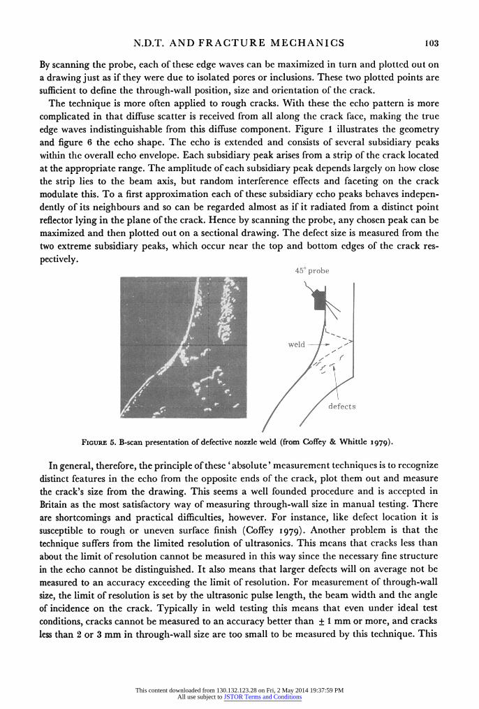
To assist in plotting the positions of defects relative to component surfaces, particularly when those surfaces are curved, several laboratories lhave developed 'B-scan' devices. In the portable B-scan developed at the C.E.G.B. (Harper et al. 1978), the ultrasonic probe, while still scanned manually, is attached to a pantograph, which measures its position and orientation by using potentiometers. The positional information controls the direction and position of the time base of a bistable storage oscilloscope. The echo amplitude is used to control the writing on the storage screen. As the probe is scanned, an ultrasonic cross section through the component is drawn on the screen. Figure 5 illustrates the display obtained from a defective nozzle weld. In addition to assisting in the location of defects, the B-scan system gives a permanent objective record and can also provide invaluable information to aid defect diagnosis and size measure- ment.
3.3. Accurate defect size measurement The techniques of defect size measurement and the philosophies of defect assessment by
ultrasonics have evolved independently in the different countries employing ultrasonics. As a result, there is no universally accepted 'correct' method. Indeed, our understanding of the interaction between ultrasound and defects is still too limited to allow the optimum methods to be described even in principle. All techniques in use are empirical to some extent and this is why several alternative methods are possible, each supported enthusiastically by its own protagonists. Broadly, however, we can distinguish two approaches to size measurement. First we can study in detail the ultrasonic echo from a defect as a function of probe position and hence attempt to diagnose its type and measure its size, in both dimensions, as accurately as possible. This approach is followed principally in Britain. Alternatively, without attempting to measure size precisely, we record some easily measured parameters of a defect, such as its echo amplitude and approximate length and/or depth. These are used as convenient labels to characterize the defect for assessment against Code requirements, the Codes being written in terms of these ultrasonic parameters. This approach is widely used in Europe, particularly in West Germany, and to a certain degree in the United States. The first, or 'absolute', approach to measurement is clearly the one that is most closely related to fracture mechanics since it sets out to determine precisely those defect dimensions relevant to defect growth and stability. This subsection out- lines the basic techniques in this category. Those falling into the second category above are less directly related to fracture mechanics, and we have termed them 'pseudo-sizing' techniques. They will be discussed in ? 3.4.
The example we have chosen to illustrate 'absolute' size measurement methods is the measurement of through-wall size of a large crack. Basically the technique is an extension of the procedure for plotting out small reflectors as described in the previous subsection. The principle is most clearly seen by considering an inclined beam of shear pulses obliquely incident on a smooth planar defect. Weak edge waves will be diffracted by the top and bottom crack tips, and if the crack is deep enough these will appear resolved as two pulses on the flaw detector screen. (The criterion for resolution has previously been discussed by Coffey & Whittle I979.)
This content downloaded from 130.132.123.28 on Fri, 2 May 2014 19:37:59 PMAll use subject to JSTOR Terms and Conditions
N.D.T. AND FRACTURE MECHANICS 103
By scanning the probe, each of these edge waves can be maximized in turn and plotted out on a drawing just as if they were due to isolated pores or inclusions. These two plotted points are sufficient to define the through-wall position, size and orientation of the crack.
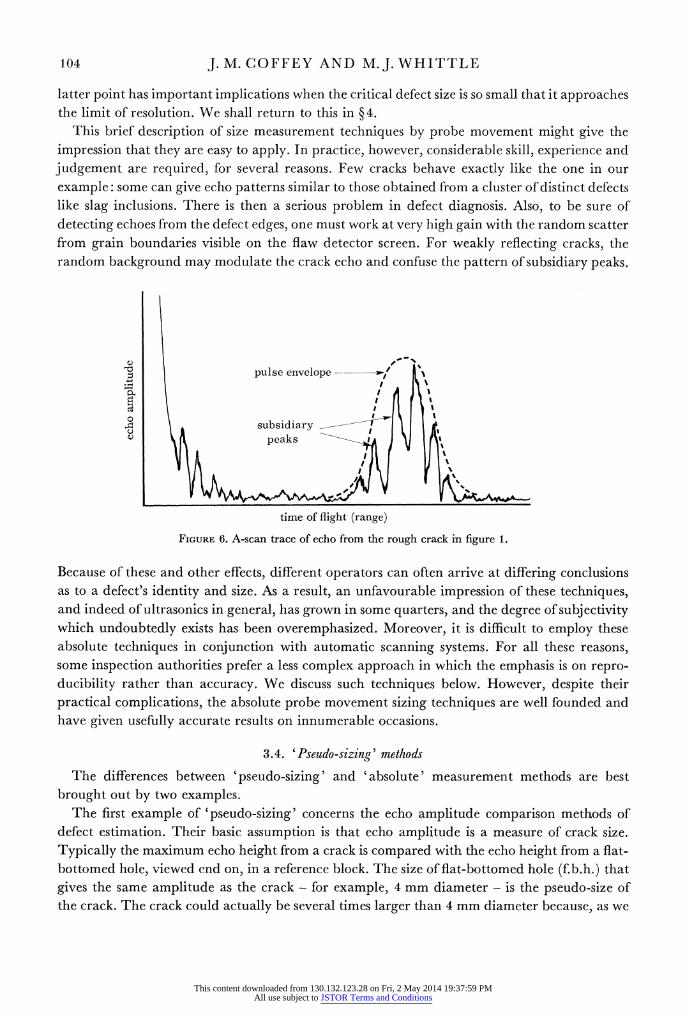
The technique is more often applied to rough cracks. With these the echio pattern is more complicated in that diffuse scatter is received from all along the crack face, making the true edge waves indistinguishable from this diffuse component. Figure 1 illustrates the geometry and figure 6 the echo shape. The echo is extended and consists of several subsidiary peaks within the overall echo envelope. Each subsidiary peak arises from a strip of the crack located at the appropriate range. The amplitude of each subsidiary peak depends largely on how close the strip lies to the beam axis, but random interference effects and faceting on the crack modulate this. To a first approximation each of these subsidiary echo peaks behaves indepen- dently of its neighbours and so can be regarded almost as if it radiated from a distinct point reflector lying in the plane of the crack. Hence by scanning the probe, any chosen peak can be maximized and then plotted out on a sectional drawing. The defect size is measured from the two extreme subsidiary peaks, which occur near the top and bottom edges of the crack res- pectively.
450 probe
weld-
defects
FIGURE 5. B-scan presentation of defective nozzle weld (from Coffey & Whittle 1979).
In general, therefore, the principle of these 'absolute' measurement techniques is to recognize distinct features in the echo from the opposite ends of the crack, plot them out and measure the crack's size from the drawing. This seems a well founded procedure and is accepted in Britain as the most satisfactory way of measuring through-wall size in manual testing. There are shortcomings and practical difficulties, however. For instance, like defect location it is susceptible to rough or uneven surface finish (Coffey 1979). Another problem is that the technique suffers from the limited resolution of ultrasonics. This means that cracks less than about the limit of resolution cannot be measured in this way since the necessary fine structure in the echo cannot be distinguished. It also means that larger defects will on average not be measured to an accuracy exceeding the limit of resolution. For measurement of through-wall size, the limit of resolution is set by the ultrasonic pulse length, the beam width and the angle of incidence on the crack. Typically in weld testing this means that even under ideal test conditions, cracks cannot be measured to an accuracy better than + 1 mm or more, and cracks less than 2 or 3 mm in through-wall size are too small to be measured by this technique. This
This content downloaded from 130.132.123.28 on Fri, 2 May 2014 19:37:59 PMAll use subject to JSTOR Terms and Conditions
104 J. M. COFFEY AND M.J. WHITTLE
latter point has important implications when the critical defect size is so small that it approaches the limit of resolution. We shall return to this in ? 4.
This brief description of size measurement techniques by probe movement might give the impression that they are easy to apply. In practice, however, considerable skill, experience and judgement are required, for several reasons. Few cracks behave exactly like the one in our example: some can give echo patterns similar to those obtained from a cluster of distinct defects like slag inclusions. There is then a serious problem in defect diagnosis. Also, to be sure of detecting echoes from the defect edges, one must work at very high gain with the random scatter from grain boundaries visible on the flaw detector screen. For weakly reflecting cracks, the random background may modulate the crack echo and confuse the pattern of subsidiary peaks.
V~~~~~~~~~~~~~~~~~~~~~~ pulse envelope A~'
subsidiary
time of flight (range)
FIGURE 6. A-scan trace of echo from the rough crack in figure 1.
Because of these and other effects, different operators can often arrive at differing conclusions as to a defect's identity and size. As a result, an unfavourable impression of these techniques, and indeed of ultrasonics in general, has grown in some quarters, and the degree of subjectivity which undoubtedly exists has been overemphasized. Moreover, it is difficult to employ these absolute techniques in conjunction with automatic scanning systems. For all these reasons, some inspection authorities prefer a less complex approach in which the emphasis is on repro- ducibility rather than accuracy. We discuss such techniques below. However, despite their practical complications, the absolute probe movement sizing techniques are well founded and have given usefully accurate results on innumerable occasions.
3.4. 'Pseudo-sizing' methods
The differences between 'pseudo-sizing' and 'absolute' measurement methods are best brought out by two examples.
The first example of 'pseudo-sizing' concerns the echo amplitude comparison methods of defect estimation. Their basic assumption is that echo amplitude is a measure of crack size. Typically the maximum echo height from a crack is compared with the echo height from a flat- bottomed hole, viewed end on, in a reference block. The size of flat-bottomed hole (f.b.h.) that gives the same amplitude as the crack - for example, 4 mm diameter - is the pseudo-size of the crack. The crack could actually be several times larger than 4 mm diameter because, as we
This content downloaded from 130.132.123.28 on Fri, 2 May 2014 19:37:59 PMAll use subject to JSTOR Terms and Conditions
N.D.T. AND FRACTURE MECHANICS 105
have seen, its echo might be weakened by unfavourable orientation or roughness on the crack faces. The equivalent flat-bottomed hole is a convenient way of expressing echo amplitudes, but one must beware of the temptation to treat the f.b.h. as an actual size (see, for example, International Institute of Welding I977).
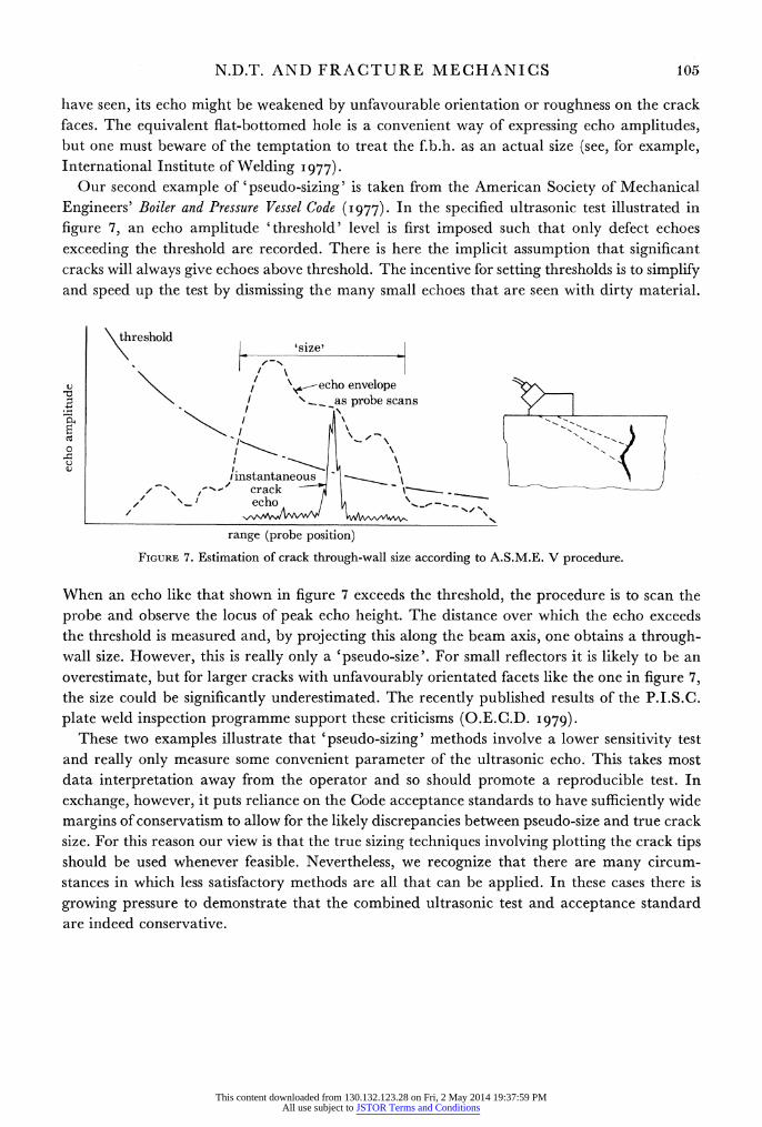
Our second example of 'pseudo-sizing' is taken from the American Society of Mechanical Engineers' Boiler and Pressure Vessel Code (i977). In the specified ultrasonic test illustrated in figure 7, an echo amplitude 'threshold' level is first imposed such that only defect echoes exceeding the threshold are recorded. There is here the implicit assumption that significant cracks will always give echoes above threshold. The incentive for setting thresholds is to simplify and speed up the test by dismissing the many small echoes that are seen with dirty material.
threshold 'size'
\echo envelope 4-
I \___as probescans
I instantaneous /\ ~~~ crack
echo
range (probe position)
FIGURE 7. Estimation of crack through-wall size according to A.S.M.E. V procedure.
When an echo like that shown in figure 7 exceeds the threshold, the procedure is to scan the probe and observe the locus of peak echo height. The distance over which the echo exceeds the threshold is measured and, by projecting this along the beam axis, one obtains a through- wall size. However, this is really only a 'pseudo-size'. For small reflectors it is likely to be an overestimate, but for larger cracks with unfavourably orientated facets like the one in figure 7, the size could be significantly underestimated. The recently published results of the P.I.S.C. plate weld inspection programme support these criticisms (O.E.C.D. I979).
These two examples illustrate that 'pseudo-sizing' methods involve a lower sensitivity test and really only measure some convenient parameter of the ultrasonic echo. This takes most data interpretation away from the operator and so should promote a reproducible test. In exchange, however, it puts reliance on the Code acceptance standards to have sufficiently wide margins of conservatism to allow for the likely discrepancies between pseudo-size and true crack size. For this reason our view is that the true sizing techniques involving plotting the crack tips should be used whenever feasible. Nevertheless, we recognize that there are many circum- stances in which less satisfactory methods are all that can be applied. In these cases there is growing pressure to demonstrate that the combined ultrasonic test and acceptance standard are indeed conservative.
This content downloaded from 130.132.123.28 on Fri, 2 May 2014 19:37:59 PMAll use subject to JSTOR Terms and Conditions
106 J. M. COFFEY AND M.J. WHITTLE
4. THE EFFECTIVE APPLICATION OF ULTRASONIC INSPECTION
Section 3 outlined the basic features of crack detection, measurement and assessment by ultrasonics. The main limitations and sources of error were also noted. We now build upon these basics to illustrate the interaction between component design and fracture mechanics and the effectiveness of ultrasonic inspection. In this we draw attention to three points that seem particularly important in ensuring that maximum benefit is obtained from ultrasonics.
4.1. Component design and inspectability
It is obvious that a component cannot be properly inspected by ultrasonics unless it is possible to scan ultrasonic beams through all the relevant volume and in the optimum directions for crack detection. Consequently, the component geometry has the greatest influence on whether full inspection is possible. An ill-placed bolt hole, attachment weld or change of section could prevent an ultrasonic probe's being placed to examine some critical region, and could thus introduce blind spots into the inspection. In such cases a fracture mechanics analysis may be obliged to assume a planar defect equal in size to the uninspected area. Unground weld caps also severely limit ultrasonic inspection by preventing any probe's being placed on top of the weld. It is then not possible to direct a beam along the welding direction to search for transverse cracking. The detection of longitudinal defects is also severely restricted, and cracks immediately under the cap could remain undetected. The reason is that the only way in which an ultrasonic beam can reach a defect in this position is by being reflected off the far wall of the component, up into the cap. However, many echoes are then also received from the rough cap and these could easily obscure the crack's echo. A further example is that it may not be possible to inspect a casting or weld satisfactorily for cracks if it contains a high density of pores or inclusions; these can give a confusing background of echoes, which effectively limit the testing sensitivity.
These examples illustrate two related points. First, where there are designs of equal engineer- ing quality, the one that allows the most inspection should be chosen. Secondly, it may be necessary to spend money on the use of higher quality materials and on having welds ground simply to ensure satisfactory inspection.
4.2. Consideration of defect likelihood
Our second point concerns those situations in which fracture mechanics is being used to set a defect acceptance standard, and hence the requirements for the non-destructive examination. In fracture mechanics one is at liberty to postulate notional planar defects of any size and aspect ratio in any position and orientation in the structure. N.d.t., however, is concerned with finding real defects. It would be quite unreasonable to insist on an inspection guaranteeing detection of every conceivable defect; even if such an inspection were possible, it would take a great deal of time. It is more realistic to look for an effective yet economical inspection that has a very high probability of detecting all the likely serious defects, and an acceptable probability of finding less likely ones. The nature of the primary defects to be detected therefore needs to be decided early in planning an inspection since this will dictate the appropriate n.d.t. technique. An example will illustrate this point.
Many fatigue cracks initiate at a free surface. If fatigue were judged to be the only con- ceivable crack growth mechanism, one might reasonably argue that a surface examination only would be sufficient. Cracks breaking accessible surfaces could then be detected by magnetic
This content downloaded from 130.132.123.28 on Fri, 2 May 2014 19:37:59 PMAll use subject to JSTOR Terms and Conditions
N.D.T. AND FRACTURE MECHANICS 107
particle or dye penetrant techniques, and in remote surfaces by 45? ultrasonic shear probes with the use of the corner effect of figure 4b. If, on the other hand, totally embedded fatigue cracks cannot be ruled out, it will probably be necessary to apply the two-probe tandem technique of figure 4c. As we have already mentioned, the reason for this is that fatigue cracks are smooth and cannot in general be detected with confidence in pulse-echo at oblique inci- dences. However, as figure 4c indicates, the tandem technique requires a jig to hold the probes
together and so is not suited to manual testing. Consequently, equipment development is required and the complexity of inspection escalates. Moreover, the tandem method can only
be applied where the wall thickness is constant; the development of a technique for detecting
mid-wall fatigue cracks at changes of section could be a lengthy process. This example illus- trates the need tojudge the likely positions and forms of defect, bearing in mind the consequences of failure, to avoid expensive over-inspection.
4.3. Defect acceptance standards
A few remarks are appropriate concerning the relation between defect acceptance standards and the limitations of n.d.t. These apply particularly to welds and castings. As noted in ?2.4, many defect acceptance standards have been written with radiography in mind as the inspec-
tion technique. Radiography is insensitive to cracks, and the standards recognize this by dis-
allowing any form of planar defect. Nowadays, however, ultrasonics is gradually replacing radiography, and this technique is very sensitive to cracks and other defects. A difficulty arises
because the resolution of ultrasonics is limited to only about 2 mm in the through-wall direc-
tion, which means that ultrasonics cannot distinguish cracks in this scale from other small but
harmless defects. Consequently an attempt to enforce traditional acceptance standards to the
letter by using ultrasonics could oblige one to take the pessimistic view that every unresolved
defect could be a crack and hence cause for repair. We believe that the way out of this predica- ment is not to reduce the sensitivity of the ultrasonics inspection, since this would increase the
risk of not detecting significant but weakly reflecting cracks, but to write realistic acceptance
standards by using fracture mechanics. Difficulties can, however, still be caused. When fracture
mechanics has predicted a critical crack size, it is usual to scale this down to give a safety
margin. However, if this factor is too conservative, one could again be expecting ultrasonics to
distinguish cracks only 2 or 3 mm in size from similarly small inclusions. The implication is that
the component design should be able to tolerate critical defects that are substantially larger than the limit of ultrasonic resolution.
4.4. Two examples of ultrasonic inspection
Finally we give two illustrative examples of the combined application of fracture mechanics
and ultrasonics. In cases where we can not wholly rely on previous experience for confidence in an ultrasonic
procedure, it may be necessary to build a model of the component containing artificial defects
to prove the inspection. An example of this approach has been reported by the National Vulcan
Engineering Insurance Group (I978). Briefly, a large chemical pressure vessel was to be re-
furbished after degeneration in service by replacing a forged nozzle. Because a large internal
structure containing catalyst could not be removed from the vessel, the usual hydraulic over- pressure test on completion of repairs could not be conducted. Instead, therefore, a combined fracture mechanics analysis and non-destructive inspection was chosen as the route to demon-
This content downloaded from 130.132.123.28 on Fri, 2 May 2014 19:37:59 PMAll use subject to JSTOR Terms and Conditions
108 J. M. COFFEY AND M.J.WHITTLE
strate vessel integrity. Since the repair was to be made during a limited planned outage, speed and reliability in the welding and n.d.t. were of the essence. Consequently a full-scale model of part of the vessel was made on which to train the welders and n.d.t. inspectors and to ensure that no unforeseen problems of access or equipment would delay the programme. The fracture mechanics assessment predicted critical defect sizes of order 5 mm, depending on position (W. G. Callister, private communication) and the proposed 100 % ultrasonic inspection procedure was verified by using test models containing machined slots to simulate defects. The likely orientation of certain possible lack-of-fusion defects required that a two-probe, tandem scan be performed in addition to the usual single probe, pulse-echo inspection. Because of this planning the whole repair programme went very smoothly. The use of fracture mechanics in conjunction with ultrasonics thus allowed the vessel to be returned quickly to service, with considerable cost savings.
A further notable example of the combined use of fracture mechanics and ultrasonics is provided by the development, in our laboratory, of an in-service inspection of certain com- ponents in the 1500 MW Dinorwic Pumped Storage Power Station. Here water is pumped from a lake to a second one 560 m higher during the night when demand for electricity is low. The water in the upper lake can then be used to generate power very quickly. The planned use of the Dinorwic plant involves as many as 20 starts and shutdowns per day, and these subject the plant to severe fatigue loadings. Fracture mechanics has been used to identify the components at highest risk. In parallel, the considerations set out in ?3 have been used to determine for each component the sizes and positions of defects that can be detected confidently by ultrasonics. On the assumption that a component could actually contain defects of these sizes, its residual life has been calculated. To provide a factor of safety the component will be inspected at intervals of one-fifth the calculated residual life. The time between inspections is thus different for the various areas of plant, reflecting both the different operational stress levels and the local problems of inspection.
The need to detect small crack growths by comparing results from successive inspections requires the full and accurate records that only an automatic probe scanning and data recording system can provide. The probe angles and configurations are dictated by the defects which are anticipated. Those lying at an angle to the accessible surface of the welds will be detected by using conventional 450 and 700 pulse-echo inspections. By the corner effect the 450 inspection will also detect cracks growing from either free surface. To allow for the possibility of mid-wall fatigue crack growth from welding defects that have escaped post-fabrication inspection, we have also included a tandem inspection. All ultrasonic echoes are displayed on B-scan storage oscilloscopes and recorded by automatically photographing the displays whenever a defect signal in any ultrasonic channel exceeds a threshold amplitude, which itself has been deter- mined by the considerations set out in ?3.
We have used analogue data recording techniques in this very critical and demanding application because extensive experience gives us confidence that no unexpected development difficulties are likely to occur. There is little doubt, however, that future applications of this type will rely increasingly on digital techniques because of their greater flexibility. The prospect, for example, of automatically measuring defect growth between successive inspections is an attractive one. Nevertheless, before the potential of digital systems can be fully exploited, we need a considerably better understanding of cracks and how they scatter ultrasound.
This content downloaded from 130.132.123.28 on Fri, 2 May 2014 19:37:59 PMAll use subject to JSTOR Terms and Conditions
N.D.T. AND FRACTURE MECHANICS 109
5. CONCLUSION
In this short review we have set forward some basic facts of non-destructive testing as it relates to component design and the fracture mechanics assessment of defects. Section 2 stressed the importance of dye penetrant, magnetic particle and eddy current methods for finding cracks in accessible surfaces. For detecting embedded or far surface cracking, however, these methods are not applicable and even radiography is poor. Rather, ultrasonics is the technique of choice since not only is it sensitive to cracks but it can measure their position, size and orientation.
Having focused on ultrasonics, we went on to outline the techniques by which ultrasonics is currently used to detect and measure cracks. A distinction was drawn between 'absolute' methods, which make an earnest attempt to measure the actual size as accurately as possible, and the 'pseudo-sizing' methods which really determine only a convenient parameter of the crack echo, loosely related to size, for use in Acceptance Codes. Small defects for which the ends cannot be resolved are difficult to measure and, as ? 4. 1 discussed, this implies that any accept- ance standard that requires cracks 2 or 3 mm in size to be distinguished from innocuous defects is likely to prove unworkable. In other paragraphs in ?4 we examined aspects of the relations between n.d.t., component design and fracture mechanics. In particular we emphasized the importance of 'design for inspection', and the need to state clearly the main types of defect that the inspection should aim to detect. Finally the review cited two cases in which fracture mechanics and ultrasonics have been profitably applied together.
In conclusion, ultrasonics is currently being developed and refined in many laboratories around the world to keep pace with the growing reliance being placed upon it as a crack detection and measurement technique. In future we expect the growing application of fracture mechanics and the growing use of ultrasonics to continue hand in hand.
This article is published by permission of the Director General, C.E.G.B. North Western Region.
REFERENCES (Coffey & Whittle) A.S.M.E. Boiler and Pressure Vessel Code I977 Section 5 (Non-destructive Examination), article 4. New York:
American Society of Mechanical Engineers. Betz, C. E. I966 Principles of magnetic particles. Oxford: Pergamon Press. Betz, C. E. I969 Principles of penetrants, 2nd edn. Chicago: Magnaflux Corp. Bezer, H. J. 197I Br. J. non-destr. Test. 13, 2-12. BS M35 1970 (Aerospace Series) Method for magnetic particle flaw detection of materials and components. London:
British Standards Institution. BS 2704 1978 Calibration blocksfor utse in ultrasonicflaw detection. London: British Standards Institution. BS 4331, part 1 1978 Assessing the performance characteristics of ultrasonic flaw detection equipment. London: British
Standards Institution. BS 5500 1976 Unfired fusion welded pressure vessels, table 5.7. London: British Standards Institution. Coffey, J. M. 1979 C.E.G.B. report no. NW/SSD/RR/85/79. Coffey, J. M. I980 In The measurement of crack length and shape during facture andfatigue (ed. C. J. Beevers).
Warley: E.M.A.S. Coffey, J. M., Oates, G. & Whittle, M. J. 1979 Phil. Trans. R. Soc. Lond. A 292, 285-298. Coffey, J. M. & Whittle, M. J. 1979 In Developments in pressure vessel technology (ed. R. W. Nichols), vol. 2, ch. 2.
London: Applied Science Publishers. Deane, J. A. 1978 In Proc. Symp. on Improving Reliability of Ultrasonic Inspection. London: British Inst. Non-destr.
Test. Dodd, C. V. 1977 In Research techniques in non-destructive testing (ed. R. S. Sharpe), vol. 3, ch. 13. Academic Press. Halmshaw, R. 1979 a In Developments in pressure vessel technology (ed. R. W. Nichols), vol. 2, ch. 1. London:
Applied Science Publishers.
This content downloaded from 130.132.123.28 on Fri, 2 May 2014 19:37:59 PMAll use subject to JSTOR Terms and Conditions
110 J. M. COFFEY AND M.J. WHITTLE
Halmshaw, R. I79 b Br. J. non-destr. Test. 21, 245-248. Halmshaw, R. & Hunt, C. A. I975 Br. J. non-destr. Test. 17, 71-75. Harper, H., Jones, H. M., Slinn, J. P. & Spinks, A. H. 1978 C.E.G.B. report no. NW/SSD/RR/8/78. Hislop, J. D. 1970 Br. J. non-destr. Test. 12, 42-51. International Institute of Welding 1977 Handbook of the ultrasonic examination of welds, ch. 7. Abington: The
Welding Institute. Krautkramer, J. & Krautkramer, H. 1977 Ultrasonic testing of materials, 2nd edn. Berlin: Springer-Verlag. Libby, H. I973 In Research techniques in non-destructive testing (ed. R. S. Sharpe), vol. 2, ch. 6. Academic Press. McMaster, R. C. (ed.) I963 iVon-destructive testing handbook. (2 volumes.) New York: Ronald Press. National Vulcan Engineering Insurance Group 1978 Vigilance 3 (8), 97-100. O.E.C.D. I979 Reportfrom the plate inspection steering committee on the ultrasonic examination of three test plates. Steering
Committee for Nuclear Energy, Paris, report no. SEN/SIN(79)13. Organization for Economic Cooperation and Development.
Smith, T. P. & Beech, H. G. I976 Br. J. non-destr. Test. 18, 137-143. Wooldridge, A. B. 1979 C.E.G.B. report no. NW/SSD/RR/42/79. Yokota, 0. & Ishu, Y. 1979 Br. J. non-destr. Test. 21, 239-244.
This content downloaded from 130.132.123.28 on Fri, 2 May 2014 19:37:59 PMAll use subject to JSTOR Terms and Conditions