Embed Size (px)
Citation preview
INTRODUCTION
Reliability and long service life are the basicrequirements when materials are introduced into theiroperational life. In order to achieve successful perform-ance a suitable combination of physical, chemical andmechanical properties is needed. In the case of ceramicmaterials under mechanical and thermal loads the situa-tion is complicated due to their low fracture resistance.However there are applications where exclusively suchmaterials can be used. The typical example are refracto-ry materials that are used broadly in many industrialbranches [1]. In this case thermal stability and accept-able thermal shock resistance together with satisfactorymechanical properties are the key requirements on thematerial. To meet these demands composite materialsare developed. The design of ceramic-based compositematerials leads to the development of multi-componentsystems where each constituent has a specific functionin the material. Examples of such composite systemsare the cordierite-mullite refractory materials investi-gated in a number of investigations [2-5].
Cordierite and mullite are ceramic materials suit-able for high temperature refractory components withgood chemical resistance [3, 6]. Their target applicationis in furnaces for use at temperatures >1000 °C.Cordierite has a superior thermal stability, thermalshock resistance and low thermal expansion coefficient.On the contrary the mechanical properties are ratherinferior and are the limiting factor for some of the
envisaged applications [7]. Mullite has superiormechanical properties at both room and elevated tem-peratures but its thermal shock resistance is low and thethermal expansion coefficient is higher comparing tocordierite. An overview of typical basic properties ofcordierite and mullite is given in table 1. The ceramicmulti-component composite material could exhibit theadvantages of its constituents when the componentshave optimised properties and they are mixed in theproper ratio.
Notwithstanding the promise of enhanced perform-ance of cordierite-mullite refractories for fast firingapplications [4], there is a current lack of understandingconcerning the effect of microstructural features on theoverall performance of the cordierite-mullite refractorycomposite, especially under severe in-service condi-tions, i.e. at elevated temperatures and under thermalshock loading [5].
Two commercially available systems of cordierite-mullite refractory materials have been evaluated in thispaper. In particular, the materials were subjected torepetitive thermal shocks by the water-quench tech-nique and subsequently the fracture toughness was eval-uated using a Chevron notched specimen techniqueaccompanied by an acoustic emission measurementmonitoring crack propagation. The aim of the paper wasto investigate fracture behaviour of both refractorymaterials tested, mainly from point of view of materialconstituent's effect on damage and crack developmentupon thermal shock loading.
Original papers
Ceramics − Silikáty 50 (4) 245-250 (2006) 245
FRACTURE BEHAVIOUR OF REFRACTORY CERAMICSAFTER CYCLIC THERMAL SHOCK
ZDENÌK CHLUP, DINO N. BOCCACCINI*, CRISTINA LEONELLI*,MARCELLO ROMAGNOLI*, ALDO R. BOCCACCINI**
Institute of Physics of Materials, Academy of Sciences, Zizkova 22, 616 62, Brno, Czech Republic*Dipartimento di Ingegneria dei Materiali e dell'Ambiente, Universita di Modena e Reggio Emilia, 41100 Modena, Italy
**Department of Materials, Imperial College, London SW7 2BP, United Kingdom
E-mail: [email protected]
Submitted January 31, 2006; accepted August 9, 2006
Keywords: Cordierite-mullite composite, Refractory materials, Chevron notch, Fracture toughness
Two commercially available refractory ceramic materials primary used as substrates for fast firing of porcelain stonewarewere investigated. The first one, commercially known as CONC, contains cordierite and mullite in the ratio 50:50. The REFOrefractory composite material with coarser microstructure compared to CONC has a cordierite-to-mullite ratio of 50:45 andthe balance is filled by quartz. Both materials were exposed to water-quench tests from 1250°C, applying various numbers ofthermal cycles (shocks). Subsequently the fracture toughness was evaluated on both as-received and shocked samples usingthe Chevron notched specimen technique. The results were analysed with respect to the microstructure damage caused by thethermal loading. Scanning electron microscopy was used to analyse both microstructure and fracture surfaces in samples withdifferent thermal loading history.
EXPERIMENTAL
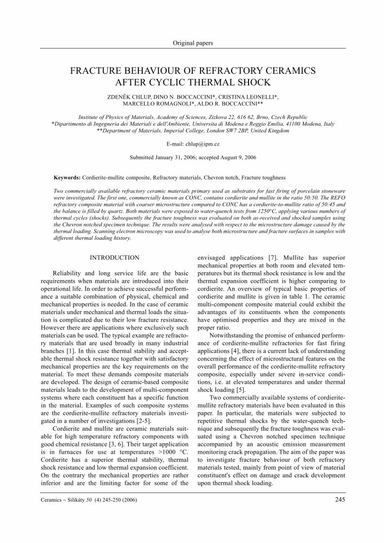
Two commercially available refractory ceramiccomposite materials known as CONC and REFO (inplate form) were selected for the investigation. The firstone was the fine grained CONC composite havingcordierite/mullite composition in ratio 50:50 and thesecond one was the coarse grained REFO compositeformed by 45 wt.% of cordierite, 50 wt.% of mullite and5 wt.% of SiO2 in the quartz form. The density of thecomposite in the bulk form was determined for CONCon the level of 1.8947 g/cm3 and for REFO on the levelof 1.8781 g/cm3, which leads to porosity of 28 % and26 %, respectively. The porosity measurements wereconfirmed by the SEM micrographs analysis using anImage Pro Plus software. The microstructure of as-received materials is shown in figure 1. There is no vis-ible difference between cordierite and mullite due tosimilar chemical composition, however it was detectedby detailed analysis that bigger grains (white in day-light) are mullite grains and the smaller grains (brownin daylight) belong to cordierite, the detailed micro-structural investigation of these materials was publishedelsewhere [5].
Suitable samples for thermal shock tests byquenching of dimensions 20×5×40 mm were cut fromthe plates and subjected to various numbers of thermalshock cycles. Each thermal shock cycle consisted ofseveral consequent steps. Slow heating up by a nominalheating speed of 10°C/min to the quench temperatureset at 1250°C, holding at this temperature for 30 minu-tes to reach thermal equilibrium in the whole specimenvolume and finally quenching into a water bath at tem-perature of 25°C. Samples of both CONC and REFOmaterials were thermally cycled up to 30 cycles.
Subsequently both as-received and thermallyshocked samples were cut by a precise diamond saw tothe shape of bars with rectangular cross-section of3×4 mm recommended for fracture toughness test byASTM standard [10]. The Chevron Notch Techniquewas used for fracture toughness determination. ThreeChevron Notches with top angle of 90° were introducedinto each bar using an ultra thin diamond blade by usinga precision saw Isomet 5000. This technique wasapplied to achieve the best utilisation of the availablematerial. The reliability of this approach was describedelsewhere [11, 12]. A universal testing system Instron8862 equipped with three point bend test fixtures with
Chlup Z., Boccaccini D. N., Leonelli C., Romagnoli M., Boccaccini A. R.
246 Ceramics − Silikáty 50 (4) 245-250 (2006)
Figure 1. Typical SEM microstructures of CONC (a) and REFO (b) materials (backscattered electron images).
a) b)
Table 1. Typical values of selected properties of dense constituents used in refractory materials investigated [8, 9].
Cordierite Mullite α-Quartz
Chemical Formula 2MgO-2Al2O3-5SiO2 3Al2O3-SiO2 SiO2
Density (g/cm3) 2.60 2.80 2.65Modulus of Elasticity (GPa) 70 150 70Poisson's Ratio 0.21 0.25 0.17Compressive strength (MPa) 350 551 650Tensile strength (MPa) 25.5 103.5 48Bending strength (MPa) 117 170 80Fracture Toughness (MPam1/2) - 2 -Linear Thermal Expansion Coefficient (10-6 K-1) 1.7 5.3 0.45Thermal Shock Resistence (°C) 500 300 1400
span of 16 mm was used to apply the loading. A cross-head speed of 10 µm/min was used in all tests to achieveslow crack propagation during loading. An inductiveextensometer was used for deflection measurement andforce-deflection curves were recorded. Monitoring offracture behaviour, mainly crack initiation and subse-quently propagation during loading was performed byacoustic emission measurement. The fracture toughnessvalues were calculated from the maximum force evalu-ated from the force-deflection curve and the specimendimensions by the following equation:
where Y*min is the minimum of geometrical compli-
ance function Y*. In this work a calculation of the geo-metrical compliance function based on the Bluhm'sslice model was used [13], the details of the applied pro-cedures have been described elsewhere [14].
Scanning electron microscopy was employed forboth microstructural and fractographical analyses.These analyses facilitate the explanation of fracturebehaviour of each material under investigation in thecontext of microstructural changes caused by cyclicthermal shock.
RESULTS AND DISCUSSION
The experimental materials used in this investiga-tion were characterised from the point of view of theirthermal shock resistance. As-received as well as ther-mally loaded samples after 7, 15 and 30 thermal shockswere compared. The fracture toughness as a possiblecriterion for quantifying microstructural damage causedby the cyclic thermal shock loading was investigated in
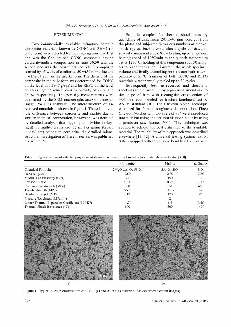
this contribution. The Chevron Notch Techniquetogether with an acoustic emission measurement wasused to achieve this aim. A typical example of a loadingtrace suitable for fracture toughness determination isshown in figure 2a, where the full line represents therecorded force-deflection data and the dashed line indi-cates the cumulative number of acoustic emissioncounts (events) in the corresponding deflection (time)scale. Figure 2b is an example of an invalid loadingtrace due to the absence of slow crack propagation (pos-sibly due to geometrical and/or microstructural reasons)for the REFO material.
A smooth maximum force necessary for fracturetoughness determination did not occur in the loadingtrace and therefore the fracture toughness value wouldnot be valid. It is evident from the fractographicalanalysis of fracture surfaces that in this case a largeround mullite grain was placed in the vicinity of theChevron tip. This grain most probably stopped the initi-ated crack and crack propagation continued trough thegrain boundary after sufficient accumulation of elasticenergy. The overestimated fracture toughness value ofthis sample would be 0.56 MPam0.5 which is nearly45 % above the average of the data set for 7 thermalshocks (see below). Even from the curve of cumulativeAE counts it is evident that no crack propagation occursbefore reaching the maximum force and then uncon-trolled crack propagation starts. On the other hand thesmooth onset of acoustic emission counts can be seenin case of the valid test (figure 2a), however the gainand noise level is dependent on the setting of acousticemission measurement system and could vary fromsample to sample. Other mechanical properties such asYoung's modulus and brittleness index were alsosubjected to investigation and the corresponding resultsare analysed in detail elsewhere [15, 16].
Fracture behaviour of refractory ceramics after cyclic thermal shock
Ceramics − Silikáty 50 (4) 245-250 (2006) 247
0 5 10 15 20 25 30 35 40 45 50 55deflection (mm)
0
1
2
3
4
5
6
7
8
9
10
load
(N)
0
1×10⁴
2×10⁴
3×10⁴
4×10⁴
5×10⁴
AE
cou
nt
loading traceAE count trace
REFO
0 5 10 15 20 25 30 35 40 45 50deflection (mm)
0
2
4
6
8
10
12
14
16
18
20
load
(N)
0
1×10⁴
2×10⁴
3×10⁴
4×10⁴
5×10⁴
AE
cou
nt
loading traceAE count trace
REFO
6×10⁴
7×10⁴
Figure 2. Typical loading traces for valid (a) and invalid (b) fracture toughness test of REFO composite. Also AE count traces areshown.
a) b)
K FB W
YIC = maxmin*
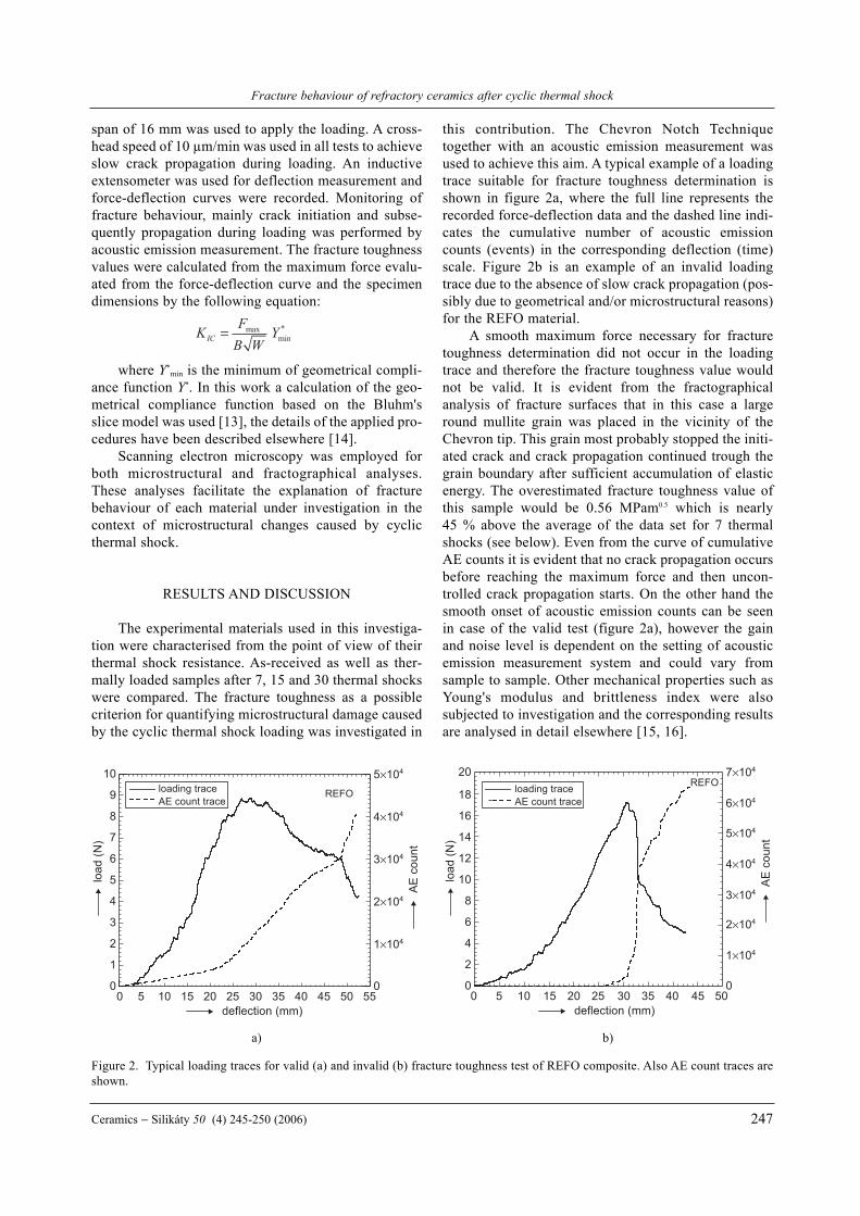
All valid fracture toughness data obtained duringtesting of both CONC and REFO refractory materialsare plotted in figure 3. The relatively low level fracturetoughness values were accompanied by a large scatter.All groups of test pieces exhibit high scatter independ-ently of the number of thermal cycles. This behaviour isclosely connected with the inhomogeneous and coarse-grained microstructure and/or the presence of pores inthe materials under investigation [5]. The basic statisti-cal characteristics of each test group are summarised intable 2.
The average fracture toughness value for CONCmaterial in as-received state is 0.34 MPam0.5 and forREFO material 0.39 MPam0.5. After 7 thermal cycles theREFO material stays on the same level of fracturetoughness, on the contrary the CONC material exhibitsa slight decrease by about 0.1 MPam0.5. This differencein fracture behaviour can be explained by the positiverole of the low silicate content in the REFO material.This component is partially melted during heating up tothe quenching temperature which could lead to crack tipblunting or possibly to some kind of crack healing.However this mechanism is not inexhaustible and there-fore when more than 7 thermal shock cycles are appliedthe average fracture toughness values drop to nearly thesame level as the value obtained for CONC refractorymaterial. It is measurable that the REFO material hashigher scatter than CONC material. The higher scatterin fracture toughness data is due to a coarser
microstructure. Generally defects as microcracks, poresand decohesion of grains are present even in themicrostructure of as-received samples and there areimposed by the fabrication technology.
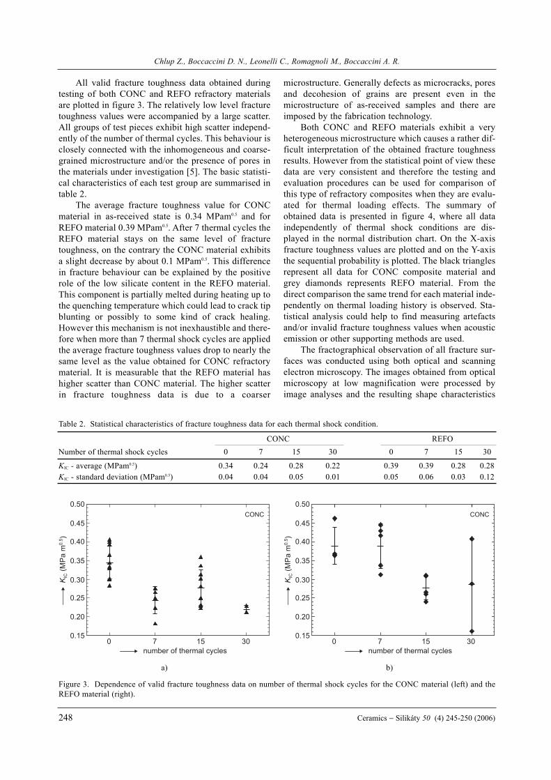
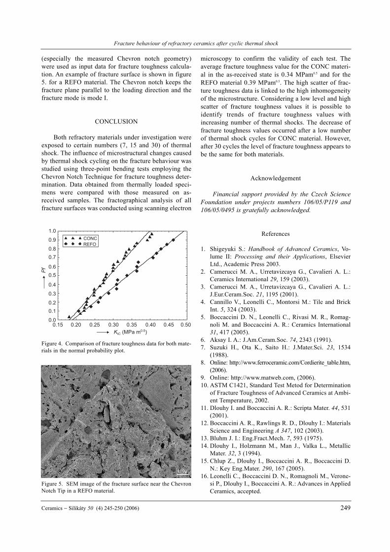
Both CONC and REFO materials exhibit a veryheterogeneous microstructure which causes a rather dif-ficult interpretation of the obtained fracture toughnessresults. However from the statistical point of view thesedata are very consistent and therefore the testing andevaluation procedures can be used for comparison ofthis type of refractory composites when they are evalu-ated for thermal loading effects. The summary ofobtained data is presented in figure 4, where all dataindependently of thermal shock conditions are dis-played in the normal distribution chart. On the X-axisfracture toughness values are plotted and on the Y-axisthe sequential probability is plotted. The black trianglesrepresent all data for CONC composite material andgrey diamonds represents REFO material. From thedirect comparison the same trend for each material inde-pendently on thermal loading history is observed. Sta-tistical analysis could help to find measuring artefactsand/or invalid fracture toughness values when acousticemission or other supporting methods are used.
The fractographical observation of all fracture sur-faces was conducted using both optical and scanningelectron microscopy. The images obtained from opticalmicroscopy at low magnification were processed byimage analyses and the resulting shape characteristics
Chlup Z., Boccaccini D. N., Leonelli C., Romagnoli M., Boccaccini A. R.
248 Ceramics − Silikáty 50 (4) 245-250 (2006)
0 7 15 30number of thermal cycles
0.15
0.20
0.25
0.30
0.35
0.40
0.45
0.50CONC
0 7 15 30number of thermal cycles
0.15
0.20
0.25
0.30
0.35
0.40
0.45
0.50CONC
Figure 3. Dependence of valid fracture toughness data on number of thermal shock cycles for the CONC material (left) and theREFO material (right).
a) b)
Table 2. Statistical characteristics of fracture toughness data for each thermal shock condition.
CONC REFONumber of thermal shock cycles 0 7 15 30 0 7 15 30
KIC - average (MPam0.5) 0.34 0.24 0.28 0.22 0.39 0.39 0.28 0.28KIC - standard deviation (MPam0.5) 0.04 0.04 0.05 0.01 0.05 0.06 0.03 0.12
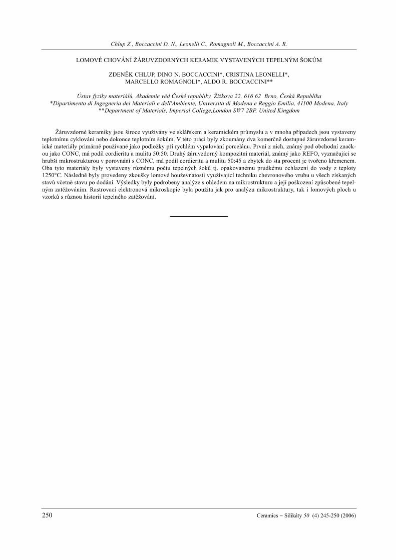
(especially the measured Chevron notch geometry)were used as input data for fracture toughness calcula-tion. An example of fracture surface is shown in figure5. for a REFO material. The Chevron notch keeps thefracture plane parallel to the loading direction and thefracture mode is mode I.
CONCLUSION
Both refractory materials under investigation wereexposed to certain numbers (7, 15 and 30) of thermalshock. The influence of microstructural changes causedby thermal shock cycling on the fracture behaviour wasstudied using three-point bending tests employing theChevron Notch Technique for fracture toughness deter-mination. Data obtained from thermally loaded speci-mens were compared with those measured on as-received samples. The fractographical analysis of allfracture surfaces was conducted using scanning electron
microscopy to confirm the validity of each test. Theaverage fracture toughness value for the CONC materi-al in the as-received state is 0.34 MPam0.5 and for theREFO material 0.39 MPam0.5. The high scatter of frac-ture toughness data is linked to the high inhomogeneityof the microstructure. Considering a low level and highscatter of fracture toughness values it is possible toidentify trends of fracture toughness values withincreasing number of thermal shocks. The decrease offracture toughness values occurred after a low numberof thermal shock cycles for CONC material. However,after 30 cycles the level of fracture toughness appears tobe the same for both materials.
Acknowledgement
Financial support provided by the Czech ScienceFoundation under projects numbers 106/05/P119 and106/05/0495 is gratefully acknowledged.
References
1. Shigeyuki S.: Handbook of Advanced Ceramics, Vo-lume II: Processing and their Applications, ElsevierLtd., Academic Press 2003.
2. Camerucci M. A., Urretavizcaya G., Cavalieri A. L.:Ceramics International 29, 159 (2003).
3. Camerucci M. A., Urretavizcaya G., Cavalieri A. L.:J.Eur.Ceram.Soc. 21, 1195 (2001).
4. Cannillo V., Leonelli C., Montorsi M.: Tile and BrickInt. 5, 324 (2003).
5. Boccaccini D. N., Leonelli C., Rivasi M. R., Romag-noli M. and Boccaccini A. R.: Ceramics International31, 417 (2005).
6. Aksay I. A.: J.Am.Ceram.Soc. 74, 2343 (1991). 7. Suzuki H., Ota K., Saito H.: J.Mater.Sci. 23, 1534
(1988).8. Online: http://www.ferroceramic.com/Cordierite_table.htm,
(2006).9. Online: http://www.matweb.com, (2006).10. ASTM C1421, Standard Test Metod for Determination
of Fracture Toughness of Advanced Ceramics at Ambi-ent Temperature, 2002.
11. Dlouhy I. and Boccaccini A. R.: Scripta Mater. 44, 531(2001).
12. Boccaccini A. R., Rawlings R. D., Dlouhy I.: MaterialsScience and Engineering A 347, 102 (2003).
13. Bluhm J. I.: Eng.Fract.Mech. 7, 593 (1975).14. Dlouhy I., Holzmann M., Man J., Valka L., Metallic
Mater. 32, 3 (1994). 15. Chlup Z., Dlouhy I., Boccaccini A. R., Boccaccini D.
N.: Key Eng.Mater. 290, 167 (2005). 16. Leonelli C., Boccaccini D. N., Romagnoli M., Verone-
si P., Dlouhy I., Boccaccini A. R.: Advances in AppliedCeramics, accepted.
Fracture behaviour of refractory ceramics after cyclic thermal shock
Ceramics − Silikáty 50 (4) 245-250 (2006) 249
0.15 0.20 0.25 0.30 0.35 0.40 0.450.0
0.10.2
0.3
0.4
0.50.6
0.70.8
0.9
1.0
REFO
0.50
CONC
Figure 4. Comparison of fracture toughness data for both mate-rials in the normal probability plot.
Figure 5. SEM image of the fracture surface near the ChevronNotch Tip in a REFO material.
Chlup Z., Boccaccini D. N., Leonelli C., Romagnoli M., Boccaccini A. R.
250 Ceramics − Silikáty 50 (4) 245-250 (2006)
LOMOVÉ CHOVÁNÍ ŽÁRUVZDORNÝCH KERAMIK VYSTAVENÝCH TEPELNÝM ŠOKÙM
ZDENÌK CHLUP, DINO N. BOCCACCINI*, CRISTINA LEONELLI*,MARCELLO ROMAGNOLI*, ALDO R. BOCCACCINI**
Ústav fyziky materiálù, Akademie vìd Èeské republiky, Žižkova 22, 616 62 Brno, Èeská Republika*Dipartimento di Ingegneria dei Materiali e dell'Ambiente, Universita di Modena e Reggio Emilia, 41100 Modena, Italy
**Department of Materials, Imperial College,London SW7 2BP, United Kingdom
Žáruvzdorné keramiky jsou široce využívány ve skláøském a keramickém prùmyslu a v mnoha pøípadech jsou vystavenyteplotnímu cyklování nebo dokonce teplotním šokùm. V této práci byly zkoumány dva komerènì dostupné žáruvzdorné keram-ické materiály primárnì používané jako podložky pøi rychlém vypalování porcelánu. První z nich, známý pod obchodní znaèk-ou jako CONC, má podíl cordieritu a mulitu 50:50. Druhý žáruvzdorný kompozitní materiál, známý jako REFO, vyznaèující sehrubší mikrostrukturou v porovnání s CONC, má podíl cordieritu a mulitu 50:45 a zbytek do sta procent je tvoøeno køemenem.Oba tyto materiály byly vystaveny rùznému poètu tepelných šokù tj. opakovanému prudkému ochlazení do vody z teploty1250°C. Následnì byly provedeny zkoušky lomové houževnatosti využívající techniku chevronového vrubu u všech získanýchstavù vèetnì stavu po dodání. Výsledky byly podrobeny analýze s ohledem na mikrostrukturu a její poškození zpùsobené tepel-ným zatìžováním. Rastrovací elektronová mikroskopie byla použita jak pro analýzu mikrostruktury, tak i lomových ploch uvzorkù s rùznou historií tepelného zatìžování.