Embed Size (px)
Citation preview

FR-A8NCE INSTRUCTION M
ANUAL
C
INVERTER
INVERTER
PRE-OPERATION INSTRUCTIONS 1INSTALLATION 2WIRING 3INVERTER SETTING 4FUNCTION OVERVIEW 5I/O SIGNAL LIST 6DETAILS OF I/O SIGNALS 7PROGRAMMING EXAMPLES 8
INVERTERPlug-in option
INSTRUCTION MANUAL
HEAD OFFICE: TOKYO BUILDING 2-7-3, MARUNOUCHI, CHIYODA-KU, TOKYO 100-8310, JAPAN
FR-A8NCE
Network communication function
IB(NA)-0600509ENG-C(1802) MEE Printed in Japan Specifications subject to change without notice.
1
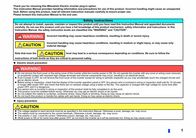
Thank you for choosing this Mitsubishi Electric inverter plug-in option.This Instruction Manual provides handling information and precautions for use of this product. Incorrect handling might cause an unexpected
.
tion Manual and appended documents ty information and instructions. In this
or severe injury.
m or slight injury, or may cause only
conditions. Be sure to follow the
he inverter with any cover or wiring cover removed, lectrical shock.u may accidentally touch the charged circuits and
ved in wiring or inspection shall wait for 10 minutes s charged with high voltage for some time after
ric shock.
, etc. may occur.
so may cause a burn.
fault. Before using this product, read all relevant instruction manuals carefully to ensure proper usePlease forward this Instruction Manual to the end user.
Electric shock prevention
Injury prevention
Safety instructionsDo not attempt to install, operate, maintain or inspect this product until you have read this Instruccarefully. Do not use this product until you have a full knowledge of this product mechanism, safeInstruction Manual, the safety instruction levels are classified into "WARNING" and "CAUTION".
Incorrect handling may cause hazardous conditions, resulting in death
Incorrect handling may cause hazardous conditions, resulting in mediumaterial damage.
Note that even the level may lead to a serious consequence depending on
instructions of both levels as they are critical to personnel safety.
WARNING Do not remove the front cover or the wiring cover of the inverter while the inverter power is ON. Do not operate t
as accidental contact with exposed high-voltage terminals and internal components may occur, resulting in an e Even if power is OFF, do not remove the front cover of the inverter except for wiring or periodic inspection as yo
get an electric shock. Before wiring or inspection, check that the display of the inverter operation panel is OFF. Any person who is invol
or longer after power OFF and check that there are no residual voltage using a tester or the like. The capacitor ipower OFF, and it is dangerous.
Any person who is involved in wiring or inspection of this product shall be fully competent to do the work. This product must be installed before wiring. Otherwise you may get an electric shock or be injured. Do not subject the cables to scratches, excessive stress, heavy loads or pinching. Doing so may cause an elect Do not touch this product or handle the cables with wet hands. Doing so may cause an electric shock.
CAUTION The voltage applied to each terminal must be as specified in the Instruction Manual. Otherwise a burst, damage The cables must be connected to the correct terminals. Otherwise a burst, damage, etc. may occur. The polarity (+ and -) must be correct. Otherwise a burst, damage, etc. may occur. While power is ON or for some time after power OFF, do not touch the inverter as it will be extremely hot. Doing
WARNING
CAUTION
CAUTION

Additional instructionsThe following instructions must be also followed. If this product is handled incorrectly, it may cause unexpected fault, an injury, or an electric
ents or other flammable substance such as oil.t wooden packages, infiltrate into this product, the ckaging, or use an alternative sterilization or
o be performed before packing the product.
to make unexpected motions.
a failure or damage of this product.
ed parameters for operation of the inverter and this
you touch this product.
Ensure all covers and safety guards are properly
2
shock.
CAUTIONTransportation and installation Do not stand or place heavy objects on this product. The installing orientation of this product must be correct. Do not install or operate this product if it is damaged or has parts missing. Foreign conductive objects must be prevented from entering the inverter. That includes screws and metal fragm If halogen-based materials (fluorine, chlorine, bromine, iodine, etc.), included in fumigants to sterilize or disinfec
product may be damaged. Prevent residual fumigant components from being infiltrated into the product when padisinfection method (heat disinfection, etc.). Note that sterilization or disinfection of wooden package should als
Test operation Before starting operation, confirm or adjust the parameter settings. Failure to do so may cause some machines
WARNINGUsage Do not modify this product. Do not remove any part which is not instructed to be removed in the Instruction Manuals. Doing so may lead to
CAUTIONUsage As all parameters return to their initial values after Parameter clear or All parameter clear is performed, the need
product must be set again before the operation is started. To avoid damage to this product due to static electricity, static electricity in your body must be discharged beforeMaintenance, inspection and parts replacement Do not carry out a megger (insulation resistance) test.Disposal This product must be treated as industrial waste.
General instruction For clarity purpose, illustrations in this Instruction Manual may be drawn with covers or safety guards removed.
installed prior to starting operation.
3
6
..............................................................6
..............................................................7
..............................................................9
10
............................................................10
............................................................11
15
............................................................15
............................................................16
............................................................17
................................................................ 17
................................................................ 17
............................................................18
................................................................ 18
................................................................ 20
23
............................................................23
............................................................25................................................................ 25............................................................289) .......................................................... 28
................................................................ 33
............................................................34
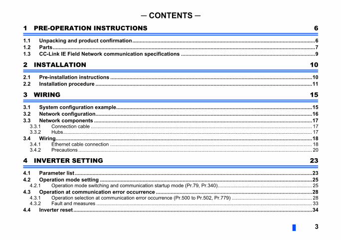
─ CONTENTS ─1 PRE-OPERATION INSTRUCTIONS
1.1 Unpacking and product confirmation..............................................................1.2 Parts....................................................................................................................1.3 CC-Link IE Field Network communication specifications .............................
2 INSTALLATION
2.1 Pre-installation instructions .............................................................................2.2 Installation procedure .......................................................................................
3 WIRING
3.1 System configuration example.........................................................................3.2 Network configuration.......................................................................................3.3 Network components ........................................................................................
3.3.1 Connection cable ................................................................................................3.3.2 Hubs....................................................................................................................
3.4 Wiring..................................................................................................................3.4.1 Ethernet cable connection ..................................................................................3.4.2 Precautions .........................................................................................................
4 INVERTER SETTING
4.1 Parameter list .....................................................................................................4.2 Operation mode setting ....................................................................................
4.2.1 Operation mode switching and communication startup mode (Pr.79, Pr.340)....4.3 Operation at communication error occurrence ..............................................
4.3.1 Operation selection at communication error occurrence (Pr.500 to Pr.502, Pr.774.3.2 Fault and measures ............................................................................................
4.4 Inverter reset ......................................................................................................
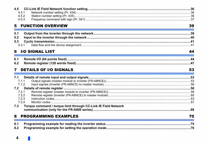
4.5 CC-Link IE Field Network function setting ..................................................................................................................36................................................................ 36................................................................ 36................................................................ 37
39
............................................................39
............................................................40
............................................................41
................................................................ 41
44
............................................................44
............................................................47
53
............................................................53
................................................................ 53
................................................................ 56
............................................................58
................................................................ 58
................................................................ 60
................................................................ 63
................................................................ 67
............................................................68
70
............................................................75
............................................................76
4
4.5.1 Network number setting (Pr. 434) .......................................................................4.5.2 Station number setting (Pr. 435) .........................................................................4.5.3 Frequency command with sign (Pr. 541) ............................................................
5 FUNCTION OVERVIEW
5.1 Output from the inverter through the network................................................5.2 Input to the inverter through the network .......................................................5.3 Cyclic transmission...........................................................................................
5.3.1 Data flow and link device assignment.................................................................
6 I/O SIGNAL LIST
6.1 Remote I/O (64 points fixed) .............................................................................6.2 Remote register (128 words fixed) ...................................................................
7 DETAILS OF I/O SIGNALS
7.1 Details of remote input and output signals.....................................................7.1.1 Output signals (master module to inverter (FR-A8NCE))....................................7.1.2 Input signals (inverter (FR-A8NCE) to master module) ......................................
7.2 Details of remote register .................................................................................7.2.1 Remote register (master module to inverter (FR-A8NCE)) .................................7.2.2 Remote register (inverter (FR-A8NCE) to master module) .................................7.2.3 Instruction codes.................................................................................................7.2.4 Monitor codes .....................................................................................................
7.3 Torque command / torque limit through CC-Link IE Field Network communication (only for the FR-A800 series) ................................................
8 PROGRAMMING EXAMPLES
8.1 Programming example for reading the inverter status ..................................8.2 Programming example for setting the operation mode.................................
5
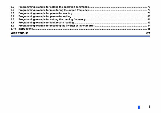
8.3 Programming example for setting the operation commands....................................................................................77............................................................78............................................................79............................................................80............................................................81............................................................83............................................................84............................................................85
87
8.4 Programming example for monitoring the output frequency........................8.5 Programming example for parameter reading................................................8.6 Programming example for parameter writing .................................................8.7 Programming example for setting the running frequency ............................8.8 Programming example for fault record reading .............................................8.9 Programming example for resetting the inverter at inverter error................8.10 Instructions ........................................................................................................
APPENDIX
duct is as you ordered and intact.
tates.
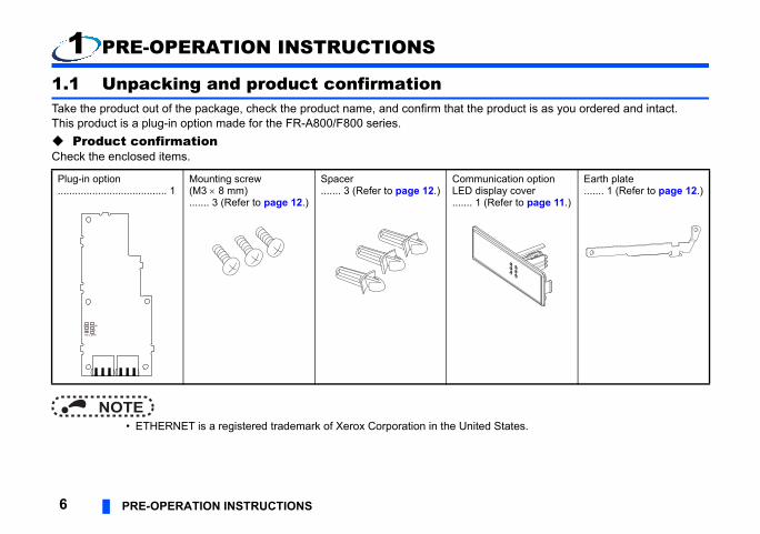
ation option y coverfer to page 11.)
Earth plate....... 1 (Refer to page 12.)
6 PRE-OPERATION INSTRUCTIONS
1 PRE-OPERATION INSTRUCTIONS
1.1 Unpacking and product confirmationTake the product out of the package, check the product name, and confirm that the proThis product is a plug-in option made for the FR-A800/F800 series. Product confirmationCheck the enclosed items.
NOTE • ETHERNET is a registered trademark of Xerox Corporation in the United S
Plug-in option ...................................... 1
Mounting screw (M3 8 mm)....... 3 (Refer to page 12.)
Spacer....... 3 (Refer to page 12.)
CommunicLED displa....... 1 (Re
RUN D LINK
SD ERR
RD L.ERR
ERATION INSTRUCTIONS 7
1
n Refer to page
serting a mounting screw or a 12
e network. 18e network. 18f the inverter by turning ON or 8
onnector on the inverter. 12
(e)
(a)
(a)
(a)
PRE-OP
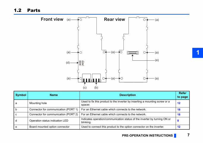
1.2 Parts
Symbol Name Descriptio
a Mounting hole Used to fix this product to the inverter by inspacer.
b Connector for communication (PORT 1) For an Ethernet cable which connects to th
c Connector for communication (PORT 2) For an Ethernet cable which connects to th
d Operation status indication LED Indicates operation/communication status oblinking.
e Board mounted option connector Used to connect this product to the option c
RUN D LINK
SD ERR
RD L.ERR
Front view Rear view
(a)
(a)
(d)
(b)(c)
(a)
(a)
(a)
(due to cable disconnection or breakage, power-
OFF
Hardware failure
No data transmitting
No data receiving
No cyclic transmitting or disconnected
Normal operation
Received data normal
8 PRE-OPERATION INSTRUCTIONS
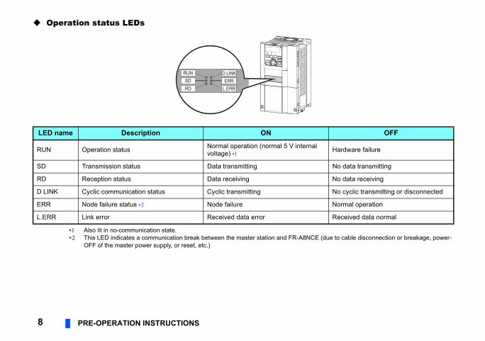
Operation status LEDs
Also lit in no-communication state. This LED indicates a communication break between the master station and FR-A8NCE
OFF of the master power supply, or reset, etc.)
LED name Description ON
RUN Operation status Normal operation (normal 5 V internal voltage)
SD Transmission status Data transmitting
RD Reception status Data receiving
D LINK Cyclic communication status Cyclic transmitting
ERR Node failure status Node failure
L.ERR Link error Received data error
SD ERRL.ERRRD
D LINKRUN
ERATION INSTRUCTIONS 9
1
pecifications
ord transmissions.)
tegory 5e) compliant shielded 4-pair
de)
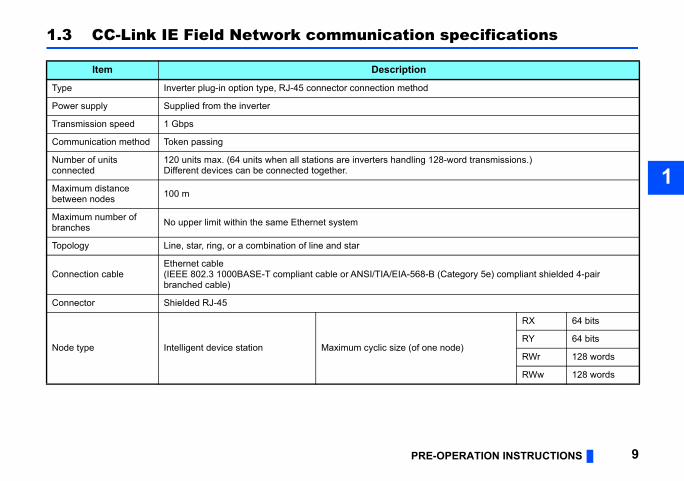
RX 64 bits
RY 64 bits
RWr 128 words
RWw 128 words
PRE-OP
1.3 CC-Link IE Field Network communication s
Item Description
Type Inverter plug-in option type, RJ-45 connector connection method
Power supply Supplied from the inverter
Transmission speed 1 Gbps
Communication method Token passing
Number of units connected
120 units max. (64 units when all stations are inverters handling 128-wDifferent devices can be connected together.
Maximum distance between nodes 100 m
Maximum number of branches No upper limit within the same Ethernet system
Topology Line, star, ring, or a combination of line and star
Connection cableEthernet cable(IEEE 802.3 1000BASE-T compliant cable or ANSI/TIA/EIA-568-B (Cabranched cable)
Connector Shielded RJ-45
Node type Intelligent device station Maximum cyclic size (of one no
age the inverter or this product.rged before you touch this product.
10 INSTALLATION
2 INSTALLATION
2.1 Pre-installation instructionsCheck that the inverter's input power and the control circuit power are both OFF.
CAUTION Do not install or remove this product while the inverter power is ON. Doing so may dam To avoid damage due to static electricity, static electricity in your body must be discha
INSTALLATION 11
2
tailed) of the inverter for instructions for
e inverter front cover.
f the front cover.
Cut off the tabs with a nipper, etc.
Cut off the tabs with a nipper, etc.
unication option LED display cover
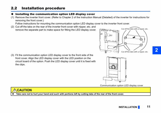
2.2 Installation procedure Installing the communication option LED display cover(1) Remove the inverter front cover. (Refer to Chapter 2 of the Instruction Manual (De
removing the front cover.)Follow instructions for mounting the communication option LED display cover to th
(2) Cut off the tabs on the rear of the inverter front cover with nipper, etc. and remove the separate part to make space for fitting the LED display cover.
(3) Fit the communication option LED display cover to the front side of the front cover. Align the LED display cover with the LED position on the circuit board of the option. Push the LED display cover until it is fixed with the clips.
CAUTION Take care not to hurt your hand and such with portions left by cutting tabs of the rear o
Comm
ries inverter, use the earthing (grounding) communication option. (For details of the
Spacer
Earth plate
Option connector on the inverter
lation to connector 1
12 INSTALLATION
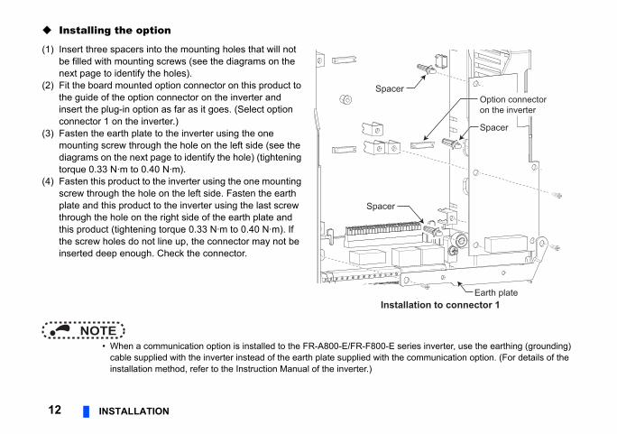
Installing the option
NOTE • When a communication option is installed to the FR-A800-E/FR-F800-E se
cable supplied with the inverter instead of the earth plate supplied with the installation method, refer to the Instruction Manual of the inverter.)
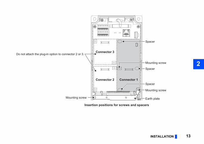
(1) Insert three spacers into the mounting holes that will not be filled with mounting screws (see the diagrams on the next page to identify the holes).
(2) Fit the board mounted option connector on this product to the guide of the option connector on the inverter and insert the plug-in option as far as it goes. (Select option connector 1 on the inverter.)
(3) Fasten the earth plate to the inverter using the one mounting screw through the hole on the left side (see the diagrams on the next page to identify the hole) (tightening torque 0.33 N·m to 0.40 N·m).
(4) Fasten this product to the inverter using the one mounting screw through the hole on the left side. Fasten the earth plate and this product to the inverter using the last screw through the hole on the right side of the earth plate and this product (tightening torque 0.33 N·m to 0.40 N·m). If the screw holes do not line up, the connector may not be inserted deep enough. Check the connector.
Spacer
Spacer
Instal
INSTALLATION 13
2Spacer
Spacer
Mounting screw
Mounting screw
Earth plate
r 1
Spacer
d spacers
Do not attach the plug-in option to connector 2 or 3.
Mounting screw
ConnectoConnector 2
Connector 3
Insertion positions for screws an
not press on the parts on the option circuit
f the plug-in option.option connector 2 or 3, the protective
nnot recognize that the option is mounted
hen pull it straight out. Pressure applied to
cur without it.
14 INSTALLATION
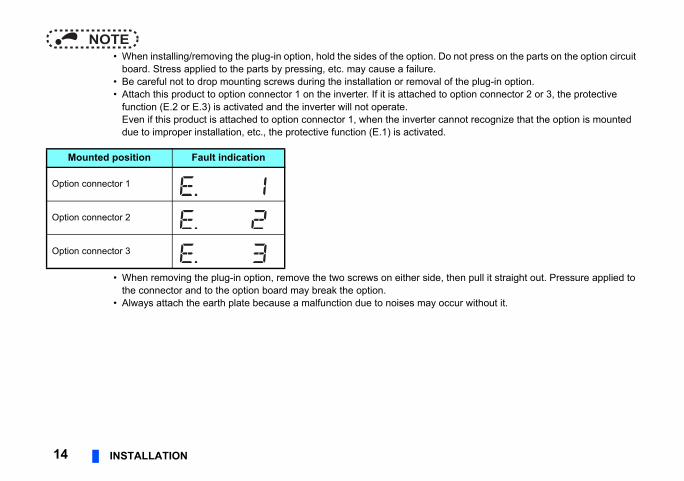
NOTE • When installing/removing the plug-in option, hold the sides of the option. Do
board. Stress applied to the parts by pressing, etc. may cause a failure. • Be careful not to drop mounting screws during the installation or removal o • Attach this product to option connector 1 on the inverter. If it is attached to
function (E.2 or E.3) is activated and the inverter will not operate.Even if this product is attached to option connector 1, when the inverter cadue to improper installation, etc., the protective function (E.1) is activated.
• When removing the plug-in option, remove the two screws on either side, tthe connector and to the option board may break the option.
• Always attach the earth plate because a malfunction due to noises may oc
Mounted position Fault indication
Option connector 1
Option connector 2
Option connector 3
WIRING 15
3
-Link IE Field Network master/local sed as the master station.
FR-A8NCE with an Ethernet cable.
rter
Motor
Inverter
MotorPowersupply
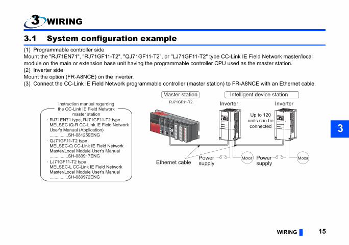
Up to 120units can beconnected
Intelligent device station
3 WIRING
3.1 System configuration example(1) Programmable controller sideMount the "RJ71EN71", "RJ71GF11-T2", "QJ71GF11-T2", or "LJ71GF11-T2" type CCmodule on the main or extension base unit having the programmable controller CPU u(2) Inverter sideMount the option (FR-A8NCE) on the inverter.(3) Connect the CC-Link IE Field Network programmable controller (master station) to
Inve
Powersupply
RJ71GF11-T2
RJ71EN71 type, RJ71GF11-T2 typeMELSEC iQ-R CC-Link IE Field Network User's Manual (Application)...............SH-081259ENG
LJ71GF11-T2 typeMELSEC-L CC-Link IE Field Network Master/Local Module User's Manual...............SH-080972ENG
Instruction manual regardingthe CC-Link IE Field Network
master station
Ethernet cable
QJ71GF11-T2 typeMELSEC-Q CC-Link IE Field Network Master/Local Module User's Manual...............SH-080917ENG
Master station
y cannot be combined with star or line
a time, all stations on the network will be
.
twork Master/Local Module User's Manual
les. Slave stations can be easily added in a stations in a star topology.
ching hub. If an error occurs, the station in
es among normallyoperating stations without
16 WIRING
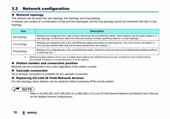
3.2 Network configuration Network topologyThe network can be wired into star topology, line topology, and ring topology.A network can consist of a combination of star and line topologies, but the ring topologtopology.
Add/remove slave stations one by one. If multiple slave stations are added/removed at reconnected, resulting in a momentarily error in all the stations.
Station number and connection positionModules can be connected in any order regardless of the station number. Cascade connectionUp to 20-layer connection is available for the cascade connection. Replacing CC-Link IE Field Network devicesFor star topology, slave stations can be replaced without powering off the whole system
NOTE • Refer to the MELSEC iQ-R, MELSEC-Q, or MELSEC-L CC-Link IE Field Ne
for the detailed network configurations.
Item Description
Star topology Modules are configured into a star using a switching hub and Ethernet cabstar topology. Furthermore, data link continues among normally-operating
Line topology Modules are configured into a line with Ethernet cables and without a switerror and the stations after that will be disconnected from the network.
Ring topology Modules are configured into a ring using Ethernet cables. Data link continua switching hub.
WIRING 17
3
ents by CC-Link Partner Association.ield Network.
Type
ing conditioning cables:2.3 (1000BASE-T)A/EIA-568-B (Category 5e)
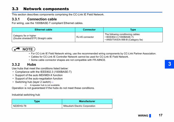
3.3 Network componentsThis section describes components comprising the CC-Link IE Field Network.
3.3.1 Connection cableFor wiring, use the 1000BASE-T compliant Ethernet cables.
NOTE • For CC-Link IE Field Network wiring, use the recommended wiring compon • Cables for CC-Link IE Controller Network cannot be used for CC-Link IE F • Some cable connector shapes are not compatible with FR-A8NCE.
3.3.2 HubsUse hubs that meet the conditions listed below: • Compliance with the IEEE802.3 (1000BASE-T) • Support of the auto MDI/MDI-X function • Support of the auto-negotiation function • Switching hub (layer 2 switch)
A repeater hub is not available.Operation is not guaranteed if the hubs do not meet these conditions.
Industrial switching hub
Ethernet cable Connector
Category 5e or higher(Double shielded/STP) Straight cable RJ-45 connector
The follow• IEEE80• ANSI/TI
Type Manufacturer
NZ2EHG-T8 Mitsubishi Electric Corporation
bles, and hubs used for the wiring, refer
18 WIRING
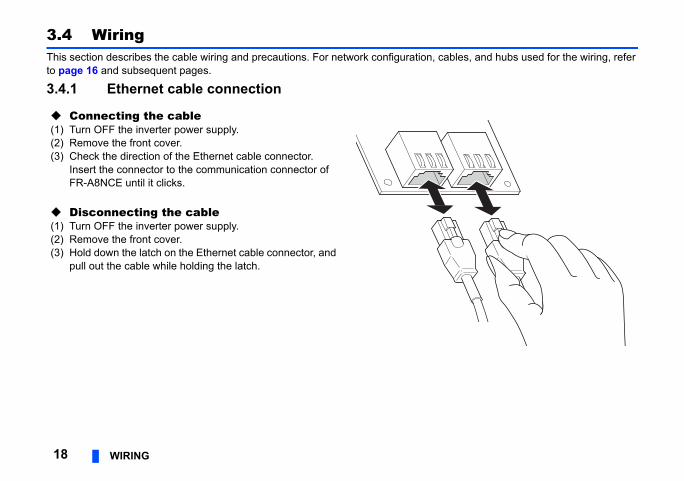
3.4 WiringThis section describes the cable wiring and precautions. For network configuration, cato page 16 and subsequent pages.
3.4.1 Ethernet cable connection
Connecting the cable(1) Turn OFF the inverter power supply.(2) Remove the front cover.(3) Check the direction of the Ethernet cable connector.
Insert the connector to the communication connector of FR-A8NCE until it clicks.
Disconnecting the cable(1) Turn OFF the inverter power supply.(2) Remove the front cover.(3) Hold down the latch on the Ethernet cable connector, and
pull out the cable while holding the latch.
WIRING 19
3
T2 is applicable.net cable can be connected to the d between PORT1s or between PORT1
tweenRT2
To the next connector for communication (PORT2)
nectoror nicationRT2)
Connectorfor
communication (PORT1)
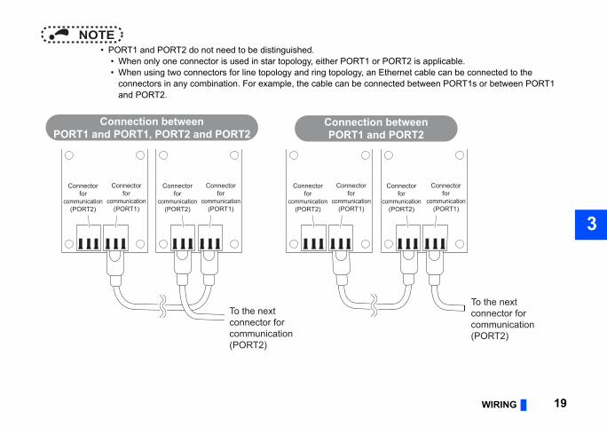
NOTE • PORT1 and PORT2 do not need to be distinguished.
• When only one connector is used in star topology, either PORT1 or POR • When using two connectors for line topology and ring topology, an Ether
connectors in any combination. For example, the cable can be connecteand PORT2.
Connection betweenPORT1 and PORT1, PORT2 and PORT2
Connection bePORT1 and PO
To the next connector for communication (PORT2)
Connectorfor
communication(PORT2)
Connectorfor
communication (PORT1)
Connectorfor
communication(PORT2)
Connectorfor
communication (PORT1)
Connectorfor
communication(PORT2)
Connectorfor
communication (PORT1)
Conf
commu(PO
dirt or dust. If oil from your hand, dirt or ata link.
lug or malfunction.
g a cable connected to the module may
rter depending on the operating
20 WIRING
3.4.2 PrecautionsThis section describes wiring precautions.
Handling of the Ethernet cable • Do not touch the core of the cable-side or module-side connector, and protect it from
dust is attached to the core, it can increase transmission loss, arising a problem in d • Check the following:
• Is any Ethernet cable disconnected? • Is any of the Ethernet cables shorted? • Are the connectors securely connected?
Broken Ethernet cable latchDo not use Ethernet cables with broken latches. Doing so may cause the cable to unp
Connecting and disconnecting the Ethernet cableHold the connector part when connecting and disconnecting the Ethernet cable. Pullindamage the module or cable, or result in malfunction due to poor contact.
Maximum station-to-station distance (maximum cable length)The maximum station-to-station distance is 100 m. However, the distance may be shoenvironment of the cable. For details, contact your cable manufacturer.
Network configurationCheck the instructions on page 16 before wiring, and perform correct wiring.
WIRING 21
3
Connecting/disconnecting a cable and powering ON/OFF a deviceconnected. At that time, a data link error cur in the connected inverters.
nication error execution waiting time
switching hubecting it to another slave station or to the
mber of slave stations in the system or more
om multiple stationscur in all the stations.)mber of slave stations in the system or more
tary errorations
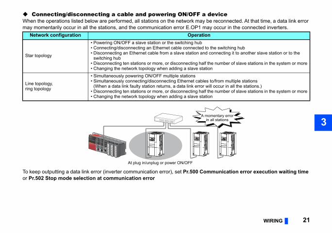
When the operations listed below are performed, all stations on the network may be remay momentarily occur in all the stations, and the communication error E.OP1 may oc
To keep outputting a data link error (inverter communication error), set Pr.500 Commuor Pr.502 Stop mode selection at communication error
Network configuration Operation
Star topology
• Powering ON/OFF a slave station or the switching hub• Connecting/disconnecting an Ethernet cable connected to the • Disconnecting an Ethernet cable from a slave station and conn
switching hub• Disconnecting ten stations or more, or disconnecting half the nu• Changing the network topology when adding a slave station
Line topology, ring topology
• Simultaneously powering ON/OFF multiple stations• Simultaneously connecting/disconnecting Ethernet cables to/fr
(When a data link faulty station returns, a data link error will oc• Disconnecting ten stations or more, or disconnecting half the nu• Changing the network topology when adding a slave station
At plug in/unplug or power ON/OFF
A momenin all st
mounted, take caution not to let the cables gnetic noises may cause malfunctions.
rm, failure or malfunction.
22 WIRING
NOTE • When wiring cables to the inverter's RS-485 terminals with a plug-in option
touch the circuit board of the option or of the inverter. Otherwise, electroma.
Caution After wiring, wire offcuts must not be left in the inverter. Wire offcuts can cause an ala

INVERTER SETTING 23
4
according to need. For the parameter anual (Detailed) of the inverter.
Minimumsetting
increments
Initialvalue
Referto
page
1 0 25
the 1 9999 56
1 0
1 0
1 0 25
1 0
1 0 34
1 0 36
1 0 36
4 INVERTER SETTING
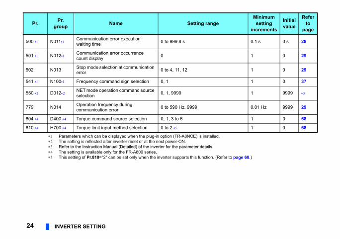
4.1 Parameter listThe following parameters are used for the plug-in option (FR-A8NCE). Set the values details, which depend on the applicable model of the inverter, refer to the Instruction M
Pr. Pr.group Name Setting range
79 D000 Operation mode selection 0 to 4, 6, 7
313 M410 DO0 output selectionThe setting range depends on inverter.314 M411 DO1 output selection
315 M412 DO2 output selection
338 D010 Communication operation command source 0, 1
339 D011 Communication speed command source 0 to 2
340 D001 Communication startup mode selection 0 to 2, 10, 12
342 N001 Communication EEPROM write selection 0, 1
349 N010 Communication reset selection 0, 1
434 , N110, Network number (CC-Link IE) 0 to 255
435 , N111, Station number (CC-Link IE) 0 to 255
er to page 68.)
0.1 s 0 s 28
1 0 29
1 0 29
1 0 37
1 9999
0.01 Hz 9999 29
1 0 68
1 0 68
Minimumsetting
increments
Initialvalue
Referto
page
24 INVERTER SETTING
Parameters which can be displayed when the plug-in option (FR-A8NCE) is installed. The setting is reflected after inverter reset or at the next power-ON. Refer to the Instruction Manual (Detailed) of the inverter for the parameter details. The setting is available only for the FR-A800 series. This setting of Pr.810="2" can be set only when the inverter supports this function. (Ref
500 N011 Communication error execution waiting time 0 to 999.8 s
501 N012 Communication error occurrence count display 0
502 N013 Stop mode selection at communication error 0 to 4, 11, 12
541 N100 Frequency command sign selection 0, 1
550 D012 NET mode operation command source selection 0, 1, 9999
779 N014 Operation frequency during communication error 0 to 590 Hz, 9999
804 D400 Torque command source selection 0, 1, 3 to 6
810 H700 Torque limit input method selection 0 to 2
Pr. Pr.group Name Setting range
INVERTER SETTING 25
4
up mode (Pr.79, Pr.340)
instantaneous power failurecan be selected.ct the network operation mode.
erter.ation mode.etting Pr.340 "0"., Pr.340.
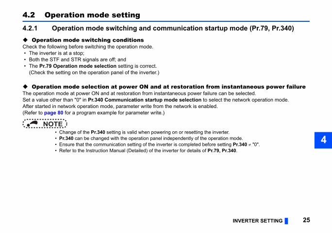
4.2 Operation mode setting
4.2.1 Operation mode switching and communication start Operation mode switching conditionsCheck the following before switching the operation mode. • The inverter is at a stop; • Both the STF and STR signals are off; and • The Pr.79 Operation mode selection setting is correct.
(Check the setting on the operation panel of the inverter.)
Operation mode selection at power ON and at restoration fromThe operation mode at power ON and at restoration from instantaneous power failure Set a value other than "0" in Pr.340 Communication startup mode selection to seleAfter started in network operation mode, parameter write from the network is enabled.(Refer to page 80 for a program example for parameter write.)
NOTE • Change of the Pr.340 setting is valid when powering on or resetting the inv • Pr.340 can be changed with the operation panel independently of the oper • Ensure that the communication setting of the inverter is completed before s • Refer to the Instruction Manual (Detailed) of the inverter for details of Pr.79
peration mode switchover
ng the External, PU, and NET operation d.,
ode fixed
een the External and Net operation mode is
e PU operation mode is disallowed.
e switching is disallowed.
ng the External, PU, and NET operation d while running.
ng the External, PU, and NET operation d.,
tion mode fixed (Forcibly switched to tion mode.)
Pr.340 = "0"
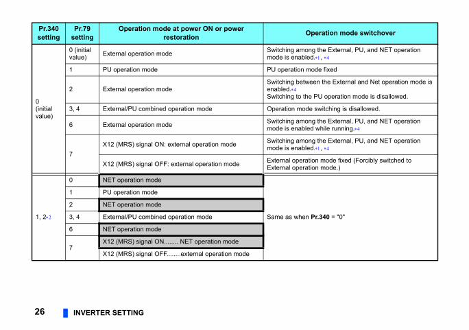
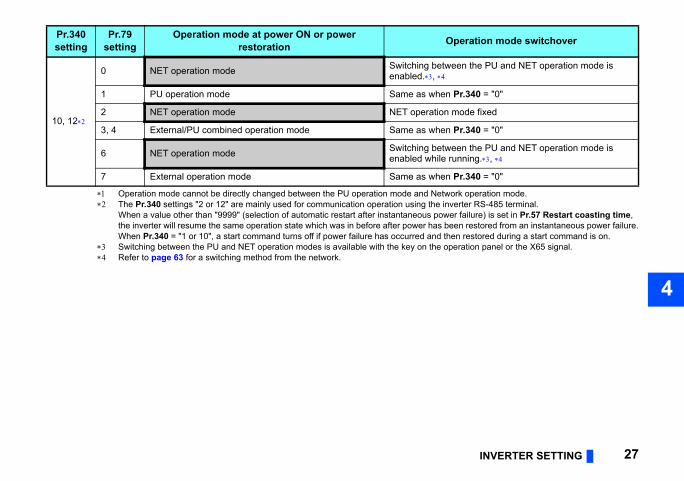
26 INVERTER SETTING
Pr.340setting
Pr.79setting
Operation mode at power ON or power restoration O
0(initial value)
0 (initial value) External operation mode Switching amo
mode is enable
1 PU operation mode PU operation m
2 External operation modeSwitching betwenabled.Switching to th
3, 4 External/PU combined operation mode Operation mod
6 External operation mode Switching amomode is enable
7X12 (MRS) signal ON: external operation mode Switching amo
mode is enable
X12 (MRS) signal OFF: external operation mode External operaExternal opera
1, 2
0 NET operation mode
Same as when
1 PU operation mode
2 NET operation mode
3, 4 External/PU combined operation mode
6 NET operation mode
7X12 (MRS) signal ON........ NET operation mode
X12 (MRS) signal OFF........external operation mode
INVERTER SETTING 27
4
ork operation mode.verter RS-485 terminal.er failure) is set in Pr.57 Restart coasting time, een restored from an instantaneous power failure.en restored during a start command is on.
peration panel or the X65 signal.
een the PU and NET operation mode is
Pr.340 = "0"
mode fixed
Pr.340 = "0"
een the PU and NET operation mode is running.,
Pr.340 = "0"
peration mode switchover
Operation mode cannot be directly changed between the PU operation mode and Netw The Pr.340 settings "2 or 12" are mainly used for communication operation using the in
When a value other than "9999" (selection of automatic restart after instantaneous powthe inverter will resume the same operation state which was in before after power has bWhen Pr.340 = "1 or 10", a start command turns off if power failure has occurred and th
Switching between the PU and NET operation modes is available with the key on the o Refer to page 63 for a switching method from the network.
10, 12
0 NET operation mode Switching betwenabled.,
1 PU operation mode Same as when
2 NET operation mode NET operation
3, 4 External/PU combined operation mode Same as when
6 NET operation mode Switching betwenabled while
7 External operation mode Same as when
Pr.340setting
Pr.79setting
Operation mode at power ON or power restoration O
ce
nce (Pr.500 to Pr.502, Pr.779).502, Pr.779 under network operation.
mmunication errorrence can be set.
is recognized as a communication error.unication error, and the operation
inimum settingincrements Initial value
s 0 s
Error
Pr.500tting time
Recognition
ON
28 INVERTER SETTING
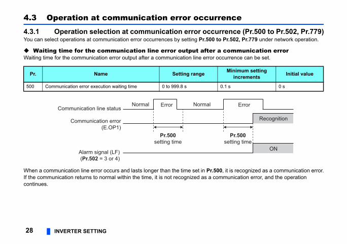
4.3 Operation at communication error occurren
4.3.1 Operation selection at communication error occurreYou can select operations at communication error occurrences by setting Pr.500 to Pr
Waiting time for the communication line error output after a coWaiting time for the communication error output after a communication line error occur
When a communication line error occurs and lasts longer than the time set in Pr.500, itIf the communication returns to normal within the time, it is not recognized as a commcontinues.
Pr. Name Setting range M
500 Communication error execution waiting time 0 to 999.8 s 0.1
Normal
se
Normal ErrorCommunication line status
Alarm signal (LF)(Pr.502 = 3 or 4)
Pr.500setting time
Communication error(E.OP1)
INVERTER SETTING 29
4
to clear this cumulative count.
urrence count display is incremented
. When the count exceeds 65535, the
rror count is stored in EEPROM only once be the one that is last stored to EEPROM
set.
inimum setting increments Initial value
0
Description
page 30.
communication error occurs, the inverter s at the set frequency.erter operates at the frequency set before munication error occurs.
Error
Incremented by 1
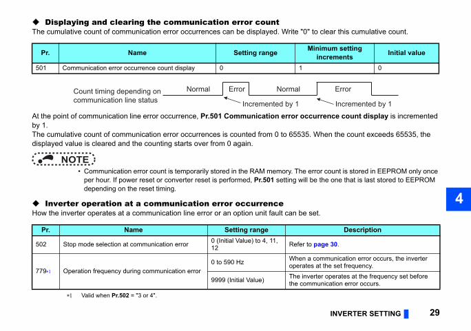
Displaying and clearing the communication error countThe cumulative count of communication error occurrences can be displayed. Write "0"
At the point of communication line error occurrence, Pr.501 Communication error occby 1.The cumulative count of communication error occurrences is counted from 0 to 65535displayed value is cleared and the counting starts over from 0 again.
NOTE • Communication error count is temporarily stored in the RAM memory. The e
per hour. If power reset or converter reset is performed, Pr.501 setting will depending on the reset timing.
Inverter operation at a communication error occurrenceHow the inverter operates at a communication line error or an option unit fault can be
Valid when Pr.502 = "3 or 4".
Pr. Name Setting range M
501 Communication error occurrence count display 0 1
Pr. Name Setting range
502 Stop mode selection at communication error 0 (Initial Value) to 4, 11, 12 Refer to
779 Operation frequency during communication error0 to 590 Hz When a
operate
9999 (Initial Value) The invthe com
Normal ErrorCount timing depending oncommunication line status Incremented by 1
Normal
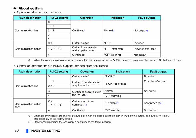
About setting
munication option error (E.OP1) does not occur.
off the output, and outputs the fault,
Fault output
Not output
Provided
Provided after stop
Not output
Fault outputProvided
Provided after stop
Not output
Kept provided
Not output
30 INVERTER SETTING
• Operation at an error occurrence
When the communication returns to normal within the time period set in Pr.500, the com
• Operation after the time in Pr.500 elapses after an error occurrence
When an error occurs, the inverter outputs a command to decelerate the motor or shutsindependently of the Pr.500 setting.
Under position control, the operation is continued to the target position.
Fault description Pr.502 setting Operation Indication
Communication line
0
Continued Normal1, 112, 1234
Communication option
0, 3 Output shutoff "E. 1"
1, 2, 11, 12 Output to decelerate and stop the motor "E. 1" after stop
4 Continued "CF" warning
Fault description Pr.502 setting Operation Indication
Communication line
0 Output shutoff "E.OP1"
1, 11 Output to decelerate and stop the motor "E.OP1" after stop
2, 12
3 Continues operation with the Pr.779.
Normal
4 "CF" warning
Communication option itself
0, 3 Output stop statuscontinues. "E.1" kept
1, 2, 11, 12
4 Continued "CF" warning
INVERTER SETTING 31
4
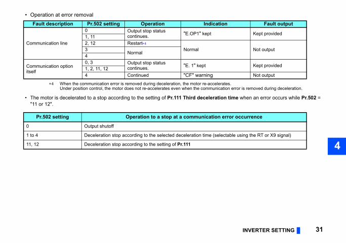
• Operation at error removal
s.n error is removed during deceleration.
time when an error occurs while Pr.502 =
Fault output
Kept provided
Not output
Kept provided
Not output
ror occurrence
ble using the RT or X9 signal)
When the communication error is removed during deceleration, the motor re-accelerateUnder position control, the motor does not re-accelerates even when the communicatio
• The motor is decelerated to a stop according to the setting of Pr.111 Third deceleration "11 or 12".
Fault description Pr.502 setting Operation Indication
Communication line
0 Output stop statuscontinues. "E.OP1" kept
1, 112, 12 Restart
Normal3Normal
4
Communication option itself
0, 3 Output stop statuscontinues. "E. 1" kept
1, 2, 11, 124 Continued "CF" warning
Pr.502 setting Operation to a stop at a communication er
0 Output shutoff
1 to 4 Deceleration stop according to the selected deceleration time (selecta
11, 12 Deceleration stop according to the setting of Pr.111
rences on the communication line. The n the communication circuit inside the
istory. (A fault record is written to the fault
fault history temporarily but not stored. back to normal, and the last fault is
.44, Pr.45, or the like) is applied as the
e.g. Pr.7, Pr.44).restart is the one given before the error
ing the error during deceleration causes r is that of the option unit itself.)
unication line error or a communication safety stop countermeasure other than S, or X92) or press the PU stop on the
32 INVERTER SETTING
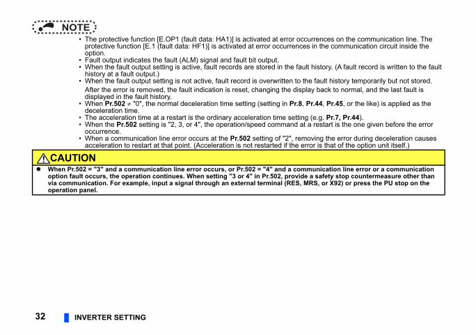
NOTE • The protective function [E.OP1 (fault data: HA1)] is activated at error occur
protective function [E.1 (fault data: HF1)] is activated at error occurrences ioption.
• Fault output indicates the fault (ALM) signal and fault bit output. • When the fault output setting is active, fault records are stored in the fault h
history at a fault output.) • When the fault output setting is not active, fault record is overwritten to the
After the error is removed, the fault indication is reset, changing the displaydisplayed in the fault history.
• When Pr.502 "0", the normal deceleration time setting (setting in Pr.8, Prdeceleration time.
• The acceleration time at a restart is the ordinary acceleration time setting ( • When the Pr.502 setting is "2, 3, or 4", the operation/speed command at a
occurrence. • When a communication line error occurs at the Pr.502 setting of "2", remov
acceleration to restart at that point. (Acceleration is not restarted if the erro
CAUTION When Pr.502 = "3" and a communication line error occurs, or Pr.502 = "4" and a comm
option fault occurs, the operation continues. When setting "3 or 4" in Pr.502, provide avia communication. For example, input a signal through an external terminal (RES, MRoperation panel.
INVERTER SETTING 33
4
s
d) of the inverter and remove the cause of the
eration modernal operation PU operationt shutoff Output shutoff
ued Continued
ued Continued
Stop
t shutoff Output shutoff
ued Continued
ued Continued
Stop
res
ove the cause of the alarm (Refer to page 8
option connector 1. option unit for poor contact, etc. and remove
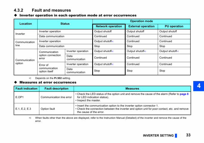
4.3.2 Fault and measures Inverter operation in each operation mode at error occurrence
Depends on the Pr.502 setting.
Measures at error occurrences
When faults other than the above are displayed, refer to the Instruction Manual (Detaileerror.
Location StatusOp
Network operation Exte
InverterInverter operation Output shutoff Outpu
Data communication Continued Contin
Communication line
Inverter operation Output shutoff Contin
Data communication Stop Stop
Communication option
Communication option connection error
Inverter operation Output shutoff Outpu
Data communication Continued Contin
Error of communication option itself
Inverter operation Output shutoff Contin
Data communication Stop Stop
Fault indication Fault description Measu
E.OP1 Communication line error• Check the LED status of the option unit and rem
for LED indication status).• Inspect the master.
E.1, E.2, E.3 Option fault• Insert the communication option to the inverter• Check the connection between the inverter and
the cause of the error.
below.
the network.twork operation mode in the initial status.ork operation mode again.
. (Refer to page 25.)trolled for about 1 s after release of a reset
Operation mode
rk on
External operation PU operation
Disallowed Disallowed
Allowed Allowed
Disallowed Disallowed
Allowed Allowed
Allowed Allowed
Allowed Allowed
Allowed Allowed
34 INVERTER SETTING
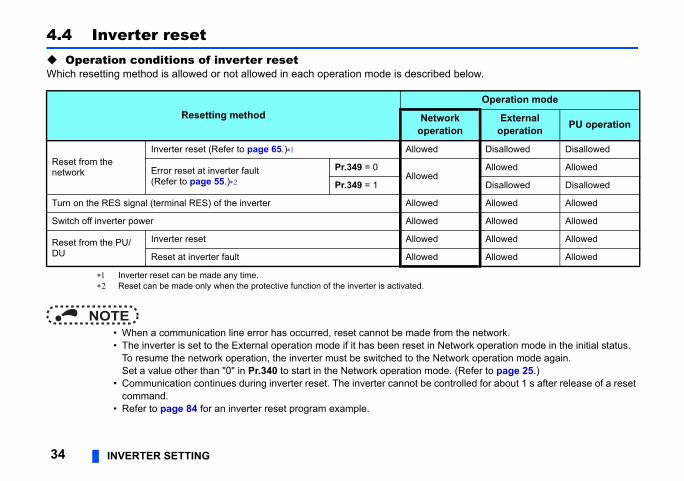
4.4 Inverter reset Operation conditions of inverter resetWhich resetting method is allowed or not allowed in each operation mode is described
Inverter reset can be made any time. Reset can be made only when the protective function of the inverter is activated.
NOTE • When a communication line error has occurred, reset cannot be made from • The inverter is set to the External operation mode if it has been reset in Ne
To resume the network operation, the inverter must be switched to the NetwSet a value other than "0" in Pr.340 to start in the Network operation mode
• Communication continues during inverter reset. The inverter cannot be concommand.
• Refer to page 84 for an inverter reset program example.
Resetting method Netwooperati
Reset from the network
Inverter reset (Refer to page 65.) Allowed
Error reset at inverter fault(Refer to page 55.)
Pr.349 = 0Allowed
Pr.349 = 1
Turn on the RES signal (terminal RES) of the inverter Allowed
Switch off inverter power Allowed
Reset from the PU/DU
Inverter reset Allowed
Reset at inverter fault Allowed
INVERTER SETTING 35
4
ration mode or PU operation mode.
Function
enabled independently of operation mode.
enabled only in the network operation mode.
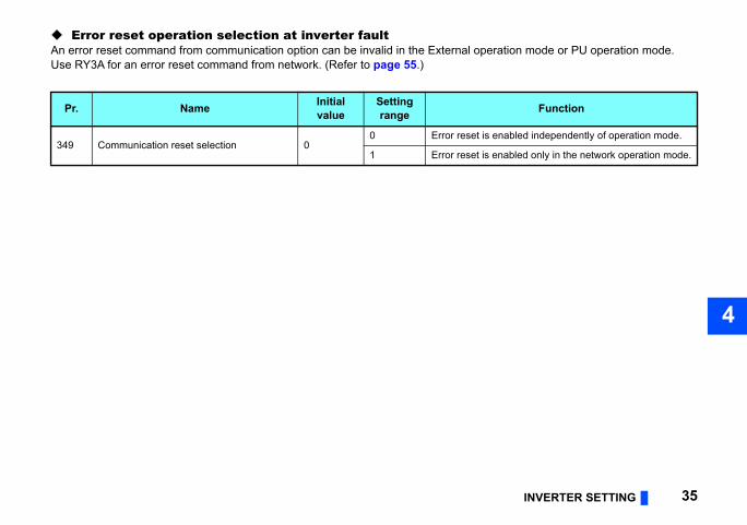
Error reset operation selection at inverter faultAn error reset command from communication option can be invalid in the External opeUse RY3A for an error reset command from network. (Refer to page 55.)
Pr. Name Initial value
Setting range
349 Communication reset selection 00 Error reset is
1 Error reset is
ed to the master station.
ed to the master station.
e the same station number, the uplicated number, re-assign the station
36 INVERTER SETTING
4.5 CC-Link IE Field Network function setting
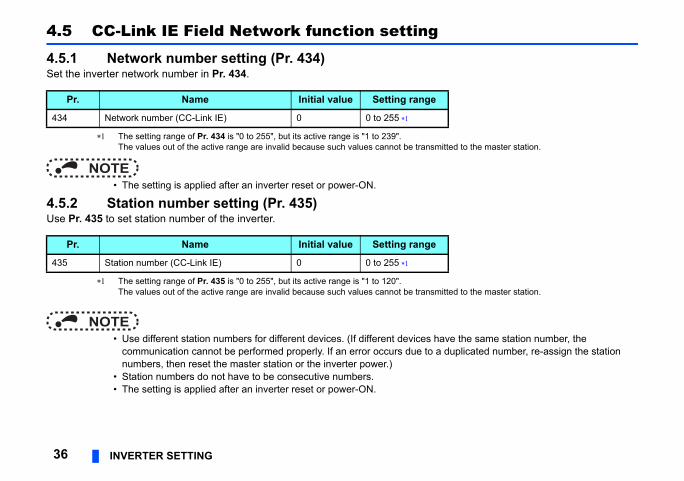
4.5.1 Network number setting (Pr. 434)Set the inverter network number in Pr. 434.
The setting range of Pr. 434 is "0 to 255", but its active range is "1 to 239". The values out of the active range are invalid because such values cannot be transmitt
NOTE • The setting is applied after an inverter reset or power-ON.
4.5.2 Station number setting (Pr. 435)Use Pr. 435 to set station number of the inverter.
The setting range of Pr. 435 is "0 to 255", but its active range is "1 to 120". The values out of the active range are invalid because such values cannot be transmitt
NOTE • Use different station numbers for different devices. (If different devices hav
communication cannot be performed properly. If an error occurs due to a dnumbers, then reset the master station or the inverter power.)
• Station numbers do not have to be consecutive numbers. • The setting is applied after an inverter reset or power-ON.
Pr. Name Initial value Setting range
434 Network number (CC-Link IE) 0 0 to 255
Pr. Name Initial value Setting range
435 Station number (CC-Link IE) 0 0 to 255
INVERTER SETTING 37
4
n be inversed to operate.
e
Actual frequency command
0 to 590.00 Hz
-327.68 to 327.67 Hz
It depends on Pr. 37, Pr. 144, Pr. 811.(in 1 or 0.1 increments)
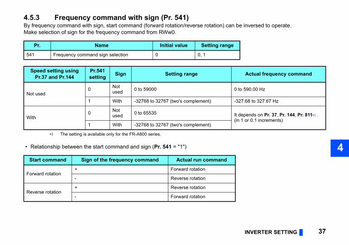
4.5.3 Frequency command with sign (Pr. 541) By frequency command with sign, start command (forward rotation/reverse rotation) caMake selection of sign for the frequency command from RWw0.
The setting is available only for the FR-A800 series.
• Relationship between the start command and sign (Pr. 541 = "1")
Pr. Name Initial value Setting rang
541 Frequency command sign selection 0 0, 1
Speed setting usingPr.37 and Pr.144
Pr.541setting Sign Setting range
Not used0 Not
used 0 to 59000
1 With -32768 to 32767 (two's complement)
With0 Not
used 0 to 65535
1 With -32768 to 32767 (two's complement)
Start command Sign of the frequency command Actual run command
Forward rotation+ Forward rotation
- Reverse rotation
Reverse rotation+ Reverse rotation
- Forward rotation
code H01) will occur.
sign bit is "positive" and the set frequency g OFF the power (inverter reset).), the sign of the frequency command is not
ents from 1 r/min to 0.1 r/min. (Only for the
38 INVERTER SETTING
NOTE • When Pr. 541 = 1 (with sign)
• When EEPROM write is specified with the RY22, write mode error (error • When both RY21 and RY22 are turned ON, RY21 has precedence. • When power is turned ON (inverter reset), the initial setting status of the
is "0 Hz". (The motor does not operate at the frequency set before turnin • When set frequency is written with the instruction code of HED and HEE
changed. • Setting "1 or 11" in Pr.811 Set resolution switchover changes the increm
FR-A800 series)
FUNCTION OVERVIEW 39
5
rkre explained below.
ollable through the network in each
Refer to page
be monitored. 56
62, 63
63
63
63
61, 64
e checked. 61
63
65
64
5 FUNCTION OVERVIEW
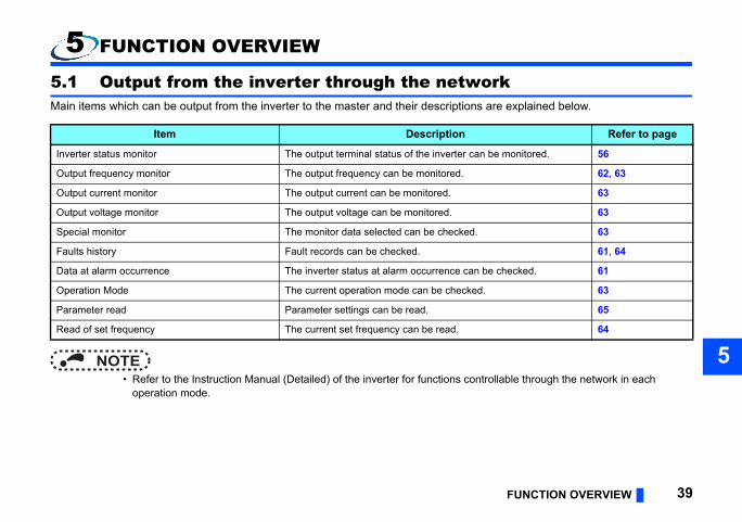
5.1 Output from the inverter through the netwoMain items which can be output from the inverter to the master and their descriptions a
NOTE • Refer to the Instruction Manual (Detailed) of the inverter for functions contr
operation mode.
Item Description
Inverter status monitor The output terminal status of the inverter can
Output frequency monitor The output frequency can be monitored.
Output current monitor The output current can be monitored.
Output voltage monitor The output voltage can be monitored.
Special monitor The monitor data selected can be checked.
Faults history Fault records can be checked.
Data at alarm occurrence The inverter status at alarm occurrence can b
Operation Mode The current operation mode can be checked.
Parameter read Parameter settings can be read.
Read of set frequency The current set frequency can be read.
ns are explained below.
ollable through the network in each
Refer to page
53
53
ut terminals. 54
54
occurs. 55
58, 64
58, 68
62, 63
63
65
l value. 65
65
65
eviation can be input 58
40 FUNCTION OVERVIEW
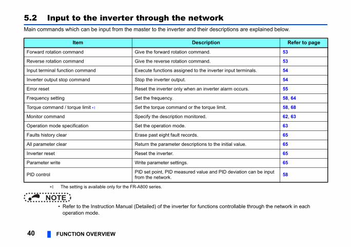
5.2 Input to the inverter through the networkMain commands which can be input from the master to the inverter and their descriptio
The setting is available only for the FR-A800 series.
NOTE • Refer to the Instruction Manual (Detailed) of the inverter for functions contr
operation mode.
Item Description
Forward rotation command Give the forward rotation command.
Reverse rotation command Give the reverse rotation command.
Input terminal function command Execute functions assigned to the inverter inp
Inverter output stop command Stop the inverter output.
Error reset Reset the inverter only when an inverter alarm
Frequency setting Set the frequency.
Torque command / torque limit Set the torque command or the torque limit.
Monitor command Specify the description monitored.
Operation mode specification Set the operation mode.
Faults history clear Erase past eight fault records.
All parameter clear Return the parameter descriptions to the initia
Inverter reset Reset the inverter.
Parameter write Write parameter settings.
PID control PID set point, PID measured value and PID dfrom the network.
FUNCTION OVERVIEW 41
5
k devices (RX, RY, RWr, and RWw) are
t to the external device of the slave stored in the link devices (RX and RWr)
5.3 Cyclic transmissionData communication is available periodically among stations on the same network. Linused.
5.3.1 Data flow and link device assignment Master and slave stations (except for local stations)One-to-one communication is possible between the master and slave stations.The status information of the link devices (RY and RWw) of the master station is outpustation, and the input status information from the external device of the slave station isof the master station.
Slave station
Station No.2
RX, RWr
RY, RWw(4)
(5)
Station No.2
for sending to r stations
Station No.2
42 FUNCTION OVERVIEW
1
Slave station
Station No.1
RX, RWr
Masterstation
StationNo.1
StationNo.2
CPUmodule
DeviceRX, RWrENDENDEND Link refresh
Link refresh
Linkscan
RY, RWw
(1)
(2)
(3)
(3)
(4)
(5)
(6)
(6)
(7)
Station No.1
RY, RWw
Sequencescan
Sequencescan
ENDENDEND
Station No.0
Areaothe
StationNo.1
StationNo.2
Station No.1
M0Y
Device
FUNCTION OVERVIEW 43
5
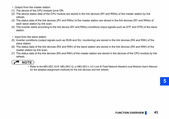
• Output from the master station
Ww) of the master station by link
in the link devices (RY and RWw) of
nals such as STF and STR) of the slave
the link devices (RX and RWr) of the
the link devices (RX and RWr) of the
n the devices of the CPU module by link
twork Master/Local Module User's Manual
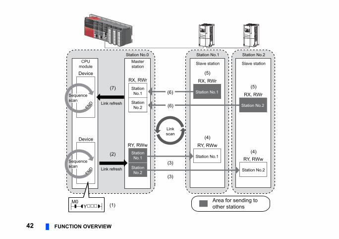
(1) The device of the CPU module turns ON.(2) The device status data of the CPU module are stored in the link devices (RY and R
refresh.(3) The status data of the link devices (RY and RWw) of the master station are stored
each slave station by link scan.(4) The inverter starts according to the link device (RY and RWw) conditions (input sig
station.
• Input from the slave station(5) Inverter conditions (output signals such as RUN and SU, monitoring) are stored in
slave station.(6) The status data of the link devices (RX and RWr) of the slave station are stored in
master station by link scan.(7) The status data of the link devices (RX and RWr) of the master station are stored i
refresh.
NOTE • Refer to the MELSEC iQ-R, MELSEC-Q, or MELSEC-L CC-Link IE Field Ne
for the detailed assignment methods for the link devices and link refresh.
SignalRefer
topage
running 56
running 56
(terminal RUN function) 56
quency SU function) 56
alarm OL function) 56
eous power failure IPF function) 56
cy detection FU function) 56
minal ABC1 function) 56
nal ABC2 function) 56
44 I/O SIGNAL LIST
6 I/O SIGNAL LIST
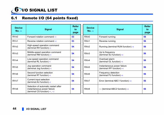
6.1 Remote I/O (64 points fixed)
DeviceNo. Signal
Referto
page
DeviceNo.
RYn0 Forward rotation command 53 RXn0 Forward
RYn1 Reverse rotation command 53 RXn1 Reverse
RYn2 High-speed operation command (terminal RH function) 54 RXn2 Running
RYn3 Middle-speed operation command (terminal RM function) 54 RXn3 Up to fre
(terminal
RYn4 Low-speed operation command (terminal RL function) 54 RXn4 Overload
(terminal
RYn5 Jog operation command (terminal Jog function) 54 RXn5 Instantan
(terminal
RYn6 Second function selection (terminal RT function) 54 RXn6 Frequen
(terminal
RYn7 Current input selection (terminal AU function) 54 RXn7 Error (ter
RYn8Selection of automatic restart after instantaneous power failure (terminal CS function) ,
54 RXn8 — (termi
I/O SIGNAL LIST 45
6
d —
ssignment function (DO0) 56
ssignment function (DO1) 56
ssignment function (DO2) 56
d —
g 57
cy setting completion (RAM) 57
cy setting completion EPROM) 57
ommand / torque limit setting on (RAM) 57
ommand / torque limit setting on (RAM, EEPROM) 57
n code execution completion 57
d —
tus flag 57
SignalRefer
topage
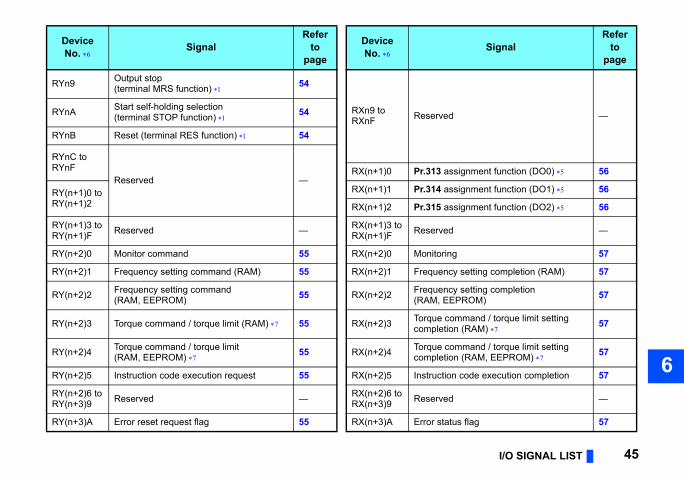
RYn9 Output stop (terminal MRS function) 54
RXn9 toRXnF ReserveRYnA Start self-holding selection
(terminal STOP function) 54
RYnB Reset (terminal RES function) 54
RYnC toRYnF
Reserved —RX(n+1)0 Pr.313 a
RY(n+1)0 toRY(n+1)2
RX(n+1)1 Pr.314 a
RX(n+1)2 Pr.315 a
RY(n+1)3 toRY(n+1)F Reserved — RX(n+1)3 to
RX(n+1)F Reserve
RY(n+2)0 Monitor command 55 RX(n+2)0 Monitorin
RY(n+2)1 Frequency setting command (RAM) 55 RX(n+2)1 Frequen
RY(n+2)2 Frequency setting command (RAM, EEPROM) 55 RX(n+2)2 Frequen
(RAM, E
RY(n+2)3 Torque command / torque limit (RAM) 55 RX(n+2)3 Torque ccompleti
RY(n+2)4 Torque command / torque limit (RAM, EEPROM) 55 RX(n+2)4 Torque c
completi
RY(n+2)5 Instruction code execution request 55 RX(n+2)5 Instructio
RY(n+2)6 toRY(n+3)9 Reserved — RX(n+2)6 to
RX(n+3)9 Reserve
RY(n+3)A Error reset request flag 55 RX(n+3)A Error sta
DeviceNo. Signal
Referto
page
DeviceNo.
ut signal functions..
tput signal functions..
minal function selection)..
station ready 57
d —
SignalRefer
topage
46 I/O SIGNAL LIST
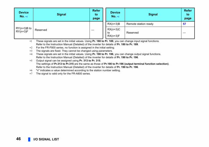
These signals are set in the initial values. Using Pr. 180 to Pr. 189, you can change inpRefer to the Instruction Manual (Detailed) of the inverter for details of Pr. 180 to Pr. 189
For the FR-F800 series, no function is assigned in the initial setting. The signals are fixed. They cannot be changed using parameters. These signals are set in the initial values. Using Pr. 190 to Pr. 196, you can change ou
Refer to the Instruction Manual (Detailed) of the inverter for details of Pr. 190 to Pr. 196 Output signal can be assigned using Pr. 313 to Pr. 315.
The settings of Pr.313 to Pr.315 are the same as those of Pr.190 to Pr.196 (output terRefer to the Instruction Manual (Detailed) of the inverter for details of Pr. 190 to Pr. 196
"n" indicates a value determined according to the station number setting. The signal is valid only for the FR-A800 series.
RY(n+3)B toRY(n+3)F Reserved —
RX(n+3)B Remote
RX(n+3)C toRX(n+3)F
Reserve
DeviceNo. Signal
Referto
page
DeviceNo.
I/O SIGNAL LIST 47
6
Description Referto
pageer 8 bits Lower 8 bits
de 60
d —
de 60
d —
de 60
de 60
de 60
d —
de 61
ta 61
de 61
ta 61
de 61
ta 61
de 61
ta 61
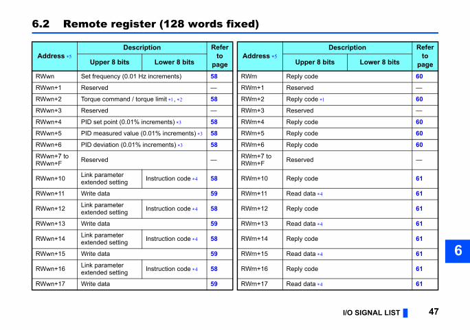
6.2 Remote register (128 words fixed)
Address Description Refer
topage
Address Upper 8 bits Lower 8 bits Upp
RWwn Set frequency (0.01 Hz increments) 58 RWrn Reply co
RWwn+1 Reserved — RWrn+1 Reserve
RWwn+2 Torque command / torque limit , 58 RWrn+2 Reply co
RWwn+3 Reserved — RWrn+3 Reserve
RWwn+4 PID set point (0.01% increments) 58 RWrn+4 Reply co
RWwn+5 PID measured value (0.01% increments) 58 RWrn+5 Reply co
RWwn+6 PID deviation (0.01% increments) 58 RWrn+6 Reply co
RWwn+7 to RWwn+F Reserved — RWrn+7 to
RWrn+F Reserve
RWwn+10 Link parameterextended setting Instruction code 58 RWrn+10 Reply co
RWwn+11 Write data 59 RWrn+11 Read da
RWwn+12 Link parameterextended setting Instruction code 58 RWrn+12 Reply co
RWwn+13 Write data 59 RWrn+13 Read da
RWwn+14 Link parameterextended setting Instruction code 58 RWrn+14 Reply co
RWwn+15 Write data 59 RWrn+15 Read da
RWwn+16 Link parameterextended setting Instruction code 58 RWrn+16 Reply co
RWwn+17 Write data 59 RWrn+17 Read da
de 61
ta 61
de 61
ta 61
d —
tus 61
istory No. Fault record(fault data) 61
ord (output frequency) 61
ord (output current) 61
ord (output voltage) 61
ord (energization time) 62
nitor value 62
monitor value 62
nitor value 62
onitor value 62
nitor value 62
nitor value 62
monitor value 62
onitor value 62
Description Referto
pageer 8 bits Lower 8 bits
48 I/O SIGNAL LIST
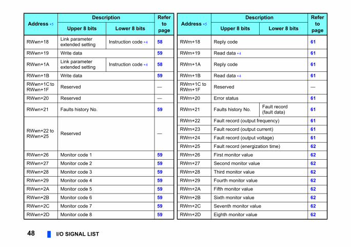
RWwn+18 Link parameterextended setting Instruction code 58 RWrn+18 Reply co
RWwn+19 Write data 59 RWrn+19 Read da
RWwn+1A Link parameterextended setting Instruction code 58 RWrn+1A Reply co
RWwn+1B Write data 59 RWrn+1B Read da
RWwn+1C to RWwn+1F Reserved — RWrn+1C to
RWrn+1F Reserve
RWwn+20 Reserved — RWrn+20 Error sta
RWwn+21 Faults history No. 59 RWrn+21 Faults h
RWwn+22 to RWwn+25 Reserved —
RWrn+22 Fault rec
RWrn+23 Fault rec
RWrn+24 Fault rec
RWrn+25 Fault rec
RWwn+26 Monitor code 1 59 RWrn+26 First mo
RWwn+27 Monitor code 2 59 RWrn+27 Second
RWwn+28 Monitor code 3 59 RWrn+28 Third mo
RWwn+29 Monitor code 4 59 RWrn+29 Fourth m
RWwn+2A Monitor code 5 59 RWrn+2A Fifth mo
RWwn+2B Monitor code 6 59 RWrn+2B Sixth mo
RWwn+2C Monitor code 7 59 RWrn+2C Seventh
RWwn+2D Monitor code 8 59 RWrn+2D Eighth m
Address Description Refer
topage
Address Upper 8 bits Lower 8 bits Upp
I/O SIGNAL LIST 49
6
onitor value 62
onitor value 62
requency 62
d —
urrent 62
oltage 62
d —
cy setting value 62
speed 62
rque 62
er output voltage 62
rative brake duty 62
thermal relay function load factor 62
urrent peak value 62
er output voltage peak value 62
wer 62
ower 62
minal status 62
erminal status 62
Description Referto
pageer 8 bits Lower 8 bits
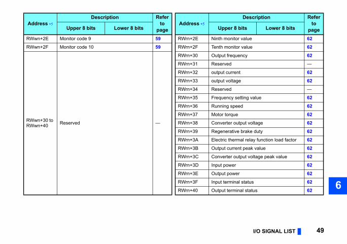
RWwn+2E Monitor code 9 59 RWrn+2E Ninth m
RWwn+2F Monitor code 10 59 RWrn+2F Tenth m
RWwn+30 to RWwn+40 Reserved —
RWrn+30 Output f
RWrn+31 Reserve
RWrn+32 output c
RWrn+33 output v
RWrn+34 Reserve
RWrn+35 Frequen
RWrn+36 Running
RWrn+37 Motor to
RWrn+38 Convert
RWrn+39 Regene
RWrn+3A Electric
RWrn+3B Output c
RWrn+3C Convert
RWrn+3D Input po
RWrn+3E Output p
RWrn+3F Input ter
RWrn+40 Output t
Address Description Refer
topage
Address Upper 8 bits Lower 8 bits Upp
ter 62
citation current 62
pulse 62
tive energization time 62
d —
ion status 62
peration time 62
ad factor 62
tive power 62
command (lower digits) 62
command (upper digits) 62
position (lower digits) 62
position (upper digits) 62
ulse (lower digits) 62
ulse (upper digits) 62
ommand 62
urrent command 62
tput 62
k pulse 62
Description Referto
pageer 8 bits Lower 8 bits
50 I/O SIGNAL LIST
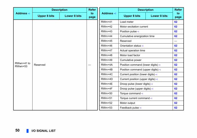
RWwn+41 to RWwn+53 Reserved —
RWrn+41 Load me
RWrn+42 Motor ex
RWrn+43 Position
RWrn+44 Cumula
RWrn+45 Reserve
RWrn+46 Orientat
RWrn+47 Actual o
RWrn+48 Motor lo
RWrn+49 Cumula
RWrn+4A Position
RWrn+4B Position
RWrn+4C Current
RWrn+4D Current
RWrn+4E Droop p
RWrn+4F Droop p
RWrn+50 Torque c
RWrn+51 Torque c
RWrn+52 Motor ou
RWrn+53 Feedbac
Address Description Refer
topage
Address Upper 8 bits Lower 8 bits Upp
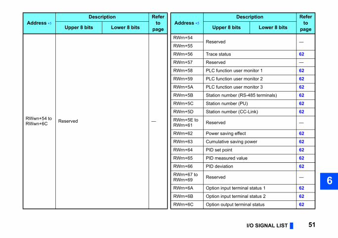
I/O SIGNAL LIST 51
6
d —
atus 62
d —
ction user monitor 1 62
ction user monitor 2 62
ction user monitor 3 62
umber (RS-485 terminals) 62
umber (PU) 62
umber (CC-Link) 62
d —
aving effect 62
tive saving power 62
point 62
sured value 62
iation 62
d —
nput terminal status 1 62
nput terminal status 2 62
utput terminal status 62
Description Referto
pageer 8 bits Lower 8 bits
RWwn+54 to RWwn+6C Reserved —
RWrn+54Reserve
RWrn+55
RWrn+56 Trace st
RWrn+57 Reserve
RWrn+58 PLC fun
RWrn+59 PLC fun
RWrn+5A PLC fun
RWrn+5B Station n
RWrn+5C Station n
RWrn+5D Station n
RWrn+5E to RWrn+61 Reserve
RWrn+62 Power s
RWrn+63 Cumula
RWrn+64 PID set
RWrn+65 PID mea
RWrn+66 PID dev
RWrn+67 to RWrn+69 Reserve
RWrn+6A Option i
RWrn+6B Option i
RWrn+6C Option o
Address Description Refer
topage
Address Upper 8 bits Lower 8 bits Upp
e 68.)
instruction may differ at different timings if other
ermal load factor 62
thermal load factor 62
d —
rmistor value 62
d —
sured value 2 62
ncy drive status 62
d —
tive pulse 62
tive pulse carrying-over times 62
tive pulse (control terminal option) 62
tive pulse carrying-over times terminal option) 62
d —
Description Referto
pageer 8 bits Lower 8 bits
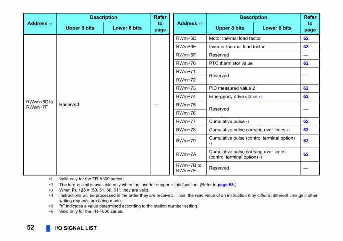
52 I/O SIGNAL LIST
Valid only for the FR-A800 series. The torque limit is available only when the inverter supports this function. (Refer to pag When Pr. 128 = "50, 51, 60, 61", they are valid. Instructions will be processed in the order they are received. Thus, the read value of an
writing requests are being made. "n" indicates a value determined according to the station number setting. Valid only for the FR-F800 series.
RWwn+6D to RWwn+7F Reserved —
RWrn+6D Motor th
RWrn+6E Inverter
RWrn+6F Reserve
RWrn+70 PTC the
RWrn+71Reserve
RWrn+72
RWrn+73 PID mea
RWrn+74 Emerge
RWrn+75Reserve
RWrn+76
RWrn+77 Cumula
RWrn+78 Cumula
RWrn+79 Cumula
RWrn+7A Cumula(control
RWrn+7B to RWrn+7F Reserve
Address Description Refer
topage
Address Upper 8 bits Lower 8 bits Upp
DETAILS OF I/O SIGNALS 53
7
ual for correspondence between the
E))
Description
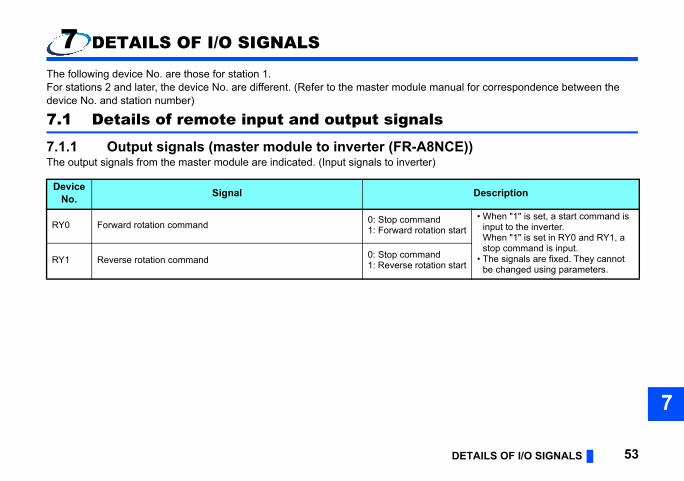
start• When "1" is set, a start command is
input to the inverter.When "1" is set in RY0 and RY1, a stop command is input.
• The signals are fixed. They cannot be changed using parameters.start
7 DETAILS OF I/O SIGNALS
The following device No. are those for station 1.For stations 2 and later, the device No. are different. (Refer to the master module mandevice No. and station number)
7.1 Details of remote input and output signals
7.1.1 Output signals (master module to inverter (FR-A8NCThe output signals from the master module are indicated. (Input signals to inverter)
DeviceNo. Signal
RY0 Forward rotation command 0: Stop command1: Forward rotation
RY1 Reverse rotation command 0: Stop command1: Reverse rotation
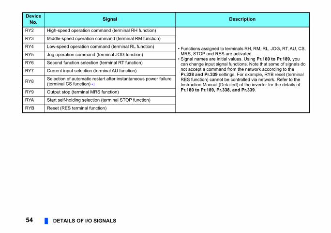
to terminals RH, RM, RL, JOG, RT, AU, CS, ES are activated.nitial values. Using Pr.180 to Pr.189, you ignal functions. Note that some of signals do and from the network according to the settings. For example, RYB reset (terminal ot be controlled via network. Refer to the
(Detailed) of the inverter for the details of r.338, and Pr.339.
Description
54 DETAILS OF I/O SIGNALS
RY2 High-speed operation command (terminal RH function)
• Functions assignedMRS, STOP and R
• Signal names are ican change input snot accept a commPr.338 and Pr.339RES function) cannInstruction ManualPr.180 to Pr.189, P
RY3 Middle-speed operation command (terminal RM function)
RY4 Low-speed operation command (terminal RL function)
RY5 Jog operation command (terminal JOG function)
RY6 Second function selection (terminal RT function)
RY7 Current input selection (terminal AU function)
RY8 Selection of automatic restart after instantaneous power failure (terminal CS function)
RY9 Output stop (terminal MRS function)
RYA Start self-holding selection (terminal STOP function)
RYB Reset (RES terminal function)
DeviceNo. Signal
DETAILS OF I/O SIGNALS 55
7
alue is set in the remote register RWr26 to the monitor command (RY20), the
t frequency (RWw0) is written to RAM of the plied.
pletion (RX21).t frequency (RWw0) is written to RAM and
the frequency setting completion (RX22).y to the inverter RAM.set torque command / torque limit (RWw2) is
rque limit setting completion (RX23).
set torque command / torque limit (RWw2) is
rque limit setting completion (RX24).
, be sure to write data to the inverter RAM., processes corresponding to the instruction set in the instruction code execution request n code execution error occurs, a value other
er fault, the inverter is reset, then "0" is set in itions of inverter reset.
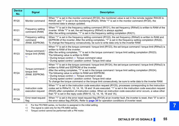
For the FR-F800 series, no function is assigned in the initial setting. The signal is valid only for the FR-A800 series. Torque control cannot be performed with a PM motor.
DeviceNo. Signal Description
RY20 Monitor commandWhen "1" is set in the monitor command (RY20), the monitored vRWr2F, and "1" is set in the monitoring (RX20). While "1" is set inmonitored data is always updated.
RY21 Frequency setting command (RAM)
When "1" is set in the frequency setting command (RY21), the seinverter. While "1" is set, the set frequency (RWw0) is always apAfter the writing completes, "1" is set in the frequency setting com
RY22Frequency setting command (RAM, EEPROM)
When "1" is set in the frequency setting command (RY22), the seEEPROM of the inverter. After the writing completes, "1" is set inTo change the frequency consecutively, be sure to write data onl
RY23Torque command / torque limit (RAM)
When "1" is set in the torque command / torque limit (RY23), the written to RAM of the inverter.After the writing completes, "1" is set in the torque command / toThe following value is written to RAM.• During torque control : Torque command value• During speed control / position control: Torque limit value
RY24
Torque command / torque limit (RAM, EEPROM)
When "1" is set in the torque command / torque limit (RY24), the written to RAM and EEPROM of the inverter.After the writing completes, "1" is set in the torque command / toThe following value is written to RAM and EEPROM.• During torque control : Torque command value• During speed control / position control: Torque limit valueTo change the torque command or the torque limit consecutively
RY25 Instruction code execution request
When "1" is set in the instruction code execution request (RY25)codes set to RWw10, 12, 14, 16, 18 and 1A are executed. "1" is (RX25) after completion of instruction codes. When an instructiothan "0" is set in the reply code (RWr10, 12, 14, 16, 18 and 1A).
RY3A Error reset request flag
When "1" is set in the error reset request flag (RY3A) at an invertthe error status flag (RX3A). Refer to page 34 for operation cond
e)
escription
ing stop or reverse rotation)
ing stop or forward rotation)
UN, SU, OL, IPF, FU, ABC1 and ABC2
sing Pr.190 to Pr.196, you can change he Instruction Manual (Detailed) of the .196.
r.315 are activated. setting. Use Pr.313 to Pr.315 to assign 12. The settings of Pr.313 to Pr.315 are the
6 (output terminal function selection). etailed) of the inverter for details of Pr.190 to
56 DETAILS OF I/O SIGNALS
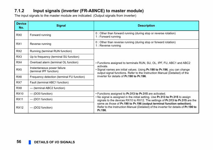
7.1.2 Input signals (inverter (FR-A8NCE) to master modulThe input signals to the master module are indicated. (Output signals from inverter)
DeviceNo. Signal D
RX0 Forward running 0 : Other than forward running (dur1 : Forward running
RX1 Reverse running 0 : Other than reverse running (dur1 : Reverse running
RX2 Running (terminal RUN function)
• Functions assigned to terminals Ractivate.
• Signal names are initial values. Uoutput signal functions. Refer to tinverter for details of Pr.190 to Pr
RX3 Up to frequency (terminal SU function)
RX4 Overload alarm (terminal OL function)
RX5 Instantaneous power failure (terminal IPF function)
RX6 Frequency detection (terminal FU function)
RX7 Fault (terminal ABC1 function)
RX8 — (terminal ABC2 function)
RX10 — (DO0 function) • Functions assigned to Pr.313 to P• No signal is assigned in the initial
signals to the devices RX10 to RXsame as those of Pr.190 to Pr.19Refer to the Instruction Manual (DPr.196.
RX11 — (DO1 function)
RX12 — (DO2 function)
DETAILS OF I/O SIGNALS 57
7
and (RY20), and the monitored value is set r2F, "1" is set in this signal. When "0" is set " is set in this signal.
ting command (RY21) and the set frequency set in this signal. When "0" is set in the
), "0" is set in this signal.
ting command (RY22) and the set frequency EPROM, "1" is set in this signal. When "0" is nd (RY22), "0" is set in this signal.
nd / torque limit (RY23) and the torque tten to the inverter RAM, "1" is set in this command / torque limit (RY23), "0" is set in
nd / torque limit (RY24) and the torque ten to the inverter RAM and EEPROM, "1" is the torque command / torque limit (RY24),
e execution request (RY25) and the truction codes (RWw10, 12, 14, 16, 18 and ignal. When "0" is set in the instruction code t in this signal.
tective function is activated), "1" is set in this
dy status upon completion of initial setting "1" is set in this signal. When an inverter activated), "0" is set in this signal.ignal during the write to/read from the master
escription
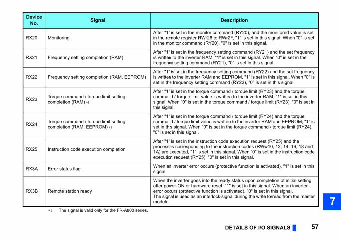
The signal is valid only for the FR-A800 series.
RX20 MonitoringAfter "1" is set in the monitor commin the remote register RWr26 to RWin the monitor command (RY20), "0
RX21 Frequency setting completion (RAM)After "1" is set in the frequency setis written to the inverter RAM, "1" isfrequency setting command (RY21
RX22 Frequency setting completion (RAM, EEPROM)After "1" is set in the frequency setis written to the inverter RAM and Eset in the frequency setting comma
RX23 Torque command / torque limit setting completion (RAM)
After "1" is set in the torque commacommand / torque limit value is wrisignal. When "0" is set in the torquethis signal.
RX24 Torque command / torque limit setting completion (RAM, EEPROM)
After "1" is set in the torque commacommand / torque limit value is writset in this signal. When "0" is set in"0" is set in this signal.
RX25 Instruction code execution completion
After "1" is set in the instruction codprocesses corresponding to the ins1A) are executed, "1" is set in this sexecution request (RY25), "0" is se
RX3A Error status flag When an inverter error occurs (prosignal.
RX3B Remote station ready
When the inverter goes into the reaafter power-ON or hardware reset,error occurs (protective function is The signal is used as an interlock smodule.
DeviceNo. Signal D
CE))
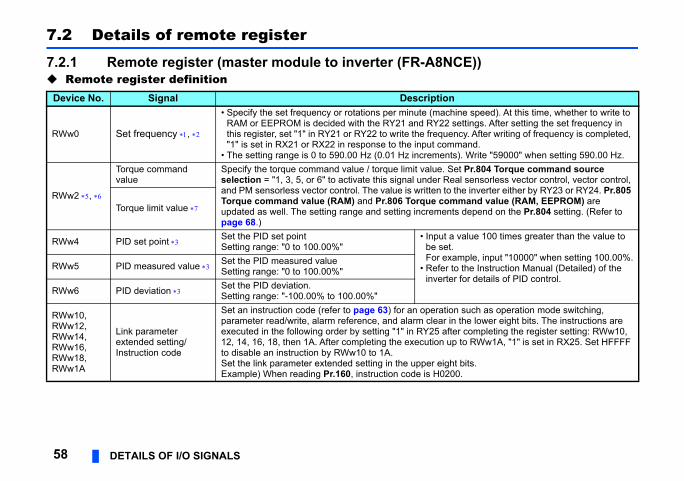
nhine speed). At this time, whether to write to settings. After setting the set frequency in ncy. After writing of frequency is completed, mand.
ts). Write "59000" when setting 590.00 Hz.et Pr.804 Torque command source
eal sensorless vector control, vector control, the inverter either by RY23 or RY24. Pr.805 mmand value (RAM, EEPROM) are ts depend on the Pr.804 setting. (Refer to
a value 100 times greater than the value to t.ample, input "10000" when setting 100.00%.
to the Instruction Manual (Detailed) of the er for details of PID control.
on such as operation mode switching, in the lower eight bits. The instructions are ter completing the register setting: RWw10, p to RWw1A, "1" is set in RX25. Set HFFFF
ht bits.00.
58 DETAILS OF I/O SIGNALS
7.2 Details of remote register
7.2.1 Remote register (master module to inverter (FR-A8N Remote register definition
Device No. Signal Descriptio
RWw0 Set frequency ,
• Specify the set frequency or rotations per minute (macRAM or EEPROM is decided with the RY21 and RY22this register, set "1" in RY21 or RY22 to write the freque"1" is set in RX21 or RX22 in response to the input com
• The setting range is 0 to 590.00 Hz (0.01 Hz incremen
RWw2 ,
Torque command value
Specify the torque command value / torque limit value. Sselection = "1, 3, 5, or 6" to activate this signal under Rand PM sensorless vector control. The value is written toTorque command value (RAM) and Pr.806 Torque coupdated as well. The setting range and setting incremenpage 68.)
Torque limit value
RWw4 PID set point Set the PID set pointSetting range: "0 to 100.00%"
• Input be seFor ex
• Referinvert
RWw5 PID measured value Set the PID measured valueSetting range: "0 to 100.00%"
RWw6 PID deviation Set the PID deviation.Setting range: "-100.00% to 100.00%"
RWw10, RWw12, RWw14, RWw16, RWw18, RWw1A
Link parameter extended setting/ Instruction code
Set an instruction code (refer to page 63) for an operatiparameter read/write, alarm reference, and alarm clear executed in the following order by setting "1" in RY25 af12, 14, 16, 18, then 1A. After completing the execution uto disable an instruction by RWw10 to 1A.Set the link parameter extended setting in the upper eigExample) When reading Pr.160, instruction code is H02
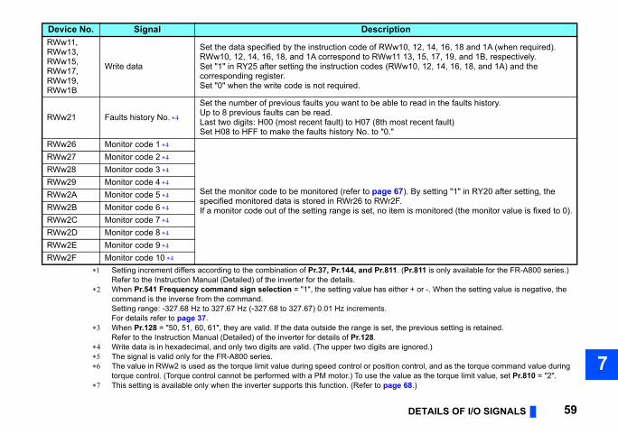
DETAILS OF I/O SIGNALS 59
7
, 12, 14, 16, 18 and 1A (when required).3, 15, 17, 19, and 1B, respectively.10, 12, 14, 16, 18, and 1A) and the
read in the faults history.
t recent fault)
. By setting "1" in RY20 after setting, the
is monitored (the monitor value is fixed to 0).
r.811 is only available for the FR-A800 series.)
r + or -. When the setting value is negative, the
previous setting is retained.
nored.)
ontrol, and as the torque command value during e as the torque limit value, set Pr.810 = "2".8.)
n
RWw11, RWw13, RWw15, RWw17, RWw19, RWw1BWrite data
Set the data specified by the instruction code of RWw10RWw10, 12, 14, 16, 18, and 1A correspond to RWw11 1Set "1" in RY25 after setting the instruction codes (RWwcorresponding register.Set "0" when the write code is not required.
RWw21 Faults history No.
Set the number of previous faults you want to be able toUp to 8 previous faults can be read.Last two digits: H00 (most recent fault) to H07 (8th mosSet H08 to HFF to make the faults history No. to "0."
RWw26 Monitor code 1
Set the monitor code to be monitored (refer to page 67)specified monitored data is stored in RWr26 to RWr2F.If a monitor code out of the setting range is set, no item
RWw27 Monitor code 2 RWw28 Monitor code 3 RWw29 Monitor code 4 RWw2A Monitor code 5 RWw2B Monitor code 6 RWw2C Monitor code 7 RWw2D Monitor code 8 RWw2E Monitor code 9 RWw2F Monitor code 10
Setting increment differs according to the combination of Pr.37, Pr.144, and Pr.811. (PRefer to the Instruction Manual (Detailed) of the inverter for the details.
When Pr.541 Frequency command sign selection = "1", the setting value has eithecommand is the inverse from the command.Setting range: -327.68 Hz to 327.67 Hz (-327.68 to 327.67) 0.01 Hz increments.For details refer to page 37.
When Pr.128 = "50, 51, 60, 61", they are valid. If the data outside the range is set, theRefer to the Instruction Manual (Detailed) of the inverter for details of Pr.128.
Write data is in hexadecimal, and only two digits are valid. (The upper two digits are ig The signal is valid only for the FR-A800 series. The value in RWw2 is used as the torque limit value during speed control or position c
torque control. (Torque control cannot be performed with a PM motor.) To use the valu This setting is available only when the inverter supports this function. (Refer to page 6
Device No. Signal Descriptio
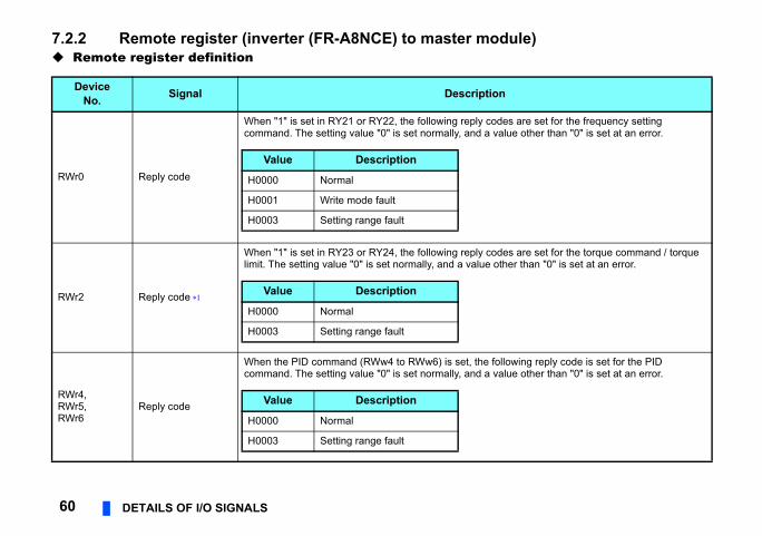
ule)
es are set for the frequency setting lue other than "0" is set at an error.
es are set for the torque command / torque her than "0" is set at an error.
llowing reply code is set for the PID lue other than "0" is set at an error.
60 DETAILS OF I/O SIGNALS
7.2.2 Remote register (inverter (FR-A8NCE) to master mod Remote register definition
DeviceNo. Signal Description
RWr0 Reply code
When "1" is set in RY21 or RY22, the following reply codcommand. The setting value "0" is set normally, and a va
RWr2 Reply code
When "1" is set in RY23 or RY24, the following reply codlimit. The setting value "0" is set normally, and a value ot
RWr4,RWr5,RWr6
Reply code
When the PID command (RWw4 to RWw6) is set, the focommand. The setting value "0" is set normally, and a va
Value Description
H0000 Normal
H0001 Write mode fault
H0003 Setting range fault
Value Description
H0000 Normal
H0003 Setting range fault
Value Description
H0000 Normal
H0003 Setting range fault
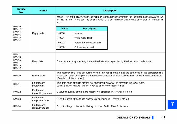
DETAILS OF I/O SIGNALS 61
7
ponding to the instruction code RWw10, 12, rmally, and a value other than "0" is set at an
fied by the instruction code is set.
ion, and the data code of the corresponding ault records, refer to the Instruction Manual
is stored in the lower 8bits.r 8 bits.
w21 is stored.
21 is stored.
21 is stored.
RWr10, RWr12, RWr14, RWr16, RWr18, RWr1A
Reply code
When "1" is set in RY25, the following reply codes corres14, 16, 18, and 1A are set. The setting value "0" is set noerror.
RWr11, RWr13, RWr15, RWr17, RWr19, RWr1B
Read data For a normal reply, the reply data to the instruction speci
RWr20 Error statusThe setting value "0" is set during normal inverter operaterror is set at an error. (For the data codes or details of f(Detailed) of the inverter.)
RWr21 Fault record(fault data)
The data code of faults history No. specified by RWw21 Lower 8 bits of RWw21 will be reverted back to the uppe
RWr22 Fault record(output frequency) Output frequency of the faults history No. specified in RW
RWr23 Fault record(output current) Output current of the faults history No. specified in RWw
RWr24 Fault record(output voltage) Output voltage of the faults history No. specified in RWw
DeviceNo. Signal Description
Value Description
H0000 Normal
H0001 Write mode fault
H0002 Parameter selection fault
H0003 Setting range fault
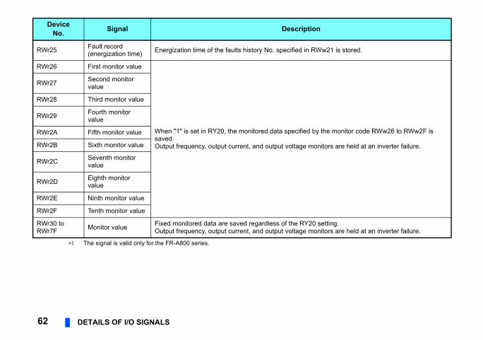
w21 is stored.
the monitor code RWw26 to RWw2F is
nitors are held at an inverter failure.
setting.nitors are held at an inverter failure.
62 DETAILS OF I/O SIGNALS
The signal is valid only for the FR-A800 series.
RWr25 Fault record (energization time) Energization time of the faults history No. specified in RW
RWr26 First monitor value
When "1" is set in RY20, the monitored data specified bysaved.Output frequency, output current, and output voltage mo
RWr27 Second monitor value
RWr28 Third monitor value
RWr29 Fourth monitor value
RWr2A Fifth monitor value
RWr2B Sixth monitor value
RWr2C Seventh monitor value
RWr2D Eighth monitor value
RWr2E Ninth monitor value
RWr2F Tenth monitor value
RWr30 to RWr7F Monitor value Fixed monitored data are saved regardless of the RY20
Output frequency, output current, and output voltage mo
DeviceNo. Signal Description
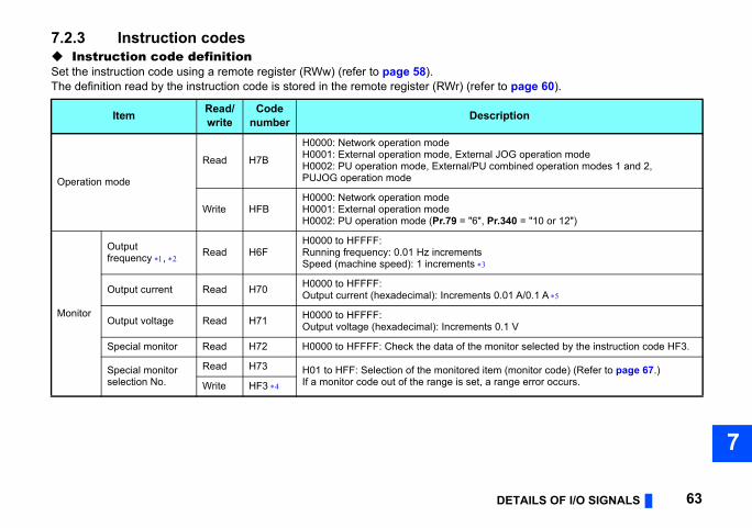
DETAILS OF I/O SIGNALS 63
7
to page 60).
ription
JOG operation modeombined operation modes 1 and 2,
r.340 = "10 or 12")
0.01 A/0.1 A
0.1 V
onitor selected by the instruction code HF3.
m (monitor code) (Refer to page 67.)range error occurs.
7.2.3 Instruction codes Instruction code definitionSet the instruction code using a remote register (RWw) (refer to page 58).The definition read by the instruction code is stored in the remote register (RWr) (refer
Item Read/write
Codenumber Desc
Operation mode
Read H7B
H0000: Network operation modeH0001: External operation mode, External H0002: PU operation mode, External/PU cPUJOG operation mode
Write HFBH0000: Network operation modeH0001: External operation modeH0002: PU operation mode (Pr.79 = "6", P
Monitor
Output frequency , Read H6F
H0000 to HFFFF:Running frequency: 0.01 Hz incrementsSpeed (machine speed): 1 increments
Output current Read H70 H0000 to HFFFF:Output current (hexadecimal): Increments
Output voltage Read H71 H0000 to HFFFF:Output voltage (hexadecimal): Increments
Special monitor Read H72 H0000 to HFFFF: Check the data of the m
Special monitorselection No.
Read H73 H01 to HFF: Selection of the monitored iteIf a monitor code out of the range is set, a Write HF3
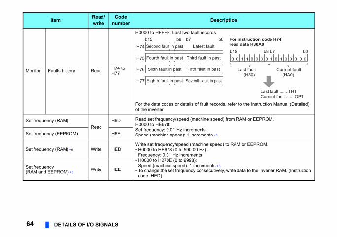
s, refer to the Instruction Manual (Detailed)
) from RAM or EEPROM.
) to RAM or EEPROM.
y, write data to the inverter RAM. (Instruction
ription
0 For instruction code H74, read data H30A0
Last fault ...... THTCurrent fault ...... OPT
0 10 1 0 0 0 0 0 0 00001 1
b15 b8 b7 b0
Current fault(HA0)
Last fault(H30)
64 DETAILS OF I/O SIGNALS
Monitor Faults history Read H74 to H77
H0000 to HFFFF: Last two fault records
For the data codes or details of fault recordof the inverter.
Set frequency (RAM)Read
H6D Read set frequency/speed (machine speedH0000 to HE678:Set frequency: 0.01 Hz incrementsSpeed (machine speed): 1 increments Set frequency (EEPROM) H6E
Set frequency (RAM) Write HEDWrite set frequency/speed (machine speed• H0000 to HE678 (0 to 590.00 Hz):
Frequency: 0.01 Hz increments• H0000 to H270E (0 to 9998):
Speed (machine speed): 1 increments • To change the set frequency consecutivel
code: HED)
Set frequency(RAM and EEPROM) Write HEE
Item Read/write
Codenumber Desc
b15 b8 b7 bLatest faultSecond fault in past
Third fault in pastFourth fault in past
Fifth fault in pastSixth fault in past
Seventh fault in pastEighth fault in past
H74
H75
H76
H77
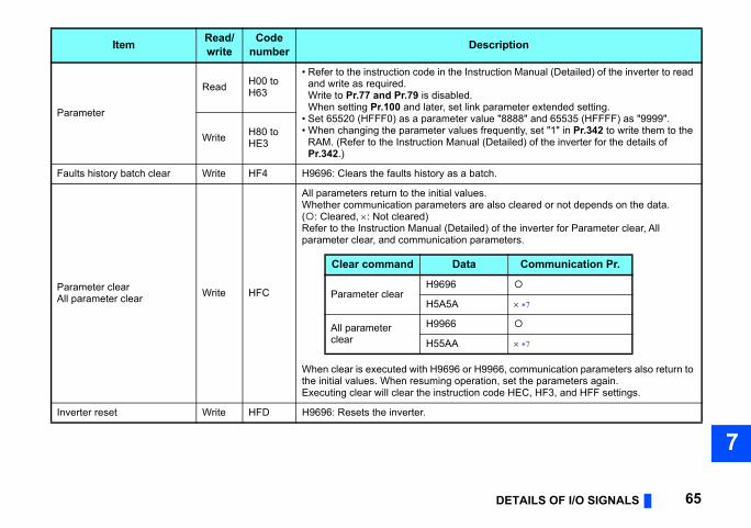
DETAILS OF I/O SIGNALS 65
7
tion Manual (Detailed) of the inverter to read
rameter extended setting. "8888" and 65535 (HFFFF) as "9999".quently, set "1" in Pr.342 to write them to the etailed) of the inverter for the details of
.
lso cleared or not depends on the data.
f the inverter for Parameter clear, All eters.
66, communication parameters also return to , set the parameters again.
de HEC, HF3, and HFF settings.
ription
Communication Pr.
Parameter
Read H00 to H63
• Refer to the instruction code in the Instrucand write as required.Write to Pr.77 and Pr.79 is disabled.When setting Pr.100 and later, set link pa
• Set 65520 (HFFF0) as a parameter value• When changing the parameter values fre
RAM. (Refer to the Instruction Manual (DPr.342.)
Write H80 to HE3
Faults history batch clear Write HF4 H9696: Clears the faults history as a batch
Parameter clearAll parameter clear Write HFC
All parameters return to the initial values.Whether communication parameters are a(: Cleared, : Not cleared) Refer to the Instruction Manual (Detailed) oparameter clear, and communication param
When clear is executed with H9696 or H99the initial values. When resuming operationExecuting clear will clear the instruction co
Inverter reset Write HFD H9696: Resets the inverter.
Item Read/write
Codenumber Desc
Clear command Data
Parameter clearH9696
H5A5A
All parameter clear
H9966
H55AA
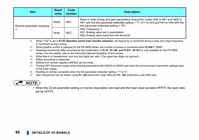
read value exceeds HFFFF, the reply data
(instruction codes H5E to H61 and HDE to g = "1", H11 to H23 and H91 to HA3 with the
s monitored during a stop and output frequency
itored when Pr.430 ≠ "9999".. (Pr.811 is only available for the FR-A800
nored.)
ack the communication parameter settings back
ruction code H9A) also.
ription
66 DETAILS OF I/O SIGNALS
NOTE • When the 32-bit parameter setting or monitor description are read and the
will be HFFFF.
Second parameter changing
Read H6CRead or write of bias and gain parameters HE1 with the link parameter extended settinlink parameter extended setting = "9").H00: Frequency H01: Analog value set in parametersH02: Analog value input from the terminal
Write HEC
When "100" is set in Pr.52 Operation panel main monitor selection, set frequency iis monitored during running.
When position control is selected for the FR-A800 series, the number of pulses is mon Displayed increments differ according to the combination of Pr.37, Pr.144, and Pr.811
series.) For the details, refer to the Instruction Manual (Detailed) of the inverter. Write data is in hexadecimal, and only two digits are valid. (The upper two digits are ig Differs according to capacities. Setting from remote registers (RWw0) can be made. Turning OFF the power supply while clearing parameters with H5A5A or H55AA sets b
to the initial values. Reading or writing is available when the link parameter extended setting = "1 or 9". Gain frequencies can be written using Pr. 125 (instruction code H99) and Pr. 126 (inst
Item Read/write
Codenumber Desc
DETAILS OF I/O SIGNALS 67
7
No. of the instruction code and monitor
mmunication dedicated monitor.tion of the monitor display in the Instruction
tput frequency) and H05 (set frequency) nd Pr.811. (Pr.811 is only available for the
7.2.4 Monitor codesInformation about the inverter can be monitored by setting the special monitor selectioncode using the remote registers, RWw26 to 2F.
NOTE • The monitor codes (monitor items) are the same as those of the RS-485 co
For the details of the monitor code and monitor description, refer to the secManual (Detailed) of the inverter.
• When the remote registers RWw26 to 2F are used for monitoring, H01 (oualways indicate the frequency regardless of the settings of Pr.37, Pr.144, aFR-A800 series.)
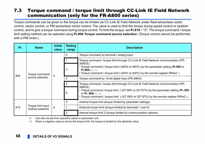
Link IE Field Network s)ork under Real sensorless vector
orque during speed control or position 810 = "2". The torque command / torque n. (Torque control cannot be performed
lue.
iption
ink IE Field Network communication (FR-
0%) by the parameter setting (Pr.805 or
0%) by the remote register RWw2
8AX)
ink IE Field Network communication (FR-
327.67%) by the parameter setting (Pr. 805
o 327.67%) by the remote register RWw2
ter settings)
als 1 and 4)
unication options)
68 DETAILS OF I/O SIGNALS
7.3 Torque command / torque limit through CC-communication (only for the FR-A800 serie
Torque commands can be given or the torque can be limited via CC-Link IE Field Netwcontrol, vector control, or PM sensorless vector control. The value is used to limit the tcontrol, and to give a torque command during torque control. To limit the torque, set Pr.limit setting method can be selected using Pr.804 Torque command source selectiowith a PM motor.)
Can also be set from operation panel or parameter unit. When a negative value is set as the torque limit, the torque is limited by the absolute va
Pr. Name Initialvalue
Settingrange Descr
804 Torque command source selection 0
0 Torque command by terminal1 analog input
1 Torque command / torque limit through CC-LA8NCE)• Torque command / torque limit (-400% to 40
Pr.806) , • Torque command / torque limit (-400% to 40
3
4 Torque command by 16-bit digital input (FR-A
5 Torque command / torque limit through CC-LA8NCE)• Torque command / torque limit (-327.68% to
or Pr. 806) , • Torque command / torque limit (-327.68% t
6
810 Torque limit input method selection 0
0 Internal torque limit (torque limited by parame
1 External torque limit (torque limited by termin
2 Internal torque limit 2 (torque limited by comm
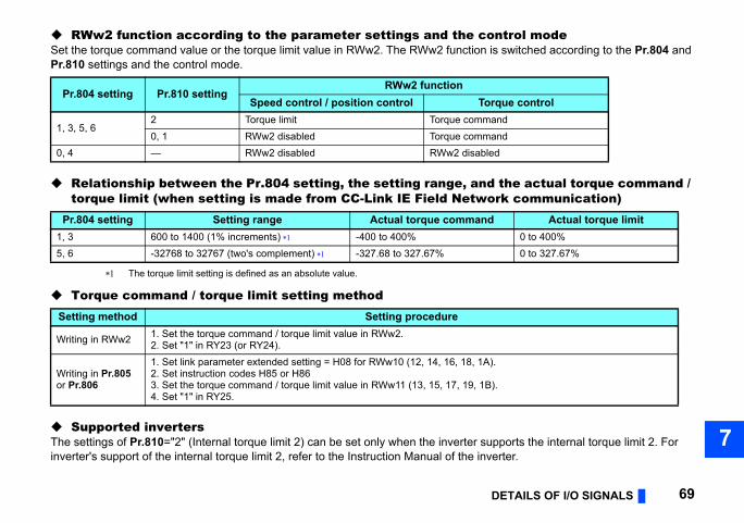
DETAILS OF I/O SIGNALS 69
7
ntrol modeis switched according to the Pr.804 and
the actual torque command / rk communication)
pports the internal torque limit 2. For erter.
rque controlandanded
Actual torque limit0 to 400%0 to 327.67%
).
).
RWw2 function according to the parameter settings and the coSet the torque command value or the torque limit value in RWw2. The RWw2 function Pr.810 settings and the control mode.
Relationship between the Pr.804 setting, the setting range, andtorque limit (when setting is made from CC-Link IE Field Netwo
The torque limit setting is defined as an absolute value.
Torque command / torque limit setting method
Supported invertersThe settings of Pr.810="2" (Internal torque limit 2) can be set only when the inverter suinverter's support of the internal torque limit 2, refer to the Instruction Manual of the inv
Pr.804 setting Pr.810 settingRWw2 function
Speed control / position control To
1, 3, 5, 62 Torque limit Torque comm0, 1 RWw2 disabled Torque comm
0, 4 — RWw2 disabled RWw2 disabl
Pr.804 setting Setting range Actual torque command1, 3 600 to 1400 (1% increments) -400 to 400%5, 6 -32768 to 32767 (two's complement) -327.68 to 327.67%
Setting method Setting procedure
Writing in RWw2 1. Set the torque command / torque limit value in RWw2.2. Set "1" in RY23 (or RY24).
Writing in Pr.805 or Pr.806
1. Set link parameter extended setting = H08 for RWw10 (12, 14, 16, 18, 1A2. Set instruction codes H85 or H863. Set the torque command / torque limit value in RWw11 (13, 15, 17, 19, 1B4. Set "1" in RY25.
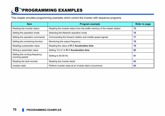
e programs.
Refer to page
aster station 75
76
77
78
79
80
81
83
84
70 PROGRAMMING EXAMPLES
8 PROGRAMMING EXAMPLES
This chapter provides programming examples which control the inverter with sequenc
Item Program example
Reading the inverter status Reading the inverter status from the buffer memory of the m
Setting the operation mode Selecting the Network operation mode
Setting the operation commands Commanding the forward rotation and middle speed signals
Setting the monitoring function Monitoring the output frequency
Reading a parameter value Reading the value of Pr.7 Acceleration time
Writing a parameter value Setting "3.0 s" in Pr.7 Acceleration time
Setting the running frequency(running speed) Setting to 50.00 Hz
Reading the fault records Reading the inverter faults
Inverter reset Perform inverter reset at an inverter alarm occurrence.
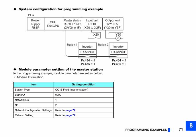
OGRAMMING EXAMPLES 718
PR
System configuration for programming example
Module parameter setting of the master stationIn the programming example, module parameter are set as below. • Module Information
Item Setting condition
Station Type CC IE Field (master station)
Start I/O 0000
Network No. 1
No. 2
Network Configuration Settings Refer to page 72
Refresh Setting Refer to page 72
PowersupplyR61P
CPUR04CPU
Master stationRJ71GF11-T2(X/Y00 to 1F)
Input unitRX10
(X20 to X2F)
Output unitRY10R2
(Y30 to Y3F)
Station 1 Inverter
FR-A8NCE
Pr.434 = 1Pr.435 = 1
Pr.434 = 1Pr.435 = 2
Station 2 Inverter
FR-A8NCE
PLC
X20 Y30
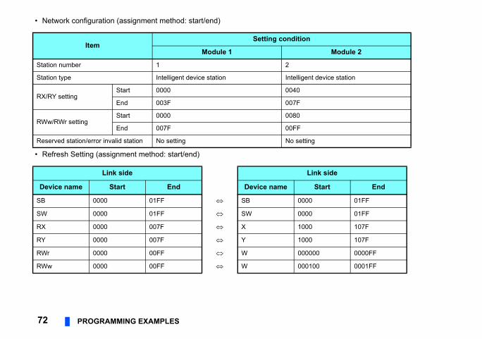
• Network configuration (assignment method: start/end)
Module 2
evice station
k side
tart End
01FF
01FF
107F
107F
0 0000FF
0 0001FF
72 PROGRAMMING EXAMPLES
• Refresh Setting (assignment method: start/end)
ItemSetting condition
Module 1
Station number 1 2
Station type Intelligent device station Intelligent d
RX/RY settingStart 0000 0040
End 003F 007F
RWw/RWr settingStart 0000 0080
End 007F 00FF
Reserved station/error invalid station No setting No setting
Link side Lin
Device name Start End Device name S
SB 0000 01FF SB 0000
SW 0000 01FF SW 0000
RX 0000 007F X 1000
RY 0000 007F Y 1000
RWr 0000 00FF W 00000
RWw 0000 00FF W 00010
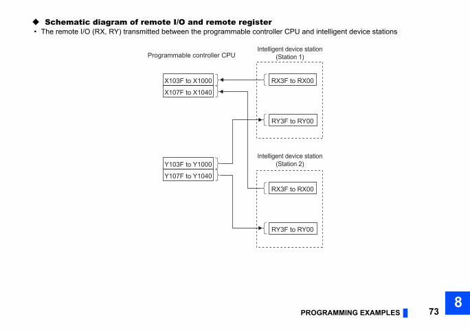
OGRAMMING EXAMPLES 738
d intelligent device stations
0
ation
ation
0
0
0
PR
Schematic diagram of remote I/O and remote register • The remote I/O (RX, RY) transmitted between the programmable controller CPU an
RX3F to RX0X103F to X1000
X107F to X1040
Y103F to Y1000
Y107F to Y1040
Programmable controller CPUIntelligent device st
(Station 1)
Intelligent device st(Station 2)
RY3F to RY0
RX3F to RX0
RY3F to RY0
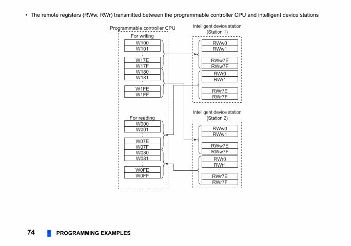
• The remote registers (RWw, RWr) transmitted between the programmable controller CPU and intelligent device stations
tation
tation
74 PROGRAMMING EXAMPLES
RWw0W100
Programmable controller CPUFor writing
RWw1W101
W17EW17FW180W181
RWw7ERWw7FRWr0
W000For reading
RWr1
W001
W07EW07F
W0FF
RWr7ERWr7F
W1FEW1FF
W080W081
W0FE
RWw0RWw1
RWw7ERWw7FRWr0RWr1
RWr7ERWr7F
Intelligent device s(Station 1)
Intelligent device s(Station 2)
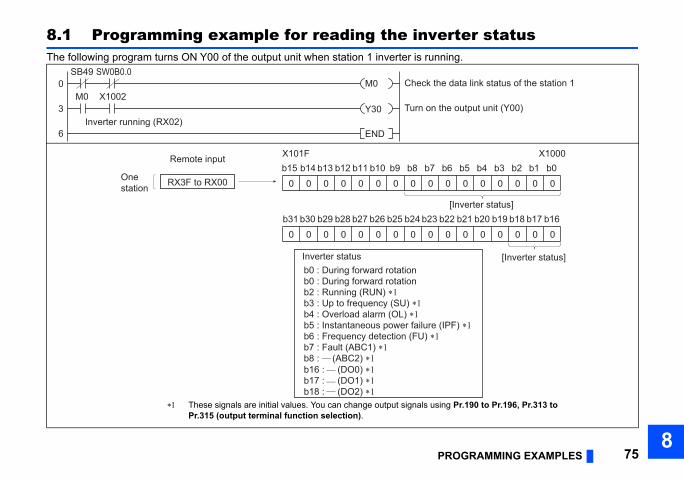
OGRAMMING EXAMPLES 758
ter statusng.
data link status of the station 1
output unit (Y00)
0 0 0 0 0 0
X1000b5 b4 b3 b2 b1 b0
[Inverter status]
F) ∗1
0 0 0 0 0 02 b21 b20 b19 b18 b17 b16
[Inverter status]
Pr.190 to Pr.196, Pr.313 to
PR
8.1 Programming example for reading the inverThe following program turns ON Y00 of the output unit when station 1 inverter is runni
M0
Y30
END
Check the SB49
0
3
6
M0 X1002Turn on the
Inverter running (RX02)
SW0B0.0
0 0 0 0 0 0 00 0 0b15X101F
b14 b13 b12 b11 b10 b9 b8 b7 b6
Inverter statusb0 : During forward rotationb0 : During forward rotationb2 : Running (RUN) ∗1b3 : Up to frequency (SU) ∗1b4 : Overload alarm (OL) ∗1b5 : Instantaneous power failure (IPb6 : Frequency detection (FU) ∗1b7 : Fault (ABC1) ∗1
b16 : (DO0) ∗1b17 : (DO1) ∗1b18 : (DO2) ∗1
b8 : (ABC2) ∗1
Onestation
Remote input
0 0 0 0 0 0 00 0 0b31 b30 b29 b28 b27 b26 b25 b24 b23 b2
RX3F to RX00
These signals are initial values. You can change output signals usingPr.315 (output terminal function selection).
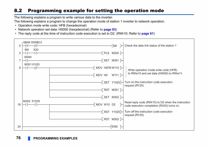
tion mode
network operation.
to page 61)
peration mode write code (HFB)10 and set data (H0000) to RWw11.
e instruction code executionY25)
e instruction code executionY25)
y code (RWr10) to D2 when the instructionution completion (RX25) turns on.
data link status of the station 1
76 PROGRAMMING EXAMPLES
8.2 Programming example for setting the operaThe following explains a program to write various data to the inverter.The following explains a program to change the operation mode of station 1 inverter to • Operation mode write code: HFB (hexadecimal) • Network operation set data: H0000 (hexadecimal) (Refer to page 63) • The reply code at the time of instruction code execution is set to D2. (RWr10: Refer
SET M301
PLS M300
M301
MOV W10 D2
MOV H0FB W110Write oto RWw
SET Y1025
Turn off threquest (R
0
9
M0 X20
X1025
M300
RST M301
SET M302M302
18
RST Y1025
RST M302
END24
3
7
Turn on threquest (R
MOV H0 W111
Read replcode exec
SB49
X1025
SW0B0.0M0 Check the
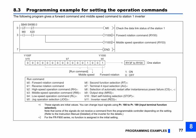
OGRAMMING EXAMPLES 778
tion commandsn 1 inverter
tation command (RY00)
ed operation command (RY03)
data link status of the station 1
ONOFF
One station3F to RY00
r instantaneous power failure (CS)∗1, ∗2
P)∗1
Pr. 189 (input terminal function
ble controller depending on the setting.
PR
8.3 Programming example for setting the operaThe following program gives a forward command and middle speed command to statio
Forward ro
SB49
M0 X200
3
7
Middle spe
Y1000
END
Y1003
Check the M0SW0B0.0
0 0 0 0 000 0 0 0 0 0 1 0 0 1b15 b0
Y100F Y1000b7
[Run command]Forward rotation
1:0:Middle speed
RY
Run commandb0 : Forward rotation command
b5 : Jog operation selection (JOG)∗1
b1 : Reverse rotation commandb6 : Second function selection (RT)∗1
b2 : High-speed operation command (RH)∗1b7 : Terminal 4 input selection (AU)∗1
b3 : Middle-speed operation command (RM)∗1b8 : Selection of automatic restart afte
b10 : Start self-holding selection (STOb11 : Inverter reset (RES)∗1
b4 : Low-speed operation command (RL)∗1b9 : Output stop (MRS)∗1
These signals are initial values. You can change input signals using Pr. 180 toselection).Note that some of the signals do not receive a command from the programma(Refer to the Instruction Manual (Detailed) of the inverter for the details.)
For the FR-F800 series, no function is assigned in the initial setting.
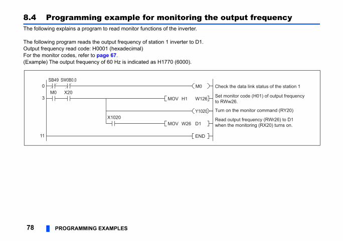
utput frequency
onitor code (H01) of output frequencyw26.
on the monitor command (RY20)
output frequency (RWr26) to D1 the monitoring (RX20) turns on.
k the data link status of the station 1
78 PROGRAMMING EXAMPLES
8.4 Programming example for monitoring the oThe following explains a program to read monitor functions of the inverter.
The following program reads the output frequency of station 1 inverter to D1.Output frequency read code: H0001 (hexadecimal)For the monitor codes, refer to page 67.(Example) The output frequency of 60 Hz is indicated as H1770 (6000).
SB49
Set mto RWMOV H1 W126
Turn
MOV W26 D1Readwhen
END11
3
0
X1020
M0 X20
Y1020
ChecM0SW0B0.0
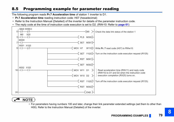
OGRAMMING EXAMPLES 798
g
r instruction code. to page 61)
extended settings (set them to other than
e (H07) to RWw10.
ion code execution request (RY25)
ion code execution request (RY25)
n time (RWr11) and reply coded D2 when the instruction codetion (RX25) turns on.
status of the station 1
PR
8.5 Programming example for parameter readinThe following program reads Pr.7 Acceleration time of station 1 inverter to D1. • Pr.7 Acceleration time reading instruction code: H07 (hexadecimal) • Refer to the Instruction Manual (Detailed) of the inverter for details of the paramete • The reply code at the time of instruction code execution is set to D2. (RWr10: Refer
NOTE • For parameters having numbers 100 and later, change their link parameter
H00). Refer to the Instruction Manual (Detailed) of the inverter.
SET M301
PLS M300
M301
MOV W11 D1
MOV H7 W110 Write Pr. 7 read cod
RST M301
Turn off the instruct
0
3
7
9
16
24
M0 X20
X1025
X1025
SB49
M300
SET M302
SET Y1025
M302
MOV W10 D2
RST Y1025
RST M302
END
Turn on the instruct
Read acceleratio(RWr10) to D1 anexecution comple
Check the data linkM0SW0B0.0
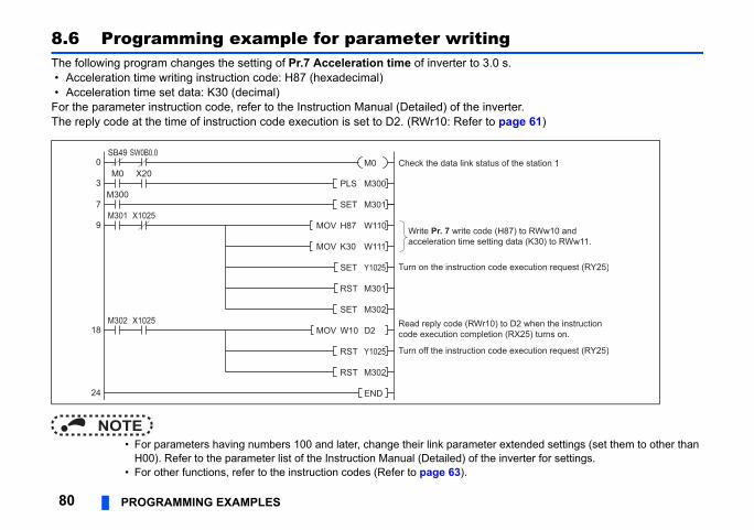
g s.
erter. page 61)
extended settings (set them to other than inverter for settings.
(H87) to RWw10 andg data (K30) to RWw11.
de execution request (RY25)
de execution request (RY25)
) to D2 when the instructionn (RX25) turns on.
s of the station 1
80 PROGRAMMING EXAMPLES
8.6 Programming example for parameter writinThe following program changes the setting of Pr.7 Acceleration time of inverter to 3.0 • Acceleration time writing instruction code: H87 (hexadecimal) • Acceleration time set data: K30 (decimal)For the parameter instruction code, refer to the Instruction Manual (Detailed) of the invThe reply code at the time of instruction code execution is set to D2. (RWr10: Refer to
NOTE • For parameters having numbers 100 and later, change their link parameter
H00). Refer to the parameter list of the Instruction Manual (Detailed) of the • For other functions, refer to the instruction codes (Refer to page 63).
SET M301
PLS M300
MOV W10 D2
MOV H87 W110 Write Pr. 7 write code acceleration time settin
SET Y1025
Turn off the instruction co
0
3
7
9
18
24
M0 X20
X1025M301
SB49
X1025
M300
SET M302M302
RST Y1025
RST M302
END
Turn on the instruction co
MOV K30 W111
RST M301
Read reply code (RWr10code execution completio
Check the data link statuM0SW0B0.0
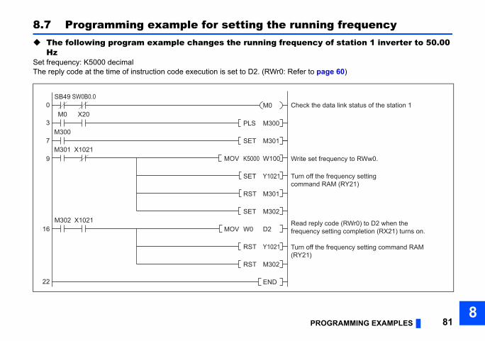
OGRAMMING EXAMPLES 818
ng frequencyy of station 1 inverter to 50.00
age 60)
frequency to RWw0.
e frequency setting command RAM
e frequency setting RAM (RY21)
ly code (RWr0) to D2 when the setting completion (RX21) turns on.
data link status of the station 1
PR
8.7 Programming example for setting the runni The following program example changes the running frequenc
HzSet frequency: K5000 decimalThe reply code at the time of instruction code execution is set to D2. (RWr0: Refer to p
SET M301
PLS M300
M301
MOV W0 D2
MOV K5000 W100 Write set
SET Y1021
Turn off th(RY21)
0
3
7
9
16
22
RST M301
M0 X20
X1021
SB49
M302 X1021
M300
SET M302
RST Y1021
RST M302
END
Turn off thcommand
Read repfrequency
Check theM0SW0B0.0
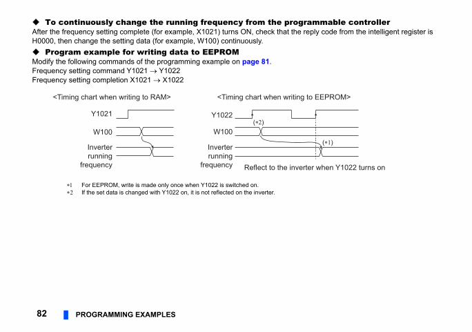
mmable controllerply code from the intelligent register is
(∗1)
r when Y1022 turns on
EEPROM>
82 PROGRAMMING EXAMPLES
To continuously change the running frequency from the prograAfter the frequency setting complete (for example, X1021) turns ON, check that the reH0000, then change the setting data (for example, W100) continuously. Program example for writing data to EEPROMModify the following commands of the programming example on page 81.Frequency setting command Y1021 Y1022Frequency setting completion X1021 X1022
For EEPROM, write is made only once when Y1022 is switched on. If the set data is changed with Y1022 on, it is not reflected on the inverter.
<Timing chart when writing to RAM>
Y1021
W100
Inverterrunning
frequency
Y1022(∗2)
W100
Inverterrunning
frequency Reflect to the inverte
<Timing chart when writing to
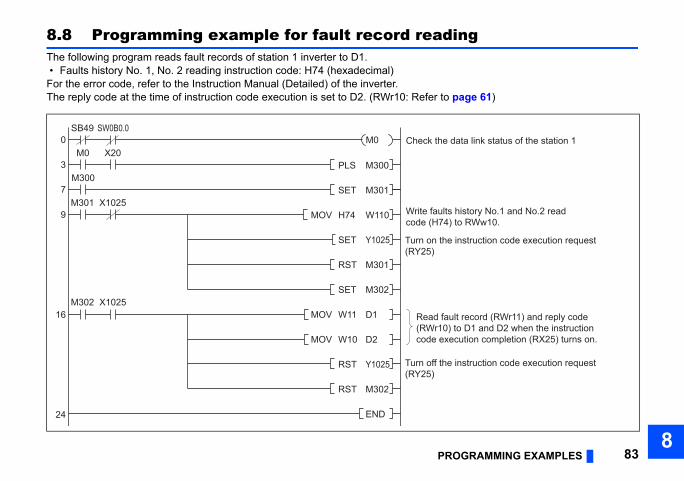
OGRAMMING EXAMPLES 838
ing
page 61)
history No.1 and No.2 read) to RWw10.
instruction code execution request
instruction code execution request
ult record (RWr11) and reply code to D1 and D2 when the instructionecution completion (RX25) turns on.
data link status of the station 1
PR
8.8 Programming example for fault record readThe following program reads fault records of station 1 inverter to D1. • Faults history No. 1, No. 2 reading instruction code: H74 (hexadecimal)For the error code, refer to the Instruction Manual (Detailed) of the inverter.The reply code at the time of instruction code execution is set to D2. (RWr10: Refer to
SET M301
PLS M300
MOV W11 D1
MOV H74 W110 Write faultscode (H74
SET Y1025
Turn off the(RY25)
0
3
7
9
16
24
M0 X20
X1025
SB49
M302 X1025
M301
M300
RST M301
SET M302
MOV W10 D2
RST Y1025
RST M302
END
Turn on the(RY25)
Read fa(RWr10)code ex
Check the M0SW0B0.0
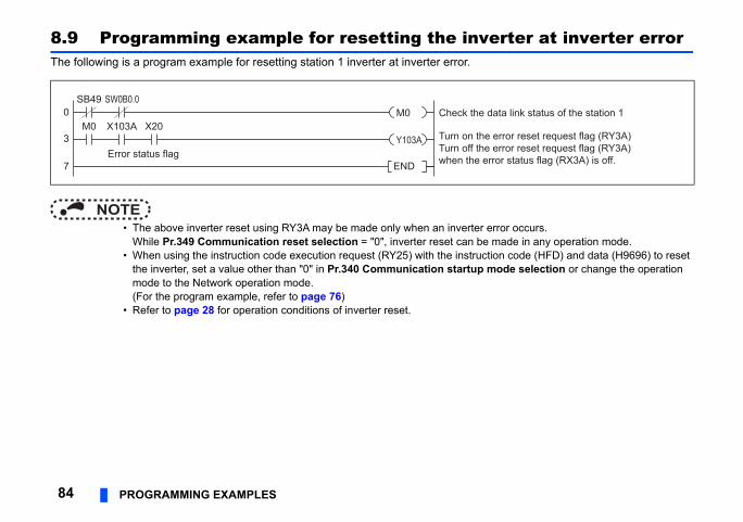
erter at inverter error
rror occurs. made in any operation mode. tion code (HFD) and data (H9696) to reset
ode selection or change the operation
data link status of the station 1
error reset request flag (RY3A) error reset request flag (RY3A)rror status flag (RX3A) is off.
84 PROGRAMMING EXAMPLES
8.9 Programming example for resetting the invThe following is a program example for resetting station 1 inverter at inverter error.
NOTE • The above inverter reset using RY3A may be made only when an inverter e
While Pr.349 Communication reset selection = "0", inverter reset can be • When using the instruction code execution request (RY25) with the instruc
the inverter, set a value other than "0" in Pr.340 Communication startup mmode to the Network operation mode. (For the program example, refer to page 76)
• Refer to page 28 for operation conditions of inverter reset.
SB49
M0 X103A X200
3
7 END
Check the
Error status flag
Turn on theTurn off thewhen the e
Y103A
M0SW0B0.0
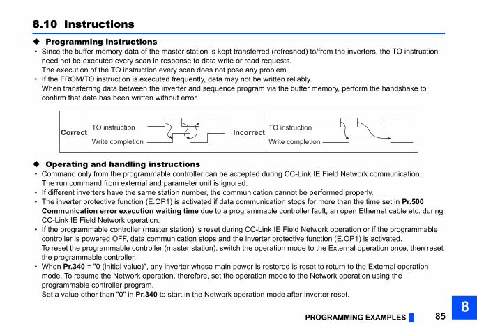
OGRAMMING EXAMPLES 858
/from the inverters, the TO instruction
emory, perform the handshake to
IE Field Network communication.
erformed properly.r more than the time set in Pr.500 ault, an open Ethernet cable etc. during
ork operation or if the programmable ction (E.OP1) is activated.
the External operation once, then reset
t to return to the External operation etwork operation using the
erter reset.
on
PR
8.10 Instructions Programming instructions • Since the buffer memory data of the master station is kept transferred (refreshed) to
need not be executed every scan in response to data write or read requests. The execution of the TO instruction every scan does not pose any problem.
• If the FROM/TO instruction is executed frequently, data may not be written reliably.When transferring data between the inverter and sequence program via the buffer mconfirm that data has been written without error.
Operating and handling instructions • Command only from the programmable controller can be accepted during CC-Link
The run command from external and parameter unit is ignored. • If different inverters have the same station number, the communication cannot be p • The inverter protective function (E.OP1) is activated if data communication stops fo
Communication error execution waiting time due to a programmable controller fCC-Link IE Field Network operation.
• If the programmable controller (master station) is reset during CC-Link IE Field Netwcontroller is powered OFF, data communication stops and the inverter protective funTo reset the programmable controller (master station), switch the operation mode tothe programmable controller.
• When Pr.340 = "0 (initial value)", any inverter whose main power is restored is resemode. To resume the Network operation, therefore, set the operation mode to the Nprogrammable controller program.Set a value other than "0" in Pr.340 to start in the Network operation mode after inv
TO instruction
Write completion
TO instruction
Write completiCorrect Incorrect
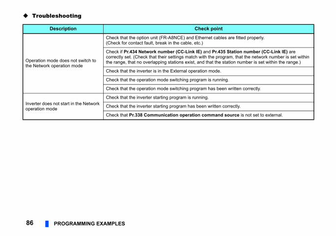
t
les are fitted properly.
35 Station number (CC-Link IE) are gram, that the network number is set within
station number is set within the range.)
ing.
en written correctly.
correctly.
d source is not set to external.
86 PROGRAMMING EXAMPLES
Troubleshooting
Description Check poin
Operation mode does not switch to the Network operation mode
Check that the option unit (FR-A8NCE) and Ethernet cab(Check for contact fault, break in the cable, etc.)
Check if Pr.434 Network number (CC-Link IE) and Pr.4correctly set. (Check that their settings match with the prothe range, that no overlapping stations exist, and that the
Check that the inverter is in the External operation mode.
Check that the operation mode switching program is runn
Check that the operation mode switching program has be
Inverter does not start in the Network operation mode
Check that the inverter starting program is running.
Check that the inverter starting program has been written
Check that Pr.338 Communication operation comman
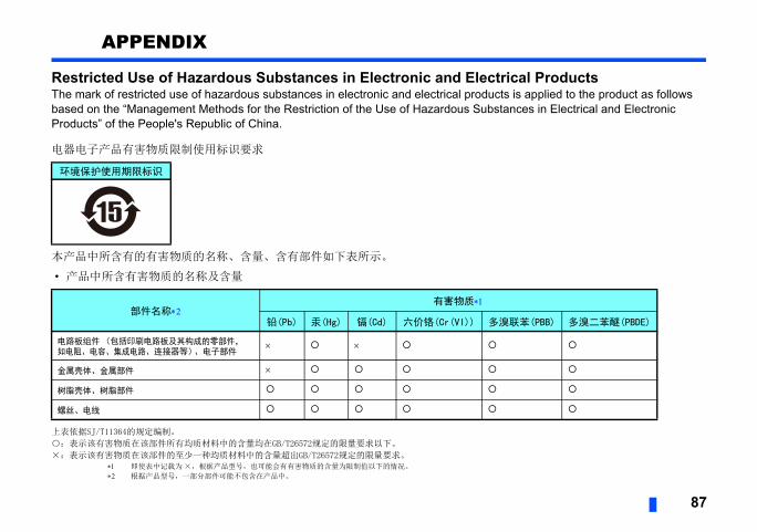
87
APPENDIX
Restricted Use of Hazardous Substances in Electronic and Electrical ProductsThe mark of restricted use of hazardous substances in electronic and electrical products is applied to the product as follows based on the “Management Methods for the Restriction of the Use of Hazardous Substances in Electrical and Electronic Products” of the People's Republic of China.
电器电子产品有害物质限制使用标识要求
本产品中所含有的有害物质的名称、含量、含有部件如下表所示。
• 产品中所含有害物质的名称及含量
上表依据SJ/T11364的规定编制。
○:表示该有害物质在该部件所有均质材料中的含量均在GB/T26572规定的限量要求以下。
×:表示该有害物质在该部件的至少一种均质材料中的含量超出GB/T26572规定的限量要求。 即使表中记载为 ×,根据产品型号,也可能会有有害物质的含量为限制值以下的情况。
根据产品型号,一部分部件可能不包含在产品中。
环境保护使用期限标识
部件名称有害物质
铅(Pb) 汞(Hg) 镉(Cd) 六价铬(Cr(VI)) 多溴联苯(PBB) 多溴二苯醚(PBDE)
电路板组件(包括印刷电路板及其构成的零部件,如电阻、电容、集成电路、连接器等)、电子部件
金属壳体、金属部件
树脂壳体、树脂部件
螺丝、电线
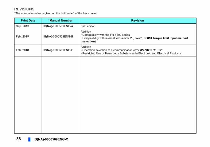
88 IB(NA)-0600509ENG-C
REVISIONS*The manual number is given on the bottom left of the back cover.
Print Date *Manual Number Revision
Sep. 2013 IB(NA)-0600509ENG-A First edition
Feb. 2015 IB(NA)-0600509ENG-B
Addition• Compatibility with the FR-F800 series• Compatibility with internal torque limit 2 (RWw2, Pr.810 Torque limit input method
selection)
Feb. 2018 IB(NA)-0600509ENG-CAddition• Operation selection at a communication error (Pr.502 = "11, 12")• Restricted Use of Hazardous Substances in Electronic and Electrical Products

FR-A8NCE INSTRUCTION M
ANUAL
C
INVERTER
INVERTER
PRE-OPERATION INSTRUCTIONS 1INSTALLATION 2WIRING 3INVERTER SETTING 4FUNCTION OVERVIEW 5I/O SIGNAL LIST 6DETAILS OF I/O SIGNALS 7PROGRAMMING EXAMPLES 8
INVERTERPlug-in option
INSTRUCTION MANUAL
HEAD OFFICE: TOKYO BUILDING 2-7-3, MARUNOUCHI, CHIYODA-KU, TOKYO 100-8310, JAPAN
FR-A8NCE
Network communication function
IB(NA)-0600509ENG-C(1802) MEE Printed in Japan Specifications subject to change without notice.