Embed Size (px)
Citation preview
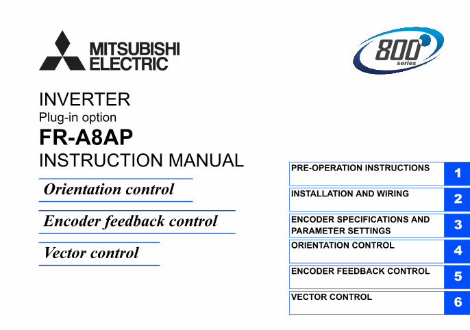
INVERTERPlug-in option
INSTRUCTION MANUAL PRE-OPERATION INSTRUCTIONS 1INSTALLATION AND WIRING 2ENCODER SPECIFICATIONS AND PARAMETER SETTINGS 3ORIENTATION CONTROL 4ENCODER FEEDBACK CONTROL 5VECTOR CONTROL 6
FR-A8AP
Orientation control
Encoder feedback control
Vector control

1
Thank you for choosing this Mitsubishi inverter plug-in option.orrect handling might cause an unexpected orrectly.
Instruction Manual and appended a full knowledge of the equipment, safety into "Warning" and "Caution".r severe injury.
or slight injury, or may cause only material
. Both instruction levels must be followed
front cover or the wiring cover removed. Otherwise ck.uld be when performing wiring and periodic
on who is involved in wiring or inspection shall wait ge using a tester or the like. For some time after the
lectric shock.
amage, etc. may occur.
se devices may cause a burn.
This Instruction Manual provides handling information and precautions for use of this product. Incfault. Before using this product, always read this Instruction Manual carefully to use this product cPlease forward this Instruction Manual to the end user.
Electric Shock Prevention
Injury Prevention
Safety instructionsDo not attempt to install, operate, maintain or inspect the product until you have read through thisdocuments carefully and can use the equipment correctly. Do not use this product until you haveinformation and instructions. In this Instruction Manual, the safety instruction levels are classified
Incorrect handling may cause hazardous conditions, resulting in death o
Incorrect handling may cause hazardous conditions, resulting in mediumdamage.
The level may even lead to a serious consequence according to conditions
because these are important to personal safety.
Warning While the inverter power is ON, do not open the front cover or the wiring cover. Do not run the inverter with the
you may access the exposed high voltage terminals or the charging part of the circuitry and get an electric sho Do not remove the inverter front cover even if the power supply is disconnected. The only exception for this wo
inspection. You may accidentally touch the charged inverter circuits and get an electric shock. Before wiring or inspection, LED indication of the inverter unit operation panel must be switched OFF. Any pers
for at least 10 minutes after the power supply has been switched OFF and check that there is no residual voltapower-OFF, a high voltage remains in the smoothing capacitor, and it is dangerous.
Any person who is involved in wiring or inspection of this equipment shall be fully competent to do the work. The plug-in option must be installed before wiring. Otherwise you may get an electric shock or be injured. Do not touch the plug-in option or handle the cables with wet hands. Otherwise you may get an electric shock. Do not subject the cables to scratches, excessive stress, heavy loads or pinching. Otherwise you may get an e
Caution The voltage applied to each terminal must be the ones specified in the Instruction Manual. Otherwise a burst, d The cables must be connected to the correct terminals. Otherwise a burst, damage, etc. may occur. The polarity (+ and -) must be correct. Otherwise a burst or damage may occur. While power is ON or for some time after power OFF, do not touch the inverter as it will be extremely hot. Touching the
Warning
Caution
Caution
Additional Instructionse unexpected fault, an injury, or an electric
ents or other flammable substance such as oil.uct will be damaged. Halogen-based materials are esidual fumigant components from being infiltrated kaging. Sterilization of disinfection of wooden
machines to make unexpected motions.
e product.
tarting operations. Because all parameters return to
n for explanation. Never operate the inverter in this erating the inverter.
2
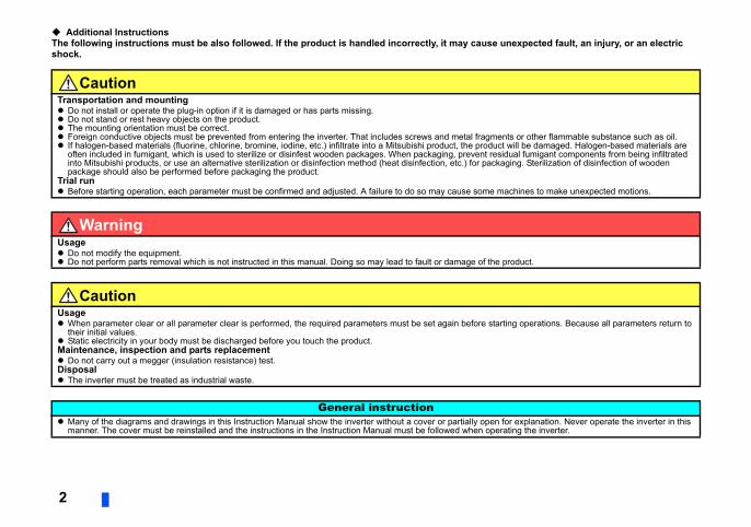
The following instructions must be also followed. If the product is handled incorrectly, it may causshock.
CautionTransportation and mounting Do not install or operate the plug-in option if it is damaged or has parts missing. Do not stand or rest heavy objects on the product. The mounting orientation must be correct. Foreign conductive objects must be prevented from entering the inverter. That includes screws and metal fragm If halogen-based materials (fluorine, chlorine, bromine, iodine, etc.) infiltrate into a Mitsubishi product, the prod
often included in fumigant, which is used to sterilize or disinfest wooden packages. When packaging, prevent rinto Mitsubishi products, or use an alternative sterilization or disinfection method (heat disinfection, etc.) for pacpackage should also be performed before packaging the product.
Trial run Before starting operation, each parameter must be confirmed and adjusted. A failure to do so may cause some
WarningUsage Do not modify the equipment. Do not perform parts removal which is not instructed in this manual. Doing so may lead to fault or damage of th
CautionUsage When parameter clear or all parameter clear is performed, the required parameters must be set again before s
their initial values. Static electricity in your body must be discharged before you touch the product.Maintenance, inspection and parts replacement Do not carry out a megger (insulation resistance) test.Disposal The inverter must be treated as industrial waste.
General instruction Many of the diagrams and drawings in this Instruction Manual show the inverter without a cover or partially ope
manner. The cover must be reinstalled and the instructions in the Instruction Manual must be followed when op
3
— CONTENTS —
5
...................................................5
...................................................6
7
...................................................7
...................................................7
.................................................10
.................................................12
.................................................15
.................................................16
17
.................................................17
.................................................19........................................................19.......................................................20
21
.................................................21
.................................................23
.................................................24
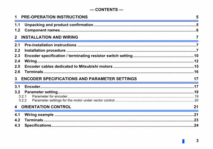
1 PRE-OPERATION INSTRUCTIONS
1.1 Unpacking and product confirmation ...........................................1.2 Component names..........................................................................
2 INSTALLATION AND WIRING
2.1 Pre-installation instructions ..........................................................2.2 Installation procedure ....................................................................2.3 Encoder specification / terminating resistor switch setting.......2.4 Wiring...............................................................................................2.5 Encoder cables dedicated to Mitsubishi motors .........................2.6 Terminals .........................................................................................
3 ENCODER SPECIFICATIONS AND PARAMETER SETTINGS
3.1 Encoder............................................................................................3.2 Parameter setting............................................................................
3.2.1 Parameter for encoder..........................................................................3.2.2 Parameter settings for the motor under vector control ..........................
4 ORIENTATION CONTROL
4.1 Wiring example ...............................................................................4.2 Terminals .........................................................................................4.3 Specifications..................................................................................
5 ENCODER FEEDBACK CONTROL 25
.................................................25
.................................................26
27
.................................................27
.................................................31
4
5.1 Wiring examples .............................................................................5.2 Specifications..................................................................................
6 VECTOR CONTROL
6.1 Wiring examples .............................................................................6.2 Specifications..................................................................................
ERATION INSTRUCTIONS 5
1
he product is as you ordered and intact.
of the input terminals as sink logic, unless Detailed) of the inverter.)
o page 7.)
PRE-OP
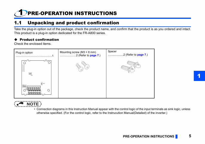
1 PRE-OPERATION INSTRUCTIONS
1.1 Unpacking and product confirmationTake the plug-in option out of the package, check the product name, and confirm that tThis product is a plug-in option dedicated for the FR-A800 series.
Product confirmationCheck the enclosed items.
NOTE • Connection diagrams in this Instruction Manual appear with the control logic
otherwise specified. (For the control logic, refer to the Instrucution Manual(
Plug-in option...............................................1
Mounting screw (M3 × 8 mm).....................2 (Refer to page 7.)
Spacer....................2 (Refer t
1 2 3 4
O N
12
ON
SW2
SW3
SW1
Refer to page
r installs spacers. 712
river/ complementary). 10―
resistor. 10
1 and 2 are OFF .) ―
ter. 7
Rear view (g)
(a)
(a)
12
ON
6 PRE-OPERATION INSTRUCTIONS
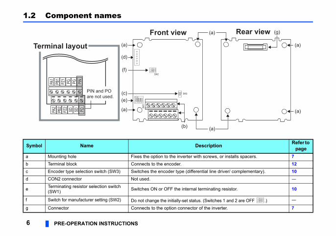
1.2 Component names
Symbol Name Description
a Mounting hole Fixes the option to the inverter with screws, ob Terminal block Connects to the encoder.c Encoder type selection switch (SW3) Switches the encoder type (differential line dd CON2 connector Not used.
e Terminating resistor selection switch (SW1) Switches ON or OFF the internal terminating
f Switch for manufacturer setting (SW2) Do not change the initially-set status. (Switchesg Connector Connects to the option connector of the inver
Front view
Terminal layoutPA
2PB
2PZ
2SD SD PO
PA1
PB1
PZ1
PG PG PIN
PIN and POare not used.
12
ON
SW2
SW3
SW1
(a)
(b) (a)
(a)
(a)
(e)
(d)
(f)
(c)
1 2 3 4
O N
TALLATION AND WIRING 7
2
verter or plug-in option.u touch the product.
Spacer
Inverter sideoption connector
le of installation to connector 1
INS
2 INSTALLATION AND WIRING
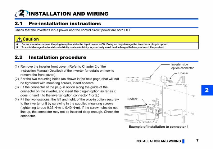
2.1 Pre-installation instructionsCheck that the inverter's input power and the control circuit power are both OFF.
2.2 Installation procedure
(1) Remove the inverter front cover. (Refer to Chapter 2 of the Instruction Manual (Detailed) of the inverter for details on how to remove the front cover.)
(2) For the two mounting holes (as shown in the next page) that will not be tightened with mounting screws, insert spacers.
(3) Fit the connector of the plug-in option along the guide of the connector on the inverter, and insert the plug-in option as far as it goes. (Insert it to the inverter option connector 1 or 2.)
(4) Fit the two locations, the left and right, of the plug-in option securely to the inverter unit by screwing in the supplied mounting screws (tightening torque 0.33 N·m to 0.40 N·m). If the screw holes do not line up, the connector may not be inserted deep enough. Check the connector.
Caution Do not mount or remove the plug-in option while the input power is ON. Doing so may damage the in To avoid damage due to static electricity, static electricity in your body must be discharged before yo
Spacer
Examp
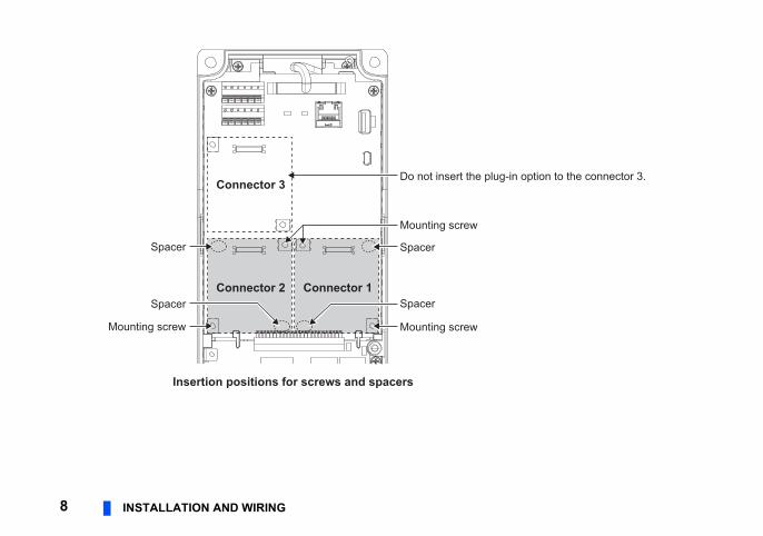
-in option to the connector 3.
8 INSTALLATION AND WIRING
Spacer
Spacer
Mounting screw
Do not insert the plug
Mounting screw
Spacer
Spacer
Mounting screw
Connector 1Connector 2
Connector 3
Insertion positions for screws and spacers
TALLATION AND WIRING 9
2
ounting the plug-in option.re mounted, priority is given to option er priority do not function. (For the
mproper installation, etc., the protective to the mounted position (option connector
ight, then pull it straight out. Pressure
INS
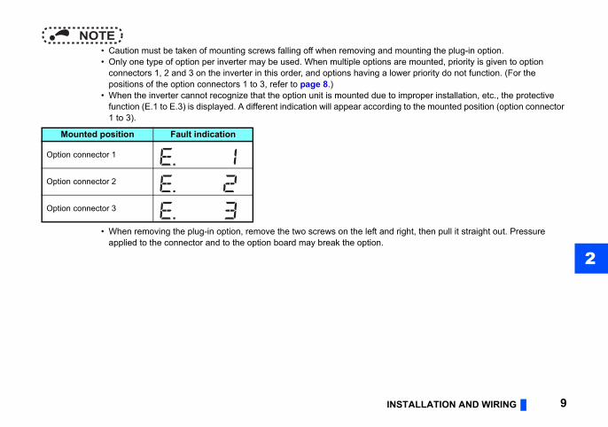
NOTE • Caution must be taken of mounting screws falling off when removing and m • Only one type of option per inverter may be used. When multiple options a
connectors 1, 2 and 3 on the inverter in this order, and options having a lowpositions of the option connectors 1 to 3, refer to page 8.)
• When the inverter cannot recognize that the option unit is mounted due to ifunction (E.1 to E.3) is displayed. A different indication will appear according1 to 3).
• When removing the plug-in option, remove the two screws on the left and rapplied to the connector and to the option board may break the option.
Mounted position Fault indication
Option connector 1
Option connector 2
Option connector 3
switch setting
Complementary
Differential line driver (initial status)
SW3
rminatingNtus)
rminating FF
12
ON
SW2
SW3
SW1
1 2 3 4
O N
10 INSTALLATION AND WIRING
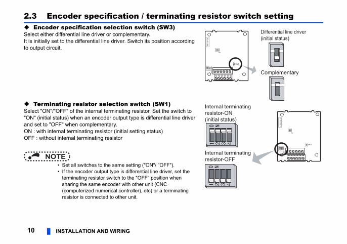
2.3 Encoder specification / terminating resistor Encoder specification selection switch (SW3)Select either differential line driver or complementary.It is initially set to the differential line driver. Switch its position according to output circuit.
Terminating resistor selection switch (SW1)Select "ON"/"OFF" of the internal terminating resistor. Set the switch to "ON" (initial status) when an encoder output type is differential line driver and set to "OFF" when complementary.ON : with internal terminating resistor (initial setting status)OFF : without internal terminating resistor
NOTE • Set all switches to the same setting ("ON"/ "OFF"). • If the encoder output type is differential line driver, set the
terminating resistor switch to the "OFF" position when sharing the same encoder with other unit (CNC (computerized numerical controller), etc) or a terminating resistor is connected to other unit.
12
ON
SW2
SW1
1 2 3 4
O N
Internal teresistor-O(initial sta
Internal teresistor-O
TALLATION AND WIRING 11
2
Motor used and switch setting
).
nating resistor on switch (SW1)
Power specifications
5 V
5 V
5 V
5 V
12 V
INS
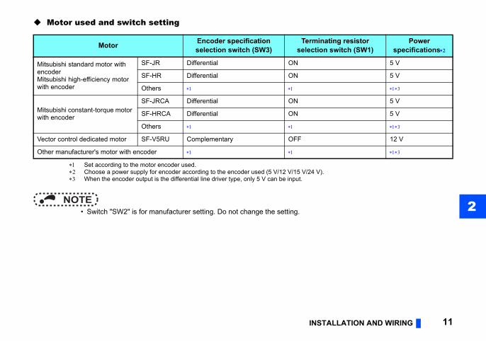
Set according to the motor encoder used. Choose a power supply for encoder according to the encoder used (5 V/12 V/15 V/24 V When the encoder output is the differential line driver type, only 5 V can be input.
NOTE • Switch "SW2" is for manufacturer setting. Do not change the setting.
Motor Encoder specification selection switch (SW3)
Termiselecti
Mitsubishi standard motor with encoderMitsubishi high-efficiency motor with encoder
SF-JR Differential ON
SF-HR Differential ON
Others
Mitsubishi constant-torque motor with encoder
SF-JRCA Differential ON
SF-HRCA Differential ON
Others
Vector control dedicated motor SF-V5RU Complementary OFF
Other manufacturer's motor with encoder
sition detector.
refer to page 15..
SDPG
GFDCBA
RS
Encoder
2mm2
FR-A800(FR-A8AP)
PZ2PZ1PB2PB1PA2PA1
Example of parallel connection with two cables
(with complementary encoder output)
Encoder cableShield
P clip
g (grounding) example using a P clip
12 INSTALLATION AND WIRING
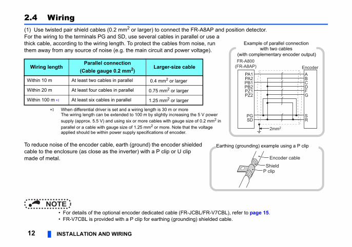
2.4 Wiring(1) Use twisted pair shield cables (0.2 mm2 or larger) to connect the FR-A8AP and poFor the wiring to the terminals PG and SD, use several cables in parallel or use a thick cable, according to the wiring length. To protect the cables from noise, run them away from any source of noise (e.g. the main circuit and power voltage).
When differential driver is set and a wiring length is 30 m or moreThe wiring length can be extended to 100 m by slightly increasing the 5 V power supply (approx. 5.5 V) and using six or more cables with gauge size of 0.2 mm2 in parallel or a cable with gauge size of 1.25 mm2 or more. Note that the voltage applied should be within power supply specifications of encoder.
To reduce noise of the encoder cable, earth (ground) the encoder shielded cable to the enclosure (as close as the inverter) with a P clip or U clip made of metal.
NOTE • For details of the optional encoder dedicated cable (FR-JCBL/FR-V7CBL), • FR-V7CBL is provided with a P clip for earthing (grounding) shielded cable
Wiring lengthParallel connection
(Cable gauge 0.2 mm2)Larger-size cable
Within 10 m At least two cables in parallel 0.4 mm2 or larger
Within 20 m At least four cables in parallel 0.75 mm2 or larger
Within 100 m At least six cables in parallel 1.25 mm2 or larger
Earthin
TALLATION AND WIRING 13
2
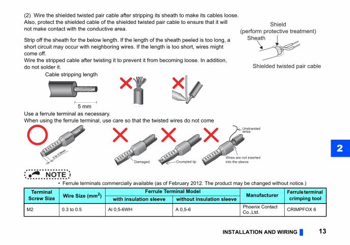
(2) Wire the shielded twisted pair cable after stripping its sheath to make its cables loose.
t may be changed without notice.)
Manufacturer Ferrule terminal crimping toolve
Phoenix Contact Co.,Ltd. CRIMPFOX 6
Sheath
Shield(perform protective treatment)
Shielded twisted pair cable
res are not insertedo the sleeve
Unstrandedwires
INS
Also, protect the shielded cable of the shielded twisted pair cable to ensure that it will not make contact with the conductive area.
Strip off the sheath for the below length. If the length of the sheath peeled is too long, ashort circuit may occur with neighboring wires. If the length is too short, wires might come off.Wire the stripped cable after twisting it to prevent it from becoming loose. In addition, do not solder it.
Use a ferrule terminal as necessary.When using the ferrule terminal, use care so that the twisted wires do not come
NOTE • Ferrule terminals commercially available (as of February 2012. The produc
Cable stripping length
Terminal Screw Size Wire Size (mm2)
Ferrule Terminal Modelwith insulation sleeve without insulation slee
M2 0.3 to 0.5 Al 0,5-6WH A 0,5-6
5 mm
Crumpled tipWiintDamaged
WireWire
SleeveSleeve
0 to 0.5mm
0 to 0.5mm
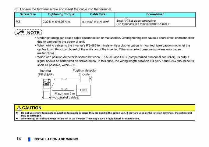
(3) Loosen the terminal screw and insert the cable into the terminal.
ing can cause a short circuit or malfunction
n is mounted, take caution not to let the ctromagnetic noises may cause
terized numerical controller), its output between FR-A8AP and CNC should be as
Screwdriver
de screwdriver4 mm/tip width: 2.5 mm )
used as the junction terminals, the option unit
n.
14 INSTALLATION AND WIRING
NOTE • Undertightening can cause cable disconnection or malfunction. Overtighten
due to damage to the screw or unit. • When wiring cables to the inverter's RS-485 terminals while a plug-in optio
cables touch the circuit board of the option or of the inverter. Otherwise, elemalfunctions.
• When one position detector is shared between FR-A8AP and CNC (compusignal should be connected as shown below. In this case, the wiring length short as possible, within 5 m.
Screw Size Tightening Torque Cable Size
M2 0.22 Nm to 0.25 Nm 0.3 mm2 to 0.75 mm2 Small flat-bla(Tip thickness: 0.
CAUTION Do not use empty terminals as junction terminals because they are used in the option unit. If they are
may be damaged. After wiring, wire offcuts must not be left in the inverter. They may cause a fault, failure or malfunctio
Maximum 5 m(two parallel cables)
CNC
Inverter(FR-A8AP)
Position detectorEncoder
TALLATION AND WIRING 15
2
tors
be modified. (Refer to page 13.)
FR-V7CBL
Y
Encoder
Positioning keywayGFDCBA
RS
A B CDEK
FGHJ
LM
S
N
R
PT
D/MS3106B20-29S(As viewed from wiring side)
0.2 mm2
D/MS3106B20-29S
D/MS3057-12Arox. 140 mm
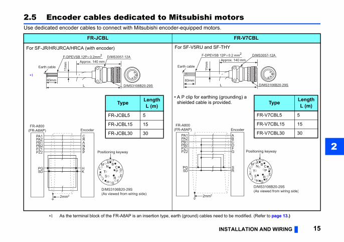
Type Length L (m)
FR-V7CBL5 5
FR-V7CBL15 15
FR-V7CBL30 30
unding) a ed.
INS
2.5 Encoder cables dedicated to Mitsubishi moUse dedicated encoder cables to connect with Mitsubishi encoder-equipped motors.
As the terminal block of the FR-A8AP is an insertion type, earth (ground) cables need to
FR-JCBL
For SF-JR/HR/JRCA/HRCA (with encoder) For SF-V5RU and SF-TH
Encoder
Positioning keywayPZ2PZ1PB2PB1PA2PA1
PGSD
PBNARC
HK
2mm2
A BC
D
EK
FGHJ
LM
S
N
R
PT
D/MS3106B20-29S(As viewed from wiring side)
FR-A800(FR-A8AP)
F-DPEVSB 12P 0.2mm2
Earth cableApprox. 140 mm
60mmL
D/MS3057-12A
D/MS3106B20-29S
11m
m
Type Length L (m)
FR-JCBL5 5
FR-JCBL15 15
FR-JCBL30 30
PZ2PZ1PB2PB1PA2PA1
SDPG
2mm2
FR-A800(FR-A8AP)
Earth cable
F-DPEVSB 12P
L
11m
m
60mm
App
• A P clip for earthing (groshielded cable is provid
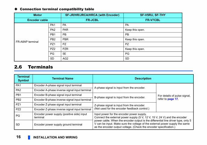
Connection terminal compatibility tableSF-V5RU, SF-THY
FR-V7CBL
open.
open.
open.
escription
ncoder.
For details of pulse signal, refer to page 17.ncoder.
ncoder.k control.)
r supply.y (5 V, 12 V, 15 V, 24 V) and the encoder utput is the differential line driver type, only 5 tage of the external power supply the same heck the encoder specification.)
16 INSTALLATION AND WIRING
2.6 Terminals
Motor SF-JR/HR/JRCA/HRCA (with Encoder)Encoder cable FR-JCBL
FR-A8AP terminal
PA1 PA PA
PA2 PAR Keep this
PB1 PB PB
PB2 PBR Keep this
PZ1 PZ PZ
PZ2 PZR Keep this
PG 5E PG
SD AG2 SD
Terminal Symbol Terminal Name D
PA1 Encoder A-phase signal input terminalA-phase signal is input from the e
PA2 Encoder A-phase inverse signal input terminal
PB1 Encoder B-phase signal input terminalB-phase signal is input from the e
PB2 Encoder B-phase inverse signal input terminal
PZ1 Encoder Z-phase signal input terminal Z-phase signal is input from the e(Not used for the encoder feedbacPZ2 Encoder Z-phase inverse signal input terminal
PG Encoder power supply (positive side) input terminal
Input power for the encoder poweConnect the external power supplpower cable. When the encoder oV can be input. Make sure the volas the encoder output voltage. (C
SD Encoder power supply ground terminal
PARAMETER SETTINGS 17
3
ETER SETTINGS
together, the encoder is shared between
volution). with a speed ratio of 1 to 1 without any
direction and the A and B phases
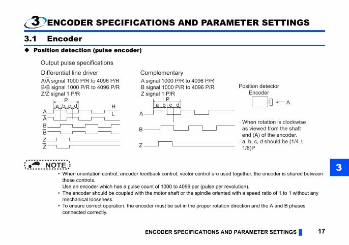
When rotation is clockwiseas viewed from the shaftend (A) of the encoder.a, b, c, d should be (1/41/8)P
A
Position detectorEncoder
ENCODER SPECIFICATIONS AND
3 ENCODER SPECIFICATIONS AND PARAM
3.1 Encoder Position detection (pulse encoder)
NOTE • When orientation control, encoder feedback control, vector control are used
these controls.Use an encoder which has a pulse count of 1000 to 4096 ppr (pulse per re
• The encoder should be coupled with the motor shaft or the spindle orientedmechanical looseness.
• To ensure correct operation, the encoder must be set in the proper rotationconnected correctly.
Pa b c d H
AABBZZ
L
A/A signal 1000 P/R to 4096 P/RB/B signal 1000 P/R to 4096 P/RZ/Z signal 1 P/R
A signal 1000 P/R to 4096 P/RB signal 1000 P/R to 4096 P/RZ signal 1 P/R
Differential line driver ComplementaryOutput pulse specifications
A
B
Z
a b c dP
V). When the encoder output is the power supply the same as the encoder
tor control, the power supply is shared
-control dedicated motors
differ, the protective function (E.ECT) may
coder for SF-V5RU, SF-THY
v
y
supply for encoder-3 V" or moreess
18 ENCODER SPECIFICATIONS AND PARAMETER SETTINGS
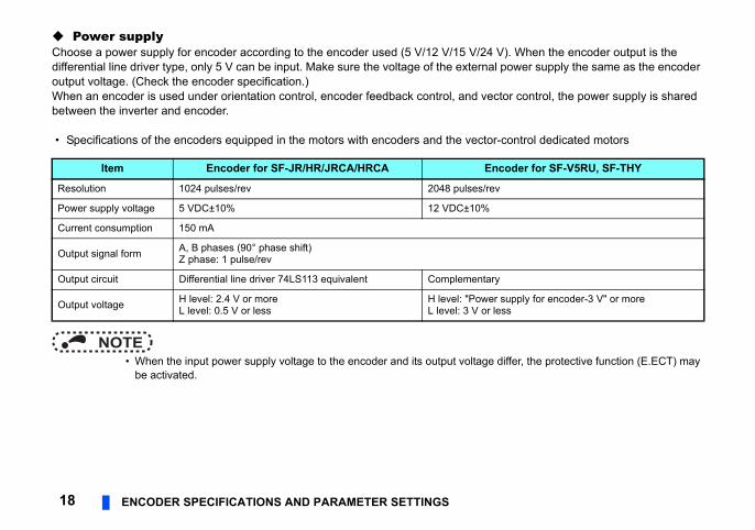
Power supplyChoose a power supply for encoder according to the encoder used (5 V/12 V/15 V/24 differential line driver type, only 5 V can be input. Make sure the voltage of the externaloutput voltage. (Check the encoder specification.)When an encoder is used under orientation control, encoder feedback control, and vecbetween the inverter and encoder.
• Specifications of the encoders equipped in the motors with encoders and the vector
NOTE • When the input power supply voltage to the encoder and its output voltage
be activated.
Item Encoder for SF-JR/HR/JRCA/HRCA En
Resolution 1024 pulses/rev 2048 pulses/re
Power supply voltage 5 VDC±10% 12 VDC±10%
Current consumption 150 mA
Output signal form A, B phases (90° phase shift)Z phase: 1 pulse/rev
Output circuit Differential line driver 74LS113 equivalent Complementar
Output voltage H level: 2.4 V or moreL level: 0.5 V or less
H level: "PowerL level: 3 V or l
PARAMETER SETTINGS 19
3
otor rotation will be unstable.
Description
otor for which coder) is clockwise
the shaft
Set for the operation at 120 Hz or less.
Set for the operation at a frequency higher than 120 Hz.
otor for which coder) is CW) viewed from
Set for the operation at 120 Hz or less.
Set for the operation at a frequency higher than 120 Hz.
ncoder pulses output.ulses before it is multiplied by 4.
CW
CCW
ENCODER SPECIFICATIONS AND
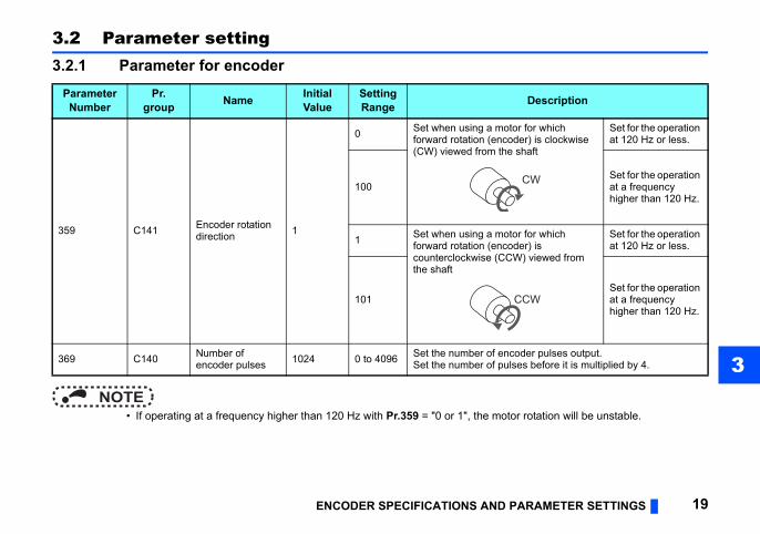
3.2 Parameter setting3.2.1 Parameter for encoder
NOTE • If operating at a frequency higher than 120 Hz with Pr.359 = "0 or 1", the m
ParameterNumber
Pr.group Name Initial
ValueSetting Range
359 C141 Encoder rotation direction 1
0 Set when using a mforward rotation (en(CW) viewed from
100
1 Set when using a mforward rotation (encounterclockwise (Cthe shaft
101
369 C140 Number of encoder pulses 1024 0 to 4096 Set the number of e
Set the number of p
ol Pr.369 Number of
encoder pulses
1024 (Initial value)
1024 (Initial value)
1024 (Initial value)
1024 (Initial value)
1024 (Initial value)
2048
2048
20 ENCODER SPECIFICATIONS AND PARAMETER SETTINGS
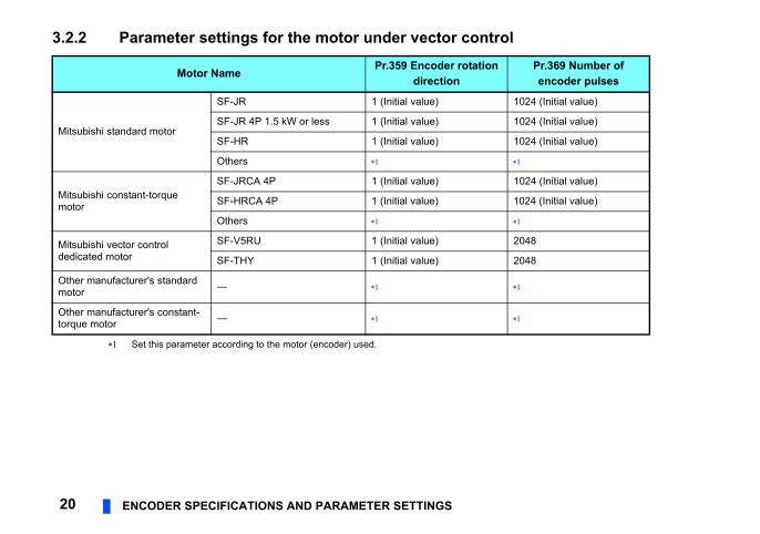
3.2.2 Parameter settings for the motor under vector contr
Set this parameter according to the motor (encoder) used.
Motor Name Pr.359 Encoder rotationdirection
Mitsubishi standard motor
SF-JR 1 (Initial value)
SF-JR 4P 1.5 kW or less 1 (Initial value)
SF-HR 1 (Initial value)
Others
Mitsubishi constant-torque motor
SF-JRCA 4P 1 (Initial value)
SF-HRCA 4P 1 (Initial value)
Others
Mitsubishi vector control dedicated motor
SF-V5RU 1 (Initial value)
SF-THY 1 (Initial value)
Other manufacturer's standard motor —
Other manufacturer's constant-torque motor —
ORIENTATION CONTROL 21
4
chine tool, etc. to allow a rotary shaft to
anual (Detailed) of the inverter.
∗2
∗5
∗7 ∗8
Differential
Terminatingresistor ON
OFF
Complementary
SF-V5RU
UVW
UVWE
G1
G2
A
Earth (Ground)2 W1 kΩ
∗6
BPA1FR-A8APPA2
PB1PB2
PZ1PZ2
PG
PGSD
SD
CD
FG
SR
IM
FAN
Encoder
nalal relay
∗11
ThermalrelayprotectorOH
SD
PC
Inverter
or complementary type (SF-V5RU)
12 VDC powersupply ∗9
(+) (-)
1haseowerupply
MCCB MC OCR
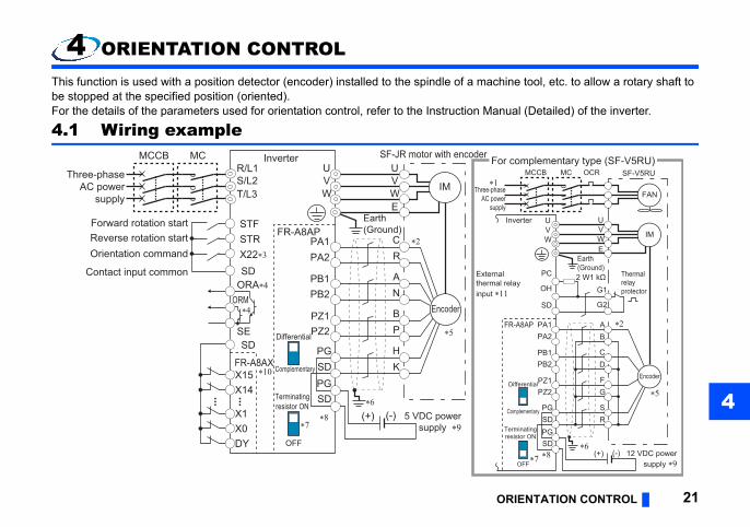
4 ORIENTATION CONTROLThis function is used with a position detector (encoder) installed to the spindle of a mabe stopped at the specified position (oriented).For the details of the parameters used for orientation control, refer to the Instruction M
4.1 Wiring example
Three-phaseAC power
supply
MCCBR/L1S/L2T/L3
DY
SF-JR motor with encoderUVW
UVWE
C
∗6
∗2
∗5
∗10
∗7∗8
X0X1
X14X15
RPA1
FR-A8AP
PA2
PB1PB2
PZ1PZ2
PG
PGSD
SD
Differential
Terminatingresistor ON
OFF
Complementary
AN
BP
HK
IM
Forward rotation startReverse rotation startOrientation command
Contact input common
STFSTR
SD
SD
X22∗3
Encoder
Earth (Ground)
Inverter
ORMORA∗4
SE
∗4
FR-A8AX
Extertherminput
F
5 VDC powersupply ∗9
(+) (-)
MC
∗Three-p
AC ps
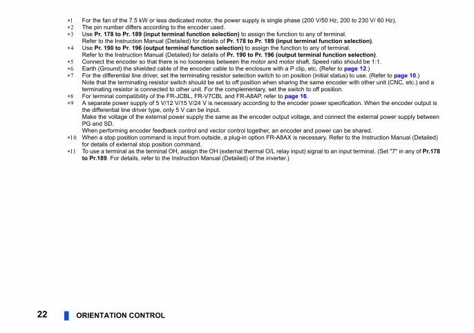
For the fan of the 7.5 kW or less dedicated motor, the power supply is single phase (200 V/50 Hz, 200 to 230 V/ 60 Hz).
y of terminal.al function selection).ny of terminal.
inal function selection).Speed ratio should be 1:1.tc. (Refer to page 12.) (initial status) to use. (Refer to page 10.)ame encoder with other unit (CNC, etc.) and a off position.
ower specification. When the encoder output is
and connect the external power supply between
power can be shared.ssary. Refer to the Instruction Manual (Detailed)
gnal to an input terminal. (Set "7" in any of Pr.178
22 ORIENTATION CONTROL
The pin number differs according to the encoder used. Use Pr. 178 to Pr. 189 (input terminal function selection) to assign the function to an
Refer to the Instruction Manual (Detailed) for details of Pr. 178 to Pr. 189 (input termin Use Pr. 190 to Pr. 196 (output terminal function selection) to assign the function to a
Refer to the Instruction Manual (Detailed) for details of Pr. 190 to Pr. 196 (output term Connect the encoder so that there is no looseness between the motor and motor shaft. Earth (Ground) the shielded cable of the encoder cable to the enclosure with a P clip, e For the differential line driver, set the terminating resistor selection switch to on position
Note that the terminating resistor switch should be set to off position when sharing the sterminating resistor is connected to other unit. For the complementary, set the switch to
For terminal compatibility of the FR-JCBL, FR-V7CBL and FR-A8AP, refer to page 16. A separate power supply of 5 V/12 V/15 V/24 V is necessary according to the encoder p
the differential line driver type, only 5 V can be input.Make the voltage of the external power supply the same as the encoder output voltage,PG and SD.When performing encoder feedback control and vector control together, an encoder and
When a stop position command is input from outside, a plug-in option FR-A8AX is necefor details of external stop position command.
To use a terminal as the terminal OH, assign the OH (external thermal O/L relay input) sito Pr.189. For details, refer to the Instruction Manual (Detailed) of the inverter.)
ORIENTATION CONTROL 23
4l function selection) and Pr.190 to Pr.196
tion
collector terminal.cted as the command signal entered.
cessary. Data is read only during the DY
before signal-off is retained.
Explanation
tion.t "22" in any of Pr. 178 to Pr. 189 to assign
within the in-position zone while the start
ut, assign the function by setting "27 of Pr. 190 to Pr. 196.
pleted within the in-position zone while the
ut, assign the function by setting "28 of Pr. 190 to Pr. 196.
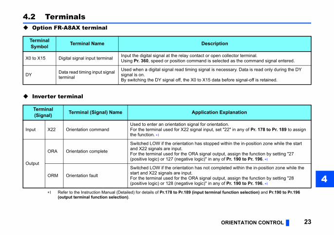
4.2 Terminals Option FR-A8AX terminal
Inverter terminal
Refer to the Instruction Manual (Detailed) for details of Pr.178 to Pr.189 (input termina(output terminal function selection).
TerminalSymbol Terminal Name Descrip
X0 to X15 Digital signal input terminal Input the digital signal at the relay contact or openUsing Pr. 360, speed or position command is sele
DY Data read timing input signal terminal
Used when a digital signal read timing signal is nesignal is on.By switching the DY signal off, the X0 to X15 data
Terminal(Signal) Terminal (Signal) Name Application
Input X22 Orientation commandUsed to enter an orientation signal for orientaFor the terminal used for X22 signal input, sethe function.
Output
ORA Orientation complete
Switched LOW if the orientation has stoppedand X22 signals are input.For the terminal used for the ORA signal outp(positive logic) or 127 (negative logic)" in any
ORM Orientation fault
Switched LOW if the orientation has not comstart and X22 signals are input.For the terminal used for the ORA signal outp(positive logic) or 128 (negative logic)" in any
taion, creep speed, position loop switching
er).tly or via a belt without any slip.
, DC injection brake start position setting, t, orientation in-position, position pulse
t servo lock function
op position command (open collector signal
24 ORIENTATION CONTROL
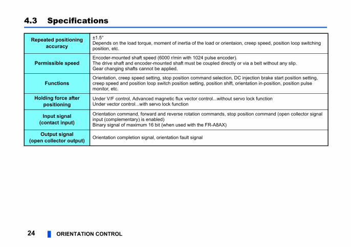
4.3 Specifications
Repeated positioning accuracy
±1.5°Depends on the load torque, moment of inertia of the load or orienposition, etc.
Permissible speedEncoder-mounted shaft speed (6000 r/min with 1024 pulse encodThe drive shaft and encoder-mounted shaft must be coupled direcGear changing shafts cannot be applied.
FunctionsOrientation, creep speed setting, stop position command selectioncreep speed and position loop switch position setting, position shifmonitor, etc.
Holding force after positioning
Under V/F control, Advanced magnetic flux vector control...withouUnder vector control...with servo lock function
Input signal (contact input)
Orientation command, forward and reverse rotation commands, stinput (complementary) is enabled)Binary signal of maximum 16 bit (when used with the FR-A8AX)
Output signal(open collector output) Orientation completion signal, orientation fault signal
ER FEEDBACK CONTROL 25
5
der V/F control or Advanced magnetic
ad variation by detecting the motor
ction Manual (Detailed) of the inverter.
JR motor with encoderUVWE
C ∗1
∗2
R
AN
HK
IM
Encoder
rthround)
5 VDC power supply ∗6
(+) (-)
ENCOD
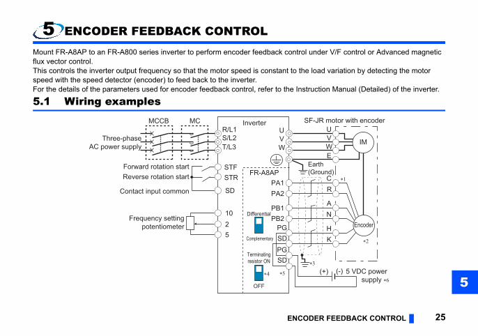
5 ENCODER FEEDBACK CONTROLMount FR-A8AP to an FR-A800 series inverter to perform encoder feedback control unflux vector control.This controls the inverter output frequency so that the motor speed is constant to the lospeed with the speed detector (encoder) to feed back to the inverter.For the details of the parameters used for encoder feedback control, refer to the Instru
5.1 Wiring examples
R/L1S/L2T/L3
SF-UVW
∗3
∗4 ∗5
PA1FR-A8AP
PA2
PB1PB2
PG
PGSD
SD
Differential
Terminatingresistor ON
OFF
Complementary
Forward rotation startReverse rotation start
Contact input common
Frequency settingpotentiometer
STFSTR
SD
1025
Ea(G
Inverter
Three-phaseAC power supply
MCCB MC
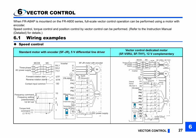
The pin number differs according to the encoder used.Speed ratio should be 1:1.tc. (Refer to page 12.)initial status) to use. (Refer to page 10) Note that der with other unit (CNC, etc) and a terminating
ower specification. When the encoder output is
and connect the external
102400 pulse/s or less encoder pulses)
26 ENCODER FEEDBACK CONTROL
Connect the encoder so that there is no looseness between the motor and motor shaft. Earth (Ground) the shielded cable of the encoder cable to the enclosure with a P clip, e For the differential line driver, set the terminating resistor selection switch to on position (
the terminating resistor switch should be set to off position when sharing the same encoresistor is connected to other unit.For the complementary, set the switch to off position.
For terminal compatibility of the FR-JCBL, FR-V7CBL and FR-A8AP, refer to page 16. A separate power supply of 5 V/12 V/15 V/24 V is necessary according to the encoder p
the differential line driver type, only 5 V can be input.Make the voltage of the external power supply the same as the encoder output voltage,power supply between PG and SD.To perform orientation control together, an encoder and power supply can be shared.
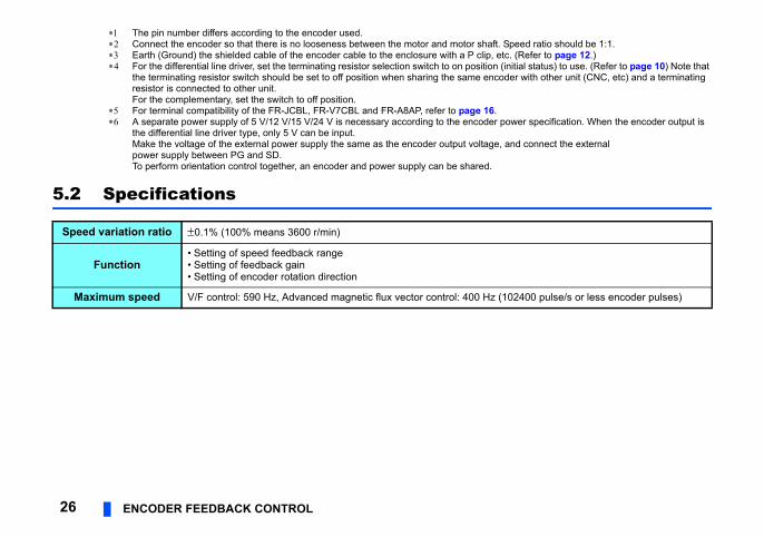
5.2 Specifications
Speed variation ratio 0.1% (100% means 3600 r/min)
Function• Setting of speed feedback range• Setting of feedback gain• Setting of encoder rotation direction
Maximum speed V/F control: 590 Hz, Advanced magnetic flux vector control: 400 Hz (
VECTOR CONTROL 276
can be performed using a motor with
(Refer to the Instruction Manual
ctor control dedicated motorU, SF-THY), 12 V complementary
*4 *6*3
PA1FR-A8AP
PA2
PB1PB2
PZ1PZ2
PG
PGSD
SD
*1
Differential
Terminatingresistor
ON
OFF
Complementary
SF-V5RU, SF-THY
UVW
U
ABC
VWE
G1G2
A
Earth(Ground)
*2
asewerpply
MCCB MC OCR
BPA1PA2
PB1PB2
PZ1PZ2
PG
PGSD
SD
CD
FG
SR
IM
FAN
Externalthermalrelay input *8
Thermal relayprotector
*7
OHSD
Inverter
PC2W1kΩ
12VDC power supply(+) (-) *5
Encoder
6 VECTOR CONTROLWhen FR-A8AP is mounterd on the FR-A800 series, full-scale vector control operationencoder.Speed control, torque control and position control by vector control can be performed. (Detailed) for details.)
6.1 Wiring examples Speed control
Standard motor with encoder (SF-JR), 5 V differential line driver Ve(SF-V5R
R/L1S/L2T/L3
SF-JR motor with encoderUVW
UVWE
C
∗3
∗1
∗2
∗4
∗6
RPA1
FR-A8AP
PA2
PB1PB2
PZ1PZ2
PG
PGSD
SD
Differential
Terminatingresistor ON
OFF
Complementary
A
N
BP
HK
IM
Forward rotation startReverse rotation start
Contact input common
STFSTR
SD
Encoder
Earth(Ground)
Inverter
10
22
3
1
Torque limitcommand
( 10 V)1
Frequency commandFrequency setting
potentiometer1/2 W1 kΩ 5
(+)(-) 5 VDC power supply(+) (-)
∗5
Three-phaseAC power supply
MCCB MC Three-phAC po
su
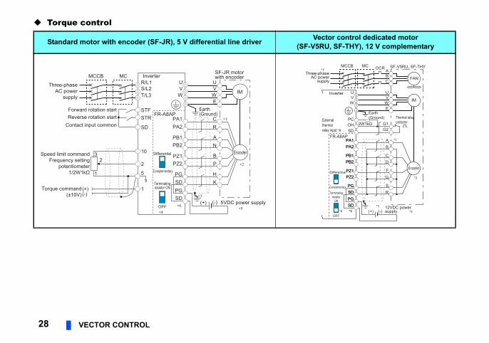
Torque control
ctor control dedicated motorU, SF-THY), 12 V complementary
*4 *6*3
PA1FR-A8AP
PA2
PB1PB2
PZ1PZ2
PG
PGSD
SD
*1
Differential
Terminatingresistor
ON
OFF
Complementary
SF-V5RU, SF-THY
UVW
U
ABC
VWE
G1G2
A
Earth(Ground)
*2
asewerpply
MCCB MC OCR
BPA1PA2
PB1PB2
PZ1PZ2
PG
PGSD
SD
CD
FG
SR
IM
FAN
Externalthermalrelay input *8
Thermal relayprotector
*7
OHSD
Inverter
PC2W1kΩ
12VDC power supply(+) (-) *5
Encoder
28 VECTOR CONTROL
Standard motor with encoder (SF-JR), 5 V differential line driver Ve(SF-V5R
R/L1S/L2T/L3
SF-JR motorwith encoder
UVW
UVWE
C
∗3
∗1
∗2
∗4∗6
RPA1
FR-A8AP
PA2
PB1PB2
PZ1PZ2
PG
PGSD
SD
Differential
Terminatingresistor ON
OFF
Complementary
AN
BP
HK
IM
Forward rotation startReverse rotation start
Contact input common
STFSTR
SD
Earth(Ground)
Inverter
5VDC power supply(+) (-)∗5
10
22
3
1
Torque command(±10V)
1
Speed limit commandFrequency setting
potentiometer1/2W1kΩ 5
(+)(-)
Three-phaseAC power
supply
MCCB MC
Encoder
Three-phAC po
su
VECTOR CONTROL 296
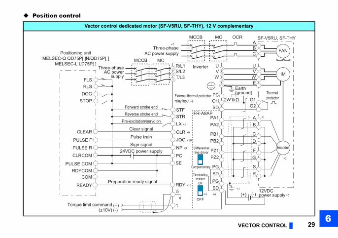
Position control
mplementary
∗3
∗1
SF-V5RU, SF-THY
U
ABC
VWE
G1G2
A
Earth(ground)
∗2
OCR
B
CD
FG
SR
IM
FAN
Thermalprotector2W1kΩ
12VDC power supply(+) (-) ∗5
Encoder
Vector control dedicated motor (SF-V5RU, SF-THY), 12 V co
Torque limit command(±10V)
1
5
(+)(-)
Three-phaseAC power
supply
MCCBR/L1S/L2T/L3
∗4 ∗6
PA1FR-A8AP
PA2
PB1PB2
PZ1PZ2
PG
PGSD
SD
Forward stroke endReverse stroke end
Pre-excitation/servo on
Clear signal
Pulse train
Sign signal
Preparation ready signal
STFSTRLX ∗9
CLR ∗9CLEAR
JOG ∗10
NP ∗9 Differentialline driver
Terminatingresistor
ON
OFF
UVW
Three-phaseAC power supply
MCCB MC
External thermal protectorrelay input ∗8
∗7
OHSD
Inverter
Positioning unitMELSEC-Q QD75P[ ]N/QD75P[ ]
MELSEC-L LD75P[ ]
PC
PULSE F
PULSE R
PULSE COM
CLRCOM
RDYCOM
READY
PC
RDY ∗11
SE
FLSRLS
DOGSTOP
COM
24VDC power supply
MC
Complementary
h or without the Z-phase being connected.Speed ratio must be 1:1.-clip. (Refer to page 12.)efer to page 10.)ower specification.
nd connect the external power supply across PG
red.
00 V/50 Hz, 200 to 230 V/60 Hz)gnal to an input terminal. (Set "7" in any of Pr.178
selection).ulse train input terminal becomes valid.
30 VECTOR CONTROL
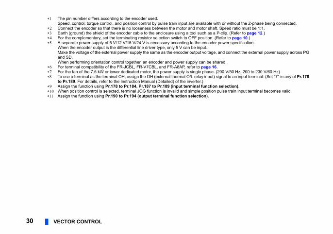
The pin number differs according to the encoder used.Speed, control, torque control, and position control by pulse train input are available wit
Connect the encoder so that there is no looseness between the motor and motor shaft. Earth (ground) the shield of the encoder cable to the enclosure using a tool such as a P For the complementary, set the terminating resistor selection switch to OFF position. (R A separate power supply of 5 V/12 V/15 V/24 V is necessary according to the encoder p
When the encoder output is the differential line driver type, only 5 V can be input.Make the voltage of the external power supply the same as the encoder output voltage, aand SD.When performing orientation control together, an encoder and power supply can be sha
For terminal compatibility of the FR-JCBL, FR-V7CBL, and FR-A8AP, refer to page 16. For the fan of the 7.5 kW or lower dedicated motor, the power supply is single phase. (2 To use a terminal as the terminal OH, assign the OH (external thermal O/L relay input) si
to Pr.189. For details, refer to the Instruction Manual (Detailed) of the inverter.) Assign the function using Pr.178 to Pr.184, Pr.187 to Pr.189 (input terminal function When position control is selected, terminal JOG function is invalid and simple position p Assign the function using Pr.190 to Pr.194 (output terminal function selection).
VECTOR CONTROL 316
)
Pr.369) 4
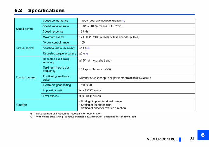
6.2 Specifications
Regeneration unit (option) is necessary for regeneration With online auto tuning (adaptive magnetic flux observer), dedicated motor, rated load
Speed control
Speed control range 1:1500 (both driving/regeneration )
Speed variation ratio ±0.01% (100% means 3000 r/min)
Speed response 130 Hz
Maximum speed 120 Hz (102400 pulse/s or less encoder pulses
Torque control
Torque control range 1:50
Absolute torque accuracy ±10%
Repeated torque accuracy ±5%
Position control
Repeated positioning accuracy ±1.5° (at motor shaft end)
Maximum input pulse frequency 100 kpps (Terminal JOG)
Positioning feedback pulse Number of encoder pulses per motor rotation (
Electronic gear setting 1/50 to 20
In-position width 0 to 32767 pulses
Error excess 0 to 400k pulses
Function• Setting of speed feedback range• Setting of feedback gain• Setting of encoder rotation direction

32
REVISIONS*The manual number is given on the bottom left of the back cover.
Print Date *Manual Number Revision
Aug. 2013 IB(NA)-0600505ENG-A First edition
Sep. 2014 IB(NA)-0600505ENG-B ModificationFerrule terminals commercially available
IB(NA)-0600505ENG-B

INVERTER
HEAD OFFICE: TOKYO BUILDING 2-7-3, MARUNOUCHI, CHIYODA-KU, TOKYO 100-8310, JAPAN
Printed in Japan Specifications subject to change without notice.IB(NA)-0600505ENG-B(1409) MEE