Embed Size (px)
Citation preview
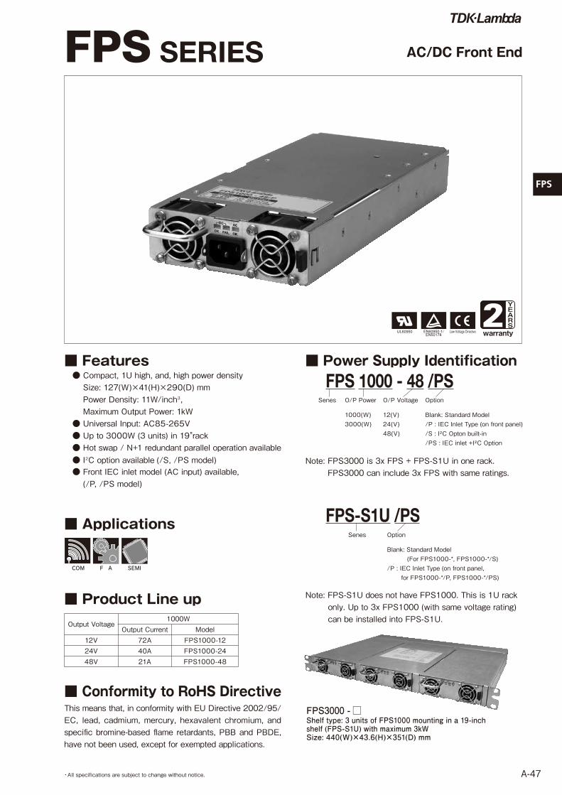
FPS
A-47・All specifications are subject to change without notice.
■ Features ● Compact, 1U high, and, high power density
Size: 127(W)×41(H)×290(D) mmPower Density: 11W/inch3,Maximum Output Power: 1kW
● Universal Input: AC85-265V ● Up to 3000W (3 units) in 19"rack ● Hot swap / N+1 redundant parallel operation available ● I2C option available (/S, /PS model) ● Front IEC inlet model (AC input) available, (/P, /PS model)
AC/DC Front End
■ Power Supply Identification FPS 1000 - 48 /PS
Senes O/P Power O/P Voltage
YEARS
warranty2
■ Product Line upOutput Voltage
1000WOutput Current Model
12V 72A FPS1000-1224V 40A FPS1000-2448V 21A FPS1000-48
FPS3000 - □Shelf type: 3 units of FPS1000 mounting in a 19-inch shelf (FPS-S1U) with maximum 3kWSize: 440(W)×43.6(H)×351(D) mm
■ Applications
医 療 計 測 F A 半導体 その他
その他ks
コンピュータ 通 信 F A 半導体
その他ph
pf-a
hk-a
hws
alpha
dlp
fps
フォーマット
コンピュータ 通 信 F A 半導体
その他
コンピュータ 通 信 医 療 計 測 F A 半導体
その他
コンピュータ 通 信 医 療 計 測 F A 半導体
その他
コンピュータ 通 信 医 療 計 測 F A 半導体
その他
コンピュータ 通 信 医 療 計 測 F A 半導体
その他
医 療 計 測 F A 半導体 その他
その他ks
コンピュータ 通 信 F A 半導体
その他ph
pf-a
hk-a
hws
alpha
dlp
fps
フォーマット
コンピュータ 通 信 F A 半導体
その他
コンピュータ 通 信 医 療 計 測 F A 半導体
その他
コンピュータ 通 信 医 療 計 測 F A 半導体
その他
コンピュータ 通 信 医 療 計 測 F A 半導体
その他
コンピュータ 通 信 医 療 計 測 F A 半導体
その他
Option
1000(W)3000(W)
12(V)24(V)48(V)
Blank: Standard Model/P : IEC Inlet Type (on front panel)/S : I²C Opton built-in/PS : IEC inlet +I²C Option
FPS-S1U /PSSenes Option
Blank: Standard Model (For FPS1000-*, FPS1000-*/S)/P : IEC Inlet Type (on front panel, for FPS1000-*/P, FPS1000-*/PS)
Note: FPS3000 is 3x FPS + FPS-S1U in one rack. FPS3000 can include 3x FPS with same ratings.
This means that, in conformity with EU Directive 2002/95/ EC, lead, cadmium, mercury, hexavalent chromium, and specific bromine-based flame retardants, PBB and PBDE, have not been used, except for exempted applications.
■ Conformity to RoHS Directive
Note: FPS-S1U does not have FPS1000. This is 1U rack only. Up to 3x FPS1000 (with same voltage rating) can be installed into FPS-S1U.
FPS SERIES
FPS
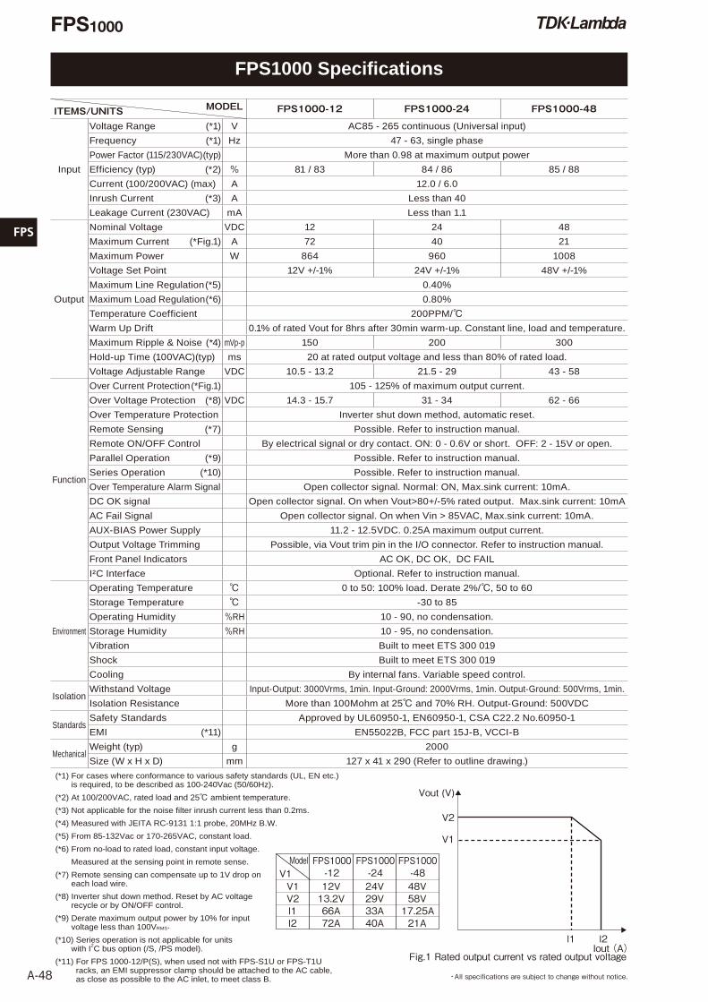
A-48Fig.1 Rated output current vs rated output voltage
V2
Vout (V)
V1
l1 l2
FPS1000-24
V1V1Model
24V V2 29V l1 33A l2 40A
FPS1000-1212V13.2V66A72A
48V58V17.25A21A
FPS1000-48
Iout (A)
・All specifications are subject to change without notice.
ITEMS/UNITS� MODEL FPS1000-12 FPS1000-24 FPS1000-48
Input
Voltage Range (*1) V AC85 - 265 continuous (Universal input)
Frequency (*1) Hz 47 - 63, single phase
Power Factor (115/230VAC) (typ) More than 0.98 at maximum output power
Efficiency (typ) (*2) % 81 / 83 84 / 86 85 / 88
Current (100/200VAC) (max) A 12.0 / 6.0
Inrush Current (*3) A Less than 40
Leakage Current (230VAC) mA Less than 1.1
Output
Nominal Voltage VDC 12 24 48
Maximum Current (*Fig.1) A 72 40 21
Maximum Power W 864 960 1008
Voltage Set Point 12V +/-1% 24V +/-1% 48V +/-1%
Maximum Line Regulation (*5) 0.40%
Maximum Load Regulation (*6) 0.80%
Temperature Coefficient 200PPM/℃Warm Up Drift 0.1% of rated Vout for 8hrs after 30min warm-up. Constant line, load and temperature.
Maximum Ripple & Noise (*4) mVp-p 150 200 300
Hold-up Time (100VAC)(typ) ms 20 at rated output voltage and less than 80% of rated load.
Voltage Adjustable Range VDC 10.5 - 13.2 21.5 - 29 43 - 58
Function
Over Current Protection (*Fig.1) 105 - 125% of maximum output current.
Over Voltage Protection (*8) VDC 14.3 - 15.7 31 - 34 62 - 66
Over Temperature Protection Inverter shut down method, automatic reset.
Remote Sensing (*7) Possible. Refer to instruction manual.
Remote ON/OFF Control By electrical signal or dry contact. ON: 0 - 0.6V or short. OFF: 2 - 15V or open.
Parallel Operation (*9) Possible. Refer to instruction manual.
Series Operation (*10) Possible. Refer to instruction manual.
Over Temperature Alarm Signal Open collector signal. Normal: ON, Max.sink current: 10mA.
DC OK signal Open collector signal. On when Vout>80+/-5% rated output. Max.sink current: 10mA
AC Fail Signal Open collector signal. On when Vin > 85VAC, Max.sink current: 10mA.
AUX-BIAS Power Supply 11.2 - 12.5VDC. 0.25A maximum output current.
Output Voltage Trimming Possible, via Vout trim pin in the I/O connector. Refer to instruction manual.
Front Panel Indicators AC OK, DC OK, DC FAIL
I²C Interface Optional. Refer to instruction manual.
Environment
Operating Temperature ℃ 0 to 50: 100% load. Derate 2%/℃, 50 to 60
Storage Temperature ℃ -30 to 85
Operating Humidity %RH 10 - 90, no condensation.
Storage Humidity %RH 10 - 95, no condensation.
Vibration Built to meet ETS 300 019
Shock Built to meet ETS 300 019
Cooling By internal fans. Variable speed control.
IsolationWithstand Voltage Input-Output: 3000Vrms, 1min. Input-Ground: 2000Vrms, 1min. Output-Ground: 500Vrms, 1min.
Isolation Resistance More than 100Mohm at 25℃ and 70% RH. Output-Ground: 500VDC
StandardsSafety Standards Approved by UL60950-1, EN60950-1, CSA C22.2 No.60950-1
EMI (*11) EN55022B, FCC part 15J-B, VCCI-B
MechanicalWeight (typ) g 2000
Size (W x H x D) mm 127 x 41 x 290 (Refer to outline drawing.)
(*1) For cases where conformance to various safety standards (UL, EN etc.) is required, to be described as 100-240Vac (50/60Hz).
(*2) At 100/200VAC, rated load and 25℃ ambient temperature.
(*3) Not applicable for the noise filter inrush current less than 0.2ms.
(*4) Measured with JEITA RC-9131 1:1 probe, 20MHz B.W.
(*5) From 85-132Vac or 170-265VAC, constant load.
(*6) From no-load to rated load, constant input voltage.
Measured at the sensing point in remote sense.
(*7) Remote sensing can compensate up to 1V drop on each load wire.
(*8) Inverter shut down method. Reset by AC voltage recycle or by ON/OFF control.
(*9) Derate maximum output power by 10% for input voltage less than 100VRMS.
(*10) Series operation is not applicable for units with I2C bus option (/S, /PS model).
(*11) For FPS 1000-12/P(S), when used not with FPS-S1U or FPS-T1U racks, an EMI suppressor clamp should be attached to the AC cable, as close as possible to the AC inlet, to meet class B.
FPS1000 Specifications
FPS1000
FPS
A-49・All specifications are subject to change without notice.
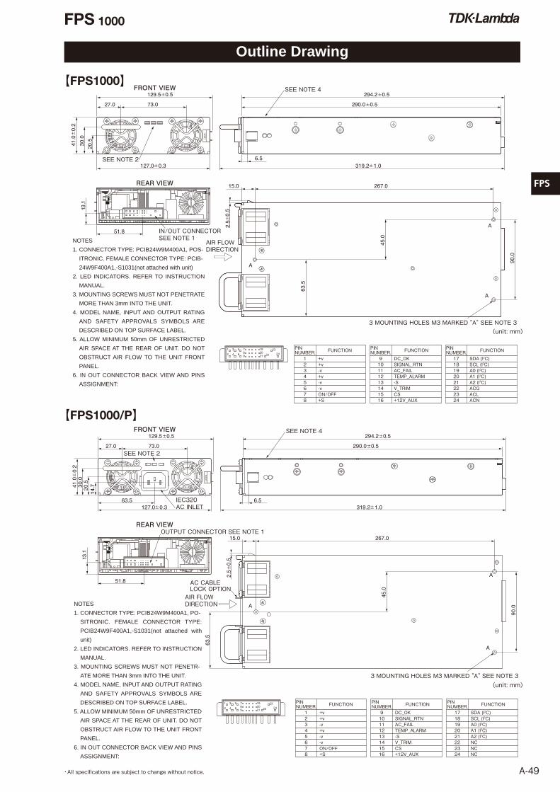
【FPS1000/P】
REAR VIEW
FRONT VIEW
AIR FLOW DIRECTION
SEE NOTE 2
OUTPUT CONNECTOR SEE NOTE 1
AC CABLE LOCK OPTION
IEC320 AC INLET
1
2
3
4
5
6
789
192021 22
2324
SEE NOTE 4
3 MOUNTING HOLES M3 MARKED "A" SEE NOTE 3
FUNCTION FUNCTION
DC_OKSIGNAL_RTNAC_FAILTEMP_ALARM-SV_TRIMCS+12V_AUX
PINNUMBER.
PINNUMBER.
+v+v-v+v-v-vON/OFF+S
1 2 3 4 5 6 7 8
9 10 11 12 13 14 15 16
FUNCTION
SDA (I2C)SCL (I2C)A0 (I2C)A1 (I2C)A2 (I2C)NCNCNC
PINNUMBER. 17 18 19 20 21 22 23 24
NOTES
1. CONNECTOR TYPE: PCIB24W9M400A1, PO-
SITRONIC. FEMALE CONNECTOR TYPE:
PCIB24W9F400A1,-S1031(not attached with
unit)
2. LED INDICATORS. REFER TO INSTRUCTION
MANUAL.
3. MOUNTING SCREWS MUST NOT PENETR-
ATE MORE THAN 3mm INTO THE UNIT.
4. MODEL NAME, INPUT AND OUTPUT RATING
AND SAFETY APPROVALS SYMBOLS ARE
DESCRIBED ON TOP SURFACE LABEL.
5. ALLOW MINIMUM 50mm OF UNRESTRICTED
AIR SPACE AT THE REAR OF UNIT. DO NOT
OBSTRUCT AIR FLOW TO THE UNIT FRONT
PANEL.
6. IN OUT CONNECTOR BACK VIEW AND PINS
ASSIGNMENT:
AIR FLOWDIRECTION
IN/OUT CONNECTORSEE NOTE 1
3 MOUNTING HOLES M3 MARKED "A" SEE NOTE 3
SEE NOTE 2
1
2
3
4
5
6
789
192021 22
2324
FUNCTION FUNCTION
DC_OKSIGNAL_RTNAC_FAILTEMP_ALARM-SV_TRIMCS+12V_AUX
PINNUMBER.
PINNUMBER.
+v+v-v+v-v-vON/OFF+S
1 2 3 4 5 6 7 8
9 10 11 12 13 14 15 16
FUNCTION
SDA (I2C)SCL (I2C)A0 (I2C)A1 (I2C)A2 (I2C)ACGACLACN
PINNUMBER. 17 18 19 20 21 22 23 24
NOTES
1. CONNECTOR TYPE: PCIB24W9M400A1, POS-
ITRONIC. FEMALE CONNECTOR TYPE: PCIB-
24W9F400A1,-S1031(not attached with unit)
2. LED INDICATORS. REFER TO INSTRUCTION
MANUAL.
3. MOUNTING SCREWS MUST NOT PENETRATE
MORE THAN 3mm INTO THE UNIT.
4. MODEL NAME, INPUT AND OUTPUT RATING
AND SAFETY APPROVALS SYMBOLS ARE DESCRIBED ON TOP SURFACE LABEL.
5. ALLOW MINIMUM 50mm OF UNRESTRICTED
AIR SPACE AT THE REAR OF UNIT. DO NOT
OBSTRUCT AIR FLOW TO THE UNIT FRONT
PANEL.
6. IN OUT CONNECTOR BACK VIEW AND PINS
ASSIGNMENT:
REAR VIEW
FRONT VIEW SEE NOTE 4
(unit: mm)
(unit: mm)
【FPS1000】
Outline Drawing
FPS 1000
FPS
A-50 ・All specifications are subject to change without notice.
ITEMS/UNITS� MODEL FPS-S1U
Input
Voltage Range (*2) V AC85 - 265 continuous (Universal input)
Frequency (*2) Hz 47 - 63, Single phase
Current (100/200VAC)(max) A 12.0 / 6.0 for each FPS1000 unit installed
Output Maximum Power (*1) W 3000
Function
Remote Sensing (*3) Possible.
Remote ON/OFF Control Separate control for each FPS1000 unit, by electrical signal or dry contact.
On: 0 - 0.6V or short. OFF: 2 - 15V or open.
Parallel Operation (*6) Possible.
Series Operation (*4) Possible. Up to 2 racks of the same voltage and current rating.
Over Temperature Alarm
Signal
Separate control for each FPS1000 unit, open collector signal.
Normal: ON, max.sink current: 10mA
DC OK Signal Separate control for each FPS1000 unit, open collector signal.
On when Vout>80%+/-5% max.sink current: 10mA
AC Fail Signal Separate control for each FPS1000 unit, open collector signal.
On when Vin > 85VAC, max.sink current: 10mA.
AUX-BIAS Power Supply 11.2 - 12.5VDC. Maximum output current: 0.25A x Number of installed FPS1000 units.
Output Voltage Trimming Possible. Refer to instruction manual.
AC Input Connector FPS-S1U: IEC inlet for each power supply module. FPS-S1U/P: None
Output Terminals Bus-bars. Refer to outline drawing.
Number of Power Supply Modules (*5) Maximum 3 FPS1000 modules of the same output voltage rating.
Environment
Operating Temperature ℃ 0 to 50: 100% load. Derate 2%/℃, 50 to 60.
Storage Temperature ℃ -30 to 85
Operating Humidity %RH 10 - 90, no condensation.
Storage Humidity %RH 10 - 95, no condensation.
Vibration Built to meet ETS 300 019
Shock Built to meet ETS 300 019
IsolationWithstand Voltage Input-Output: 3000Vrms, 1min. Input-Ground: 2000Vrms, 1min. Output-Ground: 500Vrms, 1min.
Isolation Resistance More than 100MΩ at 25℃ and 70% RH. Output-Ground: 500VDC
Standards Safety Standards UL60950-1, EN60950-1, CSA C22.2 No.60950-1
MechanicalWeight (typ) g 3700
Size (W x H x D) mm 440 x 44 x 351 (Refer to outline drawing.)
(*1) For input voltage lower than 100VAC, maximum output power is 2700W.
(*2) For cases where conformance to various safety standards (UL, EN etc.) is required, to be described as 100-240VAC (50/60Hz).
(*3) Remote sensing can compensate up to 1V drop on each load wire.
(*4) Not applicable for units with I2C bus option.
(*5) The output of all the FPS1000 modules are connected in parallel in the rack.
(*6) Up to 3 racks with max.8 FPS1000 units of the same voltage and current rating.
FPS-S1U Specifications
FPS-S1U
FPS
A-51・All specifications are subject to change without notice.
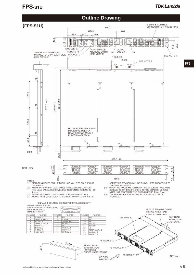
MODULE "A"MODULE "B"MODULE "C"
I2C INTERFACE ADDRESS SWITCH (SEE NOTE 3)
SEE NOTE 2.
SEE NOTE 1.
OUTPUT BUS BAR
SIGNAL & CONTROL CONNECTOR D-TYPE 25 PINS
SIDE MOUNTING HOLES MARKED "D" 3 ON EACH SIDE (SEE NOTE 5.)
HOLES FOR BLANK PANEL MOUNTING: USE FLAT HEAD SCREWS M3x6- 6 PLACES MARKED "A"
BLANK PANEL INFORMATION: (OPTIONAL) ORDER NAME: FPS-BP
1
1425
13
PIN NUMBER. FUNCTION 1 V_TRIM_B 2 TEMP_ALARM_B 3 DC_OK_B 4 TEMP_ALARM_A 5 ON/OFF_A 6 DC_OK_A 7 V_TRIM_A 8 +12V_AUX
CONNECTOR DESCRIPTION: D-TYPE RIGHT ANGLE, 25 POSITIONS, FRONT METAL SHELL, AMP P/N: 747846-4
SIGNALS & CONTROL CONNECTOR PINS ASSIGNMENT
PIN NUMBER. FUNCTION 9 CS 10 V_TRIM_C 11 SIGNAL_RTN 12 DC_OK_C 13 +S 14 AC_FAIL_B 15 ON/OFF_B 16 AC_FAIL_A
PIN NUMBER. FUNCTION 17 NC 18 NC 19 NC 20 SCL(l2C) 21 SDA(l2C) 22 -S 23 TEMP_ALARM_C 24 AC_FAIL_C 25 ON/OFF_C
41.0
127.0
NOTES(*1) MOUNTING HOLES FOR 19" RACK, USE M6x12 TO FIX THE UNIT
TO A RACK. (*2) M6x16 SCREWS FOR LOAD WIRES FIXING, USE M6 LUG FOR
THE LOAD WIRES, RECOMMENDED TIGHTENING TORQUE 42 - 56 Kgf.cm
(*3) REFER TO INSTRUCTION MANUAL FOR SETTING DETAILS.(*4) MODEL NAME , VOLTAGE AND CURRENT RATING AND SAFETY
APPROVALS SYMBOLS WILL BE SHOWN HERE ACCORDING TO THE SPECIFICATIONS.
(*5) MOUNTING HOLES M5 FOR MOUNTING BRACKETS . USE M5x8 SCREWS TO FIX THE BRACKETS TO THE CHASSIS. SCREWS MUST NOT PENETRATE THE CHASSIS MORE THAN 6 mm.
(*6) THE FPS-S1U RACK IS SHOWN WITH 3 FPS1000 UNITS INSTALLED.
0.4
0.0
【FPS-S1U】
SEE NOTE 4 FLAT HEAD SCREW M3x6 -2 PLACES-
PS MODULE "A"
OUTPUT TERMINAL COVER. INSTALL AFTER LOAD CABELS CONNECTION.
PS MODULE "B"
PS MODULE "C"AIR FLOW DIRECTION
UNIT : mm
UNIT : mm
Outline Drawing
FPS-S1U
FPS
A-52 ・All specifications are subject to change without notice.
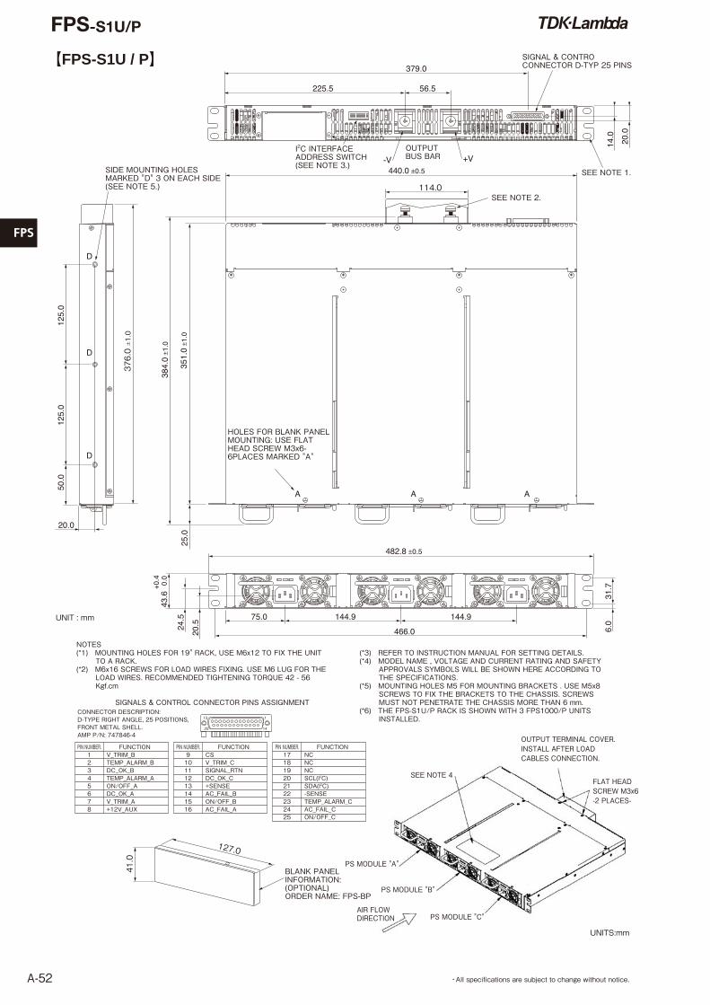
SIGNAL & CONTROCONNECTOR D-TYP 25 PINS
SEE NOTE 2.
SEE NOTE 1.
OUTPUTBUS BAR
I2C INTERFACEADDRESS SWITCH(SEE NOTE 3.)SIDE MOUNTING HOLES
MARKED "D" 3 ON EACH SIDE(SEE NOTE 5.)
HOLES FOR BLANK PANELMOUNTING: USE FLATHEAD SCREW M3x6-6PLACES MARKED "A"
1
1425
13
PIN NUMBER. FUNCTION 1 V_TRIM_B 2 TEMP_ALARM_B 3 DC_OK_B 4 TEMP_ALARM_A 5 ON/OFF_A 6 DC_OK_A 7 V_TRIM_A 8 +12V_AUX
CONNECTOR DESCRIPTION:D-TYPE RIGHT ANGLE, 25 POSITIONS,FRONT METAL SHELL.AMP P/N: 747846-4
SIGNALS & CONTROL CONNECTOR PINS ASSIGNMENT
PIN NUMBER. FUNCTION 9 CS 10 V_TRIM_C 11 SIGNAL_RTN 12 DC_OK_C 13 +SENSE 14 AC_FAIL_B 15 ON/OFF_B 16 AC_FAIL_A
PIN NUMBER. FUNCTION 17 NC 18 NC 19 NC 20 SCL(I2C) 21 SDA(I2C) 22 -SENSE 23 TEMP_ALARM_C 24 AC_FAIL_C 25 ON/OFF_C
BLANK PANELINFORMATION:(OPTIONAL)ORDER NAME: FPS-BP
41.0
127.0
NOTES(*1) MOUNTING HOLES FOR 19" RACK, USE M6x12 TO FIX THE UNIT
TO A RACK. (*2) M6x16 SCREWS FOR LOAD WIRES FIXING. USE M6 LUG FOR THE
LOAD WIRES. RECOMMENDED TIGHTENING TORQUE 42 - 56 Kgf.cm
(*3) REFER TO INSTRUCTION MANUAL FOR SETTING DETAILS.(*4) MODEL NAME , VOLTAGE AND CURRENT RATING AND SAFETY
APPROVALS SYMBOLS WILL BE SHOWN HERE ACCORDING TO THE SPECIFICATIONS.
(*5) MOUNTING HOLES M5 FOR MOUNTING BRACKETS . USE M5x8 SCREWS TO FIX THE BRACKETS TO THE CHASSIS. SCREWS MUST NOT PENETRATE THE CHASSIS MORE THAN 6 mm.
(*6) THE FPS-S1U/P RACK IS SHOWN WITH 3 FPS1000/P UNITS INSTALLED.
【FPS-S1U / P】
AIR FLOW DIRECTION
SEE NOTE 4
PS MODULE "A"
PS MODULE "B"
PS MODULE "C"
FLAT HEADSCREW M3x6-2 PLACES-
OUTPUT TERMINAL COVER. INSTALL AFTER LOADCABLES CONNECTION.
UNIT : mm
UNITS:mm
FPS-S1U/P