Embed Size (px)
Citation preview
International Journal of Science and Research (IJSR) ISSN (Online): 2319-7064
Index Copernicus Value (2013): 6.14 | Impact Factor (2013): 4.438
Volume 4 Issue 7, July 2015
www.ijsr.net Licensed Under Creative Commons Attribution CC BY
FPGA Implementation of SRRC Filter for WCDMA
Systems
K. Pavan Kumar1, Sri T. Thammi Reddy
2
1Student of M.Tech in VLSI & EMBEDDED Systems, Electronics and Communication Engineering, GPREC (Autonomous),
Kurnool,JNTU-A, Andhra Pradesh, India
2Associate Professor of Electronics and Communication Engineering, GPREC(Autonomous), Kurnool, JNTU-A, Andhra Pradesh, India
Abstract: This paper presents the FPGA implementation of Square root raised cosine filter for pulse shaping used in WCDMA
systems. Square root raised cosine filter is a FIR filter. Square root raised cosine filters are used in both transmitter and receiver for
matching filter purpose. Mainly square root raised cosine filter is used for pulse shaping so that it reduces the required system
bandwidth and also reduces inter symbol interference. SRRC filter also designed to maintain the power level in db’s . SRRC filter is
designed by five levels of adders with a roll off factor 0.2 .Shifting and add method is used for designing of SRRC filter.
Keywords: SRRC filter, FIR filter, Inter symbol interference, Pulse shaping, Roll off factor, WCDMA systems.
Figure 1: Block diagram of WCDMA Systems
1. Introduction
As digital technology ramps up this century, an ever-
increasing number of RF applications will involve the
transmission of digital data from one point to another. The
general scheme is to convert the data into a suitable base
band signal that is then modulated onto an RF carrier i.e
analog information is converted into digital form as an
ordered set of logical 1‟s and 0‟s (bits). Before delving into
the details of pulse shaping, it is important to understand that
pulses are sent by the transmitter and ultimately detected by
the receiver in any data transmission system. At the receiver,
the goal is to sample the received signal at an optimal point
in the pulse interval to maximize the probability of an
accurate binary decision. This implies that the fundamental
shapes of the pulses be such that they do not interfere with
one another at the optimal sampling point[1].
The unbounded frequency response of the rectangular pulse
renders it unsuitable for modern transmission systems. This
is where pulse shaping filters come into play. If the
rectangular pulse is not the best choice for band-limited data
transmission, then what pulse shape will limit bandwidth,
decay quickly, and provide zero crossings at the pulse
sampling times? The raised cosine pulse and root raised
cosine pulse, which is used in a wide variety of modern data
transmission systems.
Pulse shaping is a spectral processing technique by which
fractional out of band power is reduced for low cost,
reliable, power and spectrally efficient mobile radio
communication systems. It is clear that the pulse shaping
filter not only reduces inter symbol interference (ISI), but it
also reduces adjacent channel interference. To satisfy the
ever increasing demands for higher data rates as well as to
allow more users to simultaneously access the network,
interest has peaked in what has come to be known as
wideband code division multiple access (WCDMA) [2]. The
basic characteristics of WCDMA waveforms that make them
attractive for high data rate transmissions are their
advantages over other wireless systems. WCDMA is
considered to be wideband technologies based on the direct
Paper ID: 26071501 2581
International Journal of Science and Research (IJSR) ISSN (Online): 2319-7064
Index Copernicus Value (2013): 6.14 | Impact Factor (2013): 4.438
Volume 4 Issue 7, July 2015
www.ijsr.net Licensed Under Creative Commons Attribution CC BY
sequence spread spectrum transmission scheme, where user
information bits are spread over a wide bandwidth by
multiplying the user data with quasi-random bits called chips
derived from CDMA spreading codes. In order to support
very high bit rates (upto 2 Mbps), the use of a variable
spreading factor and multicode connection is supported.
Low complexity implementation method focuses on the
implementation of high order square root raised cosine fir
filter which is widely used in time domain band limited
communication systems as the digital baseband pulse-
shaping filter [3].
The design of series of square-root-raised-cosine (SRRC)
FIR filter according to the local search algorithm. The
simulation results of a baseband system show that two 13-
tap SRRC FIR filters with a roll-off factor 0.6 only
introduced about 6% peak distortion in the eye pattern. Bit-
level pipeline architecture was used to realize the high
sampling rate FIR filter [4].
A recursive method for designing the SRRC FIR filters
using a pair of matched SRRC filters in the transmitter and
the receiver in a band limited digital communication system
can theoretically achieve zero ISI. In reality, such pair of
SRRC filters does not exist. The ISI can be only reduced to
some level when both SRRC filters are approximately
implemented [5].
2. DSSS Representation
Spread spectrum is a modulation method applied to digitally
modulated signals that increases the transmit signal
bandwidth to a value much larger than is needed to transmit
the underlying information bits. Transmitted signal occupies
a bandwidth much larger than the BW of the message signal.
It hides a signal below the noise floor .So, it is very hard to
detect. Spectrum Provides multipath (ISI) rejection. It allows
many users to share the same bandwidth.
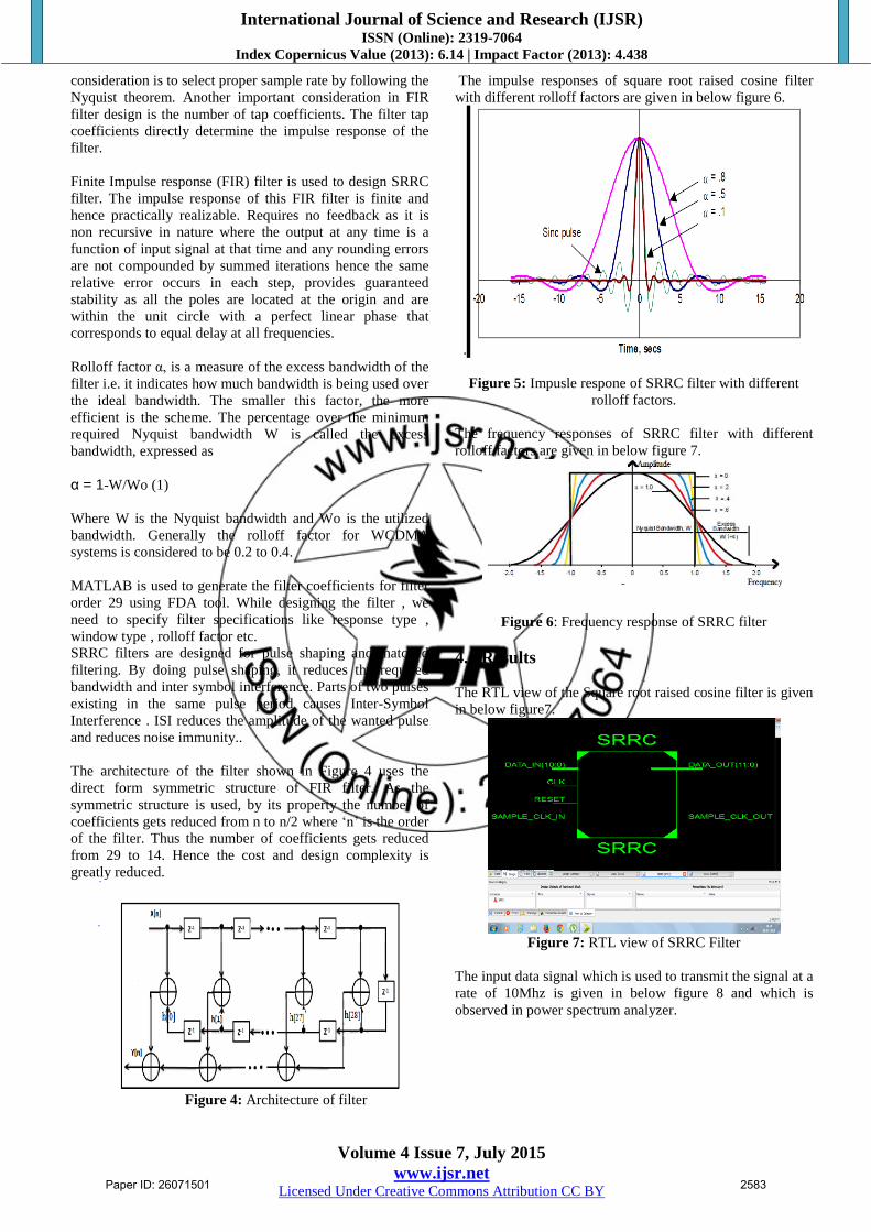
The direct spread spectrum modulation is done using a
spreading code, which is independent of the data in the
signal. Dispreading at the receiver is done by correlating the
received signal with a synchronized copy of the spreading
code. Direct spread sequence spectrum representation is
given in below figure 2.
Figure 2: DSSS Representation
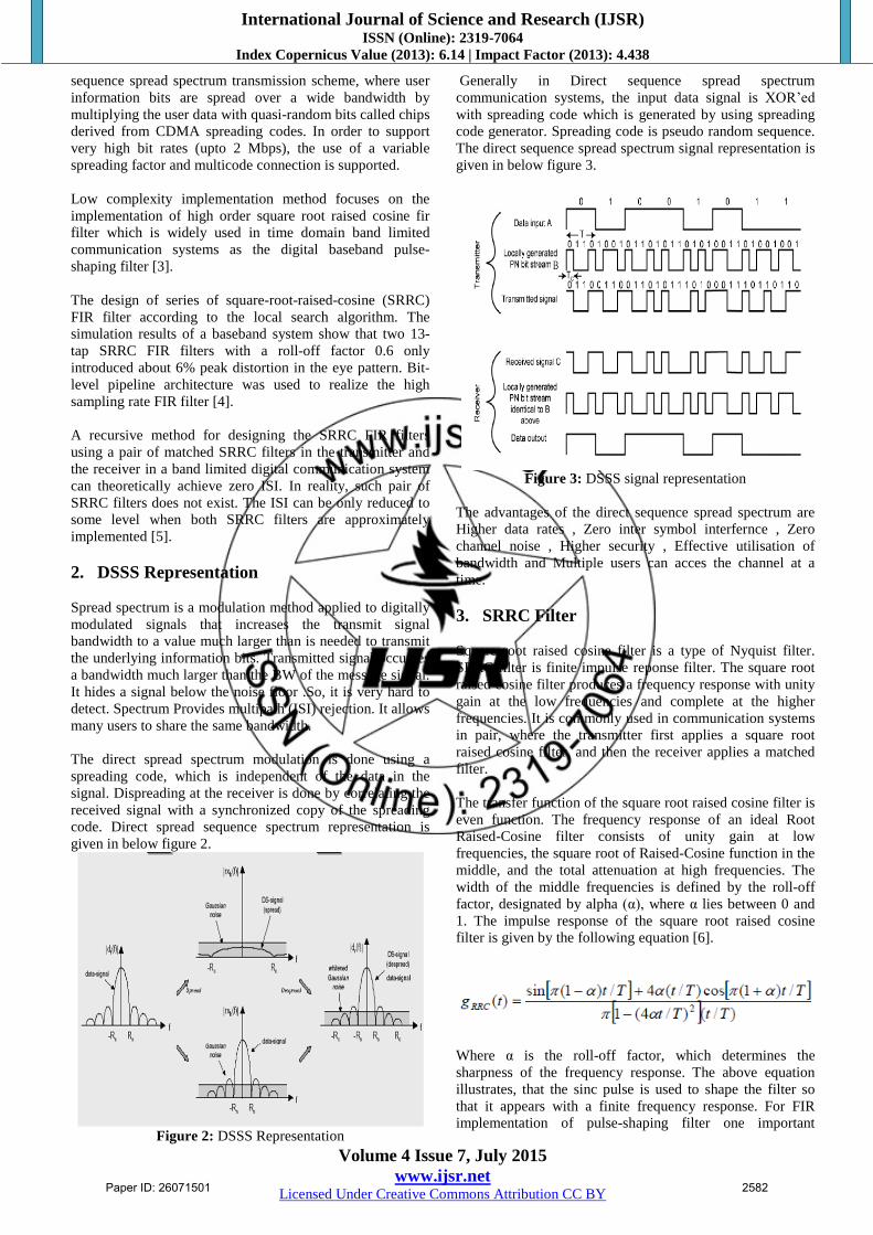
Generally in Direct sequence spread spectrum
communication systems, the input data signal is XOR‟ed
with spreading code which is generated by using spreading
code generator. Spreading code is pseudo random sequence.
The direct sequence spread spectrum signal representation is
given in below figure 3.
Figure 3: DSSS signal representation
The advantages of the direct sequence spread spectrum are
Higher data rates , Zero inter symbol interfernce , Zero
channel noise , Higher security , Effective utilisation of
bandwidth and Multiple users can acces the channel at a
time.
3. SRRC Filter
Square root raised cosine filter is a type of Nyquist filter.
SRRC filter is finite impulse reponse filter. The square root
raised cosine filter produces a frequency response with unity
gain at the low frequencies and complete at the higher
frequencies. It is commonly used in communication systems
in pair, where the transmitter first applies a square root
raised cosine filter, and then the receiver applies a matched
filter.
The transfer function of the square root raised cosine filter is
even function. The frequency response of an ideal Root
Raised-Cosine filter consists of unity gain at low
frequencies, the square root of Raised-Cosine function in the
middle, and the total attenuation at high frequencies. The
width of the middle frequencies is defined by the roll-off
factor, designated by alpha (α), where α lies between 0 and
1. The impulse response of the square root raised cosine
filter is given by the following equation [6].
Where α is the roll-off factor, which determines the
sharpness of the frequency response. The above equation
illustrates, that the sinc pulse is used to shape the filter so
that it appears with a finite frequency response. For FIR
implementation of pulse-shaping filter one important
Paper ID: 26071501 2582
International Journal of Science and Research (IJSR) ISSN (Online): 2319-7064
Index Copernicus Value (2013): 6.14 | Impact Factor (2013): 4.438
Volume 4 Issue 7, July 2015
www.ijsr.net Licensed Under Creative Commons Attribution CC BY
consideration is to select proper sample rate by following the
Nyquist theorem. Another important consideration in FIR
filter design is the number of tap coefficients. The filter tap
coefficients directly determine the impulse response of the
filter.
Finite Impulse response (FIR) filter is used to design SRRC
filter. The impulse response of this FIR filter is finite and
hence practically realizable. Requires no feedback as it is
non recursive in nature where the output at any time is a
function of input signal at that time and any rounding errors
are not compounded by summed iterations hence the same
relative error occurs in each step, provides guaranteed
stability as all the poles are located at the origin and are
within the unit circle with a perfect linear phase that
corresponds to equal delay at all frequencies.
Rolloff factor α, is a measure of the excess bandwidth of the
filter i.e. it indicates how much bandwidth is being used over
the ideal bandwidth. The smaller this factor, the more
efficient is the scheme. The percentage over the minimum
required Nyquist bandwidth W is called the excess
bandwidth, expressed as
α = 1-W/Wo (1)
Where W is the Nyquist bandwidth and Wo is the utilized
bandwidth. Generally the rolloff factor for WCDMA
systems is considered to be 0.2 to 0.4.
MATLAB is used to generate the filter coefficients for filter
order 29 using FDA tool. While designing the filter , we
need to specify filter specifications like response type ,
window type , rolloff factor etc.
SRRC filters are designed for pulse shaping and matched
filtering. By doing pulse shaping, it reduces the required
bandwidth and inter symbol interference. Parts of two pulses
existing in the same pulse period causes Inter-Symbol
Interference . ISI reduces the amplitude of the wanted pulse
and reduces noise immunity..
The architecture of the filter shown in Figure 4 uses the
direct form symmetric structure of FIR filter. As the
symmetric structure is used, by its property the number of
coefficients gets reduced from n to n/2 where „n‟ is the order
of the filter. Thus the number of coefficients gets reduced
from 29 to 14. Hence the cost and design complexity is
greatly reduced.
Figure 4: Architecture of filter
The impulse responses of square root raised cosine filter
with different rolloff factors are given in below figure 6.
.
Figure 5: Impusle respone of SRRC filter with different
rolloff factors.
The frequency responses of SRRC filter with different
rolloff factors are given in below figure 7.
Figure 6: Frequency response of SRRC filter
4. Results
The RTL view of the Square root raised cosine filter is given
in below figure7.
Figure 7: RTL view of SRRC Filter
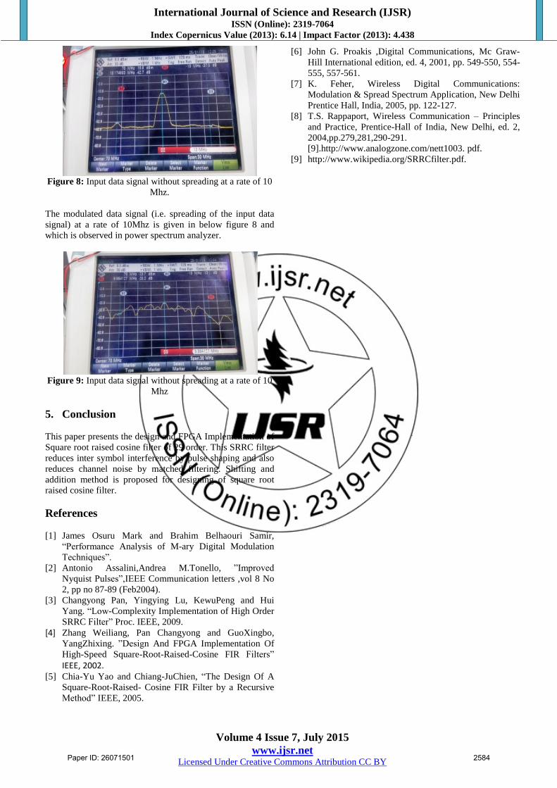
The input data signal which is used to transmit the signal at a
rate of 10Mhz is given in below figure 8 and which is
observed in power spectrum analyzer.
Paper ID: 26071501 2583
International Journal of Science and Research (IJSR) ISSN (Online): 2319-7064
Index Copernicus Value (2013): 6.14 | Impact Factor (2013): 4.438
Volume 4 Issue 7, July 2015
www.ijsr.net Licensed Under Creative Commons Attribution CC BY
Figure 8: Input data signal without spreading at a rate of 10
Mhz.
The modulated data signal (i.e. spreading of the input data
signal) at a rate of 10Mhz is given in below figure 8 and
which is observed in power spectrum analyzer.
Figure 9: Input data signal without spreading at a rate of 10
Mhz
5. Conclusion
This paper presents the design and FPGA Implementation of
Square root raised cosine filter of 29 order. This SRRC filter
reduces inter symbol interference by pulse shaping and also
reduces channel noise by matched filtering. Shifting and
addition method is proposed for designing of square root
raised cosine filter.
References
[1] James Osuru Mark and Brahim Belhaouri Samir,
“Performance Analysis of M-ary Digital Modulation
Techniques”.
[2] Antonio Assalini,Andrea M.Tonello, ”Improved
Nyquist Pulses”,IEEE Communication letters ,vol 8 No
2, pp no 87-89 (Feb2004).
[3] Changyong Pan, Yingying Lu, KewuPeng and Hui
Yang. “Low-Complexity Implementation of High Order
SRRC Filter” Proc. IEEE, 2009.
[4] Zhang Weiliang, Pan Changyong and GuoXingbo,
YangZhixing. ”Design And FPGA Implementation Of
High-Speed Square-Root-Raised-Cosine FIR Filters”
IEEE, 2002. [5] Chia-Yu Yao and Chiang-JuChien, “The Design Of A
Square-Root-Raised- Cosine FIR Filter by a Recursive
Method” IEEE, 2005.
[6] John G. Proakis ,Digital Communications, Mc Graw-
Hill International edition, ed. 4, 2001, pp. 549-550, 554-
555, 557-561.
[7] K. Feher, Wireless Digital Communications:
Modulation & Spread Spectrum Application, New Delhi
Prentice Hall, India, 2005, pp. 122-127.
[8] T.S. Rappaport, Wireless Communication – Principles
and Practice, Prentice-Hall of India, New Delhi, ed. 2,
2004,pp.279,281,290-291.
[9].http://www.analogzone.com/nett1003. pdf.
[9] http://www.wikipedia.org/SRRCfilter.pdf.
Paper ID: 26071501 2584