Embed Size (px)
Citation preview

FPA2 Universal Adapter for EPIShort description of congatec’s universal flat panel adapter
Short Description
Revision 1.0

Copyright © 2010 congatec AG FPA2m10 2/20
Revision HistoryRevision Date (dd.mm.yy) Author Changes1.0 23.12.10 GDA Official release

Copyright © 2010 congatec AG FPA2m10 3/20
PrefaceThis short description provides information about the features, connectors and schematics for the FPA2.
Disclaimer
The information contained within this short description, including but not limited to any product specification, is subject to change without notice.
congatec AG provides no warranty with regard to this short description or any other information contained herein and hereby expressly disclaims any implied warranties of merchantability or fitness for any particular purpose with regard to any of the foregoing. congatec AG assumes no liability for any damages incurred directly or indirectly from any technical or typographical errors or omissions contained herein or for discrepancies between the product and the short description. In no event shall congatec AG be liable for any incidental, consequential, special, or exemplary damages, whether based on tort, contract or otherwise, arising out of or in connection with this short description or any other information contained herein or the use thereof.
Intended Audience
This short description is intended for technically qualified personnel. It is not intended for general audiences.

Copyright © 2010 congatec AG FPA2m10 4/20
Symbols
The following symbols are used in this user’s guide:
Warning
Warnings indicate conditions that, if not observed, can cause personal injury.
Caution
Cautions warn the user about how to prevent damage to hardware or loss of data.
Note
Notes call attention to important information that should be observed.
Connector Type
Describes the connector that must be used with the FPA2, not the connector found on the FPA2.
Link to connector layout diagram
This link icon is located in the top right corner of each page. It provides a direct link to the connector layout on page 10 of this document.

Copyright © 2010 congatec AG FPA2m10 5/20
Terminology
Term DescriptionEPI Embedded Panel InterfaceEDID™ Extended Display Identification Data is a VESA standard data format that contains basic information about a displayFPA2 Flat panel Prototype Adapter 2LVDS Low Voltage Differential Signaling, a low noise, low power, low amplitude method for high-speed data transmission TTL Transistor-Transistor logic, a common type of digital circuit in which the output is derived from two transistors I²C Bus Inter-Integrated Circuit Bus: is a simple two-wire bus with a software-defined protocol that was developed to provide
the communications link between integrated circuits in a system.
Copyright Notice
Copyright © 2010, congatec AG. All rights reserved. All text, pictures and graphics are protected by copyrights. No copying is permitted without written permission from congatec AG.
congatec AG has made every attempt to ensure that the information in this document is accurate yet the information contained within is supplied “as-is”.
Trademarks
Product names, logos, brands, and other trademarks featured or referred to within this user’s guide, or the congatec website, are the property of their respective trademark holders. These trademark holders are not affiliated with congatec AG, our products, or our website.

Copyright © 2010 congatec AG FPA2m10 6/20
Warranty
congatec AG makes no representation, warranty or guaranty, express or implied regarding the products except its standard form of limited warranty (“Limited Warranty”). congatec AG may in its sole discretion modify its Limited Warranty at any time and from time to time.
Beginning on the date of shipment to its direct customer and continuing for the published warranty period, congatec AG represents that the products are new and warrants that each product failing to function properly under normal use, due to a defect in materials or workmanship or due to non conformance to the agreed upon specifications, will be repaired or exchanged, at congatec AG’s option and expense.
Customer will obtain a Return Material Authorization (“RMA”) number from congatec AG prior to returning the non conforming product freight prepaid. congatec AG will pay for transporting the repaired or exchanged product to the customer.
Repaired, replaced or exchanged product will be warranted for the repair warranty period in effect as of the date the repaired, exchanged or replaced product is shipped by congatec AG, or the remainder of the original warranty, whichever is longer. This Limited Warranty extends to congatec AG’s direct customer only and is not assignable or transferable.
Except as set forth in writing in the Limited Warranty, congatec AG makes no performance representations, warranties, or guarantees, either express or implied, oral or written, with respect to the products, including without limitation any implied warranty (a) of merchantability, (b) of fitness for a particular purpose, or (c) arising from course of performance, course of dealing, or usage of trade.
congatec AG shall in no event be liable to the end user for collateral or consequential damages of any kind. congatec AG shall not otherwise be liable for loss, damage or expense directly or indirectly arising from the use of the product or from any other cause. The sole and exclusive remedy against congatec AG, whether a claim sound in contract, warranty, tort or any other legal theory, shall be repair or replacement of the product only

Copyright © 2010 congatec AG FPA2m10 7/20
Certification
congatec AG is certified to DIN EN ISO 9001:2008 standard.
Technical Support
congatec AG technicians and engineers are committed to providing the best possible technical support for our customers so that our products can be easily used and implemented. We request that you first visit our website at www.congatec.com for the latest documentation, utilities and drivers, which have been made available to assist you. If you still require assistance after visiting our website then contact our technical support department by email at [email protected]
Lead-Free Designs (RoHS)
All congatec AG designs are created from lead-free components and are completely RoHS compliant.
Electrostatic Sensitive Device
All congatec AG products are electrostatic sensitive devices and are packaged accordingly. Do not open or handle a congatec AG product except at an electrostatic-free workstation. Additionally, do not ship or store congatec AG products near strong electrostatic, electromagnetic, magnetic, or radioactive fields unless the device is contained within its original manufacturer’s packaging. Be aware that failure to comply with these guidelines will void the congatec AG Limited Warranty.

Copyright © 2010 congatec AG FPA2m10 8/20
Contents1 Introduction ................................................................................ 9
2 Connector Layout ..................................................................... 10
3 Connectors ............................................................................... 11
3.1 X1 Connector EPI Input ........................................................... 113.2 X2 Power Input ........................................................................ 123.3 X2 TTL Output-Single/First Pixel Mode Data ........................... 133.4 X6 Panel Power Connector ..................................................... 14
4 Brightness Control ................................................................... 15
5 Configuration ............................................................................ 16
5.1 Timing ...................................................................................... 165.2 Jumper Configurations ............................................................. 16
6 Mechanical Dimensions ........................................................... 17
7 Maximum Ratings .................................................................... 18
7.1 Power Ratings .......................................................................... 187.2 Environmental Specifications ................................................... 18
8 FPA2 Schematics ..................................................................... 19

Copyright © 2010 congatec AG FPA2m10 9/20
Introduction1 FPA2 (Flat panel Prototype Adapter 2) is a universal adapter board that has been designed for use with congatec’s Embedded Panel Interface (EPI). It can be used for either prototyping, demonstration purposes, or for debugging certain issues. It may also serve as a reference for the implementation of panel adaptations on customer specific carrier boards. This document is one of several that should be referred to while using or implementing FPA2 features and/or functions. The following congatec documents should be referenced:
congatec Backlight Control Design Guide (DG_BacklightControl_1x.pdf)•
congatec System Utility (CGUTLm1x.pdf)•
The User’s Guide for the congatec product that will be used with the FPA2.•
Links to these documents can be found at www.congatec.com. The following are industry standard documents that should be referred to as well. They include:
EPI Specification from the EPI consortium at www.epi-standard.org•
E-EDIDTM Implementation Guide Version 1.0 from VESA under the file name • EEDIDguideV1.pdf at www.vesa.org/public
Open LVDS Display Interface Specification v0.95 from National Semiconductor at http://www.national.com/appinfo/fpd/0,2132,228,00.html•
Digital Visual Interface DVI Revision 1.0 from the Digital Display Working Group found at www.ddwg.org/downloads.asp•
SPWG v3.5 Specification from the Standard Panel Working Group found at www.spwg.org•
The FPA2 is capable of several functions designed to assist you during the evaluation and implementation of flat panel support. They are as follows:
Power sequencing for panel and backlight.•
Serial I²C EEPROM to store the EPI enhanced EDID™ file.•
D/A converter enabling backlight brightness control.•
3.3V power supply for low-voltage panels.•
Panel and backlight supply voltage can be configured by jumpers.•

Copyright © 2010 congatec AG FPA2m10 10/20
Connector Layout2 The connector layout picture below shows the silkscreen of the FPA2, which indicates pinout as well as name designators.
Select the Adobe ‘Zoom-In-Tool’ and zoom in on a given component to see the descriptive silkscreen text. Hover over the component and the ‘Zoom-In-Tool’ will change indicating there is a link. Click on the link to navigate to the area in the document where the component is described in detail.
Use the mouse icon in the top left hand corner of the destination page to return to the connector layout picture.
Copyright © 2010 congatec AG FPA2m10 11/20
Connectors3 The following section describes the connectors located on the FPA2. Each connector’s pinout is listed as well a description of the mating connector that should be used to connect to the specific connector located on the FPA2.
3.1 X1 Connector EPI InputFor a detailed description of the signals listed in the pinout table below refer to the EPI Specification.
Pin Signal Name LVDS mode TTL mode Pin Signal Name LVDS mode TTL mode1 LCD_DDC_DAT I²C EPI DATA 18 LCDD9 FL3P GREEN32 LCD_DDC_CLK I²C EPI Clock 19 LCDD8 FL3N GREEN23 - Currently unused 20 GND GND4 - Currently unused 21 LCDD10 SL0N GREEN45 GND GND 22 LCDD11 SL0P GREEN56 LCDD0 FL0N RED0 23 GND GND7 LCDD1 FL0P RED1 24 LCDD12 SL1N BLUE08 LCD_VDD_EN Enable Panel Power 25 LCDD13 SL1P BLUE19 LCDD2 FL1N RED2 26 GND GND10 LCDD3 FL1P RED3 27 LCDD14 SL2N BLUE211 LCD_BKLT_EN Enable Backlight Power 28 LCDD15 SL2P BLUE312 LCDD5 FL2P RED5 29 GND GND13 LCDD4 FL2N RED4 30 LCDD17 SLCP BLUE514 LCD_VSYNC VSYNC 31 LCDD16 SLCN BLUE415 LCDD6 FLCN GREEN0 32 Detect# Currently unused16 LCDD7 FLCP GREEN1 33 LCDD19 SL3P DE17 LCD_HSYNC HSYNC 34 LCDD18 SL3N DCLK
Connector Type
34 pin, 2 row 2mm grid female
EPI Input (X1)
34
33
32
31
30
29
28
27
26
25
24
23
22
21
20
19
18
17
16
15
14
13
12
11
10
9
8
7
6
5
4
3
2
1

Copyright © 2010 congatec AG FPA2m10 12/20
3.2 X7 Power InputThe power to the FPA2 is supplied via a 3.5’’ floppy connector. A quadratic pad on the bottom side indicates pin one. The pinout and connector are described below.
Pin Signal Name1 12V2 GND3 GND4 5V
Connector Type
Standard 4 pin 3.5’’ floppy power connector female
3.5'' FloppyConnector
4321

Copyright © 2010 congatec AG FPA2m10 13/20
3.3 X2 TTL Output-Single/First Pixel Mode DataThe X2 connector is used for LVDS/TTL mode. It is responsible for delivering the 18/24 bit single pixel mode data. The pinout and connector are described below.
Connector Type
40 pin, 2 row 2mm grid female
Pin Signal Pin Signal1 GND 21 GREEN52 DCLK 22 GND3 GND 23 GREEN64 RED0 24 GREEN75 RED1 25 BLUE06 RED2 26 GND7 GND 27 BLUE18 RED3 28 BLUE29 RED4 29 BLUE310 RED5 30 GND11 GND 31 BLUE412 RED6 32 BLUE513 RED7 33 BLUE614 GREEN0 34 GND15 GND 35 BLUE716 GREEN1 36 HSYNC17 GREEN2 37 VSYNC18 GREEN3 38 GND19 GND 39 DE20 GREEN4 40 GND
TTL Output Single/First Pixel (X2)34
33
36
35
38
37
40
39
32
31
30
29
28
27
26
25
24
23
22
21
20
19
18
17
16
15
14
13
12
11
10
9
8
7
6
5
4
3
2
1

Copyright © 2010 congatec AG FPA2m10 14/20
3.4 X6 Panel Power ConnectorThe power connector provides power and display orientation control for the flat panel. See section 5 of this document for jumper configuration settings. The pinout and connector are described below.
Connector Type
10 pin, 2 row 2.54mm grid female
Pin Function Pin Function1 Switched VDD 6 Backlight On (active high)2 Switched VBKL 7 Backlight Dimmer 0-4.7V3 +5V 8 Backlight On4 +12V 9 GND5 Enable Display (active high) 10 GND
Panel Power (X6)10
9
8
7
6
5
4
3
2
1
Copyright © 2010 congatec AG FPA2m10 15/20
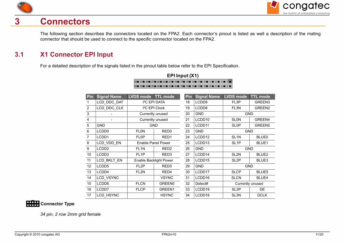
Brightness Control4 The backlight control is implemented using a MAXIM MAX5362MEUK voltage-output, 6-bit DAC that offers full 6-bit performance with less than 1LSB integral nonlinearity (INL) error and less than 1LSB differential nonlinearity (DNL) error ensuring monotonic performance. The device uses a simple two-wire, fastmode I2C-compatible serial interface. It includes an internal reference, an output buffer, and low-current shutdown mode, making it ideal for low-power, highly integrated applications. It is supported by the congatec embedded BIOS allowing for backlight brightness control. For additional information refer to the manufacturer’s datasheet.
Note
For more information about this subject refer to the EPI Specification and the user’s guide for the congatec System Utility as well as the congatec Backlight Control Design Guide.
VCC
DAC
U3
MAX5362MEUK
DAC
U3
VDD3
GND2
SCL5 SDA4 O 1
Copyright © 2010 congatec AG FPA2m10 16/20
Configuration5
Timing5.1 The panel timing is configured by an EPI/EDID™ configuration file, which is either stored on the congatec module or inside the FPA2 onboard EEPROM. It can be accessed through the I²C bus via the congatec System Utility.
Note
For more information about this subject refer to the EPI Specification and the user’s guide for the congatec System Utility.
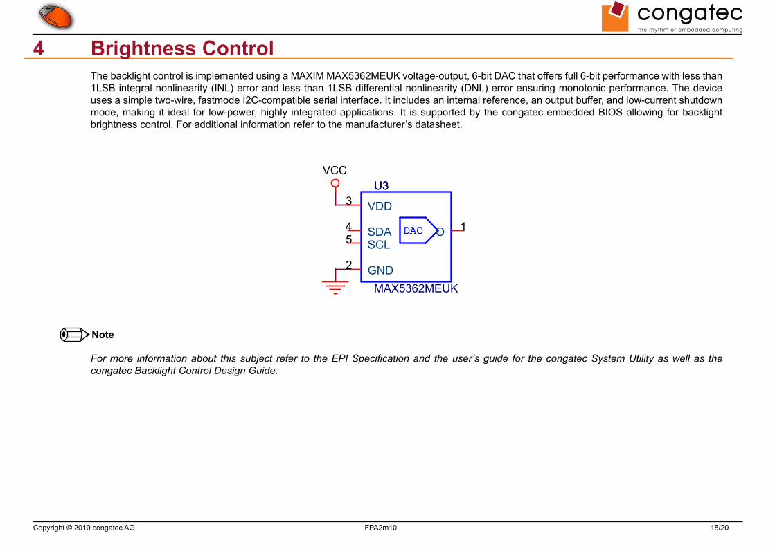
5.2 Jumper Configurations
Connector Type
JP1-3, 2,54mm grid jumpers
JP1: Panel voltage selector
Jumper JP1 Configuration1 - 2 +5V (default)2 - 3 +3.3V
JP2: Backlight inverter voltage
Jumper JP2 Configuration1 - 2 +12V (default)2 - 3 +5V
JP3: Backlight Polarity Config
Jumper JP3 Configuration1 - 2 Backlight enable HIGH active (default)2 - 3 Backlight enable LOW active

Copyright © 2010 congatec AG FPA2m10 17/20
Mechanical Dimensions6
TTL

Copyright © 2010 congatec AG FPA2m10 18/20
Maximum Ratings7
Power Ratings7.1 Input Voltage:
Signal Min. V Max. V5V 4.6V 5.2V12V 4.5V 12.5V
Output Current:
Signal @ Voltage Max. CurrentSwitched VDD 3.3V 0.6A
5V 2A12V 2A
Switched VBKL 5V / 12V 2A
Environmental Specifications7.2 Temperature Operation: 0° to 60°C Storage: -20° to +80°C
Humidity Operation: 10% to 90% Storage: 5% to 95%
Caution
The above operating temperatures must be strictly adhered to at all times. The maximum operating temperature refers to any measurable spot on the modules surface.
Humidity specifications are for non-condensing conditions.

Copyright © 2010 congatec AG FPA2m10 19/20
FPA2 Schematics8
FG1FG2FG6FG7FG3FG4FG5FB0FB6FB7FB1FB2
DVO_D19
DVO_D16
DVO_VSYNC
DVO_D17DVO_D18
DVO_D0
DVO_D1DVO_D2DVO_D3DVO_D4DVO_D5
DVO_D6DVO_D7
DVO_D8DVO_D9DVO_D10
DVO_D11
DVO_D20
DVO_D21
DVO_D22
DVO_D23
DVO_CLK
DVO_BLANK
DVO_D12DVO_D13
DVO_D14DVO_D15
DVO_HSYNC
LCDDO9LCDDO8
LCDDO7LCDDO6
LCDDO5LCDDO4
LCDDO3LCDDO2
LCDDO0
LCD_I2C_CLKLCD_I2C_DAT
LCDDO1
FR6
FB3FB4FB5
FR0FR1FR2FR3
DVO_D[0..23]
LCDDO1LCDDO0LCDDO3LCDDO2LCDDO5LCDDO4LCDDO9LCDDO8
LCDDO7
FR4FR7FR5FG0
LCDDO6
DVO_D17DVO_D18DVO_D19DVO_D20DVO_D21DVO_D22DVO_D23
DVO_BLANKDVO_VSYNCDVO_HSYNC
DVO_D[0..23]
DVO_D0DVO_D1DVO_D2DVO_D3
DVO_D8
DVO_D4
DVO_D9
DVO_D5
DVO_D10
DVO_D6DVO_D7
DVO_D11DVO_D12DVO_D13DVO_D14DVO_D15
DVO_CLK
DVO_D16
PD_LVDS
LVDS_VDD_EN
VCC3
VCC3
LCD_I2C_CLKLCD_I2C_DAT
LVDS_BKLT_ENLVDS_VDD_EN
Red0Red1Red2Red3Red4
Red5
Red6
Red7
Green0Green1Green2
Green3Green4Green5
Green6Green7
Blue0
Blue1Blue2Blue3Blue4Blue5
Blue6Blue7
LVDS-TTL
Connector TTL-OUT
Connector LVDS-IN
np
RN2 RN33RVFRN2 RN33RVF
1357
2468
R5R5%10kS03R5R5%10kS03
12
R7 R5%33RS03R7 R5%33RS03
FB1FB1
U1
UDS90C386
U1
UDS90C386
PDN25
RXCLKOUT 26
RXIN0-9 RXIN0+10
RXIN1-11 RXIN1+12
RXIN2-15 RXIN2+16
RXIN3-19 RXIN3+20
RXCLKIN-17 RXCLKIN+18
RXOUT0 27RXOUT1 29RXOUT2 30RXOUT3 32RXOUT4 33RXOUT5 34RXOUT6 35RXOUT7 37RXOUT8 38RXOUT9 39
RXOUT10 41RXOUT11 42RXOUT12 43RXOUT13 45RXOUT14 46RXOUT15 47RXOUT16 49RXOUT17 50RXOUT18 51RXOUT19 53RXOUT20 54RXOUT21 55RXOUT22 1RXOUT23 2RXOUT24 3RXOUT25 5RXOUT26 6RXOUT27 7
GND4GND28GND36GND44GND52
LVDSVCC13PLLVCC23PLLGND22PLLGND24LVDSGND8LVDSGND14LVDSGND21
VCC31VCC40VCC48VCC56
C2C10uS05V16XC2C10uS05V16X
RN4 RN33RVFRN4 RN33RVF
1357
2468
FB3
FB120R0A5S03
FB3
FB120R0A5S03
R2R2
RN1 RN33RVFRN1 RN33RVF
1357
2468
C4C4
FB2FB2
X2
XST2MMTH2x20
X2
XST2MMTH2x20
RED38RED49
BLUE735
RED612RED713
SHFTCLK2
RED510
GREEN014
GND 1
GREEN116GREEN217
GND 3
GREEN318GREEN420
GND 7
GREEN521GREEN623
GND 26
GREEN724
BLUE025
GND 30
BLUE127BLUE228
GND 34
BLUE329BLUE431
GND 38
BLUE532BLUE633
GND 40
GND 15GND 11
GND 19GND 22
RED26 RED15 RED04
DE39 VSYNC37 HSYNC36
R1R5%100RS03
R1R5%100RS03
C5C5
R4R4
R3R3
R24R5%0R0S03
R24R5%0R0S03
RN6 RN33RVFRN6 RN33RVF
1357
2468
R8 R5%33RS03R8 R5%33RS03
R6R6
RN3 RN33RVFRN3 RN33RVF
1357
2468
R10 R5%33RS03R10 R5%33RS03
X1
XST2MMTH2x17
X1
XST2MMTH2x17
LCDDO0 6LCDDO1 7
DIGON 8
LCDDO2 9LCDDO3 10
BLON# 11
LCDDO4 13LCDDO5 12
BIASON 17
LCDDO6 15LCDDO7 16
LTGIO 14
LCDDO8 19LCDDO9 18
DETECT# 32
LCDDO10 21LCDDO11 22
GND5
LCDDO12 24LCDDO13 25
GND20
LCDDO14 27LCDDO15 28
GND23
LCDDO16 31LCDDO17 30
GND26
LCDDO18 34LCDDO19 33
GND29 LCD_I2CLK 2LCD_I2DAT 1
NC03 NC14
C3C3
R9 R5%33RS03R9 R5%33RS03
C6C10nS03V10X
C6C10nS03V10X
RN5 RN33RVFRN5 RN33RVF
1357
2468

Copyright © 2010 congatec AG FPA2m10 20/20
FPA2 Schematics Continued
BLON#
LVDS_BKLT_EN
SW_VDD_SRC
BLON#
SW_VDD
SW_BACK
LVDS_VDD_EN
SW_VDD
LCD5VSW_BACK_SRC
SW_BACKLCD12V
SW_BACKSW_VDD
LVDS_VDD_EN
LCD5V
LCD5V
LCD_I2C_DATLCD_I2C_CLK
LCD12V
LCD_I2C_DATLCD_I2C_CLK
VCC
VCC3
VCC +12V
VCC
VCC
VCC
VCC3
VCCIN VCCIN
VCC
+12V
LVDS_BKLT_EN(2)
LCD_I2C_DATLCD_I2C_CLK
LVDS_VDD_EN
set jumper 1-2 for non invert (default)set jumper 2-3 for inverted siganl on connector
np
np
set jumper 1-2 for 5V LCD voltage (default)set jumper 2-3 for 3.3V LCD voltage
set jumper 1-2 for 12V backlight voltage (default)set jumper 2-3 for 5V backlight voltage
EPI-EEPROM
R22
R5%0R0S03
R22
R5%0R0S03
C13C10uS05V16XC13C10uS05V16X
F2 FMINISMDM200FF2 FMINISMDM200F
R14
R5%100RS03
R14
R5%100RS03
R23
R5%0R0S03
R23
R5%0R0S03
F3 FNANOSMDC150F3 FNANOSMDC150
C10C10uS05V16X
C10C10uS05V16X
D3
DMBR130LSFT1
D3
DMBR130LSFT1
C7
C10nS03V10X
C7
C10nS03V10X
DAC
U3
UMAX5362
DAC
U3
UMAX5362
VDD3
GND2
SCL5 SDA4 O 1
C9C10uS05V16XC9C10uS05V16X
T2TMMBT3904T2TMMBT3904
2
1
3
JP3
XST1x3S
JP3
XST1x3S
1 12 23 3R19R5%1k0S03
R19R5%1k0S03
F4 FMINISMDM200FF4 FMINISMDM200F
T3TMMBT3904T3TMMBT3904
2
1
3
+ C15CLE330UD6E10
+ C15CLE330UD6E10
T4TMMBT3904T4TMMBT3904
2
1
3
U2
AT24C02
U2
AT24C02
A01A12A23 GND 4
SDA5SCL6
WP7
VCC 8
X7
XTHFLPYPWR
X7
XTHFLPYPWR
1 12 23 34 4
X6
XSHEAD10
X6
XSHEAD10
11 2 233 4 455 6 677 8 899 10 10
D2
DLED1206RED
D2
DLED1206REDR20R5%10kS03R20R5%10kS03
R16R5%10kS03R16R5%10kS03
M10
MJMPR254
M10
MJMPR254
T1ATSI9933BDY
T1ATSI9933BDY
2
1 78
R18R5%10kS03
R18R5%10kS03
M8
MJMPR254
M8
MJMPR254
R21R5%10kS03R21R5%10kS03
U4ULT1117CST3V3U4ULT1117CST3V3
VIN3 VOUT 2
AD
J1
VOUTPAD 4
C12C100nS03V10XC12C100nS03V10X
F1FNANOSMDC150
F1FNANOSMDC150
D1
DLED1206RED
D1
DLED1206RED
JP1
XST1x3S
JP1
XST1x3S
1 12 23 3
M9
MJMPR254
M9
MJMPR254
R11R11
C14C10uS05V16XC14C10uS05V16X
R17R5%1k0S03
R17R5%1k0S03
T1BTSI9933BDY
T1BTSI9933BDY
4
3 56
C11C10nS03V10X
C11C10nS03V10X
R12R12
JP2
XST1x3S
JP2
XST1x3S
1 12 23 3
R15R5%10kS03R15R5%10kS03
R13R5%10kS03R13R5%10kS03 C8
C10nS03V10XC8
C10nS03V10X