Embed Size (px)
Citation preview
Grant agreement no.: 218575
FP7 Project 2007-Grant agreement n◦: 218575
Project Acronym: INESSProject Title: INtegrated European Signalling System
Instrument: Large-scale integrating projectThematic Priority: Transport
Document Title:
INESS WS D Deliverable D.4.5.1 Prototype of a tool forverification Report
Due date of deliverable M24Actual submission date M24
Deliverable ID: D.D.4.5.1Deliverable Title: Prototype of a tool for verificationWP Related: WP D.4Responsible partner: LaQuSo (TU/e, UT), Southampton, YorkTask/Deliverable leader Name: Helle Hvid HANSEN, LaQuSo (TU/e, UT)Contributors: LaQuSo (TU/e, UT), Southampton, York
Start date of the project: 01-10-2008 Duration: 36 Months
Project coordinator: George BarbuProject coordinator organisation: UIC
Revision: Final Dissemination Level1: CO
DISCLAIMER
The information in this document is provided “as is”, and no guarantee or warranty is given that the information is fit forany particular purpose. The user thereof uses the information at its sole risk and liability.
PROPRIETARY RIGHTS STATEMENT
This document contains information, which is proprietary to the INESS Consortium. Neither this document nor theinformation contained herein shall be used, duplicated or communicated by any means to any third party, in whole or in
parts, except with prior written consent of the INESS consortium.
1PU: Public, PP: Restricted to other programme participants (including the Commission Services), RE: Restricted to a group specified by theconsortium (including the Commission Services), CO: Confidential, only for members of the consortium (including the Commission Services).
. . . . . . . . . . . . . . . . . . . . . . . . . . . . . . . . . . . . . . . . . . . . . . . . . . . . . . . . . . . . . . . . . . . . . . . . . . . . . . . . . . . . . . . . . . . . . . . . . . . .INESS WS D Deliverable D.4.5.1 Prototype of a tool for verification Report Ver2010-10-22Date: 2010-10-22Revision: Final Security: Confidential — Consortium Only Page 1/ 17

Grant agreement no.: 218575
Document Information
Document type: ReportDocument Name: INESS WS D Deliverable D.4.5.1 Prototype of a tool for verification Report Ver2010-10-22Revision: FinalRevision Date: 2010-10-22Author: LaQuSo (TU/e, UT), Southampton, YorkDissemination level: CO
Approvals
Name Company Date Visa
WP leader Khalid AGROU UIC
WS leader Wim van SPRONSEN ProRail
Project Manager Emmanuel BUYSENE UIC
Steering Board
Document history
Revision Date Modification AuthorInitial 2010-10-14 H. H. Hansen (LaQuSo)Final 2010-10-22 H. H. Hansen (LaQuSo)
TABLE OF CONTENTS
GLOSSARY . . . . . . . . . . . . . . . . . . . . . . . . . . . . . . . . . . . . . . . . . . . . . . . . . . 3Section 1. EXECUTIVE SUMMARY . . . . . . . . . . . . . . . . . . . . . . . . . . . . . . . . . . . . 4Section 2. INTRODUCTION . . . . . . . . . . . . . . . . . . . . . . . . . . . . . . . . . . . . . . . . 5Section 3. VERIFICATION APPROACH . . . . . . . . . . . . . . . . . . . . . . . . . . . . . . . . . . 7Section 4. PROTOTYPE . . . . . . . . . . . . . . . . . . . . . . . . . . . . . . . . . . . . . . . . . . . 11Section 5. CONCLUSION . . . . . . . . . . . . . . . . . . . . . . . . . . . . . . . . . . . . . . . . . . 16Bibliography . . . . . . . . . . . . . . . . . . . . . . . . . . . . . . . . . . . . . . . . . . . . . . . . . 17
. . . . . . . . . . . . . . . . . . . . . . . . . . . . . . . . . . . . . . . . . . . . . . . . . . . . . . . . . . . . . . . . . . . . . . . . . . . . . . . . . . . . . . . . . . . . . . . . . . . .INESS WS D Deliverable D.4.5.1 Prototype of a tool for verification Report Ver2010-10-22Date: 2010-10-22Revision: Final Security: Confidential — Consortium Only Page 2/ 17

Grant agreement no.: 218575
GLOSSARY
Artisan Studio UML modelling tool suite. URL: http://www.atego.com/products/artisan-studio/.
Eclipse An open source software development environment comprising an integrated development environ-ment and an extensible plug-in system. URL: http://www.eclipse.org.
Epsilon Eclipse-based model transformation tool set. URL: http://www.eclipse.org/gmt/epsilon/doc/etl/.
KnowGravity Inc. (Consultancy). URL: http://www.knowgravity.com.
LTSmin Tool set providing symbolic model checking for the mCRL2 specification language, cf. [2]. URL: http://fmt.cs.utwente.nl/tools/ltsmin/.
mCRL2 A formal specification language, as well as the name of the associated tool set, cf. [5]. URL: http://www.mcrl2.org.
Micro 2010 An experimental, minimum functionality interlocking xUML model provided by KnowGravityInc.
Papyrus An Eclipse-based UML editor. URL: www.papyrusuml.org.
Rodin Theorem prover associated with UML-B. URL: http://wiki.event-b.org/index.php/Rodin_Platform
UML Unified Modeling Language, a standardized general-purpose modeling language managed and createdby the Object Management Group. URL: http://www.uml.org.
UML-B Modelling tool based on model refinement techniques. URL: http://wiki.event-b.org/index.php/UML-B.
XMI XML Metadata Interchange, an Object Management Group (OMG) standard for exchanging metadatainformation via Extensible Markup Language (XML).
xUML Executable UML, an executable subset of UML.
. . . . . . . . . . . . . . . . . . . . . . . . . . . . . . . . . . . . . . . . . . . . . . . . . . . . . . . . . . . . . . . . . . . . . . . . . . . . . . . . . . . . . . . . . . . . . . . . . . . .INESS WS D Deliverable D.4.5.1 Prototype of a tool for verification Report Ver2010-10-22Date: 2010-10-22Revision: Final Security: Confidential — Consortium Only Page 3/ 17

Grant agreement no.: 218575
Section 1 — EXECUTIVE SUMMARY
The verification task D.4.5 of the universities is a major undertaking, and it requires the aid of software tools.The first part of task D.4.5 consists of developing and adapting these tools. The current deliverable D.4.5.1presents a prototype of the verification tools developed for our model checking approach to verification. Theprototype demonstrates the model checking process using Micro 2010, an experimental xUML model of avery simple interlocking. We conduct verification of three safety invariants mentioned in the Micro 2010documentation. These three safety invariants have been modelled in xUML as well. The tool allows the user tospecify a track layout for Micro 2010, and to choose which safety invariants to verify. If an invariant is violated,a so-called error trace is generated and visualised as a UML message sequence diagram. Such an error traceprovides the user with a concrete scenario in which the safety invariant is violated, and can be used as feedbackto the modelling and specification process.
. . . . . . . . . . . . . . . . . . . . . . . . . . . . . . . . . . . . . . . . . . . . . . . . . . . . . . . . . . . . . . . . . . . . . . . . . . . . . . . . . . . . . . . . . . . . . . . . . . . .INESS WS D Deliverable D.4.5.1 Prototype of a tool for verification Report Ver2010-10-22Date: 2010-10-22Revision: Final Security: Confidential — Consortium Only Page 4/ 17

Grant agreement no.: 218575
Section 2 — INTRODUCTION
One of the objectives of work package D.4 (WP D.4) is to verify a core set of functional requirements for inter-locking systems modelled in Executable UML (xUML) (Task D.3.3, UIC). The general strategy to achieve thisaim was presented in deliverable D.4.1. The aim of verification is to show that the interlocking xUML modelsatisfies certain requirements that are not directly expressed as functional requirements. These requirementsinclude safety requirements such as those that prevent collisions and derailment.
In order to perform the verification of interlocking xUML models quickly and accurately, we are developingsoftware tools. For this we take existing software and technology as a starting point and develop extensions andadaptations to make them suitable for the verification of interlocking xUML models. Most notably, we needto develop and implement translators (translating xUML models to the input languages of existing software,and translating the output back to UML), and we need to adapt the existing software for the specific task ofverifying safety invariants. Deliverable D.4.5.1, associated with the first part of Task D.4.5 of work packageD.4, is a prototype of the verification tool that is being developed. The prototype is described in the currentdocument consists of the following tools:
Translation tools for translating interlocking xUML models and safety invariants into the formal specificationlanguage mCRL2.
Model checking tools for verifying that the safety invariants hold in the interlocking model, and for generatingan error trace if a safety violation is found.
Trace visualisation tool for displaying error traces in the form of a UML message sequence diagram.
A more detailed description of the tools can be found in Section 4. The CD accompanying this report containsall the above tools.
The work carried out by us in order to realise the prototype functionality is summarised below.
Expressing safety invariants for verification: Safety invariants are often provided in natural language. In orderto verify them, they must be formalised. We formalise safety invariants in xUML in a style similar tohow the xUML interlocking models are specified. We point out that the formalisations presented in thisreport are meant to illustrate a method; we do not claim that these formalisations are correct with respectto the intended meaning of the safety invariants.
Generating XMI: The interlocking model must be provided to the automated translation in an XMI formatcompatible with the UML2 Standard of Eclipse. The xUML interlocking models are created in ArtisanStudio. We have created a software tool which takes an Artisan model as input and produces as outputan identical model in XMI.
Translation from xUML to mCRL2: We have implemented a program which takes as input: an xUML modelM (provided in XMI format), a track layout, a safety invariant xUML model, an instantiation of the safetyinvariant model. The translation program transforms the input to a model whose structure is closer to theprocess-based formalism of mCRL2. From this model, the mCRL2 code is finally generated.
Trace visualisation: If a safety violation was found by the model checking tools, an error trace is produced.This trace is just a sequence of actions in plain-text format. We have created a trace visualisation toolwhich takes the plain-text trace and generates a UML message sequence diagram.
. . . . . . . . . . . . . . . . . . . . . . . . . . . . . . . . . . . . . . . . . . . . . . . . . . . . . . . . . . . . . . . . . . . . . . . . . . . . . . . . . . . . . . . . . . . . . . . . . . . .INESS WS D Deliverable D.4.5.1 Prototype of a tool for verification Report Ver2010-10-22Date: 2010-10-22Revision: Final Security: Confidential — Consortium Only Page 5/ 17

Grant agreement no.: 218575
User interface: A simple user interface has been created in order to make the tool easier to use by people whoare not familiar with the internal workings of the underlying tools.
In order to demonstrate the verification process, the prototype uses as an example the Micro 2010 inter-locking xUML model (an example provided by KnowGravity Inc.) and three safety invariants formulated inthe Micro 2010 document [7].
A second technique of formal verification which we described in D.4.1 is to apply theorem provers to amodel in order to verify that the required properties hold. We give a brief report on the status of this approach.
In this report, we focus on functionality aspects rather than implementation details, although some descrip-tion of the developed software will be given. The rest of this document is structured as follows. In Section 3.1,we briefly recall the model checking verification approach. In particular, we describe how safety invariants areverified by expressing them in xUML. We describe the progress of the development of our theorem provingtools in Section 3.2. An overview of the structure, functionality and implementation of the prototype is givenin Section 4. Finally, we conclude in Section 5.
. . . . . . . . . . . . . . . . . . . . . . . . . . . . . . . . . . . . . . . . . . . . . . . . . . . . . . . . . . . . . . . . . . . . . . . . . . . . . . . . . . . . . . . . . . . . . . . . . . . .INESS WS D Deliverable D.4.5.1 Prototype of a tool for verification Report Ver2010-10-22Date: 2010-10-22Revision: Final Security: Confidential — Consortium Only Page 6/ 17

Grant agreement no.: 218575
Section 3 — VERIFICATION APPROACH
3.1 Model checking
In model checking, a formal model is a mathematically precise description of all possible behaviours of asystem. By an exhaustive inspection of the formal model, it is determined whether a certain desired property(for example, a safety invariant) is satisfied by all system behaviours. In order to perform model checkingon interlocking xUML models, we must first obtain a formal model and express the safety invariants in aformat compatible with the formal model. In our model checking approach, the generic interlocking xUMLmodel together with a track layout instance are translated to the formal specification language mCRL2. ThismCRL2 specification serves as the input to the model checking tools mCRL2 and LTSmin. We demonstrate ourapproach by verifying three safety invariants formulated in natural language in the Micro 2010 document [7].We model these invariants in xUML, an idea which is based on the approach to testing using “negative test caseobservers” by Crispin de Courcey-Bayley and Markus Schacher of KnowGravity Inc., see [3, 4]. This modellingof invariants, however, is a non-trivial task and we do not claim that the current formalisation captures theintended interpretation of the safety invariants. Our aim is rather to demonstrate a method of how the invariantscan be formalised. Our motivation for expressing the safety invariants in UML is that we believe it will facilitatediscussions between us, the UML modellers and the railways on the correct interpretation of these invariants.It also has the advantage that we can reuse the code that carries out the translation from UML to mCRL2 of theinterlocking model.
3.1.1 Interlocking models
As already pointed out in the earlier deliverable D.4.1, the common core Interlocking Model (deliverable D.3.3)is not yet available to us, and we therefore base our work on a number of example interlocking models: MicroI, Micro II and Micro 2010. These models have been kindly provided to us by KnowGravity Inc. In thecurrent prototype, we demonstrate our verification technique using the Micro 2010 interlocking [7], whoseclass diagram we show in Figure 3.1.
3.1.2 Safety invariants
In this prototype, a safety invariant is expressed as a so-called “observer”. This observer is a UML state machinewhich “observes” the state of the system and whenever a violation of the invariant is found it generates an errorsignal and deadlocks the system. Safety violations can therefore be found using the existing deadlock detectionfunctionality of the model checking tools.
The observers are specified in a generic xUML model separate from the interlocking xUML model. Duringthe automated translation, the two models are transformed into an internal model that captures both. Fortechnical reasons, each observer instance must be associated with an “observed object” (and the class of thisobserved object) from the interlocking model instance. In fact, an observer of objects of type X is a UMLclass which can be seen to specialise the UML class X . In particular, the observer may access the attributesand associations of the observed object. In other words, the observer state machine is a subcomponent of theobserved object.
Since the observer state machines make explicit reference to the states, attributes and associations of objects,different interlocking models generally require different observer classes to express a safety invariant P. Forthis deliverable, we have expressed two safety invariants for the Micro 2010 interlocking. These are taken fromthe Micro 2010 document from which we quote [7, section 2.2.6].
. . . . . . . . . . . . . . . . . . . . . . . . . . . . . . . . . . . . . . . . . . . . . . . . . . . . . . . . . . . . . . . . . . . . . . . . . . . . . . . . . . . . . . . . . . . . . . . . . . . .INESS WS D Deliverable D.4.5.1 Prototype of a tool for verification Report Ver2010-10-22Date: 2010-10-22Revision: Final Security: Confidential — Consortium Only Page 7/ 17

Grant agreement no.: 218575
Figure 3.1: Class diagram of Micro 2010 interlocking.
S 0001 “A point that is locked by an established route shall never move.”
S 0002 “The entry signal of an established route shall never display proceed when one of its tracks is occupied.”
S 0002a “If a route is established and one of its tracks is occupied, then the entry signal of the route shall neverchange from a stop aspect to a proceed aspect.”
The invariant S 0002a is a refinement of S 0002 that we added in order to be able to exclude scenarioswhere the entry signal of an established route shows proceed, and subsequently a track in the route becomesoccupied. Such a scenario is a violation of S 0002, but given that a proceed signal should allow a train toenter the route, one might not consider it a real violation. We do not wish to discuss the correctness of theformulation of this invariant here, but use it as an illustration for how different interpretations of an invariantcan be formalised in xUML.
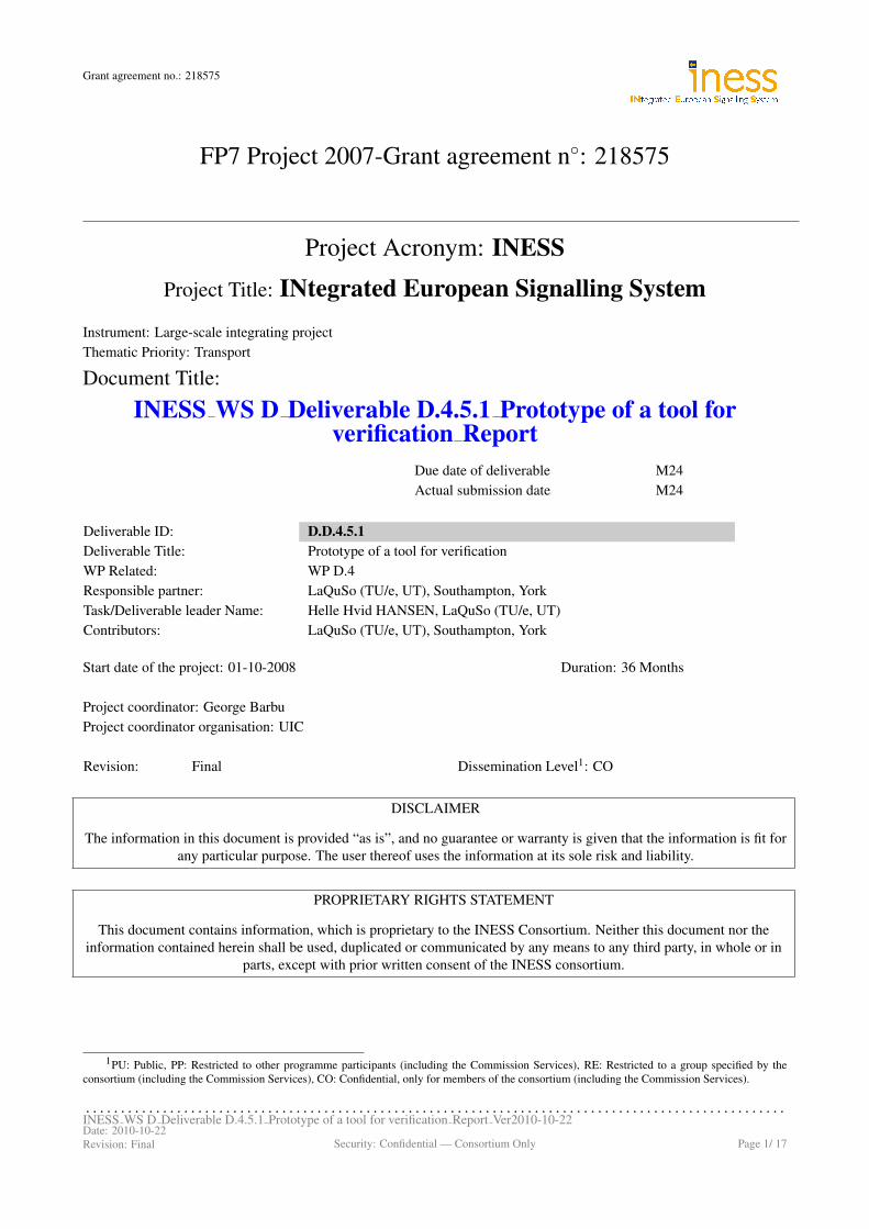
Figures 3.2, 3.4 and 3.3 (on page 9) show the state machines expressing the invariants S 0001, S 0002 andS 0002a, respectively. Figure 3.5 (on page 10) shows the class diagram of the observer model. As an example,we briefly describe the state machine for S 0001. The invariant S 0001 is an observer of objects of type pointin the Micro 2010 interlocking model. The transition from the state idle to the state active is triggered bythe change condition /is_locked and has as guard not /moving. The change condition refers to the derivedattribute /is_locked in the point class, and the guard refers to the derived attribute /moving which is definedin the S 0001 class itself. The actual definition is /moving := self.in_state(#working.moving) and ithappens as an effect of the initial transition to the state idle (in the figure, the assignment is shown as Effect,since Papyrus state machine diagrams do not display action language elements). Hence, /moving is true if andonly if the state moving is active in the observed point object. The transition from the state active to thestate violated can take place if a violation of S 0001 has been detected, and as the Effect on this transition,
. . . . . . . . . . . . . . . . . . . . . . . . . . . . . . . . . . . . . . . . . . . . . . . . . . . . . . . . . . . . . . . . . . . . . . . . . . . . . . . . . . . . . . . . . . . . . . . . . . . .INESS WS D Deliverable D.4.5.1 Prototype of a tool for verification Report Ver2010-10-22Date: 2010-10-22Revision: Final Security: Confidential — Consortium Only Page 8/ 17
Grant agreement no.: 218575
the message <i>_violation(property := S_0001) is sent to the environment (called GUI in Micro 2010).Again, the sending of this message is only shown as the label Effect on the transition from active to idle.In the translation to mCRL2, this message is treated differently from the other messages to the environment,and sending it will cause the entire system to deadlock.
In Figure 3.5, we show the class diagram of the observer model. The abstract class AbstractObserver hasno state machine associated with it, it just specifies that an observer is associated with an observed object andclass. The classes S_0001 and S_0002 are specialisations of AbstractObserver and in these classes derivedattributes can be declared that are needed in the definition of the state machine diagrams (Figures 3.2 and 3.3).The class BuildObservers creates the observer instances from an instantiation file as described in on page 12.
Figure 3.2: State machine of invariant S 0001, associated with class point in Micro 2010.
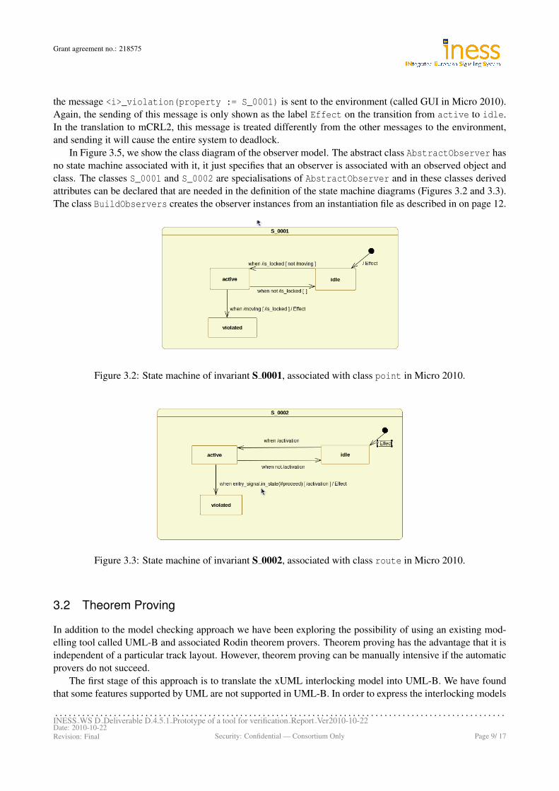
Figure 3.3: State machine of invariant S 0002, associated with class route in Micro 2010.
3.2 Theorem Proving
In addition to the model checking approach we have been exploring the possibility of using an existing mod-elling tool called UML-B and associated Rodin theorem provers. Theorem proving has the advantage that it isindependent of a particular track layout. However, theorem proving can be manually intensive if the automaticprovers do not succeed.
The first stage of this approach is to translate the xUML interlocking model into UML-B. We have foundthat some features supported by UML are not supported in UML-B. In order to express the interlocking models
. . . . . . . . . . . . . . . . . . . . . . . . . . . . . . . . . . . . . . . . . . . . . . . . . . . . . . . . . . . . . . . . . . . . . . . . . . . . . . . . . . . . . . . . . . . . . . . . . . . .INESS WS D Deliverable D.4.5.1 Prototype of a tool for verification Report Ver2010-10-22Date: 2010-10-22Revision: Final Security: Confidential — Consortium Only Page 9/ 17

Grant agreement no.: 218575
Figure 3.4: State machine of invariant S 0002a, associated with class route in Micro 2010.
Figure 3.5: Class diagram of the safety invariant model for Micro 2010 (called ObserverModel.uml).
in UML-B we have added new features to correspond to the ones used in the UML version of the interlockingmodels. The new version (UML-B version 2.0.0), incorporating these new features, is publicly available andwill be released via the Rodin update site. The tool can be installed by following the instructions on the Event-Bweb-site1,2. Work is still in progress to provide an automatic translation from interlocking xUML models toUML-B.
The modelling tool UML-B is developed at the University of Southampton. The Rodin platform is devel-oped jointly between Systerel (URL: www.systerel.fr), University of Southampton, Heinrich-Heine Univer-sity (Dusseldorf) and ETH Zurich.
1http://www.event-b.org/platform.html2http://www.event-b.org/plugins.html
. . . . . . . . . . . . . . . . . . . . . . . . . . . . . . . . . . . . . . . . . . . . . . . . . . . . . . . . . . . . . . . . . . . . . . . . . . . . . . . . . . . . . . . . . . . . . . . . . . . .INESS WS D Deliverable D.4.5.1 Prototype of a tool for verification Report Ver2010-10-22Date: 2010-10-22Revision: Final Security: Confidential — Consortium Only Page 10/ 17

Grant agreement no.: 218575
Section 4 — PROTOTYPE
4.1 Tool chain overview
Figure 4.1 gives a diagrammatic overview of the tool chain that makes up the prototype. Square boxes denotesoftware tools, ellipses denote data. Below we give a brief description of each of these elements.
Figure 4.1: Tool chain diagram.
. . . . . . . . . . . . . . . . . . . . . . . . . . . . . . . . . . . . . . . . . . . . . . . . . . . . . . . . . . . . . . . . . . . . . . . . . . . . . . . . . . . . . . . . . . . . . . . . . . . .INESS WS D Deliverable D.4.5.1 Prototype of a tool for verification Report Ver2010-10-22Date: 2010-10-22Revision: Final Security: Confidential — Consortium Only Page 11/ 17

Grant agreement no.: 218575
4.1.1 Artisan to XMI
The xUML interlocking models are created in Artisan Studio. The translation from xUML to mCRL2, however,requires the xUML models to be provided in the XMI format. We have created a software tool that generatesXMI from the Artisan export files of the xUML interlocking model. This tool was developed by LaQuSo.
4.1.2 Translation from xUML to mCRL2
We describe the input and output of the automated translation module, and give a short description of the modeltransformations involved in the translation. The automated translation tool was developed by LaQuSo andYork.
Input: Interlocking model
The interlocking model is an xUML model which specifies the behaviour of an interlocking, for example, Micro2010.
Input: Track layout
The track layout for which the interlocking xUML model is to be instantiated is defined in a file using a specifiedsyntax. For example, the following lines define the simple track layout in Figure 4.2:
tracks := #[t1, t2, t3];points := #[p1];signals := #[s1];routes := #[(r1, [t1, t2], [], [p1], s1),
(r2, [t1, t3], [p1], [], s1)];
s1
t1
t3
t2
p1
r2
r1
Figure 4.2: Simple track layout.
An interlocking model and a track layout together define an interlocking model instance.
Input: Safety invariant model
The safety invariant model is an xUML model that defines invariants as state machines as described in Sec-tion 3.1.2.
Input: Safety invariant instance
This is a file specifying which safety invariants should be verified in the model instance resulting from theinterlocking model and the track layout. These safety invariant instances are specified using the same syntax asthe in the track layout. For example, the following lines specify that the invariant S 0001 should be instantiatedfor the object p1 of type point, and the invariant S 0002 should be instantiated for objects r1 and r2 of typeroute.
. . . . . . . . . . . . . . . . . . . . . . . . . . . . . . . . . . . . . . . . . . . . . . . . . . . . . . . . . . . . . . . . . . . . . . . . . . . . . . . . . . . . . . . . . . . . . . . . . . . .INESS WS D Deliverable D.4.5.1 Prototype of a tool for verification Report Ver2010-10-22Date: 2010-10-22Revision: Final Security: Confidential — Consortium Only Page 12/ 17

Grant agreement no.: 218575
S_0001_instances := #[(p1,point)];S_0002_instances := #[(r1,route),(r2,route)];
Currently, only one invariant per object can be verified in a model instance. That is, if one wants to verifyboth S 0002 and S 0002a for the route object r1, then this must be done in separate runs of the prototype.
Output: Formal model
The output of the automated translation is a formal specification in the mCRL2 specification language. Thisformal specification combines the interlocking xUML model and the safety invariants in such a way that safetyviolations can be found by using the deadlock detection functionality of the model checking tools.
Model transformation: from UML to mCRL2
The automated translation is implemented using the Eclipse-based model transformation tool set called Epsilon.The translation consists of two steps. In step 1, the input models and files are transformed to an internal modelin which the model data has been restructured and/or augmented in a way that facilitates the generation ofmCRL2 code. In step 2, the mCRL2 code is generated from the internal model. The model transformation ofstep 1 consists of several substeps. First the generic UML models are translated, which creates the classes ofthe internal model. This first step, in particular, includes parsing the actions and expressions on state machinetransitions. Second, the files specifying the track layout and safety invariant instances are used to create objectsand instantiate attributes, associations and actions. Third, the internal model is augmented with data that allowseasy access to the data that is needed for the generation of mCRL2 code in step 2.
4.1.3 Verification using model checking tools
The model checking tools take as input the mCLR2 model generated by the translation process. Using symbolicmethods (cf. [1]), all possible states of the model are explored and it is checked whether any of these states is adeadlock state, i.e. a state from which no further progress is possible.
Due to the encoding of the safety invariant in the translation step a deadlock indicates that the invariant doesnot hold. Furthermore, if deadlocks are absent the encoding guarantees that the safety invariant is valid. In casea deadlock is found, the tools will produce an execution trace (i.e. a sequence of actions) from the initial stateof the system to a deadlock state. This execution trace can be used to diagnose why the safety invariant doesnot hold. The execution trace is provided in plain-text.
The mCRL2 model checking toolset is developed at the Eindhoven University of Technology (LaQuSomember). The LTSmin symbolic model checker is developed at the University of Twente (LaQuSo member).
4.1.4 Trace visualisation
An execution trace provided by the model checking tools is a sequence of actions in the translated mCRL2model, hence it is not expressed in terms of the xUML model that was used to specify the model. In order topresent the results at the level of abstraction of the user, we have created a tool that visualises traces as UMLmessage sequence diagrams.
This trace visualisation tool is implemented using the Epsilon tool set and the UML modelling tool Papyrus.Basically, the generation of the trace visualisation occurs in two steps. In the first step, the text file representingthe execution trace from the model checking tool is parsed, and an input model that can be read by the Epsilontool is generated. In the second step, a model transformation using the Epsilon tool is triggered, where thepreviously generated model is used to generated a graphical UML message sequence diagram which can bedisplayed in Papyrus.
. . . . . . . . . . . . . . . . . . . . . . . . . . . . . . . . . . . . . . . . . . . . . . . . . . . . . . . . . . . . . . . . . . . . . . . . . . . . . . . . . . . . . . . . . . . . . . . . . . . .INESS WS D Deliverable D.4.5.1 Prototype of a tool for verification Report Ver2010-10-22Date: 2010-10-22Revision: Final Security: Confidential — Consortium Only Page 13/ 17

Grant agreement no.: 218575
Figure 4.3 presents a partial diagram produced by the automated trace visualisation. (Due to the size of thesequence, only the initial part is shown.) The sequence diagram consists of vertical lines that correspond to thenames of the objects in the xUML model. In this particular example, it consists of: Environment, RailYard,Signal s1, Point p1, Tracks t1, t2, t3 and IL. The execution of the system is represented by message actions,which correspond to the messages being exchanged between the object components of the system. The notionof time for the system execution flows from the top of the figure downwards. In other words, as the systemprogresses, the messages exchanged start appearing downwards.
Figure 4.3: Example of a generated trace for a property.
The trace visualisation tool is developed at the University of York.
4.1.5 How to use the tool
In the current prototype, the tool is implemented inside the open-source Eclipse environment. It is implementedas different plugins developed for this tool, where several buttons are provided for the user to trigger the verifi-cation of specific properties. By pressing a button, the user can verify the current input xUML model that wastranslated (Micro 2010 in this case) from Artisan Studio for the desired track layout and safety invariants.
The tool allows for the user to modify the track layout as desired (see Figure 4.4), and provides a built-insyntax checker that ensures that the user is inputting a well-formed track layout specification. Once a scenariohas been specified, the user can press a button, or select a menu option, to trigger the verification (see red circlesin Figure 4.4). If a safety invariant was found not to hold, the verification tool will automatically generate avisualised trace and present it to the user. Otherwise, it will simply tell the user that the safety invariants havebeen verified.
. . . . . . . . . . . . . . . . . . . . . . . . . . . . . . . . . . . . . . . . . . . . . . . . . . . . . . . . . . . . . . . . . . . . . . . . . . . . . . . . . . . . . . . . . . . . . . . . . . . .INESS WS D Deliverable D.4.5.1 Prototype of a tool for verification Report Ver2010-10-22Date: 2010-10-22Revision: Final Security: Confidential — Consortium Only Page 14/ 17

Grant agreement no.: 218575
Figure 4.4: Example of a scenario definition in the prototype.
4.1.6 Prototype CD contents
The abovementioned tools are wrapped in a virtual environment which can be run using the Virtual Box soft-ware package (also provided on the CD). The CD furthermore contains instructions for how to install theprototype, and a number of documents referred to in this report, some of which are not publicly available. Thefollowing lists the entire contents of the CD.
• Virtual Box installation files.
• Disk image (actual prototype) containing:
– Modeling tools: Eclipse and an extended version of the UML editor Papyrus, which is used todisplay visualised traces.
– mCRL2 toolset: provides support for the mCRL2 language and pre-processing of mCRL2 specifi-cations before they are put into the model checker.
– LTSmin toolset: explores the state space of mCRL2 models in a symbolic way and detects dead-locks (also providing traces to these deadlocks).
– Trace visualisation tool.
• Installation instructions.
• Documents-folder containing:
– The Micro 2010 interlocking document.– Article (see bibliography item [6]) on our verification strategy published in the scientific journal
Innovations in Systems and Software Engineering.– Presentation slides (bibliography item [4]) by Crispin de Courcey-Bayley and Markus Schacher of
KnowGravity Inc.
. . . . . . . . . . . . . . . . . . . . . . . . . . . . . . . . . . . . . . . . . . . . . . . . . . . . . . . . . . . . . . . . . . . . . . . . . . . . . . . . . . . . . . . . . . . . . . . . . . . .INESS WS D Deliverable D.4.5.1 Prototype of a tool for verification Report Ver2010-10-22Date: 2010-10-22Revision: Final Security: Confidential — Consortium Only Page 15/ 17

Grant agreement no.: 218575
Section 5 — CONCLUSION
In this deliverable, we have presented a prototype which demonstrates our approach to formal verification ofinterlocking xUML models using the Epsilon model transformation technology and the model checking toolsmCRL2 and LTSmin. This prototype allows the user to verify three different safety invariants on the experi-mental Micro 2010 interlocking model. The prototype comes with a simple user interface which integrates theentire verification tool chain. This tool chain consists of the automated translation from xUML to mCRL2 ofan interlocking model and its safety invariants, the subsequent model checking, and the visualisation of errortraces as UML message sequence diagrams. Our future work includes:
• Extending the automated translation to deal with the Generis interlocking model (produced in the EuroInterlocking project). This is foremost a matter of extending the parser.
• Extending the translation from xUML to target languages other than mCRL2, in particular to UML-B.
• Further investigations into how safety invariants can be expressed and verified.
• Further research and development of model checking tools and techniques in order to be able to verifylarge interlocking models such as Generis.
• Provide a UML-B model of the Micro 2010 interlocking with some safety invariants fully proven.
. . . . . . . . . . . . . . . . . . . . . . . . . . . . . . . . . . . . . . . . . . . . . . . . . . . . . . . . . . . . . . . . . . . . . . . . . . . . . . . . . . . . . . . . . . . . . . . . . . . .INESS WS D Deliverable D.4.5.1 Prototype of a tool for verification Report Ver2010-10-22Date: 2010-10-22Revision: Final Security: Confidential — Consortium Only Page 16/ 17

Grant agreement no.: 218575
Bibliography
[1] Stefan Blom and Jaco van de Pol. Symbolic reachability for process algebras with recursive data types.In Proceedings of Theoretical Aspects of Computing (ICTAC 2008), volume 5160 of Lecture Notes inComputer Science, pages 81–95. Springer, 2008.
[2] Stefan Blom, Jaco van de Pol, and Michael Weber. LTSmin: Distributed and symbolic reachability. InProceedings of Computer Aided Verification, volume 6174 of Lecture Notes in Computer Science, pages354–359. Springer Verlag, 2010. ISSN 0302-9743, ISBN 978-3-642-14294-9.
[3] Crispin de Courcey-Bayley. Expression of test cases in UML. Draft report of deliverable 4.2.1 (date:2010-02-11), available on Myndsphere.
[4] Crispin de Courcey-Bayley and Markus Schacher. Validating safety-critical railways systems. Presentationslides for Software and Systems Quality Conference, Zurich, 2009. Included on CD.
[5] Jan Friso Groote, Aad Mathijssen, Michel A. Reniers, Yaroslav S. Usenko, and Muck van Weerdenburg.The formal specification language mCRL2. In Proceedings of Methods for Modelling Software Systems,,volume 06351 of Dagstuhl Seminar Proceedings, 2007.
[6] Helle Hvid Hansen, Jeroen Ketema, Bas Luttik, MohammadReza Mousavi, and Jaco van de Pol. Towardsmodel checking executable UML specifications in mCRL2. Innovations in Systems and Software Engi-neering, 6:83–90, 2010. Included on CD.
[7] Markus Schacher. Micro interlocking 2010, April 2010. Included on CD.
. . . . . . . . . . . . . . . . . . . . . . . . . . . . . . . . . . . . . . . . . . . . . . . . . . . . . . . . . . . . . . . . . . . . . . . . . . . . . . . . . . . . . . . . . . . . . . . . . . . .INESS WS D Deliverable D.4.5.1 Prototype of a tool for verification Report Ver2010-10-22Date: 2010-10-22Revision: Final Security: Confidential — Consortium Only Page 17/ 17