Embed Size (px)
Citation preview
RESEARCH OF TWO-PHASE ELECTRONIC SYSTEM WITH ORTHOGONAL OUTPUT USING MATRIX CONVERTERS
FOR TWO-PHASE APPLICATION M. Prazenica, P. Sekerak, L. Kalamen, B. Dobrucky
Abstract
The paper deals with two-phase power electronic system with variable orthogonal output for industrial- and transport drives applications. Two-phase electronic system with 90 degrees between phases can be easily created using power electronic converters supplied from battery. Output voltages of them are strongly non-harmonic ones, so they must be pulse-modulated due to requested nearly sinusoidal currents with low total harmonic distortion. Modeling and simulation of two-phase power electronic converters with both R-L and motor load is shown in the paper. The simulation models are created in program Matlab-Simulink. Results of simulation are compared with experimental verification ones.
1 Introduction
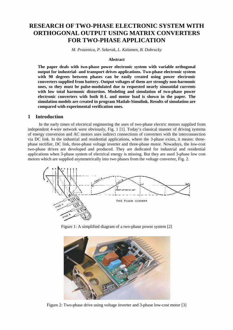
In the early times of electrical engineering the uses of two-phase electric motors supplied from independent 4-wire network were obviously, Fig. 1 [1]. Today’s classical manner of driving systems of energy conversion and AC motors uses indirect connections of converters with the interconnection via DC link. In the industrial and residential applications, where the 3-phase exists, it means: three-phase rectifier, DC link, three-phase voltage inverter and three-phase motor. Nowadays, the low-cost two-phase drives are developed and produced. They are dedicated for industrial and residential applications when 3-phase system of electrical energy is missing. But they are used 3-phase low cost motors which are supplied asymmetrically into two phases from the voltage converter, Fig. 2.
Figure 1: A simplified diagram of a two-phase power system [2]
Figure 2: Two-phase drive using voltage inverter and 3-phase low-cost motor [3]
2 Two-Phase System for Two-Phase Load
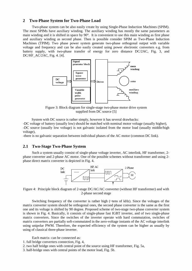
Two-phase system can be also easily create by using Single-Phase Induction Machines (SPIM). The most SPIMs have auxiliary winding. The auxiliary winding has mostly the same parameters as main winding and it is shifted in space by 90°. It is convenient to use this main winding as first phase and auxiliary winding as second phase. Then is possible consider SPIM as Two-Phase Induction Machines (TPIM). Two phase power system generate two-phase orthogonal output with variable voltage and frequency and can be also easily created using power electronic converters e.g. from battery supply, with two-phase transfer of energy for zero distance DC/2AC, Fig. 3, and DC/HF_AC/2AC, Fig. 4. [4].
Figure 3: Block diagram for single-stage two-phase motor drive system supplied from DC source [5]
System with DC source is rather simply, however it has several drawbacks: -DC voltage of battery (usually low) should be matched with nominal motor voltage (usually higher), -DC source (usually low voltage) is not galvanic isolated from the motor load (usually middle/high voltage), -there is no galvanic separation between individual phases of the AC motor (common DC link).
2.1 Two-Stage Two-Phase System
Such a system usually consist of single-phase voltage inverter, AC interlink, HF transformer, 2-phase converter and 2-phase AC motor. One of the possible schemes without transformer and using 2-phase direct matrix converter is depicted in Fig. 4.
Figure 4: Principle block diagram of 2-stage DC/AC/AC converter (without HF transformer) and with 2-phase second stage
Switching frequency of the converter is rather high (~tens of kHz). Since the voltages of the matrix converter system should be orthogonal ones, the second phase converter is the same as the first one and its voltage is shifted by 90 degree. Proposed scheme of two-stage two-phase converter system is shown in Fig. 4. Basically, it consists of single-phase fast IGBT inverter, and of two single-phase matrix converters. Since the switches of the inverter operate with hard commutation, switches of matrix converters are partially soft-commutated in the zero-voltage instants of the AC voltage interlink using unipolar PWM. Therefore, the expected efficiency of the system can be higher as usually by using of classical three-phase inverter.
Each matrix- can be connected as:
1. full bridge converters connection, Fig. 4, 2. two half bridge ones with central point of the source using HF transformer, Fig. 5a, 3. half-bridge ones with central points of the motor load, Fig. 5b.
a) b)
Figure 5: Circuit diagram of half-bridge converters system with a) central points of AC source; b) central points of motor loads
The advantage is then less number of semiconductor devices of the converters (four instead six). Disadvantage of the half-bridge is, of course, double voltage stress of the semiconductor switching elements.
3 PWM Modulation Strategies for Half-Bridge Matrix Converter
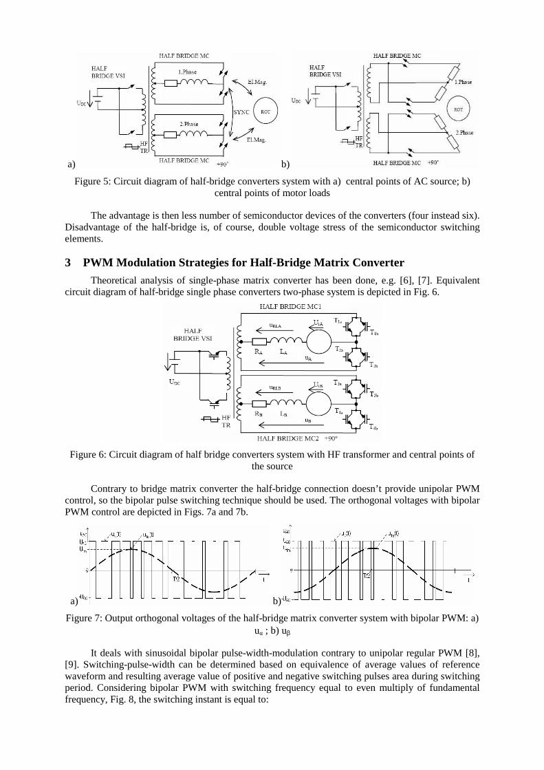
Theoretical analysis of single-phase matrix converter has been done, e.g. [6], [7]. Equivalent circuit diagram of half-bridge single phase converters two-phase system is depicted in Fig. 6.
Figure 6: Circuit diagram of half bridge converters system with HF transformer and central points of the source
Contrary to bridge matrix converter the half-bridge connection doesn’t provide unipolar PWM control, so the bipolar pulse switching technique should be used. The orthogonal voltages with bipolar PWM control are depicted in Figs. 7a and 7b.
a) b)
Figure 7: Output orthogonal voltages of the half-bridge matrix converter system with bipolar PWM: a) uα ; b) uβ
It deals with sinusoidal bipolar pulse-width-modulation contrary to unipolar regular PWM [8], [9]. Switching-pulse-width can be determined based on equivalence of average values of reference waveform and resulting average value of positive and negative switching pulses area during switching period. Considering bipolar PWM with switching frequency equal to even multiply of fundamental frequency, Fig. 8, the switching instant is equal to:

2)(
2
1)( s
DCs
TkS
Ukt +⋅= ∆
, (1)
and the area under sine wave during k-switched interval S∆(k) is:
+⋅−
⋅⋅⋅=∆ )1(
2cos
2cos
2)( k
mk
m
mUkS
ff
fm
πππ
(2)
The total harmonic distortion of the current is given by [14]:
=−
=−=∑
12
12
1
21
2
1
2
I
I
I
II
I
Iν
% 2 ~ 1]- 8.34386)2[(8.34822/ = (3)
Figure 8: PWM with even multiply of f1
Fourier analysis is useful and needed for determination of total harmonic distortion of the phase current of the matrix converter [6, 8, 10]. Switching strategy of one half-bridge matrix converter, based on ‘even’ bipolar PWM, can be explained using Figs. 9a and 9b in greater details.
a) b)
Figure 9: Switching strategy of half bridge converter for a) positive and b) negative half period of operation
It is important and clear visible from these figures that during switching at the end of the period of HF AC supply (n.Ts) the switching losses will be zero due to zero value of commutation voltage. Switching frequency can be set from some kHz for high power applications up to several tens of kHz for low power applications.
4 Two-Phase Induction Motor
Permanent progress in the field of power electronic devices has given a rise to two-phase induction machine (TPIM). These machines have two equal stator windings spatially shifted by 90 degrees. Supply is carried out by two phase converter with currents shifted 90 degrees in time. By means of this supply a waveform of flux density rotating in the air gap, similar to that of the three phase machines, is produced and vibrations and unfavourable noise are thus suppressed [11].
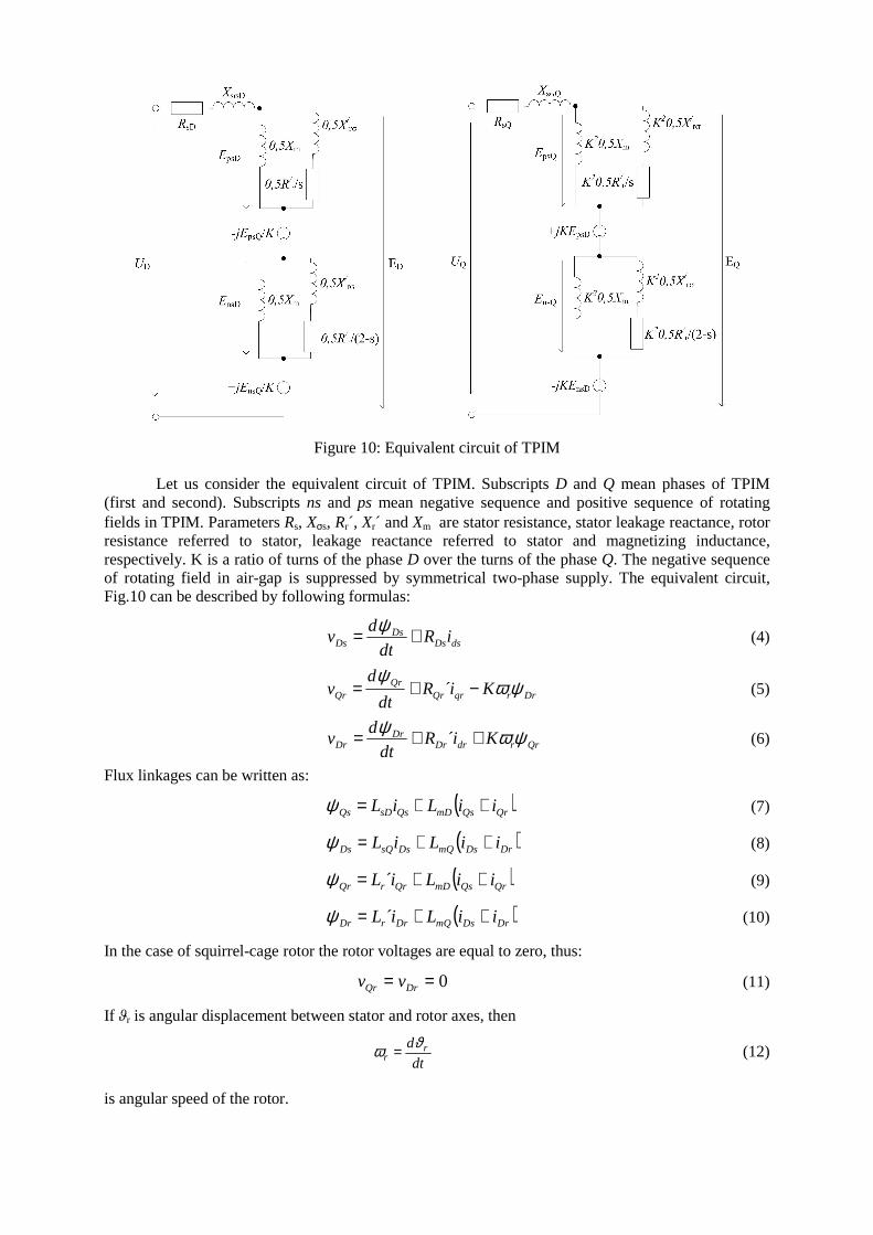
Figure 10: Equivalent circuit of TPIM
Let us consider the equivalent circuit of TPIM. Subscripts D and Q mean phases of TPIM (first and second). Subscripts ns and ps mean negative sequence and positive sequence of rotating fields in TPIM. Parameters Rs, Xσs, Rr´, Xr´ and Xm are stator resistance, stator leakage reactance, rotor resistance referred to stator, leakage reactance referred to stator and magnetizing inductance, respectively. K is a ratio of turns of the phase D over the turns of the phase Q. The negative sequence of rotating field in air-gap is suppressed by symmetrical two-phase supply. The equivalent circuit, Fig.10 can be described by following formulas:
dsDsDs
Ds iRdt
dv += ψ
(4)
DrrqrQrQr
Qr KiRdt
dv ψω
ψ−+= ´ (5)
QrrdrDrDr
Dr KiRdt
dv ψωψ ++= ´ (6)
Flux linkages can be written as:
( )QrQsmDQssDQs iiLiL ++=ψ (7)
( )DrDsmQDssQDs iiLiL ++=ψ (8)
( )QrQsmDQrrQr iiLiL ++= ´ψ (9)
( )DrDsmQDrrDr iiLiL ++= ´ψ (10)
In the case of squirrel-cage rotor the rotor voltages are equal to zero, thus:
0== DrQr vv
(11)
If ϑr is angular displacement between stator and rotor axes, then
dt
d rr
ϑω = (12)
is angular speed of the rotor.
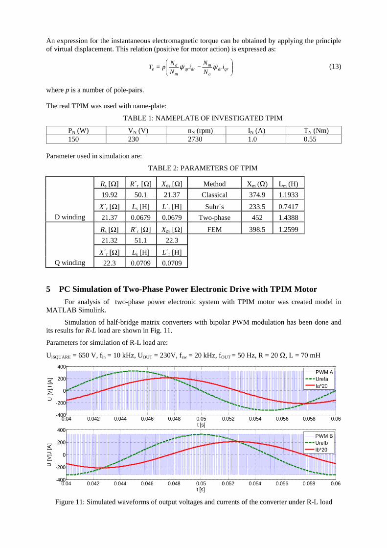
An expression for the instantaneous electromagnetic torque can be obtained by applying the principle of virtual displacement. This relation (positive for motor action) is expressed as:
−= qrdr
a
mdrqr
m
ae i
N
Ni
N
NpT ψψ (13)
where p is a number of pole-pairs.
The real TPIM was used with name-plate:
TABLE 1: NAMEPLATE OF INVESTIGATED TPIM
PN (W) VN (V) nN (rpm) IN (A) TN (Nm) 150 230 2730 1.0 0.55
Parameter used in simulation are:
TABLE 2: PARAMETERS OF TPIM
Rs [Ω] R r [Ω] Xσs [Ω] Method Xm (Ω) Lm (H)
19.92 50.1 21.37 Classical 374.9 1.1933
X r [Ω] Ls [H] L´r [H] Suhr´s 233.5 0.7417
D winding 21.37 0.0679 0.0679 Two-phase 452 1.4388
Rs [Ω] R r [Ω] Xσs [Ω] FEM 398.5 1.2599
21.32 51.1 22.3
X r [Ω] Ls [H] L´r [H]
Q winding 22.3 0.0709 0.0709
5 PC Simulation of Two-Phase Power Electronic Drive with TPIM Motor
For analysis of two-phase power electronic system with TPIM motor was created model in MATLAB Simulink.
Simulation of half-bridge matrix converters with bipolar PWM modulation has been done and its results for R-L load are shown in Fig. 11.
Parameters for simulation of R-L load are:
UiSQUARE = 650 V, fin = 10 kHz, UOUT = 230V, fsw = 20 kHz, fOUT = 50 Hz, R = 20 Ω, L = 70 mH
0.04 0.042 0.044 0.046 0.048 0.05 0.052 0.054 0.056 0.058 0.06-400
-200
0
200
400
t [s]
U [V
],I [A
]
PWM AUrefaIa*20
0.04 0.042 0.044 0.046 0.048 0.05 0.052 0.054 0.056 0.058 0.06-400
-200
0
200
400
t [s]
U [V
],I [A
]
PWM BUrefbIb*20
Figure 11: Simulated waveforms of output voltages and currents of the converter under R-L load
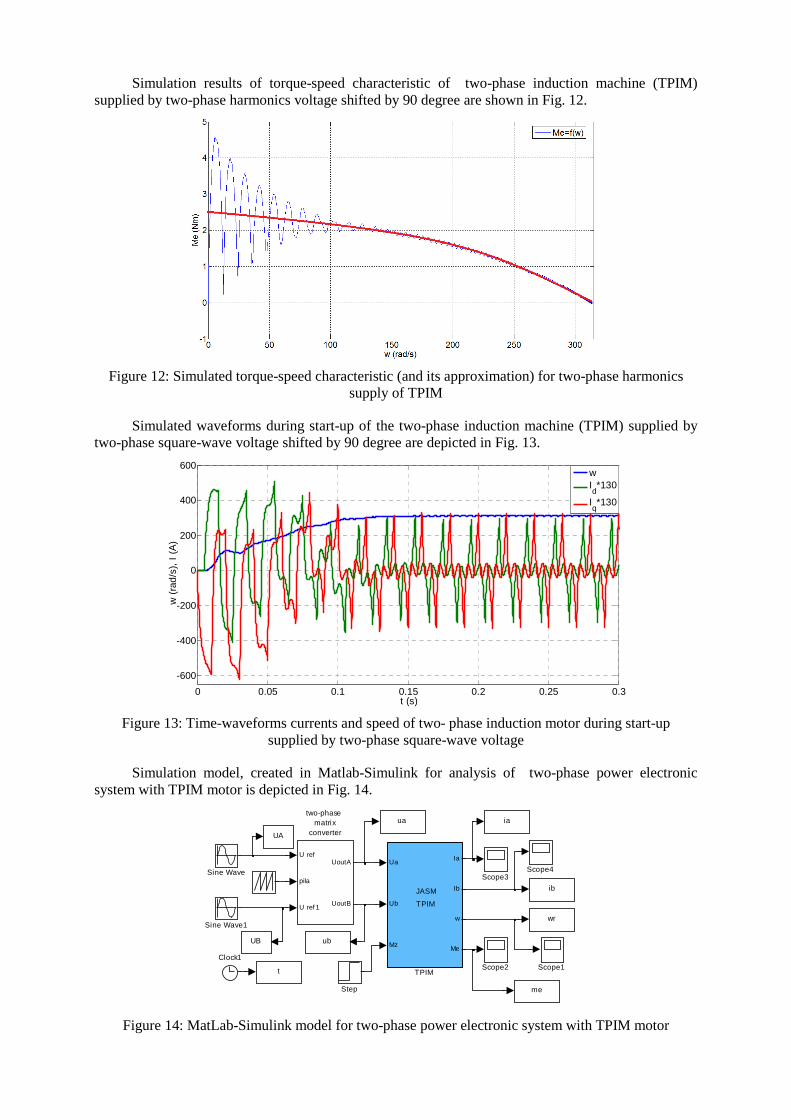
Simulation results of torque-speed characteristic of two-phase induction machine (TPIM) supplied by two-phase harmonics voltage shifted by 90 degree are shown in Fig. 12.
Figure 12: Simulated torque-speed characteristic (and its approximation) for two-phase harmonics supply of TPIM
Simulated waveforms during start-up of the two-phase induction machine (TPIM) supplied by two-phase square-wave voltage shifted by 90 degree are depicted in Fig. 13.
0 0.05 0.1 0.15 0.2 0.25 0.3
-600
-400
-200
0
200
400
600
t (s)
w (
rad/
s),
I (A
)
wId*130
Iq*130
Figure 13: Time-waveforms currents and speed of two- phase induction motor during start-up supplied by two-phase square-wave voltage
Simulation model, created in Matlab-Simulink for analysis of two-phase power electronic system with TPIM motor is depicted in Fig. 14.
U ref
pila
U ref 1
UoutA
UoutB
two-phase matrix
converter
UB
ib
me
UA
iaua
wr
t
ub
Ua
Ub
Mz
Ia
Ib
w
Me
JASM
TPIM
TPIM
Step
Sine Wave1
Sine Wave Scope4Scope3
Scope2 Scope1Clock1
Figure 14: MatLab-Simulink model for two-phase power electronic system with TPIM motor
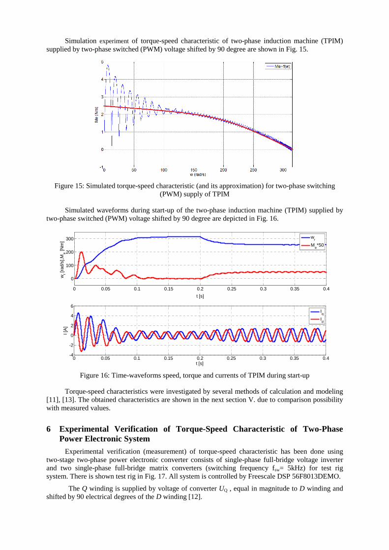
Simulation experiment of torque-speed characteristic of two-phase induction machine (TPIM) supplied by two-phase switched (PWM) voltage shifted by 90 degree are shown in Fig. 15.
Figure 15: Simulated torque-speed characteristic (and its approximation) for two-phase switching (PWM) supply of TPIM
Simulated waveforms during start-up of the two-phase induction machine (TPIM) supplied by two-phase switched (PWM) voltage shifted by 90 degree are depicted in Fig. 16.
0 0.05 0.1 0.15 0.2 0.25 0.3 0.35 0.4
0
100
200
300
t [s]
wr [r
ad/s
],Me [N
m]
wr
Me*50
0 0.05 0.1 0.15 0.2 0.25 0.3 0.35 0.4-4
-2
0
2
4
6
t [s]
I [A
]
Iq
Id
Figure 16: Time-waveforms speed, torque and currents of TPIM during start-up
Torque-speed characteristics were investigated by several methods of calculation and modeling [11], [13]. The obtained characteristics are shown in the next section V. due to comparison possibility with measured values.
6 Experimental Verification of Torque-Speed Characteristic of Two-Phase Power Electronic System
Experimental verification (measurement) of torque-speed characteristic has been done using two-stage two-phase power electronic converter consists of single-phase full-bridge voltage inverter and two single-phase full-bridge matrix converters (switching frequency fsw= 5kHz) for test rig system. There is shown test rig in Fig. 17. All system is controlled by Freescale DSP 56F8013DEMO.
The Q winding is supplied by voltage of converter UQ , equal in magnitude to D winding and shifted by 90 electrical degrees of the D winding [12].
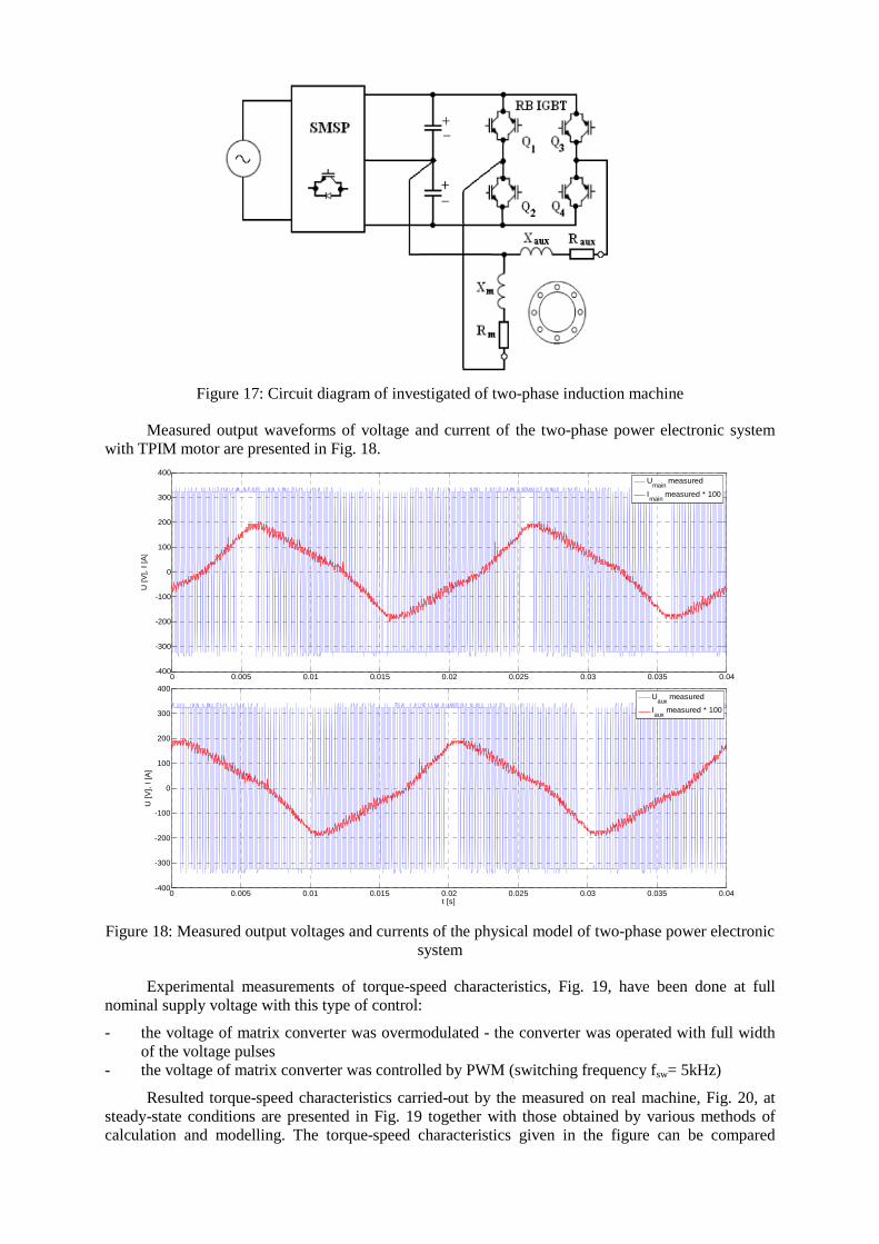
Figure 17: Circuit diagram of investigated of two-phase induction machine
Measured output waveforms of voltage and current of the two-phase power electronic system with TPIM motor are presented in Fig. 18.
0 0.005 0.01 0.015 0.02 0.025 0.03 0.035 0.04-400
-300
-200
-100
0
100
200
300
400
t [s]
U [
V],
I [A
]
Umain
measured
Imain
measured * 100
0 0.005 0.01 0.015 0.02 0.025 0.03 0.035 0.04-400
-300
-200
-100
0
100
200
300
400
t [s]
U [V
], I
[A]
Uaux
measured
Iaux
measured * 100
Figure 18: Measured output voltages and currents of the physical model of two-phase power electronic system
Experimental measurements of torque-speed characteristics, Fig. 19, have been done at full nominal supply voltage with this type of control:
- the voltage of matrix converter was overmodulated - the converter was operated with full width of the voltage pulses
- the voltage of matrix converter was controlled by PWM (switching frequency fsw= 5kHz)
Resulted torque-speed characteristics carried-out by the measured on real machine, Fig. 20, at steady-state conditions are presented in Fig. 19 together with those obtained by various methods of calculation and modelling. The torque-speed characteristics given in the figure can be compared
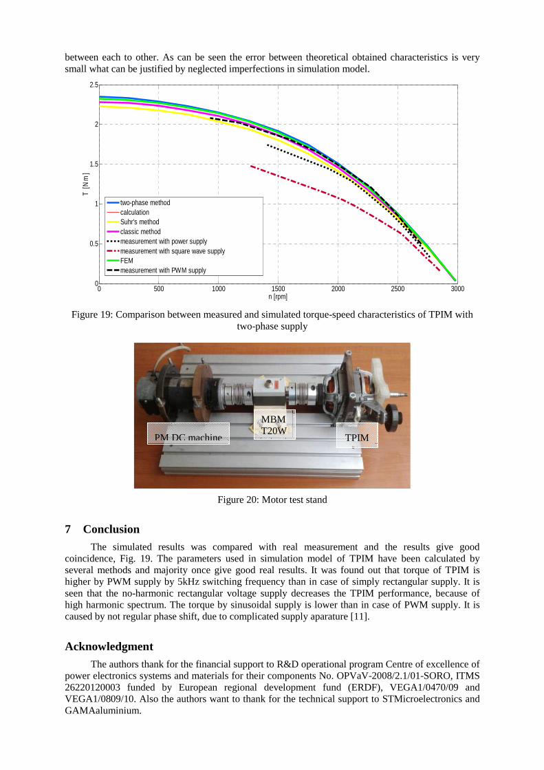
between each to other. As can be seen the error between theoretical obtained characteristics is very small what can be justified by neglected imperfections in simulation model.
0 500 1000 1500 2000 2500 30000
0.5
1
1.5
2
2.5
n [rpm]
T [
Nm
]
two-phase methodcalculationSuhr's methodclassic methodmeasurement with power supply measurement with square wave supply FEMmeasurement with PWM supply
Figure 19: Comparison between measured and simulated torque-speed characteristics of TPIM with two-phase supply
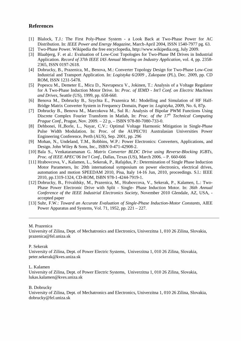
Figure 20: Motor test stand
7 Conclusion
The simulated results was compared with real measurement and the results give good coincidence, Fig. 19. The parameters used in simulation model of TPIM have been calculated by several methods and majority once give good real results. It was found out that torque of TPIM is higher by PWM supply by 5kHz switching frequency than in case of simply rectangular supply. It is seen that the no-harmonic rectangular voltage supply decreases the TPIM performance, because of high harmonic spectrum. The torque by sinusoidal supply is lower than in case of PWM supply. It is caused by not regular phase shift, due to complicated supply aparature [11].
Acknowledgment
The authors thank for the financial support to R&D operational program Centre of excellence of power electronics systems and materials for their components No. OPVaV-2008/2.1/01-SORO, ITMS 26220120003 funded by European regional development fund (ERDF), VEGA1/0470/09 and VEGA1/0809/10. Also the authors want to thank for the technical support to STMicroelectronics and GAMAaluminium.
PM DC machine TPIM
MBM T20W
References
[1] Blalock, T.J.: The First Poly-Phase System - a Look Back at Two-Phase Power for AC
Distribution. In: IEEE Power and Energy Magazine, March-April 2004, ISSN 1540-7977 pg. 63. [2] Two-Phase Power. Wikipedia the free encyclopedia, http://www.wikipedia.org, July 2009. [3] Blaabjerg, F. et al.: Evaluation of Low-Cost Topologies for Two-Phase IM Drives in Industrial
Application. Record of 37th IEEE IAS Annual Meeting on Industry Application, vol. 4, pp. 2358-2365, ISSN 0197-2618.
[4] Dobrucky, B., Prazenica, M., Benova, M.: Converter Topology Design for Two-Phase Low-Cost Industrial and Transport Application. In: Logistyka 6/2009 , Zakopane (PL), Dec. 2009, pp. CD ROM, ISSN 1231-5478.
[5] Popescu M., Demeter E., Micu D., Navrapescu V., Jokinen, T.: Analysis of a Voltage Regulator for A Two-Phase Induction Motor Drive. In: Proc. of IEMD - Int'l Conf. on Electric Machines and Drives, Seattle (US), 1999, pp. 658-660.
[6] Benova M., Dobrucky B., Szychta E., Prazenica M.: Modelling and Simulation of HF Half-Bridge Matrix Converter System in Frequency Domain, Paper in: Logistyka, 2009, No. 6, 87p.
[7] Dobrucky B., Benova M., Marcokova M., Sul R.: Analysis of Bipolar PWM Functions Using Discrete Complex Fourier Transform in Matlab, In: Proc. of the 17th Technical Computing Prague Conf., Prague, Nov. 2009. – 22 p, – ISBN 978-80-7080-733-0.
[8] Dehbonei, H.,Borle, L., Nayar, C.V.: Optimal Voltage Harmonic Mitigation in Single-Phase Pulse Width Modulation. In: Proc. of the AUPEC'01 Australasian Universities Power Engineering Conference, Perth (AUS), Sep. 2001, pp. 296
[9] Mohan, N., Undeland, T.M., Robbins, W.P.: Power Electronics: Converters, Applications, and Design. John Wiley & Sons, Inc., ISBN 0-471-42908-2.
[10] Bala S., Venkataramanan G. Matrix Converter BLDC Drive using Reverse-Blocking IGBTs, Proc. of IEEE APEC’06 Int’l Conf., Dallas, Texas (US), March 2006. – P. 660-666
[11] Hrabovcova, V., Kalamen, L., Sekerak, P., Rafajdus, P.: Determination of Single Phase Induction Motor Parameters, In: 20th international symposium on power electronics, electrical drives, automation and motion SPEEDAM 2010, Pisa, Italy 14-16 Jun, 2010, proceedings. S.l.: IEEE 2010, pp.1319-1324, CD-ROM, ISBN 978-1-4244-7919-1.
[12] Dobrucky, B., Frivaldsky, M., Prazenica, M., Hrabovcova, V., Sekerak, P., Kalamen, L.: Two-Phase Power Electronic Drive with Split - Single- Phase Induction Motor. In: 36th Annual Conference of the IEEE Industrial Electronics Society, November 2010 Glendale, AZ, USA, - accepted paper
[13] Suhr, F.W.: Toward an Accurate Evaluation of Single-Phase Induction-Motor Constants, AIEE Power Apparatus and Systems, Vol. 71, 1952, pp. 221 – 227.
M. Prazenica University of Zilina, Dept. of Mechatronics and Electronics, Univerzitna 1, 010 26 Zilina, Slovakia, [email protected] P. Sekerak University of Zilina, Dept. of Power Electric Systems, Univerzitna 1, 010 26 Zilina, Slovakia, [email protected] L. Kalamen University of Zilina, Dept. of Power Electric Systems, Univerzitna 1, 010 26 Zilina, Slovakia, [email protected] B. Dobrucky University of Zilina, Dept. of Mechatronics and Electronics, Univerzitna 1, 010 26 Zilina, Slovakia, [email protected]