Embed Size (px)
Citation preview
A guide
to the selection of cable types in accordance with the recommendations of
BS 8519:2010“Selection and installation
of fire-resistant power and control cable systems
for life safety and fire-fighting applications -
Code of practice”
by T.L. Journeaux
FP Guide to BS 8519:2010
A brand of the

Contents
2
BS 8519:2010 “SELECTION AND INSTALLATION OF FIRE-RESISTANT CABLES FOR LIFE SAFETY AND FIRE FIGHTING APPLICATIONS”
Printed August 2010
Introduction
BS 7346-6 and the 2006 edition of Approved Document B
Fire survival times
Cable selection and test methods
Cable sizing and the effects of fire temperature
Guidance on installation practice
Protection of High Voltage supply cables
Key Applications
Key issues for specifiers
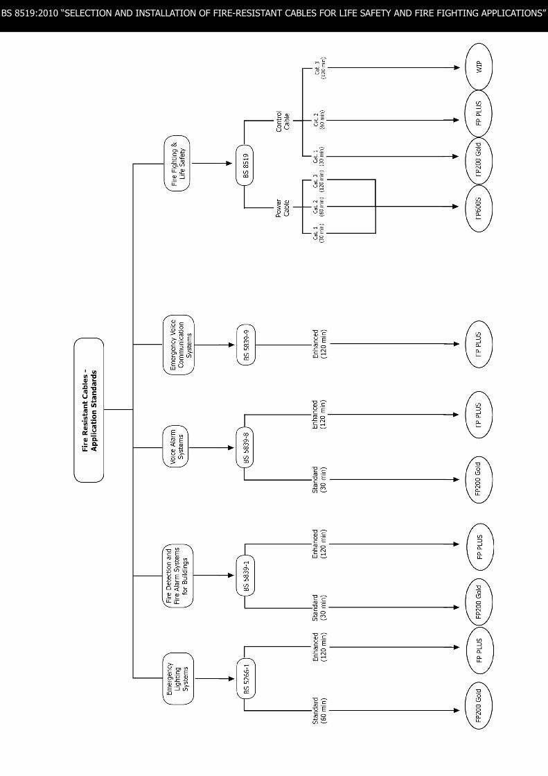
Fire resistant cables - application standards
Guidance notes
Introduction
BS 7346-6 and the 2006 edition of Approved Document B
Fire survival times
Cable selection and test methods
Cable sizing and the effects of fire temperature
Guidance on installation practice
Protection of High Voltage supply cables
Key Applications
Key issues for specifiers
Fire resistant cables - application standards
Guidance notes
Page 3
Page 3
Page 3
Page 4
Page 5
Page 5
Page 5
Page 6
Page 6
Page 7
page 8
Reviewed and reprinted April 2014
3
BS 8519:2010 “SELECTION AND INSTALLATION OF FIRE-RESISTANT CABLES FOR LIFE SAFETY AND FIRE FIGHTING APPLICATIONS”
Introduction
BS 8519 is a new Code of practice giving guidance and recommendations for the “Selection and installation of fire-resistant power and control cable systems for life safety and fire-fighting applications”:-
BS 8519 was published in February 2010 and became effective immediately.
Relationship between BS 7346-6 and the 2006 edition of Approved Document B of The Building Regulations
BS 8519:2010 is a complete revision of BS 7346-6:2005 “Components for smoke and heat control systems - Part 6: Specification for cable systems” which has been withdrawn. The new CoP has an expanded scope to all life safety and fire-fighting systems except fire detection, fire alarm and emergency lighting. It includes much new and revised technical guidance relevant to the selection and installation of fire-resistant cables. The cable test method previously given in Annex B of BS 7346-6 has previously been published separately as BS 8491.
For large and complex buildings, Approved Document B (5.38) refers to BS 7346-6 for guidance on the selection of cables that need to operate for an extended period during a fire. This guidance is now found in BS 8519.
Fire Survival Times
Three fire survival times are recognised in BS 8519, according to the specific life safety or fire-fighting application.
For life safety systems it is recommended that the system should be capable of remaining operational for 60 minutes in large and/or complex buildings and 30 minutes in others.
For fire fighting systems it is recommended that the system should be capable of servicing active systems for 60 minutes or 120 minutes depending on the specific application.
The fire survival times are allocated categories for ease of reference:
> Category 1 - 30 minute fire survival time > Category 2 - 60 minute fire survival time> Category 3 - 120 minute fire survival time
> It specifically covers high rise and complex buildings and recognises that the fire engineered solutions developed for such buildings require a high level of performance from components of the building services including electrical supplies.> It is intended for designers, contractors, regulators and enforcers, fire authorities and inspectors.> It identifies electrical loads defined as life safety or fire-fighting and recommends minimum categories for particular applications.> It identifies three categories of circuits (Categories 1, 2 and 3) with fire survival times of 30 min, 60 min and 120 min.> It identifies appropriate cable tests for the categories.> It aims to ensure that the level of circuit integrity of the cables is not compromised by other electrical system components.> It does NOT give recommendations for the wiring of fire detection and fire alarm systems which are covered by BS 5839-1, BS 5839-6, BS 5839-8 and BS 5839-9 or emergency lighting systems covered by BS 5266-1.
5
BS 8519:2010 “SELECTION AND INSTALLATION OF FIRE-RESISTANT CABLES FOR LIFE SAFETY AND FIRE FIGHTING APPLICATIONS”
4
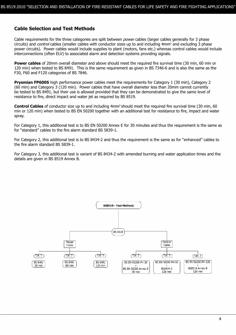
Cable Selection and Test Methods
Cable requirements for the three categories are split between power cables (larger cables generally for 3 phase circuits) and control cables (smaller cables with conductor sizes up to and including 4mm2 and excluding 3 phase power circuits). Power cables would include supplies to plant (motors, fans etc.) whereas control cables would include interconnections (often ELV) to associated alarm and detection systems providing signals.
Power cables of 20mm overall diameter and above should meet the required fire survival time (30 min, 60 min or 120 min) when tested to BS 8491. This is the same requirement as given in BS 7346-6 and is also the same as the F30, F60 and F120 categories of BS 7846.
Prysmian FP600S high performance power cables meet the requirements for Category 1 (30 min), Category 2 (60 min) and Category 3 (120 min). Power cables that have overall diameter less than 20mm cannot currently be tested to BS 8491, but their use is allowed provided that they can be demonstrated to give the same level of resistance to fire, direct impact and water jet as required by BS 8519.
Control Cables of conductor size up to and including 4mm2 should meet the required fire survival time (30 min, 60 min or 120 min) when tested to BS EN 50200 together with an additional test for resistance to fire, impact and water spray.
For Category 1, this additional test is to BS EN 50200 Annex E for 30 minutes and thus the requirement is the same as for “standard” cables to the fire alarm standard BS 5839-1.
For Category 2, this additional test is to BS 8434-2 and thus the requirement is the same as for “enhanced” cables to the fire alarm standard BS 5839-1.
For Category 3, this additional test is variant of BS 8434-2 with amended burning and water application times and the details are given in BS 8519 Annex B.
5
BS 8519:2010 “SELECTION AND INSTALLATION OF FIRE-RESISTANT CABLES FOR LIFE SAFETY AND FIRE FIGHTING APPLICATIONS”
Cable sizing for the effects of fire temperature
The conductor temperature of a cable in a fire will rise above the maximum conductor temperature upon which tabulated current rating and voltage drop data is based. This will have implications for voltage drop and the effects of fault currents, which may be significant in certain applications.
Annexes of BS 8519 give guidance on the review of these factors together with a recommendation that the advice of the cable manufacturer should be sought.
The content of these informative annexes is based upon Prysmian guidance notes which are included in this booklet.
Sizing of circuit protective conductors (CPCs) is also addressed in BS 8519. Where supplementing of the cable armour with a separate external CPC is necessary to achieve the correct earth fault impedance, it is recommended that the external CPC should be not less than 25% of the cross-sectional area of the phase conductor.
Guidance on installation practice
In order to ensure that the circuit integrity of the installed cables is not compromised by other components of the system such as fixings, containment system, glands and joints, BS 8519 gives some detailed recommendations on cable installation practice. Joints, of course, should be avoided unless absolutely essential.
It is recommended that cable fixings and fixing centres should be in accordance with the cable manufacturer’s recommendations. Such recommendations for Prysmian FP cables are given in the appropriate cable data sheet.
It is recommended that robust armoured cables (such as those meeting BS 8491 and BS 7846) are installed either fixed direct to the building structure or on a cable management system. In cases where additional mechanical protection is required, installation on a cable management system or in a containment system is recommended. Any such cable management systems are required to maintain their function in the presence of the same flame, mechanical impact and water jet conditions and for the same time period as required for the cables, although no specific tests are given as they are still in the process of development. Manufacturers of fire rated cable management systems should be consulted regarding the design and specification of compliant systems. (See table 12 of guidance note no.1 wiring regs BS 7671).
Protection of High Voltage Supply Cables
For security of supply, BS 8519 recommends that mains supply cables serving life safety and fire fighting systems should directly enter the fire rated switch rooms and not pass through the building. However, it is recognised that in certain instances such cables may have to be routed through the building, in which case they should be fire protected by a protective system for the appropriate survival time.
As suitable HV cables with intrinsic resistance to fire are not available, normal cables (e.g. BS 7835) should be used with appropriate protection. Protection may be achieved by installation of the cable within a concrete trench with concrete cover, routing within a dedicated shaft or void of the appropriate fire rating, or enclosure throughout their length by passive fire protection material giving 120 minute fire resistance together with the capability of withstanding the effects of a water jet after such exposure. Certain high performance systems based on composite panels of fibre reinforced cement bonded to steel sheets are claimed to be suitable.
BS 8519 recommends that the performance of the enclosure should be assessed in accordance with BS EN 1366-5:2003 for integrity and thermal insulation under conditions of fire outside the duct. In order to ensure no adverse effect on the cable, the measured temperature inside the duct should not exceed the initial temperature by more than 180 oC. Manufacturers of fire rated systems suitable for cable protection should be consulted regarding the design of compliant systems.
Restriction of the temperature rise within the fire protective system to 180oC will ensure that XLPE insulated cables to BS 7835 will operate for the required 120 minutes.
6
BS 8519:2010 “SELECTION AND INSTALLATION OF FIRE-RESISTANT CABLES FOR LIFE SAFETY AND FIRE FIGHTING APPLICATIONS”
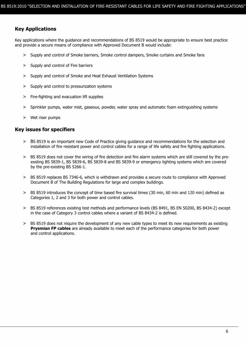
Key Applications
Key applications where the guidance and recommendations of BS 8519 would be appropriate to ensure best practice and provide a secure means of compliance with Approved Document B would include:
Key issues for specifiers
> Supply and control of Smoke barriers, Smoke control dampers, Smoke curtains and Smoke fans
> Supply and control of Fire barriers
> Supply and control of Smoke and Heat Exhaust Ventilation Systems
> Supply and control to pressurization systems
> Fire-fighting and evacuation lift supplies
> Sprinkler pumps, water mist, gaseous, powder, water spray and automatic foam extinguishing systems
> Wet riser pumps
> BS 8519 is an important new Code of Practice giving guidance and recommendations for the selection and installation of fire resistant power and control cables for a range of life safety and fire fighting applications.
> BS 8519 does not cover the wiring of fire detection and fire alarm systems which are still covered by the pre- exsting BS 5839-1, BS 5839-6, BS 5839-8 and BS 5839-9 or emergency lighting systems which are covered by the pre-existing BS 5266-1. > BS 8519 replaces BS 7346-6, which is withdrawn and provides a secure route to compliance with Approved Document B of The Building Regulations for large and complex buildings.
> BS 8519 introduces the concept of time based fire survival times (30 min, 60 min and 120 min) defined as Categories 1, 2 and 3 for both power and control cables.
> BS 8519 references existing test methods and performance levels (BS 8491, BS EN 50200, BS 8434-2) except in the case of Category 3 control cables where a variant of BS 8434-2 is defined. > BS 8519 does not require the development of any new cable types to meet its new requirements as existing Prysmian FP cables are already available to meet each of the performance categories for both power and control applications.
7
BS 8519:2010 “SELECTION AND INSTALLATION OF FIRE-RESISTANT CABLES FOR LIFE SAFETY AND FIRE FIGHTING APPLICATIONS”

8
BS 8519:2010 “SELECTION AND INSTALLATION OF FIRE-RESISTANT CABLES FOR LIFE SAFETY AND FIRE FIGHTING APPLICATIONS”
A Current ratings and voltage drop for cables in a fire:
When a cable is involved in a fire, the conductor temperature will rise above the maximum conductor temperature upon which the tabulated current rating and voltage drop data given in Prysmian Cables & Systems Ltd. data sheets is based.
In carrying a set current, a cable with its conductor temperature at 950 oC will experience a greater temperature rise due to current loading than a cable with its conductor temperature at 90 oC. However, the additional temperature rise due to this factor will be less that 50 oC and is not significant in relation to the temperature rise caused by fire.
The voltage drop at typical fire temperatures will be higher that at 90 oC and this may be significant for certain types of load. Assuming a worst case of the total length of the cable run in the fire, it may be necessary to increase the conductor size as illustrated in the following examples.
Voltage drop calculations for cables in a fire:
The process of calculating voltage drop of a cable is normally straight forward. Tabulated values are multiplied by the length of run and current to be carried, to give the expected voltage drop.
It should be noted that the tabulated values assume that the cable conductor temperature is at its maximum permitted normal operating temperature.
If the cable is involved in a fire, the conductor temperature and hence the resistance would be higher, therefore the voltage drop would be higher.
The problem in determining the voltage drop for a run of cable in a fire is to know the conductor temperature at each point along its length. Therefore assumptions have to be made in calculating what the voltage drop would be.
To illustrate the effect of assuming different lengths of cable being involved in a fire, two sets of examples are given, one based on 5 A and the other based on 200 A load.
Example 1.0:
Assume a 2 core 2.5mm2 FP400 cable carrying 5 A over 50 m.
In normal operation the voltage drop would be:
19 x 0.001 x 5 x 50 = 4.75 V.
Where 19 is the mV/A/m for FP400 2.5mm2 at 90 oC
Example 1.1:
Assume a 2 core 2.5mm2 FP400 cable carrying 5 A over 50 m. Assume 2 m are at 750 oC and the rest of the cable is at 90 oC. Volt drop would be:
(19 x 0.001 x 5 x 48) + (19 x 0.001 x 3.0342 x 5 x 2) = 5.14 V
Example 1.2:
Assume a 2 core 2.5mm2 FP400 cable carrying 5 A over 50 m. Assume all 50 m are at 750 oC. Volt drop would be:
19 x 0.001 x 3.0342 x 5 x 50 = 14.41 V.
Example 2.0:
Assume a 2 core 120mm2 FP600S cable carrying 200 A over 50 m. In normal operation the volt drop would be:
0.42 x 0.001 x 200 x 50 = 4.2 V
Where 0.42 is the mV/A/m for FP600S 120mm2 at 90 oC.
Example 2.1:
Assume a 2 core 120mm2 FP600S cable carrying 200 A over 50 m. Assume 2m are at 750 oC and the rest of the cable is at 90oC. Volt drop would be:
(0.42 x 0.001 x 200 x 48) + (0.42 x 0.001 x 3.0342 x 200 x 2) = 4.45 V.
Example 2.2:
Assume a 2 core 120mm2 FP600S cable carrying 200 A over 50 m. Assume all 50 m are at 750 oC. Volt drop would be:
0.042 x 0.001 x 3.042 x 200 x 5 = 12.74 V
As can be seen from these examples, although the voltage drop has increased from normal operation, with part of a cable or all the cable in a fire, the percentage drop from a 240 V single phase supply does not increase significantly.
This to say : Example 1, would give 1.98%, 2.14% and 6% respectively. Example 2, would give 1.75%, 1.9% and 5.3% respectively.
From these percentage volt drop values, it would seem unlikely that a fire would have a significant effect on most equipment being supplied by the cable, even in the example of the worst case given above.
However if it is required to limit the volt drop to 4% for the example when the whole length of cable is in the fire, e.g. motors running fire fighting water pumps; then the cable sizes in examples 1.2 and 2.2 would have to be
Guidance Notes: As printed in BS 8519:2010

9
Notes...
BS 8519:2010 “SELECTION AND INSTALLATION OF FIRE-RESISTANT CABLES FOR LIFE SAFETY AND FIRE FIGHTING APPLICATIONS”

10
Notes...
BS 8519:2010 “SELECTION AND INSTALLATION OF FIRE-RESISTANT CABLES FOR LIFE SAFETY AND FIRE FIGHTING APPLICATIONS”

11
Notes...
BS 8519:2010 “SELECTION AND INSTALLATION OF FIRE-RESISTANT CABLES FOR LIFE SAFETY AND FIRE FIGHTING APPLICATIONS”

A brand of the
Sales enquiriesTel: 0845 767 8345Fax: 023 8029 5465
UK Technical helplineTel: 0845 767 8345Fax: 023 8029 5002
Prysmian Cables & Systems LimitedChickenhall LaneEastleigh HampshireSO50 6YUUnited Kingdom www.prysmian.co.ukwww.fpcables.co.uk
Overseas sales enquiriesTel: +44 (0) 23 5029 5481Fax: +44 (0) 23 8029 5465
Overseas technicalTel: +44 (0) 23 8029 5481Fax: +44 (0) 23 8029 5002
Information hotlineTel: +44 (0) 23 8029 5029Fax: +44 (0) 23 8029 5437
Should you have any concerns aboutunsafe, non-approved or counterfeitcable, please contact the ACI
Tel: 020 8946 6978Email: [email protected]


![[BS 1041-5-1989] -- Temperature measurement. Guide to selection and use of radiation pyrometers.pdf](https://img.pdfslide.us/doc/110x75/577c77c71a28abe0548d76a6/bs-1041-5-1989-temperature-measurement-guide-to-selection-and-use-of.jpg)