Embed Size (px)
Citation preview
Fourier-transform speckle profilometry:three-dimensional shape measurements of diffuseobjects with large height steps and/or spatiallyisolated surfaces
Mitsuo Takeda and Hirokazu Yamamoto
An interferometric technique for automated profilometry of diffuse objects has been proposed. It isbased on the Fourier-fringe analysis of spatiotemporal specklegrams produced by a wavelength-shiftinterferometer with a laser diode as a frequency-tunable light source. Unlike conventional moir6techniques the proposed technique permits the objects to have discontinuous height steps and/or surfacesspatially isolated from one another. Experimental results are presented that demonstrate the validity ofthe principle.
Key words: Profilometry, interferometry, speckle, Fourier transform.
1. Introduction
Projecting a periodic pattern onto an object andobserving its deformation from a different view anglehas been a common principle for various three-dimensional shape-measurement techniques,' e.g.,moir6 techniques2 and Fourier-transform profilome-try (FTP).3 However, these techniques cannot beapplied to those objects that have discontinuousheight steps and/or spatially isolated surfaces, be-cause the discontinuities and/or the surface isola-tions hinder the unique assignment of fringe ordersfor the moir6 techniques and the unique phase un-wrapping for the FTP. Although one can measure acertain class of such an object by using a light-sectioning technique,4 the shape of the object isrestricted to the one that causes no shadings both inprojection and in observation. This restriction iscommon to all techniques that require a baseline fortriangulation, among which are a laser-triangulationtechniques and a stereo technique (besides the moire,FTP, and light-sectioning techniques mentionedabove). Recently Dresel et al.6 proposed the coher-ence-radar technique and successfully demonstrated
The authors are with the Department of Communication andSystems Engineering, The University of Electro-Communications,1-5-1, Chofugaoka, Chofu, Tokyo 182, Japan.
Received 19 January 1994; revised manuscript received 14 June1994.
0003-6935/94/347829-09$06.00/0.c 1994 Optical Society of America.
its ability to solve all the problems described above.However, because their technique is based on thegeneration of white-light fringes by nulling the opti-cal path differences caused by the height distributionof an object, it requires accurate mechanical move-ment of the object and reference mirror for thecompensation of the optical path differences betweenthe beams from the object surface and the referencemirror. When the object has large height steps, thealignment of the interferometer during the largemovement of the object may become a critical issue.Furthermore the time for the measurement maybecome a problem, because, for the peaks of thewhite-light fringe amplitudes to be detected, theobject needs to be translated over a large distance,say, 5 cm, by steps smaller than the coherencelength of the light sources, say, 2 tim, whichrequires a repetition of more than 25,000 step move-ments of the object. The phase-shift measurementmust be made at each of these step movements.
The purpose of this paper is to propose an alterna-tive technique called Fourier-transform speckle pro-filometry (FTSP), which is based on a combination ofthe Fourier-transform technique for fringe patternanalysis7-9 and wavelength-shift speckle interferom-etry. The technique can measure objects with roughsurfaces with discontinuities and/or isolations.Instead of the incoherent polychromatic light sourcesused in the coherence-radar technique6 and in thedouble-spectral-modulation technique,10 we use a co-herent frequency-tunable laser diode as a light source.
1 December 1994 / Vol. 33, No. 34 / APPLIED OPTICS 7829
In common with the coherence-radar technique andthe double-spectral-modulation technique, the FTSPhas the advantage over conventional triangulationtechniques in that it can measure three-dimensionalshapes of narrow crevices and holes without beingdisturbed by shading caused by large apertures ortriangulation angles. Moreover the FTSP does notrequire any mechanically moving components, suchas a piezoelectric transducer and/or a translationstage that are necessary in the coherence-radar tech-nique6 and in the phase-shifting speckle interferom-etry 1; nor does the FTSP require a rotating analyzerand/or an object translation stage that are needed ina two-wavelength heterodyne speckle interferometer.12
In addition the optical system becomes much simplerthan the double-spectral-modulation technique 0 be-cause the FTSP uses no grating monochromators forspectral modulation. First we describe the principleof our technique. Next we present some experimen-tal results that demonstrate the validity of the prin-ciple. Finally we discuss the relationship betweenthe FTSP and the existing techniques and considerthe limitation of the FTSP.
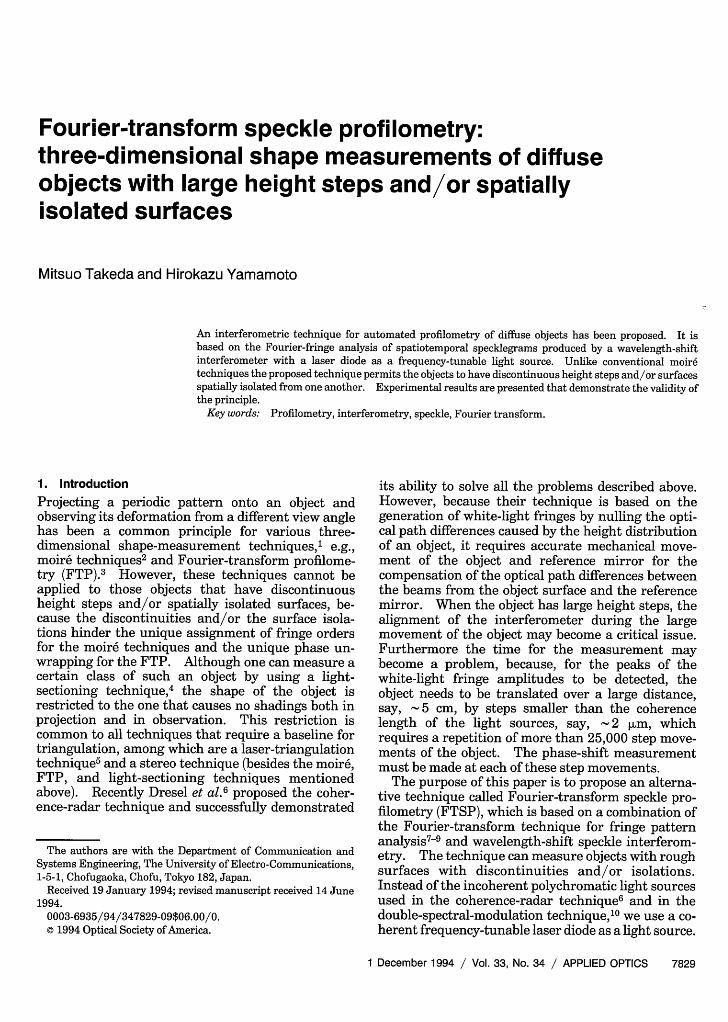
2. PrincipleA schematic illustration of the wavelength-shiftspeckle interferometer is shown in Fig. 1. The con-figuration of the interferometer is similar to that ofthe coherence radar6 except for a few but importantdifferences. First, a laser diode is used as a coherentfrequency-tunable light source. 13 Second, the armsof the interferometer are made to have significantlydifferent optical path lengths. Because a coherentlight source is employed, also note the similarity ofthe interferometer to the one used in conventionalspeckle interferometry.14 However, a crucial feature
LaserDiode
(x,y)
Reference
> Field Lens
TV Camera
Fig. 1. Schematic illustration of a wavelength-shift speckle inter-ferometer. f, focal length of the imaging lens.
of this interferometer is that it can measure theobject shape itself whereas it is the deformation fromthe original shape that is measured by conventionalspeckle interferometry. Referring to Fig. 1, we seethat a collimated beam from the frequency-tunablelight source is divided at a beam splitter (BS) into twobeams. One beam is reflected from a referencemirror back to the beam splitter to serve as areference beam. The other beam is scattered fromthe object surface back to the beam splitter to berecombined with the reference beam. The object isimaged onto an image sensor by a telecentric imagingsystem. More specifically an imaging lens with astop at its rear focal plane forms an image of theobject on the aperture of a field lens. The field lensin turn forms an image of the stop on the aperture ofa TV camera lens. The object image on the apertureof the field lens is relayed by the TV camera lens toform its final image on the image sensor. By thistelecentric imaging system, the lights participating ininterference are restricted to those that propagate inthe direction parallel to the optical axis after beingrecombined by the beam splitter. Telecentric opticspermits the interpretation that the interferometer iscomposed of a great many elementary Michelsoninterferometers, each of which independently formsindividual speckle patterns. By controlling the injec-tion current to the laser diode, we varied the wavenumber k = 27r/X (X is wavelength) of the light sourcequasi-linearly with time t so that
k(t) = att + K(t), ()
where a is a constant and K(t) represents an initialwave number k(0) plus an unavoidable deviation fromperfect linearity. Using this frequency-scanningspeckle interferometer, we have a time-varying speck-legram of the form
g(x, y; t) = a(x, y; t) + b(x, y; t)cos[2k(t)l(x, y)], (2)
where a(x, y; t) and b(x, y; t) are, respectively, a back-ground intensity and a fringe amplitude that unavoid-ably vary with the injection current and l(x, y) is anobject height distribution in terms of the half opticalpath difference between the beams from the objectsurface and the reference mirror; 1(x, y) is shown inFig. 1 with reference to a virtual image of thereference mirror, and it is related to the object heighth(x, y) by
h(x,y) = I(x,y) - lo. (3)
In Eq. (3), lo = 1(xo, yo) is a constant that gives a halfoptical path difference between the beams from thereference mirror and the point at (xo, yo) on the object.The point at (x0, yo) defines the plane of zero levelfrom which the object height is to be measured.Both a microscopic-surface-roughness distributionand a macroscopic-surface-height distribution areincluded in l(x,y) [and hence also in h(x,y)]. We
7830 APPLIED OPTICS / Vol. 33, No. 34 / 1 December 1994
and we have put
fo(x, ) = al(x, y)/r, (4)
+(x, y; t) = 2K(t)i(x, Y) (5)
to express explicitly that the time variation of thespecklegram becomes an amplitude- and phase-modulated sinusoid with a temporal carrier fre-quencyfo(x, y):
g(x, y; t) a(x, y; t) + b(x, y; t)
x cos[2rrfo(x, y)t + +(x, y; t)]. (6)
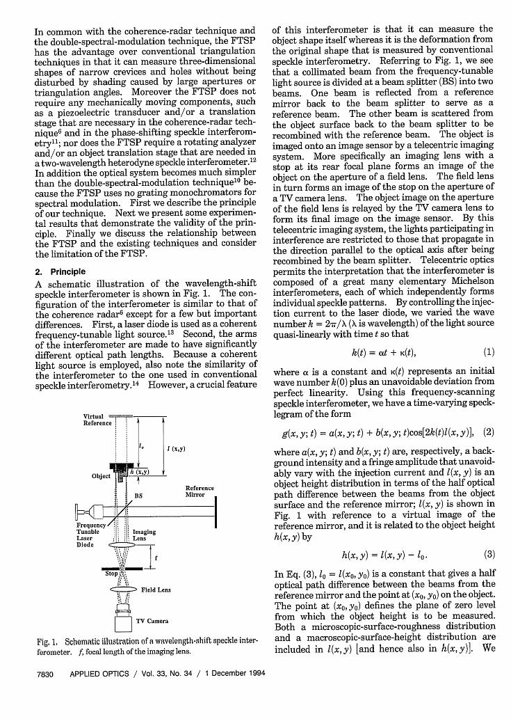
Note that the temporal carrier frequency depends onthe height of the object h(x, y) at the correspondingposition as shown schematically in Fig. 2. The Fou-rier-transform technique7 8 (FTT) is particularly suitedto the analysis of such a fringe signal as expressed byEq. (6). Originally the FTT was proposed for theanalysis of a fringe pattern with a spatial carrierfrequency, 7-9 but it can also be applied to a fringesignal with a temporal carrier frequency. 15 We havedemonstrated the distance measurement of a targetmirror by using the FTT,' 6 which may be interpretedas a special case of the height measurement for anobject with no spatial structure, i.e., I(x, y) = (xo, yo) =1o with l being the distance. Now we extend it to amore general case including a diffusive object with acomplex and discontinuous height distribution. Wecompute the Fourier transform of Eq. (6) with respectto the time variable t:
G(x, y; f) = A(x, y; f ) + C[x, y; f - fo(x, y)]
+ C*{x, y; -[f + fo(x, Y)}, (7)
where * denotes a complex conjugate, the uppercaseletters denote the Fourier spectra of the signalsexpressed by the corresponding lower-case letters,
Time t
Space
Space x
Object
Fig. 2. Time variation of a specklegram with temporal frequen-cies dependent on the height of the object h(x, y). The objectshown at the bottom is imaged onto the (x-y) plane so that eachpoint in the x-y plane corresponds to a point on the object wherethe height is h(x, y).
c(x,y; t) = /2 b(x,y; t)exp i[4(x,y; t)]. (8)
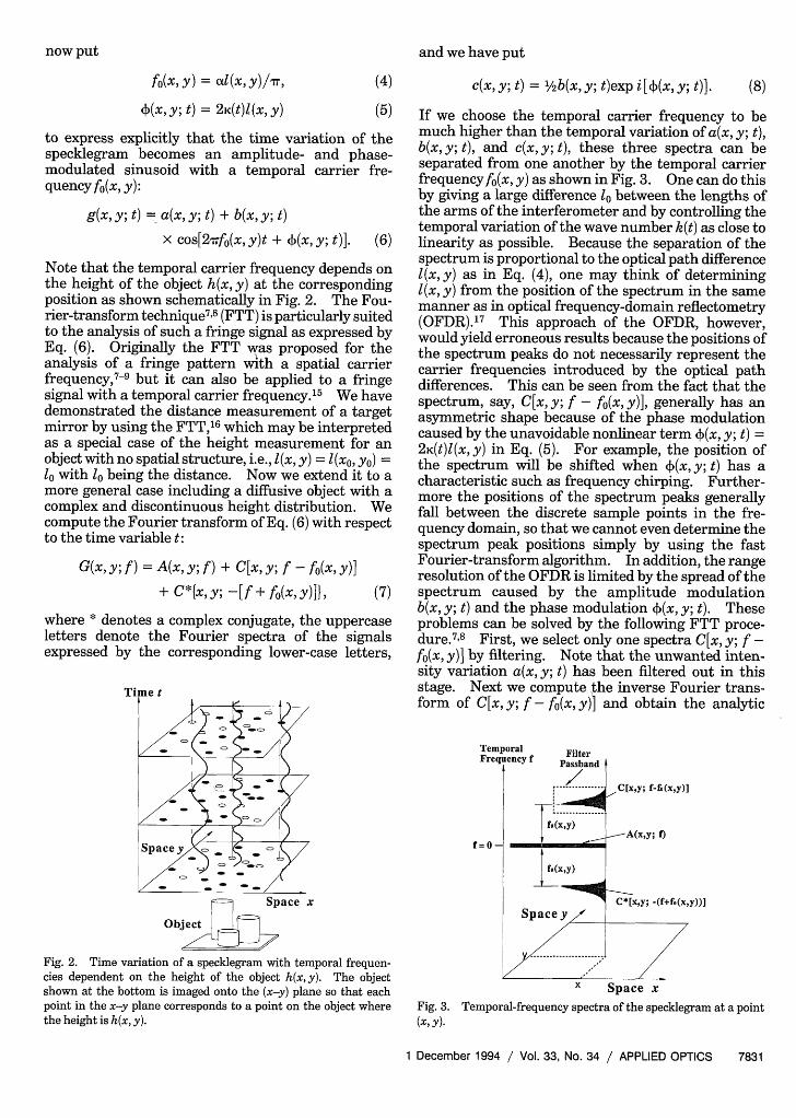
If we choose the temporal carrier frequency to bemuch higher than the temporal variation of a(x, y; t),b(x, y; t), and c(x, y; t), these three spectra can beseparated from one another by the temporal carrierfrequency fo(x, y) as shown in Fig. 3. One can do thisby giving a large difference between the lengths ofthe arms of the interferometer and by controlling thetemporal variation of the wave number k(t) as close tolinearity as possible. Because the separation of thespectrum is proportional to the optical path differencel(x, y) as in Eq. (4), one may think of determiningl(x, y) from the position of the spectrum in the samemanner as in optical frequency-domain reflectometry(OFDR).17 This approach of the OFDR, however,would yield erroneous results because the positions ofthe spectrum peaks do not necessarily represent thecarrier frequencies introduced by the optical pathdifferences. This can be seen from the fact that thespectrum, say, C[x, y; f - fo(x, y)], generally has anasymmetric shape because of the phase modulationcaused by the unavoidable nonlinear term +(x, y; t) =2 K(t)l(x, y) in Eq. (5). For example, the position ofthe spectrum will be shifted when (x, y; t) has acharacteristic such as frequency chirping. Further-more the positions of the spectrum peaks generallyfall between the discrete sample points in the fre-quency domain, so that we cannot even determine thespectrum peak positions simply by using the fastFourier-transform algorithm. In addition, the rangeresolution of the OFDR is limited by the spread of thespectrum caused by the amplitude modulationb(x, y; t) and the phase modulation +(x, y; t). Theseproblems can be solved by the following FTT proce-dure.7 8 First, we select only one spectra C[x, y; f -fo(x, y)] by filtering. Note that the unwanted inten-sity variation a(x, y; t) has been filtered out in thisstage. Next we compute the inverse Fourier trans-form of C[x, y; f - fo(x, y)] and obtain the analytic
TempiFrequ
f=O-
ral Filterency f Passband
... ............
_ .(x,y)J3(Y)
Spaxy)
Space yy
11CIx'y; f-f.(xy)]
-A(x,y; f)
C*[xy; (f+fo(xy))]
yz'W'/ ''';;;;.1
X Space x
Fig. 3. Temporal-frequency spectra of the specklegram at a point(x, y).
1 December 1994 / Vol. 33, No. 34 / APPLIED OPTICS 7831
now put
signal
c(x, y; t)exp[2Trif0 (x, y)t]
= 1/ 2b(x, y; t)exp{i[2rfo(x, y)t + +(x, y; t)]}. (9)
Then we calculate a complex logarithm of this ana-lytic signal:
logtc(x, y; t)exp[2,rif0(x, y)t])
= log[1/2 b(x,y; t)] + i[2rrfo(x,y)t + 4(x,y; t)]. (10)
Now we have the phase of the fringe signal in theimaginary part completely separated from the un-wanted amplitude variation b(x, y; t) in the real part.Because the phase is wrapped into the range (-Tr, Tr]by modulo 2ir and k(t) cannot be extended down tozero, the initial phase CP0(x, y) remains indeterminate.We first unwrap the phase by using a one-dimen-sional phase-unwrapping algorithm7"18 and then ex-press this indeterminate initial phase explicitly byputting
cF(x, y; t) + cFo(x, y) = 2k(t)l(x, y) (11)
= 2rfo(x, y)t + 4(x,y; t). (12)
The indeterminate initial phase can be eliminated bydifferentiation with t because it is a constant withtime:
atD(x, y; t) dk(t) (13)at = 21(x,y) dt
Note that Eq. (13) gives an instantaneous angularfrequency of the fringe signal. Because we generallyhave no exact knowledge of k(t), we attach a referenceobject with a known height difference between twopoints, say, hR = l(XR, YR) - I(xo, YO). Then we caneliminate k(t) to obtain the final formula for theheight distribution,
h(x,y) = hR X
dt [(D(x, y; t) - D(x0, yo; t)]a~~4t ~ '(x R~ y R~t) - t1(x oyo~t ]I (1 4 )
dt [(D(XR, YR; t) (xo, yo; t)]
where (#) denotes a time-averaging operation overthe period during which one records the interfero-gram by shifting the wavelength of the light source.Note that the time derivatives of the phases in thenumerator and the denominator give instantaneousangular frequencies that are proportional to theheights of the unknown object and the known refer-ence, respectively. One may thus interpret the tech-nique as performing OFDR at every instant of time,for both the object and the reference, based on theinstantaneous angular frequencies. The most impor-tant difference from the conventional OFDR is theeffective use of the data, which enables improvementin the accuracy of the measurement. Although the
conventional OFDR estimates the distance from asingle-frequency component at the spectrum peakonly, this technique makes full use of the instanta-neous angular frequencies obtained at any instant oftime for the estimation of the object height, regard-less of whether their values deviate from the spec-trum peak. Note also that the time-averaging opera-tion should be performed on the ratio of theinstantaneous angular frequencies (which does notvary with time except for its fluctuations caused bynoise), not on the instantaneous angular frequenciesthemselves [which vary with dK(t)/dt when the shiftof the wave number deviates from perfect linearity].
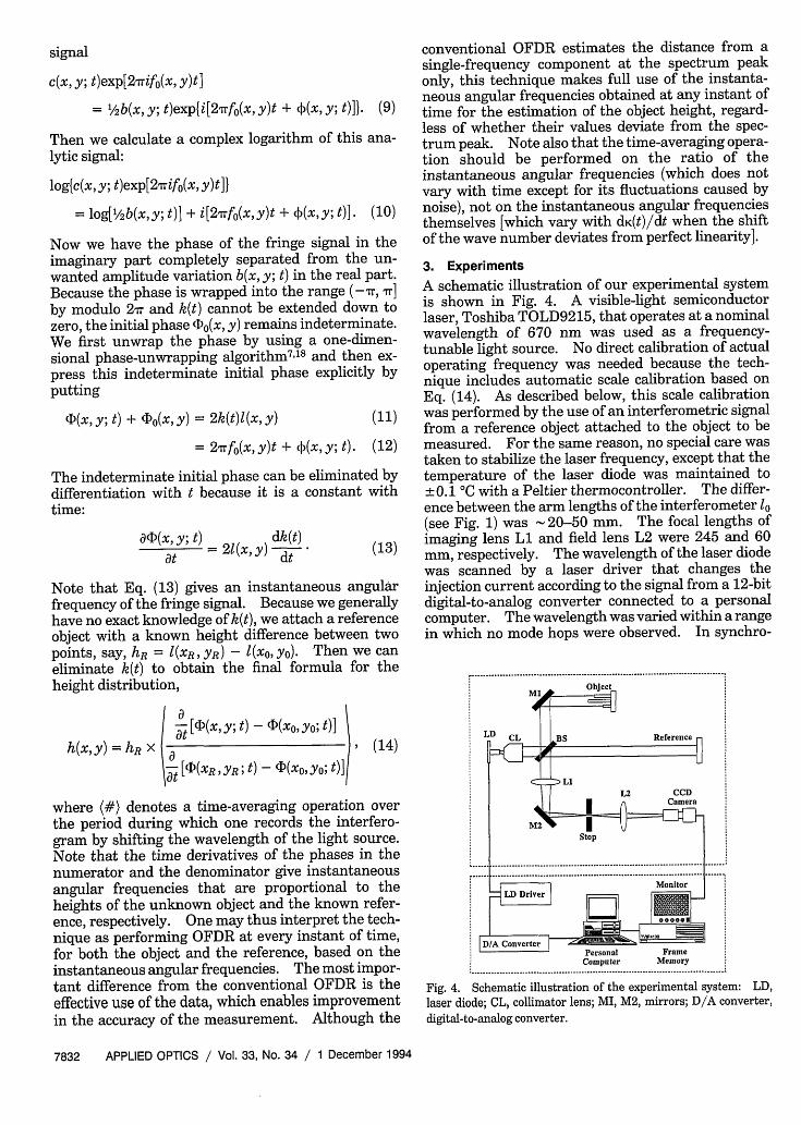
3. ExperimentsA schematic illustration of our experimental systemis shown in Fig. 4. A visible-light semiconductorlaser, Toshiba TOLD9215, that operates at a nominalwavelength of 670 nm was used as a frequency-tunable light source. No direct calibration of actualoperating frequency was needed because the tech-nique includes automatic scale calibration based onEq. (14). As described below, this scale calibrationwas performed by the use of an interferometric signalfrom a reference object attached to the object to bemeasured. For the same reason, no special care wastaken to stabilize the laser frequency, except that thetemperature of the laser diode was maintained to±0.1 C with a Peltier thermocontroller. The differ-ence between the arm lengths of the interferometer 1(see Fig. 1) was 20-50 mm. The focal lengths ofimaging lens Li and field lens L2 were 245 and 60mm, respectively. The wavelength of the laser diodewas scanned by a laser driver that changes theinjection current according to the signal from a 12-bitdigital-to-analog converter connected to a personalcomputer. The wavelength was varied within a rangein which no mode hops were observed. In synchro-
I D/A Converter I .=Personal FrameComputer Memory
:.......................................................................................... .................................................
Fig. 4. Schematic illustration of the experimental system: LD,laser diode; CL, collimator lens; MI, M2, mirrors; D/A converter,digital-to-analog converter.
7832 APPLIED OPTICS / Vol. 33, No. 34 / 1 December 1994
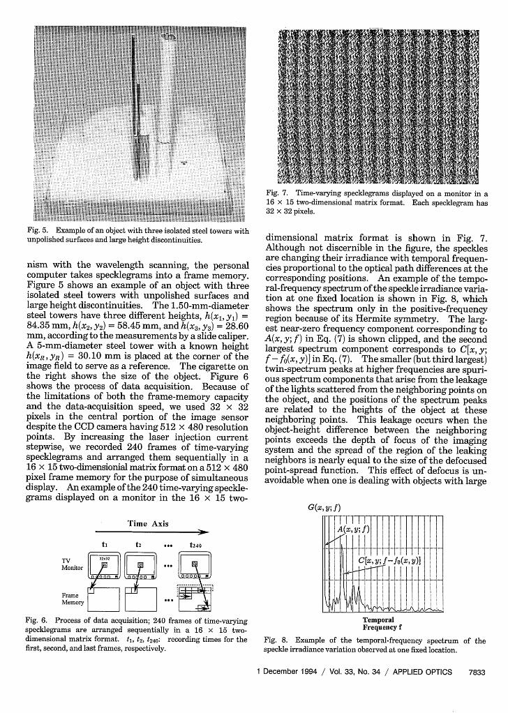
Fig. 5. Example of an object with three isolated steel towers withunpolished surfaces and large height discontinuities.
nism with the wavelength scanning, the personalcomputer takes specklegrams into a frame memory.Figure 5 shows an example of an object with threeisolated steel towers with unpolished surfaces andlarge height discontinuities. The 1.50-mm-diametersteel towers have three different heights, h(xl, Yl) =84.35 mm, h(x2, Y2) = 58.45 mm, and h(x3, y3 ) = 28.60mm, according to the measurements by a slide caliper.A 5-mm-diameter steel tower with a known heighth(xR, yR) = 30.10 mm is placed at the corner of theimage field to serve as a reference. The cigarette onthe right shows the size of the object. Figure 6shows the process of data acquisition. Because ofthe limitations of both the frame-memory capacityand the data-acquisition speed, we used 32 x 32pixels in the central portion of the image sensordespite the CCD camera having 512 x 480 resolutionpoints. By increasing the laser injection currentstepwise, we recorded 240 frames of time-varyingspecklegrams and arranged them sequentially in a16 x 15 two-dimensionial matrix format on a 512 x 480pixel frame memory for the purpose of simultaneousdisplay. An example of the 240 time-varying speckle-grams displayed on a monitor in the 16 x 15 two-
Time Axis
ti t2 *. t240
TV 3
Monitor S'.
Frame FMemory
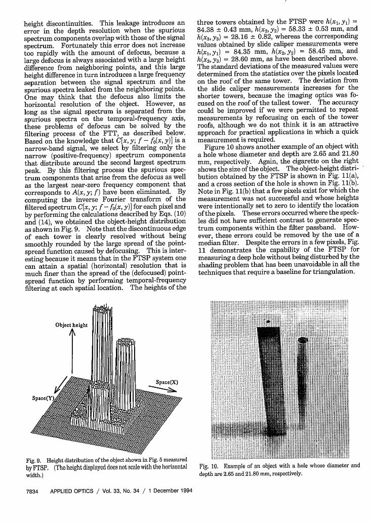
Fig. 6. Process of data acquisition; 240 frames of time-varyingspecklegrams are arranged sequentially in a 16 x 15 two-dimensional matrix format. t, t2, t240: recording times for thefirst, second, and last frames, respectively.
Fig. 7. Time-varying specklegrams displayed on a monitor in a16 x 15 two-dimensional matrix format. Each specklegram has32 x 32 pixels.
dimensional matrix format is shown in Fig. 7.Although not discernible in the figure, the specklesare changing their irradiance with temporal frequen-cies proportional to the optical path differences at thecorresponding positions. An example of the tempo-ral-frequency spectrum of the speckle irradiance varia-tion at one fixed location is shown in Fig. 8, whichshows the spectrum only in the positive-frequencyregion because of its Hermite symmetry. The larg-est near-zero frequency component corresponding toA(x, y; f) in Eq. (7) is shown clipped, and the secondlargest spectrum component corresponds to C[x, y;f - fo(x, y)] in Eq. (7). The smaller (but third largest)twin-spectrum peaks at higher frequencies are spuri-ous spectrum components that arise from the leakageof the lights scattered from the neighboring points onthe object, and the positions of the spectrum peaksare related to the heights of the object at theseneighboring points. This leakage occurs when theobject-height difference between the neighboringpoints exceeds the depth of focus of the imagingsystem and the spread of the region of the leakingneighbors is nearly equal to the size of the defocusedpoint-spread function. This effect of defocus is un-avoidable when one is dealing with objects with large
G(x, y; f )
C[x'y;f-fo(X'y)]
TemporalFrequency f
Fig. 8. Example of the temporal-frequency spectrum of thespeckle irradiance variation observed at one fixed location.
1 December 1994 / Vol. 33, No. 34 / APPLIED OPTICS 7833
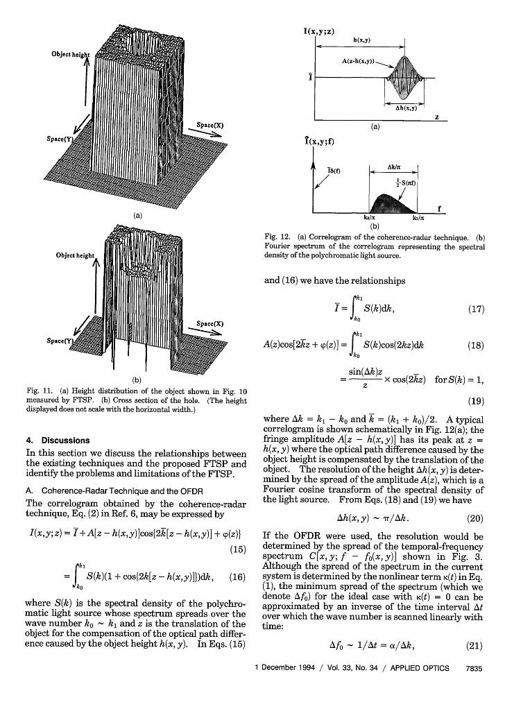
height discontinuities. This leakage introduces anerror in the depth resolution when the spuriousspectrum components overlap with those of the signalspectrum. Fortunately this error does not increasetoo rapidly with the amount of defocus, because alarge defocus is always associated with a large heightdifference from neighboring points, and this largeheight difference in turn introduces a large frequencyseparation between the signal spectrum and thespurious spectra leaked from the neighboring points.One may think that the defocus also limits thehorizontal resolution of the object. However, aslong as the signal spectrum is separated from thespurious spectra on the temporal-frequency axis,these problems of defocus can be solved by thefiltering process of the FTT, as described below.Based on the knowledge that C[x, y; f - fo(x, y)] is anarrow-band signal, we select by filtering only thenarrow (positive-frequency) spectrum componentsthat distribute around the second largest spectrumpeak. By this filtering process the spurious spec-trum components that arise from the defocus as wellas the largest near-zero frequency component thatcorresponds to A(x, y; f ) have been eliminated. Bycomputing the inverse Fourier transform of thefiltered spectrum C[x, y; f - fo(x, y)] for each pixel andby performing the calculations described by Eqs. (10)and (14), we obtained the object-height distributionas shown in Fig. 9. Note that the discontinuous edgeof each tower is clearly resolved without beingsmoothly rounded by the large spread of the point-spread function caused by defocusing. This is inter-esting because it means that in the FTSP system onecan attain a spatial (horizontal) resolution that ismuch finer than the spread of the (defocused) point-spread function by performing temporal-frequencyfiltering at each spatial location. The heights of the
Object height
i f
three towers obtained by the FTSP were h(xl, yl) =84.38 ± 0.43 mm, h(x2,y2) = 58.33 ± 0.53 mm, andh(x3, y3) = 28.16 + 0.82, whereas the correspondingvalues obtained by slide caliper measurements wereh(xl, Yl) = 84.35 mm, h(x2 , Y2) = 58.45 mm, andh(x3, y3) = 28.60 mm, as have been described above.The standard deviations of the measured values weredetermined from the statistics over the pixels locatedon the roof of the same tower. The deviation fromthe slide caliper measurements increases for theshorter towers, because the imaging optics was fo-cused on the roof of the tallest tower. The accuracycould be improved if we were permitted to repeatmeasurements by refocusing on each of the towerroofs, although we do not think it is an attractiveapproach for practical applications in which a quickmeasurement is required.
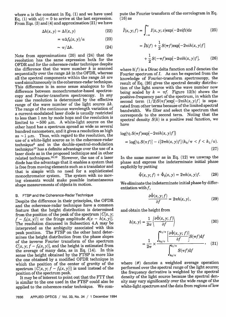
Figure 10 shows another example of an object witha hole whose diameter and depth are 2.65 and 21.80mm, respectively. Again, the cigarette on the rightshows the size of the object. The object-height distri-bution obtained by the FTSP is shown in Fig. 11(a),and a cross section of the hole is shown in Fig. 11(b).Note in Fig. 11(b) that a few pixels exist for which themeasurement was not successful and whose heightswere intentionally set to zero to identify the locationof the pixels. These errors occurred where the speck-les did not have sufficient contrast to generate spec-trum components within the filter passband. How-ever, these errors could be removed by the use of amedian filter. Despite the errors in a few pixels, Fig.11 demonstrates the capability of the FTSP formeasuring a deep hole without being disturbed by theshading problem that has been unavoidable in all thetechniques that require a baseline for triangulation.
Space(X)
Fig. 9. Height distribution of the object shown in Fig. 5 measured
by FTSP. (The height displayed does not scale with the horizontalwidth.)
Fig, 10, Example of an object with a hole whose diameter and
depth are 2.65 and 21.80 mm, respectively.
7834 APPLIED OPTICS / Vol. 33, No. 34 / 1 December 1994
I(x,Y;Z)
i
(a)
h(x,y)
Ah(xy)
Z
(a)
ko/f
(b)Fig. 12. (a) Correlogram of the coherence-radar technique. (b)Fourier spectrum of the correlogram representing the spectraldensity of the polychromatic light source.
and (16) we have the relationships
Spac(Y f
(b)Fig. 11. (a) Height distribution of the object shown in Fig. 10measured by FTSP. (b) Cross section of the hole. (The heightdisplayed does not scale with the horizontal width.)
4. Discussions
In this section we discuss the relationships betweenthe existing techniques and the proposed FTSP andidentify the problems and limitations of the FTSP.
A. Coherence-Radar Technique and the OFDRThe correlogram obtained by the coherence-radartechnique, Eq. (2) in Ref. 6, may be expressed by
I(x,y;z) = I+A[z - h(x,y)]cos{2k[z - h(x,y)] + p(z)}
(15)
- J S(k)(1 + cos{2k[z - h(x,y)]})dk, (16)
where S(k) is the spectral density of the polychro-matic light source whose spectrum spreads over thewave number ko - k and z is the translation of theobject for the compensation of the optical path differ-ence caused by the object height h(x, y). In Eqs. (15)
rki
I = S(k)dk,
ko
A(z)cos[2kz + yp(z)] = f S(k)cos(2kz)dk
sin(Ak)z= x cos(2kz)
(17)
(18)
for S(k) = 1,
(19)
where Ak = k - ko and k = (kl + k)/2. A typicalcorrelogram is shown schematically in Fig. 12(a); thefringe amplitude A[z - h(x, y)] has its peak at z =h(x, y) where the optical path difference caused by theobject height is compensated by the translation of theobject. The resolution of the height Ah(x, y) is deter-mined by the spread of the amplitude A(z), which is aFourier cosine transform of the spectral density ofthe light source. From Eqs. (18) and (19) we have
Ah(x, y) Tr/Ak. (20)
If the OFDR were used, the resolution would bedetermined by the spread of the temporal-frequencyspectrum C[x,y; f - fo(x,y)] shown in Fig. 3.Although the spread of the spectrum in the currentsystem is determined by the nonlinear term K(t) in Eq.(1), the minimum spread of the spectrum (which wedenote Afo) for the ideal case with K(t) = 0 can beapproximated by an inverse of the time interval Atover which the wave number is scanned linearly withtime:
Afi - 1/At = a/Ak, (21)
1 December 1994 / Vol. 33, No. 34 / APPLIED OPTICS 7835
A(z-h(x,y))_
where a is the constant in Eq. (1) and we have Eq. (1) with K(t) = 0 to arrive at the last expresEFrom Eqs. (3) and (4) and approximation (21) we I
Ah(x,y) = AI(x,y)
= TrAfo(x, y)/ax
v 7r/Ak.
Note from approximations (20) and (24) that theresolution has the same expression both for theOFDR and for the coherence-radar technique despitethe difference that the wave number k is scannedsequentially over the range Ak in the OFDR, whereasall the spectral components within the range Ak areused simultaneously in the coherence-radar technique.This difference is in some sense analogous to thedifference between monochromator-based spectros-copy and Fourier-transform spectroscopy. In anycase the resolution is determined by the effectiverange of the wave number of the light source Ak.The range of the continuous wavelength variation ofa current-modulated laser diode is usually restrictedto less than 1 nm by mode hops and the resolution islimited to 500 [im. A white-light source on theother hand has a spectrum spread as wide as severalhundred nanometers, and it gives a resolution as highas 1 jm. Thus, with regard to the resolution, theuse of a white-light source as in the coherence-radartechniques and in the double-spectral-modulationtechniques has a definite advantage over the use of alaser diode as in the proposed technique and in otherrelated techniques. 61 9 However, the use of a laserdiode has the advantage that it enables a system thatis free from moving elements such as a translator andthat is simple with no need for a sophisticatedmonochromator system. The system with no mov-ing elements would make possible instantaneousshape measurements of objects in motion.
B. FTSP and the Coherence-Radar Technique
Despite the difference in their principles, the OFDRand the coherence-radar technique have a commonfeature that the height distribution is determinedfrom the position of the peak of the spectrum I C[x, y;f - fo(x, y)] I or the fringe amplitude A[z - h(x, y)].The resolution discussed in Subsection 4.A may beinterpreted as the ambiguity associated with thispeak position. The FTSP on the other hand deter-mines the height distribution from the phase slopesof the inverse Fourier transform of the spectrumC[x, y; f - fo(x, y)], and the height is estimated fromthe average of many data, as in Eq. (14). In thissense the height obtained by the FTSP is more likethe one obtained by a modified OFDR technique inwhich the position of the center of gravity of thespectrum I C[x, y; f - fo(x, y)] is used instead of theposition of the spectrum peak.
It may be of interest to point out that the FTT thatis similar to the one used in the FTSP could also beapplied to the coherence-radar technique. We com-
pute the Fourier transform of the correlogram in Eq.(16) as
(22) I(x, y; f) = I(x, y; z)exp(-2rifz)dz
= 18(f) + 2 S(rf )exp[-2Trih(x, y) f ]
+ S(-rrf)exp[-2 rrih(x, y)f ],
(25)
(26)
where 8( f ) is a Dirac delta function and I denotes theFourier spectrum of I. As can be expected from theknowledge of Fourier-transform spectroscopy, theresult of Eq. (26) gives the spectral density distribu-tion of the light source with the wave number nowbeing scaled by k = rf. Figure 12(b) shows thepositive-frequency part of the spectrum, in which thesecond term (1/2)S(rrf)exp[-27rih(x, y)f] is sepa-rated from other terms because of the limited spectralbandwidth. We filter and select the spectrum thatcorresponds to the second term. Noting that thespectral density S(k) is a positive real function, wehave
log{'/2 S(rrf)exp[-2,rih(x, y)f ]}
= log['/2 S(,rf)] - i[2-rrh(x,y)f](ko/rr < f < kl/rr).
(27)
In the same manner as in Eq. (12) we unwrap thephase and express the indeterminate initial phaseexplicitly by putting
¢(x, y; f) + CO(x, y) = 2,rrh(x, y)f. (28)
We eliminate the indeterminate initial phase by differ-entiation with f,
( _____)= 2Trh(x, y),af
and obtain the height from
h(x, y) 1 a(a¢(x, Y; f ))hY, ) 2 r2 a f |
- 17 acF(x, y; X 1S(7Trf)df1 Jko/,r L a
J S(rf)df0o/r
(29)
(30)
(31)
where (#) denotes a weighted average operationperformed over the spectral range of the light source;the frequency derivative is weighted by the spectraldensity of the light source because the spectral den-sity may vary significantly over the wide range of thewhite-light spectrum and the data from regions of low
7836 APPLIED OPTICS / Vol. 33, No. 34 / 1 December 1994
spectral density become less reliable than those fromregions of high spectral density. Note that Eq. (30)corresponds to Eq. (14) of the FTSP. In Eq. (30) noreference object is used for calibration, because wehave implicitly assumed an ideal z translator thatperforms a perfectly linear translation of the objectwithout any deviation from linearity such as the onedenoted by an unknown function K(t) in Eq. (1).Thus we have shown that the FTT could also beapplied to the coherence-radar technique.
5. ConclusionWe have proposed a new technique for automatedprofilometry that is based on the Fourier-transformfringe analysis of spatiotemporal specklegrams pro-duced by a wavelength-shift interferometer with alaser diode as a frequency-tunable light source.Unlike conventional moir6 and FTP techniques, theproposed technique permits the objects to have discon-tinuous height steps and/or surfaces spatially iso-lated from one another. We have presented experi-mental results that demonstrate the validity of theprinciple. We have discussed the performance of theproposed technique and identified its problems andlimitations. We have also clarified the relationshipsbetween the proposed technique and other existingtechniques and pointed out that a similar techniquecould be applied to the coherence-radar technique.
Part of this research was supported by a Grant-in-Aid for Scientific Research from the Ministry ofEducation, Science and Culture, Japan.
References1. See, for example, H.-J. Tiziani, "Optical techniques for shape
measurements," in Proceedings of the Second InternationalWorkshop on Automatic Processing of Fringe Patterns, Fringe'93, W. Jptner and W. Osten, eds. (Akademie Verlag, Berlin,1993), pp. 165-174.
2. See, for example, D. M. Meadows, W. 0. Johnson, and J. B.Allen, "Generation of surface contours by moir6 patterns,"Appl. Opt. 9, 942-947 (1970); H. Takasaki, "Moir6 topogra-phy," Appl. Opt. 9, 1467-1472 (1970).
3. M. Takeda and K. Mutoh, "Fourier transform profilometry forthe automatic measurement of 3-D object shapes," Appl. Opt.22, 3977-3982 (1983).
4. See, for example, G. Hausler and W. Heckel, "Light sectioning
with large depth and high resolution," Appl. Opt. 27, 5165-5169 (1988).
5. See, for example, G. Seitz and H.-J. Tiziani, "Resolution limitsof active triangulation systems by defocusing," Opt. Eng. 32,1374-1383 (1993).
6. T. Dresel, G. Hdusler, and H. Venzke, "Three-dimensionalsensing of rough surfaces by coherence radar," Appl. Opt. 31,919-925 (1992).
7. M. Takeda, H. Ina, and S. Kobayashi, "Fourier-transformmethod of fringe pattern analysis for computer-based topogra-phy and interferometry," J. Opt. Soc. Am. 72, 156-160 (1982).
8. C. Roddier and F. Roddier, "Interferogram analysis usingFourier transform techniques," Appl. Opt. 26, 1668-1673(1987).
9. See, for example, M. Takeda, "Spatial-carrier fringe-patternanalysis and its applications to precision interferometry andprofilometry: an overview," Ind. Metrol. 1, 79-99 (1990).
10. J. E. Calatroni, P. Sandoz, and G. Tribillon, "Surface profilingby means of double spectral modulation," Appl. Opt. 32,30-37(1993).
11. A. A. M. Maas, "Shape measurement using phase shiftingspeckle interferometry," in Laser Interferometry IV Com-puter-Aided Interferometry, R. J. Pryputniewicz, ed., Proc.Soc. Photo-Opt. Instrum. Eng. 1553, 558-568 (1991).
12. A. F. Fercher, H. Z. Hu, and U. Vry, "Rough surface interfer-ometry with two-wavelength heterodyne speckle interferom-eters," Appl. Opt. 24, 2181-2188 (1985).
13. See, for example, Y. Ishii, "Recent developments in laser-diodeinterferometry," Opt. Lasers Eng. 14, 293-309 (1991).
14. See, for example, K. Creath, "Phase-shifting speckle interfer-ometry," Appl. Opt. 24, 3053-3058 (1985); S. Nakadate and H.Saito, "Fringe scanning speckle-pattern interferometry, " Appl.Opt. 24, 2172-2180 (1985).
15. M. Takeda and M. Kitoh, "Spatiotemporal frequency-multi-plex heterodyne interferometry," J. Opt. Soc. Am. A 7, 1607-1614 (1992).
16. M. Suematsu and M. Takeda, "Wavelength-shift interferom-etry for distance measurements using the Fourier-transformtechnique for fringe analysis," Appl. Opt. 30, 4046-4055(1991).
17. S. A. Kingsley and D. E. N. Davies, "OFDR diagnostics forfiber and integrated-optic systems," Electron. Lett. 21, 434-435 (1985).
18. See, for example, K. Itoh, "Analysis of the phase unwrappingalgorithm," Appl. Opt. 21, 2470 (1982).
19. K. Hotate and T. Okugawa, "Selective extraction of a two-dimensional optical image by synthesis of the coherencefunction," Opt. Lett. 17,1529-1531 (1992).
1 December 1994 / Vol. 33, No. 34 / APPLIED OPTICS 7837