Embed Size (px)
Citation preview
Four Span Simply Supported Steel Plate
Girder Input As‐Built Model Only
September, 2011
VDOT VERSION 6.2 1
FOUR SPAN SIMPLY SUPPORTED STEEL PLATE GIRDER INPUT
AS‐BUILT MODEL ONLY
Table of Contents 1. Creating a New Bridge File .............................................................................................................. 5
2. Material Properties Input ............................................................................................................... 8
Structural Steel ................................................................................................................................ 8
Concrete......................................................................................................................................... 10
Reinforcing Steel ........................................................................................................................... 12
3. Appurtenances Input .................................................................................................................... 14
Parapet .......................................................................................................................................... 14
Impact / Dynamic Load Allowance Input ..................................................................................... 15
4. Factors Input .................................................................................................................................. 16
LRFR ............................................................................................................................................... 16
5. Superstructure Definitions Input .................................................................................................. 17
Load Case Description ................................................................................................................... 19
Framing Plan Detail ....................................................................................................................... 20
Structure Typical Section .............................................................................................................. 23
Stiffener Definitions ...................................................................................................................... 28
6. Member Inputs .............................................................................................................................. 32
Member Loads ............................................................................................................................... 32
Supports ......................................................................................................................................... 34
Member Alternatives .................................................................................................................... 36
Girder Profile .................................................................................................................... 42
Deck Profile ...................................................................................................................... 45
Haunch Profile .................................................................................................................. 48
Lateral Support ................................................................................................................. 50
Stiffener Ranges ............................................................................................................... 52
Bearing Stiffener Locations .............................................................................................. 56
Copying a Member ........................................................................................................................ 58
Linking a Member .......................................................................................................................... 67
Live Load Distribution ................................................................................................................... 70
VDOT VERSION 6.2 2
FOUR SPAN SIMPLY SUPPORTED STEEL PLATE GIRDER INPUT
AS‐BUILT MODEL ONLY
7. Creating Additional Spans ............................................................................................................. 71
8. Bridge Alternatives ........................................................................................................................ 88
Bridge Alternatives ........................................................................................................................ 88
Superstructures ............................................................................................................................. 89
Superstructure Alternatives .......................................................................................................... 90
9. Rating the Structure ...................................................................................................................... 95
Appendices
A. AsBuilt Bridge Drawings 106 B. Diaphragm Load Calculations 111 C. Concrete Railing Load Calculations 112 D. Sample Load Rating Summary Form 113
VDOT VERSION 6.2 3
FOUR SPAN SIMPLY SUPPORTED STEEL PLATE GIRDER INPUT
AS‐BUILT MODEL ONLY
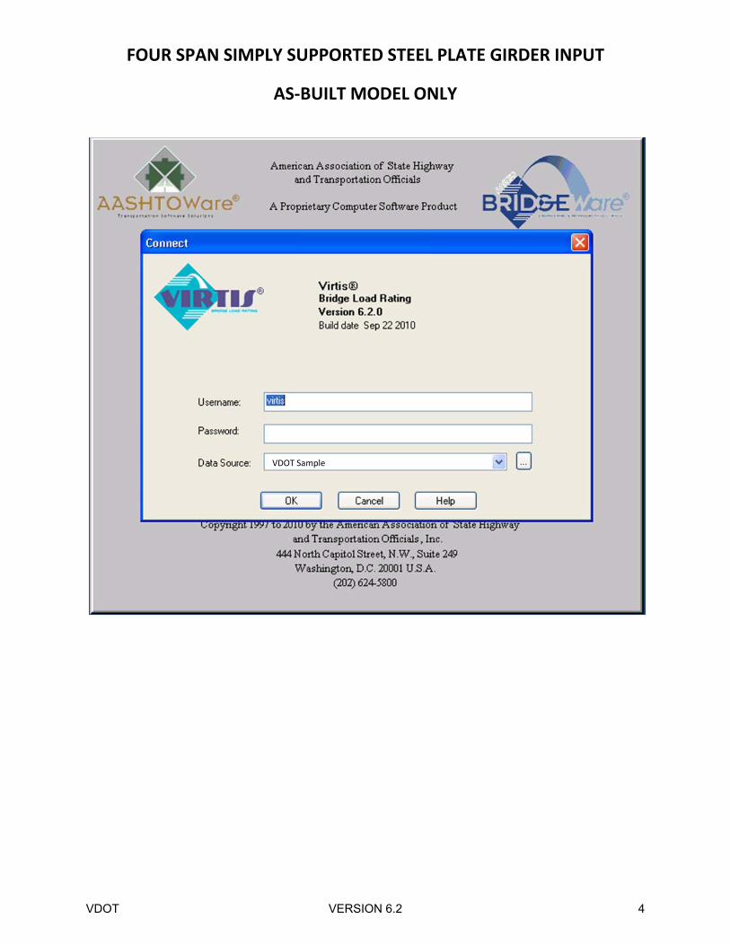
VDOT Sample
VDOT VERSION 6.2 4
FOUR SPAN SIMPLY SUPPORTED STEEL PLATE GIRDER INPUT
AS‐BUILT MODEL ONLY
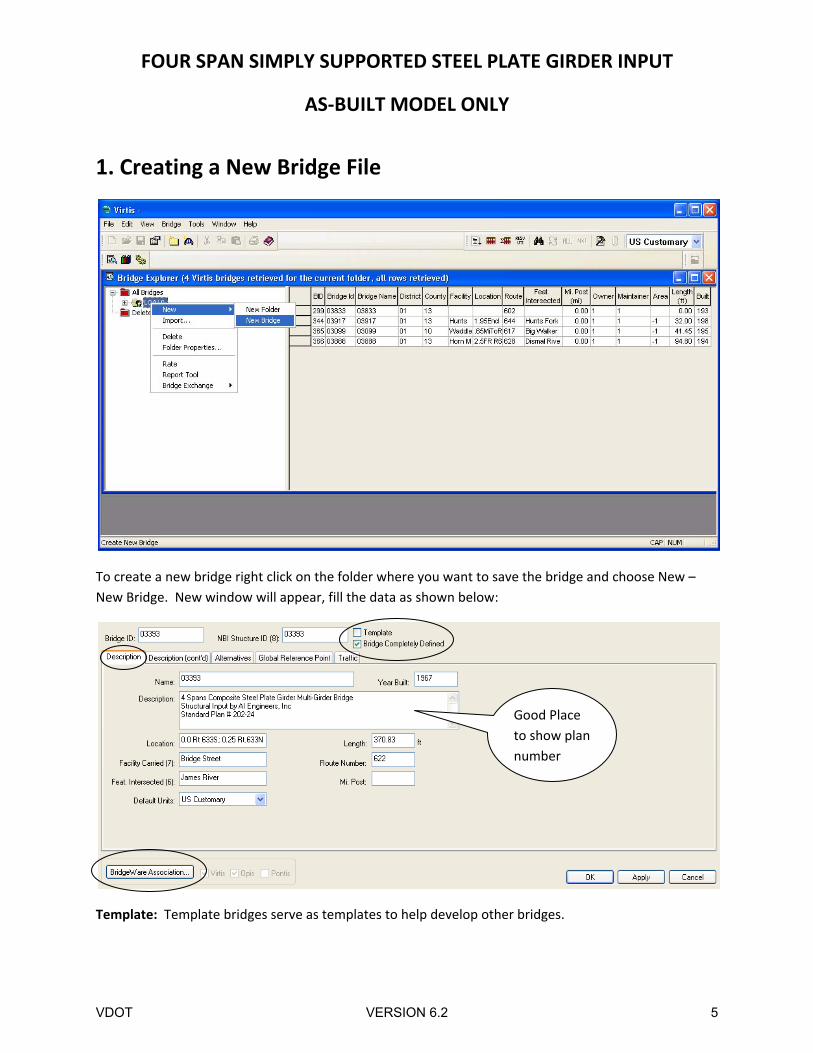
1. Creating a New Bridge File
To create a new bridge right click on the folder where you want to save the bridge and choose New –
New Bridge. New window will appear, fill the data as shown below:
Template: Template bridges serve as templates to help develop other bridges.
Good Place
to show plan
number
VDOT VERSION 6.2 5
FOUR SPAN SIMPLY SUPPORTED STEEL PLATE GIRDER INPUT
AS‐BUILT MODEL ONLY
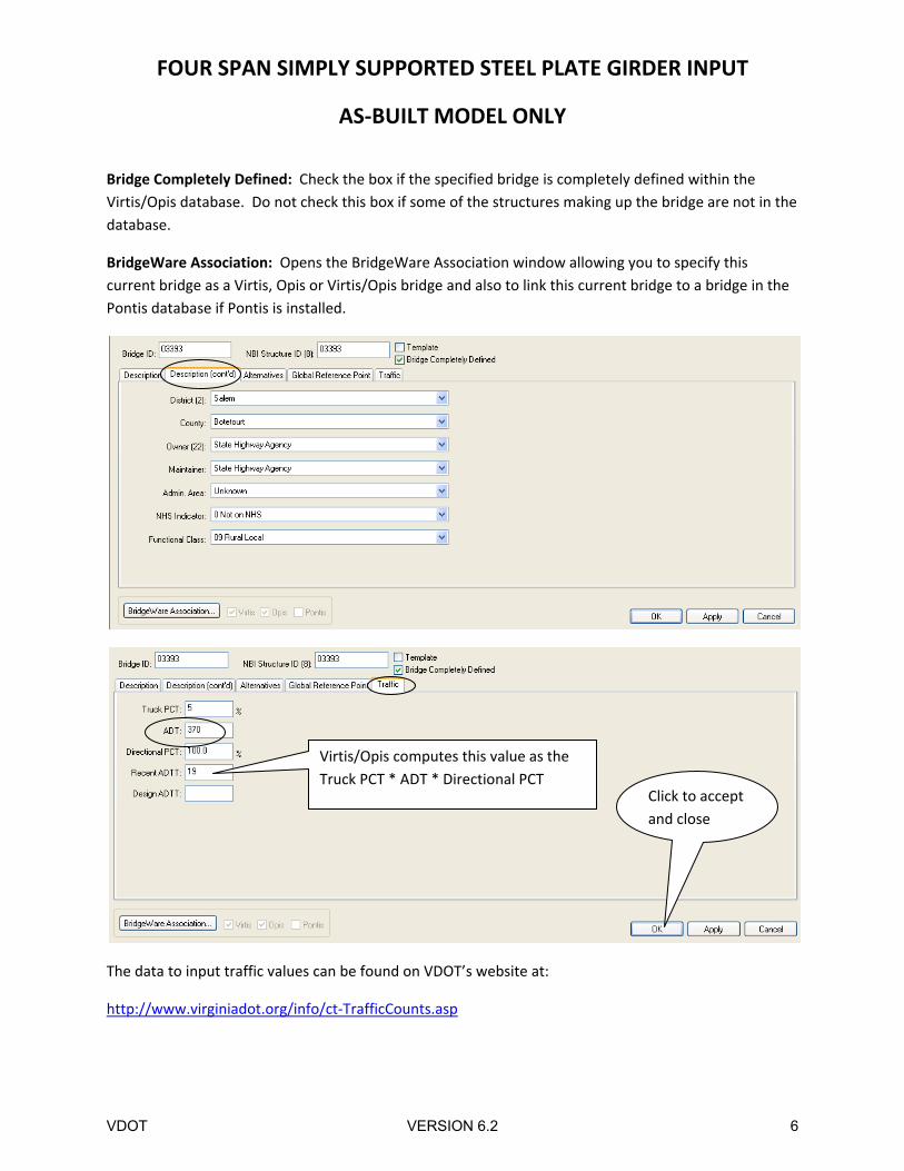
Bridge Completely Defined: Check the box if the specified bridge is completely defined within the
Virtis/Opis database. Do not check this box if some of the structures making up the bridge are not in the
database.
BridgeWare Association: Opens the BridgeWare Association window allowing you to specify this
current bridge as a Virtis, Opis or Virtis/Opis bridge and also to link this current bridge to a bridge in the
Pontis database if Pontis is installed.
The data to input traffic values can be found on VDOT’s website at:
http://www.virginiadot.org/info/ct‐TrafficCounts.asp
Virtis/Opis computes this value as the
Truck PCT * ADT * Directional PCT Click to accept
and close
VDOT VERSION 6.2 6
FOUR SPAN SIMPLY SUPPORTED STEEL PLATE GIRDER INPUT
AS‐BUILT MODEL ONLY
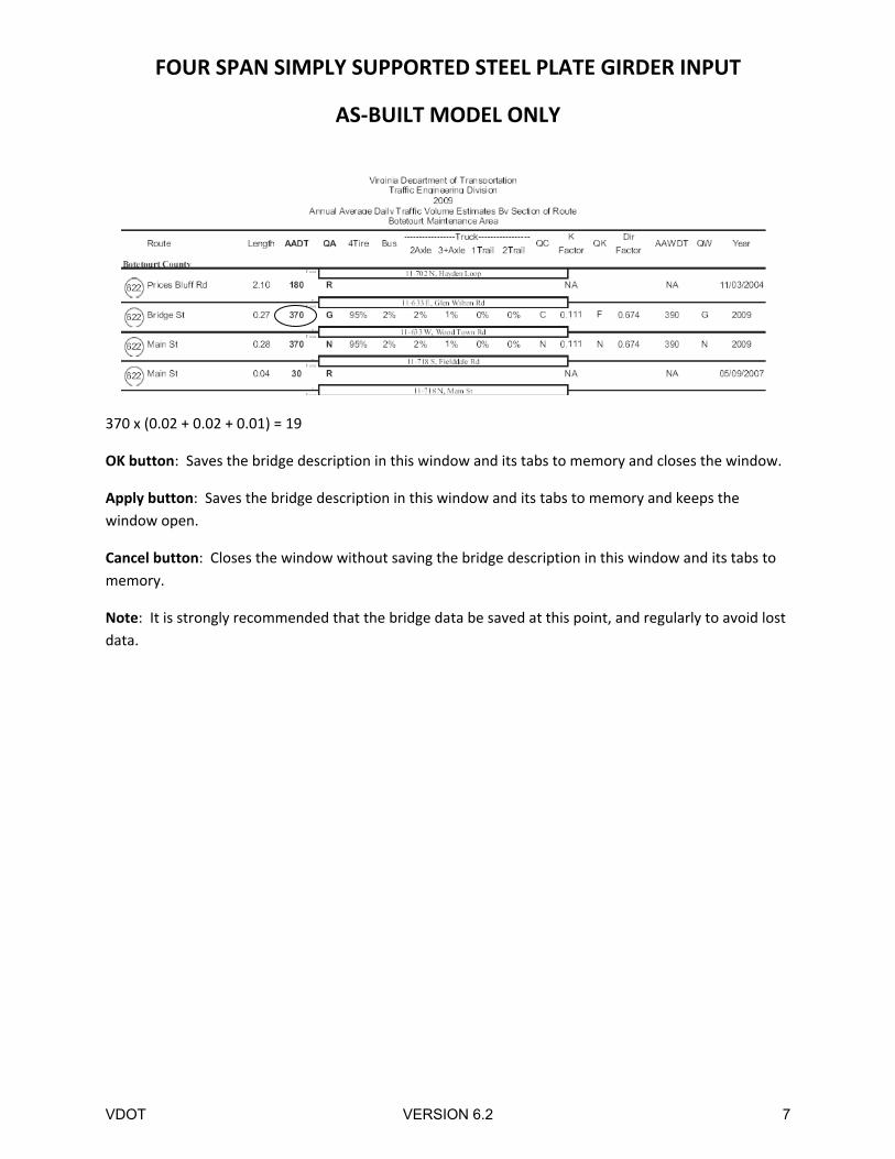
370 x (0.02 + 0.02 + 0.01) = 19
OK button: Saves the bridge description in this window and its tabs to memory and closes the window.
Apply button: Saves the bridge description in this window and its tabs to memory and keeps the
window open.
Cancel button: Closes the window without saving the bridge description in this window and its tabs to
memory.
Note: It is strongly recommended that the bridge data be saved at this point, and regularly to avoid lost
data.
VDOT VERSION 6.2 7
FOUR SPAN SIMPLY SUPPORTED STEEL PLATE GIRDER INPUT
AS‐BUILT MODEL ONLY
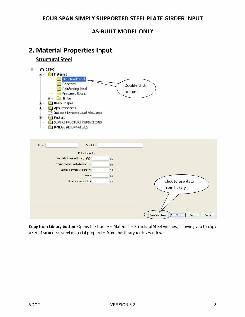
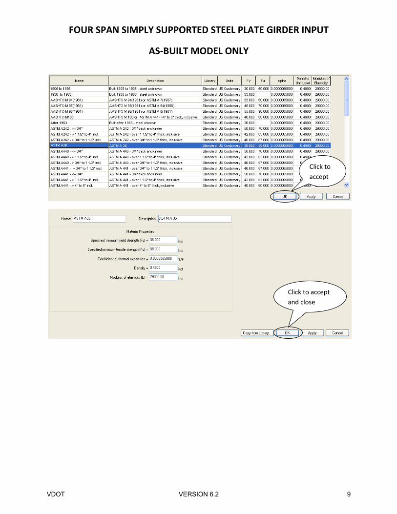
2. Material Properties Input Structural Steel
Copy from Library button: Opens the Library – Materials – Structural Steel window, allowing you to copy
a set of structural steel material properties from the library to this window.
Double click
to open
Click to use data
from library
VDOT VERSION 6.2 8
FOUR SPAN SIMPLY SUPPORTED STEEL PLATE GIRDER INPUT
AS‐BUILT MODEL ONLY
Click to
accept
Click to accept
and close
VDOT VERSION 6.2 9
FOUR SPAN SIMPLY SUPPORTED STEEL PLATE GIRDER INPUT
AS‐BUILT MODEL ONLY
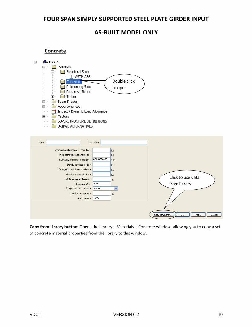
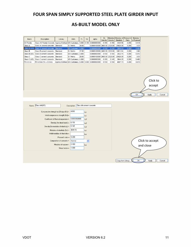
Concrete
Copy from Library button: Opens the Library – Materials – Concrete window, allowing you to copy a set
of concrete material properties from the library to this window.
Double click
to open
Click to use data
from library
VDOT VERSION 6.2 10
FOUR SPAN SIMPLY SUPPORTED STEEL PLATE GIRDER INPUT
AS‐BUILT MODEL ONLY
Click to
accept
Click to accept
and close
VDOT VERSION 6.2 11
FOUR SPAN SIMPLY SUPPORTED STEEL PLATE GIRDER INPUT
AS‐BUILT MODEL ONLY
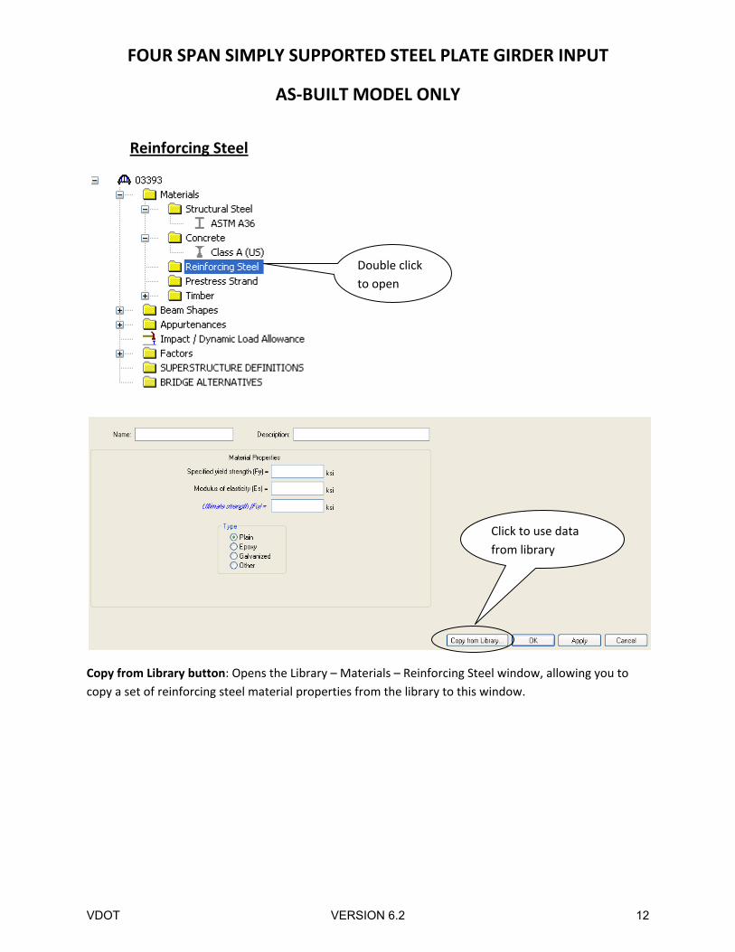
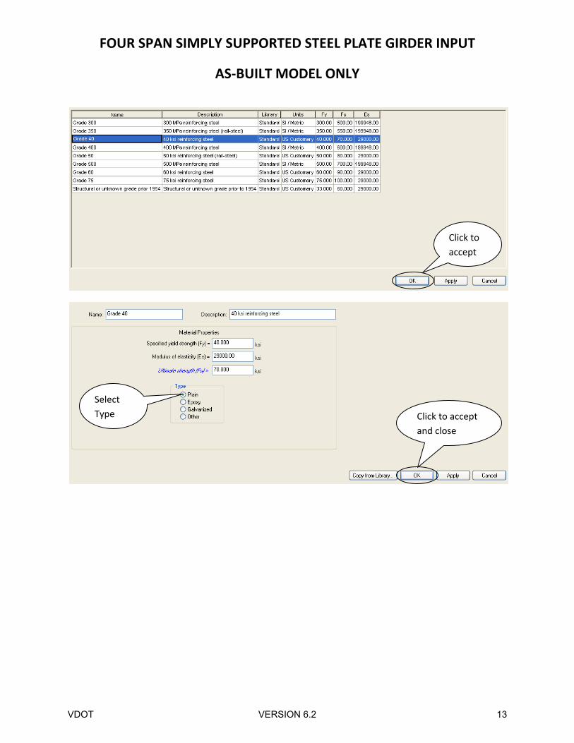
Reinforcing Steel
Copy from Library button: Opens the Library – Materials – Reinforcing Steel window, allowing you to
copy a set of reinforcing steel material properties from the library to this window.
Double click
to open
Click to use data
from library
VDOT VERSION 6.2 12
FOUR SPAN SIMPLY SUPPORTED STEEL PLATE GIRDER INPUT
AS‐BUILT MODEL ONLY
Click to
accept
Select
Type Click to accept
and close
VDOT VERSION 6.2 13
FOUR SPAN SIMPLY SUPPORTED STEEL PLATE GIRDER INPUT
AS‐BUILT MODEL ONLY
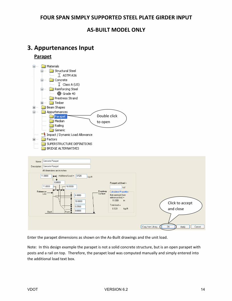
3. Appurtenances Input Parapet
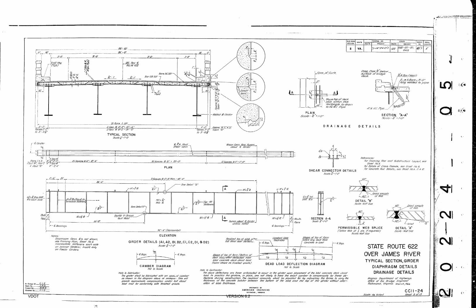
Enter the parapet dimensions as shown on the As‐Built drawings and the unit load.
Note: In this design example the parapet is not a solid concrete structure, but is an open parapet with
posts and a rail on top. Therefore, the parapet load was computed manually and simply entered into
the additional load text box.
Double click
to open
Click to accept
and close
VDOT VERSION 6.2 14
FOUR SPAN SIMPLY SUPPORTED STEEL PLATE GIRDER INPUT
AS‐BUILT MODEL ONLY
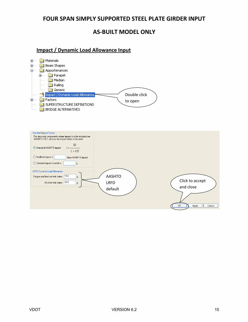
Impact / Dynamic Load Allowance Input
Double click
to open
AASHTO
LRFD
default
Click to accept
and close
VDOT VERSION 6.2 15
FOUR SPAN SIMPLY SUPPORTED STEEL PLATE GIRDER INPUT
AS‐BUILT MODEL ONLY
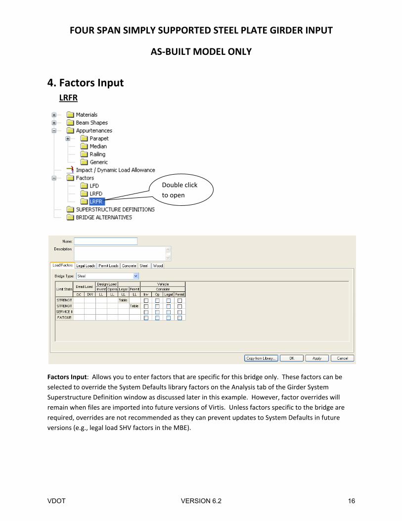
4. Factors Input LRFR
Factors Input: Allows you to enter factors that are specific for this bridge only. These factors can be
selected to override the System Defaults library factors on the Analysis tab of the Girder System
Superstructure Definition window as discussed later in this example. However, factor overrides will
remain when files are imported into future versions of Virtis. Unless factors specific to the bridge are
required, overrides are not recommended as they can prevent updates to System Defaults in future
versions (e.g., legal load SHV factors in the MBE).
Double click
to open
VDOT VERSION 6.2 16
FOUR SPAN SIMPLY SUPPORTED STEEL PLATE GIRDER INPUT
AS‐BUILT MODEL ONLY
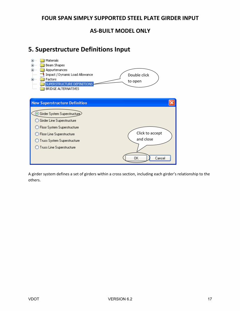
5. Superstructure Definitions Input
A girder system defines a set of girders within a cross section, including each girder’s relationship to the
others.
Double click
to open
Click to accept
and close
VDOT VERSION 6.2 17
FOUR SPAN SIMPLY SUPPORTED STEEL PLATE GIRDER INPUT
AS‐BUILT MODEL ONLY
Click to accept
and closeCenterline to
Centerline
Click to accept
and close
VDOT VERSION 6.2 18
FOUR SPAN SIMPLY SUPPORTED STEEL PLATE GIRDER INPUT
AS‐BUILT MODEL ONLY
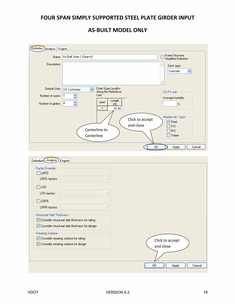
Factor Override: Allows you to use a set of factors that have been entered for this bridge only. These
factors allow you to override the System Defaults library factors with factors specific to this bridge.
Consider structural slab thickness for rating: Check this box if the structural slab thickness should be
used to compute section properties for rating. If this box is not checked, the rating will use section
properties computed from the total deck thickness.
Consider wearing surface for rating: Check this box if the wearing surface loads should be included for
rating.
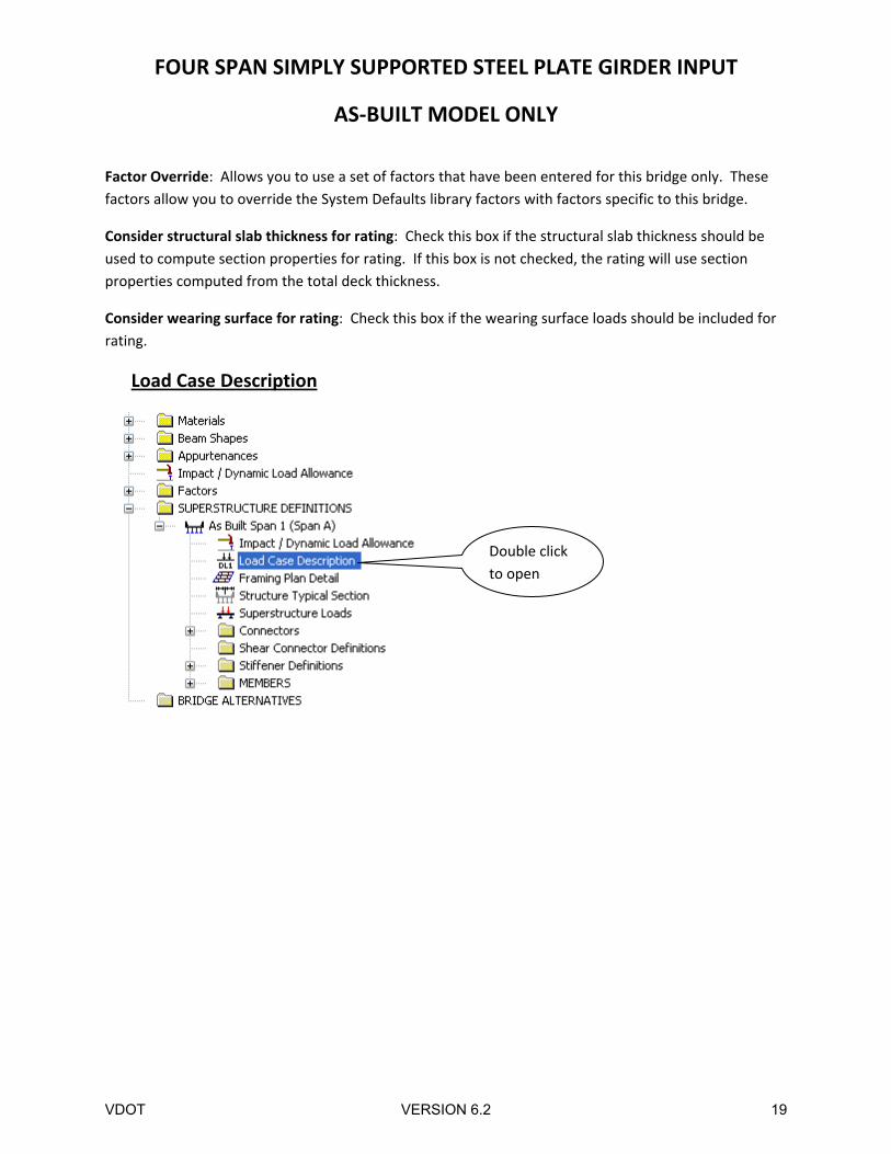
Load Case Description
Double click
to open
VDOT VERSION 6.2 19
FOUR SPAN SIMPLY SUPPORTED STEEL PLATE GIRDER INPUT
AS‐BUILT MODEL ONLY
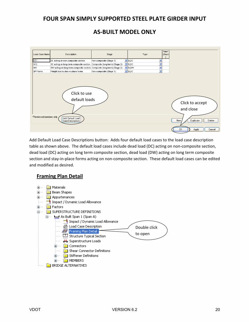
Add Default Load Case Descriptions button: Adds four default load cases to the load case description
table as shown above. The default load cases include dead load (DC) acting on non‐composite section,
dead load (DC) acting on long term composite section, dead load (DW) acting on long term composite
section and stay‐in‐place forms acting on non‐composite section. These default load cases can be edited
and modified as desired.
Framing Plan Detail
Click to accept
and close
Click to use
default loads
Double click
to open
VDOT VERSION 6.2 20
FOUR SPAN SIMPLY SUPPORTED STEEL PLATE GIRDER INPUT
AS‐BUILT MODEL ONLY
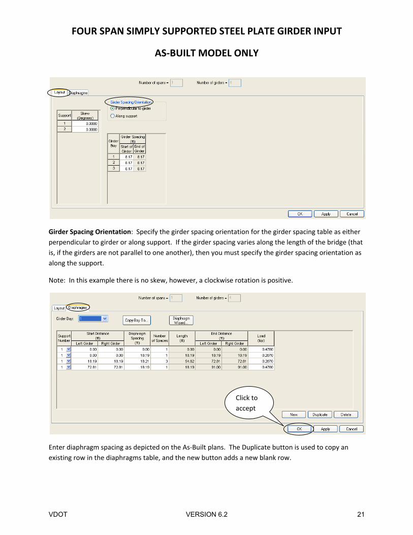
Girder Spacing Orientation: Specify the girder spacing orientation for the girder spacing table as either
perpendicular to girder or along support. If the girder spacing varies along the length of the bridge (that
is, if the girders are not parallel to one another), then you must specify the girder spacing orientation as
along the support.
Note: In this example there is no skew, however, a clockwise rotation is positive.
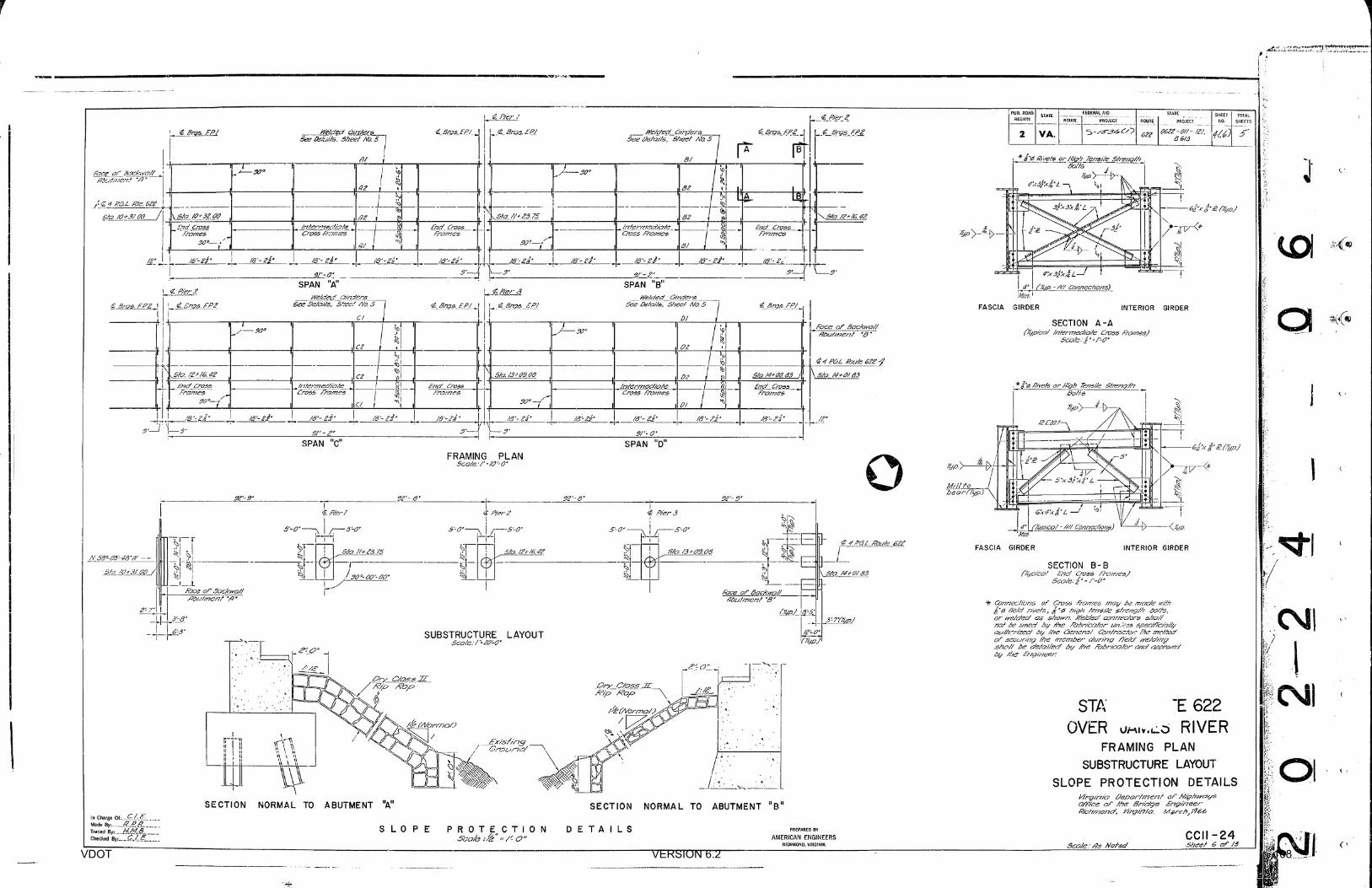
Enter diaphragm spacing as depicted on the As‐Built plans. The Duplicate button is used to copy an
existing row in the diaphragms table, and the new button adds a new blank row.
Click to
accept
VDOT VERSION 6.2 21
FOUR SPAN SIMPLY SUPPORTED STEEL PLATE GIRDER INPUT
AS‐BUILT MODEL ONLY
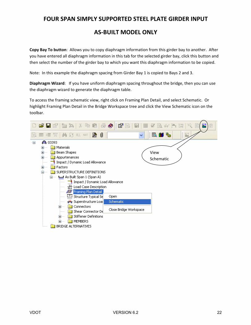
Copy Bay To button: Allows you to copy diaphragm information from this girder bay to another. After
you have entered all diaphragm information in this tab for the selected girder bay, click this button and
then select the number of the girder bay to which you want this diaphragm information to be copied.
Note: In this example the diaphragm spacing from Girder Bay 1 is copied to Bays 2 and 3.
Diaphragm Wizard: If you have uniform diaphragm spacing throughout the bridge, then you can use
the diaphragm wizard to generate the diaphragm table.
To access the framing schematic view, right click on Framing Plan Detail, and select Schematic. Or
highlight Framing Plan Detail in the Bridge Workspace tree and click the View Schematic icon on the
toolbar.
View
Schematic
VDOT VERSION 6.2 22
FOUR SPAN SIMPLY SUPPORTED STEEL PLATE GIRDER INPUT
AS‐BUILT MODEL ONLY
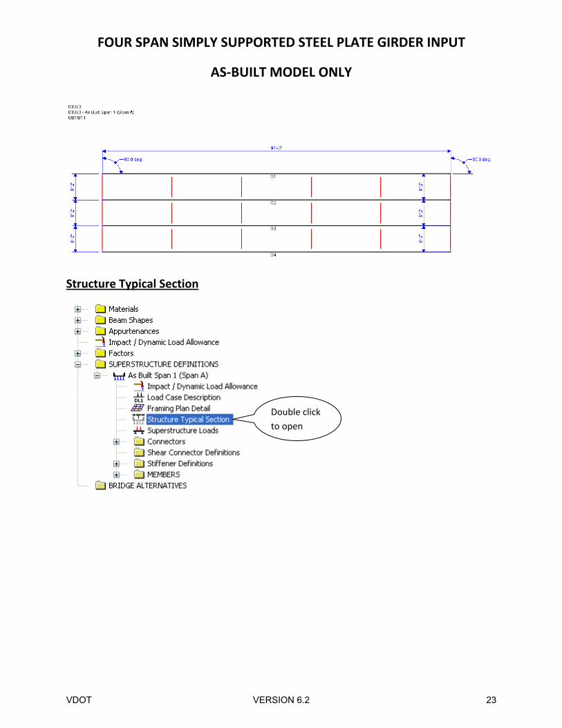
Structure Typical Section
Double click
to open
VDOT VERSION 6.2 23
FOUR SPAN SIMPLY SUPPORTED STEEL PLATE GIRDER INPUT
AS‐BUILT MODEL ONLY
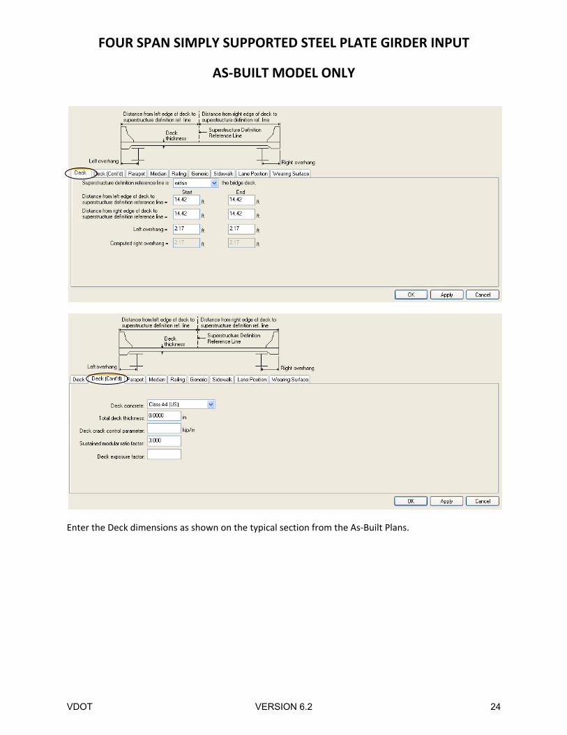
Enter the Deck dimensions as shown on the typical section from the As‐Built Plans.
VDOT VERSION 6.2 24
FOUR SPAN SIMPLY SUPPORTED STEEL PLATE GIRDER INPUT
AS‐BUILT MODEL ONLY
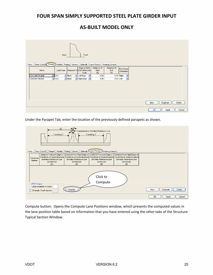
Under the Parapet Tab, enter the location of the previously defined parapets as shown.
Compute button: Opens the Compute Lane Positions window, which presents the computed values in
the lane position table based on information that you have entered using the other tabs of the Structure
Typical Section Window.
Click to
Compute
VDOT VERSION 6.2 25
FOUR SPAN SIMPLY SUPPORTED STEEL PLATE GIRDER INPUT
AS‐BUILT MODEL ONLY
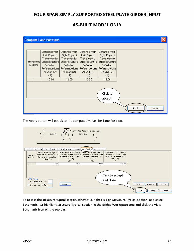
The Apply button will populate the computed values for Lane Position.
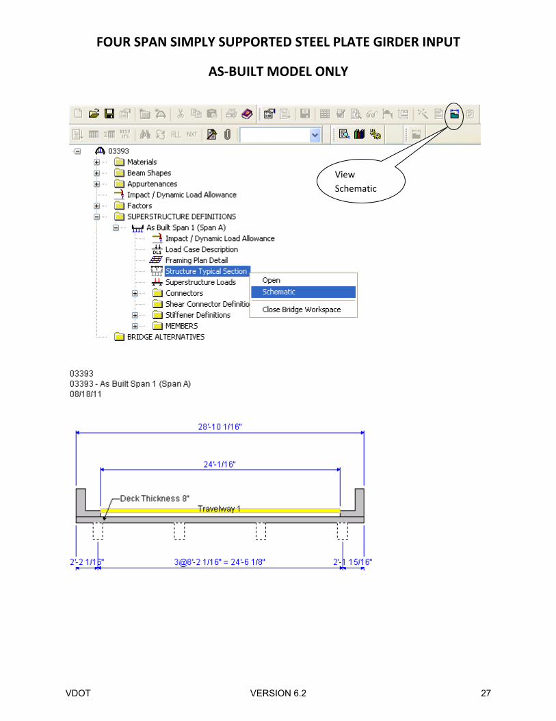
To access the structure typical section schematic, right click on Structure Typical Section, and select
Schematic. Or highlight Structure Typical Section in the Bridge Workspace tree and click the View
Schematic icon on the toolbar.
Click to
accept
Click to accept
and close
VDOT VERSION 6.2 26
FOUR SPAN SIMPLY SUPPORTED STEEL PLATE GIRDER INPUT
AS‐BUILT MODEL ONLY
View
Schematic
VDOT VERSION 6.2 27
FOUR SPAN SIMPLY SUPPORTED STEEL PLATE GIRDER INPUT
AS‐BUILT MODEL ONLY
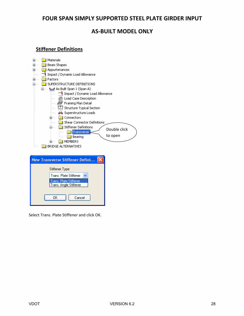
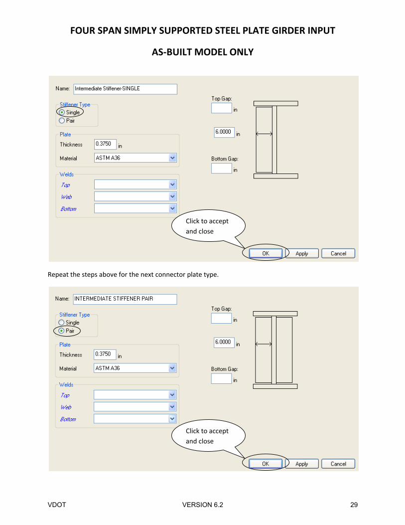
Stiffener Definitions
Select Trans. Plate Stiffener and click OK.
Double click
to open
VDOT VERSION 6.2 28
FOUR SPAN SIMPLY SUPPORTED STEEL PLATE GIRDER INPUT
AS‐BUILT MODEL ONLY
Repeat the steps above for the next connector plate type.
Click to accept
and close
Click to accept
and close
VDOT VERSION 6.2 29
FOUR SPAN SIMPLY SUPPORTED STEEL PLATE GIRDER INPUT
AS‐BUILT MODEL ONLY
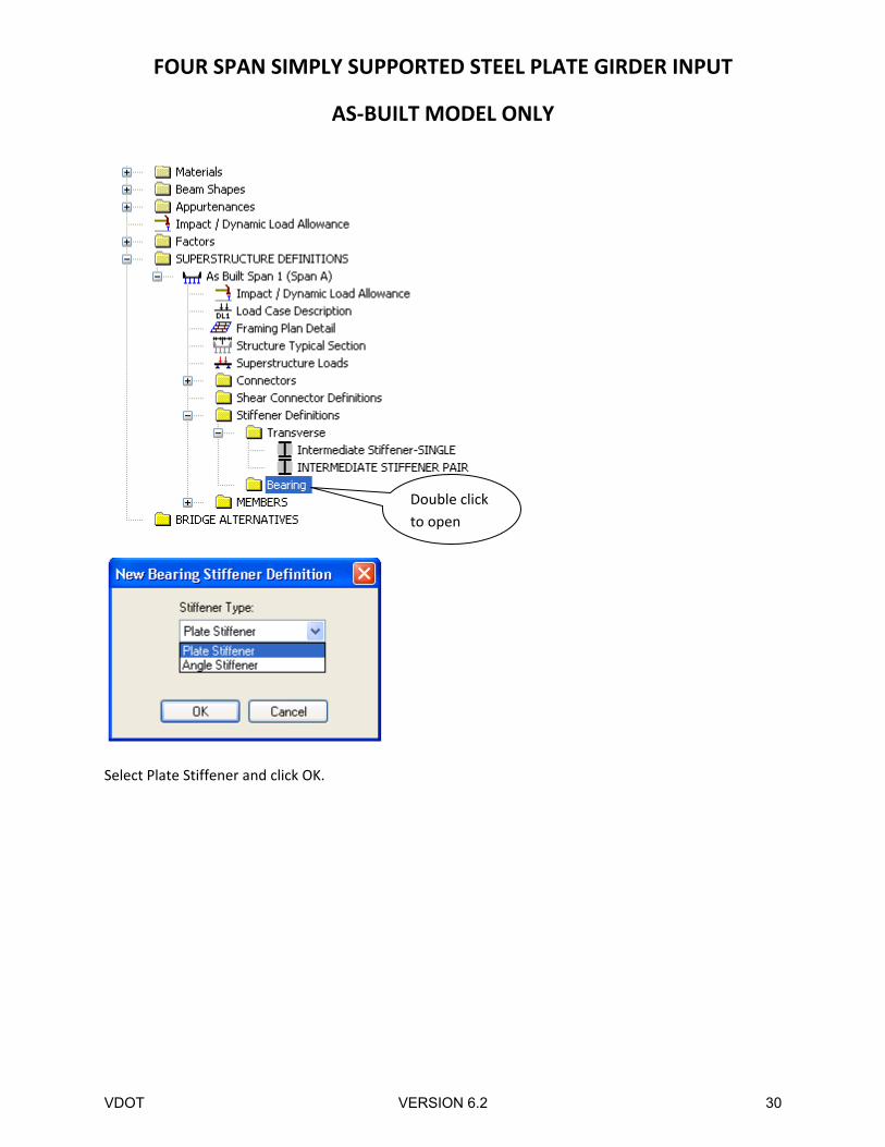
Select Plate Stiffener and click OK.
Double click
to open
VDOT VERSION 6.2 30
FOUR SPAN SIMPLY SUPPORTED STEEL PLATE GIRDER INPUT
AS‐BUILT MODEL ONLY
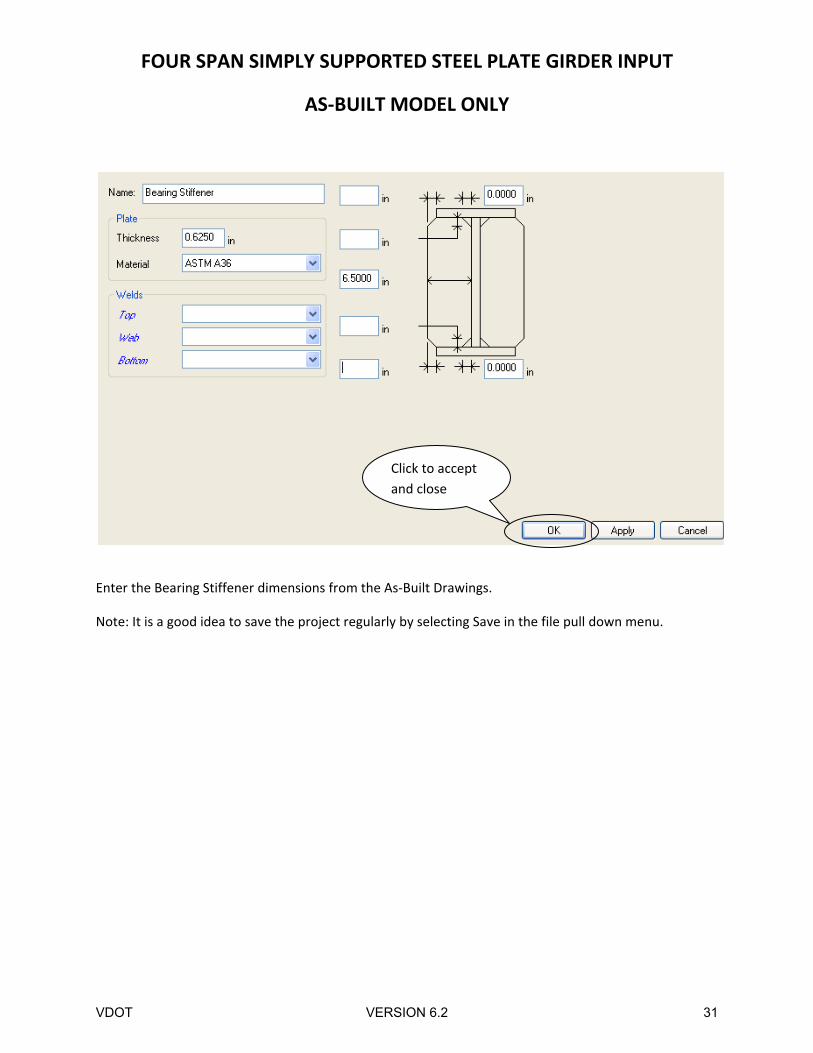
Enter the Bearing Stiffener dimensions from the As‐Built Drawings.
Note: It is a good idea to save the project regularly by selecting Save in the file pull down menu.
Click to accept
and close
VDOT VERSION 6.2 31
FOUR SPAN SIMPLY SUPPORTED STEEL PLATE GIRDER INPUT
AS‐BUILT MODEL ONLY
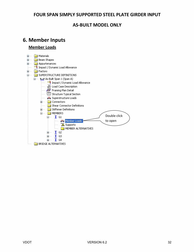
6. Member Inputs Member Loads
Double click
to open
VDOT VERSION 6.2 32
FOUR SPAN SIMPLY SUPPORTED STEEL PLATE GIRDER INPUT
AS‐BUILT MODEL ONLY
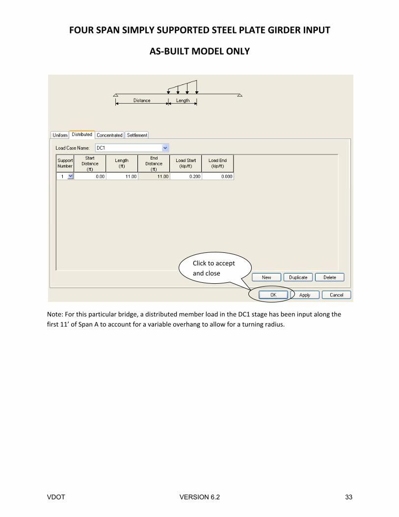
Note: For this particular bridge, a distributed member load in the DC1 stage has been input along the
first 11’ of Span A to account for a variable overhang to allow for a turning radius.
Click to accept
and close
VDOT VERSION 6.2 33
FOUR SPAN SIMPLY SUPPORTED STEEL PLATE GIRDER INPUT
AS‐BUILT MODEL ONLY
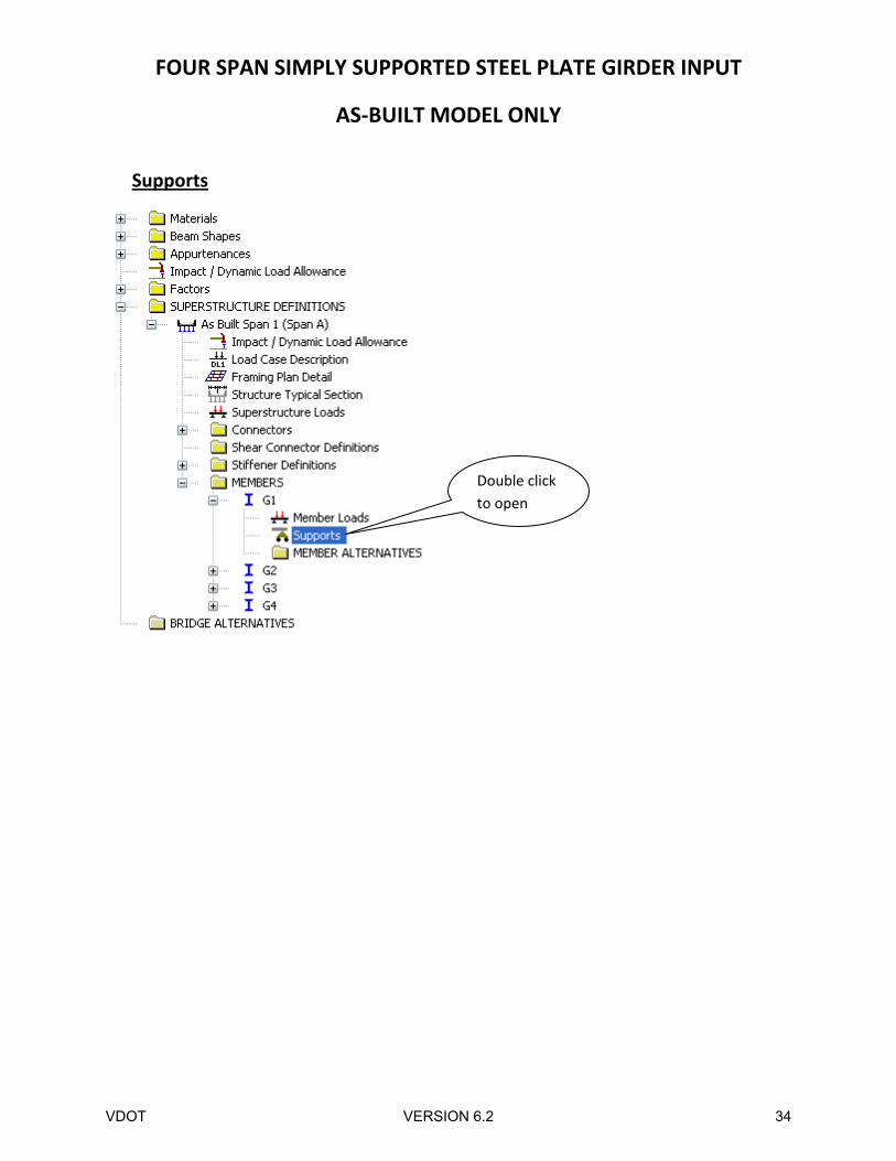
Supports
Double click
to open
VDOT VERSION 6.2 34
FOUR SPAN SIMPLY SUPPORTED STEEL PLATE GIRDER INPUT
AS‐BUILT MODEL ONLY
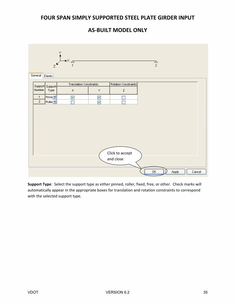
Support Type: Select the support type as either pinned, roller, fixed, free, or other. Check marks will
automatically appear in the appropriate boxes for translation and rotation constraints to correspond
with the selected support type.
Click to accept
and close
VDOT VERSION 6.2 35
FOUR SPAN SIMPLY SUPPORTED STEEL PLATE GIRDER INPUT
AS‐BUILT MODEL ONLY
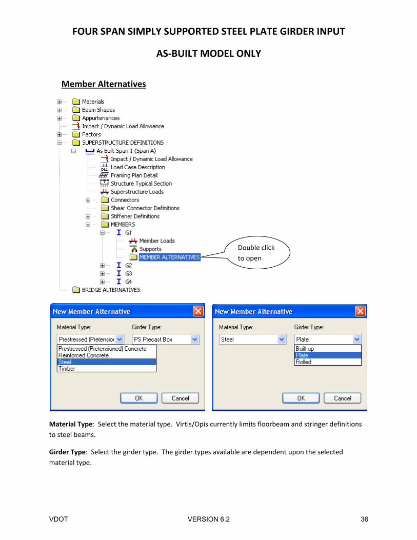
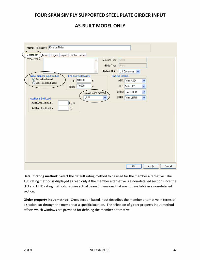
Member Alternatives
Material Type: Select the material type. Virtis/Opis currently limits floorbeam and stringer definitions
to steel beams.
Girder Type: Select the girder type. The girder types available are dependent upon the selected
material type.
Double click
to open
VDOT VERSION 6.2 36
FOUR SPAN SIMPLY SUPPORTED STEEL PLATE GIRDER INPUT
AS‐BUILT MODEL ONLY
Default rating method: Select the default rating method to be used for the member alternative. The
ASD rating method is displayed as read only if the member alternative is a non‐detailed section since the
LFD and LRFD rating methods require actual beam dimensions that are not available in a non‐detailed
section.
Girder property input method: Cross‐section based input describes the member alternative in terms of
a section cut through the member at a specific location. The selection of girder property input method
affects which windows are provided for defining the member alternative.
VDOT VERSION 6.2 37
FOUR SPAN SIMPLY SUPPORTED STEEL PLATE GIRDER INPUT
AS‐BUILT MODEL ONLY
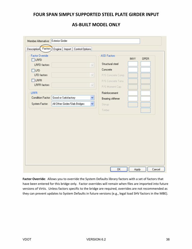
Factor Override: Allows you to override the System Defaults library factors with a set of factors that
have been entered for this bridge only. Factor overrides will remain when files are imported into future
versions of Virtis. Unless factors specific to the bridge are required, overrides are not recommended as
they can prevent updates to System Defaults in future versions (e.g., legal load SHV factors in the MBE).
VDOT VERSION 6.2 38
FOUR SPAN SIMPLY SUPPORTED STEEL PLATE GIRDER INPUT
AS‐BUILT MODEL ONLY
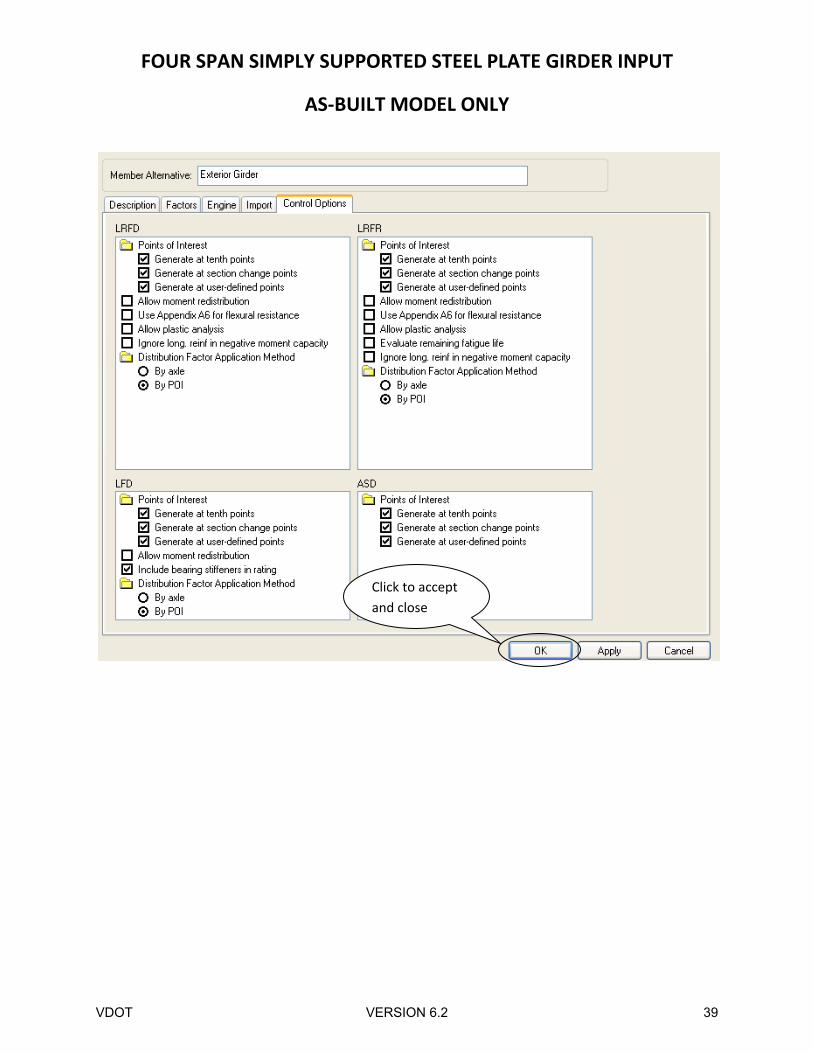
Click to accept
and close
VDOT VERSION 6.2 39
FOUR SPAN SIMPLY SUPPORTED STEEL PLATE GIRDER INPUT
AS‐BUILT MODEL ONLY
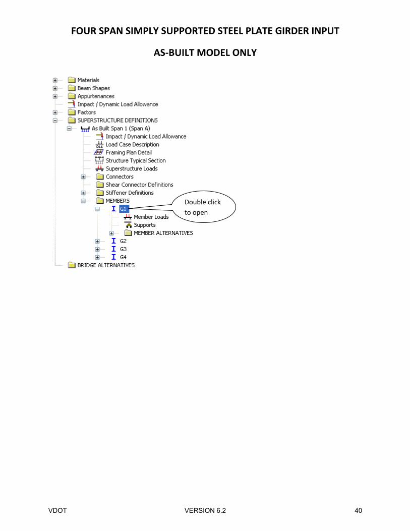
Double click
to open
VDOT VERSION 6.2 40
FOUR SPAN SIMPLY SUPPORTED STEEL PLATE GIRDER INPUT
AS‐BUILT MODEL ONLY
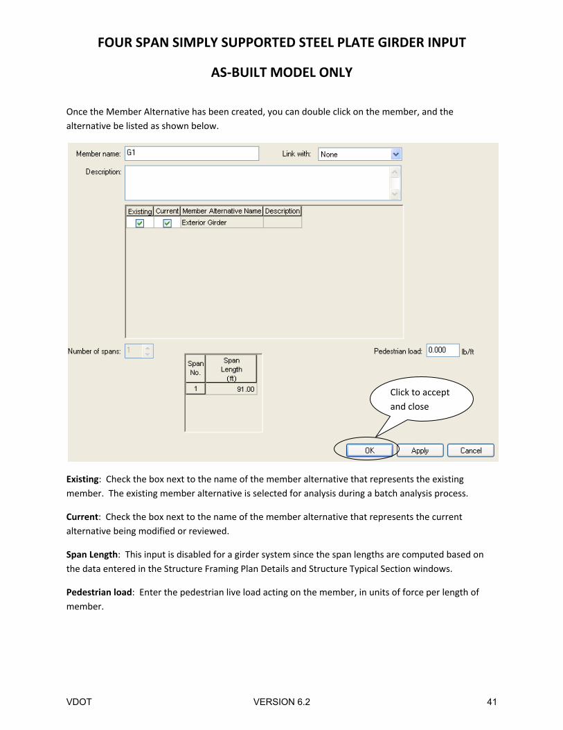
Once the Member Alternative has been created, you can double click on the member, and the
alternative be listed as shown below.
Existing: Check the box next to the name of the member alternative that represents the existing
member. The existing member alternative is selected for analysis during a batch analysis process.
Current: Check the box next to the name of the member alternative that represents the current
alternative being modified or reviewed.
Span Length: This input is disabled for a girder system since the span lengths are computed based on
the data entered in the Structure Framing Plan Details and Structure Typical Section windows.
Pedestrian load: Enter the pedestrian live load acting on the member, in units of force per length of
member.
Click to accept
and close
VDOT VERSION 6.2 41
FOUR SPAN SIMPLY SUPPORTED STEEL PLATE GIRDER INPUT
AS‐BUILT MODEL ONLY
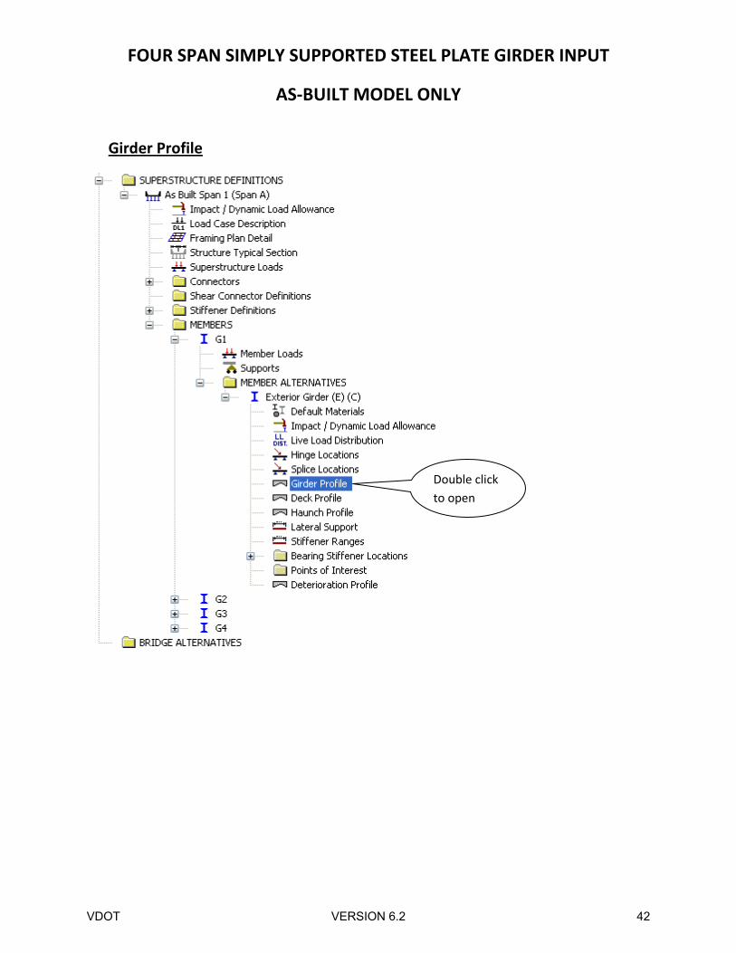
Girder Profile
Double click
to open
VDOT VERSION 6.2 42
FOUR SPAN SIMPLY SUPPORTED STEEL PLATE GIRDER INPUT
AS‐BUILT MODEL ONLY
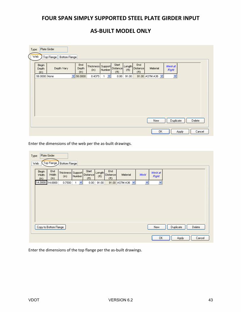
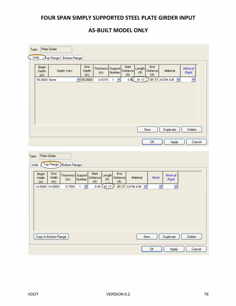
Enter the dimensions of the web per the as‐built drawings.
Enter the dimensions of the top flange per the as‐built drawings.
VDOT VERSION 6.2 43
FOUR SPAN SIMPLY SUPPORTED STEEL PLATE GIRDER INPUT
AS‐BUILT MODEL ONLY
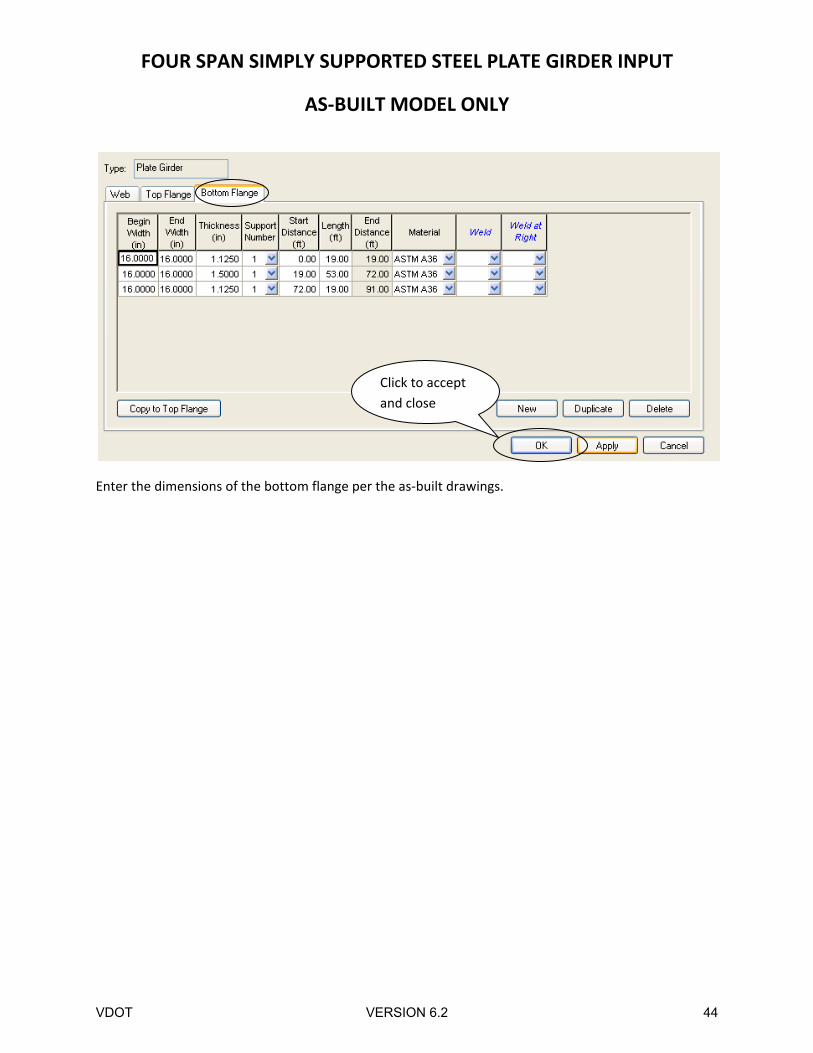
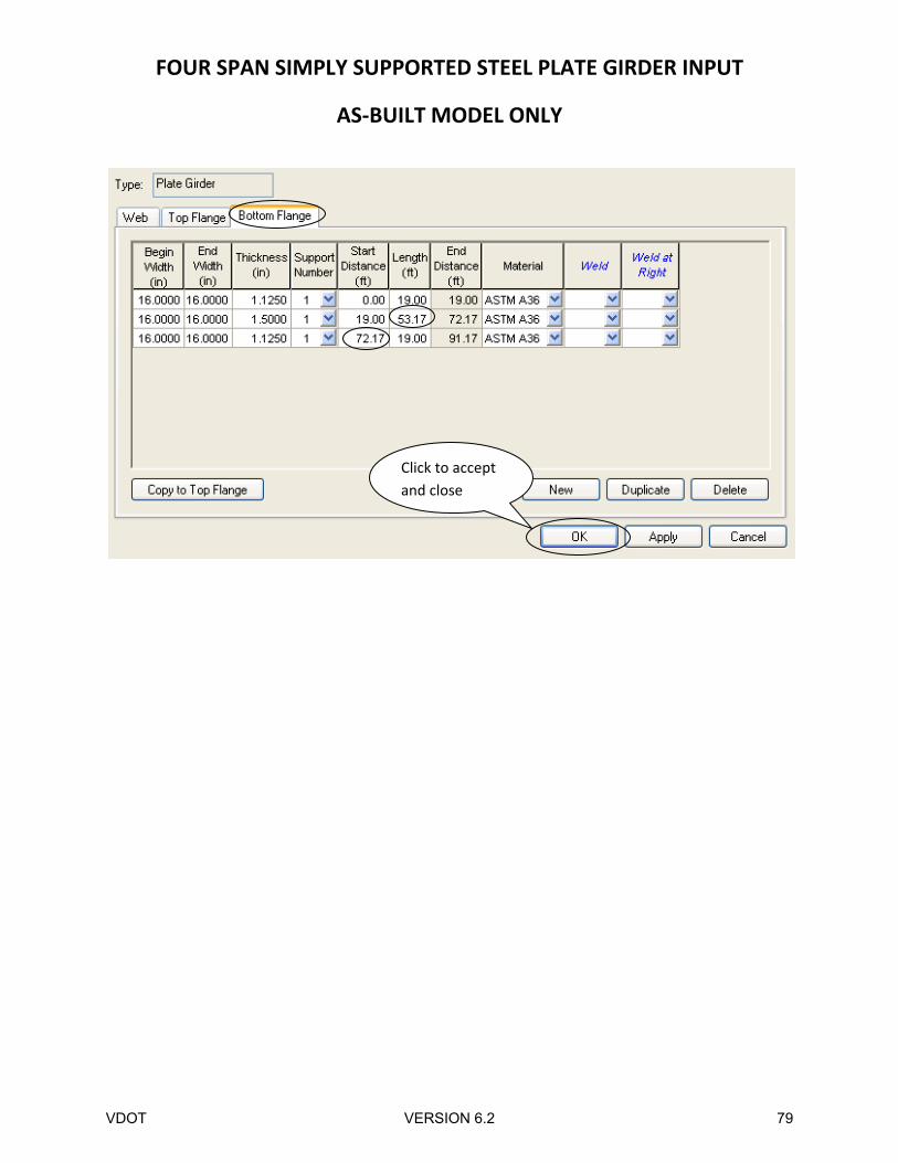
Enter the dimensions of the bottom flange per the as‐built drawings.
Click to accept
and close
VDOT VERSION 6.2 44
FOUR SPAN SIMPLY SUPPORTED STEEL PLATE GIRDER INPUT
AS‐BUILT MODEL ONLY
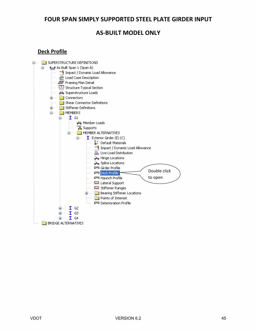
Deck Profile
Double click
to open
VDOT VERSION 6.2 45
FOUR SPAN SIMPLY SUPPORTED STEEL PLATE GIRDER INPUT
AS‐BUILT MODEL ONLY
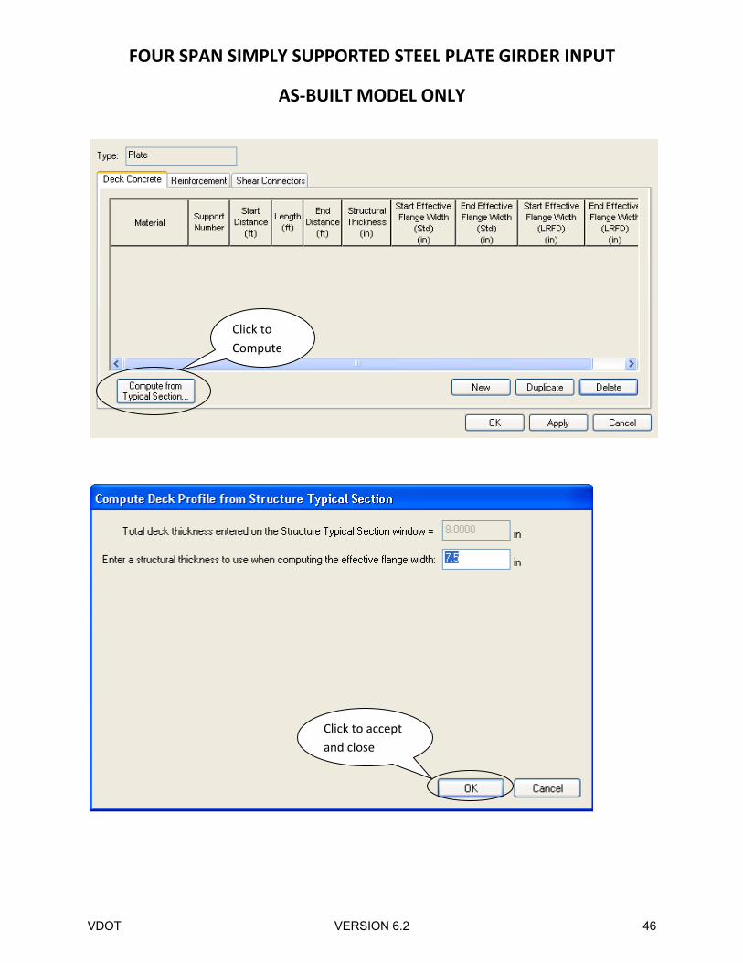
Click to
Compute
Click to accept
and close
VDOT VERSION 6.2 46
FOUR SPAN SIMPLY SUPPORTED STEEL PLATE GIRDER INPUT
AS‐BUILT MODEL ONLY
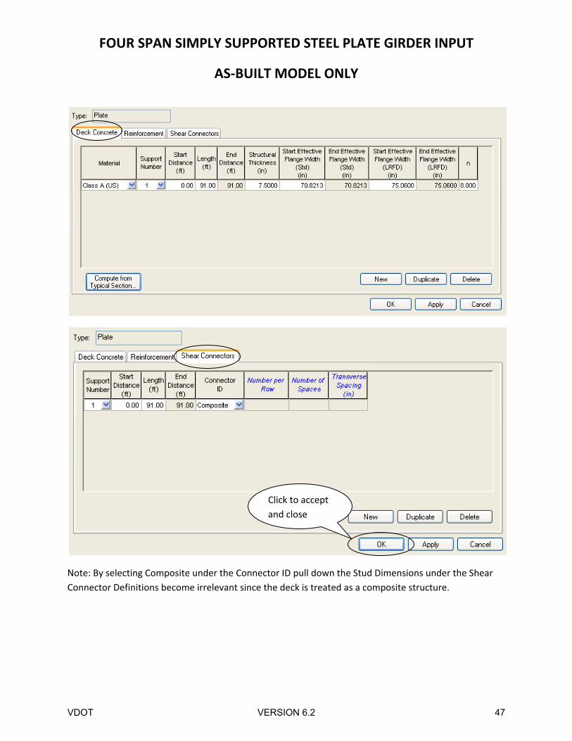
Note: By selecting Composite under the Connector ID pull down the Stud Dimensions under the Shear
Connector Definitions become irrelevant since the deck is treated as a composite structure.
Click to accept
and close
VDOT VERSION 6.2 47
FOUR SPAN SIMPLY SUPPORTED STEEL PLATE GIRDER INPUT
AS‐BUILT MODEL ONLY
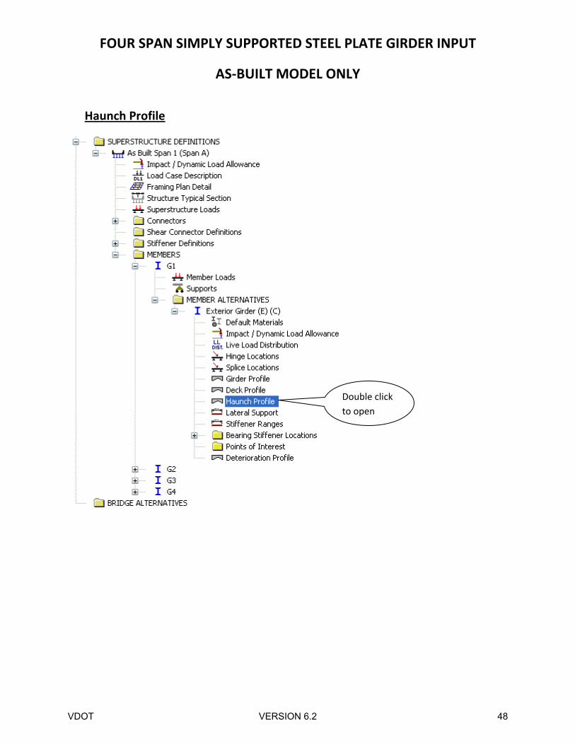
Haunch Profile
Double click
to open
VDOT VERSION 6.2 48
FOUR SPAN SIMPLY SUPPORTED STEEL PLATE GIRDER INPUT
AS‐BUILT MODEL ONLY
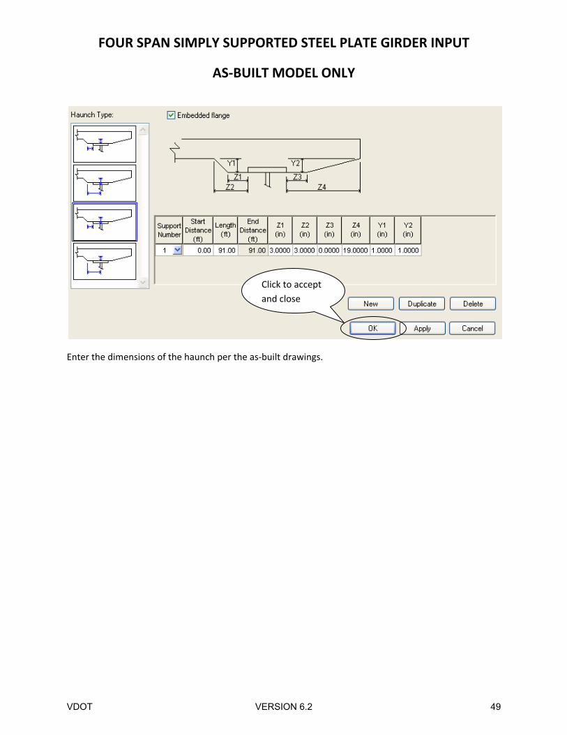
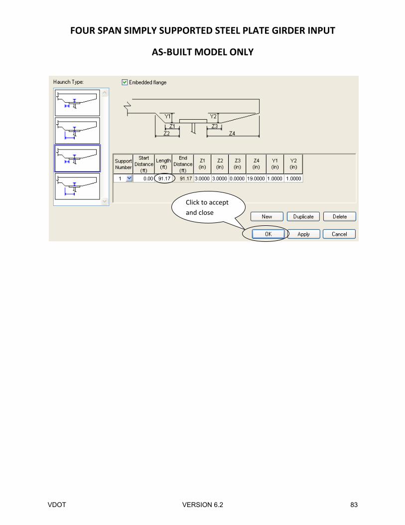
Enter the dimensions of the haunch per the as‐built drawings.
Click to accept
and close
VDOT VERSION 6.2 49
FOUR SPAN SIMPLY SUPPORTED STEEL PLATE GIRDER INPUT
AS‐BUILT MODEL ONLY
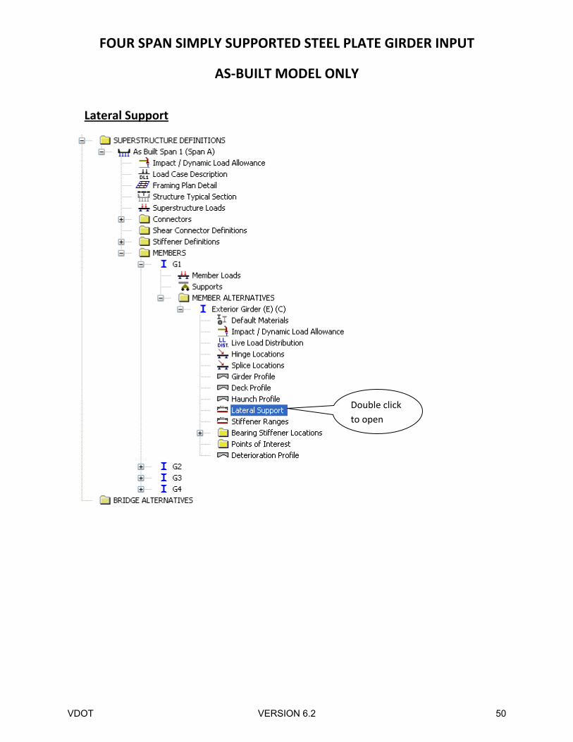
Lateral Support
Double click
to open
VDOT VERSION 6.2 50
FOUR SPAN SIMPLY SUPPORTED STEEL PLATE GIRDER INPUT
AS‐BUILT MODEL ONLY
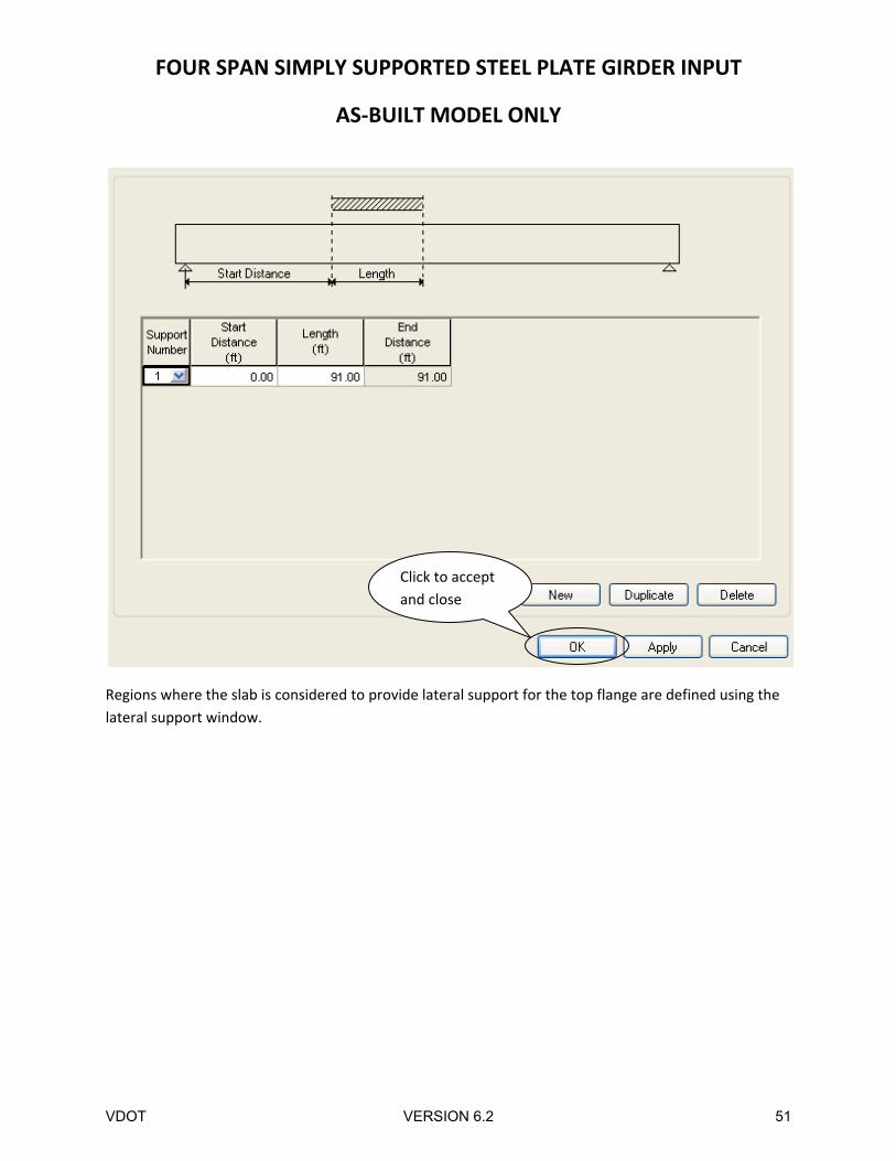
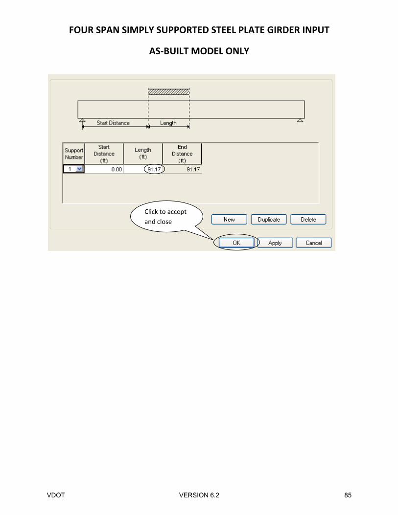
Regions where the slab is considered to provide lateral support for the top flange are defined using the
lateral support window.
Click to accept
and close
VDOT VERSION 6.2 51
FOUR SPAN SIMPLY SUPPORTED STEEL PLATE GIRDER INPUT
AS‐BUILT MODEL ONLY
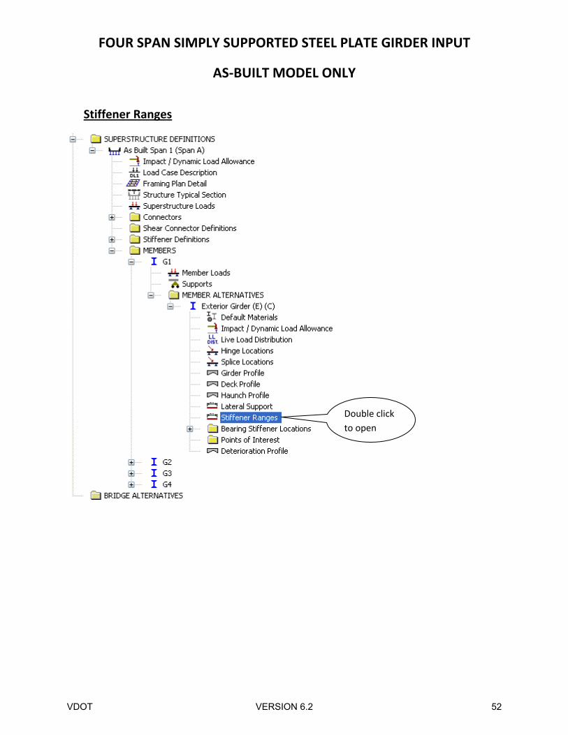
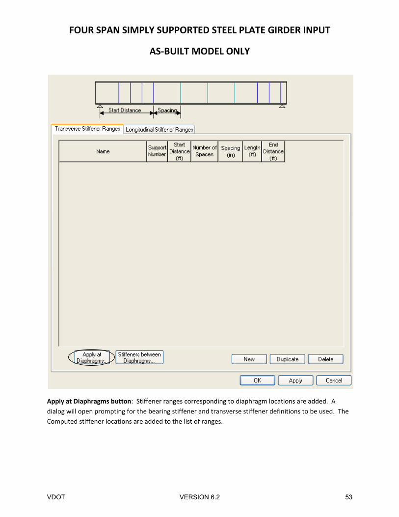
Stiffener Ranges
Double click
to open
VDOT VERSION 6.2 52
FOUR SPAN SIMPLY SUPPORTED STEEL PLATE GIRDER INPUT
AS‐BUILT MODEL ONLY
Apply at Diaphragms button: Stiffener ranges corresponding to diaphragm locations are added. A
dialog will open prompting for the bearing stiffener and transverse stiffener definitions to be used. The
Computed stiffener locations are added to the list of ranges.
VDOT VERSION 6.2 53
FOUR SPAN SIMPLY SUPPORTED STEEL PLATE GIRDER INPUT
AS‐BUILT MODEL ONLY
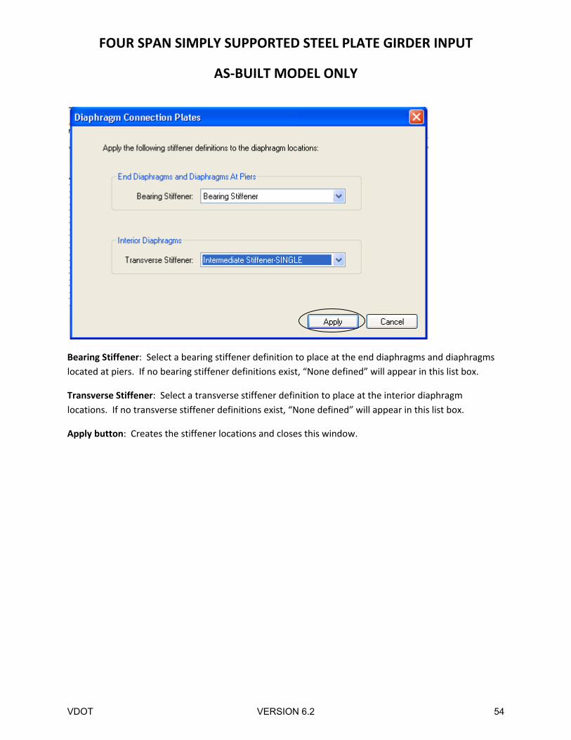
Bearing Stiffener: Select a bearing stiffener definition to place at the end diaphragms and diaphragms
located at piers. If no bearing stiffener definitions exist, “None defined” will appear in this list box.
Transverse Stiffener: Select a transverse stiffener definition to place at the interior diaphragm
locations. If no transverse stiffener definitions exist, “None defined” will appear in this list box.
Apply button: Creates the stiffener locations and closes this window.
VDOT VERSION 6.2 54
FOUR SPAN SIMPLY SUPPORTED STEEL PLATE GIRDER INPUT
AS‐BUILT MODEL ONLY
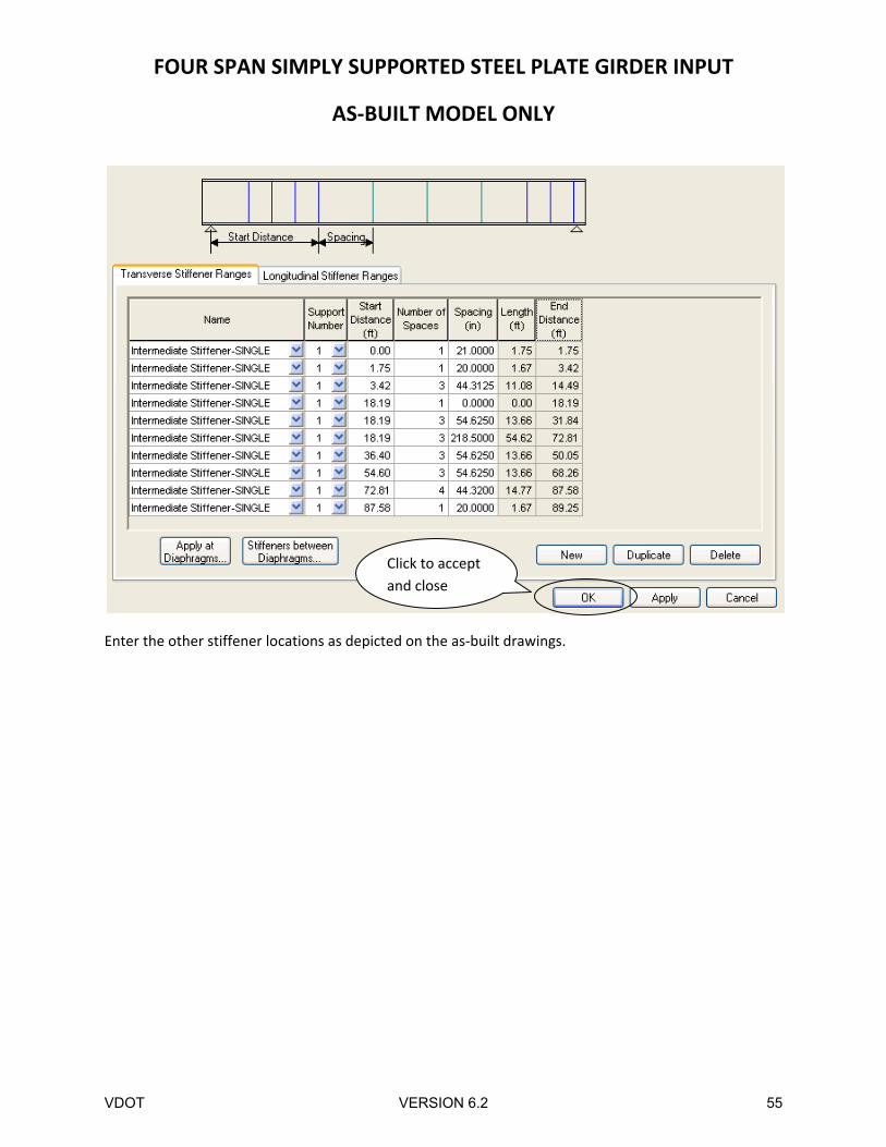
Enter the other stiffener locations as depicted on the as‐built drawings.
Click to accept
and close
VDOT VERSION 6.2 55
FOUR SPAN SIMPLY SUPPORTED STEEL PLATE GIRDER INPUT
AS‐BUILT MODEL ONLY
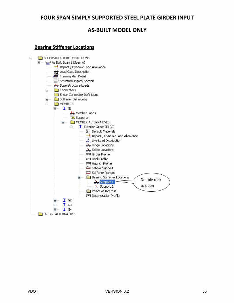
Bearing Stiffener Locations
Double click
to open
VDOT VERSION 6.2 56
FOUR SPAN SIMPLY SUPPORTED STEEL PLATE GIRDER INPUT
AS‐BUILT MODEL ONLY
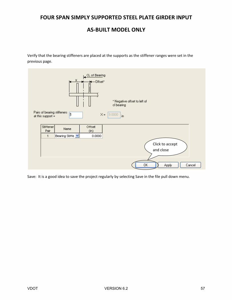
Verify that the bearing stiffeners are placed at the supports as the stiffener ranges were set in the
previous page.
Save: It is a good idea to save the project regularly by selecting Save in the file pull down menu.
Click to accept
and close
VDOT VERSION 6.2 57
FOUR SPAN SIMPLY SUPPORTED STEEL PLATE GIRDER INPUT
AS‐BUILT MODEL ONLY
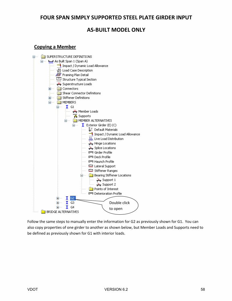
Copying a Member
Follow the same steps to manually enter the information for G2 as previously shown for G1. You can
also copy properties of one girder to another as shown below, but Member Loads and Supports need to
be defined as previously shown for G1 with interior loads.
Double click
to open
VDOT VERSION 6.2 58
FOUR SPAN SIMPLY SUPPORTED STEEL PLATE GIRDER INPUT
AS‐BUILT MODEL ONLY
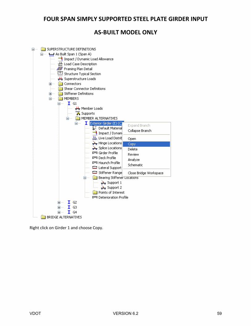
Right click on Girder 1 and choose Copy.
VDOT VERSION 6.2 59
FOUR SPAN SIMPLY SUPPORTED STEEL PLATE GIRDER INPUT
AS‐BUILT MODEL ONLY
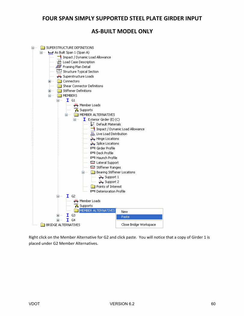
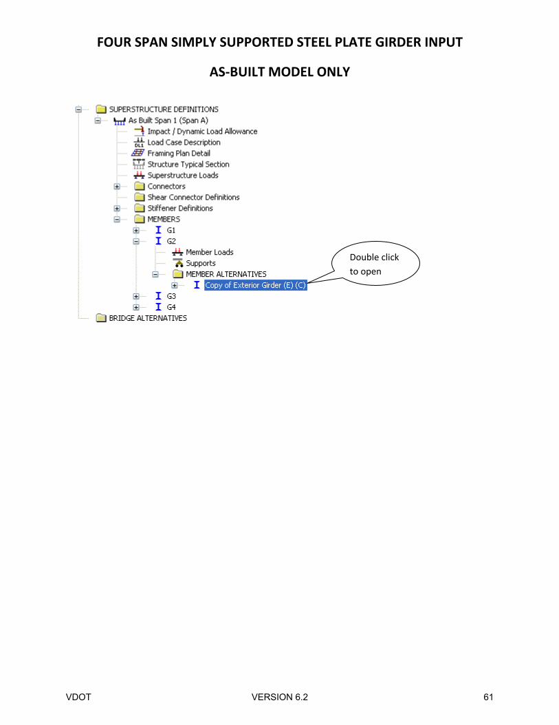
Right click on the Member Alternative for G2 and click paste. You will notice that a copy of Girder 1 is
placed under G2 Member Alternatives.
VDOT VERSION 6.2 60
FOUR SPAN SIMPLY SUPPORTED STEEL PLATE GIRDER INPUT
AS‐BUILT MODEL ONLY
Double click
to open
VDOT VERSION 6.2 61
FOUR SPAN SIMPLY SUPPORTED STEEL PLATE GIRDER INPUT
AS‐BUILT MODEL ONLY
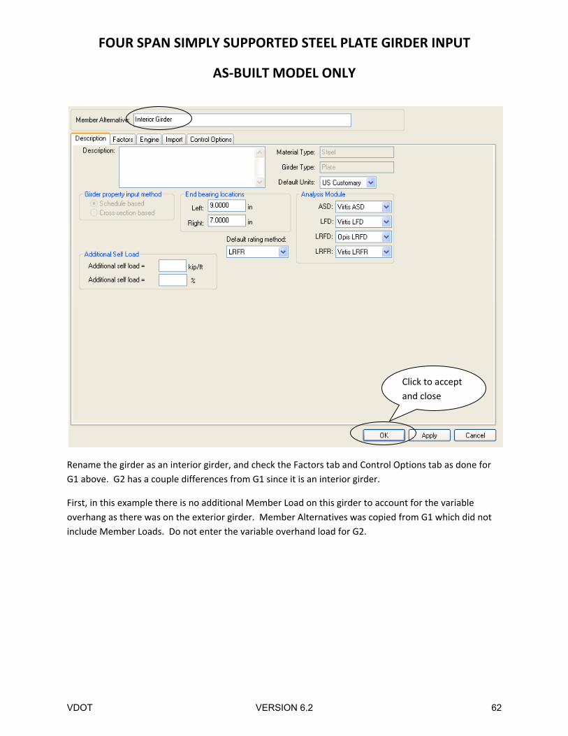
Rename the girder as an interior girder, and check the Factors tab and Control Options tab as done for
G1 above. G2 has a couple differences from G1 since it is an interior girder.
First, in this example there is no additional Member Load on this girder to account for the variable
overhang as there was on the exterior girder. Member Alternatives was copied from G1 which did not
include Member Loads. Do not enter the variable overhand load for G2.
Click to accept
and close
VDOT VERSION 6.2 62
FOUR SPAN SIMPLY SUPPORTED STEEL PLATE GIRDER INPUT
AS‐BUILT MODEL ONLY
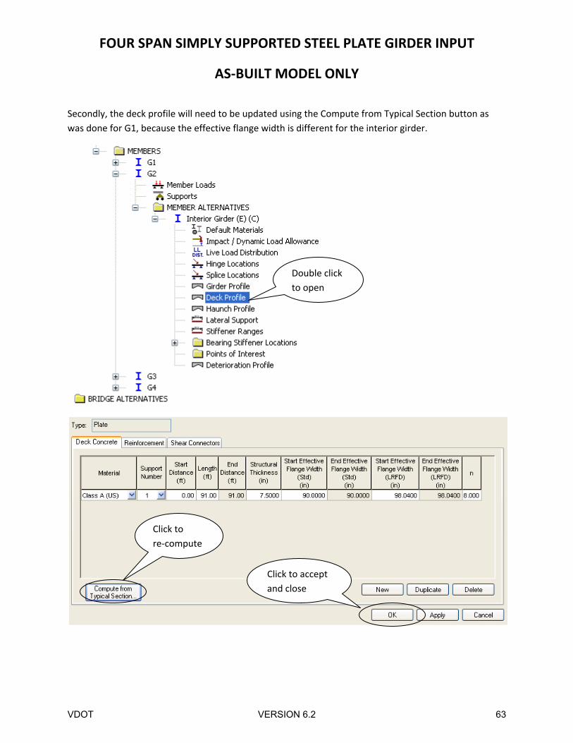
Secondly, the deck profile will need to be updated using the Compute from Typical Section button as
was done for G1, because the effective flange width is different for the interior girder.
Double click
to open
Click to accept
and close
Click to
re‐compute
VDOT VERSION 6.2 63
FOUR SPAN SIMPLY SUPPORTED STEEL PLATE GIRDER INPUT
AS‐BUILT MODEL ONLY
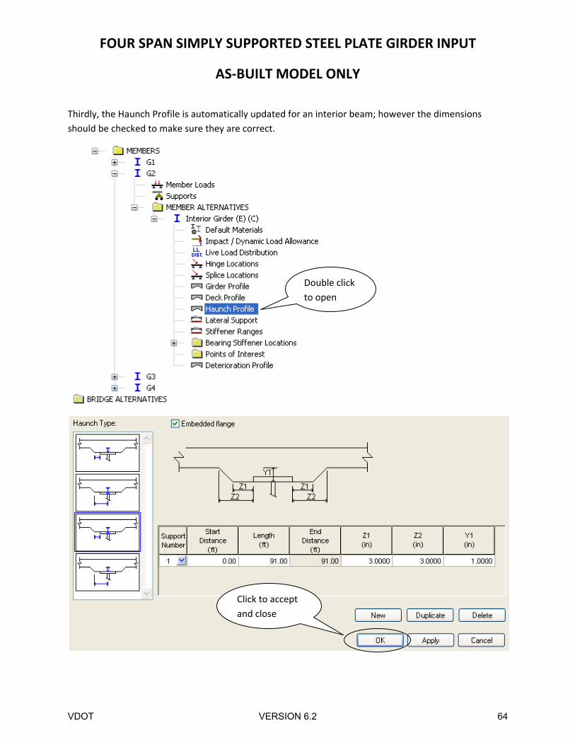
Thirdly, the Haunch Profile is automatically updated for an interior beam; however the dimensions
should be checked to make sure they are correct.
Click to accept
and close
Double click
to open
VDOT VERSION 6.2 64
FOUR SPAN SIMPLY SUPPORTED STEEL PLATE GIRDER INPUT
AS‐BUILT MODEL ONLY
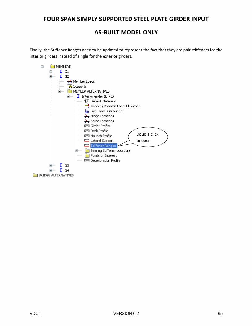
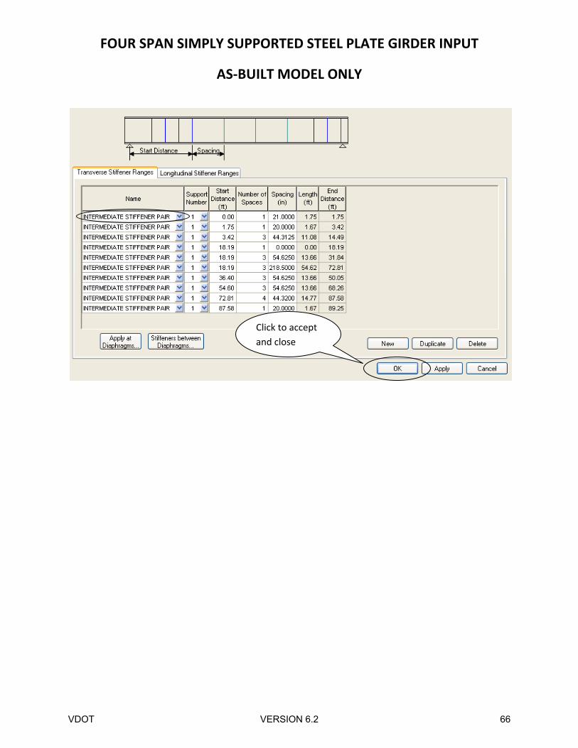
Finally, the Stiffener Ranges need to be updated to represent the fact that they are pair stiffeners for the
interior girders instead of single for the exterior girders.
Double click
to open
VDOT VERSION 6.2 65
FOUR SPAN SIMPLY SUPPORTED STEEL PLATE GIRDER INPUT
AS‐BUILT MODEL ONLY
Click to accept
and close
VDOT VERSION 6.2 66
FOUR SPAN SIMPLY SUPPORTED STEEL PLATE GIRDER INPUT
AS‐BUILT MODEL ONLY
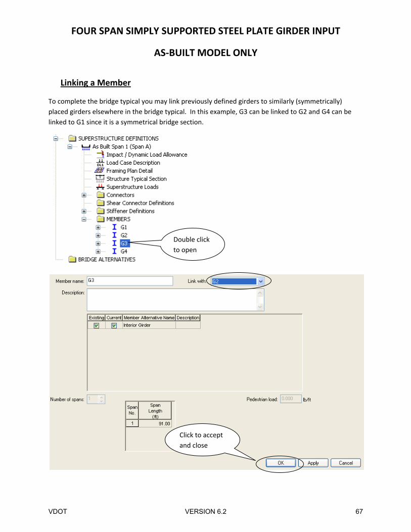
Linking a Member
To complete the bridge typical you may link previously defined girders to similarly (symmetrically)
placed girders elsewhere in the bridge typical. In this example, G3 can be linked to G2 and G4 can be
linked to G1 since it is a symmetrical bridge section.
Double click
to open
Click to accept
and close
VDOT VERSION 6.2 67
FOUR SPAN SIMPLY SUPPORTED STEEL PLATE GIRDER INPUT
AS‐BUILT MODEL ONLY
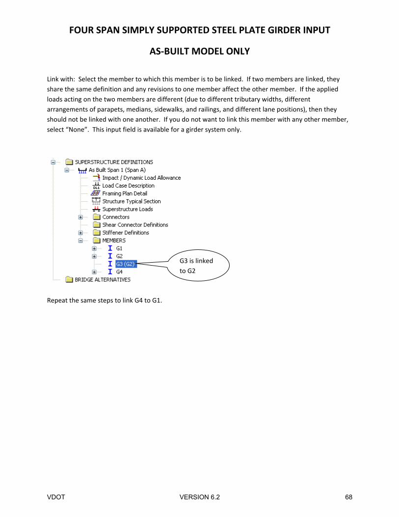
Link with: Select the member to which this member is to be linked. If two members are linked, they
share the same definition and any revisions to one member affect the other member. If the applied
loads acting on the two members are different (due to different tributary widths, different
arrangements of parapets, medians, sidewalks, and railings, and different lane positions), then they
should not be linked with one another. If you do not want to link this member with any other member,
select “None”. This input field is available for a girder system only.
Repeat the same steps to link G4 to G1.
G3 is linked
to G2
VDOT VERSION 6.2 68
FOUR SPAN SIMPLY SUPPORTED STEEL PLATE GIRDER INPUT
AS‐BUILT MODEL ONLY
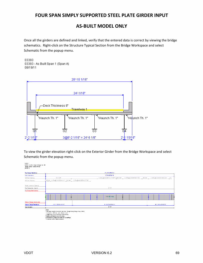
Once all the girders are defined and linked, verify that the entered data is correct by viewing the bridge
schematics. Right‐click on the Structure Typical Section from the Bridge Workspace and select
Schematic from the popup menu.
To view the girder elevation right‐click on the Exterior Girder from the Bridge Workspace and select
Schematic from the popup menu.
VDOT VERSION 6.2 69
FOUR SPAN SIMPLY SUPPORTED STEEL PLATE GIRDER INPUT
AS‐BUILT MODEL ONLY
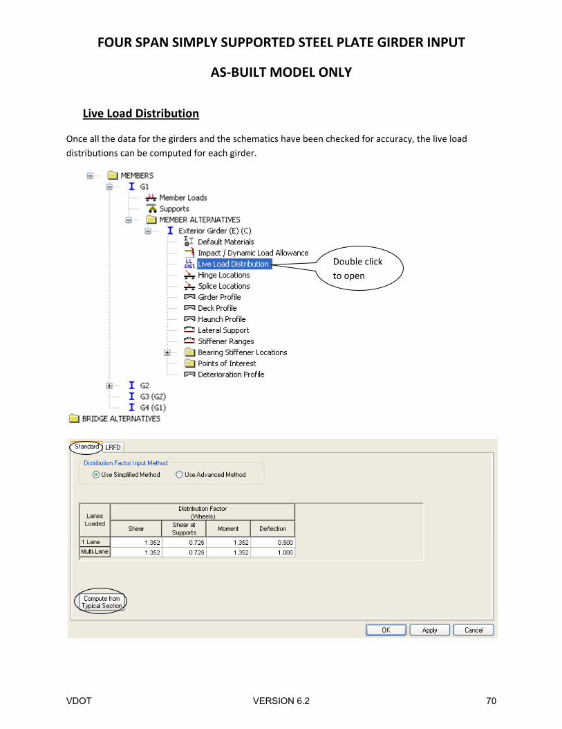
Live Load Distribution
Once all the data for the girders and the schematics have been checked for accuracy, the live load
distributions can be computed for each girder.
Double click
to open
VDOT VERSION 6.2 70
FOUR SPAN SIMPLY SUPPORTED STEEL PLATE GIRDER INPUT
AS‐BUILT MODEL ONLY
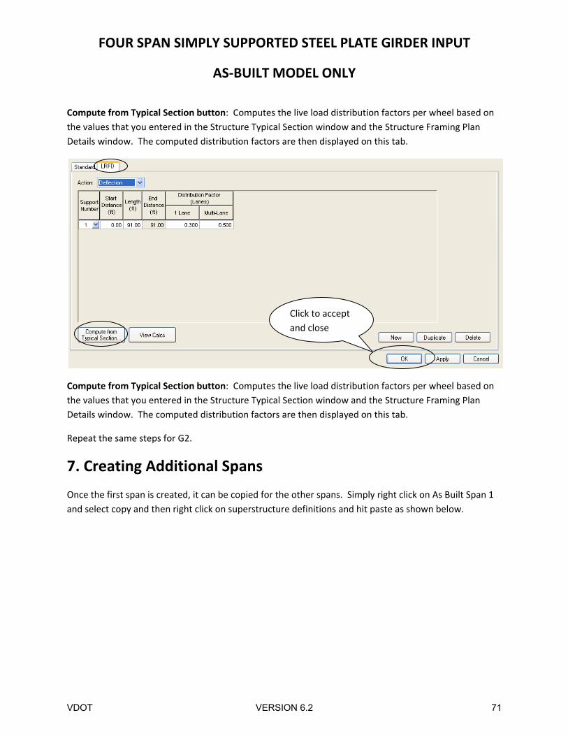
Compute from Typical Section button: Computes the live load distribution factors per wheel based on
the values that you entered in the Structure Typical Section window and the Structure Framing Plan
Details window. The computed distribution factors are then displayed on this tab.
Compute from Typical Section button: Computes the live load distribution factors per wheel based on
the values that you entered in the Structure Typical Section window and the Structure Framing Plan
Details window. The computed distribution factors are then displayed on this tab.
Repeat the same steps for G2.
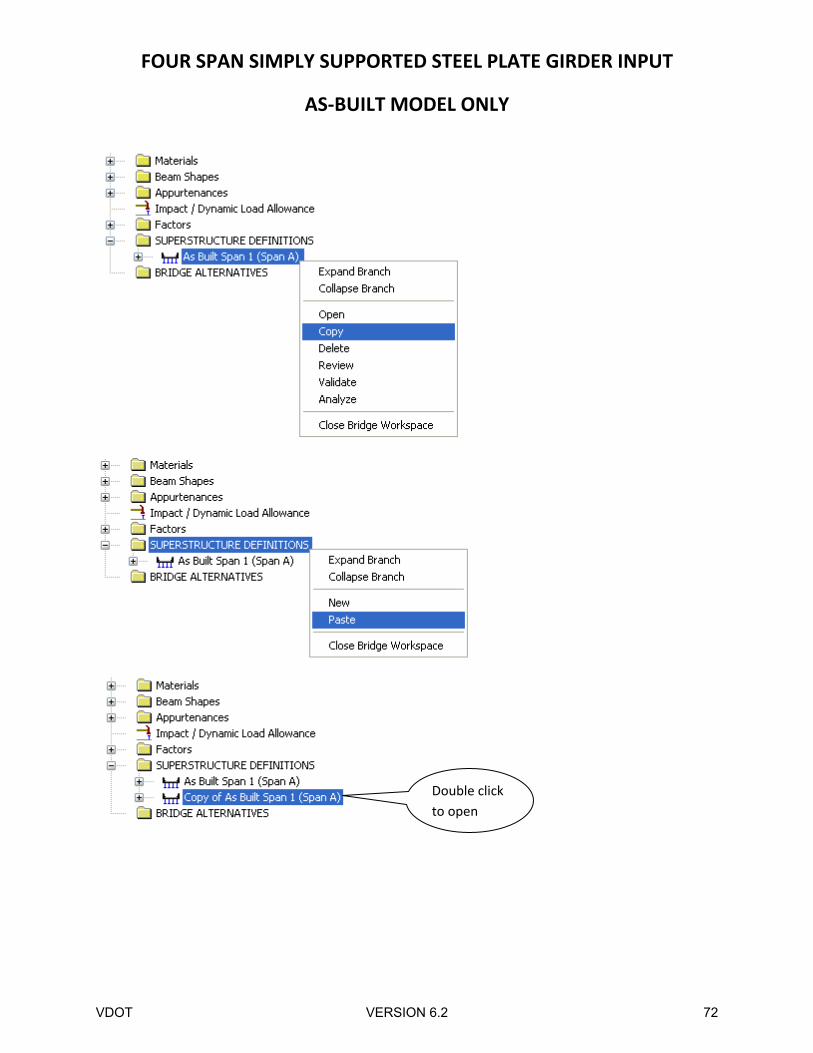
7. Creating Additional Spans
Once the first span is created, it can be copied for the other spans. Simply right click on As Built Span 1
and select copy and then right click on superstructure definitions and hit paste as shown below.
Click to accept
and close
VDOT VERSION 6.2 71
FOUR SPAN SIMPLY SUPPORTED STEEL PLATE GIRDER INPUT
AS‐BUILT MODEL ONLY
Double click
to open
VDOT VERSION 6.2 72
FOUR SPAN SIMPLY SUPPORTED STEEL PLATE GIRDER INPUT
AS‐BUILT MODEL ONLY
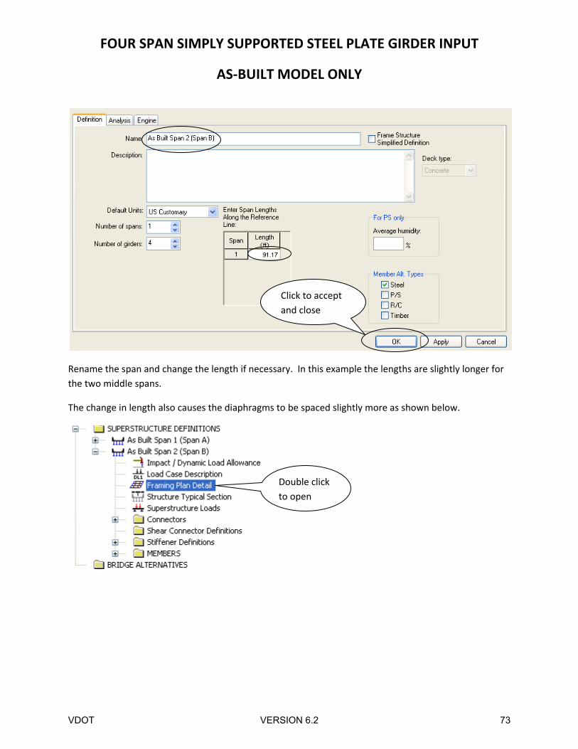
Rename the span and change the length if necessary. In this example the lengths are slightly longer for
the two middle spans.
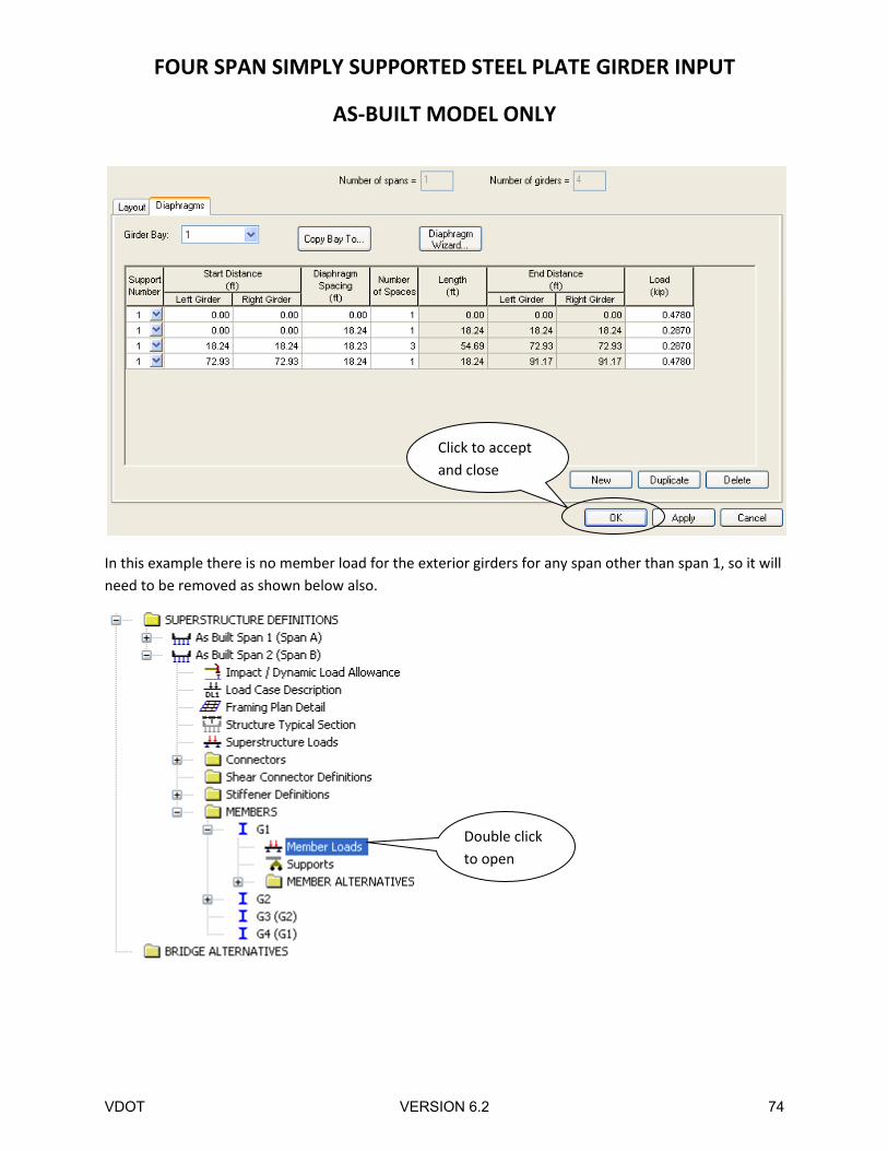
The change in length also causes the diaphragms to be spaced slightly more as shown below.
Click to accept
and close
Double click
to open
VDOT VERSION 6.2 73
FOUR SPAN SIMPLY SUPPORTED STEEL PLATE GIRDER INPUT
AS‐BUILT MODEL ONLY
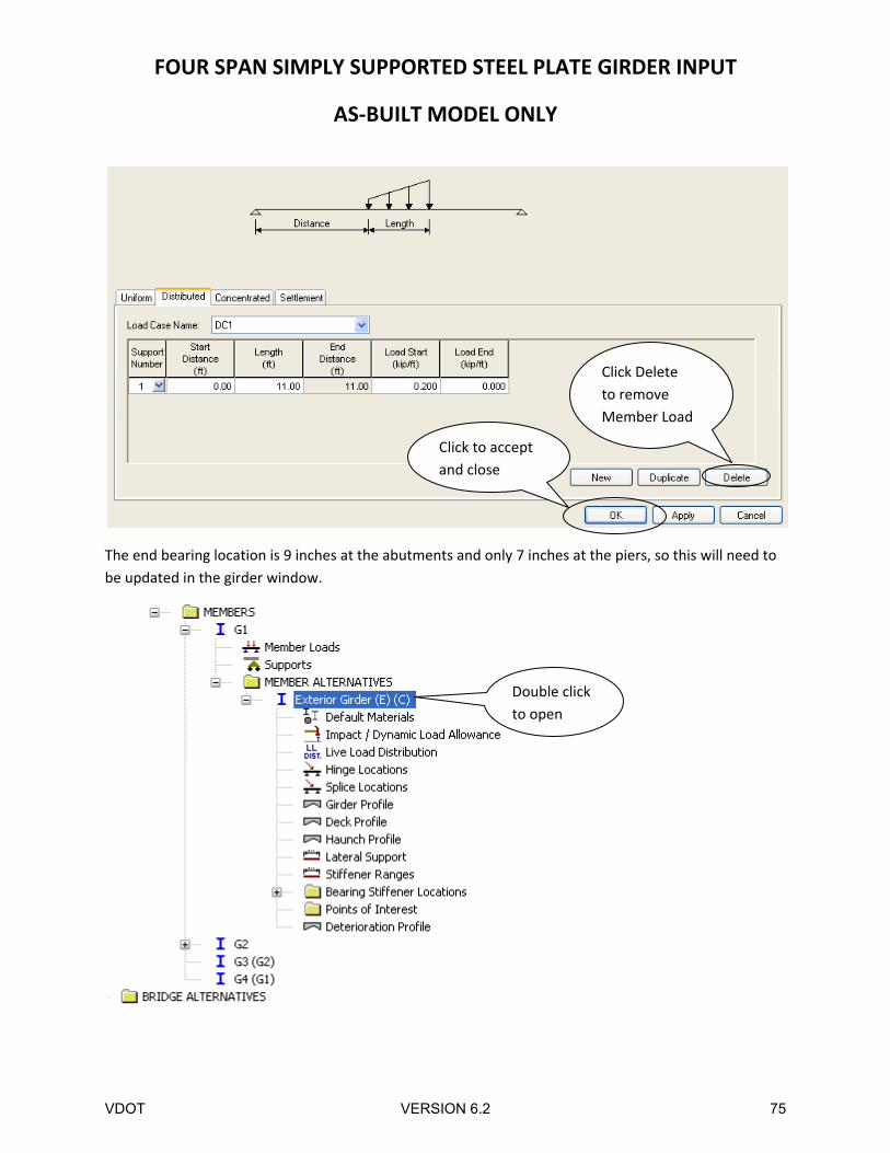
In this example there is no member load for the exterior girders for any span other than span 1, so it will
need to be removed as shown below also.
Double click
to open
Click to accept
and close
VDOT VERSION 6.2 74
FOUR SPAN SIMPLY SUPPORTED STEEL PLATE GIRDER INPUT
AS‐BUILT MODEL ONLY
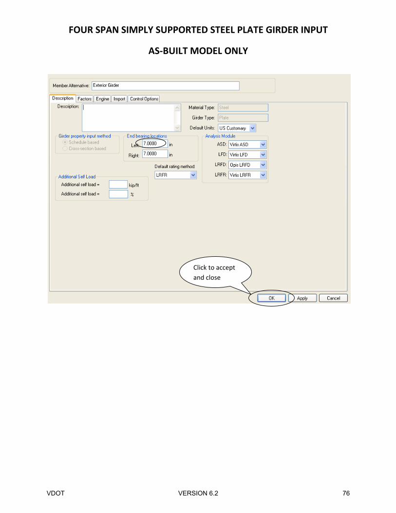
The end bearing location is 9 inches at the abutments and only 7 inches at the piers, so this will need to
be updated in the girder window.
Click to accept
and close
Double click
to open
Click Delete
to remove
Member Load
VDOT VERSION 6.2 75
FOUR SPAN SIMPLY SUPPORTED STEEL PLATE GIRDER INPUT
AS‐BUILT MODEL ONLY
Click to accept
and close
VDOT VERSION 6.2 76
FOUR SPAN SIMPLY SUPPORTED STEEL PLATE GIRDER INPUT
AS‐BUILT MODEL ONLY
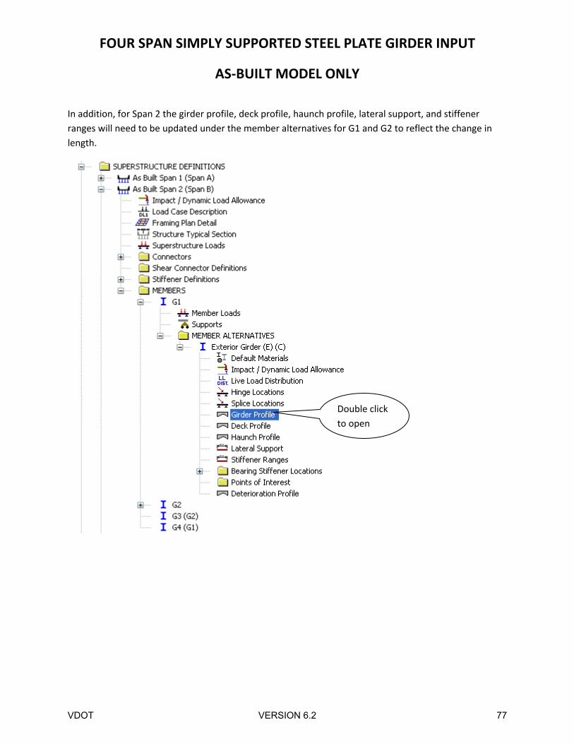
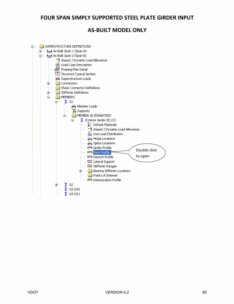
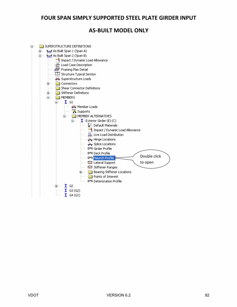
In addition, for Span 2 the girder profile, deck profile, haunch profile, lateral support, and stiffener
ranges will need to be updated under the member alternatives for G1 and G2 to reflect the change in
length.
Double click
to open
VDOT VERSION 6.2 77
FOUR SPAN SIMPLY SUPPORTED STEEL PLATE GIRDER INPUT
AS‐BUILT MODEL ONLY
VDOT VERSION 6.2 78
FOUR SPAN SIMPLY SUPPORTED STEEL PLATE GIRDER INPUT
AS‐BUILT MODEL ONLY
Click to accept
and close
VDOT VERSION 6.2 79
FOUR SPAN SIMPLY SUPPORTED STEEL PLATE GIRDER INPUT
AS‐BUILT MODEL ONLY
Double click
to open
VDOT VERSION 6.2 80
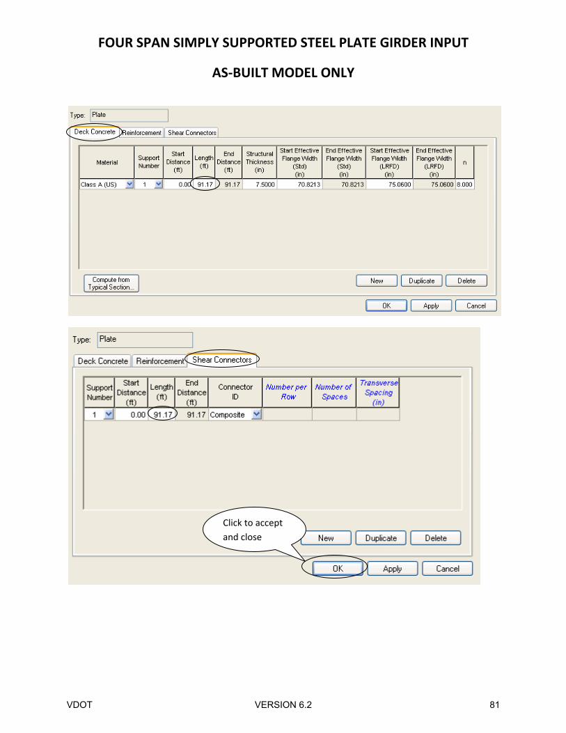
FOUR SPAN SIMPLY SUPPORTED STEEL PLATE GIRDER INPUT
AS‐BUILT MODEL ONLY
Click to accept
and close
VDOT VERSION 6.2 81
FOUR SPAN SIMPLY SUPPORTED STEEL PLATE GIRDER INPUT
AS‐BUILT MODEL ONLY
Double click
to open
VDOT VERSION 6.2 82
FOUR SPAN SIMPLY SUPPORTED STEEL PLATE GIRDER INPUT
AS‐BUILT MODEL ONLY
Click to accept
and close
VDOT VERSION 6.2 83

FOUR SPAN SIMPLY SUPPORTED STEEL PLATE GIRDER INPUT
AS‐BUILT MODEL ONLY
Double click
to open
VDOT VERSION 6.2 84
FOUR SPAN SIMPLY SUPPORTED STEEL PLATE GIRDER INPUT
AS‐BUILT MODEL ONLY
Click to accept
and close
VDOT VERSION 6.2 85

FOUR SPAN SIMPLY SUPPORTED STEEL PLATE GIRDER INPUT
AS‐BUILT MODEL ONLY
Double click
to open
VDOT VERSION 6.2 86
FOUR SPAN SIMPLY SUPPORTED STEEL PLATE GIRDER INPUT
AS‐BUILT MODEL ONLY
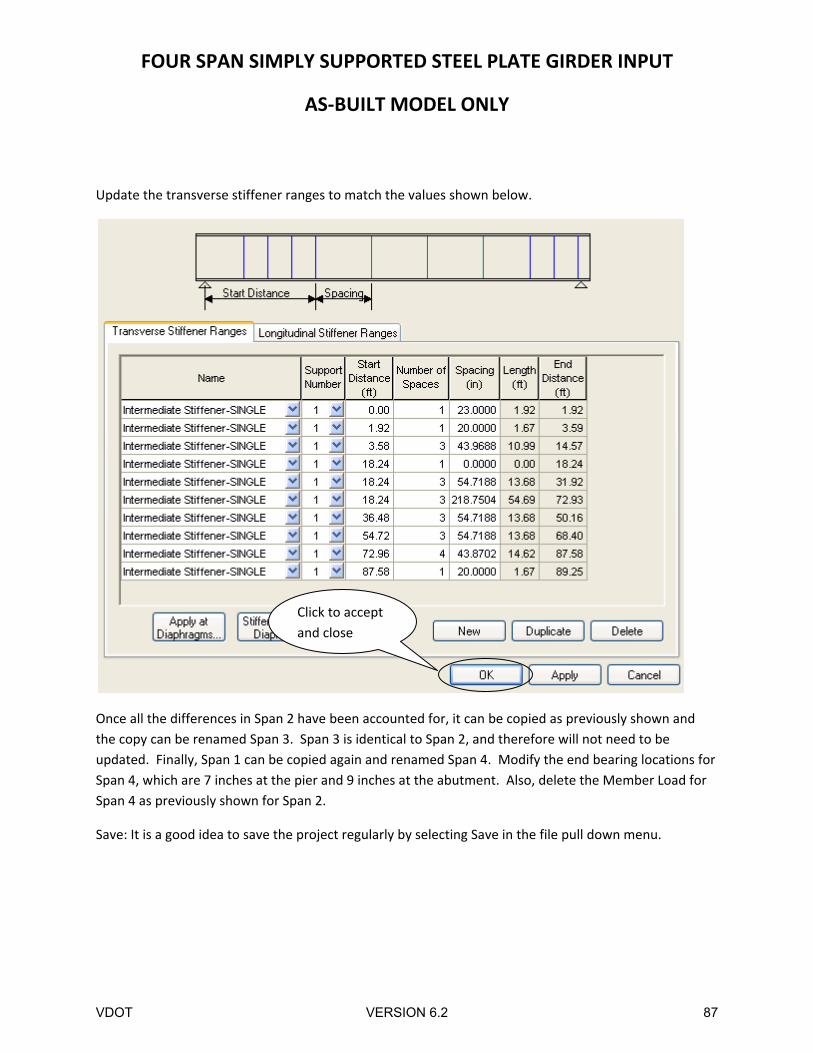
Update the transverse stiffener ranges to match the values shown below.
Once all the differences in Span 2 have been accounted for, it can be copied as previously shown and
the copy can be renamed Span 3. Span 3 is identical to Span 2, and therefore will not need to be
updated. Finally, Span 1 can be copied again and renamed Span 4. Modify the end bearing locations for
Span 4, which are 7 inches at the pier and 9 inches at the abutment. Also, delete the Member Load for
Span 4 as previously shown for Span 2.
Save: It is a good idea to save the project regularly by selecting Save in the file pull down menu.
Click to accept
and close
VDOT VERSION 6.2 87
FOUR SPAN SIMPLY SUPPORTED STEEL PLATE GIRDER INPUT
AS‐BUILT MODEL ONLY
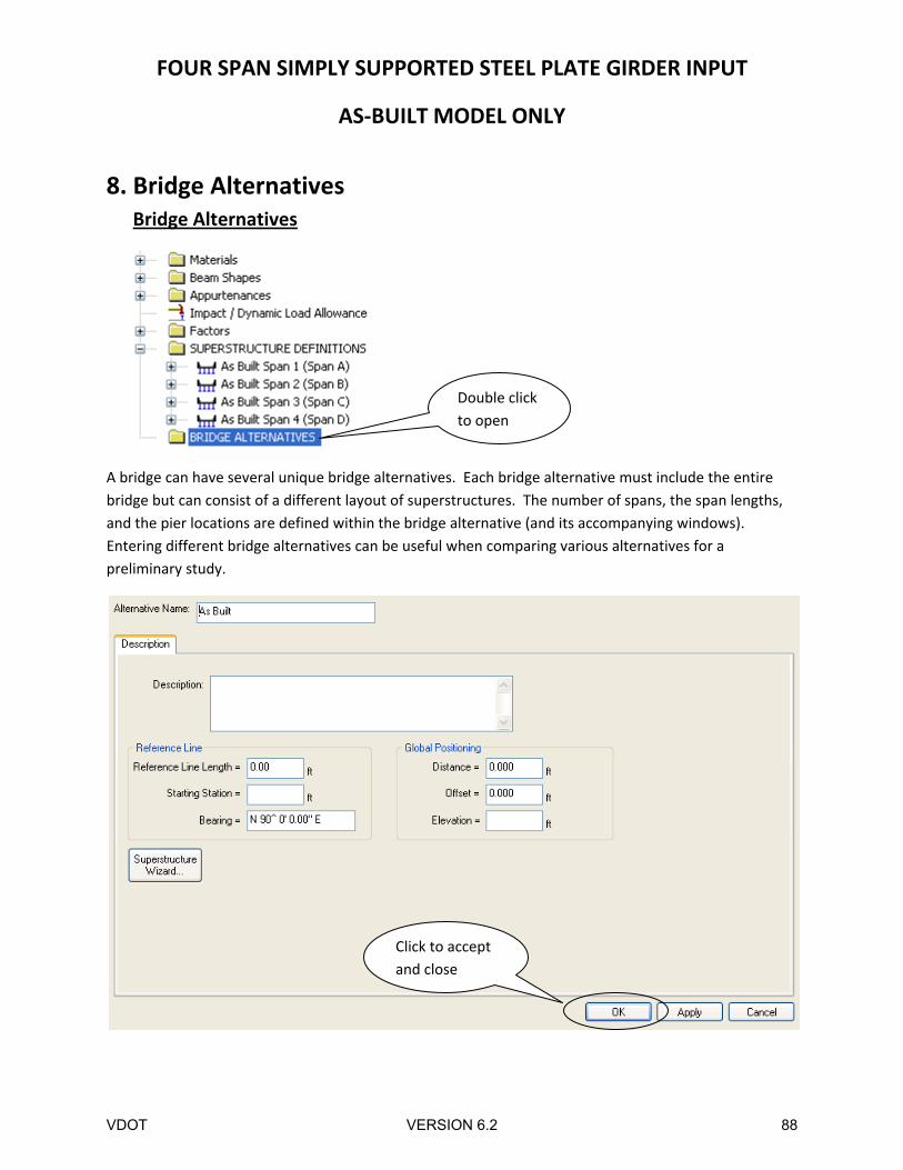
8. Bridge Alternatives Bridge Alternatives
A bridge can have several unique bridge alternatives. Each bridge alternative must include the entire
bridge but can consist of a different layout of superstructures. The number of spans, the span lengths,
and the pier locations are defined within the bridge alternative (and its accompanying windows).
Entering different bridge alternatives can be useful when comparing various alternatives for a
preliminary study.
Double click
to open
Click to accept
and close
VDOT VERSION 6.2 88
FOUR SPAN SIMPLY SUPPORTED STEEL PLATE GIRDER INPUT
AS‐BUILT MODEL ONLY
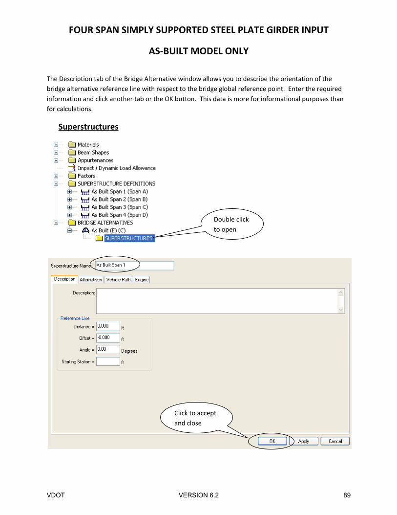
The Description tab of the Bridge Alternative window allows you to describe the orientation of the
bridge alternative reference line with respect to the bridge global reference point. Enter the required
information and click another tab or the OK button. This data is more for informational purposes than
for calculations.
Superstructures
Double click
to open
Click to accept
and close
VDOT VERSION 6.2 89
FOUR SPAN SIMPLY SUPPORTED STEEL PLATE GIRDER INPUT
AS‐BUILT MODEL ONLY
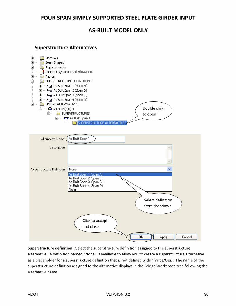
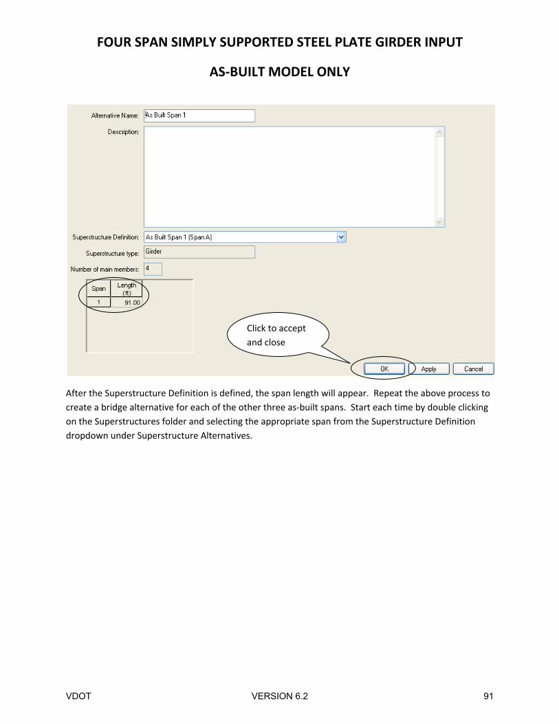
Superstructure Alternatives
Superstructure definition: Select the superstructure definition assigned to the superstructure
alternative. A definition named “None” is available to allow you to create a superstructure alternative
as a placeholder for a superstructure definition that is not defined within Virtis/Opis. The name of the
superstructure definition assigned to the alternative displays in the Bridge Workspace tree following the
alternative name.
Double click
to open
Select definition
from dropdown
Click to accept
and close
VDOT VERSION 6.2 90
FOUR SPAN SIMPLY SUPPORTED STEEL PLATE GIRDER INPUT
AS‐BUILT MODEL ONLY
After the Superstructure Definition is defined, the span length will appear. Repeat the above process to
create a bridge alternative for each of the other three as‐built spans. Start each time by double clicking
on the Superstructures folder and selecting the appropriate span from the Superstructure Definition
dropdown under Superstructure Alternatives.
Click to accept
and close
VDOT VERSION 6.2 91
FOUR SPAN SIMPLY SUPPORTED STEEL PLATE GIRDER INPUT
AS‐BUILT MODEL ONLY
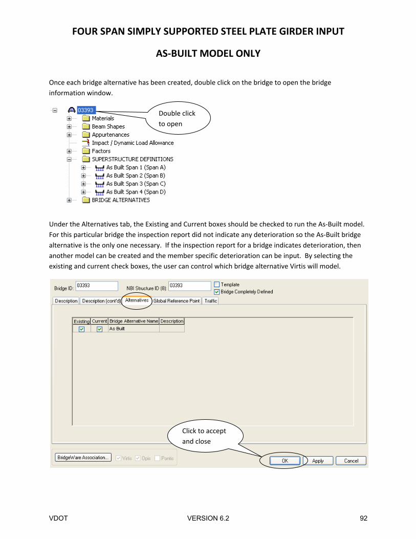
Once each bridge alternative has been created, double click on the bridge to open the bridge
information window.
Under the Alternatives tab, the Existing and Current boxes should be checked to run the As‐Built model.
For this particular bridge the inspection report did not indicate any deterioration so the As‐Built bridge
alternative is the only one necessary. If the inspection report for a bridge indicates deterioration, then
another model can be created and the member specific deterioration can be input. By selecting the
existing and current check boxes, the user can control which bridge alternative Virtis will model.
Double click
to open
Click to accept
and close
VDOT VERSION 6.2 92
FOUR SPAN SIMPLY SUPPORTED STEEL PLATE GIRDER INPUT
AS‐BUILT MODEL ONLY
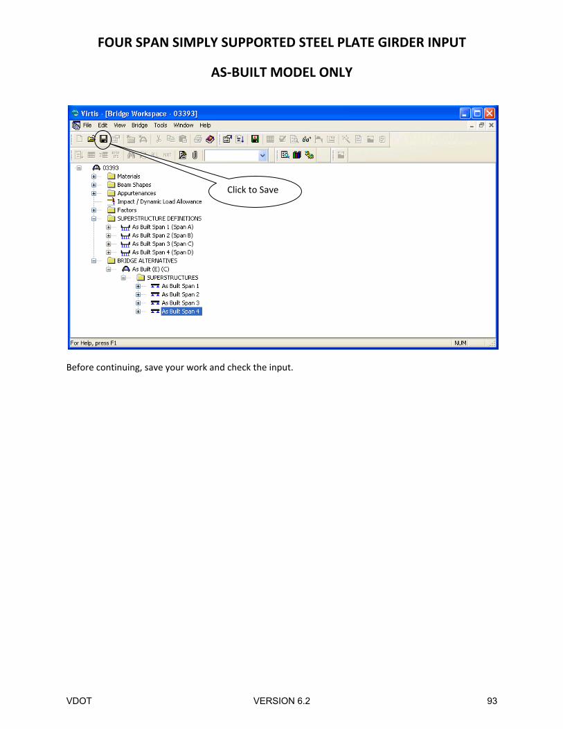
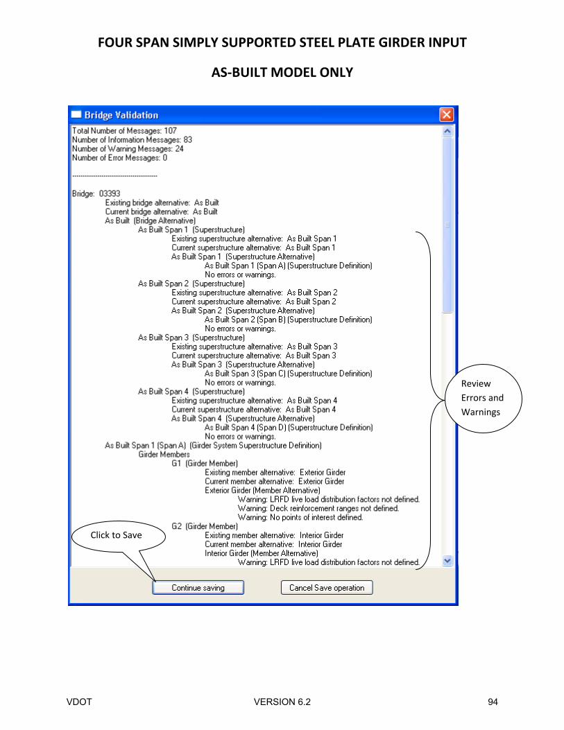
Before continuing, save your work and check the input.
Click to Save
VDOT VERSION 6.2 93
FOUR SPAN SIMPLY SUPPORTED STEEL PLATE GIRDER INPUT
AS‐BUILT MODEL ONLY
Click to Save
Review
Errors and
Warnings
VDOT VERSION 6.2 94
FOUR SPAN SIMPLY SUPPORTED STEEL PLATE GIRDER INPUT
AS‐BUILT MODEL ONLY
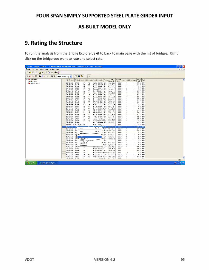
9. Rating the Structure
To run the analysis from the Bridge Explorer, exit to back to main page with the list of bridges. Right
click on the bridge you want to rate and select rate.
VDOT VERSION 6.2 95
FOUR SPAN SIMPLY SUPPORTED STEEL PLATE GIRDER INPUT
AS‐BUILT MODEL ONLY
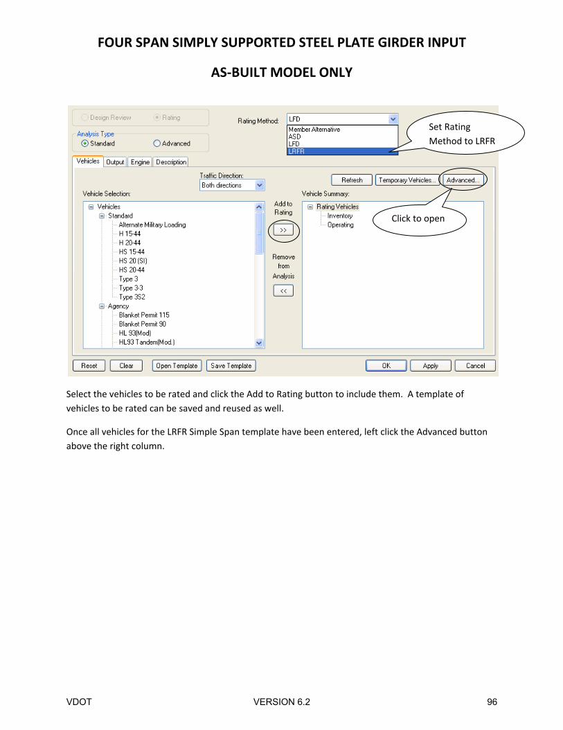
Select the vehicles to be rated and click the Add to Rating button to include them. A template of
vehicles to be rated can be saved and reused as well.
Once all vehicles for the LRFR Simple Span template have been entered, left click the Advanced button
above the right column.
Set Rating
Method to LRFR
Click to open
VDOT VERSION 6.2 96
FOUR SPAN SIMPLY SUPPORTED STEEL PLATE GIRDER INPUT
AS‐BUILT MODEL ONLY
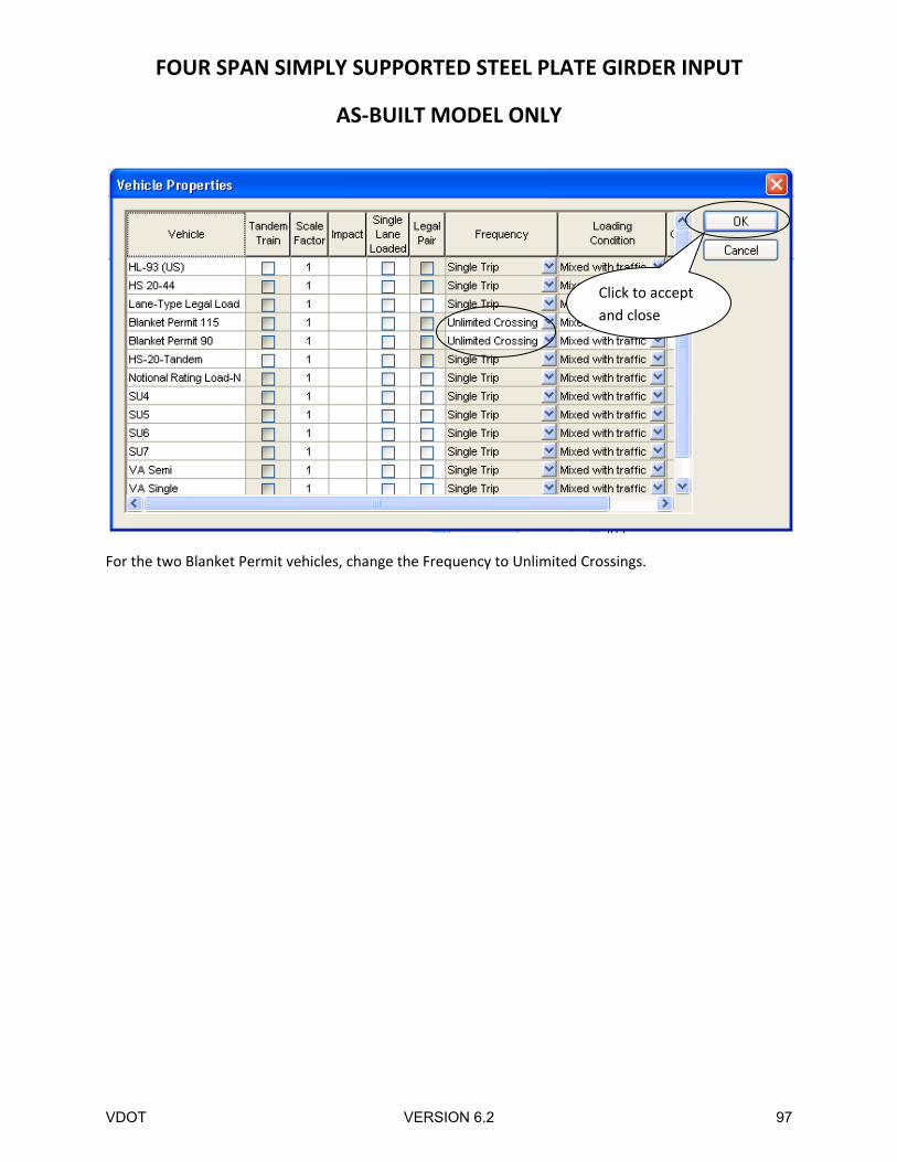
For the two Blanket Permit vehicles, change the Frequency to Unlimited Crossings.
Click to accept
and close
VDOT VERSION 6.2 97
FOUR SPAN SIMPLY SUPPORTED STEEL PLATE GIRDER INPUT
AS‐BUILT MODEL ONLY
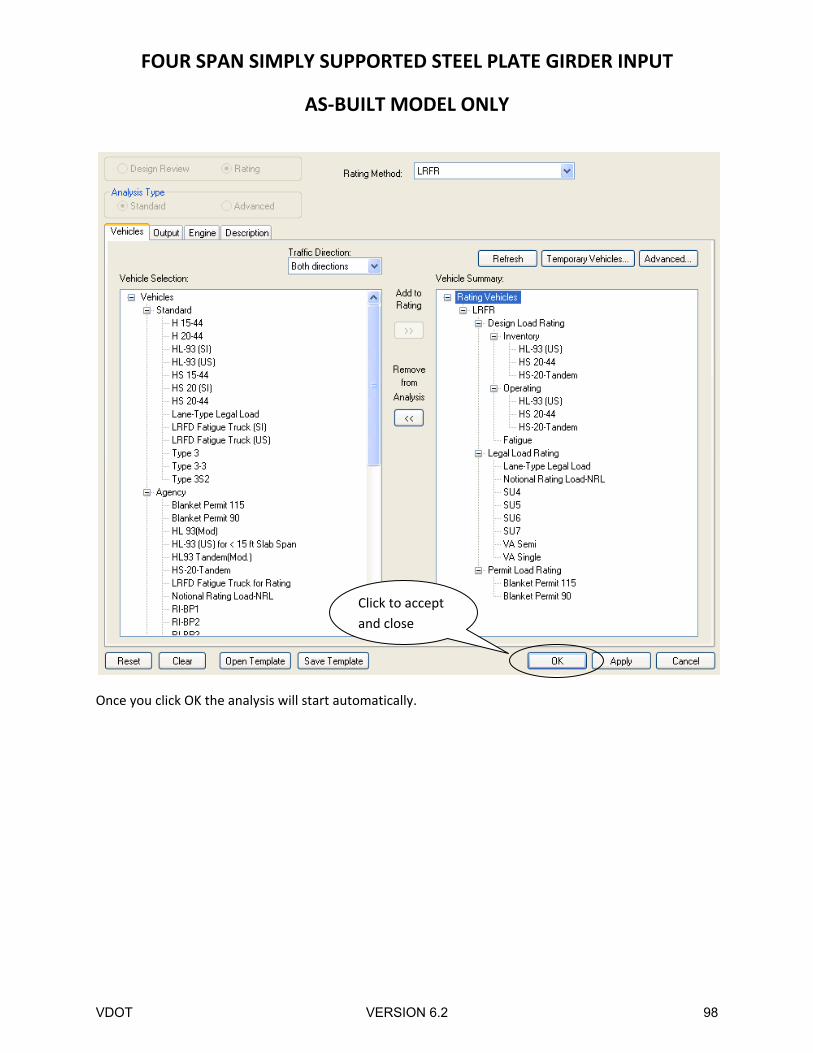
Once you click OK the analysis will start automatically.
Click to accept
and close
VDOT VERSION 6.2 98
FOUR SPAN SIMPLY SUPPORTED STEEL PLATE GIRDER INPUT
AS‐BUILT MODEL ONLY
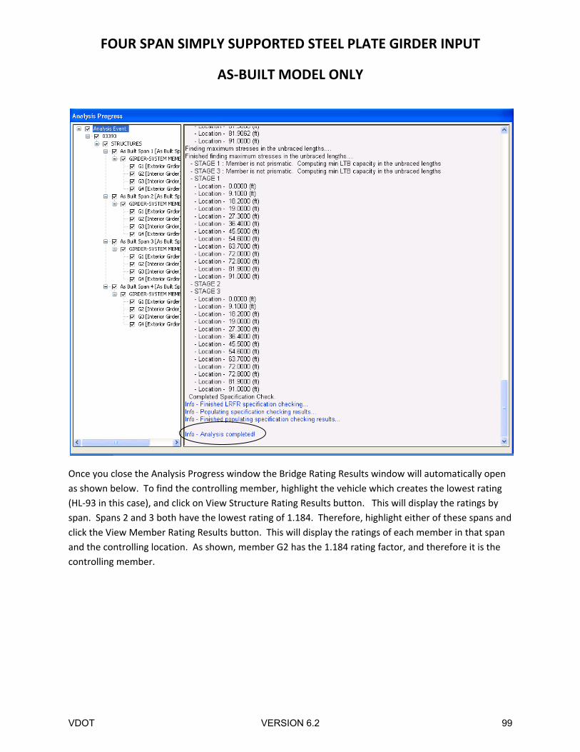
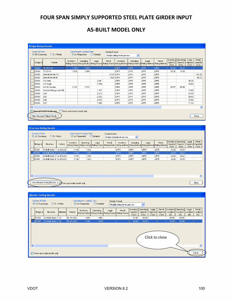
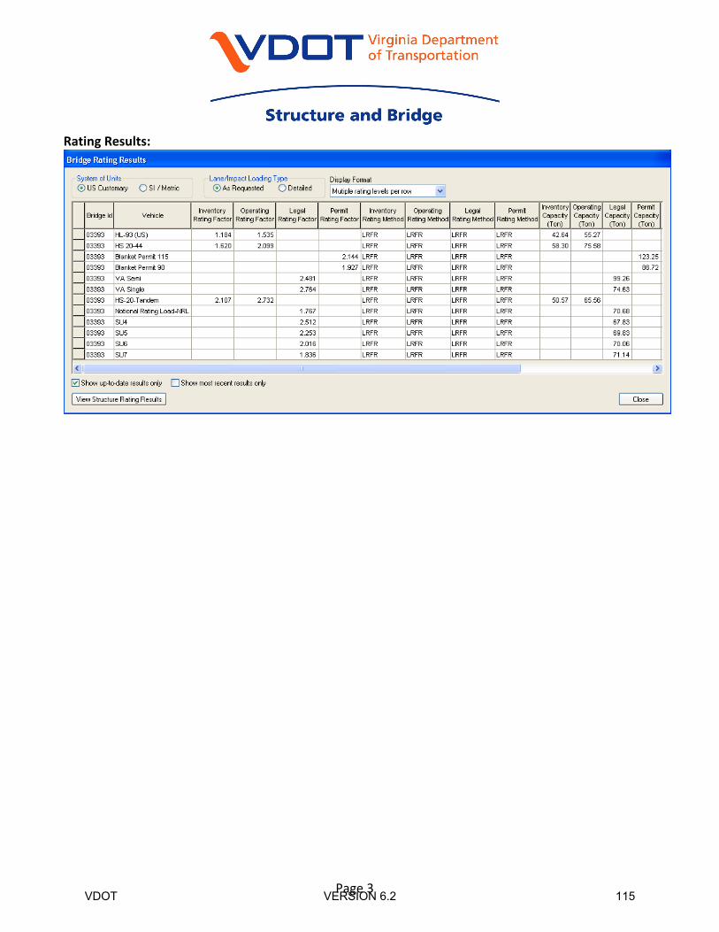
Once you close the Analysis Progress window the Bridge Rating Results window will automatically open
as shown below. To find the controlling member, highlight the vehicle which creates the lowest rating
(HL‐93 in this case), and click on View Structure Rating Results button. This will display the ratings by
span. Spans 2 and 3 both have the lowest rating of 1.184. Therefore, highlight either of these spans and
click the View Member Rating Results button. This will display the ratings of each member in that span
and the controlling location. As shown, member G2 has the 1.184 rating factor, and therefore it is the
controlling member.
VDOT VERSION 6.2 99
FOUR SPAN SIMPLY SUPPORTED STEEL PLATE GIRDER INPUT
AS‐BUILT MODEL ONLY
Click to close
VDOT VERSION 6.2 100
FOUR SPAN SIMPLY SUPPORTED STEEL PLATE GIRDER INPUT
AS‐BUILT MODEL ONLY
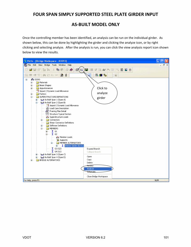
Once the controlling member has been identified, an analysis can be run on the individual girder. As
shown below, this can be done by highlighting the girder and clicking the analyze icon, or by right
clicking and selecting analyze. After the analysis is run, you can click the view analysis report icon shown
below to view the results.
Click to
analyze
girder
VDOT VERSION 6.2 101
FOUR SPAN SIMPLY SUPPORTED STEEL PLATE GIRDER INPUT
AS‐BUILT MODEL ONLY
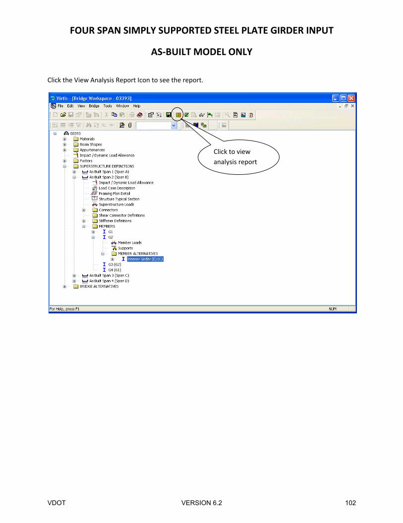
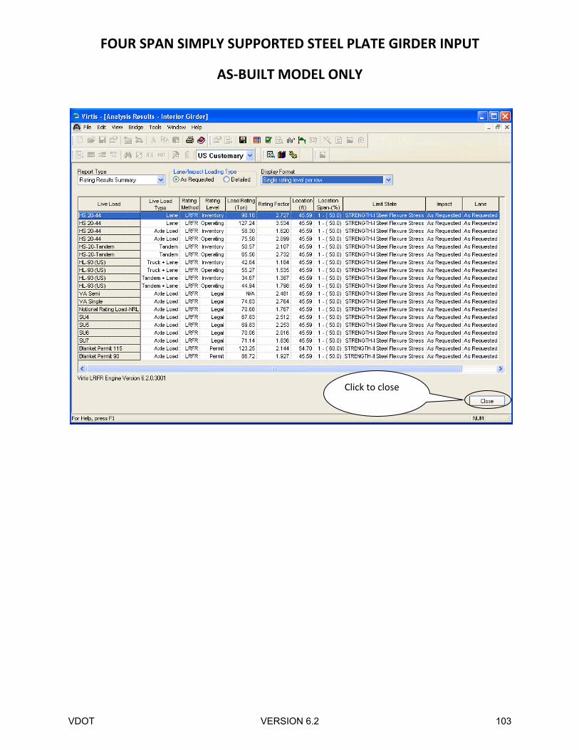
Click the View Analysis Report Icon to see the report.
Click to view
analysis report
VDOT VERSION 6.2 102
FOUR SPAN SIMPLY SUPPORTED STEEL PLATE GIRDER INPUT
AS‐BUILT MODEL ONLY
Click to close
VDOT VERSION 6.2 103
FOUR SPAN SIMPLY SUPPORTED STEEL PLATE GIRDER INPUT
AS‐BUILT MODEL ONLY
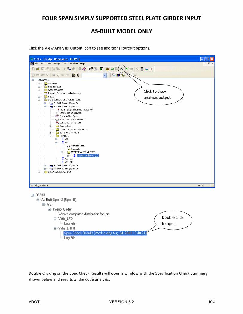
Click the View Analysis Output Icon to see additional output options.
Double Clicking on the Spec Check Results will open a window with the Specification Check Summary
shown below and results of the code analysis.
Click to view
analysis output
Double click
to open
VDOT VERSION 6.2 104
FOUR SPAN SIMPLY SUPPORTED STEEL PLATE GIRDER INPUT
AS‐BUILT MODEL ONLY
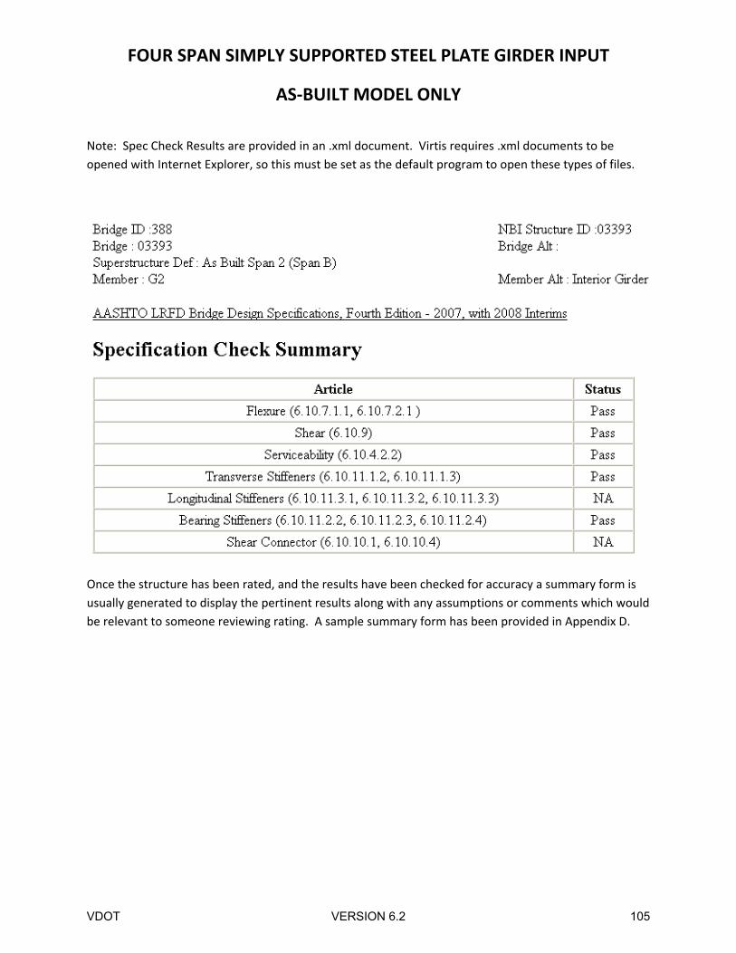
Note: Spec Check Results are provided in an .xml document. Virtis requires .xml documents to be
opened with Internet Explorer, so this must be set as the default program to open these types of files.
Once the structure has been rated, and the results have been checked for accuracy a summary form is
usually generated to display the pertinent results along with any assumptions or comments which would
be relevant to someone reviewing rating. A sample summary form has been provided in Appendix D.
VDOT VERSION 6.2 105
VDOT VERSION 6.2 106
VDOT VERSION 6.2 107
VDOT VERSION 6.2 108
VDOT VERSION 6.2 109
VDOT VERSION 6.2 110
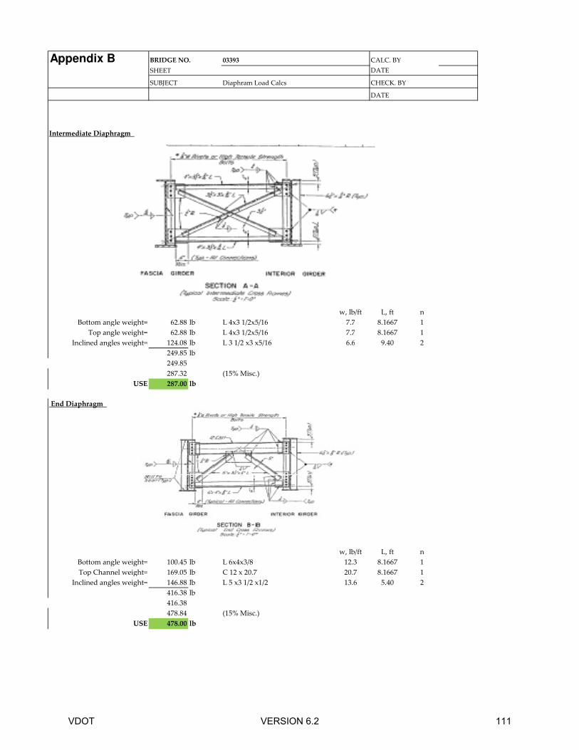
Appendix B BRIDGE NO. 03393
SHEET DATE
SUBJECT Diaphram Load Calcs
DATE
Intermediate Diaphragm
w, lb/ft L, ft n
Bottom angle weight= 62.88 lb L 4x3 1/2x5/16 7.7 8.1667 1
Top angle weight= 62.88 lb L 4x3 1/2x5/16 7.7 8.1667 1
Inclined angles weight= 124.08 lb L 3 1/2 x3 x5/16 6.6 9.40 2
249.85 lb
249.85
287.32 (15% Misc.)
USE 287.00 lb
End Diaphragm
CALC. BY
CHECK. BY
End Diaphragm
w, lb/ft L, ft n
Bottom angle weight= 100.45 lb L 6x4x3/8 12.3 8.1667 1
Top Channel weight= 169.05 lb C 12 x 20.7 20.7 8.1667 1
Inclined angles weight= 146.88 lb L 5 x3 1/2 x1/2 13.6 5.40 2
416.38 lb
416.38
478.84 (15% Misc.)
USE 478.00 lb
VDOT VERSION 6.2 111
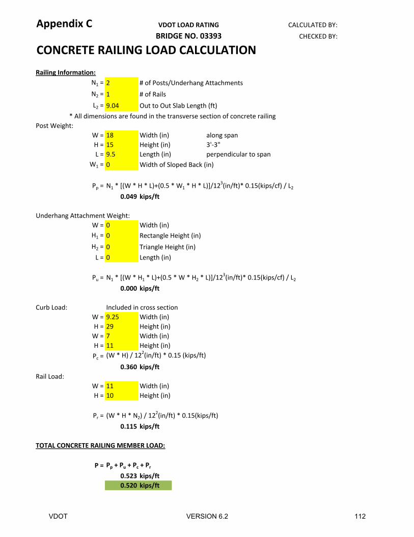
Appendix C VDOT LOAD RATING CALCULATED BY:
BRIDGE NO. 03393 CHECKED BY:
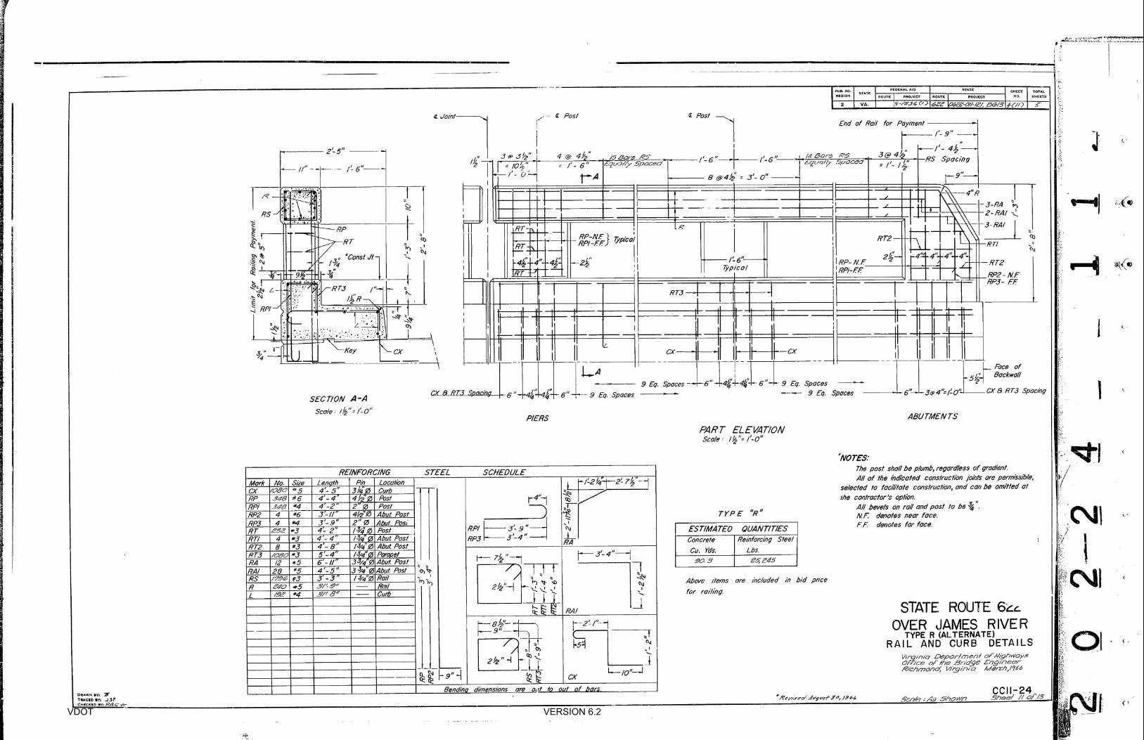
CONCRETE RAILING LOAD CALCULATION
Railing Information:
N1 = 2 # of Posts/Underhang Attachments
N2 = 1 # of Rails
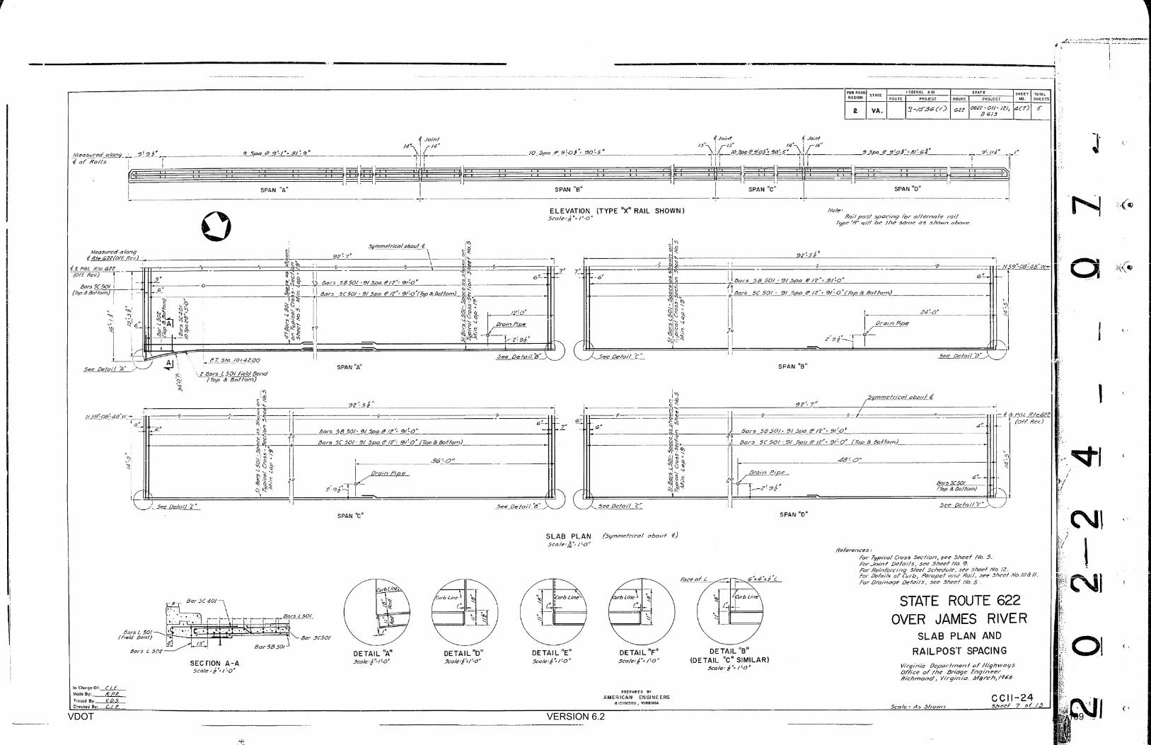
L2 = 9.04 Out to Out Slab Length (ft)
* All dimensions are found in the transverse section of concrete railing
Post Weight:
W = 18 Width (in) along span
H = 15 Height (in) 3'-3"
L = 9.5 Length (in) perpendicular to span
W1 = 0 Width of Sloped Back (in)
Pp = N1 * [(W * H * L)+(0.5 * W1 * H * L)]/123(in/ft)* 0.15(kips/cf) / L2
0.049 kips/ft
Underhang Attachment Weight:
W = 0 Width (in)
H1 = 0 Rectangle Height (in)
H2 = 0 Triangle Height (in)
L = 0 Length (in)
Pu = N1 * [(W * H1 * L)+(0.5 * W * H2 * L)]/123(in/ft)* 0.15(kips/cf) / L2
0.000 kips/ft
Curb Load: Included in cross section
W = 9.25 Width (in)
H = 29 Height (in)
W = 7 Width (in)
H = 11 Height (in)
Pc = (W * H) / 122(in/ft) * 0.15 (kips/ft)
0.360 kips/ft
Rail Load:
W = 11 Width (in)
H = 10 Height (in)
Pr = (W * H * N2) / 122(in/ft) * 0.15(kips/ft)
0.115 kips/ft
TOTAL CONCRETE RAILING MEMBER LOAD:
P = Pp + Pu + Pc + Pr
0.523 kips/ft
0.520 kips/ft
VDOT VERSION 6.2 112
Page 1
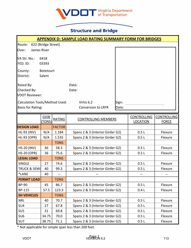
APPENDIX D: SAMPLE LOAD RATING SUMMARY FORM FOR BRIDGES
Route: 622 (Bridge Street)
Over: James River
VA Str. No.: 6418
Sign:
FED. ID: 03393
County: Botetourt
District: Salem
Rated By: Date:
Checked By: Date:
VDOT Reviewer:
Calculation Tools/Method Used: Virtis 6.2
Basis for Rating: Conversion to LRFR Date:
GVW
(TONS) RATING CONTROLLING MEMBERS
CONTROLLING
LOCATION
CONTROLLING
FORCE
DESIGN LOAD FACTOR
HL-93 (INV) N/A 1.184 Spans 2 & 3 (Interior Girder G2) 0.5 L Flexure
HL-93 (OPR) N/A 1.535 Spans 2 & 3 (Interior Girder G2) 0.5 L Flexure
TONS
HS-20 (INV) 36 58.3 Spans 2 & 3 (Interior Girder G2) 0.5 L Flexure
HS-20 (OPR) 36 75.6 Spans 2 & 3 (Interior Girder G2) 0.5 L Flexure
LEGAL LOAD TONS
SINGLE 27 74.6 Spans 2 & 3 (Interior Girder G2) 0.5 L Flexure
TRUCK & SEMI 40 99.3 Spans 2 & 3 (Interior Girder G2) 0.5 L Flexure
*LANE 40 -- -- -- --
PERMIT LOAD TONS
BP-90 45 86.7 Spans 2 & 3 (Interior Girder G2) 0.5 L Flexure
BP-115 57.5 123.3 Spans 2 & 3 (Interior Girder G2) 0.4 L Flexure
SH VEHICLES TONS
NRL 40 70.7 Spans 2 & 3 (Interior Girder G2) 0.5 L Flexure
SU4 27 67.8 Spans 2 & 3 (Interior Girder G2) 0.5 L Flexure
SU5 31 69.8 Spans 2 & 3 (Interior Girder G2) 0.5 L Flexure
SU6 34.75 70.0 Spans 2 & 3 (Interior Girder G2) 0.5 L Flexure
SU7 38.75 71.1 Spans 2 & 3 (Interior Girder G2) 0.5 L Flexure
* Not applicable for simple span less than 200 feet.
VDOT VERSION 6.2 113
Page 2
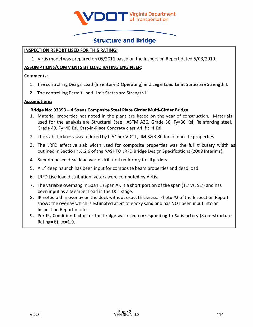
INSPECTION REPORT USED FOR THIS RATING:
1. Virtis model was prepared on 05/2011 based on the Inspection Report dated 6/03/2010.
ASSUMPTIONS/COMMENTS BY LOAD RATING ENGINEER:
Comments:
1. The controlling Design Load (Inventory & Operating) and Legal Load Limit States are Strength I.
2. The controlling Permit Load Limit States are Strength II.
Assumptions:
Bridge No: 03393 – 4 Spans Composite Steel Plate Girder Multi-Girder Bridge.
1. Material properties not noted in the plans are based on the year of construction. Materials
used for the analysis are Structural Steel, ASTM A36, Grade 36, Fy=36 Ksi; Reinforcing steel,
Grade 40, Fy=40 Ksi, Cast-in-Place Concrete class A4, f’c=4 Ksi.
2. The slab thickness was reduced by 0.5” per VDOT, IIM-S&B-80 for composite properties.
3. The LRFD effective slab width used for composite properties was the full tributary width as
outlined in Section 4.6.2.6 of the AASHTO LRFD Bridge Design Specifications (2008 Interims).
4. Superimposed dead load was distributed uniformly to all girders.
5. A 1” deep haunch has been input for composite beam properties and dead load.
6. LRFD Live load distribution factors were computed by Virtis.
7. The variable overhang in Span 1 (Span A), is a short portion of the span (11’ vs. 91’) and has
been input as a Member Load in the DC1 stage.
8. IR noted a thin overlay on the deck without exact thickness. Photo #2 of the Inspection Report
shows the overlay which is estimated at ¼” of epoxy sand and has NOT been input into an
Inspection Report model.
9. Per IR, Condition factor for the bridge was used corresponding to Satisfactory (Superstructure
Rating= 6); φc=1.0.
VDOT VERSION 6.2 114
Page 3
Rating Results:
VDOT VERSION 6.2 115