Embed Size (px)
Citation preview
A51 : MONESTIER DE CLERMONT VIADUCT
• Dominique Quivy VINCI Construction France• Laurent Bastard-Rosset GTM TP Lyon• Michel Londez Independent expert Mécasol
FOUNDATIONS OF MONESTIER VIADUCT
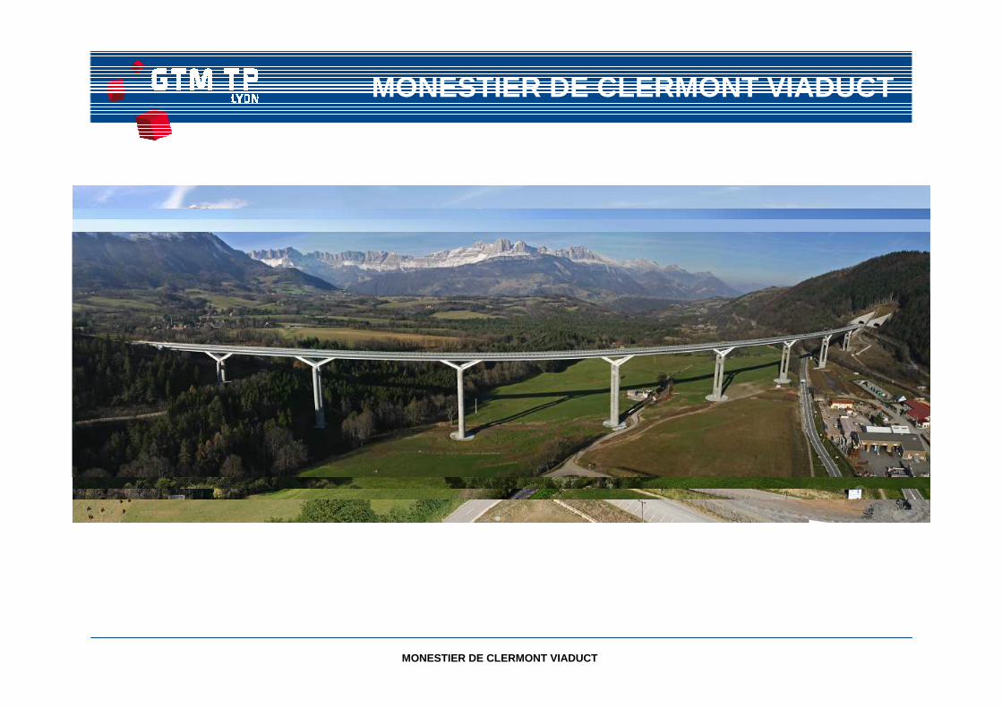
MONESTIER DE CLERMONT VIADUCT
MONESTIER DE CLERMONT VIADUCT
MONESTIER DE CLERMONT VIADUCT
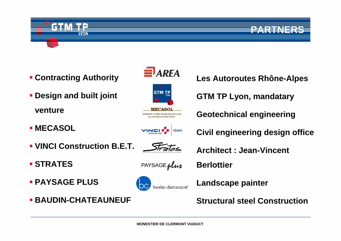
PARTNERS
� Contracting Authority
� Design and built joint
venture
� MECASOL
� VINCI Construction B.E.T.
� STRATES
� PAYSAGE PLUS
� BAUDIN-CHATEAUNEUF
Les Autoroutes Rhône-Alpes
GTM TP Lyon, mandatary
Geotechnical engineering
Civil engineering design office
Architect : Jean-Vincent
Berlottier
Landscape painter
Structural steel Construction
MONESTIER DE CLERMONT VIADUCT
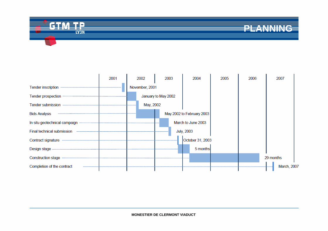
PLANNING
MONESTIER DE CLERMONT VIADUCT
MONESTIER DE CLERMONT VIADUCT
MONESTIER DE CLERMONT VIADUCT
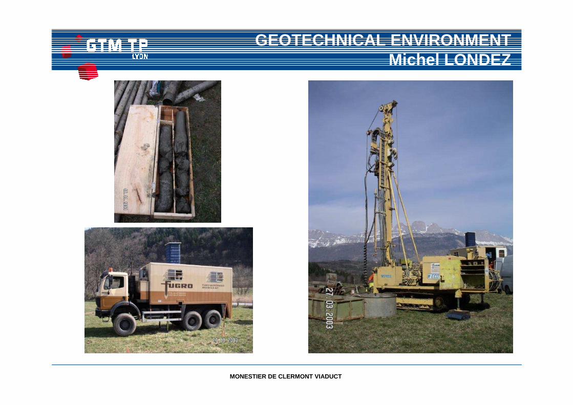
GEOTECHNICAL ENVIRONMENTMichel LONDEZ
MONESTIER DE CLERMONT VIADUCT
Che
min
de fe
r
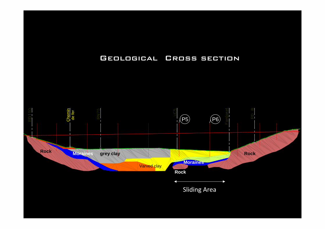
Geological Cross section
grey clay
Clay and blocksvvy
Moraines
Moraines
Sliding Area
P5 P6
Rock Rock
RockVarved clay
MONESTIER DE CLERMONT VIADUCT
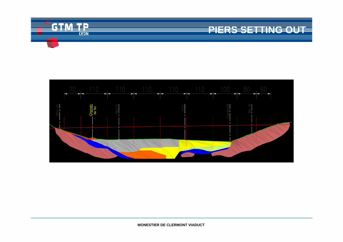
PIERS SETTING OUT
Che
min
de fe
r
MONESTIER DE CLERMONT VIADUCT
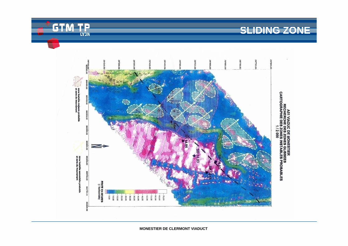
SLIDING ZONE
MONESTIER DE CLERMONT VIADUCT
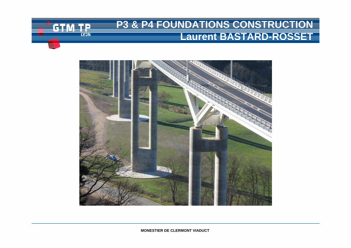
P3 & P4 FOUNDATIONS CONSTRUCTIONLaurent BASTARD -ROSSET
MONESTIER DE CLERMONT VIADUCT
FOUNDATIONS
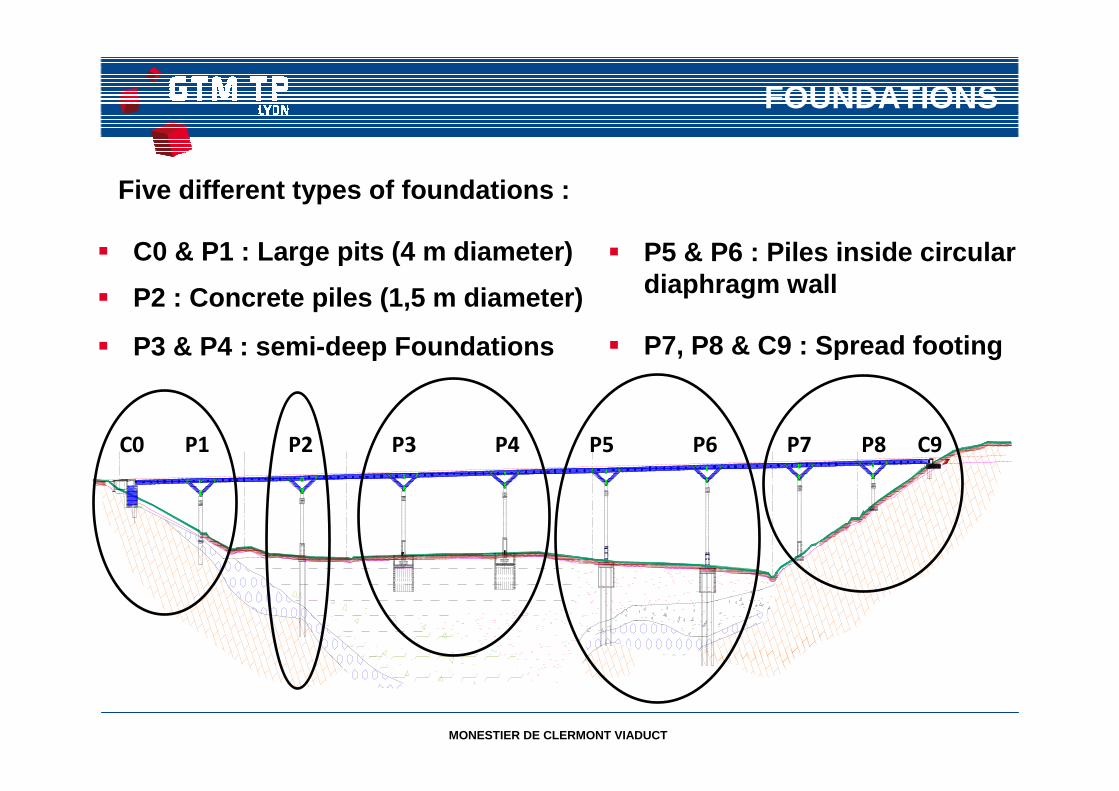
Five different types of foundations :
� C0 & P1 : Large pits (4 m diameter)
� P2 : Concrete piles (1,5 m diameter)
� P3 & P4 : semi-deep Foundations
� P5 & P6 : Piles inside circular diaphragm wall
� P7, P8 & C9 : Spread footing
C0 P1 P2 P3 P4 P5 P6 P7 P8 C9
MONESTIER DE CLERMONT VIADUCT
P3 & P4 FOUNDATIONS
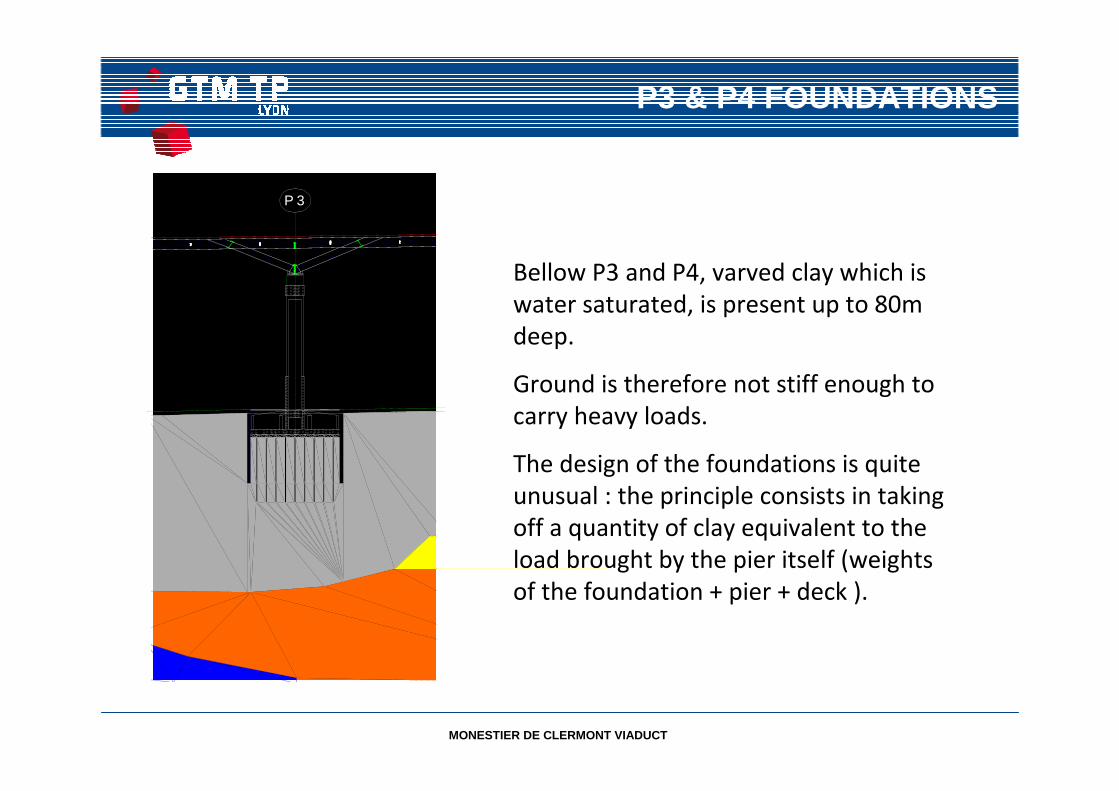
Bellow P3 and P4, varved clay which is
water saturated, is present up to 80m
deep.
Ground is therefore not stiff enough to
carry heavy loads.
The design of the foundations is quite
unusual : the principle consists in taking
off a quantity of clay equivalent to the
load brought by the pier itself (weights
of the foundation + pier + deck ).
P 3
MONESTIER DE CLERMONT VIADUCT
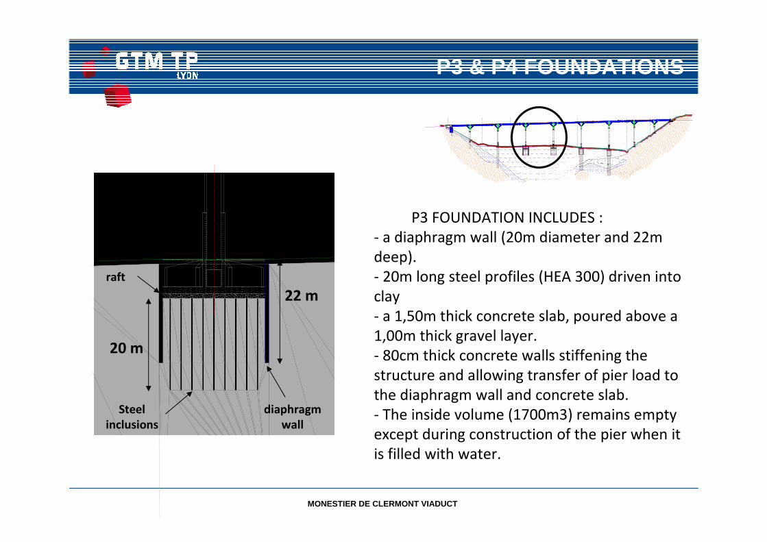
P3 FOUNDATION INCLUDES :
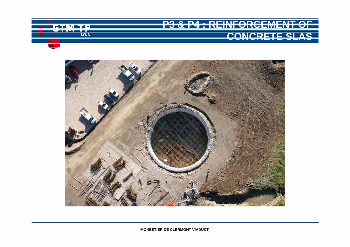
- a diaphragm wall (20m diameter and 22m
deep).
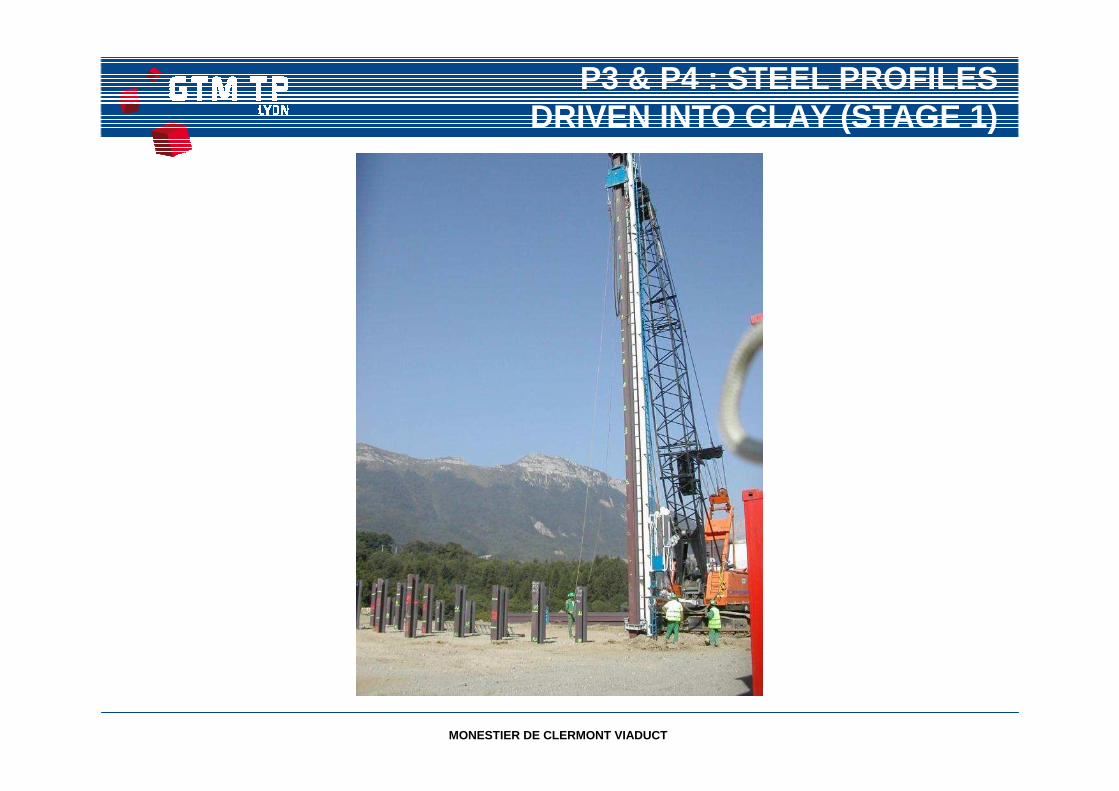
- 20m long steel profiles (HEA 300) driven into
clay
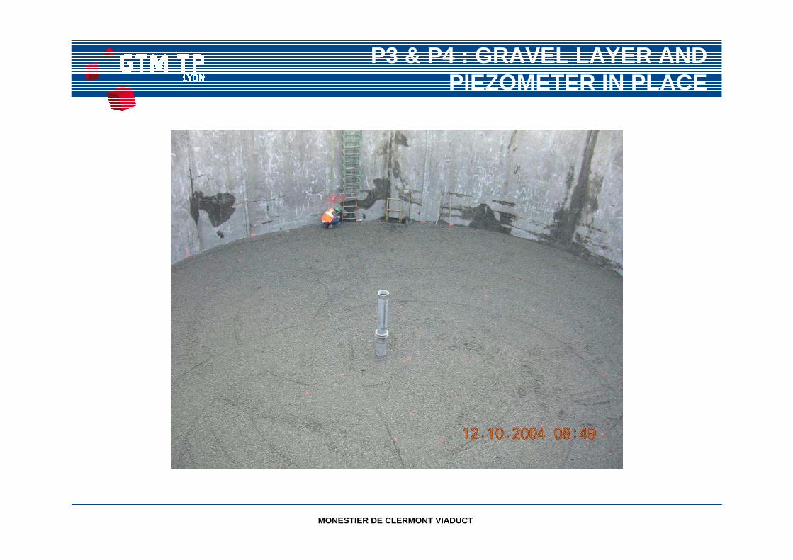
- a 1,50m thick concrete slab, poured above a
1,00m thick gravel layer.
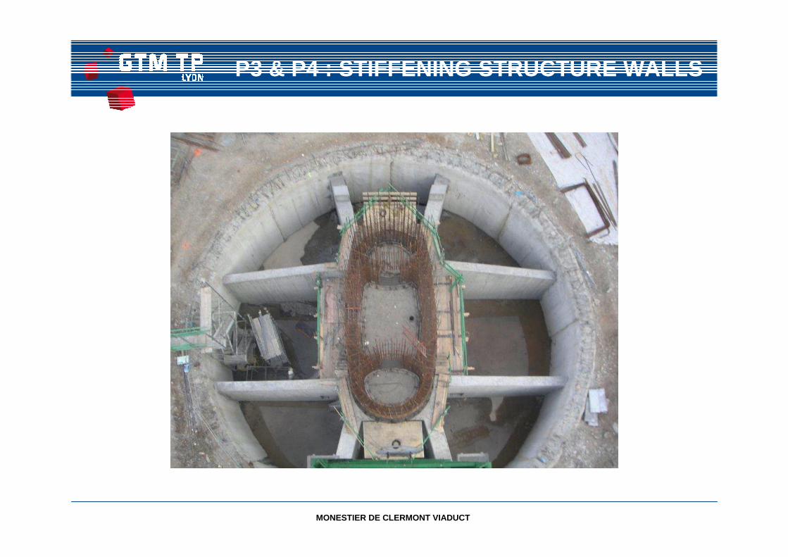
- 80cm thick concrete walls stiffening the
structure and allowing transfer of pier load to
the diaphragm wall and concrete slab.
- The inside volume (1700m3) remains empty
except during construction of the pier when it
is filled with water.
diaphragm
wall
Steel
inclusions
22 m
raft
20 m
P3 & P4 FOUNDATIONS
MONESTIER DE CLERMONT VIADUCT
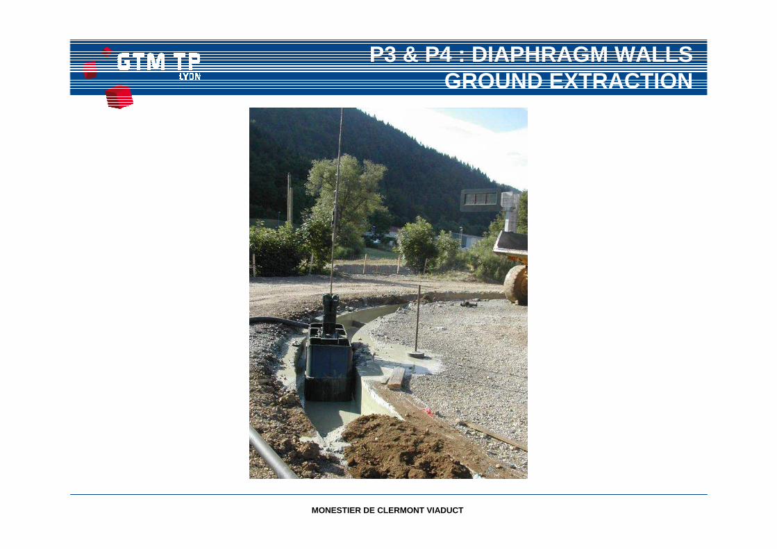
P3 & P4 : DIAPHRAGM WALLS GROUND EXTRACTION
MONESTIER DE CLERMONT VIADUCT
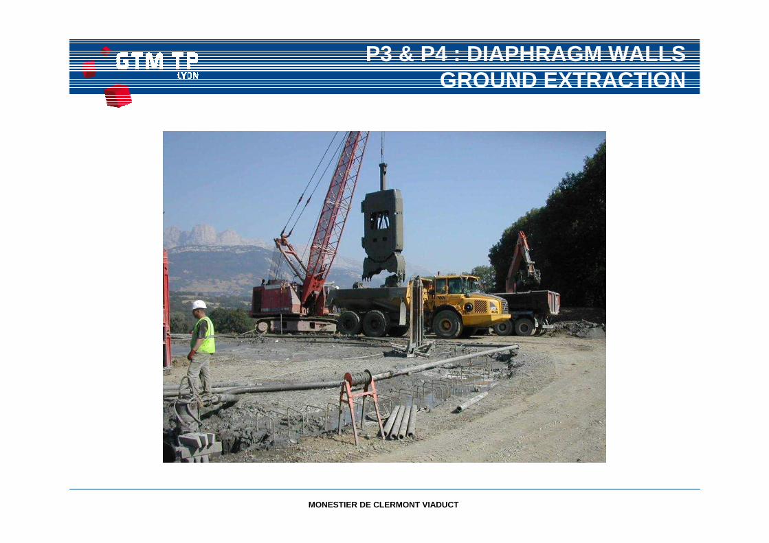
P3 & P4 : DIAPHRAGM WALLS GROUND EXTRACTION
MONESTIER DE CLERMONT VIADUCT
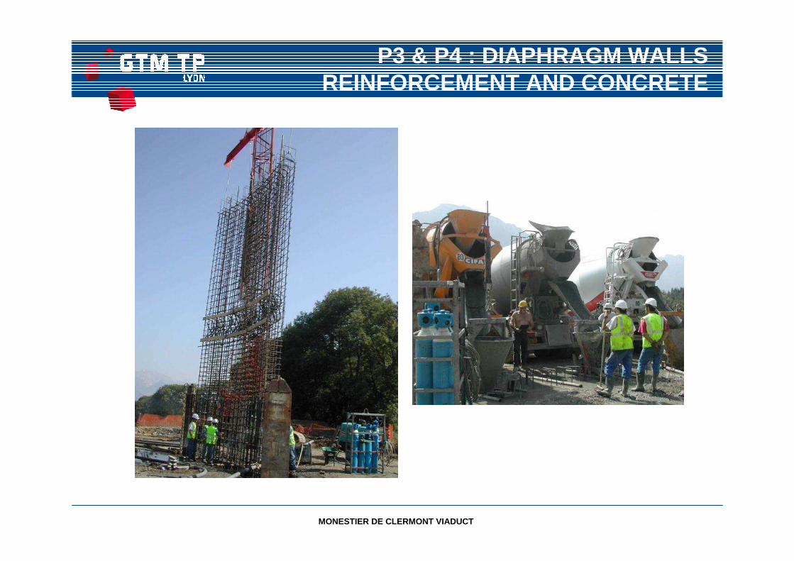
P3 & P4 : DIAPHRAGM WALLS REINFORCEMENT AND CONCRETE
MONESTIER DE CLERMONT VIADUCT
P3 & P4 : STEEL PROFILESDRIVEN INTO CLAY (STAGE 1)
MONESTIER DE CLERMONT VIADUCT
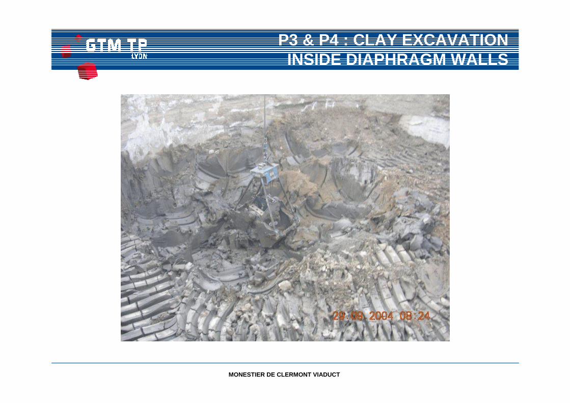
P3 & P4 : CLAY EXCAVATIONINSIDE DIAPHRAGM WALLS
MONESTIER DE CLERMONT VIADUCT
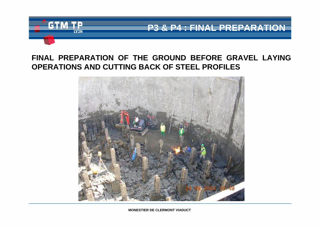
P3 & P4 : FINAL PREPARATION
FINAL PREPARATION OF THE GROUND BEFORE GRAVEL LAYING OPERATIONS AND CUTTING BACK OF STEEL PROFILES
MONESTIER DE CLERMONT VIADUCT
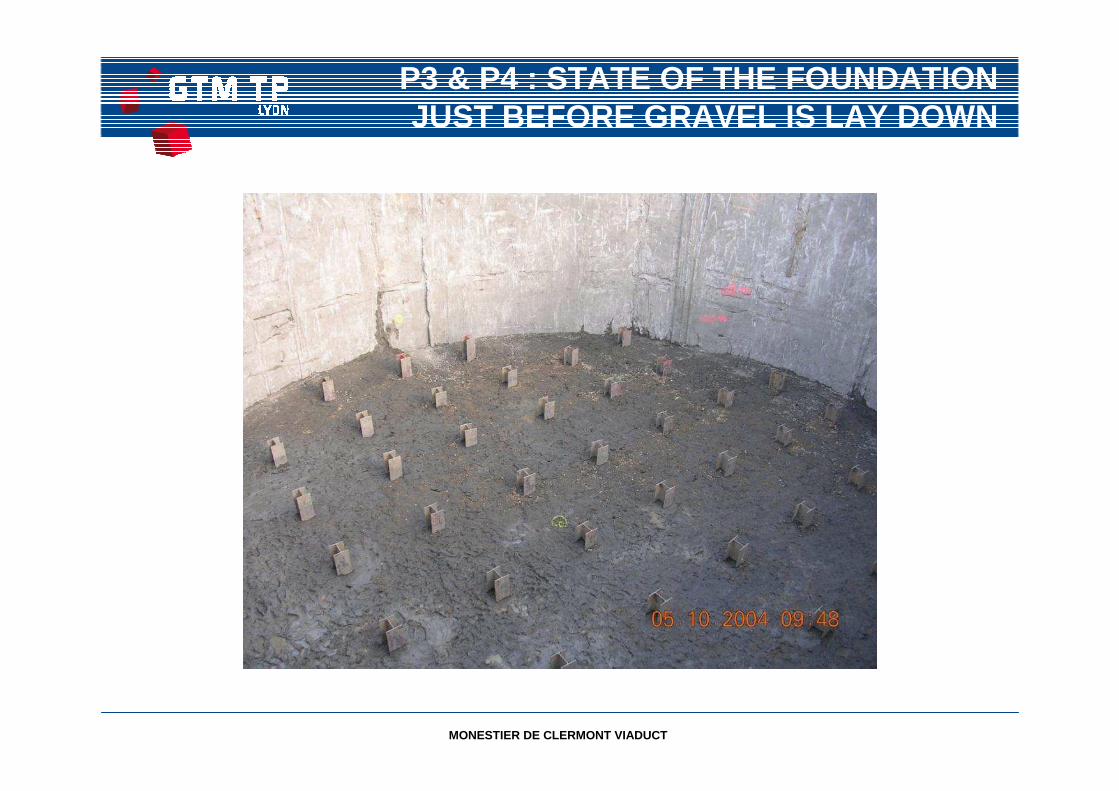
P3 & P4 : STATE OF THE FOUNDATION JUST BEFORE GRAVEL IS LAY DOWN
MONESTIER DE CLERMONT VIADUCT
P3 & P4 : GRAVEL LAYER AND PIEZOMETER IN PLACE
MONESTIER DE CLERMONT VIADUCT
P3 & P4 : REINFORCEMENT OF CONCRETE SLAS
MONESTIER DE CLERMONT VIADUCT
P3 & P4 : STIFFENING STRUCTURE WALLS
MONESTIER DE CLERMONT VIADUCT
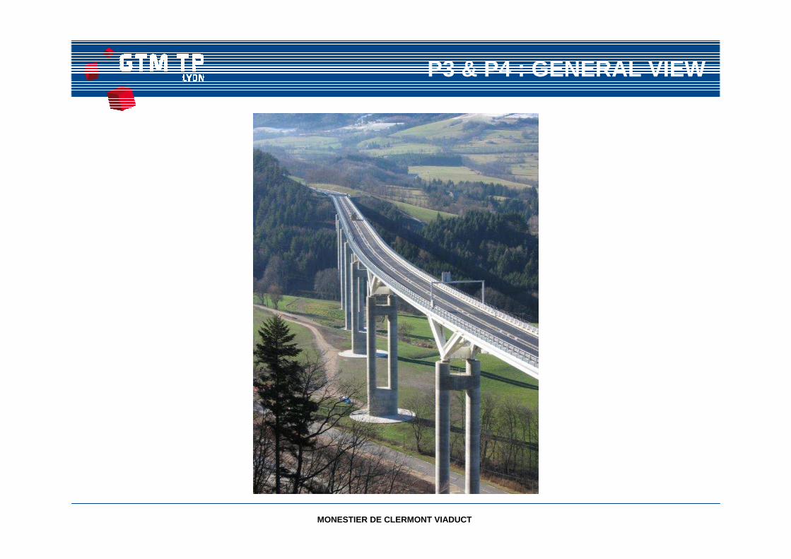
P3 & P4 : GENERAL VIEW
MONESTIER DE CLERMONT VIADUCT
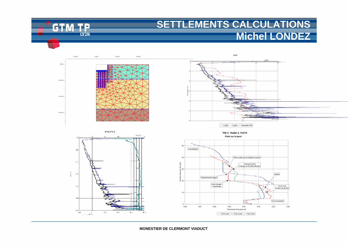
SETTLEMENTS CALCULATIONSMichel LONDEZ
¨Pile 3 - Radier à -7m/TN
0
10
20
30
40
50
-0,09 -0,07 -0,05 -0,03 -0,01 0,01 0,03 0,05
Tassements de la paroi (m)
Num
éro
de
s p
as d
e ca
lcu
l
P3C1CasA P3C1CasB P3C1CasC
Fin d 'excavation
Fin de mise en place du gravier
Radier
Avant clavage+remplissage
Relachemenent nappe
Ouvrage terminéVidange de la fouille effectuée
Mise en place de la charge de service
Consolidation
Point sur la paroi
-20.000 0.000 20.000 40.000
-60.000
-40.000
-20.000
0.000
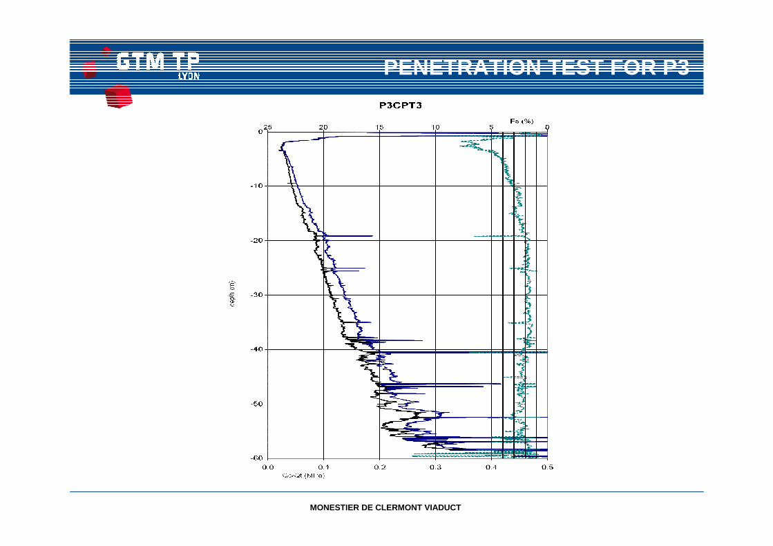
P3CPT3
- 60
- 50
- 40
- 30
- 20
- 10
00 50 100 150 200
Cu (kPa)
Pro
fond
eur
(m)
C (qt/12) C (qt/10) Pressiomètre P3S2
MONESTIER DE CLERMONT VIADUCT
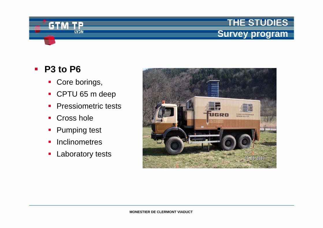
THE STUDIESSurvey program
� P3 to P6� Core borings,
� CPTU 65 m deep
� Pressiometric tests
� Cross hole
� Pumping test
� Inclinometres
� Laboratory tests
MONESTIER DE CLERMONT VIADUCT
MAIN RESULTS
� Accross the valley:
� South west area:
- Rock at 50 m.
- Fluvio-glacial permeable till between 40 à 50 m
- Gravelly clays below soft and remolded clays
� Centre and north of the valley:
- Deepening of rock (P2)
- Argiles homogeneous clays at the surface, varved b elow

MONESTIER DE CLERMONT VIADUCT
GEOLOGICAL PROFILE
Che
min
de fe
r
Rock
Rock
Geological Cross
section
Rock
Morainesgrey clay
Varved stiffer clay
Rock
varved clayClay and blocks
ClSliding Areay and blocks
MONESTIER DE CLERMONT VIADUCT
PENETRATION TEST FOR P3
MONESTIER DE CLERMONT VIADUCT
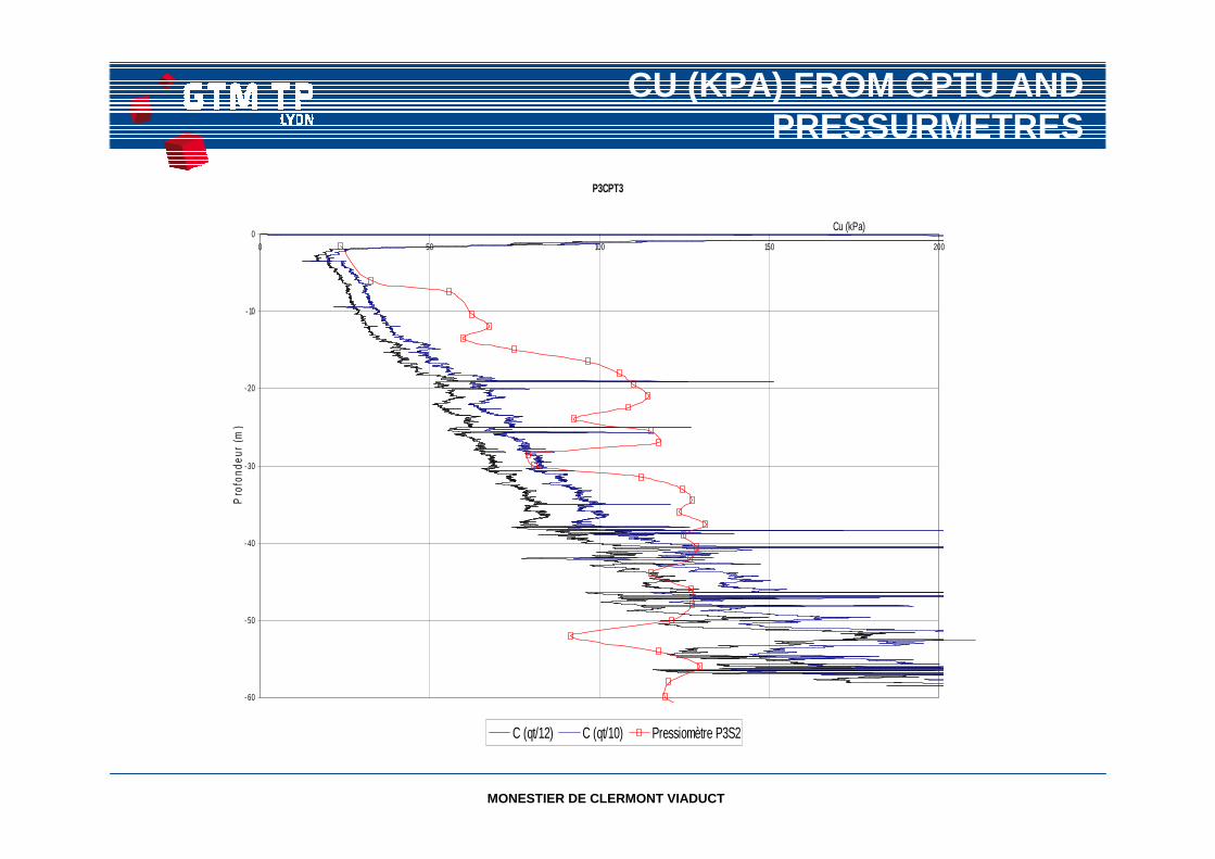
CU (KPA) FROM CPTU AND PRESSURMETRES
P3CPT3
- 60
- 50
- 40
- 30
- 20
- 10
00 50 100 150 200
Cu (kPa)P
rofo
ndeu
r (m
)
C (qt/12) C (qt/10) Pressiomètre P3S2
MONESTIER DE CLERMONT VIADUCT
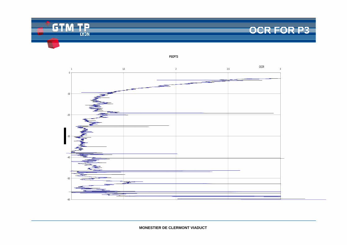
OCR FOR P3
P3CPT3
- 60
- 50
- 40
- 30
- 20
- 10
0
1 1,5 2 2,5 3OCR
MONESTIER DE CLERMONT VIADUCT
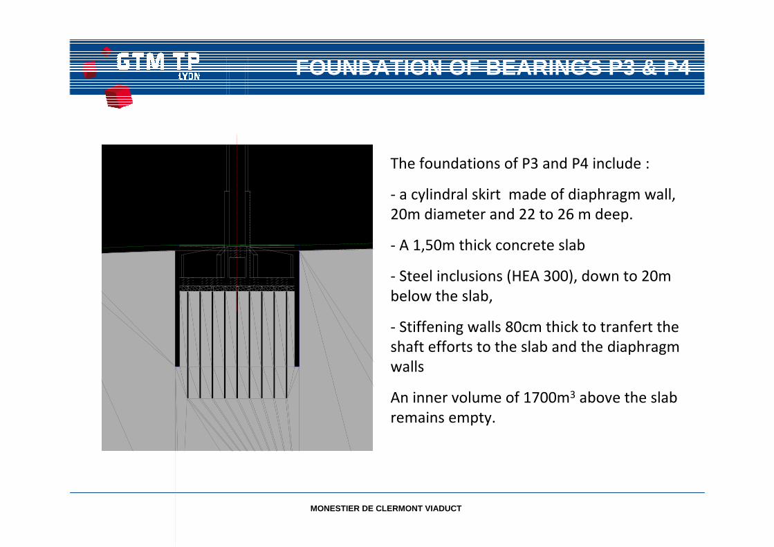
FOUNDATION OF BEARINGS P3 & P4
The foundations of P3 and P4 include :
- a cylindral skirt made of diaphragm wall,
20m diameter and 22 to 26 m deep.
- A 1,50m thick concrete slab
- Steel inclusions (HEA 300), down to 20m
below the slab,
- Stiffening walls 80cm thick to tranfert the
shaft efforts to the slab and the diaphragm
walls
An inner volume of 1700m3 above the slab
remains empty.

MONESTIER DE CLERMONT VIADUCT
Steel profiles setting out

MONESTIER DE CLERMONT VIADUCT
PARAMETRES OF CALCULATIONS
Strength
Volumetric mass(KN/M3)
C’(KN/M2) φ’(°) OCR
Depth
(m)Type of soil
18.5 5 24σ’0+50 KN/M2
0 - 18 Upper clay
18.5 0 24 σ’018 –
37/55Medium clay
18.5 10 301.2 σ’0 37/55 -
80Lower clay
MONESTIER DE CLERMONT VIADUCT
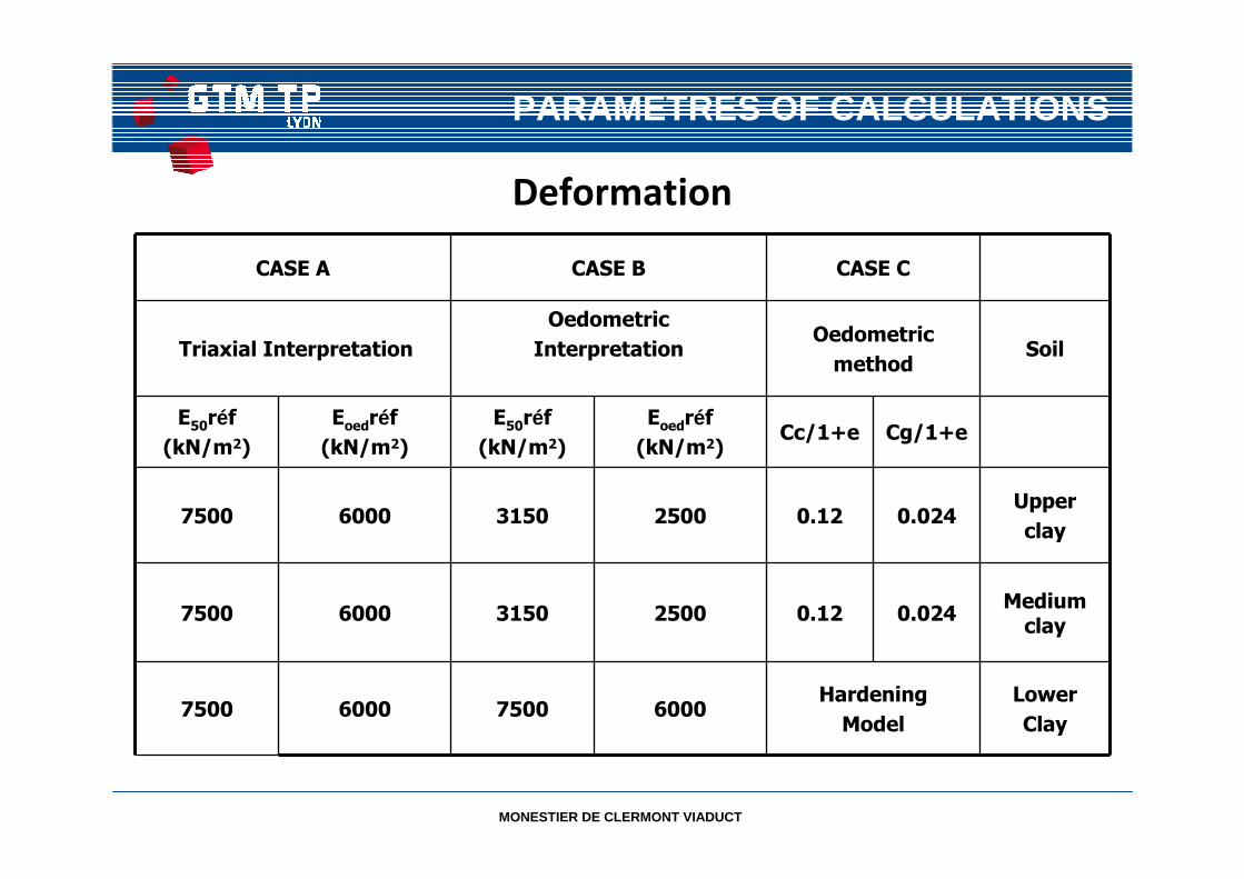
PARAMETRES OF CALCULATIONS
Deformation
CASE A CASE B CASE C
Triaxial Interpretation
Oedometric
InterpretationOedometric
methodSoil
E50réf
(kN/m2)
Eoedréf
(kN/m2)
E50réf
(kN/m2)
Eoedréf
(kN/m2)Cc/1+e Cg/1+e
7500 6000 3150 2500 0.12 0.024Upper
clay
7500 6000 3150 2500 0.12 0.024Medium
clay
7500 6000 7500 6000Hardening
Model
Lower
Clay
MONESTIER DE CLERMONT VIADUCT
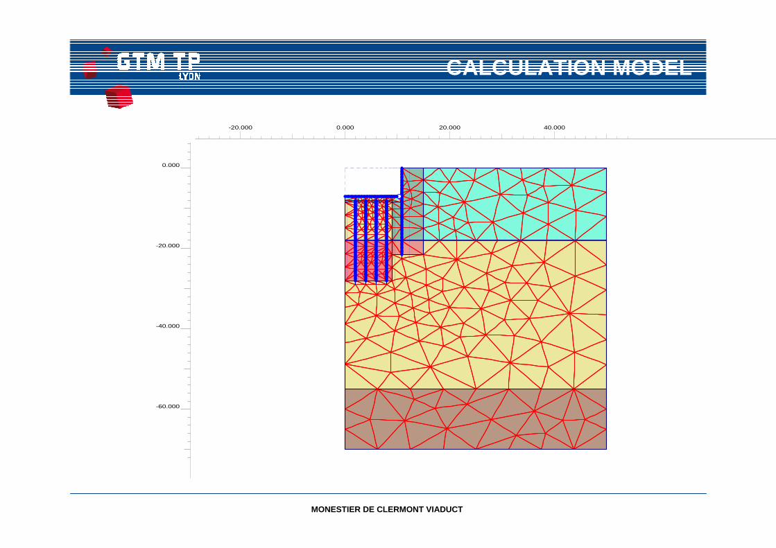
CALCULATION MODEL
-20.000 0.000 20.000 40.000
-60.000
-40.000
-20.000
0.000
MONESTIER DE CLERMONT VIADUCT
SEQUENCES OF CALCULATIONS
• Excavation of a mass of soil close to the estimated load brought by the pier
• Inclusions to control the soil relaxation , reduce the recompression
settlement
• Maximum loads during construction ( pre-loading with water)
• After final bearings installation, settlements calculations under final loads and
surcharges, consolidation.
• Acceptable differential settlements between piers: 6 cm.
MONESTIER DE CLERMONT VIADUCT
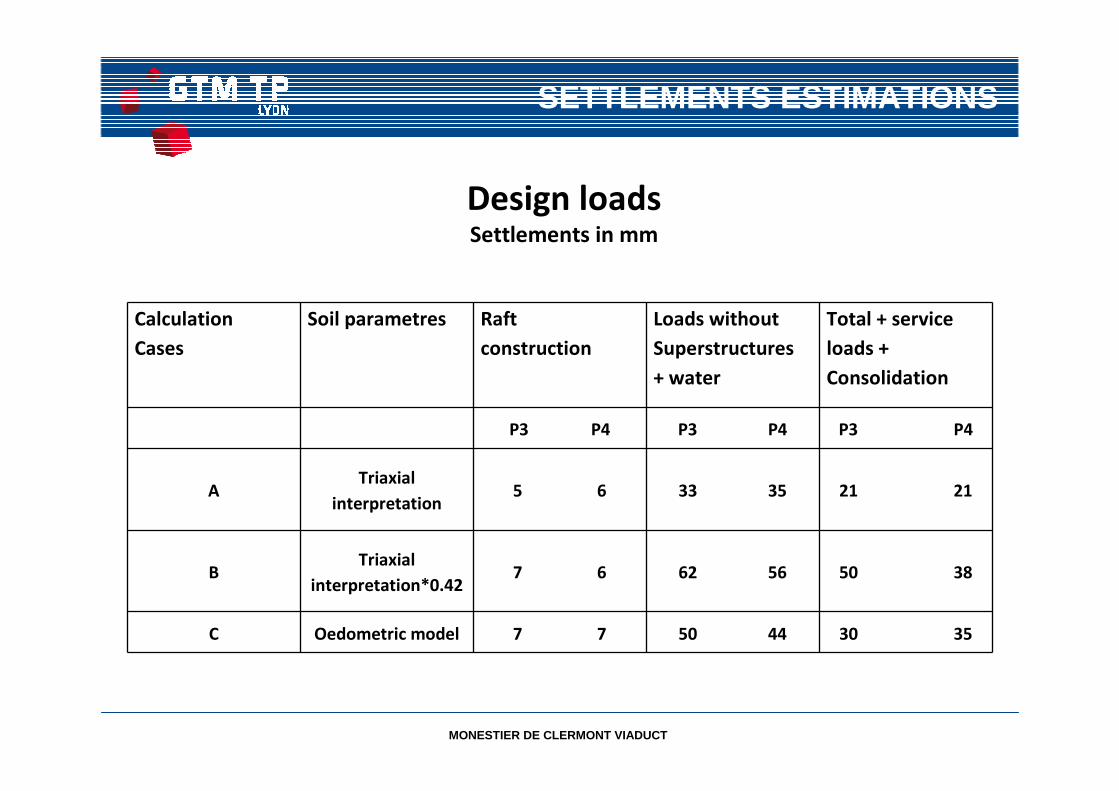
SETTLEMENTS ESTIMATIONS
Calculation
Cases
Soil parametres Raft
construction
Loads without
Superstructures
+ water
Total + service
loads +
Consolidation
P3 P4 P3 P4 P3 P4
ATriaxial
interpretation5 6 33 35 21 21
BTriaxial
interpretation*0.427 6 62 56 50 38
C Oedometric model 7 7 50 44 30 35
Design loadsSettlements in mm

MONESTIER DE CLERMONT VIADUCT
PARAMETRES OF CALCULATIONS
Deformation
CASE A CASE B CASE C
Triaxial Interpretation
Oedometric
InterpretationOedometric
methodSoil
E50réf
(kN/m2)
Eoedréf
(kN/m2)
E50réf
(kN/m2)
Eoedréf
(kN/m2)Cc/1+e
Cg/1+e
7500 6000 3150 2500 0.12 0.024Upper
clay
7500 6000 3150 2500 0.12 0.024Medium
clay
7500 6000 7500 6000Hardening
Model
Lower
Clay
MONESTIER DE CLERMONT VIADUCT
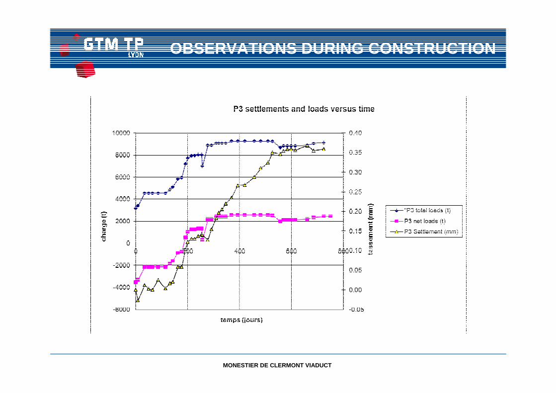
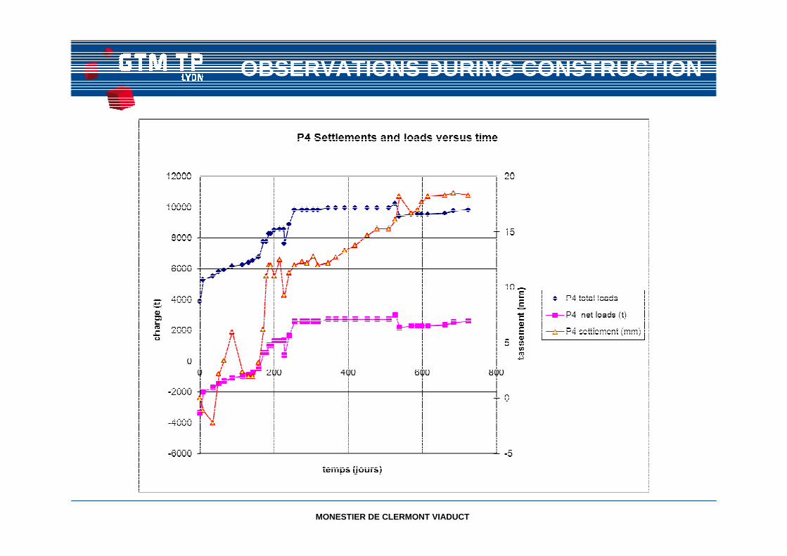
OBSERVATIONS DURING CONSTRUCTION
MONESTIER DE CLERMONT VIADUCT
OBSERVATIONS DURING CONSTRUCTION
MONESTIER DE CLERMONT VIADUCT
COMMENTS
• For P3, settlements during construction were close or slightly higher than those
estimated with the triaxial interpretation (case A)
• Needs for setlements reductions have been estimated necessary
• Adaptations of the design have been done:
- Preload with water, removed when superstructures have been completed.
- Deck level set out 20 mm above designed level to increase the acceptable differencial
settlements to 80 mm instead of 60 mm initialy considered in the design.
• For P4, the setlements are much lower due to the longer length of the diaphragm wall
skirt.
MONESTIER DE CLERMONT VIADUCT
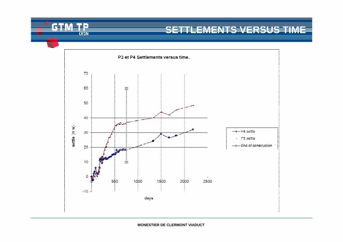
SETTLEMENTS VERSUS TIME
MONESTIER DE CLERMONT VIADUCT
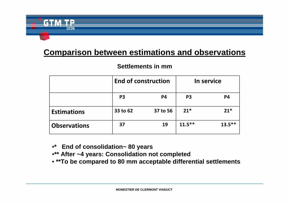
Comparison between estimations and observations
End of construction In service
P3 P4 P3 P4
Estimations 33 to 62 37 to 56 21* 21*
Observations 37 19 11.5** 13.5**
•* End of consolidation~ 80 years •** After ~4 years: Consolidation not completed • **To be compared to 80 mm acceptable differential s ettlements
Settlements in mm