Embed Size (px)
Citation preview
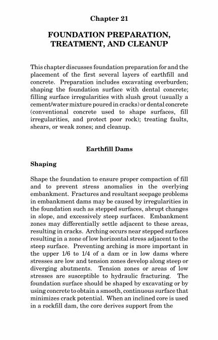
Chapter 21
FOUNDATION PREPARATION,TREATMENT, AND CLEANUP
This chapter discusses foundation preparation for and theplacement of the first several layers of earthfill andconcrete. Preparation includes excavating overburden;shaping the foundation surface with dental concrete;filling surface irregularities with slush grout (usually acement/water mixture poured in cracks) or dental concrete(conventional concrete used to shape surfaces, fillirregularities, and protect poor rock); treating faults,shears, or weak zones; and cleanup.
Earthfill Dams
Shaping
Shape the foundation to ensure proper compaction of filland to prevent stress anomalies in the overlyingembankment. Fractures and resultant seepage problemsin embankment dams may be caused by irregularities inthe foundation such as stepped surfaces, abrupt changesin slope, and excessively steep surfaces. Embankmentzones may differentially settle adjacent to these areas,resulting in cracks. Arching occurs near stepped surfacesresulting in a zone of low horizontal stress adjacent to thesteep surface. Preventing arching is more important inthe upper 1/6 to 1/4 of a dam or in low dams wherestresses are low and tension zones develop along steep ordiverging abutments. Tension zones or areas of lowstresses are susceptible to hydraulic fracturing. Thefoundation surface should be shaped by excavating or byusing concrete to obtain a smooth, continuous surface thatminimizes crack potential. When an inclined core is usedin a rockfill dam, the core derives support from the
FIELD MANUAL
322
underlying filter and transition material. The zonebeneath the filter and transition should be shaped usingcore contact criteria.
Foundation outside the core contact must be shaped tofacilitate fill placement and compaction, and unsuitableweak or compressible materials must be removed.Impervious materials beneath drainage features whichwould prevent drainage features from properlyfunctioning must also be removed. Materials may moveinto the foundation, and erodible foundation materialsmay move into the embankment. Appropriately gradedfilters between the drainage materials and foundationmay be necessary.
The minimum treatment of any foundation consists ofstripping or removing organic material such as roots andstumps, sod, topsoil, wood, trash, and other unsuitablematerials. Cobbles and boulders may also requireremoval depending on the type of embankment materialto be placed.
The weak points in earthfill dams are generally withinthe foundation and especially at the contact of thefoundation with the embankment. Foundation seepagecontrol and stability features must be carefully supervisedby the inspection force during construction to ensureconformance with the design, specifications, and goodpractice. Water control methods used in connection withexcavating cutoff trenches or stabilizing the foundationsshould ensure that fine material is not washed out of thefoundation because of improper screening of wells andthat the water level is far enough below the foundationsurface to permit construction “in the dry.” Wheneverpossible, locate well points and sumps outside the area tobe excavated to avoid loosening soil or creating a "quick"bottom caused by the upward flow of water or equipment
FOUNDATION PREPARATION
323
vibration. Avoid locating sumps and associated drainagetrenches within the impervious zone because of thedifficulty in properly grouting them after fill placementand the danger of damaging the imperviouszone/foundation contact.
Found cutoff walls or concrete grout caps in the best rockavailable. Prohibit or strictly control blasting for theexcavation of these structures to avoid damaging thefoundation. If the material cannot be excavated with ahydraulic excavator fitted with a rock bucket, a grout capor cutoff wall is probably not needed and grout nipplescan be set directly in the foundation. A highly weatheredzone can be grouted effectively by:
• Leaving the foundation high.
• Setting grout nipples through the unsuitablematerial. Long grout nipples may be necessary inpoor rock.
• Excavating to final foundation grade aftergrouting.
In hard, sound rock, neither a grout cap nor a high foun-dation is necessary.
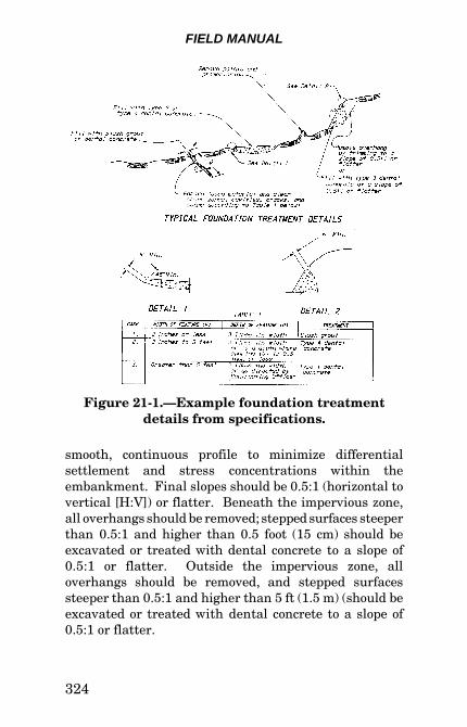
When overburden is stripped to rock, carefully clean therock surface and all pockets or depressions of soil and rockfragments before the embankment is placed. This mayrequire compressed air or water cleaning and handwork.Rock surfaces that slake or disintegrate rapidly onexposure must be protected or covered immediately withembankment material or concrete. Foundation rockshould be shaped to remove overhangs and steep surfaces(figure 21-1). High rock surfaces must be stable duringconstruction and should be cut back to maintain a
FIELD MANUAL
324
Figure 21-1.—Example foundation treatmentdetails from specifications.
smooth, continuous profile to minimize differentialsettlement and stress concentrations within theembankment. Final slopes should be 0.5:1 (horizontal tovertical [H:V]) or flatter. Beneath the impervious zone,all overhangs should be removed; stepped surfaces steeperthan 0.5:1 and higher than 0.5 foot (15 cm) should beexcavated or treated with dental concrete to a slope of0.5:1 or flatter. Outside the impervious zone, alloverhangs should be removed, and stepped surfacessteeper than 0.5:1 and higher than 5 ft (1.5 m) (should beexcavated or treated with dental concrete to a slope of0.5:1 or flatter.
FOUNDATION PREPARATION
325
Slush grout or joint mortar should be used to fill narrowcracks in the foundation (figure 21-1). However, theyshould not be used to cover exposed areas of thefoundation. Slush grout and joint mortar are composed ofPortland cement and water or, in some cases, Portlandcement, sand, and water. The slush grout is preferablyused just before fill placement to eliminate any tendencyfor hardened grout to crack under load. Dental concreteshould be used to fill potholes and grooves created bybedding planes and other irregularities such as previouslycleaned shear zones and large joints or channels in rocksurfaces. Formed dental concrete can be used to filletsteep slopes and fill overhangs.
Care should be used during all blasting to excavate or toshape rock surfaces. Controlled blasting techniques, suchas line drilling and smooth blasting, should be used.
Soil Foundations
When the foundation is soil, all organic or otherunsuitable materials, such as stumps, brush, sod, andlarge roots, should be stripped and wasted. Strippingshould be performed carefully to ensure the removal of allmaterial that may be unstable because of saturation,shaking, or decomposition; all material that may interferewith the creation of a proper bond between the foundationand the embankment; and all pockets of soil significantlymore compressible than the average foundation material.Stripping of pervious materials under the pervious orsemipervious zones of an embankment should be limitedto the removal of surface debris and roots unless materialremoval is required for seismic stability. Test pits shouldbe excavated if the stripping operations indicate the pres-ence of unstable or otherwise unsuitable material.
FIELD MANUAL
326
Before placing the first embankment layer (lift) on anearth foundation, moistening and compacting the surfaceby rolling with a tamping roller is necessary to obtainproper bond. An earth foundation surface sometimesrequires scarification by disks or harrows to ensure properbonding. No additional scarification is usually necessaryif the material is penetrated by tamping rollers.
All irregularities, ruts, and washouts should be removedto provide a satisfactory foundation. Cut slopes should beflat enough to prevent sloughing, and not steeper than1:1. Material that has been loosened to a depth of lessthan 6 in (15 cm) may be treated by compaction.Loosened material deeper than 6 in (15 cm) cannot beadequately compacted and should be removed.
Foundation materials at the core/foundation contact mustbe compacted to a density compatible with the overlyingfill material. A fine-grained foundation should be com-pacted and disked to obtain good mixing and bondbetween the foundation and the first lift of core material.
Fine-grained foundations should be compacted with aroller. If the foundation is too firm for the tamping feet topenetrate, the foundation surface should be disked to adepth of 6 in and moistened before compaction. Smoothsurfaces created by construction traffic on a previouslycompacted foundation surface should be disked to a depthof 2 in (5 cm).
Coarse-grained foundations should be compacted byrubber-tired or vibratory rollers. Vibratory compactorscreate a more uniform surface for placement of the firstearthfill and are the preferred method of compaction.
Cemented and highly overconsolidated soils that breakinto hard chunks should not be reworked or disked to mix
FOUNDATION PREPARATION
327
foundation and core material. The first lift ofembankment material should be placed in a mannersimilar to that required for rock foundations as describedabove.
Soil foundation compaction requirements beneath filterand shell zones should be the same as those outlinedabove, except bonding the foundation to the overlying fillis not required.
The moisture content of the upper 6 in (15 cm) of a fine-grained soil foundation should be within 2 percent dryand 1 percent wet of the Proctor optimum moisturecontent for adequate compaction. Coarse-grainedfoundation materials should be just wet enough to permitcompaction to the specified relative density, butsaturation is not permitted. Dry materials must bedisked and moistened to provide a homogeneous moisturecontent within the specified limits in the upper 6 in(15 cm) of the foundation. Wet materials must be dried bydisking to bring the upper 6 in of foundation materia1within the specified moisture content limits. Wetfoundations should be unwatered or dewateredsufficiently to prevent saturation of the upper 6 in (15 cm)of foundation material due to capillary rise or pumpingcaused by construction equipment travel.
All embankment materials should be protected fromeroding into coarser soil zones in the foundation bytransitions satisfying filter criteria or by select zones ofhighly plastic, nonerodible material. Transition zones orfilters on the downstream face of the cutoff trench andbeneath the downstream zones should prevent movementof fine material in the foundation into the embankment.Dispersive embankment materials must be protected frompiping into coarse material in the foundation by placingselect zones of nondispersive material between the
FIELD MANUAL
328
embankment and foundation. Lime-treated or naturallynondispersive earthfill is appropriate for the first severallifts of fill material or filters. Except for areas where animpervious seal between the embankment and foundationis required, filter zone(s) are the preferred method.
Rock Foundations
Rock foundation surfaces should be moistened, but nostanding water should be permitted when the first lift isplaced. The use of very wet soil for the first lift againstthe foundation should generally be avoided, but havingthe soil slightly wet of optimum moisture content isbetter. Any material more plastic than what is typicallyavailable for embankment construction is commonly usedon the first few lifts. The foundation should be properlymoistened to prevent drying of the soil. On steep,irregular rock abutments, material slightly wetter thanoptimum may be necessary to obtain good workability anda suitable bond. Be careful when special compaction isused to ensure that suitable bonds are created betweensuccessive layers of material. This usually requires lightscarification between lifts of compacted material. Wherea rock foundation would be damaged by penetration of thetamping roller feet, the first compacted lift can be thickerthan that specified. The first lift thickness should neverexceed 15 in (40 cm) loose for 9-in-long (23-cm) tamperfeet, and additional roller passes are probably required toensure proper compaction. Special compaction methods,such as hand tamping, should be used in pockets thatcannot be compacted by roller instead of permitting anunusually thick initial lift to obtain a uniform surface forcompaction. Irregular rock surfaces may prevent propercompaction by rollers, and hand compaction may benecessary. However, where foundation surfaces permit,a pneumatic-tire roller or pneumatic-tire equipmentshould be used near foundation contact surfaces. An
FOUNDATION PREPARATION
329
alternative to using thick lifts is using a pneumatic-tireroller or loader with a full bucket and disking orscarifying the lift surfaces to obtain a bond between lifts.The tamping roller can be used when the fill is sufficientlythick and regular to protect the foundation from thetamping feet. Unit weight and moisture should becarefully monitored in the foundation contact zone, andplacing and compacting operations should be carefullyinspected.
On steep surfaces, ramping the fill aids compaction; abouta 6:1 slope should be used for ramping the fill. Thesurfaces of structures should be sloped (battered) at about1:10 to facilitate compaction.
The basic objectives of foundation surface treatmentwithin the impervious core are:
• Obtain a good bond between the impervious corematerials and the foundation. The foundationsurface must be shaped by excavation or concreteplacement to provide a surface suitable forearthfill compaction. Compaction techniques usedfor initial earthfill placement should result inadequately compacted embankment material inintimate contact with and tightly bonded to thefoundation without damaging the foundationduring placement of the first lifts. A plasticmaterial is preferred next to the foundation, andspecial requirements on the plasticity, gradation,and moisture content are commonly specified.
• Defend against erosion of embankment materialsinto the foundation by filling or covering surfacecracks in the foundation, using blanket grouting,protective filters, and nonerodible embankment
FIELD MANUAL
330
materials (natural or manufactured) at thefoundation contact.
• Remove erodible, weak, unstable, compressible,loose, or pervious materials to ensure afoundation of adequate strength and appropriatepermeability. When in doubt, take it out. In rockfoundations, defects such as faults, fractures,erosion channels, or solution cavities or channelssometimes cannot be completely removed.Material defects in the rock mass include faultgouge, rock fragments, soft or pervious soil, orsolutioned rock. These materials require removalto an adequate depth and replacement with slushgrout, dental concrete, or specially compactedearthfill.
How the exposed rock surface is treated after removal ofunsuitable overlying materials depends on the type ofrock and the irregularities present. Construction activ-ities such as using tracked equipment on soft rocksurfaces, using rippers near foundation grade, or nearbyblasting may loosen rock or open joints in originallysatisfactory rock. This type of damage should and can beavoided to limit excavation and cleanup. Theconfiguration of exposed rock surfaces is controlled largelyby bedding, joints, other discontinuities, and excavationmethods. Depending on discontinuity orientations, thesefeatures can result in vertical surfaces, benches,overhangs, or sawteeth. Features such as potholes,buried river channels, solution cavities, and shear zonescan create additional irregularities requiring treatment.Unsuitable material must be removed from theirregularities, and the foundation surface must be shapedto provide a sufficiently regular surface that earthfill canbe placed without differential settlement. If theirregularities are small enough and discontinuous both
FOUNDATION PREPARATION
331
horizontally and vertically, overexcavation can beappropriate. Generally, the foundation surface can beshaped adequately by conventional excavation or smoothblasting. When smoothing of irregularities requiresexcessively large quantities of excavation or requiresblasting that may damage the foundation, shaping withdental concrete may be appropriate.
High rock surfaces must be stable during constructionand must be laid back to maintain a smooth, continuousprofile to minimize differential settlement and stressconcentrations. Slopes should be 0.5:1 (H:V) or flatter,depending on the fill material.
Remove overhangs. Stepped surfaces that are steeperthan 0.5:1 and higher than 1 foot (30 cm) should beexcavated or treated with dental concrete to a resultantslope of 0.5:1 or flatter, depending on the fill material(figure 21-1). In the lower portions of a high dam, thisrequirement may be relaxed. For example, a verticalsurface less than 20 ft (6.1 m) long and 5 ft (1.5 m) highmight be tolerated if the surface is well within theimpervious zone.
Remove all overhangs under the outer zones of earthfilldams and under transitions and filters of rockfill dams.Stepped surfaces that are steeper than 0.5:1 and higherthan 5 ft (1.5 m) should be flattened or treated withdental concrete to a slope of 0.5:1 or flatter. Beneath theouter rockfill zones of rockfill dams, nearly verticalabutment contact slopes have been permitted in high,steep-walled canyons. Overhangs should be trimmed orthe undercut below the overhang filled with concrete.
If shaping requires blasting, proper blasting proceduresare essential to ensure that the permeability and strengthof the rock is not adversely affected and that the rock can
FIELD MANUAL
332
stand on the slopes and handle the imposed loads.Existing fractures and joints in a rock mass, as well aspoor blasting, often result in unacceptable excavatedsurfaces. Prior competent review, approval, and enforce-ment of the Contractor’s blasting plan, control of blastingdetails, requirements for acceptabi1ity of the excavatedsurface, and control of vibration levels can help obtain thedesired excavation surface.
All loose or objectionable material should be removed byhandwork, barring, picking, brooming, water jetting, orair jetting. Remove accumulated water from cleaningoperations. When the rock surface softens or slakes bywater washing, compressed-air jetting or jetting with asmall amount of water added to the air should be used.Loose or unsuitable material in cavities, shear zones,cracks, or seams should be treated as follows (figure 21-1):
• Openings narrower than 2 in (5 cm) should becleaned to a depth of three times the width of theopening and treated.
• Openings wider than 2 in (5 cm) and narrowerthan 5 ft (1.5 m) should be cleaned to a depth ofthree times the width of the opening or to a depthwhere the opening is 0.5 in (12mm) wide or less,but not to a depth exceeding 5 ft (5 cm) andtreated.
• Openings wider than 5 ft (1.5 m) are a special casewhere the required depth of cleaning andtreatment is determined in the field.
Special cleanup procedures are required for foundationmaterials that deteriorate when exposed to air or water(slake). The foundation must be kept moist if deteriora-tion is caused by exposure to air and kept dry if
FOUNDATION PREPARATION
333
deterioration is caused by exposure to water. Spraycoating with material (similar to concrete curingcompound) designed to reduce slaking may (but probablywill not) be effective. Cleanup and placing a lean concrete“mud slab” approximately 4 in (15 cm) thick may beeffective. Usually, removing the last few inches ofmaterial and doing final cleanup just before firstplacement of fill is the best approach. A maximum timeinterval may also be specified between the time ofexposure of the final grade and the time that thefoundation is protected with earthfill or a suitableprotective coating.
Cleanup outside the core is normally less critical. Loosematerial should be removed so that the embankment is indirect contact with suitable rock. If defects are containedwithin the foundation area, they may not require cleaningand refill. If a defect crosses the entire foundation area,it may require cleaning similar to the foundation beneaththe core.
Dental concrete is used to fill or shape holes, grooves,extensive areas of vertical surfaces, and sawteeth createdby bedding planes, joints, and other irregularities such aspreviously cleaned out solution features, shear zones,large joints, or buried channels. Formed dental concretecan be used to fillet steep slopes and fill overhangs.Placing a concrete mat over a zone of closely spacedirregularities is appropriate in local areas that are notlarge in relation to the core dimensions. Dental concreteshaping can be used instead of excavation by blasting orwhen excessive amounts of excavation would otherwise berequired.
Slabs of dental concrete should have a minimumthickness of 6 in (15 cm) if the foundation is weak enoughto allow cracking of the concrete under load (figure 21-1).
FIELD MANUAL
334
Thin areas of dental concrete over rock projections on ajagged rock surface are likely places for concrete crackingand should be avoided by using a sufficient thickness ofdental concrete or by avoiding continuous slabs of concreteover areas containing numerous irregularities on weakfoundations. Feathering at the end of concrete slabs onweak foundations should not be permitted, and the edgesof slabs should be sloped no flatter than 45 degrees.Formed dental concrete should not be placed on slopesgreater than 0.5:1 (H:V). When dental concrete fillets areplaced against vertical or nearly vertical surfaces in weakrock, feathering should not be permitted, and a beveledsurface with a minimum thickness of 6 in (15 cm) isrequired at the top of the fillet.
Concrete mix proportions should provide a 28-daystrength of 3,000 pounds per square inch (21 MPa). Themaximum aggregate size should be less than one-thirdthe depth of slabs or one-fifth the narrowest dimensionbetween the side of a form and the rock surface. Cementtype will depend on the concentration of sulfates in thefoundation materials and groundwater. Low-alkalicement is required for alkali-reactive aggregates. Cementtype should be the same as used in structural concrete onthe job. Aggregate and water quality should be equal tothat required in structural concrete.
The rock surface should be thoroughly cleaned, asdescribed below, and moistened before concrete placementto obtain a good bond between the concrete and the rocksurface. When overhangs are filled with dental concrete,the concrete must be well bonded to the upper surface ofthe overhang. The overhang should be shaped to allow airto escape during concrete placement to prevent air pocketsbetween the concrete and the upper surface of theoverhang. The concrete must be formed and placed sothat the head of the concrete is higher than the upper
FOUNDATION PREPARATION
335
surface of the overhang. If this is impractical, grout pipesshould be installed in the dental concrete for later fillingof the air voids. If grouting through dental concrete isdone, pressures should be closely controlled to preventjacking the concrete or fracturing the fill.
Finished horizontal dental concrete slabs should have aroughened, broomed finish for satisfactory bonding of fillto concrete. Dental concrete should be cured by water oran approved curing compound for 7 days or covered byearthfill. Earthfill placement may not be permitted overdental concrete for a minimum of 72 hours or more afterconcrete placement to allow concrete time to developsufficient strength to withstand stress caused by placingearthfill. Inadequate curing may result in the concretecracking.
Slush grout is a neat cement grout or a sand-cementslurry that is applied to cracks in the foundation. Cracksor joints are filled with grout rather than spreading grouton the surface (figure 21-1). Slush grout should be usedto fill narrow surface cracks and not used to cover areasof the foundation. Slush grout may consist of cement andwater, or sand, cement, and water. To ensure adequatepenetration of the crack, the maximum particle size in theslush grout mixture should be no greater than one-thirdthe crack width. Generally, neat cement grout is used.The consistency of the slush grout mix may vary from avery thin mix to mortar as required to penetrate thecrack. The grout preferably should be mixed with amechanical or centrifugal mixer, and the grout should beused within 30 minutes after mixing.
The type of cement required will depend on theconcentration of sulfates in the foundation materials andgroundwater. Low-alkali cement is required for alkalisensitive aggregates. Cement type should be that
FIELD MANUAL
336
specified for structural concrete. Sand and water qualityshould be equal to that required for structural concrete.
Clean out cracks as described above. All cracks should bewetted before placing slush grout. Slush grout may beapplied by brooming over surfaces containing closelyspaced cracks or by troweling, pouring, rodding, orfunneling into individual cracks. Slush grout is bestapplied just before material placement so cracking willnot occur during compaction.
Shotcrete is concrete or mortar that is sprayed in place.The quality of the shotcrete depends on the skill andexperience of the crew, particularly regarding the amountof rebound, thickness, feather edges, and ensuringadequate thickness over protrusions on irregular surfaces.Untreated areas can be inadvertently covered because ofthe ease and rapidity of placement. Shotcrete should beused beneath impervious zones only when site conditionspreclude using dental concrete. If shotcrete is used, closeinspection and caution are necessary. Shotcrete is anacceptable alternative to dental concrete outside the corecontact area.
The fill compaction method used depends on the steepnessof the surface, the nature of the irregularities in thefoundation surface, and the soil material.
A hand tamper may be used to compact earthfill in oragainst irregular surfaces on abutments, in potholes anddepressions, and against structures not accessible toheavy compaction equipment. Hand-tamped, speciallycompacted earthfill is typically placed in 4-in (10-cm)maximum compacted lifts with scarification between lifts.
FOUNDATION PREPARATION
337
Site-specific conditions determine whether hand-compacted earthfill or filling with dental concrete is thebest solution.
The feet of the roller must not penetrate the first layer ofearthfill and damage the foundation. Penetration can beprevented by using a rubber-tired roller or loader tocompact the first few lifts above the foundation surfacewith scarification between lifts. Earthfill speciallycompacted by pneumatic-tired equipment is typicallyplaced in 6-in (15-cm) maximum compacted lifts.Placement of horizontal lifts against mildly sloping rocksurfaces can result in feathering of the earthfill lift nearthe rock contact. Placement of the initial lift parallel tothe foundation surface (as opposed to a horizontal lift) forfoundation surfaces flatter than 10:1 (H:V) is acceptableif the compactor climbing up the slope does not loosen ordisturb the previously compacted earthfill.
Core material compacted against steep surfaces istypically placed in 6-in (15-cm) compacted lifts withscarification between lifts. Earthfill 8 to 10 ft (2.4 to 3 m)from a steep surface should be ramped toward the steepsurface at a slope of 6:1 to 10:1 so that a component of thecompactive force acts toward the steep surface.
Earthfill placed against irregular surfaces should beplastic and deformable so that the material is forced(squished) into all irregularities on the foundation surfaceby compaction or subsequent loading. The first layer soilmoisture contents should range from 0 to 2 percent wet ofoptimum. Select material with a required plasticity rangeis commonly specified. A soil plasticity index rangingfrom 16 to 30 is preferred although not absolutelynecessary.
FIELD MANUAL
338
Core materials that are erodible include low plasticity ornonplastic, silty materials and dispersive clays.Preventing erosion of embankment materials into thefoundation includes sealing cracks in the foundation withslush grout and dental concrete and using filter zone(s)between the fine-grained material and the foundation.Sealing cracks is not totally reliable because concrete andmortar can crack due to shrinkage or loading. Usingnatural or manufactured nonerodible material for the firstseveral lifts of embankment at the core-foundation contactis good practice.
If erosion-resistant plastic materials are available, thesematerials should be used for the first several lifts alongthe foundation contact to avoid placing erodible nonplasticmaterials directly against the rock surface. If plasticmaterials are not available, the natural soil can be mixedwith sodium bentonite to produce core material to beplaced against the foundation. Laboratory testing shouldestablish the amount of sodium bentonite required to givethe soil the characteristics of a lean clay.
If nondispersive material is available, it should be usedinstead of dispersive material, at least in critical locationssuch as along the core-foundation contact. In depositscontaining dispersive material, the dispersion potentialgenerally varies greatly over short distances. Selectivelyexcavating nondispersive material from a depositcontaining dispersive materials is frequently difficult andunreliable. Lime can be added to dispersive materials toreduce or convert the soil to a nondispersive material.The amount of lime required to treat the dispersive soilshould be established by performing dispersivity tests onsamples of soils treated with varying percentages of lime.Adding lime to a soil results in reduced plasticity and amore brittle soil. The lime content should be the
FOUNDATION PREPARATION
339
minimum required to treat the soil. Do not treatmaterial that has naturally low plasticity with lime if itis not necessary.
Concrete Arch Dams
The entire area to be occupied by the base of a concretearch dam should be excavated to material capable ofwithstanding the loads imposed by the dam, reservoir,and appurtenant structures. Blasting operations mustnot damage the rock foundation. All excavations shouldconform to the lines and dimensions shown on theconstruction drawings, where practical, but it may benecessary to vary dimensions or excavation slopes becauseof local conditions.
Foundations containing seams of shale, siltstone, chalk,or mudstone may require protection against air and waterslaking or, in some environments, against freezing.Excavations can be protected by leaving a temporarycover of unexcavated material, by immediately coveringthe exposed surfaces with a minimum of 12 in (30 cm) ofconcrete, or by any other method that will preventdamage to the foundation.
Shaping
Although not considered essential, a symmetrical ornearly symmetrical profile is desirable for an arch dam forstress distribution. However, asymmetrical canyonsfrequently have to be chosen as arch dam sites. Theasymmetry may introduce stress problems, but these canbe overcome by proper design. Abutment pads betweenthe dam and foundation may be used to overcome some ofthe detrimental effects of asymmetry or foundationirregularities. Thrust blocks are sometimes used at
FIELD MANUAL
340
asymmetrical sites. The primary use of a thrust block isnot to provide symmetry but to establish an artificialabutment where a natural one does not exist.Overexcavation of a site to achieve symmetry is notrecommended. In all cases, the foundation should beexcavated in such a way as to eliminate sharp breaks inthe excavated profile because these may cause stressconcentrations in both the foundation rock and the dam.The foundation should also be excavated to about radialor part radial lines.
Dental Treatment
Exploratory drilling or final excavation often uncoversfaults, seams, or shattered or inferior rock extending todepths that are impracticable to remove. Geologicdiscontinuities can affect both the stability and thedeformation modulus of the foundation. In reality, thefoundation modulus need not be known accurately if theratio of the foundation modulus Ef to the concretemodulus Ec of the dam is known to be greater than 1:4.Canyons with extensive zones of highly deformablematerials and, consequently, Ef /Ec ratios less than 1:4should still be considered potential arch dam sites. Thedeformation modulus of weak zones can be improved byremoving sheared material, gouge, and inferior rock andreplacing the material with backfill concrete.
Analytical methods can provide a way to combine thephysical properties of different rock types and geologicdiscontinuities such as faults, shears, and joint sets intoa value representative of the stress and deformation in agiven segment of the foundation. This also permitssubstitution of backfill concrete in faults, shears, andzones of weak rock and evaluates the benefit contributedby dental treatment.
FOUNDATION PREPARATION
341
Data required for analysis are the dimensions andcomposition of the lithologic bodies and geologicdiscontinuities, deformation moduli for each of theelements incorporated into the study, and the loadingpattern imposed by the dam and reservoir.
Dental treatment concrete may also be required toimprove the stability of a rock mass. By using datarelated to the shear strength of faults, shears, joints,intact rock, pore water pressures induced by the reservoirand/or groundwater, the weight of the rock mass, and thedriving force induced by the dam and reservoir, a safetyfactor for a particular rock mass can be calculated.
Frequently, relatively homogeneous rock foundations withonly nominal faulting or shearing do not require thesophisticated analytical procedures described above. Thefollowing approximate formulas for determining the depthof dental treatment can be used:
d = 0.002 bH + 5 for H >_ 150 ft
d = 0.3b+5 for H<150 ft
where:
H = height of dam above general foundation level inft
b = width of weak zone in ftd = depth of excavation of the weak zone below the
surface of adjoining sound rock in ft. In claygouge seams, d should not be less than 0.1 H.
These rules provide an estimate of how much should beexcavated, but final decisions must be made in the fieldduring actual excavation.
FIELD MANUAL
342
Protection Against Piping
The methods described in the preceding paragraphs willsatisfy the stress, deformation, and stability requirementsfor a foundation, but the methods may not providesuitable protection against piping. Faults, shears, andseams may contain pipable material. To protect againstpiping, upstream and downstream cutoff shafts may benecessary in each seam, shear, or fault, and the shaftsbackfilled with concrete. The dimension of the shaftperpendicular to the seam should be equal to the width ofthe weak zone plus a minimum of 1 foot on each end tokey the concrete backfill into sound rock. The shaftdimension parallel to the seam should be at least one-halfthe other dimension. In any instance a minimum shaftdimension of 5 ft (1.6 m) each way should be used toprovide working space. The depth of cutoff shafts may becomputed by constructing flow nets and computing thecutoff depths required to eliminate piping.
Other adverse foundation conditions may be caused byhorizontally bedded clay and shale seams, caverns, orsprings. Procedures for treating these conditions willvary and will depend on the characteristics of theparticular condition to be remedied.
Foundation Irregularities
Although analyses and designs assume relatively uniformfoundation and abutment excavations, the finalexcavation may vary widely from that which wasassumed. Faults or crush zones are often uncoveredduring excavation, and the excavation of the unsound rockleaves depressions or holes which must be filled withconcrete. Unless this backfill concrete has undergonemost of its volumetric shrinkage at the time overlyingconcrete is placed, cracks can occur in the overlying
FOUNDATION PREPARATION
343
concrete near the boundaries of the backfill concrete asloss of support occurs because of continuing shrinkage ofthe backfill concrete. Where dental work is extensive, thebackfill concrete should be placed and cooled beforeadditional concrete is placed over the area.
Similar conditions exist where the foundation has abruptchanges in slope. At the break of slope, cracks oftendevelop because of the differential movement that takesplace between concrete held in place by rock and concreteheld in place by previously placed concrete that has notundergone its full volumetric shrinkage. A forced coolingof the concrete adjacent to and below the break in slopeand a delay in placement of concrete over the break inslope can minimize cracking at these locations. Ifeconomical, the elimination of these points of high stressconcentration is worthwhile. Cracks in lifts near theabutments very often develop leakage and lead to spallingand deterioration of the concrete.
Concrete Gravity Dams
The entire base area of a concrete gravity dam should beexcavated to material capable of withstanding the loadsimposed by the dam, reservoir, and appurtenantstructures. Blasting should not shatter, loosen, orotherwise adversely affect the suitability of the foundationrock. All excavations should conform to the lines anddimensions shown on the construction drawings, wherepracticable. Dimensions or excavation slopes may varybecause of local conditions.
Foundations such as shale, chalk, mudstone, and siltstonemay require protection against air and water slaking or,in some environments, against freezing. These excava-tions can be protected by leaving a temporary cover of
FIELD MANUAL
344
unexcavated material, by immediately applying a mini-mum of 12 in (30 cm) of mortar to the exposed surfaces, orby any other method that will prevent damage to thefoundation.
Shaping
If the canyon profile for a damsite is relatively narrowand the walls are steeply sloping, each vertical section ofthe dam from the center towards the abutments is shorterin height than the preceding one. Consequently, sectionscloser to the abutments will be deflected less by thereservoir load, and sections toward the center of thecanyon will be deflected more. Since most gravity damsare keyed at the contraction joints, a torsional effect onthe dam is transmitted to the foundation rock.
A sharp break in the excavated profile of the canyon willresult in an abrupt change in the height of the dam. Theeffect of the irregularity of the foundation rock causes amarked change in stresses in the dam and foundation andin stability factors. For this reason, the foundation shouldbe shaped so that a uniform profile without sharp offsetsand breaks is obtained.
Generally, a foundation surface will appear as horizontalin the transverse (upstream-downstream) direction.However, where an increased resistance to sliding isdesired, particularly for structures founded onsedimentary rock foundations, the surface can be slopedupward from heel to toe of the dam.
Dental Treatment
Faults, seams, or shattered or inferior rock extending todepths that are impractical to remove require specialtreatment by removing the weak material and backfilling
FOUNDATION PREPARATION
345
the resulting excavations with dental concrete. Generalrules for how deep transverse seams should be excavatedhave been formulated based on actual foundationconditions and stresses in dams. Approximate formulasfor determining the depth of dental treatment are:
d = 0.002 bH + 5 for H >_ 150 ft
d = 0.3 b + 5 for H < 150 ft
where:
H = height of dam above general foundation level infeet
b = width of weak zone in feet
d = depth of excavation of weak zone below surface ofadjoining sound rock in feet. In clay gougeseams, d should not be less than 0.1 H.
These rules provide guidance for how much should beexcavated, but actual quantities should be determined inthe field during excavation.
Although the preceding rules are suitable for foundationswith a relatively homogeneous rock foundation andnominal faulting, some damsites may have severaldistinct rock types interspersed with numerous faults andshears. The effect on the overall strength and stability ofthe foundation of rock differences complicated by largezones of faulting may require extensive analysis. Datarequired for analysis include the dimensions andcomposition of the rock mass and geologic discontinuities,deformation moduli for each of the elements incorporatedinto the study, and the loading pattern imposed on thefoundation by the dam and reservoir.
FIELD MANUAL
346
Dental treatment may also be required to improve thestability of the rock mass. A safety factor for a particularrock mass can be calculated using data related to thestrength of faults, shear zones, joints, intact rock, porewater pressures induced by the reservoir and/orgroundwater, the weight of the rock mass, and the drivingforces induced by the dam and reservoir.
Protection Against Piping
The methods discussed above can satisfy the stress,deformation, and stability requirements for a foundation,but they may not provide suitable protection againstpiping. Faults and seams may contain pipeable material,and concrete backfilled cutoff shafts may be required ineach fault or seam. The dimension of the shaftperpendicular to the seam should be equal to the width ofthe weak zone plus a minimum of 1 foot (0.3 m) on eachend to key the concrete backfill into sound rock. The shaftdimension parallel to the seam should be at least one-halfthe other dimension. A minimum shaft dimension of 5 ft(1.6 m) each way should be provided for working space.The depth of cutoff shafts may be computed byconstructing flow nets and calculating the cutoff depthsrequired to eliminate piping.
Other adverse foundation conditions may be caused byhorizontally bedded clay and shale seams, caverns, orsprings. Procedures for treating these conditions willvary and will depend on field studies of the characteristicsof the particular condition to be remedied.
Foundation Irregularities
Although analyses and designs assume relatively uniformfoundation and abutment excavations, the final excava-tion may vary widely from that which was assumed.
FOUNDATION PREPARATION
347
Faults or crush zones are often uncovered duringexcavation, and the excavation of the unsound rock leavesdepressions or holes that must be filled with concrete.Unless this backfill concrete has undergone most of itsvolumetric shrinkage at the time overlying concrete isplaced, cracks can occur in the overlying concrete near theboundaries of the backfill concrete. Shrinkage of thebackfill concrete results in loss of support. Where dentalwork is extensive, the backfill concrete should be placedand cooled before additional concrete is placed over thearea.
Similar conditions exist where the foundation has abruptchanges in slope. At the break of slope, cracks oftendevelop because of the differential movement that takesplace between concrete held in place by rock and concreteheld in place by previously placed concrete that has notundergone its full volumetric shrinkage. A forced coolingof the concrete adjacent to and below the break in slopeand a delay in placement of concrete over the break inslope can be employed to minimize cracking at theselocations. If economical, the elimination of these points ofhigh stress concentration is worthwhile. Cracks in liftsnear the abutments very often leak and lead to spallingand deterioration of the concrete.
Cleanup
Proper cleaning and water control on a foundation beforeplacing fill or concrete allows the structure and soil orrock contact to perform as designed. Good cleanup allowsthe contact area to have the compressive and shearstrength and the permeability anticipated in the design.Poor cleanup reduces the compressive and shear strengthresulting in a weak zone under the structure andproviding a highly permeable path for seepage.
FIELD MANUAL
348
Cleaning
Foundation cleanup is labor intensive and costly, so it isroutinely neglected. The result is substandard founda-tions that do not meet design requirements. Rock founda-tions should be cleaned by:
• Barring and prying loose all drummy rock
• Using an air/water jet to remove as much loosematerial and fluff as possible
• Removing by hand loose material that anair/water jet misses
Soil foundations should be cleaned by removing materialmissed by machine stripping that will not be suitablefoundation after compaction.
Foundations of weak rock or firm soil can be cleaned byplacing a steel plate (butter bar) across the teeth of abackhoe or hydraulic excavator and “shaving” or “peeling”objectionable material off the surface, leaving a cleanfoundation requiring very little hand cleaning.
Water Removal
Water in small quantities can be removed by vacuuming(with a shop vac or air-powered venturi pipe) or blottingwith soil and wasting the wet material just before fillplacement. Larger water quantities from seeps can beisolated in gravel sumps and pumped. Grout pipes shouldbe installed; the sumps covered with fabric or plastic; fillplaced over the fabric; and after the fill is a few feet abovethe sump, the sump should be cement grouted by gravitypressure. Seeps in concrete foundations can be isolatedand gravel sumps constructed and subsequently grouted
FOUNDATION PREPARATION
349
as described above or if the seeps are not too large, theconcrete can be used to displace the water out of thefoundation during placement.
Bibliography
Abutment and Foundation Treatment for High Embank-ment Dams on Rock, Journal of the Soil Mechanics andFoundations Division, Proceedings of the AmericanSociety of Civil Engineers, Vol. 98, No. SM10, pp.1017-1032, October 1972.
Current Practice in Abutment and Foundation Treatment,Journal of the Soil Mechanics and Foundations Division,Proceedings of the American Society of Civil Engineers,Vol. 98, No. SM10, pp. 1033-1052, October 1972.
Earth and Rockfill Dams, New York, John Wiley andSons, Inc., 1963.
Foundations and Abutments - Bennett and Mica Dams,Journal of the Soil Mechanics and Foundations Division,Proceedings of the American Society of Civil Engineers,Vol. 98, No. SM10, pp. 1053-1072, October 1972.
Foundation Practices for Talbingo Dam, Australia,Journal of the Soil Mechanics and Foundations Division,Proceedings of the American Society of Civil Engineers,Vol. 98, No. SM10, pp. 1081-1098, October 1972.
Foundation Treatment for Embankment Dams on Rock,Journal of the Soil Mechanics and Foundations Division,Proceedings of the American Society of Civil Engineers,Vol. 98, No. SM10, pp. 1073-1080, October 1972.
FIELD MANUAL
350
Foundation Treatment for Rockfill Dams, Journal of theSoil Mechanics and Foundations Division, Proceedings ofthe American Society of Civil Engineers, Vol. 98,No. SM10, pp. 995-1016, October 1972.
Preparation of Rock Foundations for Embankment Dams,Embankment Dams Engineering, New York, John Wileyand Sons, Inc., pp. 355-363, 1973.
Treatment of High Embankment Dam Foundations,Journal of the Soil Mechanics and Foundations Division,Proceedings of the American Society of Civil Engineers,Vol. 98, No. SM10, pp. 1099-1113, October 1972.