Embed Size (px)
Citation preview
8/11/2019 Foundation design on poor soil
http://slidepdf.com/reader/full/foundation-design-on-poor-soil 1/14
TECHNICAL PAPER
A systematic approach to the design and
construction
of
single storey residential
masonry structures on problem soils
By R B WATERMEYER Member) and B E TROMP Member )
Synopsis
A site classification system relating differential move ment of problem soil
horizons in non-dolomitic areas to foundation design and building procedures
for single-storey residential structures of masonry construc tion is presented.
Servicea bility criteria as well as a systematic approach to the implem entation of
the technology described are formulated.
Samevatting
n Klassifiseringstelselwat die verb and tussen diffensiIle bewegings van prob-
leemgrond in nie-dolomitiese gebiede en fondamentontwerp en bou-
prosedures ten opsigte van enkelverdieping-woningstrukture uit m esselwerk-
konstruksie daarstel, word beskryf. Diensbaarheidskriteria asook n stelsel-
matige benadering tot die implementering van die tegnologie wat beskryf is,
word ge formuleer.
Introduction
Problem soils in South Afrlca
Problem soils and unstable soils In non-dolomitic areas, wh~ chmay
detrimentally affect the structures that they support, are widely dls-
Ronald B Watermeyer
PrEng graduate d in
civil engineering from the University of the
Witwatersrand in 1978. As a bursar, he
entered employment with Transnet and was
involved n the civil and building construction
of the service depots at the Sentrarand
Marshalling Yard complex. In 1984 he was
transferred from the central yard construc-
tion office to the Chief Civil Engineer s struc-
tural design office, where he held the pos t of
District Engineer (Structures). InJuly
l988
he oined the flrm of consult-
ing engineers, Soderlund and Schutte Inc, becomin g a director of the
firm in March 1990.He currently serves on the masonry committees of
the SABS a nd SAICE.
Bryan Trornp
PrEng was born in 1949. He
obtained a BSc (Eng) (Civil) degree at the
University of the Witwatersrand in 1972 and
worked for the Johannesburg City Engineer s
Department from 1972 to 1974 gaining ex-
perience in the planning, design and con-
struction of municipal roads and services.
After three years as a project geotechnical
engineer with a buildi ng concern, he joined
Steffen Robertson an d Kirsten Inc, where he
was extensively involved ~nal l aspects of c ivil an d mrnlng geotechnrcs.
In July 1980he co-founded the firm of Schwartz TrompandAssociates.
His main fields of interest are site investigation a nd the design of spe-
cial foundations in the civil and mining ndustries and the evaluation of
materials for use in road and earthworks construction.
Thls paper was submitted to Independent referees for scrutlny prior to accep-
tance for publication.
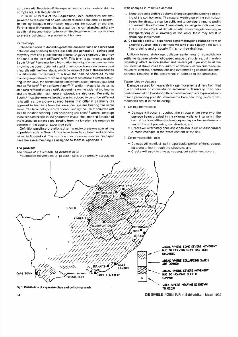
tributed throughout South Africa, as shown in Fig 1 Horizons with
potentially collapsible fabrics are commonly encountered across the
southern, south-western and central parts of the Transvaal, in the
Bloemfontein and Durban environsand in acorr idor in theorange Free
State north of Bloemfontein stretching to the Vaal River. Expansive
soils, on the other hand, are more widely distributed across South
Africaand have been reported tooccu r in most partsof thecountry with
the exception of the Little Karoo, the extreme northern Cape, the far
northern Transvaal and the extreme eastern Transvaal regions. The
areas most affected by expansive soils include the OFS gold fields, the
western Transvaal and the PWV complex, which are some of the most
densely populated areas in South Africa.
Pioneering work in identifying, establishing and predicting basic
parameters for expansive soils was undertaken by Jennings and
others fro m as early as 1947 . By the early 1960s practical structura l
procedures and techniques for building construction on these soil
horizons as well as a site classification system had been formulated
and successfully ~rnple mented, hich resulted in a table being com-
piled by Jennings and Kerrich2 relating structural solutions (building
practices) to a range of to tal estimated heave movements. At about the
same time, the phenomenon of collapsing soils was mvestigated by
Knight, who developed a theory explaining the mechanism of collapse
and a laboratory p rocedure for predicting collapse settlement3.
In the field of expansive clays, ongoing South African research has
made advances in pred icting the total and differential heave move-
ments that astructure may experience and the development of an ade-
quate design method for stiffening the foundations of residential
structures to tolerate these movements. On the other hand, no signifi-
cant research in to the field of structures founded on collapsible soils
has been undertaken since the early 1960s. To date, there is no South
African code of practice for the construction of structures founded on
prob lem soils, despite the obvious necessity for such acode. Neither is
there a uniform classification system nor a standardized approach to
build ing procedures for the range of problem soil horizons that may be
encountered in this country.
Existing legislation
The existing South African legislation makes provision for
1. The general investigat ion of soil conditions prlor to the establish-
ment of a township in some of the provinces (eg theTransvaal Town
Planning and Township Ordinance (Ordinance 15 of 1986)).
2 The submiss~on f plans for approval by the local author~ ty rlor to
the construction of structures on problem soil horizons (National
Building Regulations and Building
Standards Act (Act 103 of
1977)).
According to the National Build ing Fiegulations4 (NBR) the foun-
dations of all structures must comply with the functional requirements
contained in Regulation HI, namely The foundation of any building
shall be des igned to safely transmit all the loads from such building to
the ground. Empirical rules that are deemed to satisfy this regulation
are contained in SABS 04005. However, these empirical rules do not
apply to foundations supporting walls founded on heaving soils, shrink-
able clays or soils with a collapse fabnc, in wh ~c h ase the appolnt-
ment of a professional engineer to design such foundations In ac-
DIE SlVlELE INGENIEUR in Suid-Afrika Maar t 1992
8/11/2019 Foundation design on poor soil
http://slidepdf.com/reader/full/foundation-design-on-poor-soil 2/14
cordan cewi th Regula t ion B1 s requ i red ; s uch app o~ n t m e n tonst i tutes
wi th changes in mois ture content :
comp l iance wi th Regula tion H1
In terms of Part A of the Reg ulat ions, local authori t ies are em -
powered to requ i re that an app l i ca t ion to erec t a bu i ld ing be accom-
pan led by adequate in format ion regard ing the subso i l o f t he s i te .
Fur thermore, hey areen t i t l ed o presc r ibethe form at and ex tent o f any
add i t i ona l documentat ion to b e submi t ted together wi th an app l i ca t ion
to erec t a bu i ld ing on a pr ob le m so i l hor izon.
Terminology
The terms used to de sc r~ be eotechn ica l cond i t i ons and s t ruc tura l
so lut ions apper ta in ing to prob lem so i l s are genera l l y i l l -de f ined and
may vary f rom one pu b l i ca t ion to another . A go od exa mple o f t h i s may
be found in the term s t i f f ened ra f t6 . Th is te rm i s common ly use d in
S ou t h ~ f r i c a . o des c r i be a founda t i on t echn i que on ex pansi v e so i ls
~ nv o l v i nghe
construction
of a gr id o f re in force d conc re te beam s cas t
integral ly wi th the f loor s labs, which by v l r tue of thei r s t i f fness r educe s
the d i f fe rent ia l moveme nts to a level t ha t can b e to lera ted by the
masonry supers t ruc ture wi thout s ign i fi cant s t ruc tura l d i s t ress occur -
r i ng. I n t he US A , t he s am e f oun da t ~ on y s tem i s s om e t ~ m es es c r i bed
as a waf f le s labg O o r a s t i f fened m a t 12 whi ls t i n Aus t ra l~a he terms
s tandard ra f t and gr i l l age ra f tg , depe nding o n the wid th o f t he beam s
and the excavat ion techn ique e mploye d, are a lso used. Recent l y, i n
South A f r i ca , t he term waf f le s lab was in t roduce d to desc r ibe s t i ff ened
raf ts wi th n ar row c lose ly spaced beams that d i f f e r i n geome t ry (as
oppos ed t o f unc t i on ) f r om t he A m er i c an s y s t em bea r i ng t he s am e
nam e . T he t e rm i no l ogy IS f u r ther con fused by the use o f s t i f f ened ra f t
as a foun dat~ on echn iqu e on co l laps~ ng o i l s i tes3. where, a l though
there are s im i la r i ti es in the geo met r i c layout , t he in tended func t ion o f
t he f ounda t ion d~ f f e r s ons i de rab ly f r om t he f unc ti on ~ t s r eq u~ redo
perform in the case of expans ive soi ls .
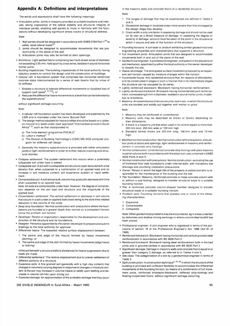
De f in i ti onsand ~ n t e rp re t a t i on s o fe rm s and ex p res s i ons ape r t a i n i ng
t o p rob l em s o i l s i n S ou th A f r~ c a av e been f o rm u l a ted and a re c on -
ta ined in Appe ndix A . The words a nd express ions used in th i s paper
have the same meaning as ass igned to them in Appen dix A .
The problem
T he na t u re o f m ov em en t s o n p rob l em s o i ls
Foundat ion mo veme nts on prob lem so i l s are normal l y assoc ia ted
1 Expans ive so i ls undergo vo lume chang es upon the wett ing and dry -
ing o f t he so i l h or i zons . The natura l wet t ing up o f t he so i l hor i zon
be low the s t ruc ture may b e suf fi c ien t to deve lop a m oun d pro f i l e
undern eath the s t ruc ture . A l te rnat ive ly, a change In mols ture con-
tent due to the e f fec ts o f c l imat i c cond i t i ons and vegeta t ion (evapo-
t ransportat ion) or a lowering of the water table may resul t In
shrmkage movements .
2 . Co l laps ib leso il s w i l l exper ien ceset t leme nt upon satura t ion f rom an
externa l source. This set t lemen t wi ll take p lace rapidly i f the soil is
f ree-dra ining a nd grad ual ly i f i t is not free-dra ining.
Uni form heave, shr inkage, co l lapse set t lements or conso l ida t ion
set t lements genera l ly do not cause dam age to s t ruc tures , but may det -
r imenta l l y a f fec t serv ice (water and sewerage) p lp e ent r~e s t t he
per imeter o f s t ruc tures . Non-un i form or d i f f e rent ia l movem ents cause
s t ruc tura l d i s t ress , deformat ion s and overs t ress ing o f s t ruc tura l com-
ponents , resu l t ing in the occu r rence o f da mage to the s t ruc tures .
Tendenc ies in damage
Dam age caused by heave/shr inkage movements d i f f e rs f rom that
due to col lapse or consol idat ion set t lements . General ly , i f no pre-
caut ions are taken to reduce d i f f e rent ia l movements or to prevent con-
di t ions promoting potent ia l movements f rom occur r ing , such m ove-
rnents wi ll re sul t in the fol lowing:
1 On expansive soi ls :
Damage wi l l occur throughout the s t ructure, the severi ty of the
dama ge be ing greates t i n the ex terna l wa l ls , o r i n terna ll y in the
cent ra l por t ions o f t he s t ruc ture , depending on the mois ture con-
tent o f t he so il p rec ed ing cons t ruc t ion ; an d
Crack s wi l l a l ternately ope n and c lose as a resul t of seasonal and
c l imat ic changes in the water content of the soi l .
2 . O n com pre ss~b le o i ls :
Dam age w~ l l an i fes t ~ t s e l fn a par t~cu la r or t lon o f t he s t ruc ture ,
eg a long a l i ne through the s t ruc ture ; and
Cracks wi l l open in t ime as subsequent se t t l ement occurs
Fig
:
istribution of expansive clays and collapsing sands
SITES WHERE HE VING
IS
KNOWN
TO OCCUR
84
DIE S lV lELE INGENIEUR in Su id -A f r~ ka Maar t 1992
8/11/2019 Foundation design on poor soil
http://slidepdf.com/reader/full/foundation-design-on-poor-soil 3/14
3.
On col laps ib le sol ls :
Damage wi ll be conf ined to p or t ions o f t he s t ruc ture as and when
co l lapse set t lement occurs , eg beneath foun dat ions ad jacent to
leak ing p lpes or ad jacent to areas o f poor dra inage where pond-
~ n gf rainfal l occurs .
Typ ica l ranges o f cos ts o f remedia l work requ i red to rehab i l i ta te
s t ruc tures that were bu i l t w i thout p recaut ions on norm al s t r ip foot ings
are given in Table 113.
Prevent ion versus repair
Notwi ths tand ing the fac t t ha t the NBR conta in m anda tory requ i re-
ments for the des ign o f f oundat ions on p rob lem so i ls , t he ques t ion
ar i ses as to whether or not prevent ion o f c rack lng i s pre ferab le to
remedia l measures. In a t tem pt ing to answer th i s ques t ion, the fo l low-
ing fac tors shou ld be taken in to account :
1 . The cost o f repa i r o r abno rmal main tenance cos ts (see Tab le 1 for
order of magni tudes).
2. The ini t ia l con struc t ion cost ' . l (see Tab le 2 for est imates).
3 The impac t o f s t ruc tura l damage on the resa le va lue o f t he
st ructure.
4 The cost of inconvenience associated wi th repa i rs .
5. Emo t ional ef fects .
6.
Englne ering factors such as s tabi l i ty , safety and s t ructural in-
tegrity.
7 . Env i ronmenta l f ac tors such as whether or not the s t ruc ture i s
habitable.
8 The r isk of the predic te d potential move men t be lng rea l ized.
I r respec t ive o f whether or n ot ~ t s mo re economical t o a llow damage
than to prevent damage , the leg is la tors have determ ined that preven-
t ion i s requ i red. I t wou ld appear f r om Regula t ion B1 o f t he NBR that the
in tent ion o f t he law-makers i s to address the above-ment ioned
engineer ing and env i ronmen ta l ac tors wi th , perhaps , theem phas is on
stabi l ity a nd safety .
Shor t com ings ~n the ex is t ing leg is la t ion an d admin is t ra t ion pro -
c edu res
A l though loca l author i t ies , i n erm sof the NBR, areap poin ted toc on-
t ro l and to approv e the erec t ion o f s t ruc tures o n a l l so i l hor i zons , they
se ldom exerc ise the i r powe rs to ca l l f o r f oundat ion re por t s and to
enforce the NBR desp i te the i r knowle dge o f the presence o f prob lem
soi l hor i zons in par t i cu lar areas under the i r cont ro l . The genera l
approach o f mos t loca l author i t i es i s to d is tance themselves f rom
invo lvement in s t ruc tures fou nded on p rob lem so i ls . The onus o f
detec t ing such hor i zons and com pl iance wi th the regu la t ions i s p laced
on the owner a nd the su i tab i li t y of t he cons t ruc t ion so lu t ions on a p ro-
fess iona l eng ineer appo in ted by the owner . A l te rnat i ve ly , a loca l
author i t y may approve a p lan for the cons t ruc t ion o f a s t ruc ture that i s
t o be ounded on a p rob l em s o il ho r iz on , p rov i ded theowne r ge t s a p ro -
fessiona l eng ineer to s lgn ' fo r t he s t ruc ture . Deta l ls o f any des lgn pro -
posa ls are rare ly ca l led for or
examined.
The wisdom of th i s approa ch i s ques t ionab le . Rep or t s abound in the
news media o f t ownsh ips and hous ing schem es cons t ruc ted wi thout
any , or w i th inappropr ia te , precaut ions hav ing been taken aga ins t
ground movement , now suf fer ing the inev i tab le consequences o f
ex tens ive c rack ing and s t ruc tura l d i s t ress . F requent l y , where the s ta te
or local government is involved, these pro blems becom e pol i t ic ized.
The record o f t he co nduc t o f p ro fess iona l eng ineers in th i s f ie ld o f
eng ineering i s fa r f rom be ing above re proach . An examinat ion o f t he
South A f r i can C ounc i l f o r P ro fess iona l Eng ineers ' (SACPE) annual
reports over the past few years indicates that the major i ty of the dis-
c ip li nary e nqu i r ies in to des ign inadequac ies re la ted to foundat ion
des ign on uns tab le an d expans ive so i l s. I n the 1986-1987 annual
repor t , t he Counc i l recorded the fo l lowing when rep or t ing on the Code
of Profess ional Conduct and contravent ions of the Act : 'A number of
compla in ts invo lved the unde rdes ign o f f oundat ions in areas o f expan-
s ive so il s . Counc i l i s concerned that pro fess iona l eng ineers tend to
underest imate the level of expert ise req uire d. ' In i ts Newslet ter N o
4
(Ju ly 1989) SACPE at temp ted to addre ss th i s i ssue by br ing ing to the
at tent ion of profess ional engineers the fact that the 'des ign of foun-
dat ions in areas of expa ns ive so i ls is a mat ter wh ich requ i res spec ia l
ex pe r ti se ' and by u rg i ng p ro fes s iona l eng i nee rs t o a c ~ u i r e he
Table 1: Typical repair costs of masonry single-storey residential structures
founded on problem soils with normal construction and no pre-
cautions
Site class Dffferen tial
(See Table 3 movement
Type of
movement
Shrinkage1
heave
Settlement
Approxfmate range of eshmats
repair cost*
( of present-day new house
construction cost)
On sltes
subject
to
collapse settlement
thls
f ~ g u r e o u ld
r r p r e s e n t the repal r
cost to
repa l r
one
localved area
of collapse
settlement
Table
2:
Typical initial costs of s tructural solutions for single-storey residential
masonry structures founded on problem soils
Site class
l Differen tial Type of
(See Table
3
movement
I
movement
C , H. R and
S
<2 , 5
I
C1 and S1 2.5 7.5 Settlement
C2 and S2
>T
H1
H2
H2 and H3
H 2 a n d H 3
Construchon
type
Normal constructlon
[inte rna l walls foundec
on strip footings)
2.5 7.5
7,5
15
> l
> l 5
Estimated
addftional
CO
(
of
inftfal
house con-
structfon cos
O
Heave/
shrinkage
Modified normal
Split constructlon
St~ffenedaft
Piled constructlon
Modified normal 1 3
Piled or pler 5 1Soo
:onstruction
Stiffened strip foot~ngs
3r stiffened ra ft
5 10
necessary capa b l l l t ~es ' o under take such des ign w ork , l e by keep ing
up oda t ew i t h m ode rn ec hno log i c al adv anc es s o as t oens u re an ade -
quate and economlc des ign. '
Des ign inadequacies are exacerbated by the fact that no des lgn
s tandards or co des o f prac t i ce ex ist ~nSouth A f r i ca for the des ign and
cons t ruc t ion o f s t ruc tures on p rob lem so l ls . Th ls
shortcoming
engen-
ders er ron eous expec ta t ions of s t ruc tura l per formance and m lsun-
ders tand ings between owner and professional engineer ; f u r thermore
serv iceab i li t y s tandard s tend to be owered in he pursu i t of a reduc t ion
In ini t ia l construct ion costs by developers.
ddressmg the problem
A
hypothes is
Observations
of repo rted fal lures In res ldent lal masonry s t ructures
founde d on prob lem so l l s In non-do loml t l c areas have led to thefo llow-
Ing hypothes ls P rov lded that a reasonably
appropriate
cons t ruc t lon
so lu t lon IS adopted s lgn l fl cant dama ge will not occur
I f thls hypothes ls IS ado pted as the bas ls for des lgn a system of
c lasses of s ltes serv lceab l l l ty cr l ter la and accepta ble construct lon
prac t l ce IS r equ l red t o de f lne and I n te rp ret t he t e rm s app ro p r~ a t e on -
s t ruc tlon so lu t ions an d s lgn i f lcant dam age
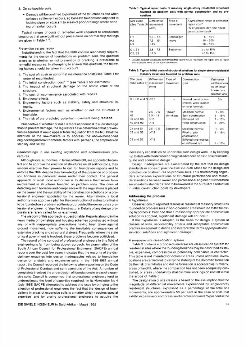
A pro po sed s i te c lass if i ca tion sys tem
Table
3
conta ins a propo sed universal slte classif ication system for
residential s i tes where the found ing hor i zons may be described as sta-
ble, expans ive, compress ible or potent ial ly col laps ible in character.
Th is tab le IS not intended for dolomit ic areas unless addi t ional inves-
t igat lons are carr ie d out to veri fy the s tabi l i ty of the dolomlt ic for mat ion
(ie the r lsk of s inkholes a nd dol in e format ion is accep table). S imi lar ly ,
areas o f l andf i ll , where the com pac t ion h as not been adequate ly co n-
t ro l led , or areas under la in b y sha l low mine work ings do n ot fal l w i th in
the scope o f Tab le
3
The des ign at ion of s i te c lasses is based on the assum pt ion that the
magn i tude o f d if f e rent ia l movements exper ienced by single-storey
res ident ial s t ructures, expressed as a percentage of the total soi l
movements , are approx imate ly
50
per cent in the case of soi ls that
exh ib i t expans ive or com press ive charac ter i s t ics and 75 per cent in he
DIE SlVlELE INGENIEUR in Suid-Afr ika Ma art 1992
8/11/2019 Foundation design on poor soil
http://slidepdf.com/reader/full/foundation-design-on-poor-soil 4/14
Fine-grained solls
with moderate to
very hlgh plastic~ty
(clays, silty clays,
clayey s~l ts nd
sandy clays)
Table
3:
Residential site class designations
Silty sands, sands, Compressible
sandy and gravelly and potent~ally
soils collapsible soils
Fine-grained so~ls Compressible
(clayey silts and soils
clayey sands of
low plasticity),
sands, sandy and
gravelly soils
Typical founding
material
Rock (excluding mud
rocks that
exhib~t welling
to some depth)
case of soils that exhibit both compressive and collapse characteris-
tics. Where this assumption is incor rect or inappropriate , the site class
should be determined on the basis of the resultant differential move-
ment read from the table being equal to that expected in the field.
In some instances, it may be more appropriate to use a composite
designation to describe a site more fully, eg Cl /H 2 or S1 and/or H2.
Composite site classes may lead to higher differential movements and
result in design solutions appropriate to a higher range of differential
movement, eg a class RIS1 site may be described as a class S2 site.
Alternatively, a further site investigation may be necessary, as the final
design solution may depend on the location of the structure on a par-
ticular site with variable soil conditions.
Proposed serviceability criteria
The NBR (see Regulation Bl (1 ) of Part B) prescribe that 'any build-
Ing and any structural element or component thereof shall bedes igned
to provide strength, stability, serviceability and durability, in accor-
dance with accepted principles of structu ral design
.'
The 'deemed-
to-satisfy rulescontained in SABS 0400donotcontain any guidanceor
definitions of acceptable serviceability and durability criteria; they
merely refer the reader to the South African codes of practice or struc-
tural design.
The South African codes of practice, on the other hand, offer com-
prehensivegu idance on assessing thestrength, stability and structural
integrity of structures and, with the exception of the masonry code,
offer some useful guidelines, based on allowable deflection ratios, to
restrict deformations, distortions and structural distress arising from
applied loads to within acceptable lim its. SABS 0160q5 General pro -
cedures and oadings to be adop ted for the design of buildings) states,
in subclause 3.1.3, that 'the deforma t~on f a building or any part of it
should not adversely affect the appearance or proper function ing of the
building'. In SABS 0161' (The design of foundations for buildings), in
regard to ground movements that are independent of the applied load
(see subclause 5.1.2). ~t s stated that 'the designer should decide, hav-
ing regard to the user's requirements and the design of the building,
whether the effects of such movements can be tolerated'. Apart from
these two general references to serviceability considerations, the
structural codes are silent on serviceability criteria relating to, or that
may be adopted for, residential structures founded on problem soil
horizons.
Burland et all on the other hand, have suggested that there are
three basic criteria that ought to be satisfied when limiting movements
are considered, viz:
Character of
founding materfal
(mm)
Stable
1. Visual appearance
2. Serviceability or function
3. Stability
Experience has shown that deviations from the vertical or horizontal
in excessof l/ 25 0 and local slopes in floors in excessof l /lO Oar e likely
to be noticed and will often cause subjective feelings that are unplea-
sant and possibly alarmingt6.Excessive movementscan also affect the
function of a struc ture by causing service pipes to fracture and win-
dows and doors to jam. Crac k~ng f the masonry itself, rom an owner's
poin t of view, is generally aesthetically unacceptable and of great
concern.
The attainment of a completely crack-free masonry structure, on the
other hand, even on the most stablesoil horizon, isvirtually imposs~ble.
Masonry is a b rittle construction material and as such is susceptible to
cracking. In addition to foundation movements, cracking in residential
structures may arise from one or a combination of the following1':
1 .
Thermal movements (expansion and contraction).
2. Moisture movements in masonry units (wetting and drying, and
shrinkage in concrete and calcium silicate units).
3. The absorption of water vapour on a molecular level In burnt clay
units (moisture expansion).
4. Corrosion of wall ties and brick reinforcement .
5. High-strength morta rs rich in cement.
6. Structural overload.
7.
Shrinkage of concrete roof or floor slabs.
8. Deflection of the supporting structure under load.
In residential structures:
1. Thecauses of cracking in masonry are not always related to applied
loads or displacements.
2. Excessive deflections are unlikely to occur from applied lateral
loads such as wind.
3. Deflections and distor tions in walls leading to the fracturing of ser-
vice pipes and the jamming of windows and doors will occur only
after cracking has taken place in the masonry.
4. The structural codes of practice offer no quantifiable guidance on
serviceability criteria .
It would therefore be useful to formulate performance-oriented ser-
viceability criteria in order to classify ranges or degrees of damage to
which a structure may be subjected.
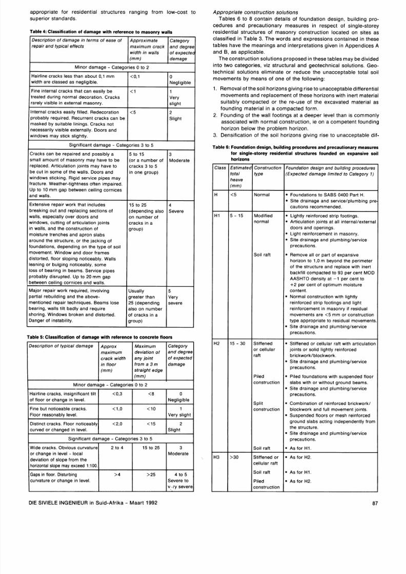
A proposed performance-oriented classification system describ-
ing the level of damage with respect to walls and floors is contained in
Table (masonry walls) and in Table 5 (concretefloo rs). Table4, which
classifies the degree of damage in terms of ease of repa ir, crack width.
impairment of function and visible (aesthetically unacceptable)
damage, is based on the work of Jennings and Kerrich2,Burland et all6
and G i ~ e s ' ~ . ' ~ a n dn the Australian Standard AS 28 70~. able 5, on the
other hand, is similar to a table contained in AS 2870.
Tables and 5 are divided into two degrees of damage, namely
minor damage and significant damage. Minor damage describes vis-
ible damage relating to relatively isolated, narrow cracks that can
generally be repaired when redecoration of the wall finishes is under-
taken and distortionsin thewallsand w~ndow sthat re notobviousand,
at worst, only cause doors and windows to stick slightly. Significant
damage, on the other hand, describes damage relating to wide cracks
or groups of narrow cracks that can generally be effectively repaired
only by rebuilding portions of the walls, effecting improvements to the
foundations and/or cutting articulation joints mto the walls, and to
not~ceable istortions in the walls and floors causing doors to jam, ser-
vice pipes to fracture and floor finishes to crack or tear1'.
It must be stressed, however, that in assessing the category of
expected damage, account must be taken of the locat~onn the struc-
ture of the damage, and of the function of the structure. Likewise, the
width of cracks should not be seen in isolation when the category of
expected damage is decided upon; it is only one factor and should not
be used by itself in classifying damaget6.
In terms of Regula tion B1 of the NBR, categories of expected
damage with a valueequal to or greater than four are considered t o fall
outside the perm issible strength and stability limits, whilst those with a
value equa l to or greater than three are considered to fall short of the
serviceability and durability requirements of the regulations, when
read as a whole.
It is therefore proposed that significant damage (category 3 and
higher) should not be permitted. Categories of minor damage would
then constitute a range of performance-oriented serviceability criteria
Expected
range of total
movements
at surface
of soil
Negligible
DIE SlVlELE INGENIEUR in Suid-Afrika Maart 1992
Assumed
different~al
movement
(
of total)
Site
class
R
8/11/2019 Foundation design on poor soil
http://slidepdf.com/reader/full/foundation-design-on-poor-soil 5/14
appropriate for res ident ial s tructures rangi ng from low-cost to
Appropr ia te cons t ruc t ion so lut ions
Tables
6
t o 8 conta in deta i ls o f foundat ion des ign, bu i ld ing pro-
cedures and precautionary measures m respect of s ingle-storey
res ident ial s tructures of masonr y construct ion located o n s ites as
c lass if ied in Table
3.
The words and express ions conta ined in these
tables have the meanings and in terpretat ions g iven in Appendices A
and B as appl icable.
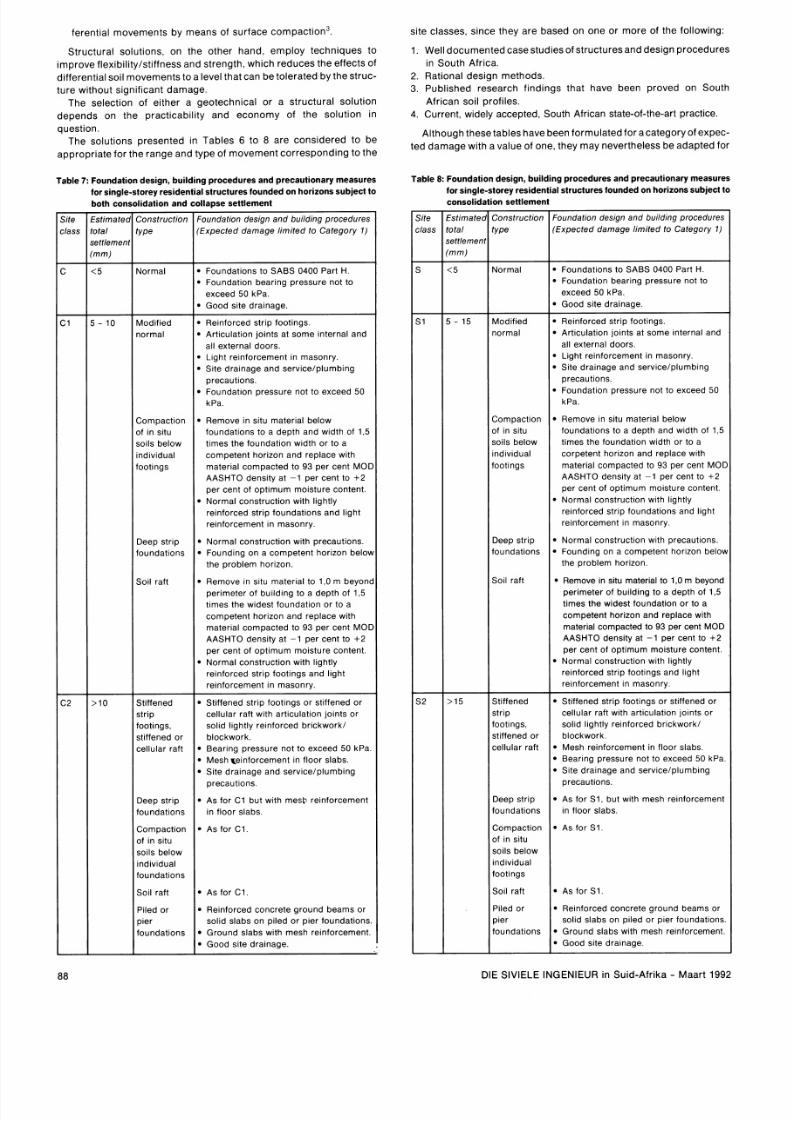
The cons t ruc t ion so lut ions propose d n hese tab les may be d ivided
into two categories, v iz s tructural an d geotechnical solut ions. Geo-
technical solut ions el iminate or reduce th e unacceptable total soi l
movements b y means of on e of the fo l low ing:
1 Removal of the soi l hor izons giv ing r ise to unacceptable dif ferent ial
movemen ts and rep la cement of these hor izons w i th iner t mater ia l
suitably compacte d or t he re-use of the excavated mater ial as
founding mater ia l in
a
compac ted form.
2. Found ing of the wall foot ings at a deeper level than IS commonly
associated w i th no rmal cons t ruc t ion, ie on a competent founding
hor izon be low the proble m hor izon.
3. Densif icat lon of the soi l hor izons giv ing r ise to unacceptable dif-
Table 6: Foundation design, build ing procedures and precautionary measures
for single-storey residential structures founded o n expansive soil
superior s tandards
Table : Classification of damage w ith refe rence to masonry walls
Approximate
maximum crack
width in walls
(mm)
Category
an d degrs
of expects
damage
Description of damage in terms of ease of
repair and typical effects
Minor damage -
Categories
0 o 2
horizons
Hairline cracks less than about
0,l
mm
width are classed as negl ig~bl e.
Fine internal cracks that can easily be
treated dur ~n g ormal decoration. Cracks
rarely visible in external masonry.
Internal cracks easily filled. Redecoration
probably required. Recurrent cracks can be
masked by su~tableinings. Cracks not
necessarily visible externally. Doors and
windows may stick slightly.
stimate
otal
leave
mm)
Construction
type
<0,1
<
<5
Foundat~on esign and building procedures
(Expected damage limit ed to Category 1)
0
Negligible
Very
slight
2
Slight
Significant damage Categories 3 to 5
Normal
Cracks can be repaired an d possibly a
small amount of masonry may have to be
replaced. Art~culationo~ntsmay have to
be cut in some of the walls. Doors and
wmdows sticking. R ig ~d ervice pipes may
fracture. Weather-tightness often Impaired.
Up to 10 mm gap between ceiling cornices
and walls.
Foundations
to SABS 0400 Part H.
Site drainage and serwce/plumbing prc
cautions recommended.
xtensive repair work that includes
breakmg out and replacing sectlons of
walls, especially over doors and
wmdows, cuttlng of
articulation
joints
in walls, and the construction of
moisture trenches and apron slabs
around the structure, or the jack~ng f
foundations, depending on the type of soil
movement. Window and door frames
distorted,
floor sloping noticeably. Walls
lean~ ng r bulging
noticeably,
some
loss of bearing in beams. Service pipes
probably disrupted. Up to
20
mm gap
between ce~l ino ornices and walls.
5 o 15
(or a number of
cracks 3 to
5
in one group)
l5
to
25
(depending also
on number of
cracks In a
group)
3
Moderate
4
Severe
Modified
normal
Soil raft
Lightly reinforced strip footings.
Articulation joints at all internallexterna
doors and openings
Light reinforcement in masonry.
Site drainage and plumb~ng/service
precautlons
Remove all or part of expansive
hor~zono 1,Om beyond the perimeter
of the structure and replace with inert
backfill compacted to 93 per cent MOD
AASHTO density at 1 per cent to
2 per cent of optimum moisture
content.
Normal construction w~th~ghtly
reinforced strlp footmgs and hght
reinforcement in masonry ~f esidual
movements are <5 mm or construction
type approprlate to residual movements
Site drainage and plumb~ng/service
precautlons.
Major repair work required, involving
Usually
partial rebuildmg and the above-
greater than
mentioned repair techniques. Beams lose
25 (depending
bearing, walls tilt badly and require
also on number
shoring. Windows broken and distorted.
of cracks in a
Danger of ~nstability. group)
Very
severe
Table 5: Classification of damage with reference to concrete floors
Stiffened
or cellular
raft
Piled
construction
Split
construction
So11 aft
Stiffened or cellular raft with articulation
joints or sohd lightly reinforced
brickwork/blockwork
Site drainage and plumbing/service
precautlons.
Piled foundations with suspended floor
slabs wlth or without ground beams.
Site drainage and plumbing/service
precautions.
Combmation of reinforced brickwork/
blockwork and full movement joints.
Suspended floors or mesh
reinforced
ground slabs acting independently from
the structure.
Site drainage and plumbing/service
precautions.
As for HI.
Description of typical damage
Stiffened or
cellular raft
Soil raft
P~ led
construction
Significant damage - Categories 3 to
5
As for
H2.
As for HI.
As for
H2.
~ p p r o x
maximum
crack width
in floor
(mm)
Wide cracks. Obvlous curvature
or change in level local
deviation of slope from the
horizontal slope may exceed
1.100.
Gaps in floor. Disturbing
curvature or change In level.
DIE SlVlELE INGENIEUR in Suid-Afr ika Maart
1992
Mmor damage - Categories 0 o 2
Maximum
deviation of
any joint
from a
3
m
straight edge
(mm)
Hairline cracks, insignificant tilt
of floor or change In level.
Fine but noticeable cracks.
Floor reasonably level.
Distinct cracks. Floor noticeably
curved or changed in level.
2
o
4
>
Category
and degree
of expected
damage
<0,3
<1,0
<2,0
15
o
25
>25
Moderate
o 5
Severe to
v -ry severe
<
<l0
<l5
0
Negligible
Very sllght
2
Slight
8/11/2019 Foundation design on poor soil
http://slidepdf.com/reader/full/foundation-design-on-poor-soil 6/14
ferent ial movements by means of surface compaction
site c lasses, s ince they are based on on e or mor e of the fol lowing:
Structural solut ions, on the other han d, employ techniques to
improve f lex ibi l i ty /s t~ffness n d strength, which redu ces the effects of
1. Well docume nted casestudie sof s tructuresan d design procedures
in South Afr ica.
2.
Rational design methods.
3. Published research f indings that have been proved on South
African so11profiles.
4 Current, w~d el y ccepted, South African state-of-the-art practice.
dif ferent ial soi l movements o a level that can be olerated by hestru c-
ture without s ignificant damage .
The select ion of either a geotechnical or a s tructural solut ion
depen ds on the pract icabi l i ty an d economy of the solut ion in
question.
The solut ions presented in Tables
6
t o
8
are cons idered to be
appropria te for the range and type of movement cor responding to the
Although these ables have been ormulated for acategory of expec-
ted d amage with a value of one, they ma y nevertheless be adapted for
Table
8:
Foundation design, building procedures and precautionary measures
for single-storey residential structures founded on horizons subject to
Table 7: Foundation design, build ing procedu res and precautionary measures
for single-storey residenti al structures founded on horizons subject to
both consolidatio n and collapse settlement
consolidation settlement
/te
lass
istima ec
otai
:ettiemen
mm)
lite
lass
;
1
;2
:stlmatec
otal
ettlemen
mm)
15
Construction
type
Normal
Modified
normal
Compaction
of In s~tu
soils below
~ndlv~dual
foot~ngs
Deep strip
foundat~ons
So11 aft
St~ffened
strlp
foot~ngs.
stiffened or
cellular raft
Deep strlp
foundations
Compact~on
of In sltu
soils below
tnd~v~dual
footlngs
So11 aft
P~led r
pler
foundat~ons
E d a t l o n design and building procedures
(Expected damage lim ited to Category 1)
Foundat~on esign and build~ng rocedures
(Expected damage limited to Category l )
Foundat~onso SABS 0400 Part H
Foundat~on earing pressure not to
exceed 50 kPa.
Good site drainage.
Normal
Foundat~onso SABS 0400 Part H.
Foundatlon bear ~ng ressure not to
exceed 50 kPa.
Good site drainage.
Retnforced strlp footlngs
Arttculat~onotnts at some Internal and
all external doors
Llght relnforcement In masonry
Stte dralnage and servtcelplumb~ng
precautlons
Foundat~on ressure not to exceed 50
k Pa
Modlf~ed
normal
Compaction
of In sltu
so~ls elow
~ndtv~dual
foot~ngs
Deep strip
foundatlons
Sod raft
Remforced strlp footlngs
Arttcu lat~o n olnts at some Internal and
all external doors
Light re~nforcement n masonry
Stte dralnage and se rv~celp lumb~ ng
precautlons
Foundat~on ressure not to exceed 50
kPa
Remove In s~ tumater~al elow
foundat~ons o a depth and w~ dt h f
1
5
times the foundat~on ldth or to a
competent hor ~zon nd replace wlth
mater~ al ompacted to 93 per cent MO[
AASHTO den s~ty t
1
per cent to 2
per cent of optlmum molsture content
Normal constructlon w~thtghtly
re~nf orced trlp foundat~onsand hght
relnforcement In masonry
Normal constructlon wlth precautlons
Found ~ng n a competent ho r~zo n elob
the problem hor~zon
Remove In s~tumatertal to 1 0 m beyon,
perimeter of butldlng to a depth of 1 5
ttrnes the w~d est ounda t~on r to a
competent hor~zo n nd replace w~th
mater~ al ompacted to 93 per cent MO[
AASHTO den s~ty t
1
per cent to 2
per cent of optlmum motsture content
Normal constructlon wtth l ~ghtl y
re~nf orced trlp footlngs and llght
re~nforcement n masonry
Remove In s~tumater~ al elow
foundatlons to a depth and wldth of 1 5
tlmes the foundatton wldth or to a
corpetent horlzon and replace w~ th
materlal compacted to 93 per cent MO1
AASHTO de ns~ty t
1
per cent to 2
per cent of optlmum molsture content
Normal constructlon w~ th ghtly
re~nf orced trip foundat~ons nd light
relnforcement In masonry
Normal constructlon w~ th recautlons.
Founding on a competent h or~zo n elo\
the problem horizon.
Remove In sltu materlal to 1,O m beyond
perimeter of bulldmg to a depth of 1,5
tlmes the w~destoundatton or to a
competent h or~zon nd replace w~th
mater~al ompacted to 93 per cent MOO
AASHTO denslty at 1 per cent to
+2
per cent of optlmum molsture content
Normal constructlon w~th~ghtly
re~nforced trp foot~ngs nd hght
relnforcement In masonry
St~ffened trlp footlngs or st~f fene d r
cellular raft wlth arttculatlon Iolnts or
solid lightly re~nforced r~ckwor kl
blockwork
Mesh relnforcement In floor slabs
Bearmg pressure not to exceed 50 kPa
S~te ra~nage nd serv~celplumb~ng
precautlons
As for S1 but w~ thmesh re~nforceme ni
In floor slabs
As for S1
St~ffened
strlp
footlngs,
stiffened or
cellular raft
Deep strlp
foundations
Cornpactlon
of In s~t u
so~ls elow
~ n d ~ v ~ d u a l
foundat~ons
So11 aft
Piled or
pier
foundations
Stiffened strlp fo ot~ng s r stiffened or
cellular raft wlth arttculatton Iolnts or
solid Itghtly reinforced br tckwork l
blockwork.
Bearing pressure not to exceed 50 kPa
Mesh qe~nforceme ntn floor slabs.
Site dra~na ge nd service/plumbing
precautlons
As for
C1
but with mesh relnforcement
In floor slabs.
As for C1
As for C l .
Retnforced concrete ground beams or
solid slabs on p~ le d r pier foundations
Ground slabs with mesh re~nforcement
Good site drainage.
As for S1
Remforced concrete ground beams or
solid slabs on p~ le d r pler foundat~ons
Ground slabs with mesh re~nforcement
Good slte drainage.
DIE SlVlELE INGENIEUR in Suid-Afr ika Maart
1992
8/11/2019 Foundation design on poor soil
http://slidepdf.com/reader/full/foundation-design-on-poor-soil 7/14
category 2 l evels o f expec ted dama ge wi th some m inor modifications.
An Inc rease in the degree o f da mag e p ermi t ted im pl ies that the s t ruc -
tures in ques t ion wil l be pr ov ~d ed l t h less s ti ff f oundat ions or less f lex -
~ b l eupers t ruc tures . Thus the cons t ruc tlon d eta l l s as opposed to the
construct lon type) wi l l change. Accordm gly , the am ount of s teel rein-
forcement In both the m asonry and foundat ions re fer red to in these
tab les may be e i ther reduc ed or omi t ted. In the case o f sp l i t cons t ruc -
t lon . t he l lm i t o f d~ f fere nt la l eave that may b e to lera ted may b e ra ised
to 40 mm , whi l s t i n modi f ied norm al cons t ruc t ion the numb er o f
art lculat lon jolnts may be reduced
I m p l em en t i ng a s y s t em a t i c app roac h t o des i gn a nd c ons t ruc t i on
Class i f icat ion of erven
At the outset o f a townsh ip deve lopment pro jec t , a geotechn lca l
inves t igat ion com pr is ing a s tab i l~ t ynves t lgat lon of t he s i te i f unde r lam
by do lomi tes ) and an investigation i n to the foundat ion charac ter i st i cs
of the near -sur face so i l hor izons i s requ i re d:
1. As a p lann ing a id In the determinat ion o f app ropr ia te land use.
2.
To en ab le the loca l author i t y to assess the suitability o f t he s ~ t eor
the proposed deve lopment .
3. To prov id ethe oca l author i t y w i th information i n o r d e r t o e n a b l e i t t o
enforce the requ i re ments o f t he NBR.
4 .
To prov ide a prospec t i ve deve loper or owner wi th in format ion
regard ing found ing cond i t i ons .
T h ~ snves t igat ion shou ld cu lm ina te in the pre parat ion o f a so i l map
~ n d ~ c a t l n goun dar ~es f a reas wi th comm on s i te c lasses des ignated in
accordance wi th Tab le
3,
t ogether wi th a repor t conta in ing the
fol lowing:
1.
A desc r ip tion o f the s ite , ~ t socat ion and the nature o f t he in -
vestigation.
2.
Deta il s o f the s i te geo logy and en g lneer lng prope r t ies o f the found-
Ing hor i zons .
3. A geotechn ica l eva luat ion of f ound ing con d i t~o ns ,nc lud ing recom -
m enda t i ons on f ound i ng dep t hs.
4 .
Deta il s of any pro b lem s tha t may have been ident i fi ed and that may
have a bearing o n the des ign and construct ion of the s t ructures.
5.
Ful l part iculars of al l boreholes, t r ia l holes and test pi ts and the
resul ts of al l f le ld and laboratory tests .
A f ter the town sh ip layout has been f ina l ized an d thee rven have been
physically
pegged. but be fore cons truc t ion o f t he s t ructures comm en-
ces , a fu r ther inves t igat ion i s p ropose d to es tab l i sh the s i te c lass in re-
s pect o f eac h m d l v idua l e r f. T h ~ s dd~ t l ona l oun da t ~ on nves t igat ion
would b e a imed a t conf i rm ing and am ending , as necessary , the pre -
v ious ly determined boundar ies o f areas wl th common s i te c lasses .
General ly , this invest igat ion wi l l no t necessari ly entai l addi t ional tes t ing
and m ay requ l re no m ore han t he excavation of tes t p l t s to conf i rm the
p r e v ~ o u s l ydent i f ied pro f i l es and s i te c lass bound ar ies . Aga in , t h i s
inves t igat ion sh ou ld cu lm inate in a repor t conta in ing any add i t i ona l
pertinent l n format lon and a so i l m ap by m eans o f wh lch the s l te c lass
designation
f o r eac h ~ nd l v l d ua l r f m ay be ascertained.
The two above-ment ioned repor t s , t ogether wi th the s i te c lass
des ignat ions for each er f , shou ld b e submi t ted to the bu i ld ing inspec -
torate of the appl icable local authori ty in order to enable i t to:
1 Sys temat i ca l l y cont ro l t he erec t~on of s t ruc tures on prob lem
soils.
2
Furn ish in teres ted par t ies wi th comprehens ive geotechn ica l i n -
format ion.
3. Cont ro l t he rec lass i fi ca t ion o f any ind iv idua l s i t es th i s may be
requ i red in the case o f erven s i tuated on the border o f two
zones).
Where undeve loped s tands in ex is t ing townsh ips are to be de-
ve loped and so i l maps are not ava i lable , e~ th erhe loca l author i ty , t he
developer or the owner would be requ i red to appo in t a p ro fess iona l
englneer to des ignate the s i te c lass in terms of Table 3
Cont rol l ing the des ign a nd co ns t ruc t ion o f s t ruc tures
The bul ldlng inspectorate of the local authori ty has s tatuatory
author it y to mo n~ tor nd con t ro l the erec t ion o f s t ruc tures . I n order to
fac i l i tate this funct ion, however, i t is cons idered important that a
manual be made ava i lab le to the inspec tora te set ting out ax ep ta b l e
s tandards and o ther re qu i rem ents apper ta in ing to the des ign and con-
s t ruc t ion o f f oundat ions and s t ruc tures on prob lem so i l s . Such a
m anua l wou l d p rov ide :
1
A c l a s s ~ f ~ c a t ~ o nrocedure for the determlnat lon of s l te c lasses,
gu ldan ce on ra t lona l des lgn concepts and acceptab le serv lceab l ll ty
l ~ m l t s
2 Standard deta l l s In respec t o f p lu mb ~n g erv lces and dramage see
Appe ndlx B ) , a r tl cu la t lon joints joints associated wlth spht con-
s t ruct lon and sets of rules
governing
the s tabl l l ty of certam
jointed wal ls
3 Maintenance and pe r forman ce ln format lon for use by owners
4 Procedures for the sub mls s~o n f p lans for approva l by the loca l
authority
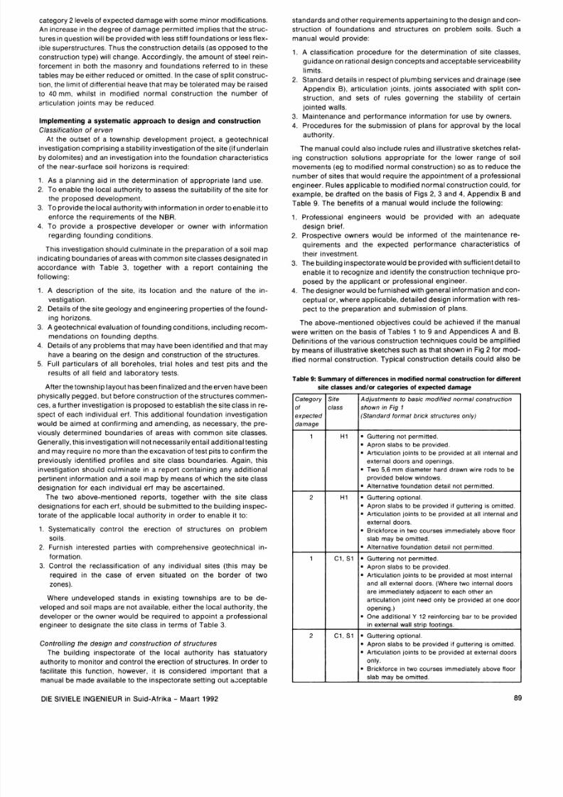
The manu al cou ld a lso Inc lude ru les and i ll us tra t ive sketches re la t-
ing cons t ruc t ion so lu t ions appropr ia te for the lower range o f so i l
move ments eg to mod i f ied normal cons t ruc tion) so as to reduce the
numb er o f s i tes that wou ld requ i re the appo in tment o f a pro fess iona l
eng ineer . Ru les app l i cab le to m odi f ied norm al cons t ruc tion cou ld , f o r
example , be dra f ted on the b as ls o f F igs 2, 3 and 4 , A ppend i x B and
Table 9 . The benef i t s o f a manua l wou ld inc lude the fo llowing:
1 P ro f es s ~ ona lengineers wou ld be prov lde d wl th an adequate
d e s ~ g n r le f
2
Prospec twe owners would be In formed o f t he maintenance re-
qu l rem ents and the expec ted per form ance charac ter ls t l cs o f
thew Investment
3 The b u l ld lng Inspec tora te wou ld b e prov lde d wl th suf f lc len t deta l l t o
enab le ~ t o
re ognize
and ldent l fy the cons t ruc t lon
technique
p ro -
pos ed by t he
applicant
or
professional
englneer
4
T hedes l gne r w ou l d be f u rn l s hed w l th gene ra l l n f o rm a t ~ o n nd c on -
ceptua l or where applicable deta l led des lgn ln format lon wl th res -
pec t to the preparation a n d s u b m ~ s s ~ o nf plans
The above-ment ioned ob jec t i ves cou ld b e ach ieved i f the manual
were wr l tt en on the bas ls o f Tab les to 9 and Appendices A and
B
Definitions of the var ious cons t ruc t ion techn iques cou ld b e ampl i f ied
by me ans of i l lus t rat ive sketches such as that shown in Fig
2
f o r mod-
i f ied n ormal cons t ruc t ion . T yp ica l cons t ruc tion deta i l s cou ld a lso be
Table 9: Summary of differences in m odified norma l construction for different
site classes and lor ca tegories of expe cted damage
Gutter~ng ot perm~tted
Apron slabs to be prov~ded
Art~culat~onolnts to be p rov ~de d t all Internal and
external doors and openlngs
Two 5 6
m m
d~ameterhard drawn wlre rods to be
prov~ded elow wlndows
Alternat~ve oundat~on eta~l ot permitted
Gutter~ng pt~onal
Apron slabs to be prov~ded f guttering
IS
om~tted
Art~culat~on
oints
to be p rov ~de d t all Internal and
external doors
Br~ckforcen two courses ~mm ed~a telybove floor
slab may be om~tted
Alternat~ve oundat~on e ta~l ot perm~tted
Gutter~ng ot perm~tted
Apron slabs to be prov~ded
Art~culat~onolnts to be pr ov~ ded t most Internal
and all external doors Where two ~nternal oors
are ~m med~atelydjacent to each other an
artlculatlon jolnt need only be pro v~ded t one doo
openlng )
One add~ t~onal
12
remforc~ng ar to be prov~ded
In external wall strlp footlngs
Gutter~ng pt~onal
Apron slabs to be prov~ded f guttering IS om~tted
Art~culat~onolnts to be prov ~de d t external doors
only
Br~ ckfo rce n two courses lmm edlately above floor
slab may be omltted
3te
:lass
DIE S lV lELE INGENIEUR in Su id-A f r i ka Maar t 1992
Adjustments to basic modified normal constructlon
shown in Fig 1
Standard format brick structures only)
8/11/2019 Foundation design on poor soil
http://slidepdf.com/reader/full/foundation-design-on-poor-soil 8/14
CMEE
D IN lYE /
m 1 c E s
PLUWING PECAVIIWARY EASUilES APPLY
ig
: Modified normal construction
h TC
BE
CONSTRUCTEL
M NGE
F l N I M D
LWR
LEKL EETUW ALJACENT
ROOE TO EXCEED m m
LEGEN
4
U N
L1 - JOINTS M ppIIW;S
-
FIGURE 3
D1
- JOINTS GW6 FIGURE
ALTERNATIVELY FULL HEIGHT D M R S
TO
BE
SECT
ION
POLYn€N€
STEP HEIGHl TO
E
A W T I P L E
OF MXRSE HEIGtil
FXlT
LESS
THAN4m-I Yl2
ALTERNATIVE FOUNDATION DET iL STEPPED STRIP FOUNDATION DETAIL
DIE SlVlELE INGENIEUR in Suid Afrika Maart
1992
8/11/2019 Foundation design on poor soil
http://slidepdf.com/reader/full/foundation-design-on-poor-soil 9/14
W -
I l l
ig
3:
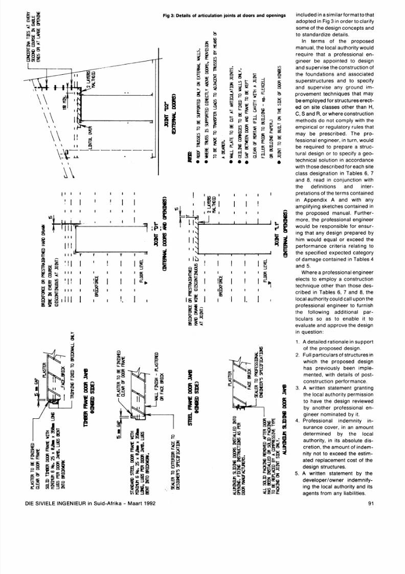
Details of ar ticulation oints at doors and openings
DIE SlVlELE INGENIEUR in Suid-Afrika Maart 1992
included in asimila rform at tothat
adopted in Fig
3
in order toclarif y
some of the design concepts and
to standardize details.
In terms of the proposed
manual the local authority would
require that a professional en-
gmeer be appo~nte d o de s~g n
and supervise theconstruction of
the foundat~ons nd associated
superstructures and to specify
and supervise any ground im-
provement techniques that may
beempl oyed for structureserect-
ed on site classes other than
H
C
S and
R
or whereconstruction
methods do not comply w~thhe
e m p ~r ~c a lr regu latory rules that
may be prescribed. The pro-
fess~onal ngineer in turn would
be required to prepare a struc-
tural design or to spe c~f y geo-
technical solution in accordance
with those descr~bedor each site
class designation in Tables
6 7
and 8 read in conjunction with
the definitions and inter-
pretatlons of the ter ms contained
~n Appendix A and w~ th any
amp l~f ylng ketches contained In
the proposed manual. Further-
more the professional engineer
would be responsible for ensur-
~ n ghat any design prepared by
him would equal or exceed the
performance criteria relatmg to
the specified expected category
of damage contained in Tables 4
and 5.
Where a professional engineer
elects to employ a construction
technique other than those des-
cribed in Tables
6
7 and 8 the
local authority could call upon the
professional engineer to furnish
the following additional par-
t~c ular s so as t o enable it to
evaluate and approve the design
in question:
1.
A deta~ledationale In support
of the proposed design.
2
Full particulars of structures in
which the proposed design
has previously been imple-
mented with deta~ ls f post-
construction performance.
3
A written statement granting
the local author~t y ermission
to have the design reviewed
by another profess~onalen-
gineer nominated by it.
4 . Professional mdemnity ~ n -
surance cover in an amount
determined by the local
authority in its absolute dis-
cretion the amount of indem-
nity not to exceed the estim-
ated replacement cost of the
design structures.
5. A
written statement by the
developerlowner indemnify-
ing the local authority and its
agents from any liabilities.
91
8/11/2019 Foundation design on poor soil
http://slidepdf.com/reader/full/foundation-design-on-poor-soil 10/14
Procedures :
The
sys temat i c cont ro l o f s t ruc tures o n pro b le m sods
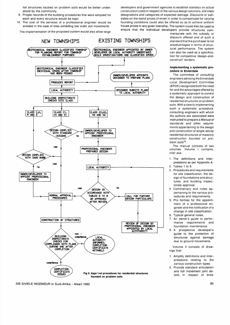
The f low char t shown in F ig 5 s um m ar i z es he p ropos ed p rocedu res
cons t i tu t ing thesys temat i c cont ro l o f bu l ld lng cons t ruc t ion on pr ob le m
soi ls f rom the t lme o f t he es tab l ishment o f t he townsh ip u p to the com -
p le t~o n f t he s t ruc tures . To fac l li t a te the examlnat lon and appro va l o f
bu i ld ing p lans , the loca l author l ty w ou ld requ i re the fo l lowing a d-
di t ional
information
t o s upp l em en t t ha t r equ i red t o b e f urn i shed i n
terms of Clause A7 of the NBR:
1
Sec t lons In two d l rec t lons through the s t ruc ture showing d eta ~ ls f
t he proposed foundat lons and re in force ment , where app l i cab le
2 Work ing drawmgs o f t hes t ruc ture a nd found at ionsshow ing a l l re le-
vant dimensions.
3 The locat ion and d eta l l s o f a l l j o~ nt s n the supers t ruc ture .
4.
The s ize and locat ion o f a l l m asonry re in forcement .
5 . A l l no tes re la t ing to spec i fi c cons t ruc t ion proced ures .
In order to enab le the loca l author i t y to eva luate the des ign pro-
posa ls submi tted a nd to prov ide a pe rman ent reco rd o f the des ign, the
fo llowing in format ion shou ld b e nser ted on the draw ings immedia te ly
above the t i t le block.
1.
Site class.
2.
Construction t ype.
3 . Category o f expec ted damage.
4. T he p ro f es si ona l engm eer s nam e , reg~ s t ra t l on um ber a nd s i gna -
ture , where a pp l i cab le .
By re ference to the above-mentioned ~ n f o rm a t i on , he bu l l d i ng
Inspec tora te wou ld be ab le to m oni tor and cont ro l t he cons t ruc t ion o f
s t ruc tures on pro b lem so l l s and p lay a m ore e f fec t ive ro le in the
~ r n ~ l e m e n t a t i o nnd enforcement o f t he N R
D CONCERTINA TIES
WENING
W C
NrEFWAL
s
RICK
WALLS
u r n
PENINGS
98
,D WR F R ME
M M .
FFL
W
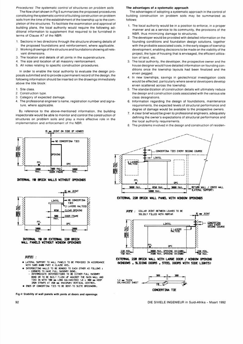
NOT S :
LATERAL SUPPORT TO WALL PANELS TO BE PR WI DE D I N ACCORDANCE
WITH SABS 486 PART K CLAUSE
KKS.
INTERSECTING WALLS TO BE BONDED TO EACH OTHER AS FOLLOWS :
K R E R S TO M F U L M Y B OW .
INTEWlEDIATE INTERSECTIONS TO
BE
EITHER FULL MWtFlY
BON OR
TO
BE
BUILT FLUSH
LP
AGAINST THE M I N WALL
AM
TIED IN WITH
788 mm
LONG GALVANIISED
1 6 X 88 m HOW
IRON
STRAPS AT
458 m V U X W l t l
VERTICAL CENTRES.
E W S
DF
U)NCER TINA TI ES TO BE BENT. TO SUI TE BRICK VOW(.
The advantages of a systematic approach
The advantages o f a dopt ing a sys temat i c approach in the cont ro l o f
budding cons t ruc t lon on prob lem so i l s may be summar ized as
fol lows:
The loca l author l ty wou ld be In a pos l tl on to enforce In a prope r
m a n n e r a n d as a s er v lc e to ~ t sommunity, the prov ls lons of the
NBR thus mln lm lz lng dam age to st ruc tures
The deve loper wo uld be prov lded wl th deta l led ln format lon on the
f o u n d ln g c o n d l t ~ o n s n d foundation d e s ~ g n
olutions
together
wl th the prob ab le ass oc~a ted os ts In the ear l y stages o f townsh lp
dev e l opm en t enabhng dec l s ~ on so b e ma de o n the v lab lh ty o f the
p ro j ec t t he ty pe o f ho us ~ nghat IS envisaged, the eff lc lent ut l l lza-
t lon of land etc
The loca l author l t y , t he deve loper , t he prospec t l ve owner an d the
hous e des ~ gne r ou l d hav e de t a ll ed l n f o rm a t l on on f oundm g c on -
d l t l ons once the to wn sh~ p ayouts had been f lna l lzed and the
e rv en pegged
In new
townships,
sav lngs In ge otec hn~ ca l nves tlgatlon cos ts
would b e e f fec ted par t~ cu la r l y here severa l deve lopers deve lop
erven scat tered ac ross the townsh lp
The s tandard lza t lon o f cons t ruc t lon deta l l s w~ l l l t ~ma te ly educe
the des lgn an d cons t ruc t lon cos ts assoc~a ted l t h the var lous s lte
c lass des lgnat lons
l n f o rm a t l on rega rdm g t he des l gn o f f ounda t ~ ons ,
maintenance
requ l rem ents the expec ted leve ls of s t ruc tura l per form ance and
degree o f damage would be a va~ lab le o the prospec t lve owners
A c lear br le f wou ld be g lven to pro fe ss~o nal ngineers adequate ly
de f l n l ng t he own e rs expectations of s t ruc tura l per form ance and
the loca l author l t y requ l rements
The pro b lems lnvo lved In the des lgn an d cons t ruc t lon o f res lden-
MTERNAL 228 RICK WALL
PANn
WITH WWOW OPENINGS
CGUAR JOINT
B E M E N
LEAKS TO
BE
ML ID L Y F IL LE D U I M MORTAR
886 M X .
OPENING
W2488
3588 I U X . OPENING
M>2588
MTOFW
228
BRICK
WALL WITH LARGE WWOW OPENING
WWOWS
SI ING
w s
sr
w s WrH SI E LIGHTS)
88
- 5 - 86
1 2 mm
THICK
GALVANIZED SHEET
WNCERTINA
TIE
Fig 4rStability of wall panels with
joints
at doors and openings
DIE S lV lELE INGENIEUR In Su ld-A f r i ka Maar t 1992
8/11/2019 Foundation design on poor soil
http://slidepdf.com/reader/full/foundation-design-on-poor-soil 11/14
t i a l s t ruc tures located on prob le m so i l s wou ld be bet ter unde r-
deve lopers and governm ent agenc ies to establish statlst lcs on actual
s t ood by t he c om m un i t y .
construct ion costs in respe ct of the various des ign solut ions, s ite c lass
9. Prope r records o f the bu i ld lng procedure s that were ado pted for des ignat ions and categor ies o f expec ted damage. Discounts or sub-
eac h and ev e ry s t ruc t u re wou l d be k ep t .
s idies on the s tand pr lces of erven in order to comp ensate for vary ing
10.
The cos t o f t he serv ices o f a pro fess iona l eng ineer would be
found ing cond i t i ons cou ld a lso be o f fered so as to ach leve un i form
avoided in the case of s l tes exhibit ing low or der soi l m ovements.
house pr i ce s in any g iven
township.
The sys tem co u ld then be used to
ensure that the ind iv idua l deve lopers prov ide s t ruc tures com-
The imp lemen ta t ion o f t he prop osed sys tem would a lso a l low large
mensurate wl th the subs idy or
discount of fered and of such a
standard that the purchaser is not
disadvan taged In terms of s t ruc-
tura l per formance. The sys tem
can also be use d as a spec i flca-
t lon for compet i t i ve des lgn-and-
construct tenders.
NEW TOWNSHIPS
EXISTING TOWNSHIPS
OTECHVICAL ENGINEER CLASSIF IES TOWNSH CHVICAL ENGMER APPOINTED BY MJNER
FOR
P L N I N G
REPORT FOR TOWNSHIP
WER
OR LOCAL AUTHOAITY INER TAK ES
ESTABLISmEKT PURPOSES IL S MS TI GA TI ON S AND CLASSIFIES
Implementing a systematic pro
cedure in Ennerdale
The commit tee of consul t ing
eng lneersadv ls lng the Ennerda le
GEOTECHVICAL W IN E E R CLASS IFIES
IMI IVI UJ AL ER KN AFTER TOCMSHIP
H S BEEN PEGGED
Loca l Deve lopment Commi t tee
(EPOK) recogn ized both the need
for and the advantages of fered by
a systemat ic appro ach to control
DESIONER SUBnITS
PLANS
TO LOCAL AUTHORITY I
t he des ign and cons t ruc t ion o f
res ident ia l s t ruc tures on prob lem
sol ls Wl th av lew to lmplement ing
such a systematic procedure,
UILDING
INSPECTORATE
I
CHECKS SITE CLASS
consul t ing engineers wi th whom
the authors are assoc iated were
ins t ruc ted to pr epare a M anual o f
s tandards an d o ther requ i re-
SIGN CM lPL IES OlrMER/MVELOPER TO
WITH STANDARO APPOINT PROFESSIONAL
DESIGNS ENGINEER
ments appe r ta in ing to the des ign
an d cons t ruc t ion o f s ing le-storey
residential s t ruc tures o f masonry
construction f o u n d e d o n p r o -
b lem so i l sz8.
The manual cons is ts of two
volumes. Volume I contains
e s
inter al ia:
1.
The def ini t ions and inter-
pretat ions as per Appendix A.
2.
Tables
1
to
9.
LOCAL AUTHORITY
1
3.
Procedures and requ i rements
for s i te c lass i f icat ion, the d e-
s ~ g n f foundat ions and s t ruc -
tures , and bu i ld ing Inspec -
OWKR DNELOPER
TO
APPOINT PAOFESSIONAL
DESIGN IN
t o ra te approva l .
4.
Commentary and notes ap-
pertaining to the varlous pro-
cedures and requirements.
ORMAL APPRWAL
TABLES
6
TO 8
PAOCUXlRES
CALL FOR FURTHER
AFTER REVIEW
5. P ro formas for the appo in t -
ment o f a pro fess iona l en-
gineer a nd the not i f icat ion of a
chang e in s i te c lass i f icat ion.
6
Typical general notes.
7 . An owner s gu ide to p er for -
mance requ i rements and
foundat ion maintenance.
CONSTRUCTION OF STRUCTURES
8. A prospec t i ve deve loper s
URING ND AFTER
guide to the pro tec t ion o f
s t ruc tures aga ins t damage
due t o g round m ov em en t s.
Volume I I cons ls ts of draw-
lngs that :
1. Ampl i f y def in i t i ons and ~nter -
pretat ions relat lng to the
various construct ion types.
2. Prov lde s tandard articulation
and fu l l movement jo in t de-
tai ls In respect of br ick
COrPLETION
CERTIFICATE
Fig
5: Appr vat procedures for residential structures
founded on problem soils
DIE S lV lELE INGENIEUR In Su id-A f r l ka Maar t
1992
8/11/2019 Foundation design on poor soil
http://slidepdf.com/reader/full/foundation-design-on-poor-soil 12/14
structures.
3. Provide details of water pipe entries and free-standing walls.
4. Contain full details of modified normal construc tion for new and
incremental brick structures founded on Class Cl , H1 and S1
sites.
5 Specify limiting dimensions of brick wall panels that contain art-
iculation joints at door openings.
The design concepts presented in Volume II relate largely to brick
structures, as distinct from blockwork, because of:
Relatively complex details required to adequately reinforce
block walls.
The inherently weak flexural tensile strength characteristics of
blockwork, which results in inadequate lateral resistance of wall
panels to lateral loading requirements (wind and imposed loads to
SABS 0160) when articulation joints are formed at doors, or when
full height/fan-light doors are provided.
Additional complexities that occur as a result of joints provided to
control shrinkage and thermal and moisture movements within the
blocks themselves.
In termsof the manual, the appointment of a professional engineer is
mandatory on all sites other than Class C, H, S and R sites where the
foundations comply with the requirement of SABS 0400, and on Class
Cl , H1 and S1 sites where the developerlowner elects to utilize the
standard modified normal construction details set out in the manual.
The manual permits a professional engineer to adopt:
1. Ageotechnical solution in accordancewith the tablesand additional
requirements set out in the manual
2. A structural solution in accordance with current technology and
proven practice and consistent with the definitions, descriptions
and illustrative drawings contained in the manual, or
3
Adesign solution not described in the manual, further particulars of
which he must furnish to the local authority.
The approach adopted in the manual differssignifican tly from that of
the Australian Standard 2870-1 986. AS 2870 provides a wider range of
empirical solutions and only requires the appointment of an engineer
to design foundations on prob lem sites (areas of mining subsidence,
uncontrolled fills, landsl ip conditions, soft soil conditions and collaps-
ing sands) and extremely reactive sites with predicted surface move-
ment in excess of 70 mm. Furthermore, engineers are requi red to
design foundations within prescribed parameters and methods on
reactive sites. However, the standard does state that the expected
damage could be as high as category
2
and assumes that the builder is
experienced in the construction of foundations and licensed in terms of
state legislation.
EPOK intends implement ing the system on all new townships, com-
mencing with Ennerdale Ext 8, adevelopment managed by the Depart-
ment of Local Government, Housing and Agriculture in the Adminis-
tration of the House of Representatives. Accordingly, the individual
erven have been classified in terms of Table 3 and the erection of
residential structures will be controlled by way of the provisions of the
above-mentioned Manual of standards and other requirements.
onclusions
Appropriate solutions for the construction of single-storey residen-
tial structures of masonry construction for the range of problem soil
sites in non-dolomitic areas encountered in South Africa can be for -
mulated. Design criteria on the basis of serviceability can be est-
ablished todefine acceptable levels of expected damage. However, he
implementation of this technology is the aspect that requires address-
ing in order to ensure that the provisionsof the NBR relating to thecon-
struction of structures founded on problem soils arecompl ied with and
appropriate solutions are adopted so as to ensure the satisfactory per-
formance of such structures.
It is our opinion that the engineering profession as well as the com-
munities served by the profession would benefit from the int roduction
of a code of practice or a manual of standards and other requi rements
appertaining to the design and construction of foundat ions and struc-
tures on problem soils based on the material presented in this paper.
Furthermore, we propose that acommit tee be established to draft such
a code to ensure that the current technology is properly an:
effectively implemented.
Future research in South Africa should focus on refining design
solutions, on reducing the increments in differential movements that
define the class of site and on the development of empi rical rules or
regulations with aview to extending the range of solutions not requi ring
professional input.
Acknowledgements
We wish to thank Dr A A B Williams and Messrs E L Giles, K Schwartz. T K
Ralph,
C
R Ringler and W K Schutte for their valuable comments on various
aspects of the material presented in this pa per. The paper is published by kin d
permission of the Department of Local Government, Housing and
Agriculture
In
the Administration of the House of Representat~ves.
References
1. Williams, A A B , Pidgeon, J T, and Day. P W Expans~ve olls. Cfv Eng S Afr,
Vol 27, No 7, July 1985.
2 Jennings J E, and Kerrich, J
E
The heaving of buildm gs and the associated
economic consequences, with particular reference to the Ora nge Free State
goldfields. Civ Eng S Afr, Vol 5 No
5
May 1963.
3. Schwartz, K. Collapsible s o~ ls . fv Engr S Afr, Vol 27, No 7, July 1985
Natlonal Bu~ldingRegulat~ons.Government Gazette, Not~ceNo 8743. 8
Sept 1987.
SABS. Code of pract ice for the application of the Natfonal Bufldfng
Regulations: SABS 0400- 1987.
Standards Assoclation of Austral~a.Residential slabs an d footings. Aus-
trahan Standard 2870-1986.
SABS. Code of practice for the design of foundatfons for buildings: SABS
0161-1980.
Pidgeon, J T. The lnteract~on n expanslve so ~l s nd a st~ffene daft founda-
tion. Proc, South Afr~ca nGeotechnical Conference, Sllverton, Nov 1980.
organwed by SAICE.
Fargher, B E. A summary of developments in the technology of footlngs in
expansfve clay soils. Miscellaneous Publica t~on o 2, Cement and Concrete
Association of Australia 1971
Dawson,
R F
Modern practices used on expanslve soils. Colorado Schoolof
Mines Quarterly V54, No 4. Oct 1959.
Lytton, R L, and Kirby, T. Stiffened mats on expanslve clays. Journal of the
Soil Mechanics and Foundations Div, ASCE, May 1971
Lytton, R L. Des~gn ethods for concrete mats on unstable so~ls. roc. Th~r d
Inter-Amer Conf on Materials Technology. Rio de Jane~ ro, razil. 1972.
G~les,E L. Repa~rof SATS houses damaged by ground movements
associated w ~t hheaving clays and collapsi ng sands Personal com-
munlcatlons, Feb 1990
K~tcher. S D Bu ~ ld ~n gouses on heavlng clay: Countlng the cost. SA
Buflder, Jan 1983.
SABS. Code of prachce for the general procedures and oadings to be adop-
ted for the desfgn of bufldfngs. SABS 0160- 1980.
Burland. J B. Broms, B B, and De Mellow, V
F
B. Behav~our f foundations
and structures. Proc, Ninth Int Conf on SM and FE, Tokyo. 1977
Watermeyer. R B Movement in masonry Chapter 12, Structural Handbook.
E l . CCE s Department. SATS, June 1986.
Giles, E L. Remedial measures for cracked houses bu ~l t n heav~ng lays.
Proc, State of the Art Sympos~um,Geotechnic al DIV, SAICE, 1985
SABS. Code of practice for the structural use of masonry SABS 0164
Part 1980
Watermeyer, R B. The des ~gn f laterally loaded unrei nforced walls. SAICE
lecture for Durban Branch. June 1989
Holland. J E. The desfgn performance and repafr of housing foundations.
Swinburne Institute of Technology, Melbourne. Nov 1981.
Holland, J E. Behav~our nd des~g n f housing slabs on f~lling. roc, Th ~r d
Australia-New Zealand Conf on Geomechanics. Wellhngton, 1980.
Yates. J R C, and Tromp. B E. Supplementary geotechnical ~nvestfgatfonor
Ennerdale Extensfon 8 township presentfng typfcal foundatfons des ~gns.
CED flle no 105111 Report DC-0111-01-00-0986, Johannesburg, 1986.
BSI. Britfsh standard code of practice for the use of masonry: Part
2
Struc-
tural use of reinforced and prestressed masonry BS 5628: Part 2: 1985.
Jenn~ngs, E, and Evans, G A. Pract~cal roceduresfor bu~l dingsn expan-
slve so11areas. R/Bou 130, NBR1, 1962
Webb. D L. Foundation and structural treatments for bu~ld~ngsn heaving
subs011 Proc, Second Int Research and Eng~neer~ngonf on Expans~ve
Clay So~l s, exas, 1969.
Pidgeon, J T, and Pellissi er, J P The behaviour of an L-shaped raft subjected
to non-uniform support conditions. R/Bou 1451, NBR1, 1987.
Soderlund and Schutte Inc in collab orat ~on lth Schwartz Tromp and Assoc.
Manualofstandardsandother requirements ppert infng to the design and
constructfon of single-storey resfdential structures of masonry constructfon
found ed on prob lem sofls. Ref 323R11190, Ennerdale Local Development
Committee. Aug 1990.
DIE SlVlELE INGENIEUR in Suid-Afr ika Maart 1992
8/11/2019 Foundation design on poor soil
http://slidepdf.com/reader/full/foundation-design-on-poor-soil 13/14
Appendix A Definitions and interpretations
The words and express ions sha l l ha ve the fo l low ing mean ings
A r t ~ c u l a t ~ o no m t s Jo in t s i n m a so n ry p ro v id e d a t su l t a b le l o ca ti o n s a n d in t e r -
vals taktng cogniz ance of the lateral stabil i ty and structural integrity of
i n d ~ v ~ d u a lane ls , enab l ing wa l l pane ls to mov e In harmony w i th the foun-
da ttons w i thou t deve lop ing s ign i f lcan t s t ress c racks o r s t ructu ra l d is t ress
Note.
1 . Wal l pane ls shou ld be designed in accordance w i th SABS 0164 Part l1 9 t o
safely resist lateral loadsz0.
2 . Jo in ts shou ld be designed to acc omm odate movem ents tha t a re p re -
dominant ly In the p lane o f the wa l l .
3 A r t lcu la t ton jo ln ts may a lso be fo rme d a t door open ings
B r~ ck f o rce i g ht w e ld e d f a b ri c co m p r i s in g t w o h a rd -d ra w n w i re s o f d ia m e t er
not exceeding 3 55 m m, he ld apar t by cross w ires, bedded in sound hor izon tal
mortar jo ints
Buddfng Inspecto ra te The bu i ld ing inspecto rste o f the loca l au thor i ty hav ing
sta tu to ry powers to con t ro l the de s~ gn nd the const ruct ion o f
buildings
Cel lu lar ra f t A foundat lon system tha t comp r ises two hor izon ta l re tn fo rced
concre te s labs in te rconnected by a ser ies o f web beams tha t by v i r tue o f
its st if fness
1
Enab les a s t ructu re to to le ra te d i f fe ren t ia l movements o r loca l tzed loss o f
suppor t (so f t spo ts3 o r
2 Reduces the d i f fe ren t ia l heave movem entsto a leve l tha t can be o le ra ted by
the superst ructu re1
wt thou t s ign i flcan t damag e
o urring
Note
1 A ce l lu la r ra f t foundat ion system has been deve loped and pa ten ted by the
CSlR and is mark e ted unde r the name 'Bouce l l Ra f t ' .
2
Th e d e s ig n m e t h o d a d o p t e d f o r h e a ve p ro f i l es sh o u ld b e b a se d o n a ' p la t e -
on-mound ora swell-under-load approachl
tha t has been proved in South
~ f r i c a ' su ch a s t h a t t n co rp ora t e d I n :
a ) The f in i te e lement p rogramme
FOCALS '
b ) L y t t o n' s m e t h o d '
C) The D iv is ion o f Bu i ld ing Techno logy S (C S I R ) M S -D OS co m p u t e r p ro -
g ram fo r s t t f fened ra f t des ign
3
Genera l ly the masonry s uperst ructu re is p rov ided w i th e i ther a r t icula t ton
jo ln ts o r l igh t re in fo rcement in o rder to fu r ther reduce crac k ing and st ruc
tural d istress
Co l lapse se t t lement The sudden se t t lement tha t occu rs when a po ten t ia l ly
co l laps ib le so i l under load IS wet ted
C o l l a p s ~ b l e s o ~ lso i l w i th a co l laps ib le so i l s t ructu re (open extu red w i th a low
d e n s~ t y ) h a t w h e n su b je c t e d t o a co m b in a t io n o f a n a p p l~ e do a d a n d a n
Increase tn so11 mo lstu re con ten t w i l l exper ience sudde n or rap id se t t le -
ment
C o m p re ss~ b le so f lA so11whose bu lk vo lum e ma y gradua l ly decrease w l th t ime
when sub jected to an app l ied load
Note A l l so i ls a re compress ib le under load However the degree o f com pres-
s ion depends on the so i l t ype and st ructu re and the magn i tude o f the
app l ied load
C o n s o l ~ d a t ~ o net t lement The ver t ica l se t t lement o r decrease in so i l vo lume
tha t occurs In a so i l under an ap p l ied s ta t ic load owing to the s low t ime-re la ted
reduct ion in the vo lume o f the vo ids
Deep strip t o u n d a t ~ o nNorm al const ruct ton w i th p recaut ions where the foun-
da t ions a re found ed a t a g rea te r dep th than norm a l on a competen t hor izon
b e lo w t h e p ro b le m so i l h o r~ zo n
Deve loper Person o r o rgan tza tton responsib le fo r the deve lopment and con-
s t ru c tl o n o f th e s t ru c t u re a n d ~ t soundat ions
D e s f g n e r P e rso n (s) a p p o in te d b y t h e o w n e r ld e ve lo p e r t o p re p a re a n d su b m i t
d rawings to the loca l au thor i ty fo r approva l
D ~ f f e r e n t ~ a leave The expected re la t ive sur face d isp lacement be tween
1. The cen t re and edge o f the mo und fo rm ed by heave movem ents
(domtng) , o r
2 . The cen tre and edge o f the d ish fo rmed by heave movements (edge heave
or dtshtng)
o f the so i l beneath a s t ructu re be fo re a l lowances fo r heave suppress ion due o
loads a re made
D~t te renba lse t t lement The re la t tve d~s p lac em ent ue to uneven se t t lement o f
d i f fe ren t por t lons o f a s t ructu re
Expanswe so f ls A f ine g r a~ ne d o i l (genera l ly w i th a h igh c lay con ten t ) tha t
changes in vo lume to vary lng degrees In response to changes in motstu re con-
tent, le th e so11may Increase in vo lume (heave o r swe l l ) upon wet t lng and de-
crease In vo lume (shr tnk) upon dry ing ou t
E xp e c t e d d am a g e A n a p p ro x im a t io n o f t h e p ro b a b le d a m a g e t h a t m a y o ccu r
in the masonry wa l ls and co ncre te f loors o f a res iden tia l s t ructu re
N o t e
1 The ranges o f damage tha t may be exper ienced are de f ined in Tab les
4
a n d 5
2 Occastona l damage in loca l ized a reas mor e severe than tha t env isaged a t
the design s tage may deve lop
3 Crack w id th is on ly one facto r in assess ing damage and shou ld no t be used
on i ts own as a d i rect measure o f damage In assessing the degree o r
sever i ty o f damage account m ust be taken o f the po in t in the s t ructu re a t
whtch i t occurs a nd a lso o f the funct ion o f the s t ructu re
F o u n d m g h o r ~ z o n sA so i l layer o r s t ra tum
exhibiting
simllar geotechnical and
eng ineertng p roper t ies and characte r is t tcs tha t suppor ts a s t ructu re
Fu l l m o ve m e n t l o f n t s Articulation jo tn ts tha t a re designed to accomm odate
movemen ts bo th in and ou t o f the p lane o f the wa l l
Ge o t e ch n ~ ca le n g m e e rA pro fess iona l eng ineer competen t in he d isc ip l ine of
so11mechan ics appo in ted b y e l ther the loca l au thor t ty o r the owner ldeve loper
to c lass i fy the s i te
Heave/shr fnkage The anticipated su r f a ce m o ve m e n t p ro d u ce d b y a n e xp a n -
s ive so i l hor izon caused by mo lstu re changes w i th in the hor izon
Increm enta l hous e Any res lden t ta l s t ructu re tha t fo r reasons o f a f fo rdab i lt t y
IS
to be c onst ructed In s tages in such a manner tha t in i t s in te rmed ia te s tages
the st ructu re can be occup ied by i t s owner
L ~ g h t l ye ~ n t o rc e d lo ckw o rk B lo ckw o rk h a v~ n g o ri zo nt a l r e in fo r ce m e n t
L ~ g h t l yemfor ced bnck work B r ickwork having hor izon ta l bed o in t re in fo rce-
m e n t n o t e xce e d in g 6 m m n d ia m e t e r b e d d e d n so un d m o r t a r j o in t s i n a d d
t io n t o b r i ck f o r ce
Masonry Anas semb lanceo f s t ructu ra l un i ts la id ins i tu inwh ic h hest ructu ra l
un i ts a re bonded and so l id ly pu t toge ther w i th mor ta r o r g rou t
N o t e
1 Masonry may be re in fo rced o r unre in fo rced
2 Masonry un i ts may be descr ibed as b r icks o r b locks depend ing on
t h e i r d im e n s~ o n s
3
A b lock is a masonry un i t tha t when used in i t s norma l aspect is more than
300 m m l o n ~ 5 0 m m w id e o r 1 2 0 m m h ig h
4 S t a n d a rd f o rm a t b r i cks a re 2 2 2 m m lo n g l0 6 m m w id e a n d 7 3 m m
high
o d ~ f ~ e d n o rm a l c o n s t r u c t ~ o n
orma l const ruct ion w i th
precautions
art icula-
t ion jo ln ts a t doors and open lngs l tgh t re in fo rcement in masonry and re~ nfor -
cement In concre te s t r ip foo t ings
N o r m a l construction Unre in fo rced conc re te s t r ip foo t ings w i th p la in masonry
superst ructu res bu i l t in accordancewl th the empir ica l ru les con ta ined in SABS
0400 Par ts H a n d K
N o r m a l c o n s tr u c t fo n w ~ t h re ca u t f o n s N o rm a l co n s t ru ct i o n e xc lu d ing t h e u se
of th ickened f loor s lab foundat ions under ~n te r na l a l ls w i th mandatory s i te
dra inage and p lumbing insta l la t ion p recaut ions
Owner Person in whom the lega l t i t le o f the p roper ty
IS
vested and who is re -
sponsib le fo r the m a in tenance o f the bu i ld ing and the s i te
P fer o undat lon Masonry re in fo rced concre te o r mass concre te co lum n w i th
or w l thou t a pa d foo t ing designed to t ransfer s t ructu ra l loads to a su itab le
f o u n d in g h o r i zo n
P ~ l e A re in fo rced concre te co lumn shaped member des igned to t ransfe r
s t ru c tu ra l l o a d s t o a su ~ t a b leoundtng hor izon
P ro b le m soils Found ing hor tzons tha t possess one o r more o f the fo l low-
ing charactertst lcs
1 Expansive
2 Compress ib le
3
Col laps ib le
N o t e O t h e rg e o te ch n ica l p ro b le m s m a y b e e n co u n t e re d e g in a re as u n d e r la m
by do lomites and sha l low m in ing work ings o r where uncont ro l led land f tl l has
been p laced
Pro fessfona l engmeer A c lv i l eng ineer who is reg is te red in te rms o f the p ro
vts tons o f sect lon 18 o f the Pro fess iona l Eng ineer
S
Act 1968 (Act 81 o f
1968)
Rem forced b lockwo rk B lockwork having hor izon ta l and ver t ica l g rou ted s tee l
re in fo rcement in accordanc e w l th BS 5628 Par t 2
Refn fo rced bnckwork B r ickwork having s tee l re in fo rcement bo th in the bed
jo in ts and In g rou ted cav i t ies in accordance w i th BS 5628 Par t 2
S ~ g n ~ h c a n tamage Damage in masonry wa l ls and concre te floors equa l to o r
g rea te r than ca tegory
3
dama ge as re fe r red to in Tab les 4 and 5
S i te c lass The ca tegor iza tion o f a s i te by a geo techn ica l eng ineer in te rms o f
Tab le 3
S p l f t co n s t ru c t ~ o nA const ruct ion techn ique2
26
in wh ich thest ruc tu re o f the
b u i l d in g i s p ro v id e d w ~ t h u ff i c ie n t f l e x~ b t l i t yo a cco m m o d a t e t h e d l ff e re n t ~ a l
m o ve m e n t s o f t he f o u n d m g h o r i zo n b y m e a n s o f a co m b ~ n a t t o n f f u ll m o ve -
ment jo in ts re in fo rced b r ickw ork lb lo ckwo rk s t i f fened st r tp - foo t ings and
f lo a t i n g / su sp e n d e d fl o o rs w i t h o u t s ig n i f ~ ca n t a m a g e o ccu r r i n g
DIE SlVlELE INGENIEUR
in
Suid-Af r ika
Maart 1992
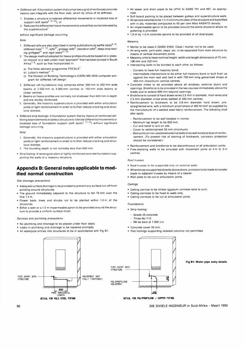
8/11/2019 Foundation design on poor soil
http://slidepdf.com/reader/full/foundation-design-on-poor-soil 14/14
S t ~ f f e n e d ra f tA f o u n d a t ~ o n ys t e m t h a t comprises a g r ~ df r e ~ n f o r c e d oncre te
b e a m s ca st ~ n t e g ra l l y ~ t h h e fl o o r s la b w h lch b y v i r t ue o f ~ t s t l f fness
1
E n a ble s a s t ru c tu re t o t o le ra t e d ~ f f e re n t ~ a lo ve m e n t s o r l o ca l~ ze doss o f
suppor t (so f t spo ts3 o r
2
R e d u ce s t h e d l f f e re n t ~ a l eave movements to a leve l tha t can be o le ra ted by
the superst ructu re7
w ~ t h o u t i g n ~ f ~ c a n ta m a g e o ccu r r ln g
Note.
S t i ffened ra f ts a re a lso des cr~ bed n s o m e p u b l ~ c a t ~ o n ss waff le slabsg. 1°
s t ~ f f e n e d a t s1 ' . . ra f ts2 ' , g r~ l lageaf tss, s tand ard ra f ts9 , deep stnp foo t -
~ n gr i l lages21 and r ig id s labs2 ' .
Th e d e s~ g n e t h o d a d o p t e d fo r h e a ve p ro f ~ le s h o u ld b e b a se d o n a ' p la t e -
on-m ound ' o r a 'we l l -under- load ' approach1 tha t has been proved In South
~ f r ~ c a ' .
.
su ch a s t h a t ~ n co rp o ra t e d n:
a ) Th e f ~ n l t e le m e n t p ro g ra m m e FOCALS'
b) Lyt ton 's method ' l
C ) T he D lv ts io n o f B u ~ l d ~ n ge ch n o lo g y' s (C S I R ) M S -D OS co m p u t e r p ro -
g r a m f o r s t ~ f f e n e d a f t d e s ~ g n .
S t ~ f f e n e d a ft f o u n d a t ~ o n sm a y c o m pr l se e ~ t h e r 0 0 m m t o 4 50 m m w ~ d e
beams a t
2
5 0 0 m m t o 4 00 0 m m c e n tr e s o r 1 50 m m w ~ d e e a m s a t
c loser cen t res
Beams on heave p ro f l les a re norma l ly no t sha llower than 600 m m ~ndepth
a n d a re d o u b ly re ~ n f o rce d
Genera l ly the masonry superst ructu re IS p r o v ~ d e d ~ t h ~ t h e r r tl c u la t lo n
p n t s o r l t gh t r e ~ n f o rce m e n t n o rd e r to f u r t he r r e d u ce c ra ck~ n g n d s t ru c
t u ra l d s t re s s
S t ~ f f e n e d s t n po o t in gs . A f o u n d a t ~ o n ys t e m t h a t b y m e a n s o f r e ~ n f o rce d tl f -
f e n ~ n g e a m e le m e n t se n a b le sa s t ru c tu re to t o lera t e d ~ f f e re n t ~ a lo ve m e n t so r
loca l tzed loss of foun dat ~on uppor t (so f t spo tsH1
23
without s lgn l f lcan t
damage occurr lng
N o t e
1 Genera l ly the masonry superst ructu re IS p ro v~ d e d l t h e ~ t h e r rt l cu la t l o n
j oi nt s o r l ~ g h te~nfo rcem ent n rder to fu r ther reduce cracktng and struc-
t u ra l d ~ s t re ss
2 T h e f o u n d ~ n g e p t h IS n o t n o rm a l l y l e ss th a n 6 0 0 m m
S t r i p f o o t ~ n gA re c t a n g u la r p la ~ n o r g h tl y r e ~ n f o rce d o n c re t e f o u n d a t lo n su p -
por t lng the wa l ls o f a masonry s t ructu re
Appendix B General notes applicable to mod
ified normal construction
A d e q u a t e su r f a ce d ra t n a g e t o b e p ro v ~ d e do p re ve n t an y su r f ace ru n -o f f r o m
p o n d ~ n g r o u n d s t ru c tu r e s
T h e g r o u n d ~ m m e d ~ a t e l yd jacen t to the s t ructu re to fa l l 75 m m over the
ftrst 1 5 m
F lo we r b ed s t r ee s a n d sh ru b s n o t t o b e p la n t ed w ~ t h ~ n5 m o f t h e
st ructu res
E ~ t h e r l a w n o r a
l
m ~ m p e r m e a b l e p r o n t o b e p r o v ~ d e d r o u n d t h e s tr u c -
t ur e to p r o v td e a u n ~ f o r m u rf ac e f ~ n ~ s h
S e r v ~ c e s n d p l u m b ~ n g r e c a ut i o n s
N o p l u m b m g a n d d r a ~ n a g e o be p laced u nder f loor s labs.
L e a ks In p l u m b ~ n g n d d r a ~ n a g eo b e re p a l re d p ro m p t l y
A l l wa te rp lpe en t r ies In to s t ructu res to be In accordance w l th Fig B1
A l l se we r a n d d ra ~ n ip e s to b e u P V C t o S A B S 7 9 1 a n d 9 6 7 a s a p p ro p -
r ia te
Sof t boar d packtng to be p laced be tween gu l leys and superst ructu re wa l ls
A l l se rv l ce tr e n ch e s to b e 1 . 5 m (m t n ~ m u m ) le a r o f t h e s t ru c t u re a n d b a ck f ~ l l e d
w ~ t hn s~ t u a t e r~ a l s o m p a c t e d t o 9 0 p e r ce nt M o d A A S H TO d e n s tt y
A n m p e rm e a b le a p ro n t o b e p ro v ld e d a ro u n d t h e e n tt r e s t ru c t u re wh e re n o
guttering IS p r o v ~ d e d
1,O m b y 1,O m co n c re te a p ro n s t o b e p ro v ~ d e d t al l d o w n p ~ p e s
M a so n ry
Morta r to b e c lass I I (SABS 0164) C lass I mor ta r no t to be used.
A l l w lng wa l ls , ya rd wa l ls , s teps, e tc . to be separa ted f rom maln s t ructu re by
means o f ver t ica l m ovement jo in ts .
Masonry un t ts to have nomina l he igh t . w ~ dt h n d le n g t h d im e n s~ o n s f 7 5 m m ,
1 0 6 m m a n d 2 2 2 m m
ln te rse ct~ng a l ls to be bonded to each o ther as fo l lows:
C o rn e rs t o h a ve fu l l m a so n ry b o n d
l n t e r m e d ~ a t en t erse ct l on s t o b e e ~ t h e r u l l masonry bo nd or bu l l t f lush up
a g a tn s t th e m a in w a ll a n d t ~ e dn w l t h 7 0 0 m m lo n g g a lva n ~ ze d t r a p s a t
4 5 0 m m maximum) ver t lcal ce n t res
C o n c re t e l hn te ls t o b e p ro v ~ d e d b o ve a l l w ~ n d o w s e x t e rn al d o o rs a n d
o p e n ln g s B r t ck fo r ce t o b e p ro v~ d e dn t he t w o c o u rs e s ~ m m e d ~ a t e l ybove the
l tn te ls and to extend 600 mm bey ond open lngs
B r ~ c k f o r c eo consls t o f hard d rawn w lres 3 5 m m I n d ~ a m e t e rma ln w lres and
2
5 m m d ~ a m e t e r r o ss w l re s w e ld e d a t 3 0 0 m m ce n t re s
R e ~ n f o rc e m e n t o b r ~ c k w o r k o b e
5
8 m m d ~ a m e t e r h a rd d ra w n p re -
s t ra ~ g h t e n e d i r e w t th a m ln lm u m p ro o f st r ess o f 48 5 N / m m 2 as supphed by
t h e m a n u f a c tu re r o f a w e ld e d s t e e l f a b r ~ c e ~ n f o rce m e n t Th e
following
shall
a lso app ly
R e ~ n f o rce m e n t o b e w e l l b e d d e d ~ n morta r
M ~ n ~ m u ma p le n gt h t o b e 6 0 0 m m
C u t a n d b e n d t o su ~ t n s l te
C o ve r to r e ~ n fo r ce m e n t 0 m m ( m ~ n ~ m u m )
Bed o ln tso n n on-p laste red exte rna l wa l ls to be we l l too led a t leve l of re ln fo r -
ce m e n t (To p re ve n t r~ sk f s t a ln ln g of b r~ ck w o rk
corrosion
pro tect lon
sh o u ld b e co n s t d e re d
)
R e ~ n f o r c em e n t n d b r c k f o r c e to b e d ~ s c o n t ~ n u o u st all art lculat lon lo lnts
F re e -s t a n d in g w a l l s t o b e p ro v~ d e dw ~ t hmovement jo ln ts a t 4 m to 5 m
centres.
Roof t russes
Roof t russes to h e suppor ted on ly on exte rna l wa l ls
Wh e re t ru ss ssu p p o r t e d d ~ re c t l y b o ve d o o rs , p ro v l s lo n o b e m a d e t o t ra n s f e r
loads to ad jacent t russes by mea ns o f a bearer .
Wa l l p la te to b e cu t a t a r t ~ cu la t ~ o no m t s
C e ~ l ~ n go rn l ce t o b e t ~ m b e r g yp su m co rn i ce s t en d t o cu r l )
Ce ihng corn ices to be f ixed to wa l ls on ly .
C e ~ h n g o rn l ce s t o b e cu t a t a r t i cu la t io n j o ~ n t s .
Foundat ions
PIPE ENTRY INTO
STRUCTURE
HOLDERBAT (NOT
FULLY TIGHTENED)
Grade 25 concre te
Three N o Y12
R 6 t l e b a rs a t 1 0 0 0 c l c
Concre te cover 50 mm.
Pad foo t~ ngs uppor t ing Iso la ted co lum ns no t permt t ted
F i g
B :
Wa t e r p ip e e n t r y d e t a i l s
POLYPROPYLENE
HOLDERBAT
D E T I L
FOR ST L
PIPING
k
DETAIL
FOR P O L Y A a P Y l
/ LIPPER P I P N