Embed Size (px)
Citation preview
1
FOSC 450 B6ClosureI N S T A L L A T I O N I N S T R U C T I O N
Fiber Optic Splice Closure
1.0 General Product Description
The FOSC 450 �ber optic splice closures use compressed-gel cableseals to environmentally seal �ber cable splice points.
The maximum single splice capacity of the FOSC 450 B6 closure is144 with 24 splices stored on six trays. The maximum mass fusionsplice capacity is 288, only four trays are needed.
A larger FOSC 450 D6 closure is also available. Splice capacities forthe D size are 576 for single splicing and 1152 for mass splicing.
Note: Cable blocking is not recommended in this closure dueto the space constraints. If cable blocking is used, follow thespecial instructions in "D/Gel Cable Block" installation instruc-tions.
2.0 Kit Contents
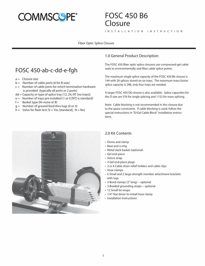
• Dome and clamp• Base and o-ring• Metal slack basket (optional)• Gel end-piece• Velcro strap• 4 Gel end-piece plugs• 2 or 6 Cable strain relief holders and cable clips• Hose clamps• 6 Small and 2 large strength member attachment brackets
with lugs• 3 Bond clamps (3" long) -- optional• 3 Braided grounding straps -- optional• 12 Small tie wraps• 1/4” Nut driver to install hose clamp• Installation Instructions
FOSC 450-ab-c-dd-e-fgha = Closure size b = Number of cable ports (6 for B-size)c = Number of cable ports for which termination hardware is provided (typically all ports or 2 ports)dd = Capacity or type of splice tray (12, 24, NT [no trays])e = Number of trays pre-installed (1 or 0 [NT] is standard)f = Basket type (N=none or B)g = Number of ground feed-thru lugs (0 or 3)h = Valve for �ash test (V = Yes [standard], N = No)
2
Other Accessory Kits:
• FOSC-ACC-B-Tray-12, 16 and 24 (tray kit)• FOSC-450-Cable-Term-4-N or FOSC-450-Cable-Term-4-G (ground-ing). Contains 4 replacement cable termination components, can beordered with or without grounding.• FOSC-ACC-B-Bracket • FOSC-ACC-450-Workstand• FOSC-ACC-Wall/Pole-Mount• FOSC-ACC-Aerial-Clamp• FOSC-ACC-Aerial-SWVL-Mount• FOSC-ACC-Aerial-Clamp• FOSC 450 Small/Seal-4 Cable Kit• FOSC 450 Small/Seal-3 Cable Kit
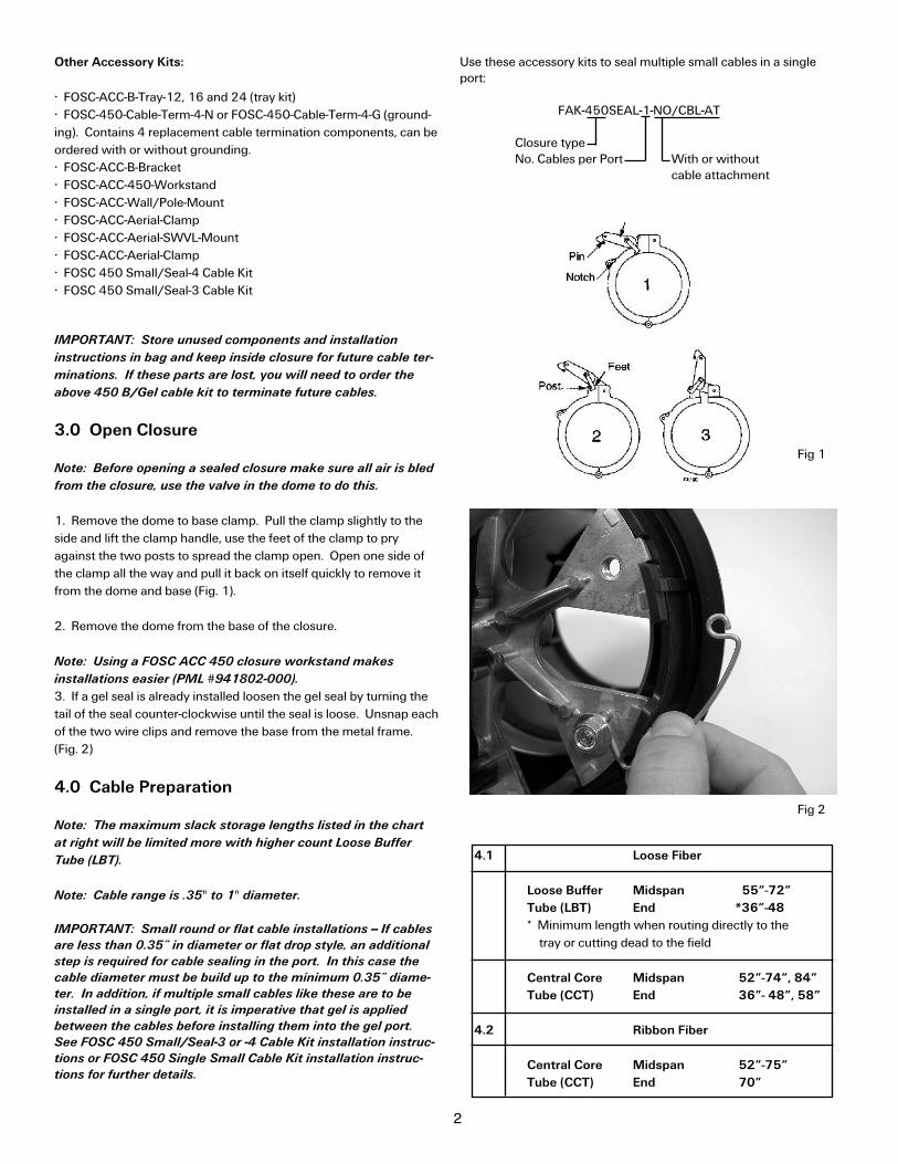
Use these accessory kits to seal multiple small cables in a singleport:
FAK-450SEAL-1-NO/CBL-AT
Closure typeNo. Cables per Port With or without
cable attachment
IMPORTANT: Store unused components and installation
instructions in bag and keep inside closure for future cable ter-
minations. If these parts are lost, you will need to order the
above 450 B/Gel cable kit to terminate future cables.
3.0 Open Closure
Note: Before opening a sealed closure make sure all air is bled
from the closure, use the valve in the dome to do this.
1. Remove the dome to base clamp. Pull the clamp slightly to the side and lift the clamp handle, use the feet of the clamp to pryagainst the two posts to spread the clamp open. Open one side ofthe clamp all the way and pull it back on itself quickly to remove itfrom the dome and base (Fig. 1).
2. Remove the dome from the base of the closure.
Note: Using a FOSC ACC 450 closure workstand makes
installations easier (PML #941802-000).
3. If a gel seal is already installed loosen the gel seal by turning thetail of the seal counter-clockwise until the seal is loose. Unsnap eachof the two wire clips and remove the base from the metal frame.(Fig. 2)
4.0 Cable Preparation
Note: The maximum slack storage lengths listed in the chart
at right will be limited more with higher count Loose Buffer
Tube (LBT).
Note: Cable range is .35" to 1" diameter.
IMPORTANT: Small round or flat cable installations -- If cables
are less than 0.35” in diameter or flat drop style, an additional
step is required for cable sealing in the port. In this case the
cable diameter must be build up to the minimum 0.35” diame-
ter. In addition, if multiple small cables like these are to be
installed in a single port, it is imperative that gel is applied
between the cables before installing them into the gel port.
See FOSC 450 Small/Seal-3 or -4 Cable Kit installation instruc-
tions or FOSC 450 Single Small Cable Kit installation instruc-
tions for further details.
Fig 1
Fig 2
4.1 Loose Fiber
Loose Buffer Midspan 55”-72”
Tube (LBT) End *36”-48
* Minimum length when routing directly to thetray or cutting dead to the field
Central Core Midspan 52”-74”, 84”
Tube (CCT) End 36”- 48”, 58”
4.2 Ribbon Fiber
Central Core Midspan 52”-75”
Tube (CCT) End 70”
Note: If mass fusion splicing of ribbons is to be done, the ribbons must be routed to the slack basket �rst. Do not routethese ribbons directly to the tray unless they will be de-ribbonized for single splicing.
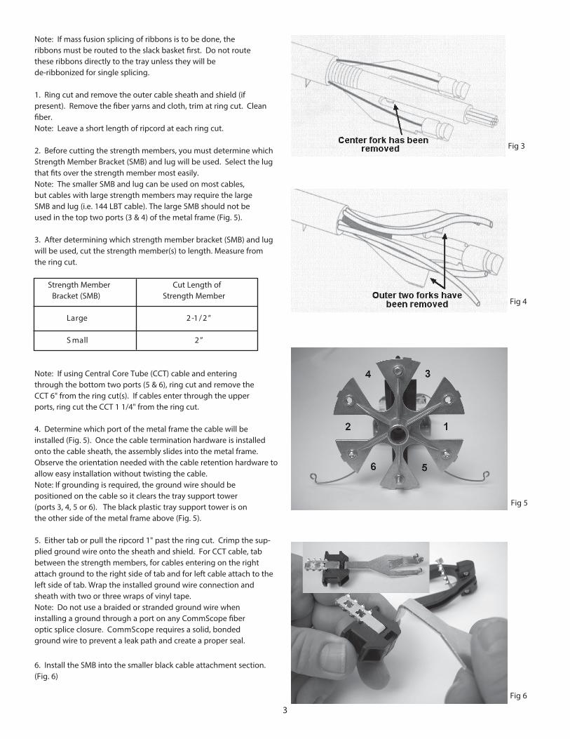
1. Ring cut and remove the outer cable sheath and shield (if present). Remove the �ber yarns and cloth, trim at ring cut. Clean�ber.Note: Leave a short length of ripcord at each ring cut.
2. Before cutting the strength members, you must determine whichStrength Member Bracket (SMB) and lug will be used. Select the lugthat �ts over the strength member most easily.Note: The smaller SMB and lug can be used on most cables,but cables with large strength members may require the largeSMB and lug (i.e. 144 LBT cable). The large SMB should not beused in the top two ports (3 & 4) of the metal frame (Fig. 5).
3. After determining which strength member bracket (SMB) and lugwill be used, cut the strength member(s) to length. Measure fromthe ring cut.
Note: If using Central Core Tube (CCT) cable and enteringthrough the bottom two ports (5 & 6), ring cut and remove theCCT 6" from the ring cut(s). If cables enter through the upperports, ring cut the CCT 1 1/4" from the ring cut.
4. Determine which port of the metal frame the cable will beinstalled (Fig. 5). Once the cable termination hardware is installedonto the cable sheath, the assembly slides into the metal frame.Observe the orientation needed with the cable retention hardware toallow easy installation without twisting the cable.Note: If grounding is required, the ground wire should be positioned on the cable so it clears the tray support tower(ports 3, 4, 5 or 6). The black plastic tray support tower is onthe other side of the metal frame above (Fig. 5).
5. Either tab or pull the ripcord 1" past the ring cut. Crimp the sup-plied ground wire onto the sheath and shield. For CCT cable, tabbetween the strength members, for cables entering on the rightattach ground to the right side of tab and for left cable attach to theleft side of tab. Wrap the installed ground wire connection andsheath with two or three wraps of vinyl tape.Note: Do not use a braided or stranded ground wire wheninstalling a ground through a port on any CommScope �beroptic splice closure. CommScope requires a solid, bondedground wire to prevent a leak path and create a proper seal.
6. Install the SMB into the smaller black cable attachment section.(Fig. 6)
Fig 3
Fig 4
Fig 5
Strength Member Cut Length ofBracket (SMB) Strength Member
”2/1-2egraL
”2llamS
3
Fig 6
4
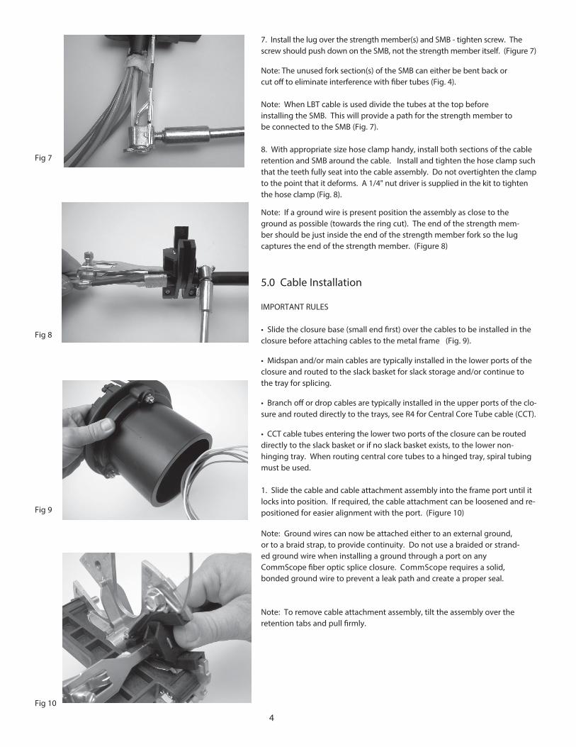
7. Install the lug over the strength member(s) and SMB - tighten screw. Thescrew should push down on the SMB, not the strength member itself. (Figure 7)
Note: The unused fork section(s) of the SMB can either be bent back orcut o� to eliminate interference with �ber tubes (Fig. 4).
Note: When LBT cable is used divide the tubes at the top beforeinstalling the SMB. This will provide a path for the strength member tobe connected to the SMB (Fig. 7).
8. With appropriate size hose clamp handy, install both sections of the cableretention and SMB around the cable. Install and tighten the hose clamp suchthat the teeth fully seat into the cable assembly. Do not overtighten the clampto the point that it deforms. A 1/4" nut driver is supplied in the kit to tightenthe hose clamp (Fig. 8).
Note: If a ground wire is present position the assembly as close to theground as possible (towards the ring cut). The end of the strength mem-ber should be just inside the end of the strength member fork so the lugcaptures the end of the strength member. (Figure 8)
5.0 Cable Installation
IMPORTANT RULES
• Slide the closure base (small end �rst) over the cables to be installed in theclosure before attaching cables to the metal frame (Fig. 9).
• Midspan and/or main cables are typically installed in the lower ports of theclosure and routed to the slack basket for slack storage and/or continue tothe tray for splicing.
• Branch o� or drop cables are typically installed in the upper ports of the clo-sure and routed directly to the trays, see R4 for Central Core Tube cable (CCT).
• CCT cable tubes entering the lower two ports of the closure can be routeddirectly to the slack basket or if no slack basket exists, to the lower non-hinging tray. When routing central core tubes to a hinged tray, spiral tubingmust be used.
1. Slide the cable and cable attachment assembly into the frame port until itlocks into position. If required, the cable attachment can be loosened and re-positioned for easier alignment with the port. (Figure 10)
Note: Ground wires can now be attached either to an external ground,or to a braid strap, to provide continuity. Do not use a braided or strand-ed ground wire when installing a ground through a port on any CommScope �ber optic splice closure. CommScope requires a solid,bonded ground wire to prevent a leak path and create a proper seal.
Note: To remove cable attachment assembly, tilt the assembly over theretention tabs and pull �rmly.
Fig 7
Fig 8
Fig 9
Fig 10
5
6.0 Cable Routing
Note: If this is a new closure, remove any installed trays that
might make fiber routing easier. Install trays as you go. Refer
to section 4.0 for cable preparation.
Go to:6.1 for Loose Buffer Tube Cable6.2 for Central Core Tube Cable
6.1 Loose Buffer Tube Cable Installation
1. Review IMPORTANT RULES from pg. 4.
Note: If the LBT cable contains the older style stiff LBT’s, it will
be necessary to ring cut the LBT 1-1/2” from the ring cut and
install transportation tubes over the LBT for routing.
2. Route loose buffer tubes (LBT) either to the basket for slack storage or to the tray for splicing. LBT’s can be routed directly fromthe port to the tray or from the basket to the tray(s).
Note: If installing a midspan and need to splice only part of the
fibers in a loose buffer tube (LBT), go to step 6.
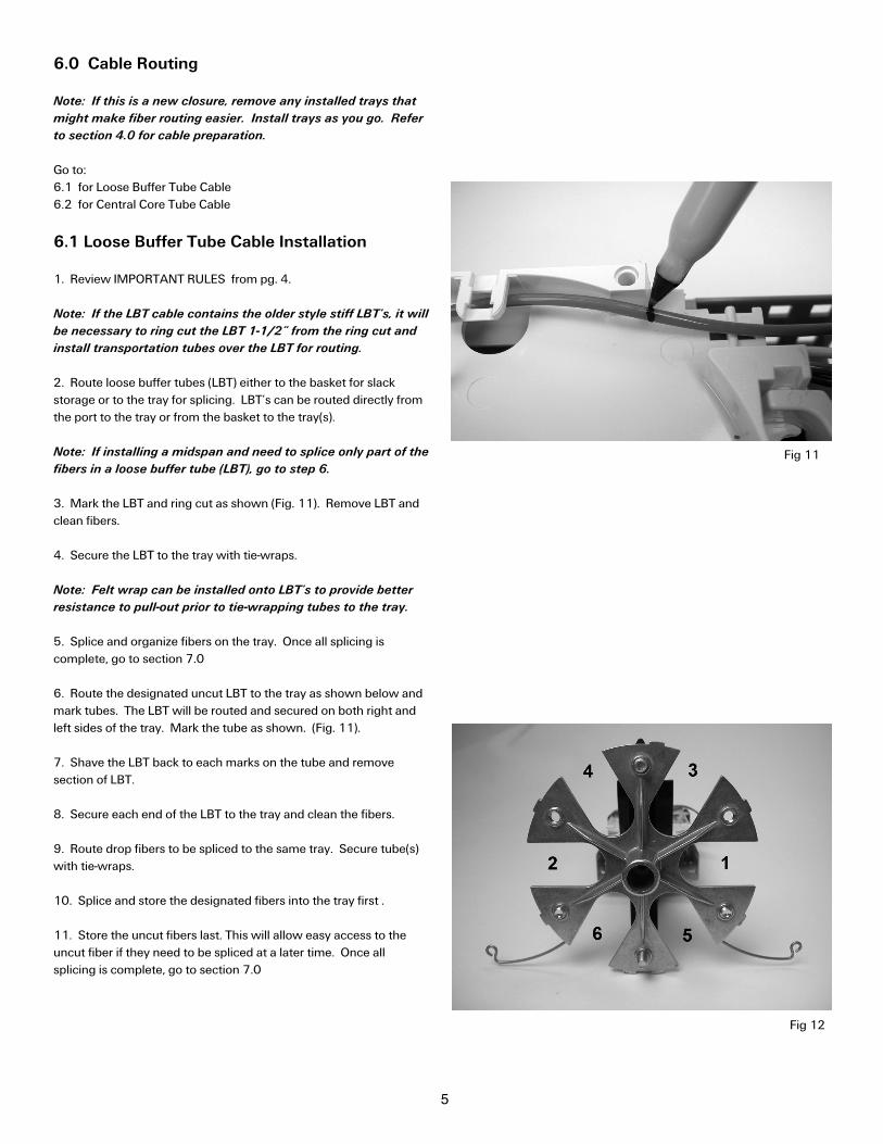
3. Mark the LBT and ring cut as shown (Fig. 11). Remove LBT andclean fibers.
4. Secure the LBT to the tray with tie-wraps.
Note: Felt wrap can be installed onto LBT’s to provide better
resistance to pull-out prior to tie-wrapping tubes to the tray.
5. Splice and organize fibers on the tray. Once all splicing is complete, go to section 7.0
6. Route the designated uncut LBT to the tray as shown below andmark tubes. The LBT will be routed and secured on both right andleft sides of the tray. Mark the tube as shown. (Fig. 11).
7. Shave the LBT back to each marks on the tube and remove section of LBT.
8. Secure each end of the LBT to the tray and clean the fibers.
9. Route drop fibers to be spliced to the same tray. Secure tube(s)with tie-wraps.
10. Splice and store the designated fibers into the tray first .
11. Store the uncut fibers last. This will allow easy access to theuncut fiber if they need to be spliced at a later time. Once all splicing is complete, go to section 7.0
Fig 11
Fig 12

6
6.2 Central Core Tube Cable Installation
1. If cable(s) enter through the bottom two ports (5 & 6), core tubescan be routed directly to the slack basket or non-hinging bottom trayand secured with tie-wraps - do not over tighten. The core tubesshould already be cut to 6" length.
If cable(s) enter through the middle or upper ports (1, 2, 3, or 4 -- SeeFigure 12) hold the section of (large) spiral wrap up to the ring cut ofthe cable and route it to the tray or basket location where fibersneed to go. Allow a generous length for tray hinging, and cut the spi-ral tubing to length and install it over the fibers and central core tube(CCT). Make sure the spiral tube is pushed all the way up betweenthe strength members and CCT. This will help secure the spiralwrap. Also, make sure there is enough length of tubing on the tray,or basket, for two tie-wraps - do not over tighten.
Note: Generally speaking, ribbons should be routed to the
slack basket and not directly to the trays. Ribbon slack should
not be stored on the tray. Do not route ribbons directly to the
tray unless the ribbons will be de-ribbonized for single splicing.
Note: Go to section 6.3 for Central Core Tube Ribbon Cable.
2. If fibers are on the tray, splice and organize fibers. Once all splicing is complete go to section 7.0 If fibers are in the slack basket, continue to step 3.
3. Select fiber(s) to be cut or routed.
Note: Selected midspan fibers can be cut in the middle of the
loop to splice to either end, but if more length is needed, cut
offset from midpoint (short end fibers will be dead to the field).
4. Fibers will be transported to the opposite side of the basket androuted to appropriate trays using the transportation tubes. Attachtransportation tubes to the basket. Tubes can be identified at bothends with feed (blue) and distribution (white) labels. Take transporta-tion tube behind the tray tower and attach to tray with tie-wraps.
5. Splice and organize fiber. Once all splicing is complete, go to section 7.0
6.3 Central Core Tube Ribbon Cable
1. Layout and separate ribbons. Select ribbons to be cut or routed.
Note: Selected midspan ribbons can be cut in the middle of the
loop to splice to either end. This will allow 15" to 24" for splic-
ing. If more length is needed, cut offset from midpoint (short
end ribbons will be dead to the field).
2. Ribbons will be transported to the opposite side of the basket androuted to appropriate trays using the ribbon transportation tubes(green rubber band group). Attach transportation tubes to the bas-ket leaving 6" in the basket. Tubes can be identified at both endswith feed (blue) and distribution (white) labels. Route the transporta-tion tube behind the tray tower and attach to tray with tie-wraps.
Note: Arrange the order of ribbons before inserting them into
the transportation tube. This will eliminate crossing of ribbons
on the tray.
Fig 14
Fig 15
Fig 16
Fig 13

7
3. Feed arrangement of designated ribbons (groups of six) into thetubes in the basket and pull ribbons through transportation tubes ontothe tray- leaving a small loop in basket. Ribbons on one side of trans-portation tube may need to be oriented in an opposite order to preventcrossover of ribbons on the tray. (Figure 13)
4. Pull enough ribbon length through the transportation tubes to complete splicing.
5. Splice ribbon ends, allow generous bend when routing (six splicesper tray recommended). (Fig. 14)
6. Ribbons can be pulled back into the basket. Pull all the ribbons inthe group at the same time.
Note: Do not store ribbon loops on the tray.
7. Store slack ribbon length in the slack basket and hold down storedribbons with tie-wraps, leave the tie-wraps loose to avoid unnecessarypressure in the ribbons. Once all splicing is complete, go to section 7.0
7.0 Gel End-Piece Installation
1. Make sure the gel end piece is not already compressed. Turn the"tail" of the gel end piece counter clockwise to ensure that the seal is inthe un-compressed position. Squeeze the gel end piece to unlatch andopen each half one at a time. (Figure 15)
2. Install the gel end piece around the cables. Position it against thespacer on the metal frame. Snap both halves of the gel end piecetogether. (Figure 16)
3. Important: Insert one port plug in each unused port (Fig. 17)
4. Slide the base up and over the gel end piece, make sure the wireclips and ground wires are back out of the way. Make sure to line upthe arrow on the base (Figure 18) with arrow on the top of the frame(Figure 19).
Once the base is in position, snap the wire clips into the base by push-ing firmly on the clips (Figure 20).
5. Connect any ground wires attached to the cables to the nearestground wire that leads to the ground feedthroughs in the base.
6. Turn the "tail" clock-wise until it dead ends at the physical stop orbecomes tight (Figure 21). A screwdriver can be installed through thehole in the tail to tighten the seal. Hold the screwdriver tightly so itdoes not come out.
7. Place a large tie-wrap around all the cables near the end of the tail.
Once the plugs are installed and the gel end piece is tightened go
to section 8.0.
Fig 17
Fig 18
Fig 19
8.0 Close the Closure
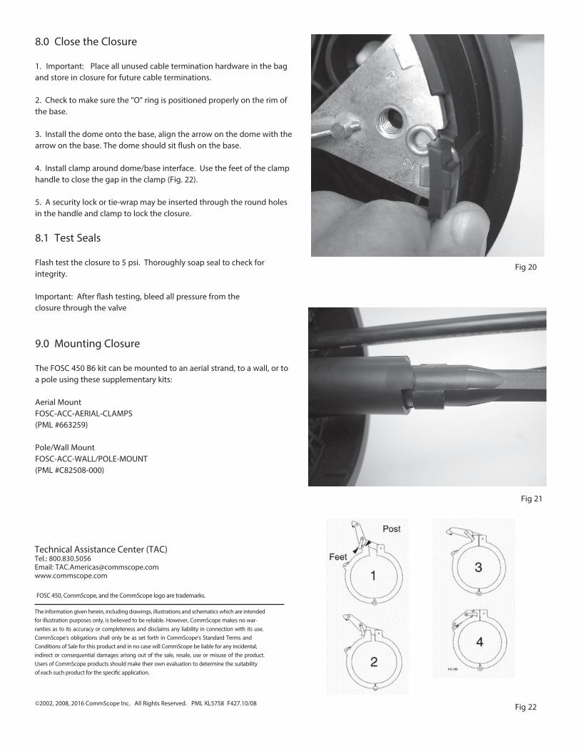
1. Important: Place all unused cable termination hardware in the bagand store in closure for future cable terminations.
2. Check to make sure the "O" ring is positioned properly on the rim ofthe base.
3. Install the dome onto the base, align the arrow on the dome with thearrow on the base. The dome should sit �ush on the base.
4. Install clamp around dome/base interface. Use the feet of the clamphandle to close the gap in the clamp (Fig. 22).
5. A security lock or tie-wrap may be inserted through the round holesin the handle and clamp to lock the closure.
8.1 Test Seals
Flash test the closure to 5 psi. Thoroughly soap seal to check forintegrity.
Important: After �ash testing, bleed all pressure from the closure through the valve
9.0 Mounting Closure
The FOSC 450 B6 kit can be mounted to an aerial strand, to a wall, or toa pole using these supplementary kits:
Aerial Mount FOSC-ACC-AERIAL-CLAMPS (PML #663259)
Pole/Wall Mount FOSC-ACC-WALL/POLE-MOUNT (PML #C82508-000)
Fig 20
Fig 21
Fig 22
FOSC 450, CommScope, and the CommScope logo are trademarks.
©2002, 2008, 2016 CommScope Inc. All Rights Reserved. PML KL5758 F427.10/08
The information given herein, including drawings, illustrations and schematics which are intended for illustration purposes only, is believed to be reliable. However, CommScope makes no war-ranties as to its accuracy or completeness and disclaims any liability in connection with its use. CommScope’s obligations shall only be as set forth in CommScope’s Standard Terms and Conditions of Sale for this product and in no case will CommScope be liable for any incidental, indirect or consequential damages arising out of the sale, resale, use or misuse of the product. Users of CommScope products should make their own evaluation to determine the suitability of each such product for the speci�c application.
Technical Assistance Center (TAC)Tel.: 800.830.5056Email: [email protected]