Embed Size (px)
Citation preview

c~REo& UNITED STATES
f4 a NUCLEAR REGULATORY COMMISSION REGION 1l
101 MARIETTA ST., N.W., SUITE 3100 ATLANTA, GEORGIA 30303
MAR 0 6 1980 In Reply Refer To:
5
0- 61REUA
Carolina Power and Light Company Attn: J. A. Jones
Senior Executive Vice President and Chief Operating Officer
411 Fayetteville Street Raleigh, NC 27602
Gentlemen:
The enclosed IE Circular is forwarded to you for information. No
written response to this IE Circular is required. If you have any questions
related to the subject, please contact this office.
Sincerely,
James P. O'Reilly Director
Enclosures: 1. IE Circular No. 80-03 2. List of IE Circulars
Recently Issued

*~1. R* 0 6' MA 0618
Carolina Power and Light Company -2
cc w/encl: A. C. Tollison, Jr. Plant Manager Box 458 Southport, North Carolina 28461
R. B. Starkey, Jr.,.Plant Manager Post Office Box 790 Hartsville, South Carolina 29550

SSINS: 6830 Accession No.:
UNITED STATES 7912190685 NUCLEAR REGULATORY COMMISSION
OFFICE OF INSPECTION AND ENFORCEMENT WASHINGTON, D.C. 20555
March 6, 1980
IE Circular No. 80-03
PROTECTION FROM TOXIC GAS HAZARDS
Chlorine gas releases have been reported at two different reactor facilities in the past two years.
At Millstone, in March 1978, a leak of about 100 standard cubic feet of chlorine (about a gallon of liquid) occurred over a ten minute period, resulting in the hospitalization of 15 people. The ventilation system carried the chlorine into the plant buildings, where personnel distress was noted. No injuries occurred in the buildings due to the small size of the release.
At Browns Ferry, in June 1979, a small leak from a diaphragm on a chlorine reducing valve resulted in the hospitalization of five people, including a control room operator.
Chlorine is highly toxic, producing symptoms after several hours exposure in concentrations of only one ppm. Concentrations of 50 ppm are dangerous for even short exposures and 1000 ppm is fatal for brief exposures. Chlorine, used at some power stations to control organisms in the circulating water, is normally supplied in one ton containers or in tank cars of up to 90 tons capacity.
Other potential sources of toxic gas that have been identified at nuclear power plants include:
Nearby industrial facilities. At Waterford, in July 1979, construction forces had to be evacuated for two and a half hours due to a chlorine gas release from a nearby chemical plant.
Chlorine transportation on adjacent highways, railways and rivers.
Large tanks of aqueous ammonia stored near plant buildings.
. Both acid and caustic storage tanks located in a common building near the control room. At the Dresden site, in August 1977, accidential mixing of acid and caustic solutions resulted in toxic fumes that entered the control room via the ventilation system.
Criterion 19 of Appendix A to 10 CFR 50 requires a control room from which action can be taken to maintain the reactor in a safe condition under accident conditions. The control room designs in current license applications are

IE Circular No. 80-03 March 6, 1980 Page 2 of 2
reviewed for operator protection from toxic gases (as well as radiation), in accordance with Standard Review Plan (SRP) 6.4 (NUREG 75/087 dated 11/24/75). Related information on the identification of potential hazards and the evaluation of potential accidents can be found in SRP sections 2.2.1-2.2.2 and 2.2.3 respectively. The SRP references Regulatory Guide 1.78 (dated June 1974) on control room habitability during chemical releases. It also references Regulatory Guide 1.95 on requirements for protection against chlorine releases specifically.
The majority of the plants currently operating, however, were built and licensed prior to the development and implementation of this guidance. A review of some older plants, with respect to toxic gas hazards indicates that they do not have the degree of protection that would be required for present day plants. Evaluation of the protection of control rooms from toxic gas releases is part of the systematic evaluation program currently being carried out on certain older plants. Also, as older facilities submit requests for significant license amendments, their design features and controls for protection of control rooms are reviewed and, if appropriate, are required to be changed. However, the recent history of frequent toxic gas release incidents appears to warrant a more rapid implementation of the newer toxic gas protection policies.
For the above reasons, it is strongly recommended that:
You evaluate your plant(s) against section 6.4 and applicable parts of sections 2.2.1-2.2.2 and 2.2.3 of the SRP with respect to toxic gas hazards.
Where the degree of protection against toxic gas hazards is found to be significantly less than that specified in the SRP, provide the controls or propose the design changes necessary to achieve an equivalent level of protection.
No written response to this circular is required. If you desire additional information regarding this matter, contact the Director of the appropriate NRC Regional Office.
Attachments: Sections 2.2.1-2.2.2; 2.2.3 and
6.4 of NUREG 75/087

IE Circular No. 80-03 Enclosure March 6, 1980
RECENTLY ISSUED IE CIRCULARS
Circular Subject Date of Issued to No. Issue
80-03 Protection from Toxic Gas 2/6/80 All holders of Power Hazards Reactor OLs
80-02 Nuclear Power Plant Staff 2/1/80 All holders of Reactor Work Hours OLs, including research
and test reactors, and CPs
80-01 Service Advice for GE 1/17/80 All licensees of Induction Disc Relays nuclear power reactor
operating facilities and holders of nuclear power reactor CPs
79-25 Shcok Arrestor Strut 12/20/79 All licensees and Assembly Interference holders of power reactor
CPs
79-24 Proper Installation and 11/26/79 All Holders of a Calibration of Core Spray Power Reactor OL or Pipe Break Detection CP Equipment on BWRs..
79-23 Motor Starters and 11/26/79 All Power Reactor and Contactors Failed Operating Facilities to Operate and Holders of
Reactor CPs
79-22 Stroke Times for Power 11/16/79 All Power Reactor Operated Relief Valves Operating Facilities
and all Utilities having a CP
79-21 Prevention of Unplanned 10/19/79 All holders of Power Releases of Radioactivity Reactor OLs and CPs
79-20 Failure of GTE Sylvania 9/24/79 All holders of Power Relay, Type PM Bulletin Reactor OLs and CPs 7305, Catalog 5U12-11-AC with a 12V AC Coil
79-19 Loose Locking Devices 9/13/79 All Holders of Power on Ingersoll-Rand Pumps Reactor OLs and CPs

REk NUREG-75/087
U.S. NUCLEAR REGULATORY COMMISSION
STANDARD REVIEW PLAN OFFICE OF NUCLEAR REACTOR REGULATION
SECTIONS 2.2.1 - 2.2.2 IDENTIFICATION OF POTENTIAL HAZARDS IN SITE VICINITY
REVIEW RESPONSIBILITIES
Primary - Accident Analysis Branch (AAB)
Secondary - None
I. AREAS OF REVIEW
Locations and separation distances from the site of industrial, military, and transportation
facilities and routes in the vicinity of the site. Such facilities and routes include
air, ground, and water traffic, pipelines, and fixed manufacturing, processing, and
storage facilities. Potential external hazards or hazardous materials that are present
or which may reasonably be expected to be present during the projected life time of the
proposed plant. The purpose of this review is to establish the information concerning
the presence of potential external hazards which is to be used in further review in
Sections 2.2.3, 3.5.1.5, and 3.5.1.6.
II. ACCEPTANCE CRITERIA
1. Data in the SAR adequately describes the locations and distances of iidustrial ,
military, and transportation facilities in the vicinity of the plant, and is in
agreement with data obtained from other sources, when available.
2. Descriptions of the nature and extent of activities conducted at nearby facilities,
including the products and materials likely to be processed, stored, used, or trans
ported, are adequate to permit evaluations of possible hazards in Part 3 review
sections dealing with specific hazards.
3. Where potentially hazardous materials may be processed, stored, used, or transported
in the vicinity of the .Plant, sufficient statistical data on such materials are
provided to establish a basis for eyaluating the potential hazard to the plant.
III. REVIEW PROCEDURES
Selection and emphasis of various aspects of the areas covered by this review plan will
be Aade by the reviewer on each case. The judgment of the areas to be given attention
during the review is to be based on an inspection of the mate:'al presented, the similarity
of the material to that recently reviewed on other plants, and whether items of special
safety significance are involved. The following procedures are followed:
USNRC STANDARD REVIEW PLAN
Standard reIew plane We prepared for the guidance of the Office of Nuclear Reactor Regulation staff responsible for the reviewof appicetions to construct and OPerate nuclear power plants. Thea documents are made available to the public as par of the Commisalona policy to infom the nuclear industry and the .general public of regulatory procedures and poNcles. Standard revIew plans are not substiutee for regulatory guidea or the Commissalon'a reguistions and
complnce wIth them is not required. The standard revAew plan sections are keyed to Reision 2 of the Standard Format and Content of Safety Analyse Reports #or Nuclear Power Plants. Not ae**ctions of the Standard Format he a correeponding rew plan.
Pubialled standard relaew plane wN be revised pertodicaly. s epg-tee to accommodate commIents end to reflect new informeaton and persence.
Conaents and suggeetlsne for improenent wI be oneldere nd a ld be eant to the U.S Nuclear Regulatory Commisteon. Office of Nuclear Reactor
Regulation. Washington D.C.S11MB.
Rev. 1

1. The reviewer should be especially alert, in the construction permit(CP) stage review, for any potentially hazardous activities in close proximity of the plant, since the variety of activities having damage potential at ranges under about one kilometer can be very extensive. All identified facilities and activities within eight kilometers (5 miles) of the plant should be reviewed. Facilities and activities at greater distances should be considered if they otherwise have the potential for affecting plant safety-related features. At the operating license (OL) stage, most hazards will already have been identified. Emphasis should be placed on any new information. At the operating license stage, any analyses pertaining to potential accidents involving hazardous materials or activities in the vicinity of the plant will be reviewed to ensure that results are appropriate in light of any new data or experience which is then available. Facilities which are likely to either produce or congume hazardous materials should be investigated as possible sources of traffic of hazardous materials past the site.
2. Information should be obtained from sources other than the SAR wherever available, and should be used to check the accuracy and completeness of the information submitted in the SAR. This independent information may be obtained from sources such as U.S. Geological Survey (USGS) maps and aerial photos, published documents, contacts with state and federal agencies, and from other nuclear plant applications (especially if they are located in the same general area or on the same waterway.) Information should also be obtained during the site visit and subsequent discussions with local officials. (See Standard Review Plan 2.1.1 for further guidance with regard to site visits.) An attempt should be made to investigate future potential hazards over the proposed life of the plant.
3. The specific information relating to types of p6tentially hazardous material, including distance, quantity, and frequency of shipment, is reviewed to eliminate as many of the potential accident situations as possible by inspection, based on past review experience. At the operating license stage, nearby industrial, military and transportation facilities and transportation routes will be reviewed for any changes or additions which may affect the safe operation of the plant. If these changes alter the data or assumptions used in previous hazards evaluations or demonstrate the need for new ones, appropriate evaluations will be performed.
For pipeline hazards, Reference 7 may be used as an example of an acceptable risk assessment. For cryogenic fuels, Reference 9 may be used, and for tank barge risks, Reference 8. For military aviation, Reference 10 may be used. Safe separation distances for explosives are identified in Reference 2, and for toxic chemicals, References 3 and 4 should be consulted.
The distance from nearby railroad lines is checked to determine if the plant is within the range of a "rocketing" tank car which, from Reference 5, is taken to be 350 meters with the range for smaller pieces extending to 500 meters.
Rev. 1 2.2.1-2

* .. .*
4. Potential accidents which cannot be eliminated from consideration as design basis events because the consequences of the accidents, if they should occur, could be serious enough to affect plant safety-related features, are identified. Potential accidents so identified are assessed in detail, using criteria in Standard Review Plan Sections 2.2.3, 3.5.1.5, or 3.5.1.6, as appropriate.
IV. EVALUATION FINDINGS
The reviewer verifies that sufficient information has been provided, and that his evaluation is sufficiently complete and adequate to support conclusions of the following type, to be used in the staff's safety evaluation report:
"The nature and extent of activities involving potentially hazardous materials which are conducted at nearby industrial, military, and transportation facilities have been evaluated to identify any such activities which have the potential for adversely affecting plant safety-related structures. Based on evaluation of information contained in the SAR, as well as information independently obtained by the staff, it is concluded that all potentially hazardous activities in the vicinity of the flant have been identified. The hazards associated with these activities have been reviewed and are discussed in Sections and of this SER."
If the activities are identified as being potentially hazardous, the evaluations described in Standard Review Plans 2.2.3, 3.5.1.5 and 3.5.1.6 are performed with respect to the inherent capability of the plant or special plant design measures to prevent radiological releases in excess of the 10 CFR Part 100 guidelines.
V. REFERENCES
1. Department of the Army Technical Manual TM5-1300, "Structures to Resist the Effects of Accidental Explosions," June 1969.
2. Regulatory Guide 1.91, "Evaluation of Explosions Postulated to Occur on Transportation Routes Near Nuclear Power Plant Sites."
3. Regulatory Guide 1.78, "Assumptions for Evaluating the Habitability of a Nuclear Power Plant Control Room During a fPostulated Hazardous Chemical Release."
4. Regulatory Guide 1.95, "Protection of Nuclear Power Plant Control Room Operators Against an Accidental Chlorine Release."
5. National Transportation Safety Board Railroad Accident Report, "Southern Railway Company, Train 154, Derailment with Fire and Explosion, Laurel, Mississippi, January 25, 1969," October 6, 1969.
6. Regulatory Guide 1.70, "Standard Format and Content of Safety Analysis Reports for
Nuclear Power Plants," Revision 2.
2.2.1-3 Rev. 1

7. NUREG-0014 Safety Evaluation Report, Hartsville Nuclear Plants Al, A2, Bl, and B2,
April 1976, Docket STN 50-518.
8. Safety Evaluation of the Beaver Valley Power Station, Unit No. 2 November 9, 1976
and supplements. Docket 50-412.
9. Safety Evaluation Report, Hope Creek Generating Station, Units 1 and 2,
Supplement No. 5, March 1976, Docket 50-354 and 50-355.
10. Project 485, Aircraft Considerations, Preapplication Site Review, Boardman
Nuclear Plant. October 1973.
U. S. GOVERNMENT PRINTING OFFICE 1978-720-387/277
Rev. 1 2.2.1-4

Eg REG&4 5NUREG-75/087
U.S. NUCLEAR REGULATORY COMMISSION
STANDARD REVIEW PLAN OFFICE OF NUCLEAR REACTOR REGULATION
SECTION 2.2.3 EVALUATION OF POTENTIAL ACCIDENTS
REVIEW RESPONSIBILITIES
Primary - Accident Analysis Branch (AAB)
Secondary - Applied Statistics Branch (ASB/MPA)
I. AREAS OF REVIEW
The applicant's identification of potential accident situations in the vicinity of the plant is reviewed to determine the completeness of and the bases upon which these potential accidents were or were not accommodated in the design. (See Standard Review Plans 2.2.1 and 2.2.2.)
The applicant's probability analyses of potential accidents involving hazardous materials or activities in the vicinity of the plant, if such analyses have been performed, are also reviewed by ASB/MPA on request by AAB to determine that appropriate data and analytical models have been utilized.
The analyses of the consequences of accidents involving nearby industrial, military, and transportation facilities which have been identified as design basis events are reviewed.
II. ACCEPTANCE CRITERIA
The identification of design basis events resulting from the presence of hazardous materials or activities in the vicinity of the plant is acceptable if the design basis events include each postulated type of accident for which the expected rate of occurrence of potential exposures in excess of the 10 CFR Part 100 guidelines is estimated to exceed the NRC staff objective of approximately 10-7 per year. Because of the difficulty of assigning accurate numerical values to the expected rate of unprecedented potential hazards generally considered in this review plan, judgment must be used as to the acceptability of the overall risk presented.
The probability of occurrence of the initiating events leading to potential consequences in excess of 10 CFR Part 100 exposure guidelines should be estimated using assumptions that are as representative of the specific site as is practicable. In addition, because of the low probabilities of the events under consideration, data are often not available to permit accurate calculation of probabilities. Accordingly, the expected rate of occurrence of potential exposures in excess of the 10 CFR Part 100 guidelines of approximately 10-6 per year is acceptable if, when combined with reasonable qualitative arguments, the realistic probability can be shown to be lower.
USNRC STANDARD REVIEW PLAN Standard review plans are prepared for the guidance of the Office of Nuclear Reactor Regulation staff responsible for the review of applications to construct and operate nuclear power plants. Thee documents are made available to the public as pan of the Comnilsion's policy to Inform the nuclear industry and the general public of regulatory procedures and policies. Standard review pians are not subatitutes for regulatory guide or the Commissionea regulations and compliance with them is not required. The standard review plan sactions are keyed to Revision 2 of the Standard Format and Content of Safety Analysis Reports for Nuclear Power Plants. Not all eactions of the Standard Format have a coreeponding review plan.
Published standard review plans will be revised pertedically, as approprlate, to accommodea comments and to reflect new information and experience.
Commento and h uggeetions for Improvement wIll be considered and should be eant to the U.S. Nuclear Regulatory Commission, OffIce of Nuclear Reactor Regulotion. Waehington. D .C
Rev. 1

The effects of design basis events have been adequately considered if analyses of the
effects of those accidents on the safety-related features of the plant have been performed
and measures (e.g., hardening, fire protection) to mitigate the consequences of such
events have been taken.
III. REVIEW PROCEDURES
In some cases it may be necessary to consult with or obtain specific data from other
branches, such as the Structural Engineering Branch (SEB) or Auxiliary Systems Branch
(ASB), regarding possible effects of external events on plant structures or components.
The applicant's probability calculations are reviewed, and an independent probability
analysis is performed by the staff if the potential hazard is considered significant
enough to affect the licensability of the site or is important to the identification of
design basis events.
All stochastic variables that affect the occurrence or severity of the postulatedevent are
identified, and judged to be either independent or conditioned by other variables.
Probabilistic models should be tested, where possible, against all available information.
If the model or any portion of it, by simple extension, can be used to predict an observ
able accident rate, this test should be performed.
The design parameters (e.g., overpressure) and physical phenomena (e.g., gas concentration)
selected by the applicant for each design basis event are reviewed to ascertain that the
values are comparable to the values used in previous analyses and found to be acceptable by
the staff.
Each design basis event is feviewed to determine that the effects of the event on the safety features of the plant have been adequately accommodated in the design.
If accidents involving release of smoke, flammable or nonflammable gases, or chemical
bearing clouds are considered to be designbasis events, an evaluation of the effects of
these accidents on control room habitability should be made in SAR Section 6.4 and on the
operation of diesels and other safety-related equipment in SAR Chapter 9.
Special attention should be given to the review of standardized designs which propose
criteria involving individual numerical probability criteria for individual classes of
external man-made hazards. In such instances the reviewer should establish that the
envelope also includes an overall criterion that limits the aggregate probability of exceed
ing design criteria associated with all of the identified external man-made hazards.
Similarly, special attention should be given to the review of a site where several man-made
hazards are identified, but none of which, individually, has a probability exceeding the
acceptance criteria stated herein. The objective of this special review should be to
assure that the aggregate probability of an outcome that may lead to unacceptable plant
damage meets the acceptance criteria of Part II of this SRP Section. (A hypothetical
example is a situation where the probability of shock wave overpressure greater than design
Rev. 1 2.2.3-2
overpressure is about 107 per reactor year from accidents at a nearby industrial facility,
and approximately equal probabilities of exceeding design pressure from railway accidents,
highway accidents and from shipping accidents. Individually each may be judged acceptably
low; the aggregate probability may be judged sufficiently great that additional features of
design are warranted.)
IV. EVALUATION FINDINGS
If the reviewer verifies that sufficient information has been provided and that his evaluation
is sufficiently complete and adequate to meet the acceptance criteria in Section II of this
SRP, conclusions of the following type may be prepared for the staff's safety evaluation
report:
"The applicant has identified potential accidents which could occur in the vicinity
of the plant, and from these has selected those which should be considered as design
basis events and has provided analyses of the effects of these accidents on the
safety-related features of the plant. The applicant has demonstrated that the plant
is adequately protected and can be operated with an acceptable degree of safety with
regard to potential accidents which may occur as the result of activities at nearby
industrial, military, and transportation facilities."
V. REFERENCES
Regulatory Guide 1.70, "Standard Format and Content of Safety Analysis Reports for Nuclear
Power Plants," Revision 2.
Affidavit of Jacques B. J. Read before the Atomic Safety and Licensing Board in the matter
of Skagit Nuclear Power Project, Units 1 and 2, July 15, 1976. Docket Nos. STN 50-522, 523.
Atomic Safety and Licensing Board, Supplemental Initial Decision in the Matter of Hope Creek
Generating Station, Units 1 and 2, March 28, 1977. Docket Nos. 50-354, 355.
Section 2, Supplement 2 to the Floating Nuclear Plant Safety Evaluation Report, Docket
No. STN 50-437, September 1976.
2.2.3-3 Rev. 1

ER REG., NUREG-75/087
A U.S. NUCLEAR REGULATORY COMMISSION
X STANDARD REVIEW PLAN OFFICE OF NUCLEAR REACTOR REGULATION
SECTION 6.4 HABITABILITY SYSTEMS
REVIEW RESPONSIBILITIES
Primary - Accident Analysis Branch (AAB)
Secondary - Hydrology-Meteorology Branch (HMB) Auxiliary Systems Branch (ASB) Effluent Treatment Systems Branch (ETSB)
I. AREAS OF REVIEW
The control room ventilation system and control huilding layout and structures,.as described
in the applicant's safety analysis report (SAR), are reviewed with the objective of
assuring that plant operators are adequately protected against the effects of accidental
releases of toxic or radioactive gases. A further objective is to assure that the co'ntrol
room can be maintained as the center from which emergency teams can safely operate in the
case of a design basis radiological release. To assure that these objectives are accom
plished the following items are reviewed:
1. The zone serviced by the control room emergency ventilation system is examined to
ascertain that all critical areas requiring access in the event of an accident are
included within the zone (control room, kitchen, sanitary facilities, etc.) and to
assure that those areas not requiring access are generally excluded from the zone.
2. The capacity of the control room in terms of the number of people it can accommodate
for an extended period of time is reviewed to confirm the adequacy of emergency food
and medical supplies and self-contained breathing apparatus and to determine the
length of time the control room can be isolated before CO2 levels become excessive.
3. The control room ventilation system layout and functional design is reviewed to
determine flow rates and filter efficienSies for input into the AAB analyses of the
buildup of radioactive or toxic gases inside the control room, assuming a design
basis release. Basic deficiencies that might impair the effectiveness of the system
are examined. In addition, the system operation and procedures are reviewed. The
ASB has primary responsibility in the system review area under Standard Review Plan
(SRP) 9.4.1. The ASB is consulted when reviewing hardware and operating procedures.
USNRC STANDARD REVIEW PLAN
Standard review plans are prepared for the guidance of the Office of Nuclear Reactor Regulation staff responsible for the rww of applications to construct and operate nuclear power plants. These documents are made evailable to the public as part of the Commission a policy to ineform the nuclear industry and the general public of regulatory procedures and policies. Standard review plans are not substitutes for regulatory guides of the Commission'a regulations and eeompliance with them is not required. The standard review plan sections are keyed to Revision 2 of the Standard Fornrt and Content of Safety Analyses Reports for Nuclear Power Plants. Not il sections of the Standard Format have a corresponding review plan.
Published standard review plans will be revised periodically, s appropriate. to accommodate comments and to reflect new information and experience.
Comments and auggestions for Improvement will be conidaed and should be sent to the U.S. Nuclear Regulatory Commission. Office of Nuclear Reactor Regu. lation. Washington. D.C. 215.
Rev. 1

4. The flow rates and iodine removal efficiencies used in the analysis are obtained from the ETSB (see SRP 6.5.1).
5. The physical location of the control room with respect to potential release points of hazardous airborne materials (SAR Chapter 2 and other pertinent chapters) is reviewed to determine the location and source strength of radioactive, toxic, or noxious materials. The layout of the control building is reviewed to assure that airborne materials will not enter the control room from corridors or ventilation ducts, etc. Estimates of dispersion of airborne contamination are made in conjunction with HMB.
6. Radiation shielding provided by structural concrete is analyzed to determine the effectiveness of shielding and structure surrounding the control room. The control building layouts are checked to see if radiation streaming through doors (or other apertures) or from equipment might be a problem.
7. Independent analyses are performed to determine whether dose values or toxic gas concentrations remain below recommended levels. The HMB provides meteorological input and checks the X/Q values for the control room location.
II. ACCEPTANCE CRITERIA 1. Control Room Emergency Zone
See Section III.1 of this plan.
2. Control Room Personnel Capacity Food, water, and medical supplies should be sufficient to maintain the emergency team (at least 5 men) for 5 days.
3. Ventilation System Criteria (See 111.3 of this plan) The following criteria deal with the verification of acceptable system performance and assurance of system availability:
a. Isolation Dampers - Dampers used to isolate the control zone from adjacent zones or the outside must be leaktight.Y This may be accomplished by using low leakage dampers or valves. The degree of leaktightness should be documented in the SAR.
b. Single Failure - A single failure of an active component should not result in loss of the system's functional performance. All the components of the control room emergency filter train will be considered active components. See Appendix A for criteria regarding valve or damper repair.
c. Pressurization Systems - Systems that will pressurize the control room during a radiation emergency should meet the following requirements:
(1) Those systems having pressurization rates of greater than or equal to 0.5 volume changes per hour will require periodic (every 18 months) verification that the makeup is + 10% of design value. During plant construction or
Rev. 1 6.4-2

after any modifications to the control room that might significantly affect its capability to maintain a positive pressure, measurements should be taken to verify that the control room is pressurized to at least 1/8-inch water gauge relative to all surrounding air spaces (while applying the design makeup air rate).
(2) Those systems having pressurization rates of less than 0.5 and equal to or greater than 0.25 volume changes per hour will have identical testing requirements as indicated in (1), above. In addition, at the CP stage an analysis must be provided (based on the planned leaktight design features) that ensures the feasibility of maintaining 1/8-inch water gauoe differential with the design makeup air flow rate.
(3) Those systems having pressurization rates of less than 0.25 volume changes should meet all the requirements for (2), above, except that periodic verification of control room pressurization (every 18 months) will be required.
4. Toxic Gas Protection
Self-contained breathing apparatus for the emergency team (at least 5 men) should be on hand. A six-hour onsite bottled air supply should be available with unlimited offsite replenishment capability from nearby location(s). Refer to References 3 through 6, and see Section 111.3 of this plan.
5. Emergency Standby Filters
See Standard Review Plan 6.5.1 for acceptance criteria for control room ESF systems. Credit for iodine removal efficiencies will be given in accordance with Regulatory Guide 1.52. Filter efficiencies for systems not covered by Regulatory Guide 1.52 will be determined on a case-by-case basis by ETSB.
6. Relative Location of Source .nd Control Room In general, the control room inlets must be so placed in relation to the location of potential release points as to minimize control room contamination in the event of a release. Specific criteria as to radiation and toxic gas sources are as follows:
a. Radiation Sources
As a general rule the control room ventilation inlet should be separated from the major potential release points by at least 100 feet laterally and by 50 feet vertically. However, the actual minimum distances must be based on the dose analyses. Refer to Section III of this plan and Reference 7 for further information.
b. Toxic gases
The minimum separation distance is dependent upon the gas in -question, the container size, and the available control room protection provisions. Refer to Regulatory Guide 1.78 (Ref. 3) for general guidance and to Regulatory Guide 1.95 (Ref. 4) for specific acceptable design provisions related to chlorine.
6.4-3 Rev. 1

7. Radiation Shielding
See discussion of General Design Criterion 19 below.
8. Radioactive and Toxic Gas Hazards a. Radiation Hazards
The dose guidelines (see General Design Criterion 19, Appendix A of 10 CFR Part 50) used in approving emergency zone radiation protection provisions are as follows:
(1) Whole body gamma: 5 rem
(2) Thyroid: 30 rem
(3) Beta skin dose: 30 rem*
The whole body gamma dose consists of contributions from airborne radioactivity inside and outside the control room, as well as direct shine from fission products inside the reactor containment building.
b. Toxic Gases
For acceptance purposes, three exposure categories are defined: protective action exposure (2 minutes or less), short-term exposure (between 2 minutes and I hour), and long-term exposure (1 hour or greater). Because the physiological effects can vary widely from one toxic gas to another, the following general restrictions should be used as guidance: there should be no chronic effects from exposure, and acute effects, if any,'should be reversible within a short period of time (sreveral minutes) without benefit of medication other than the use of self-contained breathing apparatus.
The allowable limits should be established on the basis that the operators should be capable of carrying out their duties with a minimum of interference caused by the gas and subsequent protective measures. The limits for the three categories normally are set as follows:
(1) Long-term limit (1 hour or greater): use a limit assigned for occupational exposure (40-hour week).
(2) Short-term limit (2 minutes to I hour): use a limit that will assure that the operator will not suffer incapacitating effects after a 1-hour exposure.
'Credit for the beta radiation shielding afforded by special protective clothing and eye protection is allowed if the applicant commits to their use during severe radiation releases. However, even though protective clothing is used, the calculated unprotected skin dose is not to exceed 75 rem. The skin and thyroid dose levels are to be used only for judging the acceptability of the design provisions for protecting control room operators under postulated design basis accident conditions. They are not to be interpreted as acceptable emergency doses. The dose levels quoted here are derived-for use in the controlled plant environment and should not be confused with the conservative dose computation assumptions used in evaluating exposures to the general public for the purposes of comparison with the guideline values of 10 CFR Part 100.
Rev. 1 6.4-4

(3) Protective action limit (2 min. or less) use a limit that will assure that the operator will quickly recover after breathing apparatus is in place.
In determining this limit, it should be assumed that the concentration increases linearly with time from zero to two minutes and that the limit is attained at two minutes.
The protective action limit is used to determine the acceptability of emergency zone protection provisions during the time personnel are in the process of
fitting themselves with self-contained breathing apparatus. The other limits are used to determine whether the concentrations with breathing apparatus in place are applicable. (They are also used in those cases where the toxic levels are such that emergency zone isolation without use of protective gea) is sufficient.) As an example of appropriate limits, the following are the three levels for chlorine gas:
Long-term: 1 ppm by volume
Short-term: 4
Protective action: 15
(See Reference 3 for protective action levels for other toxic gases.)
III. REVIEW PROCEDURES
The reviewer selects and emphasizes aspects of the areas covered by this review plan as may be appropriate for a particular case. The judgment on areas to be given attention and emphasis in the review is based on an inspection of the material presented to see whether it is similar to that recently reviewed for other plants and whether items of special safety significance are involved.
1. Control Room Emergency Zone The reviewer checks to see that.the zone includes the following:
a. Instrumentation and controls necessary for a safe shutdown of the plant, i.e., the control room, including the critical document reference file.
b. The computer room, if it is used as an integral part of the emergency response plan.
c. The shift supervisor's office.
d. The operators' wash room and the kitchen.
The emergency zone should be limited to those spaces requiring operator occupancy. Spaces such as battery rooms, cable spreading rooms, or any other spaces not requiring continuous or frequent occupancy after a design basis accident (OBA) generally should
6.4-5 Rev. 1

be excluded from the emergency zone. Inclusion of these spaces may increase the probability of smoke or hazardous gases entering the emergency zone. They may also increase the possibility of infiltration into the emergency zone, thus decreasing the effectiveness of the ventilation system in excluding contamination. It is advantageous to have the emergency zone located on one floor, with the areas included in the zone being contiguous.
2. Control Room Personnel Capacity
The reviewer checks to see that emergency food and water are provided. Normally,, a five-day supply for five men would be sufficient for land-based plants. A medical kit is also helpful. Specific requirements for these items have not been formulated. The air inside a 100,000 cubic foot control room would support five persons for at least six days. Thus, CO2 buildup in an isolated emergency zone is not normally considered a limiting problem.
3. Ventilation System Layout and Functional Design This area is a major portion of the review. The procedures are as follows:
a. The type of system proposed is determined. The following types of protection provisions are currently being employed for boiling water reactor (BWR) or pressurized water reactor (PWR) plants:
(1) Zone isolation, with the incoming air filtered and a positive pressure maintained by the ventilation system fans. This arrangement is often provided for BWRs having high stacks. Air flow rates are between 400 and 4000 cfm.
(2) Zone isolation, with filtered recirculated air. This arrangement is often provided for 8WRs and PWRs with roof vents. Recirculation rates range from 2,000 to 30,000 cfm.
(3) Zone isolation, with filtered recirculated air, and with a positive pressure maintained in the zone. Tiis arrangement is essentially the same as that in (2), with the addition of the positive pressure provision.
(4) Dual air inlets for the emergency zone. In this arrangement, two widely spaced inlets are located outboard (on opposite sides) of potential toxic and radioactive gas sources. The arrangement guarantees at least one inlet being free of contamination (except under extreme no-wind conditions). It can be used in all types of plants. Makeup air supplied from the contamination-free inlet provides a positive pressure in the emergency zone and thus minimizes infiltration.
Rev. 1 6.4-6

(5) Bottled air supply for a limited time. In this arrangement, a flow rate of 400 to 600 cfm is provided from compressed air containers for about one hour, to prevent inleakage. It is used in systems having containments whose internal atmospheric pressure becomes negative within an hour after a DBA (subatmospheric containments).
b. The input parameters to the radiological dose model are determined (see Item 5). The parameters are emergency zone volume, filter efficiency, filtered makeup air flow rate, unfiltered inleakage (infiltration), and filtered recirculated air flow rate.
c. The ventilation system components and the system layout diagrams aregexamined. The responsible reviewer in the ASB should be consulted if there are'questions pertaining to the system design. He will determine if the system meets the single failure criterion as well as other safety requirements (see Standard Review Plan Section 9.4.1). Damper failure and fan failure are especially important. The review should confirm that the failure of isolation dampers on the upstream side of fans will not result in too much unfiltered air entering the control room. The AAB dose analysis results are used to determine how much unfiltered air can be tolerated.
d. The following information may be used in evaluating the specific system types (see Reference 7 for further discussion):
(1) Zone isolation, with filtered incoming air and positive pressure. These systems may not be sufficiently effectivein protecting against iodine. The staff allows an iodine protection factor (IPF), which is defined as the time-integrated concentration of iodine outside over the time-integrated concentration within the emergency zone, of 20 to 100 for filters built, maintained, and operated according to Regulatory Guide 1.52 (an IPF of 100 requires deep bed flIters). Such systems are likely to provide a sufficient reduction in iodine 'concentration only if the source is at some distance from the inlets. Thus, in most-cases only plants with high stacks ('- 100 m) would meet Criterion 19 with this system. Normally the staff suggests that these systems be modified to allow isolation and operation with recirculated air since only minor ducting changes are necessary.
(2) Zone isolation, with filtered recirculated air. These systems have a greater potential for controlling iodine than those having once-through filters. IPFs ranging from 20 to over 150 can be achieved. These are the usual designs for plants having vents located at containment roof level. A system having a recirculation rate of 5000 cfm and a filter efficiency of 95% would be rated as follows:
6.4-7 Rev. 1

Infiltration (cfm) IPF* 200 25 100 49 50 96 25 191
*Within the range of interest, the iodine protection factor is directly proportional to recirculation flow rate times efficiency.
Infiltration should be determined conservatively. The calculated or measured gross leakage is used to determine the infiltration rate that will be applied in the evaluation of the radiological consequences 8f postulated accidents. This rate is determined as follows:
(i) The leakage from the control room when pressurized to 1/8-inch water gauge is calculated on the basis of the gross leakage data. one-half of this value is used to represent the base infiltration rate. Component leak rates may be used to calculate gross leakage (see, for example, References 8 and 9).
(ii) The base infiltration rate is augmented by adding to it the estimated contribution of opening and closing of doors associated with such activities as the required emergency procedures external to the control room. Normally, 10 cfm is used for this additional contribution.
(iii) An additional factor that is used to modify the base infiltration rate is the enhancement of the infiltration occurring at the dampers or
valves upstream of recirculation fans. When closed, these dampers typically are exposed to a several-inch water gauge pressure
differential . This is accounted for by an additional infiltration
contribution over the base infiltration at 1/8-inch water gauge.
The use of an infiltration fate that is based on calculation is acceptable except in the case where the applicant has assumed exceptionally low rates of infiltration. In these cases, more substantial verification or proof may be required. For instance, if an applicant submits an analysis that
shows a gross leakage rate of less than 0.06 volume changes per hour, the reviewer would require that the gross leakage be verified by periodic tests as described in Regulatory Position C.5 of Regulatory Guide 1.95.
(3) Zone isolation, with filtered recirculated air, and with a positive pressure.
This system is essentially the same as the preceding one. However, an
additional operational mode is possible. Makeup air for pressurization is
admitted. It is filtered before entering the emergency zone. Pressurization
reduces the unfiltered inleakage that is assumed to occur-when the emergency
Rev. 1 6.4-8
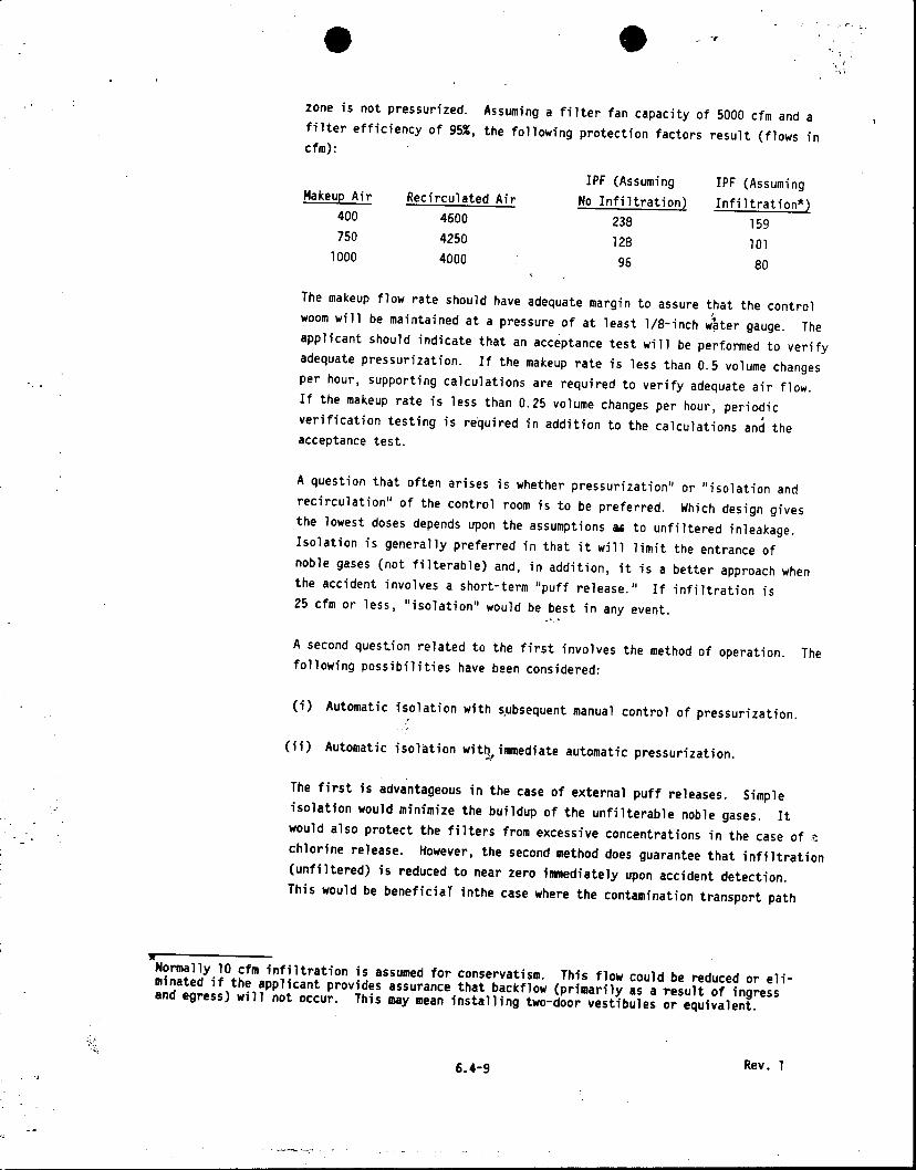
zone is not pressurized. Assuming a filter fan capacity of 5000 cfm and a filter efficiency of 95%, the following protection factors result (flows in cfm):
IPF (Assuming IPF (Assuming Makeup Air Recirculated Air No Infiltration) Infiltration*)
400 4600 238 159 750 4250 128 101
1000 4000 96 80
The makeup flow rate should have adequate margin to assure that the control woom will be maintained at a pressure of at least 1/8-inch water gauge. The applicant should indicate that an acceptance test will be performed to verify adequate pressurization. If the makeup rate is less than 0.5 volume changes per hour, supporting calculations are required to verify adequate air flow. If the makeup rate is less than 0.25 volume changes per hour, periodic verification testing is required in addition to the calculations and the acceptance test.
A question that often arises is whether pressurization" or "isolation and recirculation" of the control room is to be preferred. Which design gives the lowest doses depends upon the assumptions as to unfiltered inleakage. Isolation is generally preferred in that it will limit the entrance of noble gases (not filterable) and, in addition, it is a better approach when the accident involves a short-term "puff release." If infiltration is 25 cfm or less, "isolation" would be best in any event.
A second question related to the first involves the method of operation. The following possibilities have been considered:
(i) Automatic isolation with s.ubsequent manual control of pressurization.
(ii) Automatic isolation with, immediate automatic pressurization.
The first is advantageous in the case of external puff releases. Simple isolation would minimize the buildup of the unfilterable noble gases. It would also protect the filters from excessive concentrations in the case of o chlorine release. However, the second method does guarantee that infiltration (unfiltered) is reduced to near zero immediately upon accident detection. This would be beneficial inthe case where the contamination transport path
Normally 10 cfm infiltration is assumed for conservatism. This flow could be reduced or eliminated if the applicant provides assurance that backflow (primarily as a result of ingress and egress) will not occur. This may mean installing two-door vestibules or equivalent.
6.4-9 Rev. I

to the emergency zone is mainly inside the building. Method (i) should be
used in the case of a toxic gas release and either method (i) or (ii) should
be used in the case of a radiological release, provided Criterion 19 guidelines
can be satisfied. (A substantial time delay should be assumed where manual
isolation is assumed, e.g., 20 minutes for the purposes of dose calculations.)
(4) Dual air inlets for the emergency zone. Several plants have utilized this
concept. The viability of the dual inlet concept depends upon whether or not
the placement of the inlets assures that one inlet will always be free from
contamination. The assurance of a contamination-free inlet depends in part
upon building wake effects, terrain, and the possibility of wind stagnation
or reversal. For example, in a situation where the inlets are glocated at the extreme edges of the plant structures (e.g., one on the north side and one on
the south side), it is possible under certain low probability conditions for
both inlets to be contaminated from the same point source. Reference 7
presents the interim position for dealing with the evaluation of X/Q's,for
dual inlet systems.
With dual inlets placed on plant structures are on opposite sides of
potential radiation release points (e.g, containment building), and are
capable of functioning with an assumed single active failure in the
inlet isolation system, the following considerations may be applied to the
evaluation of the control room X/Q's:
(i) Dual inlet designs without manual or automatic selection control
Equation (6) of Reference 7 may be used with respect to the least
favorable inlet location to estimate X/Q's. The estimated values
can be reduced by a factor of two (2) to account for dilution
effects associated with a dual inlet configuration. This is based
upon the dilution derived from drawing in equal amounts of clean and
contaminated air through two open inlets.
(ii) Dual inlet designs limited to manual selection control - Equation (6)
of Reference 7 may be used with respect to the more favorable inlet
location to estimate the X/Q's. The estimated values can be reduced
by a factor of four (4) to account for dilution effects associated
with a dual inlet configuration and the relative probability that
the operator will make the proper inlet selection. The reduction
factor is contingent upon having redundant radiation detectors within
each air inlet. The reduction factor is based on the judgment that
trained control room operators, in conjunction with radiation alarm
indication, will select and close the contaminated air inlet.
(iii) Dual inlet designs with automatic selection control features
Equation (6) of Reference 7 may be used with respect to the more
Rev. 1 6.4-10

favorable inlet location to estimate the X/Q's. The estimated values can be reduced by about a factor of ten (10) to account for the ability to select a "clean" air inlet. The actual factor may be somewhat higher if the inlet configuration begins to approach the remote air inlet concept such that the probability of having one clean air inlet is relatively high. Plant configuration and meteorological conditions should be used as the principal basis for reduction factors greater than ten (10). The reduction factor of ten (10) or more is contingent upon having redundant radiation detectors in each inlet and the provisions of acceptable control logic which would be used in the automatic selection of a clean air inlet.
Because damage to the ducting might seriously affect the system capability to protect the operators, the ducting should be seismic Category I and should be protected against tornado missiles. In addition, the number and placement of dampers must be such as to assure both flow and isolationin each inlet assuming one single active component failure. (See Appe6dix A for information on the damper repair alternative.) The location of the intakes with respect to the plant security fence should also be reviewed.
(5) Bottled air supply for a limited time. In some plant designs the containment pressure is reduced below atmospheric within one hour after a DBA. This generally assures that after one hour significant radioactive material will not be released from the containment. Such a design makes it feasible to maintain the control room above atmospheric pressure by use of bottled air. Periodic pressurization tests are required to determine that the rated flow (normally about 300 to 600 cfm) is sufficient to pressurize the control room to at least 1/8-inch water gauge. The system is also required to be composed of several separate circuits (one of which is assumed to be inoperative to account for a possible single failure). At least one (nonredundant) oncethrough filter system for pressurization as a standby for accidents of long duration is also desirable.
Compressed air bottles should be protected from tornado missiles or internallygenerated missiles and should be placed so as not to cause damage to vital equipment or interference with operation if they fail.
4. Emergency Standby Filters Refer to Standard Review Plan 6.5.1.
5. Relative Location of Source and Control Room This review area involves identification of all potential sources of toxic, radioactive, or otherwise potentially hazardous gases and analysis of their transport to the control room. There are three basic categories: DBA radioactive sources, toxic gases such as
6.4-11 Rev. 1

chlorine, and gases with the potential for being released inside confined areas adjacent
to the control room.
a. DBA Radioactive Sources
The LOCA source terms determined in Appendix A to Standard Review Plan 15.6.5
review are referred to and routinely used to evaluate radiation levels external
to the control room. The dispersal from the containment or the standby gas
treatment vent is determined with a building wake diffusion model. This model
is discussed in Reference 7. Other DBAs are reviewed to determine whether they
might constitute a more severe hazard than the LOCA. If this is suspected, an
additional analysis is performed for the suspect DBAs. The HMB provides the
meteorological input and reviews the AAB calculation of X/Q values,.
b. Toxic Gases
The applicant is asked to identify those toxic substances stored (or transported)
on or in the vicinity of the site which may pose a threat to the reactor,oper
ators by producing toxic gases upon accidental release. The method used to
determine whether the quantity or location of the toxic material is such as to
require closer study is described in Regulatory Guide 1.78 (Ref. 3). This
guide also discusses the methods for analyzing the degree of risk and states, in
general terms, the various protective measures that could be instituted if the
hazard is found to be too great. In the case of chlorine, specific acceptable
protective provisions have been determined; these are described in detail in
Reference 4.
In summary, the following provisions or their equivalent are required (pertaining
to the emergency zone ventilation system):
(1) Quick-acting toxic gas detectors.
(2) Automatic emergency zone isolation.
(3) Emergency zone leaktightness.'
(4) Limited fresh air makeup rates.
(5) Breathing apparatus and associated bottled air supply.
(Note that the best solution for a particular case will depend on the toxic gas in
question and on the specific ventilation system design.)
c. Confined Area Releases
The reviewer studies the control building layout in relation to potential sources
inside the control building or adjacent connected buildings. The following concerns are checked:
Rev. 1 6.4-12

(1) Storage locations of CO2 or other firefighting materials should be such as to eliminate the possibility of significant quantities of the gases entering the emergency zone. (The ASB has the primary responsibility in this area.)
(2) The ventilation zones adjacent to the emergency zone should be configured and balanced to preclude air flow toward the emergency zone.
(3) All pressurized equipment and piping (e.g., main steam lines and turbines) that could cause significant pressure gradients when failed inside buildings should be isolated from the emergency zone by multiple barriers such as multiple door vestibules or their equivalent.
6. Radiation Shielding
Control room operators as well as other plant personnel are protected from radiation sources associated with a normally operating plant by various combinations of shielding and distance. The adequacy of this type of protection for normal operating conditions is reviewed and evaluated by the RAB. To a large extent the same radiation shielding (and missile barriers) also provides protection from design basis accident radiation sources. This is especially true with respect to the control room walls which usually consist of at least 18 inches of concrete. In most cases, the radiation coming from external design basis accident radiation sources is attenuated to negligible levels. However, the following items should be considered qualitatively in assessing the adequacy of control room radiation shielding:
a. Control room structure boundary. Wall, ceiling, and floor materials and thickness should be reviewed. Eighteen inches to two feet of concrete or its equivalent will be adequate in most cases.
b. Radiation streaming. -The control room structure boundary should be reviewed with respect to penetrations (e.g., doors, ducts, stairways, etc.). The potential for radiation streaming from accident sources should be identified, and if deemed necessary, quantitatively evaluated. Support from the RAB may be required for some radiation streaming dose calculations.
c. Radiation shielding from internal sources. If sources internal to the control room complex are identified, radiation shielding against them should be reviewed. Typical sources in this category include contaminated filter trains, or airborne radioactivity in enclosures adjacent to the control room.
Evaluations of radiation shielding effectiveness with respect to the above items should be performed using simplified analytical models for point, line, or volume sources such as those presented in References 10 and 11. If more extended analysis is required, analytical support from the RAB should be requested. The applicant's coverage of the above items should also be reviewed in terms of completeness, method of analysis, and assumptions.
6.4-13 Rev. I

7. Independent Analyses
a. Control Room Doses
Although the applicant is required to calculate doses to the control room
operators, independent analyses are made by the AAB because of the diversity of
control room habitability system designs and the engineering judgment involved
in their evaluation. Using the approach indicated in Reference 7, the source
terms and doses due to a DBA are calculated. The source terms determined by the
AAB's independent analysis of LPZ doses for a LOCA are used. The methods and
assumptions for this calculation are presented in Appendix A to Standard Review
Plan 15.6.5. The control room doses are determined by estimating the X/Q from
the source points to the emergency zone using meteorological input supplied by
the HMB, by determining the credit for the emergency zone's protection features,
and by calculating the dose. Figure 6.4-1 shows a form which may be used to
summarize the information that is needed for the control room dose calculation.
The effective X/Q's are used for calculating the doses. The dose is then
compared with the guidelines of General Design Criterion 19. If the guidelines
are exceeded, the applicant is asked to improve the system. In the event that
other DBAs are expected to result in doses comparable to or higher than the
LOCA, additional analyses are performed. The limiting accidents are compared
with Criterion 19.
b. Other Analyses
Special case analyses are performed when questions are raised about certain poten
tial sources of toxic or radioactive gases. The methods used in these analyses
conform to current DBA methods concerning dispersion and dose calculations.
Regulatory Guide 1.78 should be consulted by the site analyst to see if nearby
facilities could present a potential hazard that requires detailed analysis.
IV. EVALUATION FINDINGS
The reviewer verifies that sufficient information has been provided and that the review
and calculations support conclusions of the following type, to be included in the staff's
safety evaluation report:
1. If the plant meets Criterion 19, the following statement or its equivalent is made:
"The applicant proposes to meet General Design Criterion 19 of Appendix A to 10 CFR
Part 50 by use of concrete shielding and by installing redundant __ cfm
recirculating charcoal filters in the control room ventilation system. These
filters will be automatically activated upon an accident signal, high radiation
signal, or high chlorine signal. Independent calculations of the potential
radiation doses to control room personnel following a LOCA show the resultant
doses to be within the guidelines of Criterion 19."
Rev. 1 6.4-14

2. If the design is not adequate, the fact is stated. Alternatives such as an increase in the charcoal filter flow rate may be indicated as is given in the example below:
"The staff has calculated the potential radiation doses to control room personnel following a LOCA. The resultant whole body doses are within the guidelines of Criterion 19. The thyroid dose resulting from exposure to radioactive iodine exceeds the dose guidelines. The applicant will be required to commit to increasing the filtration system size from 2000 cfm to 4000 cfm. This increased filtration will be sufficient to keep the estimated thyroid doses within the guidelines."
3. If special protection provisions for toxic gases are not required, the following statement or its equivalent is made:
"The habitability of the control room was evaluated using the procedures described in Regulatory Guide 1.78. As indicated in Section 2.2, no offsite storage or transport of chemicals is close enough to the plant to be considered a hazard. There are no onsite chemicals that can be considered hazardous under Regulatory Guide 1.78. A sodium hypochlorite biocide system will be used, thus eliminating an onsite chlorine hazard. Therefore, special provisions for protection against toxic gases will not be required. Self-contained breathing apparatus is provided for the emergency crew to provide assurance of control room habitability in the event of occurrences such as smoke hazards."
4. If special protection provisions are required, compliance or noncompliance with the guidelines of Regulatory Guides 1.78 and 1.95 should be stated.
V. REFERENCES
1. 10 CFR Part 50, Appendix-A, General Design Criterion 19, "Control Room."
2. Regulatory Guide 1.52, "Design, Testing, and Maintenance Criteria for EngineeredSafety-Feature Atmosphere Cleanup System Air Filtration and Adsorption Units of Light-Water-Cooled Nuclear Power Plants."
3. Regulatory Guide 1.78, "Assumptions for Evaluating the Habitability of a Nuclear Power Plant Control Room During a Postulated Hazardous Chemical Release."
4. Draft Regulatory Guide 1.95, "Protection of Nuclear Power Plant Control Room Operators Against an Accidental Chlorine Release."
.5. Draft Regulatory Guide 8.X, "Acceptable Programs for Respiratory Protection."
6. "Manual of Respiratory Protection Against Airborne Radioactive Material," WASH-1287, U.S. Atomic Energy Commission (1974).
Rev. 1 6.4-15

0 + 7. K.G. Murphy and K.M. Campe, "Nuclear Power Plant Control Room Ventilation System
Design for Meeting General Design Criterion 19," 13th AEC Air Cleaning Conference, August 1974.
8. "Leakage Characteristics of Openings for Reactor Housing Components," NAA-SR-MEMO-5137, Atomics International, Div. of North American Aviation, Inc., June 20, 1960.
9. R.L. Koontz, et al., "Leakage Characteristics of Conventional Building Components for Reactor Housing Construction," Trans. Am. Nucl. Soc., November 1961.
10. R.G. Jaeger, et al., eds., "Engineering Compendium on Radiation Shielding, Vol. 1, "Shielding Fundamentals and Methods," Springer-Verlag (1968).
11. N.M. Schaeffer, "Reactor Shielding for Nuclear Engineers," TID-75951, U.S. Atomic Energy Commission.
Rev. 1 6.4-19

SECTION 6.4 APPENDIX A
ACCEPTANCE CRITERIA FOR VALVE OR DAMPER REPAIR ALTERNATIVE
The control roomventilation system must meet the criterion that it work properly even with a single failure of an active component. In certain cases, complex valve or damper configurations are required to meet the single failure criterion. For example, assurance of the isolation and operability of each leg of a dual inlet system at various times after a postulated accident could require a four-valve arrangement in which two pairs of series valves are connected in parallel. The mechnical, power, and control components of such arrangements combine to form a rather complex system. Credit will be allowed for an alternative system that allowed the failed valve to be manually repositioned so that it will not interfere with the operation of the system. For example, in the case of a dual inlet system, if credit for repair is given, then two valves in series in each leg of the dual inlet would be acceptable. Where a valve fails closed but meets the criteria given below, credit would be allowed for the valve to be repositioned and locked in an open position.
The approval of the repair option is contingent upon the intrinsic reliability of the internal components of the valve or damper and also upon the ease and ability to overcome the failure of the external actuating components (electrical relays, motors, hydraulic pistons, etc.). The following criteria or their equivalent will be required;
1. The valve or damper components must be listed as to which are considered internal (nonrepairable) and which dxternal (repairable). These must be designed to meet the following criteria.
a. Internal valve components (components that are difficult to repair manually without opening the ductwork) must ,be judged to have a very low probability of failure. The component design details will be revfewed and characteristics such as simplicity, ruggedness, and suspectibility to postulated failure mechanisms will be considered in arriving at an engineered judgment of the acceptability of the internal component design with respect to reliability. For example, a butterfly valve welded or keyed onto a pivot shaft would be considered a high reliability internal component. Conversely, multiple-blade dampers, actuated by multi-element linkages or pneumatically-operated components internal to the ducts, would be viewed as being subject to failure.
b. External valve components (components including motors and power supplies that are to be assumed repairable or removable) must be designed to ensure that the failed valve component can be bypassed easily and safely and that the valve can be manipulated into an acceptable position. The electronic components must be isolated from other equipment to assure that the repair operations do not result in further equipment failure.
6.4-17 Rev. 1

2. The location and positioning of the valve or damper must permit easy access from the
control room for convenient repair, especially under applicable DBA conditions.
3. Appropriate control room instrumentation should be provided for a clear indication and annunciation of valve or damper malfunction.
4. Periodic manipulation of the valve or damper by control room operators should be required for training purposes and to verify proper manual operability of the valve or damper.
5. The need for manual manipulations of the failed valve or damper should not be recurrent during the course of the accident. Manipulation should not occur more than once during the accident. Adjustment or realignment of other parts of the system shoulh be possible from the control room with the failed valve in a fixed position.
6. The time for repair used in the computation of control room exposures should be taken as the time necessary to repair the valve plus a one-half hour margin. No manual correction
will be credited during the first two hours of the accident.
7. Compliance with the above criteria should be documented in the SAR whenever the repair option is used.
Rev. 1 6.4-18

FIGURE 6.4-1 Summary Sheet for Control Room Dose Analysis
MEMORANDUM TO: (Site Analyst) (Meteorologist)
cc: L. Hulman R.W. Houston (Habitability File)
CONCERNING CONTROL ROOM DOSE ANALYSIS FOR
The following summarizes the X/Q's used in determining the control room operator dose for the subject plant:
VENTILATION SYSTEM DESCRIPTION
SKETCH OF SYSTEM (and inlets/sources if applicable)
SUMMATION OF X/Q ANALYSIS
Source/Receptor Type and Distance
S/D Ratio K Factor
Number of 22 1/20 Wind Direction Sectors that Result in Exposure
Central Wind Sector (sector wind is blowing from)
5% Wind Speed (m/sec) __*40% Wind Speed (m/sec) 2 3 Projected Area of Wake (m2) 5% X/Q (sec/m3
Time Wind Speed Factor Wind*Direction Factor Occupancy Factor Effective X/Q's
0-8 hr 1 1 1 8-24 hr 1 1-4 day 0.6 4-30 day 0.4
ACTION REQUESTED
Site Analyst
- For your information only - Please use the effective X/Q's in TACT run and provide control room doses. In addi
tion, please summarize safety system assumptions and indicate their status (interim or final).
Meteorologist
- These are interim X/Q's. Please review to determine their reasonableness. - These are final X/Q's. Please determine if they are accurate based on your analysis of site data.
Please Contact
6.4-19 Rev. 1