Embed Size (px)
Citation preview
OIL INDIA LIMITED
(A Government of India Enterprises)
4, India Exchange Place
Kolkata -1
TELEPHONE NO. (033) 22301657
FAX NO: (033) 22302596
Email: [email protected]
FORWARDING LETTER
Tender No & Date : SKI9254P16 Date: 16.11.2015
Tender Fee : Rs 1,000.00
Bid Security Amount : Rs 2,47,500.00
Bidding Type : Single Stage Two Bid
Bid Closing on : As mentioned in the Basic Data of e-portal
Bid Opening on : As mentioned in the Basic Data of e-portal
Performance Guarantee : Applicable
Integrity Pact : Applicable
Delivery Required : At DULIAJAN, ASSAM
OIL invites Bids for Supply, fabrication, installation & commissioning of Multipurpose Fire
Tender – 2 Nos. as per Annexure II through its E-Procurement site. The bidding documents and
other terms and conditions are available at Booklet No. MM/CALCUTTA/E-01/2010. The
prescribed Bid Forms for submission of bids are available in the Technical RFx -> External Area -
> Tender Documents.
The general details of tender can be viewed by opening the RFx [ Tender] under RFx and
Auctions. The details of items tendered can be found in the Item Data and details uploaded under
Technical RFX.
The tender is invited with firm price for the specified quantity. Further details of tender are given
below:-
1. Gist of Item with Quantity and Unit of measure are as under:
- 2 -
SL.NO.
MATERIAL DESCRIPTION. QUANTITY
UNIT
10
------------ 0C000198
Supply, fabrication, installation &
commissioning of Multipurpose Fire Tender
[Details are as per Annexure II]
2 NOS.
The tender will be governed by:
a) “General Terms & Conditions” for e-Procurement as per Booklet NO. MM/CALCUTTA/E-
01/2010 for E-procurement (LCB Tenders).
b) Technical specifications with BEC/BRC and Qty. as per ANNEXURE II .
c) The prescribed Bid Forms for submission of bids are available in the Technical RFx ->
External Area - > Tender Documents.
d) In the event of receipt of only a single offer against the tender within B.C. date, OIL reserves
the right to extend the B.C. date as deemed fit by the Company. During the extended period,
the bidders who have already submitted the bids on or before the original B.C. date, shall not
be permitted to revise their quotation.
e) Any sum of money due and payable to the contractor (including Security Deposit
refundable to them) under this or any other contract may be appropriated by Oil India
Limited and set-off against any claim of Oil India Limited (or such other person or persons
contracting through Oil India Limited) for payment of sum of money arising out of this
contract or under any other contract made by the contractor with Oil India Limited (or such
other person or persons contracting through Oil India Limited).
f) Bidder are advised to fill up the Technical bid CHECK LIST and RESPONSE SHEET
given in MS excel format in Technical RFx -> External Area - > Tender Documents. The
above filled up document to be uploaded in the Technical RFX Response.
g) Integrity Pact : OIL shall be entering into an Integrity Pact with the bidders as per format enclosed vide Annexure V of the tender document. This Integrity Pact proforma has been duly signed digitally by OIL’s competent signatory. The proforma has to be returned by the bidder (along with the technical bid) duly signed (digitally) by the same signatory who signed the bid, i.e. who is duly authorized to sign the bid. Any bid not accompanied by Integrity Pact Proforma duly signed (digitally) by the bidder shall be rejected straightway. Uploading the Integrity Pact with digital signature will be construed that all pages of the Integrity Pact has been signed by the bidder’s authorized signatory who sign the Bid.
The name of the OIL's Independent External Monitor at present are as under: 1. SHRI RAJIV MATHUR, IPS(Retd.), e-Mail ID : [email protected]
Special Note:
- 3 -
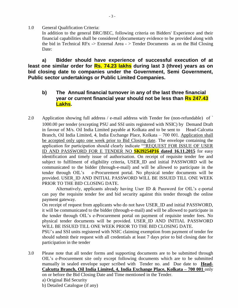
1.0 General Qualification Criteria:
In addition to the general BRC/BEC, following criteria on Bidders' Experience and their
financial capabilities shall be considered (documentary evidence to be provided along with
the bid in Technical RFx -> External Area - > Tender Documents as on the Bid Closing
Date:
a) Bidder should have experience of successful execution of at least one similar order for Rs. 74.23 lakhs during last 3 (three) years as on bid closing date to companies under the Government, Semi Government, Public sector undertakings or Public Limited Companies.
b) The Annual financial turnover in any of the last three financial year or current financial year should not be less than Rs 247.43 Lakhs.
2.0 Application showing full address / e-mail address with Tender fee (non-refundable) of `
1000.00 per tender (excepting PSU and SSI units registered with NSIC) by Demand Draft
in favour of M/s. Oil India Limited payable at Kolkata and to be sent to Head-Calcutta
Branch, Oil India Limited, 4, India Exchange Place, Kolkata – 700 001. Application shall
be accepted only upto one week prior to Bid Closing date. The envelope containing the
application for participation should clearly indicate ““REQUEST FOR ISSUE OF USER
ID AND PASSWORD FOR E TENDER NO SKI9254P16 dated 16.11.2015 for easy
identification and timely issue of authorisation. On receipt of requisite tender fee and
subject to fulfilment of eligibility criteria, USER_ID and initial PASSWORD will be
communicated to the bidder (through-e-mail) and will be allowed to participate in the
tender through OIL’s e-Procurement portal. No physical tender documents will be
provided. USER_ID AND INITIAL PASSWORD WILL BE ISSUED TILL ONE WEEK
PRIOR TO THE BID CLOSING DATE.
Alternatively, applicants already having User ID & Password for OIL’s e-portal
can pay the requisite tender fee and bid security against this tender through the online
payment gateway.
On receipt of request from applicants who do not have USER_ID and initial PASSWORD,
it will be communicated to the bidder (through-e-mail) and will be allowed to participate in
the tender through OIL’s e-Procurement portal on payment of requisite tender fees. No
physical tender documents will be provided. USER_ID AND INITIAL PASSWORD
WILL BE ISSUED TILL ONE WEEK PRIOR TO THE BID CLOSING DATE.
PSU’s and SSI units registered with NSIC claiming exemption from payment of tender fee
should submit their request with all credentials at least 7 days prior to bid closing date for
participation in the tender
3.0 Please note that all tender forms and supporting documents are to be submitted through
OIL’s e-Procurement site only except following documents which are to be submitted
manually in sealed envelope super scribed with Tender no. and Due date to Head-
Calcutta Branch, Oil India Limited, 4, India Exchange Place, Kolkata – 700 001 only
on or before the Bid Closing Date and Time mentioned in the Tender.
a) Original Bid Security
b) Detailed Catalogue (if any)
- 4 -
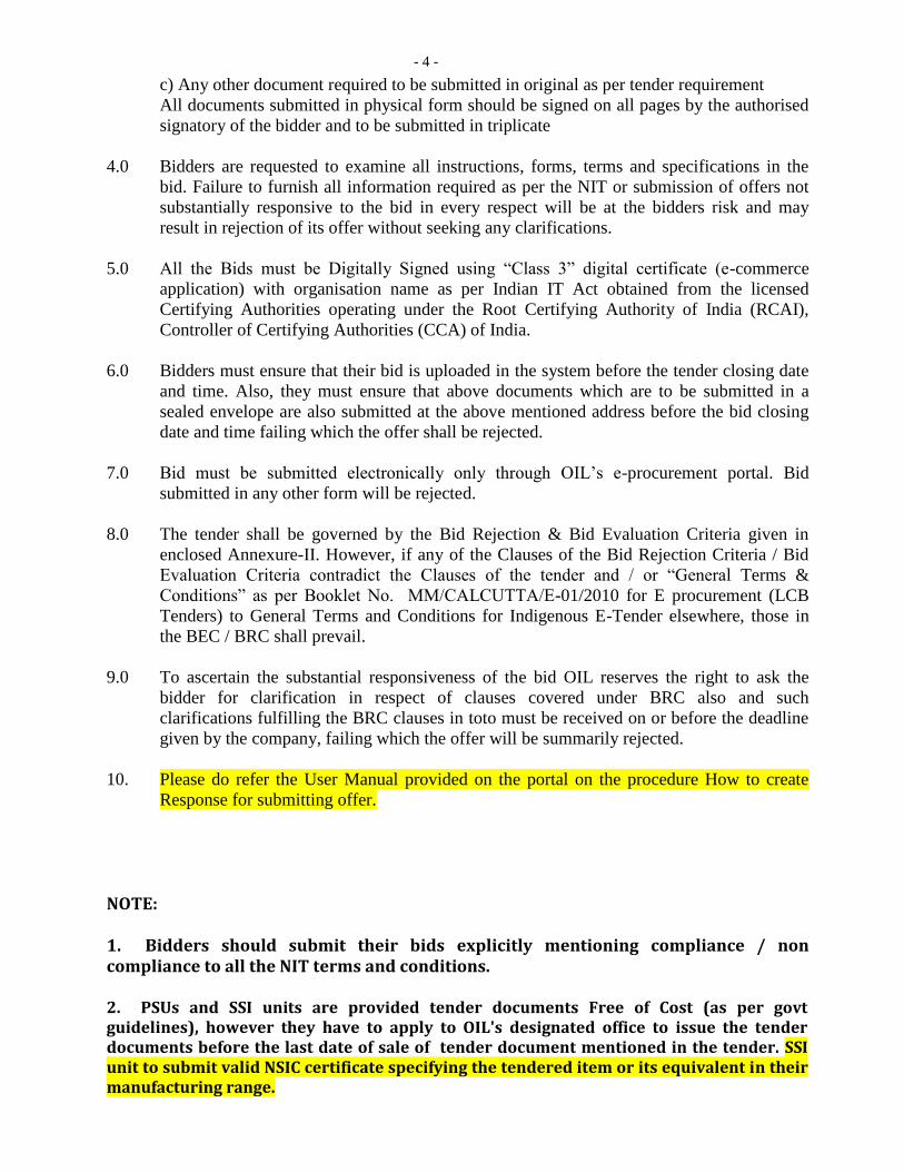
c) Any other document required to be submitted in original as per tender requirement
All documents submitted in physical form should be signed on all pages by the authorised
signatory of the bidder and to be submitted in triplicate
4.0 Bidders are requested to examine all instructions, forms, terms and specifications in the
bid. Failure to furnish all information required as per the NIT or submission of offers not
substantially responsive to the bid in every respect will be at the bidders risk and may
result in rejection of its offer without seeking any clarifications.
5.0 All the Bids must be Digitally Signed using “Class 3” digital certificate (e-commerce
application) with organisation name as per Indian IT Act obtained from the licensed
Certifying Authorities operating under the Root Certifying Authority of India (RCAI),
Controller of Certifying Authorities (CCA) of India.
6.0 Bidders must ensure that their bid is uploaded in the system before the tender closing date
and time. Also, they must ensure that above documents which are to be submitted in a
sealed envelope are also submitted at the above mentioned address before the bid closing
date and time failing which the offer shall be rejected.
7.0 Bid must be submitted electronically only through OIL’s e-procurement portal. Bid
submitted in any other form will be rejected.
8.0 The tender shall be governed by the Bid Rejection & Bid Evaluation Criteria given in
enclosed Annexure-II. However, if any of the Clauses of the Bid Rejection Criteria / Bid
Evaluation Criteria contradict the Clauses of the tender and / or “General Terms &
Conditions” as per Booklet No. MM/CALCUTTA/E-01/2010 for E procurement (LCB
Tenders) to General Terms and Conditions for Indigenous E-Tender elsewhere, those in
the BEC / BRC shall prevail.
9.0 To ascertain the substantial responsiveness of the bid OIL reserves the right to ask the
bidder for clarification in respect of clauses covered under BRC also and such
clarifications fulfilling the BRC clauses in toto must be received on or before the deadline
given by the company, failing which the offer will be summarily rejected.
10. Please do refer the User Manual provided on the portal on the procedure How to create
Response for submitting offer.
NOTE: 1. Bidders should submit their bids explicitly mentioning compliance / non compliance to all the NIT terms and conditions. 2. PSUs and SSI units are provided tender documents Free of Cost (as per govt guidelines), however they have to apply to OIL's designated office to issue the tender documents before the last date of sale of tender document mentioned in the tender. SSI unit to submit valid NSIC certificate specifying the tendered item or its equivalent in their manufacturing range.
- 5 -
3. Bids are invited under Single Stage TWO Bid System. Bidders shall quote accordingly under Single Stage TWO Bid System.
Yours Faithfully,
Sd-
(G. C. Sarma)
SMM(P) For Head-Calcutta Branch
- 6 -
OIL INDIA LIMITED
(A Government of India Enterprise)
4, India Exchange Place, 4th
floor,
Kolkata 700001,
West Bengal (India)
TELEPHONE NO. (033) 2230 1657 / 58 / 59
FAX NO: (033) 2230 2596
Email : [email protected]
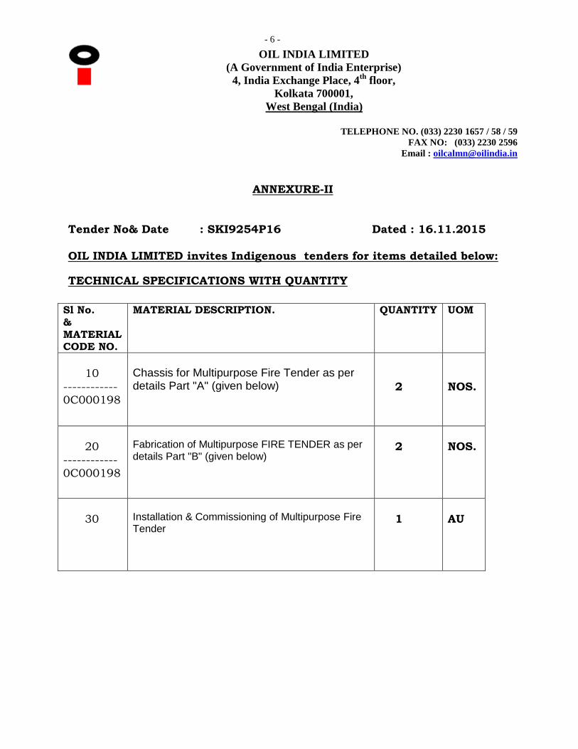
ANNEXURE-II
Tender No& Date : SKI9254P16 Dated : 16.11.2015
OIL INDIA LIMITED invites Indigenous tenders for items detailed below:
TECHNICAL SPECIFICATIONS WITH QUANTITY
Sl No. & MATERIAL CODE NO.
MATERIAL DESCRIPTION. QUANTITY UOM
10
------------ 0C000198
Chassis for Multipurpose Fire Tender as per details Part "A" (given below)
2
NOS.
20
------------ 0C000198
Fabrication of Multipurpose FIRE TENDER as per details Part "B" (given below)
2
NOS.
30
Installation & Commissioning of Multipurpose Fire Tender
1
AU

- 7 -
Special Terms & Conditions : Buy Back of Old Fire Tenders - OIL - 8022 & 8023 1.0 The old Fire Tender – OIL - 8022 & 8023, (without Foam Compound & Equipment) will be offered to the successful L-1 bidder along with buy back offer. Actual condition of the vehicle can be assessed by the bidder at OIL’s site at Duliajan on their own cost. The Party shall make all efforts to take away both vehicles from OIL’s site at Duliajan and the necessary registration book/document along with necessary "NO OBJECTION CERTIFICATE" would be given to successful bidder by OIL. All required formalities with RTO/other applicable authorities shall be done by the Party only. The old Fire Tender will be handed over to the party after commissioning of the new Multi-Purpose Fire Tender. 2.0 The details of old Fire Tenders, OIL - 8022 & 8023 are as given below: Chassis Model : TATA 1613/42 Year of Commissioning : 2003 Foam Tank Capacity : 1350 Ltrs. Water Tank Capacity : 2250 Ltrs. Centrifugal Pump : 2250 LPM @ 7 Kg/cm2 3.0 The Fire Tenders shall be offered on "AS IS WHERE IS" basis at the time of final buy-back of the said items by the successful bidder.
PART – “A” CHASSIS FOR “MULTIPURPOSE FIRE TENDER”
Brand new 4x2 drive Truck chassis of TATA, Ashok Leyland or Equivalent make manufactured not prior to six months from the date of issuance of Letter of Intent (LOI). The bidder shall take special care in selecting and designing the Multi-Purpose Fire Tender considering the unit’s application in rough terrain and typical oilfield roads. The offered model shall be latest and conforming to international quality standard norms, having specifications, fittings, accessories, etc. as under:
1. CHASSIS:
a Drive &Cowl 4 x 2 Drive & Full Forward Control Cowl.
b Engine Min. 6 cylinder Water-cooled diesel engine.
c Max. Output Power Not less than 160 HP at rated rpm.
d Max. Output Torque Not less than 400NM at rated rpm.
e Emission Euro-III/BS-III or as applicable in the state of Assam at the time of delivery of the vehicle.
f Steering Hydraulic Power Assisted Steering (Right Hand Steering).
g Gearbox Minimum 5 forward speed & 1 reverse speed.
h PTO(as applicable) Side PTO (Chassis should be attached with PTO) for driving the Hi Pressure Pump. It should be suitable to match engine and
- 8 -
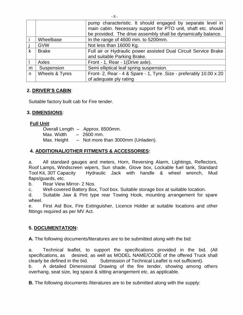
pump characteristic. It should engaged by separate level in main cabin. Necessary support for PTO unit, shaft etc. should be provided. The drive assembly shall be dynamically balance.
i Wheelbase In the range of 4600 mm. to 5200mm.
j GVW Not less than 16000 Kg.
k Brake Full air or Hydraulic power assisted Dual Circuit Service Brake and suitable Parking Brake.
l Axles Front - 1, Rear - 1(Drive axle).
m Suspension Semi elliptical leaf spring suspension.
n Wheels & Tyres Front- 2, Rear - 4 & Spare - 1, Tyre .Size - preferably 10.00 x 20 of adequate ply rating
2. DRIVER’S CABIN: Suitable factory built cab for Fire tender.
3. DIMENSIONS: Full Unit:
Overall Length – Approx. 8500mm. Max. Width – 2600 mm. Max. Height – Not more than 3000mm (Unladen). 4. ADDITIONAL/OTHER FITMENTS & ACCESSORIES: a. All standard gauges and meters, Horn, Reversing Alarm, Lightings, Reflectors, Roof Lamps, Windscreen wipers, Sun shade, Glove box, Lockable fuel tank, Standard Tool Kit, 30T Capacity Hydraulic Jack with handle & wheel wrench, Mud flaps/guards, etc. b. Rear View Mirror- 2 Nos. c. Well-covered Battery Box, Tool box. Suitable storage box at suitable location. d. Suitable Jaw & Pint type rear Towing Hook, mounting arrangement for spare wheel. e. First Aid Box, Fire Extinguisher, Licence Holder at suitable locations and other fittings required as per MV Act. 5. DOCUMENTATION: A. The following documents/literatures are to be submitted along with the bid: a. Technical leaflet, to support the specifications provided in the bid. (All specifications, as desired, as well as MODEL NAME/CODE of the offered Truck shall clearly be defined in the bid. Submission of Technical Leaflet is not sufficient). b. A detailed Dimensional Drawing of the fire tender, showing among others overhang, seat size, leg space & sitting arrangement etc. as applicable. B. The following documents /literatures are to be submitted along with the supply:
- 9 -
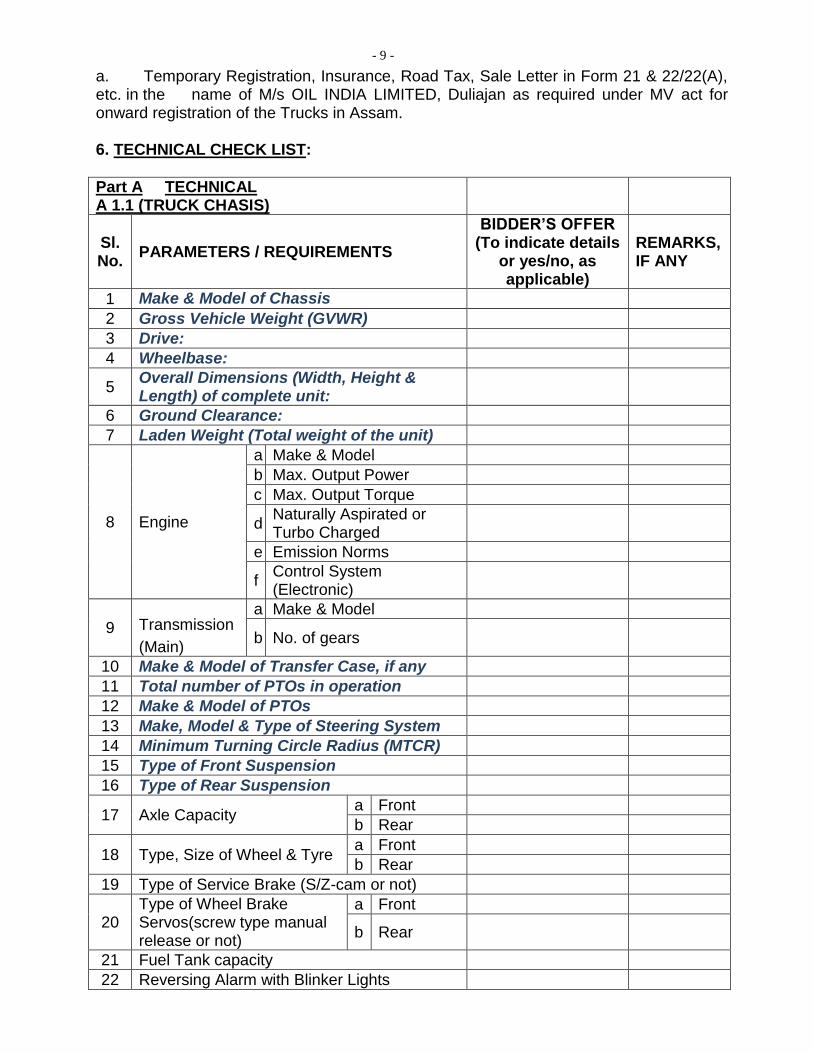
a. Temporary Registration, Insurance, Road Tax, Sale Letter in Form 21 & 22/22(A), etc. in the name of M/s OIL INDIA LIMITED, Duliajan as required under MV act for onward registration of the Trucks in Assam. 6. TECHNICAL CHECK LIST:
Part A TECHNICAL A 1.1 (TRUCK CHASIS)
Sl. No.
PARAMETERS / REQUIREMENTS
BIDDER’S OFFER (To indicate details
or yes/no, as applicable)
REMARKS, IF ANY
1 Make & Model of Chassis
2 Gross Vehicle Weight (GVWR)
3 Drive:
4 Wheelbase:
5 Overall Dimensions (Width, Height & Length) of complete unit:
6 Ground Clearance:
7 Laden Weight (Total weight of the unit)
8 Engine
a Make & Model
b Max. Output Power
c Max. Output Torque
d Naturally Aspirated or Turbo Charged
e Emission Norms
f Control System (Electronic)
9 Transmission
(Main)
a Make & Model
b No. of gears
10 Make & Model of Transfer Case, if any
11 Total number of PTOs in operation
12 Make & Model of PTOs
13 Make, Model & Type of Steering System
14 Minimum Turning Circle Radius (MTCR)
15 Type of Front Suspension
16 Type of Rear Suspension
17 Axle Capacity a Front
b Rear
18 Type, Size of Wheel & Tyre a Front
b Rear
19 Type of Service Brake (S/Z-cam or not)
20 Type of Wheel Brake Servos(screw type manual release or not)
a Front
b Rear
21 Fuel Tank capacity
22 Reversing Alarm with Blinker Lights
- 10 -
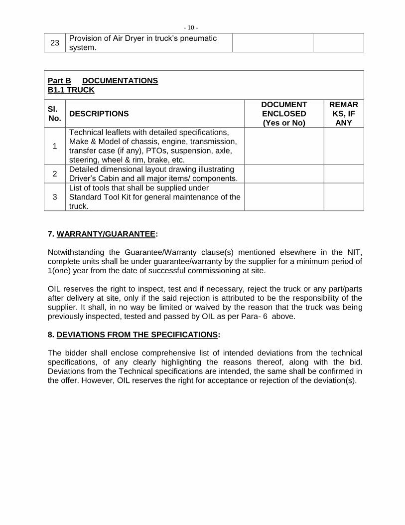
23 Provision of Air Dryer in truck’s pneumatic system.
Part B DOCUMENTATIONS B1.1 TRUCK
Sl. No.
DESCRIPTIONS DOCUMENT ENCLOSED (Yes or No)
REMARKS, IF ANY
1
Technical leaflets with detailed specifications, Make & Model of chassis, engine, transmission, transfer case (if any), PTOs, suspension, axle, steering, wheel & rim, brake, etc.
2 Detailed dimensional layout drawing illustrating Driver’s Cabin and all major items/ components.
3 List of tools that shall be supplied under Standard Tool Kit for general maintenance of the truck.
7. WARRANTY/GUARANTEE: Notwithstanding the Guarantee/Warranty clause(s) mentioned elsewhere in the NIT, complete units shall be under guarantee/warranty by the supplier for a minimum period of 1(one) year from the date of successful commissioning at site. OIL reserves the right to inspect, test and if necessary, reject the truck or any part/parts after delivery at site, only if the said rejection is attributed to be the responsibility of the supplier. It shall, in no way be limited or waived by the reason that the truck was being previously inspected, tested and passed by OIL as per Para- 6 above. 8. DEVIATIONS FROM THE SPECIFICATIONS: The bidder shall enclose comprehensive list of intended deviations from the technical specifications, of any clearly highlighting the reasons thereof, along with the bid. Deviations from the Technical specifications are intended, the same shall be confirmed in the offer. However, OIL reserves the right for acceptance or rejection of the deviation(s).
- 11 -
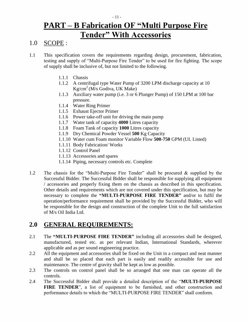
PART – B Fabrication OF “Multi Purpose Fire
Tender” With Accessories 1.0 SCOPE :
1.1 This specification covers the requirements regarding design, procurement, fabrication,
testing and supply of “Multi-Purpose Fire Tender” to be used for fire fighting. The scope
of supply shall be inclusive of, but not limited to the following.
1.1.1 Chassis
1.1.2 A centrifugal type Water Pump of 3200 LPM discharge capacity at 10
Kg/cm2
(M/s Godiva, UK Make)
1.1.3 Auxiliary water pump (i.e. 3 or 6 Plunger Pump) of 150 LPM at 100 bar
pressure.
1.1.4 Water Ring Primer
1.1.5 Exhaust Ejector Primer
1.1.6 Power take-off unit for driving the main pump
1.1.7 Water tank of capacity 4000 Litres capacity
1.1.8 Foam Tank of capacity 1000 Litres capacity
1.1.9 Dry Chemical Powder Vessel 500 Kg Capacity
1.1.10 Water cum Foam monitor Variable Flow 500-750 GPM (UL Listed)
1.1.11 Body Fabrication/ Works
1.1.12 Control Panel
1.1.13 Accessories and spares
1.1.14 Piping, necessary controls etc. Complete
1.2 The chassis for the “Multi-Purpose Fire Tender” shall be procured & supplied by the
Successful Bidder. The Successful Bidder shall be responsible for supplying all equipment
/ accessories and properly fixing them on the chassis as described in this specification.
Other details and requirements which are not covered under this specification, but may be
necessary to complete the “MULTI-PURPOSE FIRE TENDER” and/or to fulfil the
operation/performance requirement shall be provided by the Successful Bidder, who will
be responsible for the design and construction of the complete Unit to the full satisfaction
of M/s Oil India Ltd.
2.0 GENERAL REQUIREMENTS:
2.1 The “MULTI-PURPOSE FIRE TENDER” including all accessories shall be designed,
manufactured, tested etc. as per relevant Indian, International Standards, wherever
applicable and as per sound engineering practice.
2.2 All the equipment and accessories shall be fixed on the Unit in a compact and neat manner
and shall be so placed that each part is easily and readily accessible for use and
maintenance. The centre of gravity shall be kept as low as possible.
2.3 The controls on control panel shall be so arranged that one man can operate all the
controls.
2.4 The Successful Bidder shall provide a detailed description of the “MULTI-PURPOSE
FIRE TENDER”, a list of equipment to be furnished, and other construction and
performance details to which the “MULTI-PURPOSE FIRE TENDER” shall conform.
- 12 -
2.5 The detailed description of the “MULTI-PURPOSE FIRE TENDER” shall include, but
shall not be limited to, estimated weight, wheelbase, turning clearance radius, principal
dimensions, transmission, and axle ratios.
2.6 Responsibility for the “MULTI-PURPOSE FIRE TENDER” and equipment shall remain
with the Successful Bidder until they are accepted by the OIL.
2.7 On initial delivery of the “MULTI-PURPOSE FIRE TENDER”, the Successful Bidder
shall supply a qualified representative to demonstrate the “MULTI-PURPOSE FIRE
TENDER” and provide initial instructions to representatives of the OIL regarding the
operation, care, and maintenance of the “MULTI-PURPOSE FIRE TENDER” and
equipment supplied.
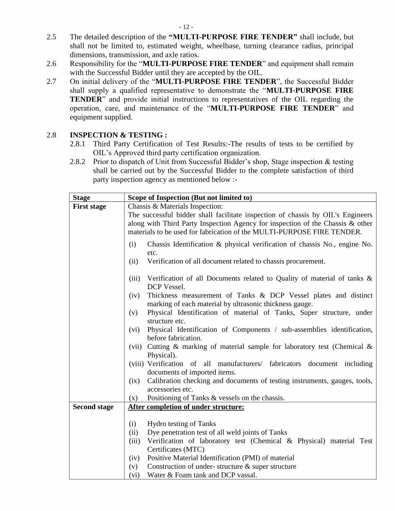
2.8 INSPECTION & TESTING :
2.8.1 Third Party Certification of Test Results:-The results of tests to be certified by
OIL’s Approved third party certification organization.
2.8.2 Prior to dispatch of Unit from Successful Bidder’s shop, Stage inspection & testing
shall be carried out by the Successful Bidder to the complete satisfaction of third
party inspection agency as mentioned below :-
Stage Scope of Inspection (But not limited to)
First stage Chassis & Materials Inspection:
The successful bidder shall facilitate inspection of chassis by OIL's Engineers
along with Third Party Inspection Agency for inspection of the Chassis & other
materials to be used for fabrication of the MULTI-PURPOSE FIRE TENDER.
(i) Chassis Identification & physical verification of chassis No., engine No.
etc.
(ii) Verification of all document related to chassis procurement.
(iii) Verification of all Documents related to Quality of material of tanks &
DCP Vessel.
(iv) Thickness measurement of Tanks & DCP Vessel plates and distinct
marking of each material by ultrasonic thickness gauge.
(v) Physical Identification of material of Tanks, Super structure, under
structure etc.
(vi) Physical Identification of Components / sub-assemblies identification,
before fabrication.
(vii) Cutting & marking of material sample for laboratory test (Chemical &
Physical).
(viii) Verification of all manufacturers/ fabricators document including
documents of imported items.
(ix) Calibration checking and documents of testing instruments, gauges, tools,
accessories etc.
(x) Positioning of Tanks & vessels on the chassis.
Second stage After completion of under structure:
(i) Hydro testing of Tanks
(ii) Dye penetration test of all weld joints of Tanks
(iii) Verification of laboratory test (Chemical & Physical) material Test
Certificates (MTC)
(iv) Positive Material Identification (PMI) of material
(v) Construction of under- structure & super structure
(vi) Water & Foam tank and DCP vassal.
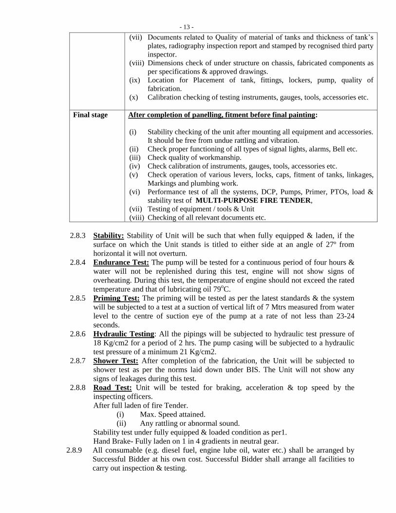
- 13 -
(vii) Documents related to Quality of material of tanks and thickness of tank’s
plates, radiography inspection report and stamped by recognised third party
inspector.
(viii) Dimensions check of under structure on chassis, fabricated components as
per specifications & approved drawings.
(ix) Location for Placement of tank, fittings, lockers, pump, quality of
fabrication.
(x) Calibration checking of testing instruments, gauges, tools, accessories etc.
Final stage After completion of panelling, fitment before final painting:
(i) Stability checking of the unit after mounting all equipment and accessories.
It should be free from undue rattling and vibration.
(ii) Check proper functioning of all types of signal lights, alarms, Bell etc.
(iii) Check quality of workmanship.
(iv) Check calibration of instruments, gauges, tools, accessories etc.
(v) Check operation of various levers, locks, caps, fitment of tanks, linkages,
Markings and plumbing work.
(vi) Performance test of all the systems, DCP, Pumps, Primer, PTOs, load &
stability test of MULTI-PURPOSE FIRE TENDER,
(vii) Testing of equipment / tools & Unit
(viii) Checking of all relevant documents etc.
2.8.3 Stability: Stability of Unit will be such that when fully equipped & laden, if the
surface on which the Unit stands is titled to either side at an angle of 27º from
horizontal it will not overturn.
2.8.4 Endurance Test: The pump will be tested for a continuous period of four hours &
water will not be replenished during this test, engine will not show signs of
overheating. During this test, the temperature of engine should not exceed the rated
temperature and that of lubricating oil 79oC.
2.8.5 Priming Test: The priming will be tested as per the latest standards & the system
will be subjected to a test at a suction of vertical lift of 7 Mtrs measured from water
level to the centre of suction eye of the pump at a rate of not less than 23-24
seconds.
2.8.6 Hydraulic Testing: All the pipings will be subjected to hydraulic test pressure of
18 Kg/cm2 for a period of 2 hrs. The pump casing will be subjected to a hydraulic
test pressure of a minimum 21 Kg/cm2.
2.8.7 Shower Test: After completion of the fabrication, the Unit will be subjected to
shower test as per the norms laid down under BIS. The Unit will not show any
signs of leakages during this test.
2.8.8 Road Test: Unit will be tested for braking, acceleration & top speed by the
inspecting officers.
After full laden of fire Tender.
(i) Max. Speed attained.
(ii) Any rattling or abnormal sound.
Stability test under fully equipped & loaded condition as per1.
Hand Brake- Fully laden on 1 in 4 gradients in neutral gear.
2.8.9 All consumable (e.g. diesel fuel, engine lube oil, water etc.) shall be arranged by
Successful Bidder at his own cost. Successful Bidder shall arrange all facilities to
carry out inspection & testing.
- 14 -
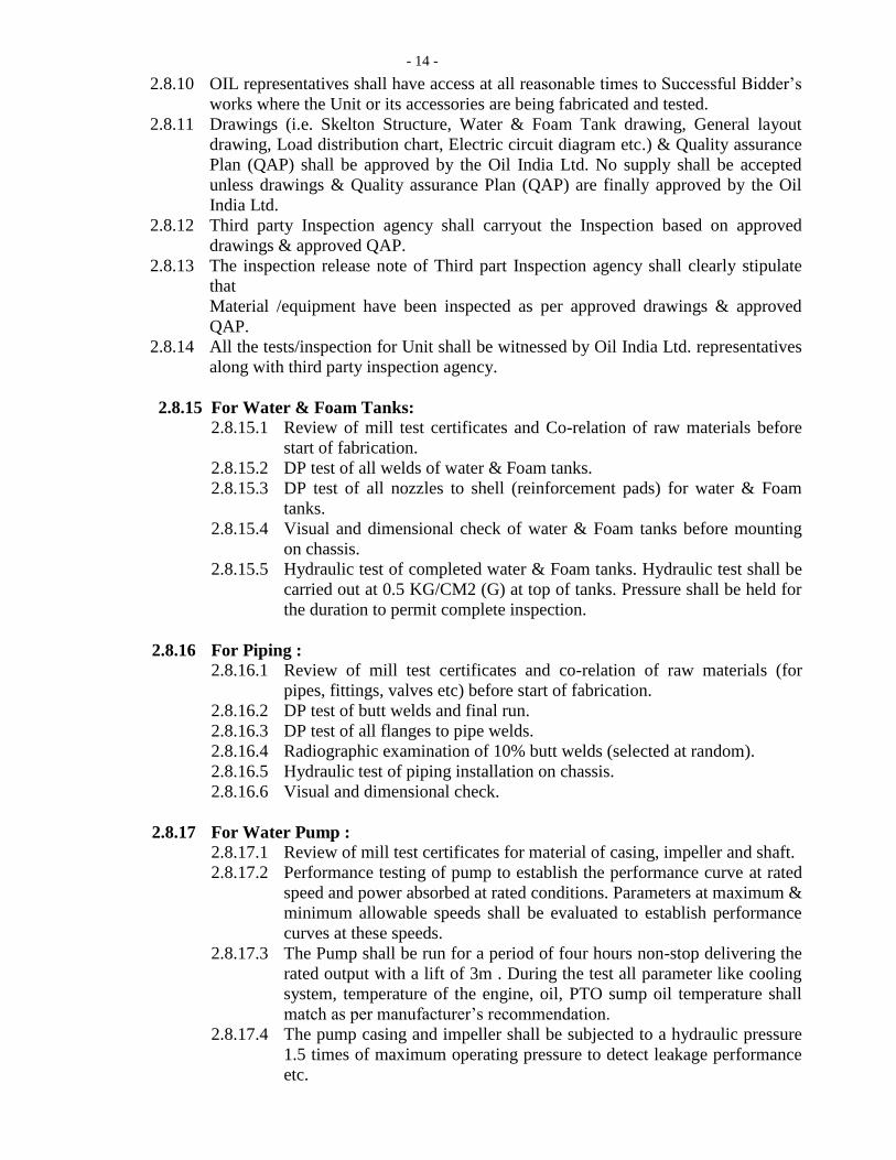
2.8.10 OIL representatives shall have access at all reasonable times to Successful Bidder’s
works where the Unit or its accessories are being fabricated and tested.
2.8.11 Drawings (i.e. Skelton Structure, Water & Foam Tank drawing, General layout
drawing, Load distribution chart, Electric circuit diagram etc.) & Quality assurance
Plan (QAP) shall be approved by the Oil India Ltd. No supply shall be accepted
unless drawings & Quality assurance Plan (QAP) are finally approved by the Oil
India Ltd.
2.8.12 Third party Inspection agency shall carryout the Inspection based on approved
drawings & approved QAP.
2.8.13 The inspection release note of Third part Inspection agency shall clearly stipulate
that
Material /equipment have been inspected as per approved drawings & approved
QAP.
2.8.14 All the tests/inspection for Unit shall be witnessed by Oil India Ltd. representatives
along with third party inspection agency.
2.8.15 For Water & Foam Tanks:
2.8.15.1 Review of mill test certificates and Co-relation of raw materials before
start of fabrication.
2.8.15.2 DP test of all welds of water & Foam tanks.
2.8.15.3 DP test of all nozzles to shell (reinforcement pads) for water & Foam
tanks.
2.8.15.4 Visual and dimensional check of water & Foam tanks before mounting
on chassis.
2.8.15.5 Hydraulic test of completed water & Foam tanks. Hydraulic test shall be
carried out at 0.5 KG/CM2 (G) at top of tanks. Pressure shall be held for
the duration to permit complete inspection.
2.8.16 For Piping :
2.8.16.1 Review of mill test certificates and co-relation of raw materials (for
pipes, fittings, valves etc) before start of fabrication.
2.8.16.2 DP test of butt welds and final run.
2.8.16.3 DP test of all flanges to pipe welds.
2.8.16.4 Radiographic examination of 10% butt welds (selected at random).
2.8.16.5 Hydraulic test of piping installation on chassis.
2.8.16.6 Visual and dimensional check.
2.8.17 For Water Pump :
2.8.17.1 Review of mill test certificates for material of casing, impeller and shaft.
2.8.17.2 Performance testing of pump to establish the performance curve at rated
speed and power absorbed at rated conditions. Parameters at maximum &
minimum allowable speeds shall be evaluated to establish performance
curves at these speeds.
2.8.17.3 The Pump shall be run for a period of four hours non-stop delivering the
rated output with a lift of 3m . During the test all parameter like cooling
system, temperature of the engine, oil, PTO sump oil temperature shall
match as per manufacturer’s recommendation.
2.8.17.4 The pump casing and impeller shall be subjected to a hydraulic pressure
1.5 times of maximum operating pressure to detect leakage performance
etc.
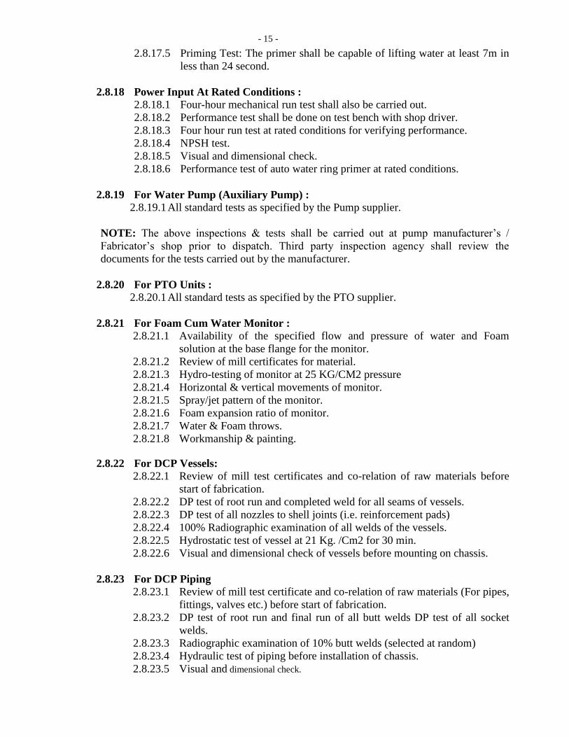
- 15 -
2.8.17.5 Priming Test: The primer shall be capable of lifting water at least 7m in
less than 24 second.
2.8.18 Power Input At Rated Conditions :
2.8.18.1 Four-hour mechanical run test shall also be carried out.
2.8.18.2 Performance test shall be done on test bench with shop driver.
2.8.18.3 Four hour run test at rated conditions for verifying performance.
2.8.18.4 NPSH test.
2.8.18.5 Visual and dimensional check.
2.8.18.6 Performance test of auto water ring primer at rated conditions.
2.8.19 For Water Pump (Auxiliary Pump) :
2.8.19.1 All standard tests as specified by the Pump supplier.
NOTE: The above inspections & tests shall be carried out at pump manufacturer’s /
Fabricator’s shop prior to dispatch. Third party inspection agency shall review the
documents for the tests carried out by the manufacturer.
2.8.20 For PTO Units :
2.8.20.1 All standard tests as specified by the PTO supplier.
2.8.21 For Foam Cum Water Monitor :
2.8.21.1 Availability of the specified flow and pressure of water and Foam
solution at the base flange for the monitor.
2.8.21.2 Review of mill certificates for material.
2.8.21.3 Hydro-testing of monitor at 25 KG/CM2 pressure
2.8.21.4 Horizontal & vertical movements of monitor.
2.8.21.5 Spray/jet pattern of the monitor.
2.8.21.6 Foam expansion ratio of monitor.
2.8.21.7 Water & Foam throws.
2.8.21.8 Workmanship & painting.
2.8.22 For DCP Vessels:
2.8.22.1 Review of mill test certificates and co-relation of raw materials before
start of fabrication.
2.8.22.2 DP test of root run and completed weld for all seams of vessels.
2.8.22.3 DP test of all nozzles to shell joints (i.e. reinforcement pads)
2.8.22.4 100% Radiographic examination of all welds of the vessels.
2.8.22.5 Hydrostatic test of vessel at 21 Kg. /Cm2 for 30 min.
2.8.22.6 Visual and dimensional check of vessels before mounting on chassis.
2.8.23 For DCP Piping
2.8.23.1 Review of mill test certificate and co-relation of raw materials (For pipes,
fittings, valves etc.) before start of fabrication.
2.8.23.2 DP test of root run and final run of all butt welds DP test of all socket
welds.
2.8.23.3 Radiographic examination of 10% butt welds (selected at random)
2.8.23.4 Hydraulic test of piping before installation of chassis.
2.8.23.5 Visual and dimensional check.
- 16 -
2.8.24 For “Multi-Purpose Fire Tender” (During Fabrication & Assembly) :
2.8.24.1 Review of mill test certificates and co-relation of raw materials used for
structure & body fabrication before start of fabrication.
2.8.24.2 Inspection of framework for soundness of welding and fitment of chassis
and dimensional check.
2.8.24.3 Inspection for proper installation of pumps, tanks, piping with supports and
their dimensional checks.
2.8.24.4 Inspection for proper installation of DCP vessels, piping with supporting
etc. and dimensional check.
2.8.24.5 Visual inspection of raw materials for framework, cladding, flooring etc.
2.8.25 For Completed Unit :
2.8.25.1 All consumables (Foam, DCP, Nitrogen gas in cylinders, fuel, engine lube
oil, Water etc.) required during inspection & testing shall be arranged by
Successful Bidder at his own cost. Successful Bidder shall arrange all
facilities to carry out inspection & testing.
2.8.25.2 Determination of actual payload on the chassis so as to confirm payload
given by Successful Bidder in the bid. For determining actual laden weight,
all tanks shall be full, all removable accessories will be on Unit with a crew
of six.
2.8.25.3 For determining actual payload all Tanks & vessel shall be charged to rated
capacity, charged nitrogen cylinders on board, all removable accessories
will be on Unit with crew of six.
2.8.25.4 Static stability of the fully laden Unit shall be checked to ensure that no
overturning occurs till Unit attains tilting of 35 ± 1 degrees from horizontal.
2.8.25.5 Road test of the fully laden Unit shall be carried out to ensure the maximum
speed, acceleration, turning radius, breaking ability as specified by chassis
manufacture.
2.8.25.6 Dimensional check of completed Unit. The overall height shall be measured
both when Unit is laden with full payload and un-laden.
2.8.25.7 Test to confirm functional capability of the “MULTI-PURPOSE FIRE
TENDER” shall be carried out:
2.8.25.7.1 Running of water pump at rated conditions while discharging water
through various outlets individually and in combination.
2.8.25.7.2 The pump shall be run for minimum 4 hours continuously at rated
conditions.
2.8.25.7.3 Functional testing of each water outlet (hose point / hose reel)
individually and in combination.
2.8.25.7.4 Performance tests of Foam-cum water monitor.
2.8.25.7.5 Performance tests of Foam-cum-water monitor with water through
hydrant inlets.
2.8.25.7.6 Functional testing of each hose outlet individually and in
combination.
2.8.25.7.7 Vibrations at rotary parts
2.9 Personnel Protection :
2.9.1 Electrical insulation or isolation shall be provided where necessary in order to
prevent electrical shock from onboard electrical systems.
2.9.2 Workmanship shall ensure an operating environment free of accessible sharp
projections and edges.
- 17 -
2.9.3 Safety-related (caution, warning, danger) signs shall meet the requirements of job.
2.10 Controls and Instructions :
2.10.1 Illumination shall be provided for controls, switches, instruction plates, gauges, and
instruments necessary for the operation of the “MULTI-PURPOSE FIRE
TENDER” and the equipment provided on it.
2.10.2 All required signs, plates, and labels shall be permanent in nature and securely
attached
2.10.3 No gauge or visual display shall be more than 84 in. (2.1 m) above the level where
the operator stands to read the instrument.
2.11 Unit Stability :
2.11.1 When the “MULTI-PURPOSE FIRE TENDER” is loaded to its maximum in-
service weight, the height of the Unit's center of gravity shall not exceed the chassis
manufacturer's maximum limit.
2.12 Weight Distribution :
2.12.1 When the “MULTI-PURPOSE FIRE TENDER” is loaded to its maximum in-
service weight, the front-to-rear weight distribution of the “MULTI-PURPOSE
FIRE TENDER” as defined shall be within the limits set by the chassis
manufacturer.
2.12.2 The axle loads shall not be more than the axle loads specified by the chassis
manufacturer under full load and all other loading conditions.
2.13 Load Distribution :
2.13.1 Using the information supplied by the OIL, the “MULTI-PURPOSE FIRE
TENDER” manufacturer shall calculate the load distribution for the “MULTI-
PURPOSE FIRE TENDER”.
2.13.2 The manufacturer shall engineer the “MULTI-PURPOSE FIRE TENDER” to
comply with the gross axle weight ratings (GAWR), the overall gross Unit weight
rating (GVWR), and the chassis manufacturer's load balance guidelines.
2.13.3 The total laden weight of the unit should not exceed the permissible GVW of
Unit.
2.14 MULTI-PURPOSE FIRE TENDER Performance :
2.14.1 The MULTI-PURPOSE FIRE TENDER shall meet all the requirements while
stationary on a grade of 6 percent in any direction.
2.15 Serviceability :
2.15.1 Where special tools are required for routine service on any component of the
MULTI-PURPOSE FIRE TENDER, such tools shall be provided with the MULTI-
PURPOSE FIRE TENDER.
2.16 Road Tests :
2.16.1 Road tests shall be conducted in accordance with this section to verify that the
completed MULTI-PURPOSE FIRE TENDER is capable of compliance
roadability.
2.17 INFORMATION / DOCUMENTS REQUIRED FROM SUCCESSFUL BIDDER :
- 18 -
2.17.1 Any documentation provided with the MULTI-PURPOSE FIRE TENDER shall be
permitted to be in printed format, electronic format, audiovisual format or a
combination thereof.
2.17.2 All drawings & literature shall be kept in Proper folders.
2.17.3 All literature shall be on A-4 size paper and shall be properly laminated.
2.17.4 Each drawing shall be kept in separate pockets in folder. Contents in each pocket
shall be labelled properly.
2.17.4.1 AFTER PLACEMENT OF ORDER :
The following documents are required to be submitted in 2 sets and to be
approved prior to start of fabrication:
2.17.4.1.1 Flow diagram showing all piping tanks, pumps, valves etc.
2.17.4.1.2 GA & cross sectional drawings, characteristic curves and other
details for water pump.
2.17.4.1.3 Internal Drawings for PTO Unit and other technical details.
2.17.4.1.4 Drawings for PTO system to drive pumps from engine.
2.17.4.1.5 Detailed Drawing for Foam-cum water monitor.
2.17.4.1.6 Fabrication drawings & data for water tanks.
2.17.4.1.7 Line diagram for electrical circuits.
2.17.4.1.8 Drawings showing layout of all equipment, lockers, cabin etc.
2.17.4.1.9 QAP incorporating the stipulated inspection and testing
requirements.
2.17.4.2 AFTER COMPLETION OF ORDER (4 SETS) :
The manufacturer's record of MULTI-PURPOSE FIRE TENDER
construction details, including the following Information:
2.17.4.2.1 M/s Oil India Ltd. name and address (Oil India Ltd., Duliajan,
Dibrugarh , Assam.)
2.17.4.2.2 MULTI-PURPOSE FIRE TENDER manufacturer, model, and
serial number
2.17.4.2.3 Chassis make, model, and serial number.
2.17.4.2.4 Front tire size and total rated capacity in pounds (kilograms)
2.17.4.2.5 Rear tire size and total rated capacity in pounds (kilograms)
2.17.4.2.6 Chassis weight distribution in pounds (kilograms) with water &
manufacturer mounted equipment (front and rear)
2.17.4.2.7 Engine make, model, serial number, rated horsepower and related
speed, and governed speed
2.17.4.2.8 Fuel tank capacity
2.17.4.2.9 Battery make, model, and capacity in cold cranking amps (CCA)
2.17.4.2.10 Chassis transmission make, model, and serial number
2.17.4.2.11 Chassis transmission PTO(s) make, model, and gear ratio
2.17.4.2.12 Pump make, model, rated capacity in liters per minute and serial
number
2.17.4.2.13 Water & Foam tanks certified capacity in liters.
2.17.4.2.14 Paint manufacturer and paint number(s)
2.17.4.2.15 As built drawings of MULTI-PURPOSE FIRE TENDER
2.17.4.2.16 As built drawings for tanks.
2.17.4.2.17 Flow diagram.
2.17.4.2.18 GA & cross sectional drawings, characteristic curves and other
details for water pump.
- 19 -
2.17.4.2.19 As built Drawings for Installation of PTO Units.
2.17.4.2.20 As built Drawing for Foam-cum water monitor.
2.17.4.2.21 As built Line diagram for electrical circuits.
2.17.4.2.22 All inspection and testing records for tank, pump, PTO’s, piping,
valves, monitor etc.
2.17.4.2.23 Operating and instruction manual for the MULTI-PURPOSE FIRE
TENDER. This should also contain adequate information for all
bought out items also.
2.17.4.2.24 Fire pump manufacturer's certification of suction capability
2.17.4.2.25 Fire pump, the pump manufacturer's certification of the hydrostatic
test
2.17.4.2.26 Weight documents showing actual loading of “MULTI-PURPOSE
FIRE TENDER” (with the full extinguishing media but without
personnel, equipment, and hose).
2.17.4.2.27 Operations and Service Documentation :
2.17.4.2.27.1 The Successful Bidder shall supply operation and service
documentation covering the completed MULTI-PURPOSE
FIRE TENDER as delivered and accepted.
2.17.4.2.27.2 The documentation shall address at least the inspection,
service, and operations of the “MULTI-PURPOSE FIRE
TENDER” and all major components thereof.
3.0 MULTI-PURPOSE FIRE TENDER EQUIPMENT:
3.1 Equipment Storage :
3.1.1 A minimum of 20 ft3
(0.6 m3) of enclosed weather-resistant compartmentation
meeting the requirements for the storage of equipment.
3.2 Hose Storage :
3.2.1 A minimum hose storage area of 6 ft3 (0.2 m3) for 2½ in. (65 mm) or larger fire
hose that meets the requirements.
3.3 Minor Equipment :
3.3.1 Brackets or compartments shall be furnished so as to organize and mount the
specified equipment.
3.3.2 Following equipments shall be supplied:
3.3.2.1 One first aid kit
3.3.2.2 One Nos. HDPE Long Spine Boards Stretcher.
3.3.2.3 Two combination spanner wrenches
3.3.2.4 Two hydrant wrench
3.3.2.5 Double female adapter, sized to fit 2½ in. (65 mm) conforming to IS-
901/1993- 5 Nos. (In locker)
3.3.2.6 Double male adapter, sized to fit 2½ in. (65 mm) conforming to IS-
901/1993- 5 Nos. (In locker)
3.3.2.7 Four Nos. wheel chocks with chain link, mounted in readily accessible
locations, each designed to hold the MULTI-PURPOSE FIRE TENDER.
3.3.2.8 A 24 volts DC operated GRAND make blinker light bar (minimum three
blinkers on each side) with PA system and siren shall be provided on top of
the Unit with firm support and assembly shall be covered with SS grill.
- 20 -
Assembly shall be operable from cabin- 1 No. (fitted on roof, operable
from cabin)
3.3.2.9 Fog lamps powered by the battery of the Unit- 2 Nos. (Fitted on front of
MULTI-PURPOSE FIRE TENDER. Switch in cabin).
3.3.2.10 Reversing lights-2 Nos. (At rear of chassis)
3.3.2.11 Strong Reversing siren connected with reverse gear of the Unit-1 set
(Mounted on roof)
3.3.2.12 Search light with 100M length of cable with tripod etc. completes powered
from main batteries - 1 set (mounted on roof)
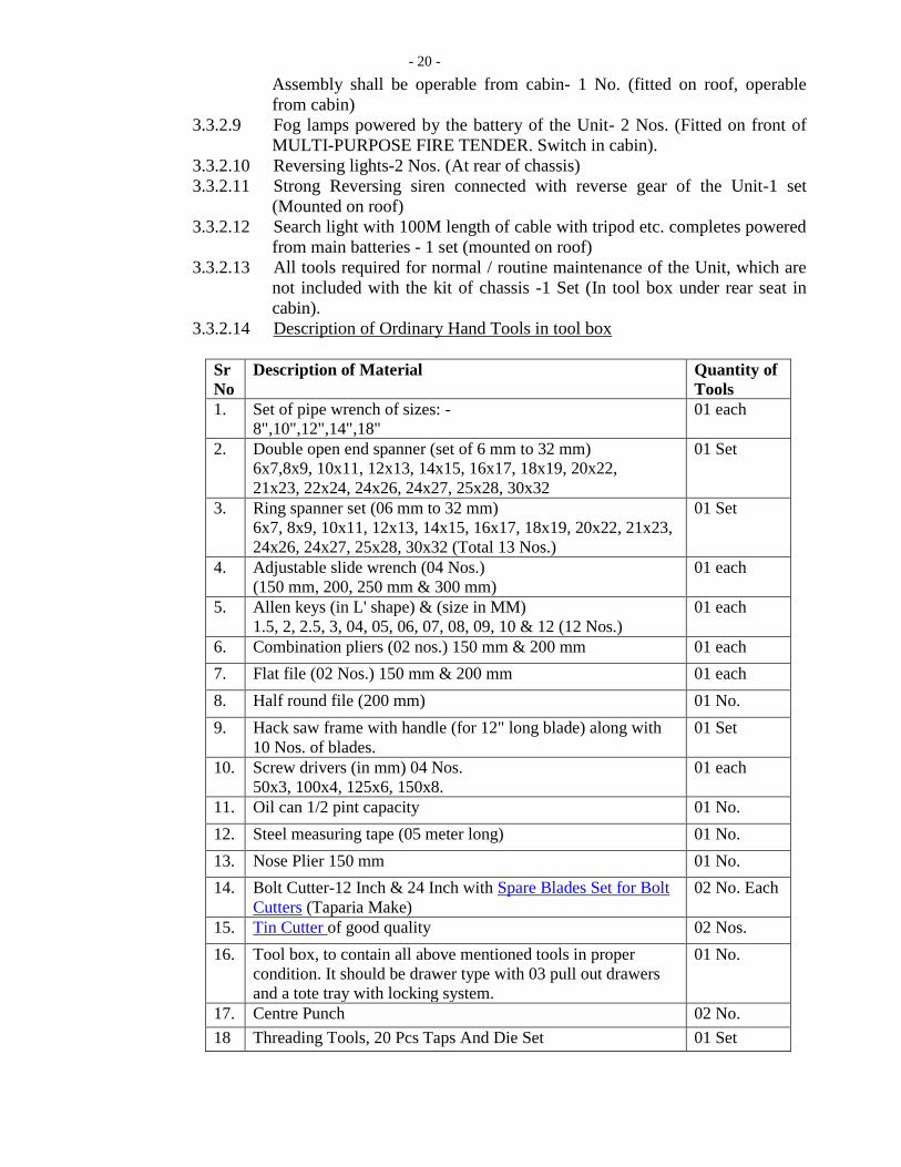
3.3.2.13 All tools required for normal / routine maintenance of the Unit, which are
not included with the kit of chassis -1 Set (In tool box under rear seat in
cabin).
3.3.2.14 Description of Ordinary Hand Tools in tool box
Sr
No
Description of Material
Quantity of
Tools
1. Set of pipe wrench of sizes: -
8",10",12",14",18"
01 each
2.
Double open end spanner (set of 6 mm to 32 mm)
6x7,8x9, 10x11, 12x13, 14x15, 16x17, 18x19, 20x22,
21x23, 22x24, 24x26, 24x27, 25x28, 30x32
01 Set
3.
Ring spanner set (06 mm to 32 mm)
6x7, 8x9, 10x11, 12x13, 14x15, 16x17, 18x19, 20x22, 21x23,
24x26, 24x27, 25x28, 30x32 (Total 13 Nos.)
01 Set
4.
Adjustable slide wrench (04 Nos.)
(150 mm, 200, 250 mm & 300 mm) 01 each
5.
Allen keys (in L' shape) & (size in MM)
1.5, 2, 2.5, 3, 04, 05, 06, 07, 08, 09, 10 & 12 (12 Nos.)
01 each
6. Combination pliers (02 nos.) 150 mm & 200 mm 01 each
7. Flat file (02 Nos.) 150 mm & 200 mm 01 each
8. Half round file (200 mm) 01 No.
9.
Hack saw frame with handle (for 12" long blade) along with
10 Nos. of blades. 01 Set
10.
Screw drivers (in mm) 04 Nos.
50x3, 100x4, 125x6, 150x8.
01 each
11. Oil can 1/2 pint capacity 01 No.
12. Steel measuring tape (05 meter long) 01 No.
13. Nose Plier 150 mm 01 No.
14. Bolt Cutter-12 Inch & 24 Inch with Spare Blades Set for Bolt
Cutters (Taparia Make)
02 No. Each
15. Tin Cutter of good quality 02 Nos.
16.
Tool box, to contain all above mentioned tools in proper
condition. It should be drawer type with 03 pull out drawers
and a tote tray with locking system.
01 No.
17. Centre Punch 02 No.
18 Threading Tools, 20 Pcs Taps And Die Set 01 Set

- 21 -
3.3.2.15 PESO/CCE approved removable spark arrestor (If chassis manufacturer
not provided) fitted to the exhaust of the engine - 1 No.
3.3.2.16 Stainless Steel dividing breeching each having two 63MM female
instantaneous type outlets, conforming to IS-905/1980- 1 Nos. (In Locker)
3.3.2.17 Stainless Steel collecting breeching each having two 63MM male
instantaneous type outlets, conforming to IS-905/1980- 1 Nos. (In Locker)
3.3.2.18 Stainless Steel 3 way suction collecting head (With one 140MM outlet
with round female threads and two female instantaneous type inlets),
conforming to IS-904/1983-1 Nos. (In Locker).
3.3.2.19 Lightweight PVC rubber suction hose fitted with round thread male-female
gun metal couplings. Length – 4.5 meter, Diameter: as per pump suction -
4 Nos. (In compartment on top deck, Compartment shall be open able from
top with latching system)
3.3.2.20 Suction strainer with foot valve size to suit suction hose as per IS: 907-
1984 - 1 Nos. (In locker)
3.3.2.21 Stainless steel foot strainer-1 Nos. (In locker)
3.3.2.22 Suction Wrench to tighten suction hose as per IS:4643- 04 Nos. (In locker)
3.3.2.23 Hose clamps as per IS:5612 (Part-1-1977) - 2 Nos. (In locker)
3.3.2.24 TFT make (G Force Selectable flow 110 to 570 LPM @ 7 bar) hand
controlled non-aspirating aqua fog / Foam type nozzles having spray/jet
pattern with variable flow & low pressure features (suitable for both Foam
& water)– 2 Nos. (in locker)
3.3.2.25 Low pressure diffuser branch, conforming to IS-903/1993- 1 Nos. (In
locker)
3.3.2.26 Fireman’s axe with belt and pouches conforming to IS: 3650-1981- 02
Nos. (In locker)
3.3.2.27 Crow bar (IS: 704-1984)- 1 No. (In locker)
3.3.2.28 Sledge hammer - 1 No. (In locker)
3.3.2.29 Female Adopter (140 mm X 100 mm) - 02 Nos.
3.3.2.30 Spade – 02 No.
3.3.2.31 Ceiling Fire hook as per IS:927:1981-2007 or latest - 1 No.
3.3.2.32 One 6 lb (2.7 kg) flathead or pick head axe mounted in a bracket fastened
to the Tender
3.3.2.33 Door Breaker-01 No.
3.3.2.34 Carpenter saw-01 No.
3.3.2.35 Inline inductor 225 LPm-01 No.
3.3.2.36 Inline inductor 450 LPM- 01 No.
3.3.2.37 ISI marked 63MM SS male instantaneous couplings (threaded) with caps -
2 Sets.
3.3.2.38 ISI marked 63MM SS female instantaneous couplings (threaded) with caps
- 2 Sets.
3.3.2.39 Hydrant key for 4” Gate valve : 10 nos.
3.3.2.40 Hydrant Key for 2 ½’’ hydrant valve: 10 Nos.
3.3.2.41 Suction adopter (Stainless Steel) 4 inch round threaded by 63 mm
instantaneous male coupling -02 Nos.
3.3.2.42 Portable Pressure gauge for checking of Tyre Air Pressure.
3.3.2.43 Hydraulic Jack (Floor Type) ) – 15 to 20 Ton capacity.
3.3.2.44 Curtain Nozzle with 63 MM Male Instantaneous, Stainless Steel with
portable with Carrying Handle (Make: Newage/ Shah Bhogilal/ TFT/
Akron) - 04 Nos.
- 22 -
3.3.2.45 Zero Torque Nozzle: Multipurpose pistol grip lightweight aluminium alloy
construction nozzle with Zero-Torque technology with various flow
settings & spinning teeth. Flow: 115-360-475-550-750 LPM along with
foam barrel attachment (Make: Newage/ Shah Bhogilal/ TFT/ Akron) -04
Nos.
3.3.2.46 Fast Action Nozzle Arrangement for Detent flows To shut off pressure
assisted flush without shutting down Slide type valve for turbulence free
flow moulded rubber B teeth for full fill Power for gasket grabber inlet
screen Pistol type grip for holding Flow straightness for quality jet stream
Suitable for flow of 450 LPM at 7kg/cm² with inlet of 63mm size Weight
1.6 kg approximately along with foam barrel attachment (Make: Newage/
Shah Bhogilal/ TFT/ Akron) - 04 No.
3.3.2.47 Dual Pressure Nozzle Fast Action Nozzle Standard & Emergency Mode
with 185 -224 GPM @7 Kg/cm2 (Make: Newage/ Shah Bhogilal/ TFT/
Akron) - 04 Nos.
4.0 CHASSIS AND UNIT COMPONENTS : 4.1 Welding and drilling on frame work of chassis are not allowed.
4.2 An engine hour-meter shall be provided.
4.3 An angle of approach and an angle of departure of at least 8 degrees shall be maintained at
the front and the rear of the Unit when it is loaded.
4.4 POWER TAKE OFF UNITS :
4.4.1 Power take-off (PTO) unit for the main water pump shall be independent type. (Vas
Make)
4.4.2 The PTO operation shall be through Pneumatic as well as mechanical cable
linkage.
4.4.3 The power takes off unit for main water pump shall be of suitable model. The PTO
shall be able to meet performance requirement of pump.
4.4.4 Successful Bidder shall submit a sketch showing the arrangement of PTO Unit for
taking power from main engine on chassis to main water pump.
4.4.5 The drive assembly components (shaft, coupling etc) shall be dynamically balanced
and the vibration at any of the rotary parts shall be minimum and in no case shall be
more than 10mm/sec. Necessary modifications, to the standard drive system as
available on the chassis, shall have to be done by the Successful Bidder so as to
adopt the PTO Units in the system.
4.5 FOR OTHER WORK ON CHASSIS :
4.5.1 No part of the bodywork shall reduce ground clearance of Unit to less than 36cm.
& not increase the overall width to more than 2.60M. The highest part of the Unit
with the monitor mounted on it shall not exceed 3.60M from the ground level. The
construction of super-structure shall not reduce the angles of approach below 30
degree.
4.5.2 3M/Hi-tech/ Zenith make anti-vibration rubber mats shall be provided while
mounting the tanks etc. on the chassis.
4.5.3 Reflective stripe(s) shall be affixed to the perimeter of the unit as per MVA.
4.5.4 Arrangement shall be made on Dashboard opposite to the fire officers’ seat to fix a
Motorola mobile wireless set of 25W capacity. Power supply shall be provided
from Unit battery. M/s Oil India Ltd. shall fit wireless set later.
- 23 -
4.6 Optical Warning Devices :
4.6.1 MULTI-PURPOSE FIRE TENDER shall have a system of optical warning devices
4.6.2 The optical warning system shall consist of an upper and a lower warning level.
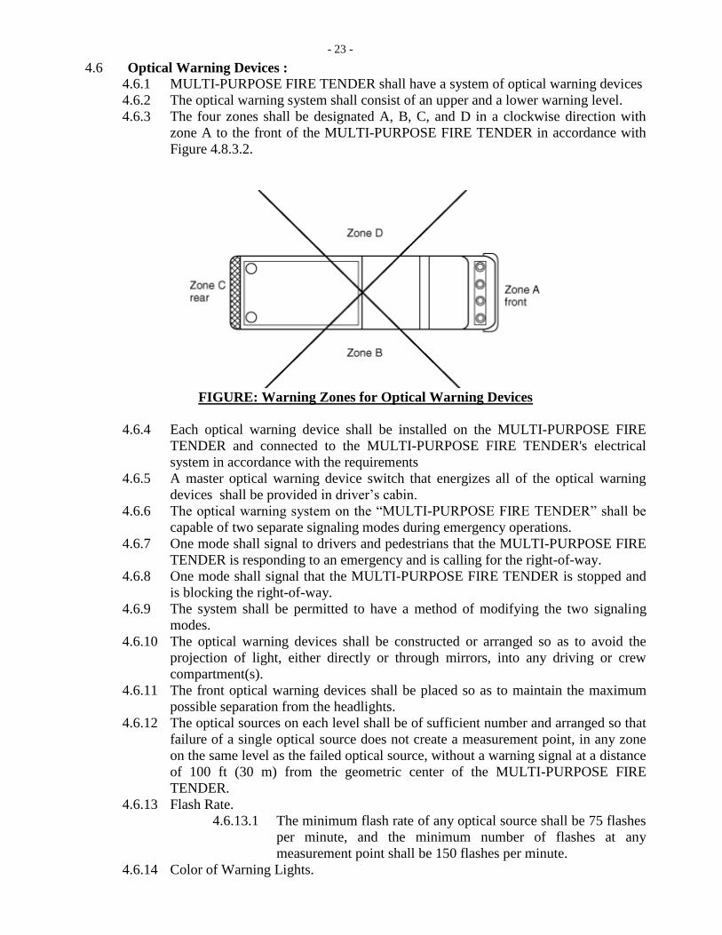
4.6.3 The four zones shall be designated A, B, C, and D in a clockwise direction with
zone A to the front of the MULTI-PURPOSE FIRE TENDER in accordance with
Figure 4.8.3.2.
FIGURE: Warning Zones for Optical Warning Devices
4.6.4 Each optical warning device shall be installed on the MULTI-PURPOSE FIRE
TENDER and connected to the MULTI-PURPOSE FIRE TENDER's electrical
system in accordance with the requirements
4.6.5 A master optical warning device switch that energizes all of the optical warning
devices shall be provided in driver’s cabin.
4.6.6 The optical warning system on the “MULTI-PURPOSE FIRE TENDER” shall be
capable of two separate signaling modes during emergency operations.
4.6.7 One mode shall signal to drivers and pedestrians that the MULTI-PURPOSE FIRE
TENDER is responding to an emergency and is calling for the right-of-way.
4.6.8 One mode shall signal that the MULTI-PURPOSE FIRE TENDER is stopped and
is blocking the right-of-way.
4.6.9 The system shall be permitted to have a method of modifying the two signaling
modes.
4.6.10 The optical warning devices shall be constructed or arranged so as to avoid the
projection of light, either directly or through mirrors, into any driving or crew
compartment(s).
4.6.11 The front optical warning devices shall be placed so as to maintain the maximum
possible separation from the headlights.
4.6.12 The optical sources on each level shall be of sufficient number and arranged so that
failure of a single optical source does not create a measurement point, in any zone
on the same level as the failed optical source, without a warning signal at a distance
of 100 ft (30 m) from the geometric center of the MULTI-PURPOSE FIRE
TENDER.
4.6.13 Flash Rate.
4.6.13.1 The minimum flash rate of any optical source shall be 75 flashes
per minute, and the minimum number of flashes at any
measurement point shall be 150 flashes per minute.
4.6.14 Color of Warning Lights.
- 24 -
4.6.14.1 Permissible colors or combinations of colors in each zone,
within the constraints imposed by applicable laws and
regulations, shall be as shown in Table.
Table Zone Colors
Color Calling for Right-of-Way Blocking Right-of-Way
Red Any zone Any zone
Blue Any zone Any zone
Yellow Any zone except
A Any zone
White Any zone except
C Not permitted
4.6.15 Audible Warning Devices :
4.6.15.1 Audible warning equipment in the form of at least one
automotive traffic horn and one electric or electronic siren shall
be provided.
4.6.15.2 A means shall be provided to allow the activation of the siren
within convenient reach of the driver.
4.7 Work Lighting :
4.7.1 Ground Lighting :
4.7.1.1 The work area immediately behind the Unit shall be illuminated
4.7.1.2 The “MULTI-PURPOSE FIRE TENDER” shall be equipped
with lighting that is capable of providing illumination on ground
areas within 30 in. (800 mm) of the edge of the MULTI-
PURPOSE FIRE TENDER in areas designed for personnel to
climb onto the MULTI-PURPOSE FIRE TENDER or descend
from the MULTI-PURPOSE FIRE TENDER to the ground
level.
4.7.1.3 All other ground area lighting shall be switchable.
4.7.1.4 Surface Lighting: The MULTI-PURPOSE FIRE TENDER shall
have sufficient lighting on all work surfaces, steps, and
walkways.
4.7.1.5 Interior Lighting: The MULTI-PURPOSE FIRE TENDER shall
have sufficient lighting to provide in the driving and crew
compartments.
4.7.1.6 Compartment Lighting Each engine compartment and pump
compartment shall have a light.
4.7.1.7 Each enclosed tool and equipment compartment greater than 4
ft3 (0.1 m3) in volume and having an opening greater than 144
in.2 (0.9 m2) shall have an average minimum level of lighting.
4.7.1.8 Switches for all work lighting shall be readily accessible.
4.7.1.9 The lights shall be arranged or protected to minimize accidental
breakage.
4.7.2 Backup Alarm (Reverse Horn) :

- 25 -
4.7.2.1 An electric or electronic backup alarm (Reverse Horn) with
light indication shall be provided that meets the Type D (87
dBA) requirements.
4.7.3 The MULTI-PURPOSE FIRE TENDER shall be equipped with all legally required
stop, tail, and directional lights.
4.7.4 Directional lights shall be visible from the front, sides, and rear of the MULTI-
PURPOSE FIRE TENDER.
4.7.5 Equipment shall not be mounted in a manner that obscures the stop, tail, or
directional lights.
5.0 DRIVING AND CREW AREAS:
5.1 General :
5.1.1 Each crew riding position shall be within a fully enclosed personnel area.
5.1.2 All interior crew and driving compartment door handles shall be designed and
installed to protect against accidental or inadvertent opening.
5.1.3 Means of Escape :
5.1.3.1 Any interior area to be occupied by personnel shall have a minimum of two
means of escape.
5.1.3.2 Each opening shall be large enough for a person to escape through the
opening.
5.1.4 Instrumentation and Controls :
5.1.4.1 All the standard instrumentation and controls shall be mounted in the
driving compartment and shall be identified and visible to the driver while
seated.
5.1.5 Controls and switches that are expected to be operated by the driver while the
MULTI-PURPOSE FIRE TENDER is in motion shall be within convenient reach
for the driver.
5.1.6 There shall be two doors in the cabin, sized generously with proper arrangement for
embarking and disembarking of crewmembers. The doors shall open outwards and
hung forward and shall have levers for unlatching from outside and inside. The
doors shall be provided with shatterproof safety glasses which can be raised /
lowered by winding type mechanism.
5.1.7 First aid box made of fiber glass/ aluminum suitable for 10 persons shall be
provided in the cabin. First aid box shall be suitably mounted in the cabin at easily
accessible location.
5.1.8 Non slip type steps & grab rails shall be provided in the cabin to assist the crew
members to get in & out. Front side of the cabin shall have glass paneling so that
the crew can have an all-round view.
5.1.9 The cabin structure shall be so designed so as to avoid any vibration / rattling /
deformation in the intended usage of the Unit. The entire floor of the cabin shall be
provided with 3M make vinyl matting of minimum 6MM thickness with anti-skid
features.
5.1.10 Battery shall be placed in totally enclosed box with spark proof gland for cable
entry with battery cut-Off switch. Installed battery shall have a charging faculty
from external source at its location itself.
5.2 Seating arrangement
- 26 -
5.2.1 Seating arrangement for 6 persons shall be provided in cabin.
5.2.2 For Driver & Officer In-charge each - “HO Bostrom, USA / Ziamatic/ USSC
Valor, USA make”
5.2.3 For Crew (04 Nos.) - “HO Bostrom, USA / Ziamatic/ USSC Valor, USA make”
6.0 BODY, COMPARTMENTS AND EQUIPMENT MOUNTING:
6.1 STRUCTURE / FRAME WORK :
6.1.1 The structure/frame work on chassis & crew cabin shall be of welded construction
and made from 30 mm X 30 mm X1.6 mm hollow square section of SS-316L and
distance between each horizontal and vertical square shall be maximum 400 mm.
Cross supporting members of the panelling shall be made of SS-316L channels of
75 mm X 5 mm thickness
6.1.2 The entire roof of the Unit including the crew cabin top, entire rear, crew cabin
floor, locker floor and sides shall be made from 2 MM of SS- 316L sheets suitably
treated for slippage and these shall be bolted to the frame for ease in removal of the
tank for repairs. The roof of the cabins should be rigid enough to take the weight of
two persons without deforming the roof sheeting.
6.1.3 Area around the monitors operation shall be provided with 16 SWG anodized
aluminum-checkered plate (in addition to the 2 mm Alluminum sheets) and shall be
bolted to the frame.
6.1.4 Proper access ladder with Grab rails and non-skid steps shall be provided to give
access to the roof for approaching to the manholes for tank and monitor etc.
6.1.5 Access handrails shall be provided at each entrance to a driving or crew
compartment and at each position where steps or ladders for climbing are located.
Access handrails shall be constructed of, or covered with, a slip-resistant, non-
corrosive material. Handrails shall be between 1 in. and 1-5/8 in. (25 mm and 41
mm) in diameter and have a minimum clearance between the handrails and any
surface of at least 2 in. (51 mm).
6.1.6 All handrails shall be designed and mounted to reduce the possibility of hand
slippage and to avoid snagging of hose, equipment, or clothing.
6.1.7 Single Roller type Sun Shade Screen Assembly and long arm outside fitting rear view mirrors shall
be fitted to cabin.
6.1.8 Proper draining arrangements shall be provided on the entire roof, crew cabin and
inside the lockers.
6.2 LOCKERS :
6.2.1 Size and number of locker shall be decided such that on either side 15 nos. 22.5 m
length fire hose can be easily accommodated in single layer and equipments may be
accommodated in maximum two layers. Sufficient numbers of lockers shall be
provided to accommodate all the equipment/accessories in an easily accessible
manner.
6.2.2 All lockers shall be provided with Roller type shutter doors. The shutters shall have
smooth operation. The aluminum shutters shall be dust & water proof of M/s.
MCD, France imported make only made of extruded aluminum & duly hard
anodized.
6.2.3 Roller shutters shall be of hollow rectangular shaped & made from aluminium
inter-changeable links connected by means of plastic profiles.
6.2.4 Sealing of roller shutter shall be watertight when closed.

- 27 -
6.2.5 Roller shutters shall be inward rolling type and shall be provided with guide rails
over entire length on both sides to make them torsion free.
6.2.6 When shutters are rolled, unobstructed access should be available to the equipment
& hoses.
6.2.7 Shutters should open in all positions of the Unit even in rough terrains.
6.2.8 Roller shutters shall have locking arrangement to prevent accidental opening during
movement of the Unit.
6.2.9 Spare lock – 10 Nos. shall be provided.
6.2.10 All the lockers shall be illuminated by MCD make LED lightning system.
6.2.11 All the lockers shall be fitted with internal lighting, which shall be capable of being
automatically switched, ‘ON’ and ‘OFF’ by the opening of shutters. A master
switch for isolating the locker lighting circuit shall also be fitted in the driver’s
cabin.
6.2.12 Lockers shall have arrangement for self draining of any water entering inside
6.2.13 Sufficient number of lockers shall be provided for storage of all accessories listed.
Lockers shall also be provided to accommodate 4 nos., 10 kg DCP extinguishers.
6.2.14 Lockers shall be accessible from ground level by a man of average height (1.67M).
All the Lockers shall be provided with 3M make, 4MM thick, vulcanized synthetic
rubber mat at bottom and up-to 12 inch on three sides.
6.2.15 The hose storage area(s) shall be reinforced at the corners.
6.2.16 The bottom shall be made of removable sections fabricated from noncorrosive
materials.
6.2.17 The bottom shall be constructed to prevent the accumulation of water and allow
ventilation to aid in drying of hose.
6.2.18 The interior shall be smooth and free from all projections, such as nuts, sharp
angles, or brackets that might cause damage to the hose.
6.2.19 Ladders and equipment holders shall be placed so as not to obstruct the laying or
removal of hose from the storage area.
6.3 Compartmentation :
6.3.1 Any enclosed external compartments shall be weather resistant and ventilated and
have provisions for drainage of moisture.
6.3.2 All electrical junctions or wiring within compartments shall be protected from
mechanical damage resulting from equipment stored in the compartment.
6.4 Equipment compartments:
6.4.1 Equipment holders or compartments shall be provided for all tools, equipment, and
other items that are on the MULTI-PURPOSE FIRE TENDER.
6.4.2 Equipment holders shall be attached and shall be designed so that equipment
remains in place under all Unit operating conditions.
6.4.3 All tools and equipment shall be readily accessible.
6.5 Pump and Plumbing Access :
6.5.1 WATER & FOAM PIPINGS:
6.5.1.1 Water & Foam piping shall be of SS-316L grade.
6.5.1.2 Pipes, fittings and valves in the water circuit that will come in contact with
Foam solution (water/Foam mixture) shall be of SS-316L.
6.5.1.3 Stainless Steel lines joint - The bolting (studs, bolts) at break flanges shall
be of SS-316L with SS washers.
6.5.1.4 A flow chart/schematic diagram shall be made and supplied with the
MULTI-PURPOSE FIRE TENDER.
- 28 -
6.6 One or more doors or panels that open or are removable without the use of tools shall be
provided to allow visual inspection or access for checking the fire pump and plumbing
area(If required).
6.7 All valves, gauges, controls, and other plumbing equipment shall be accessible for service
and replacement.
6.8 The clear space required by the pump manufacturer to perform in-truck overhaul and
maintenance shall be provided.
6.9 Stepping, Standing and Walking Surfaces :
6.9.1 Steps, platforms, or permanently attached ladders shall be provided so that fire
fighters have access to all working and storage areas of the MULTI-PURPOSE
FIRE TENDER.
6.9.2 The maximum stepping height shall not exceed 18 in. (460 mm), with the exception
of the ground to first step, which shall not exceed 24 in. (610 mm).
6.9.3 All ladders shall have at least 7 in. (175 mm) of clearance between any rung and
the body or other obstruction.
6.9.4 All steps, platforms, or ladders shall sustain a minimum static load of 500 lb (227
kg) without deformation.
6.10 All materials used for exterior surfaces designated as stepping, standing, and walking areas
and all interior steps shall have slip resistance.
6.11 All materials used for interior floors shall have slip resistance.
6.12 Access Handrails :
6.12.1 Access handrails shall be provided at each entrance to a driving or crew
compartment and at each position where steps or ladders for climbing are located.
6.12.2 Access handrails shall be constructed of, or covered with, a slip-resistant,
noncorrosive material i.e. Aluminium / SS.
6.12.3 Handrails shall be between 1 in. and 1 in. (25 mm and 42 mm) in diameter and
have a minimum clearance between the handrails and any surface of at least 2 in.
(52 mm).
6.12.4 All handrails shall be designed and mounted to reduce the possibility of hand
slippage and to avoid snagging of hose, equipment, or clothing.
6.13 PAINTING AND MARKING :
6.13.1 Unit and monitor should be painted with 2 coats of zinc phosphate epoxy primer
each of 50 microns DFT and two coats of polyurethane finished red paint each coat
of 50 microns DFT.
6.13.2 All the lockers / cabins shall be provided with Stainless steel Name Plates with
letters itched/ embossed on it boldly indicating the content.
6.13.3 Water lines should be painted with of zinc phosphate epoxy primer each of 50
microns DFT and two coats of polyurethane finished paint each coat of 50 microns
DFT. Water lines shall be painted red in colour.
6.13.4 Paint shall be of Asian/Burger/Akzonoble/3M make only.
6.13.5 M/s Oil India Ltd. emblem in original colour together with name (in Hindi and
English) shall be written in golden yellow colour on both sides of the Unit.
6.13.6 On the front of the Unit “MULTI-PURPOSE FIRE TENDER” shall be written IN
ENGLISH.
6.13.7 The inside of lockers shall be painted in pale Cream colour.
6.13.8 The chassis frame shall be painted black and wheel arch shall be painted white.
6.13.9 Mud flappers of sufficient length and width shall be provided at wheels.
6.13.10 Under frame of Chassis shall be painted with chlorinated rubber paint.
6.13.11 The Unit shall be clearly having the following marks at suitable locations.
(a) Manufacturer’s name & trade mark.
- 29 -
(b) Year of manufacture
(c) Pump serial numbers and capacities.
(d) Capacity of water tank in litres.
(e) Engine and chassis number.
(f) All instrument control & valves shall be identified with properly itched metallic
Name plates.
(g) All valves and hoses inlet and outlet shall also be identified by suitable metallic
Nameplates.
6.13.12 All exposed ferrous metal surfaces that are not plated or stainless steel shall be
cleaned and prepared and shall be painted or coated.
6.13.13 The paint or coating, including any primer, shall be applied in accordance with the
paint or coating manufacturer's recommendation.
6.13.14 A reflective stripe(s) shall be affixed to the perimeter of the MULTI-PURPOSE
FIRE TENDER.
6.13.15 The stripe or combination of stripes shall be a minimum of 4 in. (100 mm) in total
width and shall conform the requirements.
6.13.16 At least 50 percent of the cab and body length on each side, at least 50 percent of
the width of the rear, and at least 25 percent of the width of the front of the
MULTI-PURPOSE FIRE TENDER shall have the reflective material affixed to it.
7.0 PUMPS:
7.1 Auxiliary Pump (i. e. Plunger Pump) :
7.1.1 CE certified additional Plunger pump will be provided & will be of 150LPM @
100 bar capacity. for water-mist generator with delivery assembly consist of spray
gun, high pressure hose reel of 35 meter and high pressure hose etc.
7.1.2 The pump will be a three or six plunger positive displacement type working to the
capacity at not more than 1000 RPM.
7.1.3 A by-pass for letting the water back to the tank will be provided to release excess
pressure generated due to shutting of the hand lines or while discharging 150 LPM
@40 bar or 75 LPM @100 bar individually.
7.1.4 The pump will be guaranteed for five years or minimum life of 5000 Hrs.
whichever is later of operation.
7.1.5 The pump will have double seal on each plunger with low pressure intermediate
chamber to keep the water seals cool & lubricated.
7.1.6 This system will also permit to re-circulate any leakage from the high pressure back
to pump inlet.
7.1.7 The pump will have synthesized pistons of ceramic.
7.1.8 The connecting rods would be of an alloy which has low attrition co-efficient, high
wear resistance & high anti seize up properties.
7.1.9 Hydraulic structure would be designed to simplify scheduled maintenance
procedures (gasket & valve replacement).
7.1.10 The pump suction line will have inline mesh filters of OEM.
7.1.11 The pump will have Safety relief valve of OEM.
7.1.12 The pump discharge line will have Pulsation dampener for smooth flow
7.1.13 The pump will deliver water to hose reel.
7.1.14 Provision/ connection to be provided with foam suction also.
7.1.15 UHP HOSE REELS:
7.1.15.1 There will be two hose reels of 60 Mtrs. lengths each.
- 30 -
7.1.15.2 The high pressure pump will operate through a separate hose
reel which will be provided at a suitable place on the Unit.
7.1.15.3 The hose used for the hose reel would be rated for 130 bar
working pressure (180 bar test pressure) & will be of min. 16mm
ID.
7.1.15.4 It will have geared winding system.
7.1.15.5 At the discharge end of the hose reels, high-pressure fog gun
will be provided which will be capable of discharging 75 LPM
@ 100 bar pressure in jet or Fog patterns.
7.1.15.6 The jet range will not be less than 20 Mtrs. & the water droplets
in the spray form will be of approx. 250 microns at an angle of
45º.
7.1.16 HIGH PRESSURE FOG GUNS:
7.1.16.1 At the discharge end of both hose reels, two nos. of high-
pressure fog guns, capable of discharging 75 LPM @100 bar &
150 LPM @50 bar in jet or fog patterns will be provided.
7.1.16.2 The jet range will not be less than 21 Mtrs. for the gun with
output of 150 LPM and should not be less than 16 Mtrs. for the
gun with 75 LPM output.
7.1.16.3 The water droplets in the spray form will be of approximately
250 microns at an angle of 45 degree.
7.1.16.4 The above gun shall be internationally approved and copy of the
same shall be furnished along with the offer.
7.1.16.5 Two nos. of above said gun and Two Nos. Hose Pipe (60
Mtrs. Each) shall be supplied as spare.
7.1.16.6 Pump to Hose reel connection (s)/ pipe along with fittings
shall be provided in addition to the connections fitted as
spare.
7.2 Main Water Pump and Associated Equipment :
7.2.1 The pump shall be single stage & centrifugal type of Godiva Make.
7.2.2 The pump should be capable of delivering minimum 3200 LPM at 10 Kg/Cm2 (g)
at discharges flange. Successful Bidder shall match other parameters of operation
w.r.t. Engine of the chassis.
7.2.3 Pump shall be CE approved, meet international standards & Comply EN 1028.
7.2.4 The water pump with automatic water ring & exhaust ejector type priming device
shall be installed.
7.2.5 The pump shall be capable of taking suction from:
a. Water Tank mounted on chassis. (In normal condition).
b. Underground reservoir through flexible suction line with suction lift up to 7.5 M
with aid to automatic water ring type primer.
7.2.6 The pump shall be rear mounted and shall be accessible and readily removable for
repair and maintenance. It shall be driven by the chassis diesel engine through a
power take-off unit and propeller shaft.
7.2.7 The primer shall be capable of lifting water at least through 7.5M depth (Suction
lift) at a rate of not less than 30 cm per second in the suction line. The auto primer
should work satisfactory even if it is left dry for long period.
7.2.8 The pump discharge shall be able to be routed to :
- 31 -
a. 4 Nos. outlets (on rear side of Unit along with control panel) each fitted with ISI
marked 63MM, SS instantaneous female coupling fitted with stainless steel end
caps by suitable chain link/ suitable flexible steel rope cable.
b. The outlets should be angled around 30 deg. towards downward direction.
c. Water-cum-Foam Monitor fitted on top of Unit.
7.2.9 The pump shall have a suitable box type suction strainer made of Stainless steel.
The strainer should easily be removable for maintenance.
7.2.10 Pump impeller shaft should be fitted with anti-friction bearing.
7.2.11 Design and Performance Requirements :
7.2.11.1 Intake Strainer :
a. Intake shall have a removable or accessible strainer inside the connection.
b. The strainer(s) shall restrict spherical debris that is too large to pass through the
pump.
c. Intakes having male threads shall be equipped with caps; intakes having female
threads shall be equipped with plugs but remain secured to the MULTI-PURPOSE
FIRE TENDER by means of suitable connection.
7.2.11.2 Pump Drains :
a. A readily accessible drain valve(s) that is marked with a label as to its function
shall be provided to allow for draining of the pump and all water-carrying lines and
accessories.
b. The drain valve(s) shall be operational without the operator having to get under the
MULTI-PURPOSE FIRE TENDER.
7.2.11.3 Pump Operator's Panel :
a. Each pump control, gauge, and other instrument necessary to operate the pump
shall be located on a panel known as the pump operator's panel and shall be marked
with a label as to its function.
b. All gauges, discharge outlets, pump intakes, and controls shall be illuminated.
7.2.11.4 Instrumentation :
a. Pump Operator's Panel: The following controls and instruments shall be
provided and installed as a group at the pump operator's panel:
I. A master pump intake pressure–indicating device
II. A master pump discharge pressure–indicating device
III. A pumping engine tachometer
IV. A pumping engine coolant temperature indicator
V. The pumping engine throttle
VI. The primer control
VII. The water level indicator
b. Any instrumentation exposed to the elements shall be weatherproof.
c. Each pressure-indicating device or flow meter, and its respective display, shall be
mounted and attached so it is protected from accidental damage and excessive
vibration.
7.2.11.5 Required Testing :
(a) Pump Certification
(b) Pumping Test
(c) Pressure Control System Test
(d) Priming Device Tests

- 32 -
(e) Vacuum Test
(f) Water Tank–to–Pump Flow Test.
(g) The manufacturer shall conduct a piping hydrostatic test prior to delivery of
the MULTI-PURPOSE FIRE TENDER.
7.2.12 SPARES :
7.2.12.1 The following mandatory spares shall be supplied “Main Water Pump” by the
Successful Bidder:
I. Pump Shaft with keys & impeller nut- 1 No
II. Impeller- 1 No.
III. Shaft sleeve- 2 Nos.
IV. Set of DE & NDE bearings- 3 Sets
V. Mechanical seal spares :
- Rotating & stationary faces with packing -2 Sets
- Springs pins, gaskets etc- 2 Sets.
VI. Couplings between PTO Unit & Pump- 2 Nos.
8.0 FOAM PROPORTIONING SYSTEM: 8.1 Around the Foam Proportioning system with Foam Induction device duly
calibrated for 1%, 3 % & 6 % will be provided near the pump. Also Auxiliary foam
induction arrangement to be provided.
9.0 DCP SYSTEM: 9.1 A Qty. of 500 Kgs. DCP will be stored in a vessel.
9.2 Placement & location of vessel along with other tanks will be such that load over
the chassis is equally distributed & centre of gravity will be as low as possible.
9.3 The DCP vessel will be designed & fabricated as per ASME Code VIII Division I,
code of unfired pressure vessel.
9.4 The material for vessel will be as per ASME codes.
9.5 The vessel will be cylindrical in shape.
9.6 The max. Corrosion allowance for shell & dish end will be within 2.5mm.
9.7 Vessel will be filled with Dry Powder as IS 4308.
9.8 The vessel will be designed for
a) Working Pressure-14 Kg/cm2
b) Hydro test pressure - 24 Kg/cm2 .
9.9 Vessel will be provided with filling aperture of 18" dia. With flanged cover at top
and drain hole of 10" dia. at bottom with flanged cover.
9.10 Vessel will be fitted with Safety valve pressure gauge, pressure reducing device.
9.11 Isolation valve, charging valve fitted at suitable location.
9.12 Vessel will be provided with a blow valve or similar device on top to discharge N2
gas in the atmosphere without discharging powder.
9.13 Safety valve will be installed on the top of vessel at suitable location & the setting
of safety valve will be at 16 Kg/cm.
9.14 To ensure proper fluidity of the powder appropriate nos. of diffuser nozzle will be
provided at the bottom of vessel & suitable arrangement will be made to ensure that
diffuser nozzle are not blocked under any circumstances.
9.15 The diffuser nozzles should be fitted with synthesized filters DCP system will have
N2 as an expelling agent.
- 33 -
9.16 Vessel will have suitable Nos. of N2 cylinders (Min. 68 Ltrs. water capacity) to
ensure that 90% powder is discharged.
9.17 N2 Cylinders (in addition to the fitted for DCP operation) will be supplied along
with Unit as spare.
9.18 Suitable arrangement would be provided for flushing powder from the reels etc.
9.19 All valves, nozzle, pressure gauge, etc. will be of best quality and material of
construction would be of non-corrosion, non-reactive material compatible with
DCP.
9.20 02 Nos. hose reel with trigger type pistol grip nozzle will be provided at both side
of Unit for DCP discharge at easily accessible location so as to facilitate quick
pulling with throw of 10 M at 45º & capable of discharging 2.5 Kg/sec.
9.21 Free charge of Dry Chemical Powder is in Successful Bidder’s scope. Dry
Chemical Powder to be provided in sealed drum as per detailed specification of
“Annexure – B”.
10.0 WATER CUM FOAM MONITOR:
10.1 Foam-cum water monitor with manual override shall be mounted on rooftop of the
“MULTI-PURPOSE FIRE TENDER” having following specification:
(a) Make & Model: Suitable Make & Model
(b) Foam/ Water monitor should be UL listed /FM approved
(c) Capacity: Variable flow of 750 to 500 US GPM single Nozzle with Jet,
Spray & Fog Pattern.
(d) Type: Non-aspirating
(e) Discharge Capacity: 750 US GPM at 7.0 KG/CM2 (at the base flange of the
monitor)
(f) Barrel Size: Suitable size as per requirement
(g) Material of Construction: Entire body along with all components shall be
SS-316L.
10.2 PERFORMANCE:
(a) Water Throw at 7.0 KG/CM2 (Monitor inlet pressure): Minimum 60 meter-
Horizontal.
(b) Foam Throw at 7.0 KG/CM2 (Monitor inlet pressure): Minimum 50 meter-
Horizontal.
(c) Foam expansion :7-8
(d) Type of nozzle: Non-aspirating aqua fog/Foam type.
(e) Rotation: Vertical:90 deg.(+75 degrees:-15 degrees)
(f) Horizontal: 340 deg stop to stop.
10.3 Operational control for the monitor shall be provided at the rooftop for horizontal
movement, vertical movement & jet/spray pattern of the monitor.
10.4 One oil filled pressure gauge shall be provided near the monitor inlets flange.
10.5 Separate connection shall be made to operate Foam/Water Monitor directly from
pressurized hydrant mains by means of suitably sized inlet line 4 nos., 63MM, ISI
marked instantaneous male connectors with strainer fitted on the rear side of the
MULTI-PURPOSE FIRE TENDER, shall be connected to the Monitor line with a
SS isolation valves.
11.0 WATER TANK:
- 34 -
11.1 Net capacity of water tank shall be of 4000 litres. In addition a 2% expansion space shall
be made in the water tank over & above the water capacity. A calibrated dip tape shall be
provided on the tank to measure the tank level
11.2 The water tank shall be fabricated out of minimum 5MM thick SS-316L plates for the
bottom & 4 MM thick SS-316L plates for the sides & top. The tank shall be of welded
construction and shall be suitably stiffened with SS-316L angles/flats so as to avoid
buckling and distortion.
11.3 The both side of water tank shall be Die Pressed Stiffened type.
11.4 The tank shall have baffles, of minimum 3MM thickness, SS-316L plates, so as to avoid
water surging due to movement of Unit. Baffle plates will be connected to the tank with SS
nut/bolts. The threads of bolts shall be TAC welded beyond the nut to prevent the nuts
falling in the tank due to vibrations.
11.5 Tank shall be provided with anti-vortex device at the nozzle for pump suction.
11.6 An inspection manhole of 500MM size shall be provided on top with a hinged and bolt
able cover with suitable gasket. The manhole shall be fitted with SS nameplate having
etched marking ‘WATER’ (letter size 100MM).
11.7 Suitable lifting lugs shall be provided on the tank shell to enable it to be lifted off the Unit
for repairs/replacement as necessary.
11.8 The tank shall be fitted with a sludge trap. The bottom of the tank shall have a slight slope
towards the sludge trap.
11.9 The tank shall also have a cleaning hole of 250MM dia. Manhole shall be fitted with
50MM drain pipe with AUDCO make SS ball valve and 63MM (SS) ISI marked
instantaneous male coupling incorporated in it.
11.10 The tank shall be fitted with overflow pipes of suitable diameter and the discharge end
shall be taken below the chassis without reducing the effective ground clearance. The
overflow pipe shall be routed to outside water tank.
11.11 The tank shall be filled by means of suitably sized inlet line from pressurized hydrant
mains. 4 nos. 63MM ISI marked, SS instantaneous male connectors (2 on each side of the
MULTI-PURPOSE FIRE TENDER) shall be connected to the filling line. The inlet lines
will be provided from AUDCO Make SS ball valve. Water filling arrangement to the tank
shall be provided from upper side of the tank only and the filling line shall be routed to
outside water tank.
11.12 The tank shall have an adequately sized breather valve. The inlet line in the tank shall have
an adequately strong deflector plate, which will avoid the incoming jet of water from
hitting the tank sides/bottom.
11.13 All nozzles for the tank shall have suitable reinforcement pads. Nozzles shall also have
adequate stiffeners to take the loads from piping.
11.14 Tank supporting structure on the chassis shall be of SS-316L.
11.15 Reinforcement pads at tank supporting structure shall be of same thickness and material as
that of the water tank.
11.16 Suitable strainer (SS) shall be provided at the tank bottom on pump suction line.
11.17 Provision shall be made on either side of the body for visual inspection/maintenance of the
water tank.
11.18 Connection to be provided for Pump to Water tank filling.
11.19 Tank Construction & Mounting :
11.19.1.1 All water tanks shall be constructed of noncorrosive material or other
materials that are protected against corrosion and deterioration.
11.19.1.2 The water tanks shall have a means to permit cleaning of the tank.
11.19.1.3 Water tank should be independent of the body and compartments, it shall
be equipped with a method for lifting the tank(s) off of the chassis.

- 35 -
11.19.1.4 Tank shall be cradled, cushioned, spring-mounted, or otherwise protected
from undue stress resulting from travel on uneven terrain.
11.19.1.5 Water tank shall be provided with baffles to form a containment or
dynamic method of water movement control.
11.19.1.6 Containment method of baffling should be used, a minimum of two
transverse or longitudinal vertical baffles shall be provided.
11.19.1.7 There shall be a maximum distance of 48 in. (1220 mm) between any
combination of tank vertical walls and baffles.
11.19.1.8 Each baffle shall cover at least 75 percent of the area of the plane that
contains the baffle.
11.19.1.9 The water tank will be mounted on the Unit on a sub frame using Rubber
Metacones. This sub frame will be made from Anti-Corrosive Treated
MS 4” section and will be bolted with the chassis using the high tensile
bolts. 'U' Bolts shall not be used for mounting of tanks on Unit. The
rubber metacones shall facilitate to absorb the jerks and bending torsions
in expansion as well as compression mode without high deflection. The
manufacturer shall provide complete design data of metacones and sub
frame including the load calculations and metacone quantity sufficiency.
Tank will be mounted on the chassis in a manner keeping in view the
proper load distribution on the axles. The baffles will be arranged in a
manner to facilitate easy cleaning of the tanks. The tank will be mounted
on two / three cross bearers to counteract stresses caused by chassis
flexing. The Centre of Gravity shall be maintained as low as possible.
11.19.1.10 Cleanout Sumps :
One cleanout sumps shall be provided.
A 3 in. (75 mm) or larger removable pipe plug shall be furnished in each
sump.
11.20 Water Level Indicator :
11.20.1.1 An indicator shall be provided that shows the level or amount of water in
the tank(s).
11.20.1.2 A suitably protected water level indicator of the graduated glass tube,
clear acrylic shall be provided close to the control panel. Isolation valve
shall be provided just after the tap off point near the water tank for the
level indicator.
11.20.1.3 Electronic LED Water Level Indicators indicating the tank levels as
EMPTY, ¼, ½ , ¾ and FULL shall be provided on the pump control
panel. These levels shall be indicated by number of glowing LED lights
(no LED Lights means and empty tank, All LED Lights means full tank).
The indicators shall sense the fluid level in the tank with help of a
pressure sensing probe. The indicators shall be located on the rear pump
control panel in such a manner that the Operator / Firemen can easily
view the tank levels while being away from the Unit. Additional Level
Indicator – Two Nos. shall be provided as spare.
11.21 Tank-to-Pump Intake Line :
11.21.1.1 The water tank shall be connected to the intake side of the pump with a
valve controlled at the pump operator's position.
11.21.1.2 Filling and Venting :
- 36 -
a. Fill Opening: - A convenient covered fill opening designed to prevent
spillage shall be provided.
b. Vent/Overflow Outlet: - A vent/overflow outlet that is sized to allow water
to be drawn from the tank.
c. External Fill: - An external fill connection leading directly to the tank shall
be provided.
d. The external fill connection shall be provided with a removable or
accessible strainer, a shutoff valve capable of being throttled, a minimum
30-degree sweep elbow positioned downward, and a closure cap or plug.
11.22 Water Tank Capacity Certification :
a. The manufacturer shall certify the capacity of the water tank prior to
delivery of the MULTI-PURPOSE FIRE TENDER.
b. The certified capacity shall be recorded on the manufacturer's record of
construction and the certification shall be provided to the OIL when the
MULTI-PURPOSE FIRE TENDER is delivered.
11.23 PIPING:
11.23.1.1 All piping shall be designed to have minimum pressure drop and achieve
the required pressure and flow at various locations.
11.23.1.2 All piping shall be seamless and designed for 10% over the maximum
pressures encountered in the pipe.
11.23.1.3 The piping shall be flanged for ease of maintenance. However, joints to
be kept minimum.
11.23.1.4 Valves of less than 1.5 inch size shall be forged construction and valve
more than 2” size or more size shall be of cast construction.
11.23.1.5 All lines shall be suitably supported so as to provide rigidity and avoid
vibrations.
11.23.1.6 Al lines less than 1.5” NB size can be socket welded to matching 3000
LBS rating fittings. All lines above 2” NB size shall be butts welded with
full penetration welds.
11.24 ACCESSORIES :
11.24.1 CONTROL PANEL :
Adequately illuminated pump operating panel shall be provided at the rear side of
the Unit and these shall include the following areas:
a. Auxiliary throttle control for the engine.
b. Independent pressure gauges calibrated to 25 KG/CM2 for pump discharge.
c. Threaded suction inlet of water pump with blind cap.
d. Quick opening valve for lining up water tank to pump.
e. Level gauge for water tank & Foam Tank.
f. Priming valve for water pump.
g. System schematic etched on Stainless Steel plate.
h. Operating instruction plate and flushing out instruction plate (both on
boldly etched Stainless steel plates).
i. Compound pressure gauges.
j. RPM for pumps.
11.24.2 In addition to the items mentioned above, Successful Bidder shall provide any other
items that he may find essential. Any of these items which are also required in the
driver’s cabin shall be provided at suitable locations in the driver’s cabin. Each
lever, switch, valve, gauges, outlet/inlet etc. shall have identification made on metal
- 37 -
plate and duly riveted. The microphone of the PA system shall be fixed inside the
driver cabin on a flexible stand at a suitable location.
12.0 FOAM CONCENTRATE TANK : 12.1.1 The foam compound tank of 1000 liters net capacity shall be fabricated out of
5MM thick SS-316L plates for the bottom & 4 MM thick SS-316L for the sides &
top. In addition 2% of expansion space shall be made in the tank, over and above
foam compound capacity.
12.1.2 The both side of water tank shall be Die Pressed Stiffened type.
12.1.3 The foam tank shall be of welded construction and shall be suitably stiffened with
SS 316L angles/flats so as to avoid buckling and distortion.
12.1.4 Weld joints shall be minimized
12.1.5 Suitable lifting lugs shall be provided on the tank shell to enable it to be lifted off
the Unit for repairs/replacement as necessary.
12.1.6 The tank shall be fitted with a sludge trap of 150 mm. The bottom of the tank shall
have a slight slope towards the sludge trap.
12.1.7 The tank shall also have a cleaning hole and drain pipe with AUDCO make S.S.
ball valve and 63MM (SS) instantaneous male coupling incorporated in it.
12.1.8 The tank shall have a filling hole of 150MM diameter at top and with a removable
conical strainer of SS-316L. The filling manhole shall have a screwed cap. The
filler cap shall have an etched SS name plates with marking ‘FOAM’. A calibrated
dip tape shall be provided on the tank to measure the tank level.
12.1.9 Breather valve shall be provided for automatic venting of the foam compound tank
when the foam compound is drawn from it or when the tank is being filled.
12.1.10 The inlet line in the tank shall have an adequately strong deflector plate, which will
avoid the incoming jet of foam from hitting the tank side/roof.
12.1.11 All nozzles for the tank shall have suitable reinforcement pads. Nozzles shall also
have adequate stiffeners to take the loads from piping. Tank shall be provided with
anti vortex device at nozzle for pump suction.
12.1.12 Tank supporting structure on the chassis shall be of SS 316L.
12.1.13 Reinforcement pads at tank supporting structure shall be of same thickness and
material as that of the foam tank
12.1.14 Provision shall be made on either side of the body for visual
inspection/maintenance of the foam tank.
12.1.15 A calibrated dip tape shall be provided on the tank to measure the tank level.
12.1.16 The foam concentrate tank shall be provided with a fill tower.
12.1.17 The fill tower opening shall be protected by a completely sealed airtight cover.
12.1.18 The cover shall be attached to the fill tower by mechanical means.
12.1.19 The fill opening shall incorporate a removable screen with a mesh not to exceed ¼
in. (6 mm).
12.1.20 The fill tower shall be equipped with a pressure/vacuum vent that enables the tank
to compensate for changes in pressure or vacuum when filling or withdrawing foam
concentrate from the tank.
12.1.21 The pressure/vacuum vent shall not allow atmospheric air to enter the foam tank
except during operation or to compensate for thermal fluctuations.
12.1.22 The vent shall be protected to prevent foam concentrate from escaping or directly
contacting the vent at any time.
12.1.23 The vent shall be of sufficient size to prevent tank damage during filling or foam
withdrawal.
- 38 -
12.1.24 The foam concentrate tank shall not be equipped with an overflow pipe or any
direct opening to the atmosphere.
12.1.25 The foam concentrate tank(s) shall be designed and constructed to facilitate
complete interior flushing and cleaning as required.
12.1.26 Level Indicator for foam tank shall be provided as mentioned for Water Tank.
12.1.27 Tank Drain :
12.1.27.1 A minimum 1 in. (25 mm) inside diameter full flow drain valve and
piping shall be provided at the lowest point of any foam concentrate
tank.
12.1.27.2 The drain shall be piped to drain directly to the surface beneath the
Tender without contacting other body or chassis components.
12.1.28 The foam concentrate tank shall be constructed and installed to be independent of
the tender body.
12.1.29 The foam concentrate discharge system design shall prevent the siphoning of foam
concentrate.
12.1.30 A label that reads “Foam Tank Fill” shall be placed at or near any foam concentrate
tank fill opening.
12.1.31 The foam concentrate tank outlet connection shall be designed and located to
prevent aeration of the foam concentrate and shall allow withdrawal of 80 percent
of the foam concentrate tank storage capacity under all operating conditions with
the Tender on level ground.
12.1.32 The foam concentrate tank inlet connection, if provided, shall prevent aeration of
the foam concentrate under all operating conditions.
12.1.33 The foam tank will be mounted on the Unit on a sub frame using Rubber
Metacones. This sub frame will be made from Anti-Corrosive Treated MS 4”
section and will be bolted with the chassis using the high tensile bolts. 'U' Bolts
shall not be used for mounting of tanks on Unit. The rubber metacones shall
facilitate to absorb the jerks and bending torsions in expansion as well as
compression mode without high deflection. The manufacturer shall provide
complete design data of metacones and sub frame including the load calculations
and metacone quantity sufficiency. Tank will be mounted on the chassis in a
manner keeping in view the proper load distribution on the axles. The baffles will
be arranged in a manner to facilitate easy cleaning of the tanks. The tank will be
mounted on two / three cross bearers to counteract stresses caused by chassis
flexing. The Centre of Gravity shall be maintained as low as possible.
12.1.34 A manual rotary transfer pump shall be provided for transferring foam compound
from drums to the foam compound tank without causing any frothing in the tank.
Arrangement shall be provided to connect this pump through a tube to the tank
filling line.
13.0 PERFORMANCE GUARANTEE :
13.1.1 The manufacturer shall guarantee the design, material, workmanship and the
performance of the unit for a period of 18 months from the date of the supply of
completed Unit. The Successful Bidder, at M/s Oil India Ltd. premises, shall rectify
any mechanical defect, faulty workmanship or operational defects found during this
period within reasonable time without any extra cost.
14.0 TRAINING :
- 39 -
14.1.1 After supply of the Unit, the Successful Bidder shall provide two days training on
operation & maintenance of fire Unit including chassis at M/s Oil India Ltd. site
and charges for the same shall be included in the price.
Abbreviation: Unit - Complete Foam Nurser MVA - Motor Vehicle Act RPM - Revolutions per Minute LED - Light-Emitting Diode PSV - Pressure Safety Valve
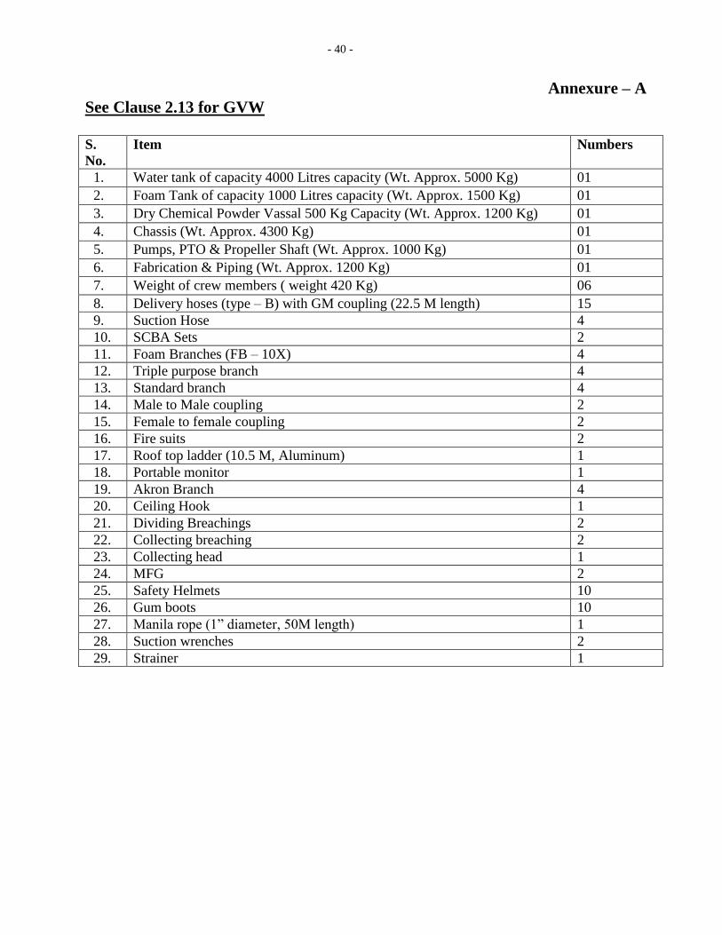
- 40 -
Annexure – A
See Clause 2.13 for GVW
S.
No.
Item Numbers
1. Water tank of capacity 4000 Litres capacity (Wt. Approx. 5000 Kg) 01
2. Foam Tank of capacity 1000 Litres capacity (Wt. Approx. 1500 Kg) 01
3. Dry Chemical Powder Vassal 500 Kg Capacity (Wt. Approx. 1200 Kg) 01
4. Chassis (Wt. Approx. 4300 Kg) 01
5. Pumps, PTO & Propeller Shaft (Wt. Approx. 1000 Kg) 01
6. Fabrication & Piping (Wt. Approx. 1200 Kg) 01
7. Weight of crew members ( weight 420 Kg) 06
8. Delivery hoses (type – B) with GM coupling (22.5 M length) 15
9. Suction Hose 4
10. SCBA Sets 2
11. Foam Branches (FB – 10X) 4
12. Triple purpose branch 4
13. Standard branch 4
14. Male to Male coupling 2
15. Female to female coupling 2
16. Fire suits 2
17. Roof top ladder (10.5 M, Aluminum) 1
18. Portable monitor 1
19. Akron Branch 4
20. Ceiling Hook 1
21. Dividing Breachings 2
22. Collecting breaching 2
23. Collecting head 1
24. MFG 2
25. Safety Helmets 10
26. Gum boots 10
27. Manila rope (1” diameter, 50M length) 1
28. Suction wrenches 2
29. Strainer 1

- 41 -
Annexure -B
Dry Chemical Powder Potassium Urea Based
1. General: The Powder shall be Potassium Allophonate / Carbonate based dry chemical powder, a
reaction product of Potassium Bicarbonate – Urea suitable for large scale high intensity flammable
oil & gas fire. The product should be UL Approved.
2. Physical & Chemical Parameters:
a. Appearance : Off-White free flowing powder
b. Particle Size : 50 – 70 microns
c. Apparent density : 0.5 - 0.7 gm/cc
d. Water Repellency : 1.5% Max
e. Moisture content : less than 0.25%(m/m)
f. Temperature stability : ± 60°C
3. Performance Test: Shall able to extinguish a 20B / 144B Hydrocarbon tray fire by filling 3.5 kg
(max) Powder in 5 kg extinguisher.
4. Physiological Effect:
a. The DCP shall not have harmful ingredients
b. It should be environmental friendly & nontoxic to humans and animals.
c. Should submit certificates of 1) Non-Toxicity 2) Non-Skin Irritation Test
5. Compatibility:
The DCP shall be compatible with all type of firefighting foams.
6. Approvals:
The Dry Chemical Powder (DCP) should be Listed/Approved by UL as per UL-299C on fire
extinguishing Dry Chemical for special application.
The dry powder should follow the latest Oil Industries Safety Directorate norms (OISD-116), as
mentioned in Section 12, Page No. 24.
7. Packing:
The DCP shall be packed in 25kg good quality HDPE drums which should be hermetically sealed.
8. Shelf Life:
DCP shall have minimum shelf life of 05 years without any degrading of chemical & physical
properties.
9 .Documents:
a. Must submit valid UL: 229C Certificate along with offer and supply.
b. Thermal Gravimetric Analysis (TGA) with decomposition between 215°C and 260°C
should be submitted of a reputed Lab along with the supply, IR analysis report as
conducted by UL to be also to be submitted along with the supply.
c. The bidder should submit ISO 9001:2008, ISO 14001: 2004 & OHSAS 18001:2007
certificate copies along with supply.
d. Warrantee / guarantee Certificate for the DCP along with supply.
e. MSDS of the material along with supply.
- 42 -
f. Original manufacturer test report along with supply.
g. Disposal Procedure for the material along with supply.
h. If the powder is imported the latest Bill of Lading is to be produced along with supply.
i. OIL reserves the right to send the sample from the supplied powder for further testing to
any authorized national laboratory in India.
10. MARKING:
Each container/drum containing Dry Chemical Powder shall be labelled with the following
information:
(a) Manufacturer’s name or trade mark.
(b) Quantity of the Powder, in Kg (Net and Gross weight)
(c) Type of the Powder and Foam Compatible.
(d) Date of manufacture/Batch No.
(e) UL Marking.
BID EVALUATION CRITERIA/BID REJECTION CRITERIA
The following BRC/BEC will govern the evaluation of the bids received against this tender. Bids that do not comply with stipulated BRC/BEC in full will be treated as non responsive and such bids shall prima-facie be rejected. Bid evaluation will be done only for those bids that pass through the “Bid Rejection Criteria” as stipulated in this document. Other terms and conditions of the enquiry shall be as per General Terms and Conditions vide MM/CALCUTTA/E-01/2010 for E-Procurement LCB Tenders. However, if any of the Clauses of the Bid Rejection Criteria / Bid Evaluation Criteria (BRC / BEC) contradict the Clauses of the tender or MM/CALCUTTA/E-01/2010 elsewhere, those in the BRC / BEC shall prevail. BID REJECTION CRITERIA (BRC): The bids shall conform generally to the specifications and terms as well as conditions laid out in the tender. Bids will be rejected in case the items offered do not conform to the required parameters stipulated in the technical specifications and to the respective international/national standards wherever stipulated. Notwithstanding the general conformity of the bids to the stipulated specifications and terms and conditions, the following requirements will have to be met by the bids, without which, the same shall be considered as non-responsive and stand rejected.
- 43 -
A-TECHNICAL
Bid should be complete in all aspect covering the entire scope of supply and should conform to the technical specifications indicated in the bid documents duly supported with technical catalogues/ literatures. Incomplete and non-conforming bids will be rejected outright.
1.0 BIDDER’S QUALIFICATION
The bidder shall be a "Fabricator / Assembler" of "Fire Water Tender/ Foam Tender/DCP Tender /Foam Nurser or Multi-purpose Fire Tender (i.e. combination of Water, Foam & DCP Tender). Copy of "Certificate of Incorporation" / "NSIC" certificate of the firm shall be furnished along with the bid.
2.0 BIDDER'S EXPERIENCE The bidder should have the experience of successful execution of supply of at least 01 (one) no. of “Fire Water Tender/ Foam Tender/DCP Tender or Multi-purpose Fire Tender (i.e. combination of Water, Foam & DCP Tender) on minimum 16 Tone Chassis capacity in the last 03 (three) years preceding to the Bid Closing date of this Tender. Copy of Purchase Order and Commissioning report /Performance report/ Proof of Supply should be enclosed along with bid to ascertain the same. 3.0 FINANCIAL: 3.1 The Annual financial turnover of the firm in any of the last 03 financial years or current financial year should not be less than Rs 247.43 lacs. In support of annual financial turnover, any one of the following documents/photocopies (self attested/attested) must be submitted along with the bid: ► A certificate issued by a practicing chartered/cost accountants firm with membership no. certifying the annual turnover and nature of business. ► Audited balance sheet and profit & loss account. 4.0 The bid/ offer shall be for complete unit i.e. chassis along with fabrication & commissioning of Multipurpose Fire Tender. B:COMMERCIAL
i) Bids are invited under Single Stage Two Bid System. Bidders shall quote accordingly under Single Stage Two Bid System. Please note that no price details should be furnished in the Technical (i.e. Unpriced) bid. The “Unpriced Bid” shall contain all techno-commercial details except the prices, which shall be kept blank. The “Price Bid” must contain the price schedule and the bidder’s commercial terms and conditions.
Bidder not complying with above submission procedure will be rejected.
- 44 -
ii) Bid security in the form of Demand Draft / Bank Guarantee as per format given in the LCB booklet MM/CALCUTTA/E-01/2010 of Rs 2,47,500.00 shall be submitted manually in sealed envelope superscribed with BID SECURITY AGAINST Tender no. SKI9254P16 dated 16.11.2015 to Head Calcutta Branch, Oil India Limited, 4 India Exchange Place, Kolkata - 700001 only on or before the Bid Closing Date and Time mentioned in the Tender. If bid security in ORIGINAL of above mentioned amount is not received within bid closing date , the bid submitted through electronic form will be rejected without any further consideration. In lieu, Bid Security of Rs. 2,47,500.00 can also be paid online through our e-procurement portal as per procedure given in user manual in OIL”s e-procurement portal.
For exemption for submission of Bid Security, please refer relevant para of General Terms and Conditions vide MM/CALCUTTA/E-01/2010 for E-Procurement LCB Tenders. The Bid Security shall be valid for 180 days more than the Bid validity, i.e., for 300 days from the date of bid opening.
iii) Bidders must confirm that Goods, materials or plant(s) to be supplied shall be new of recent make and of the best quality and workmanship and shall be guaranteed for a period of twelve months from the date of successful commissioning against any defects arising from faulty materials, workmanship or design. Defective goods/materials or parts rejected by OIL shall be replaced immediately by the supplier at the supplier’s expenses and no extra cost to OIL.
iv) The prices offered will have to be firm through delivery and not subject to variation on any account. A bid submitted with an adjustable price will be treated as non-responsive and rejected.
v) Successful bidder will be required to furnish a Performance Bank Guarantee @10% of the order value. For exemption for submission of Performance Bank Guarantee, please refer relevant para of General Terms and Conditions vide MM / CALCUTTA / E-01 / 2010 for E – Procurement LCB Tenders. The Performance Bank Guarantee must be valid for one year from the date of successful commissioning of the equipment or 18 months from the date of despatch whichever is earlier. Bidder must confirm the same in their bid.
Offers not complying with this clause will be rejected.
The validity requirement of Performance Security is assuming despatch within stipulated delivery period and confirmation to all terms and conditions of order. In case of any delay in despatch or non-confirmation to all terms and conditions of order, validity of the Performance Security is to be extended suitably as advised by OIL. The Bank Guarantee should be allowed to be encashed at all branches within India.
- 45 -
vi). Bids received after the bid closing date and time will be rejected. Similarly, modifications to bids received after the bid closing date & time will not be considered.
vii). Validity of the bid shall be minimum 120 days from the Bid Closing Date. Bids with
lesser validity will be rejected. viii). Bids containing incorrect statement will be rejected.
ix). All the Bids must be Digitally Signed using “Class 3” digital certificate (e-commerce application) as per Indian IT Act obtained from the licensed Certifying Authorities operating under the Root Certifying Authority of India (RCAI), Controller of Certifying Authorities (CCA) of India. The bid signed using other than “Class 3” digital certificate, will be rejected.
x). INTEGRITY PACT:
OIL shall be entering into an Integrity Pact with the bidders as per format enclosed with the tender document. This Integrity Pact proforma has been duly signed digitally by OIL’s competent signatory. The proforma has to be returned by the bidder (along with the technical bid) duly signed (digitally) by the same signatory who signed the bid, i.e., who is duly authorized to sign the bid. Any bid not accompanied by Integrity Pact Proforma duly signed (digitally) by the bidder shall be rejected straightway. Uploading the Integrity Pact with digital signature will be construed that all pages of the Integrity Pact has been signed by the bidder’s authorized signatory who sign the Bid.
C. GENERAL: i) The Compliance statement must be filled up by bidders and to be
submitted/uploaded along with their bids. In case bidder takes exception to any
clause of the bidding document not covered under BEC/BRC, then the Company
has the discretion to load or reject the offer on account of such exception if the
bidder does not withdraw/modify the deviation when/as advised by Company. The
loading so done by the company will be final and binding on the bidders.
ii) If any of the clauses in the BRC contradicts with other clauses of bidding
document elsewhere, then the clauses in the BRC shall prevail.
2.0 BID EVALUATION CRITERIA (BEC):
A. TECHNICAL:
The bids conforming to the technical specifications, terms and conditions stipulated in the
bidding document and considered to be responsive after subjecting to Bid Rejection
Criteria (BRC) will be considered for further evaluation as per the Bid Evaluation Criteria
given below.
i) In the event of computational error between unit rate and total price, the unit rate as
quoted by the bidder shall prevail.
- 46 -
ii) Similarly in the event of discrepancy between words and quoted figure, words will
prevail.
iii) Evaluation will be done on ‘total contract cost’ basis to ascertain the lowest bid.
B. COMMERCIAL:
i) To evaluate the inter-se-ranking of the offers, Assam entry tax on purchase value
will be loaded as per prevailing Govt. of Assam guidelines as applicable on bid
closing date.
Bidders may check this with the appropriate authority while submitting their offer.
ii) To ascertain the substantial responsiveness of the bid OIL reserves the right to
ask the bidder for clarification in respect of clauses covered under BRC also and
such clarifications fulfilling the BRC clauses in to must be received on or before
the dead line given by the company, failing which the offer will be summarily
rejected.
iii) To ascertain the inter-se-ranking, the comparison of the responsive bids will be
made as under, subject to corrections / adjustments given herein:
(A) Total material cost of Main Equipment: (B) Total cost of tools/tackles/accessories/mandatory spares/ repair kit for commissioning (C) Total Material Cost,( A+B ) (D) Total cost of fabrication (E) Packing and Forwarding Charges (F) Total Ex-works value, ( C+D+E ) above : (G) Excise Duty including Cess (H) Sales Tax, (Please indicate applicable rate of Tax) (I) Total FOR Despatching station price, ( F+G+H ) above (J) TPI Charges including Service Tax (K) Road Transportation charges to Duliajan (L) Insurance Charges @0.5% of Total For Despatching StationValue (I) above (M) Assam Entry Tax (N) Total FOR Duliajan value, (I+J+K+L+M) above (O) Installation/Commissioning Charges including Service Tax, if any : (P) Training Charges including Service Tax, if any : (Q) Grand Total value, (N+O+P)
Standard Notes:
A. The original bid security (Amount is mentioned above and also in Basic Data of the tender in OIL’s e-portal) should reach us before bid closing date and time. Bid without original Bid Security will be rejected (except for the bidders who has paid the same online). The bidders who are exempted from submitting the Bid Bond should attach documentary evidence in the Collaboration folder as per General Terms and conditions for e-Procurement
- 47 -
as per Booklet NO. MM/CALCUTTA/E-01/2010 for E-procurement (LCB Tenders).
B. “General Terms & Conditions” for e-Procurement as per Booklet NO. MM/CALCUTTA/E-01/2010 for E-procurement (LCB Tenders).
-----xxxx-----