Embed Size (px)
Citation preview
1
FORTY-PLUS YEARS OF HOVERCRAFT DEVELOPMENT
By
David R. Lavis Band, Lavis & Associates, Inc. Severna Park, Maryland, USA
David Lavis is the CEO of Band, Lavis & Associ-ates, Inc. of Severna Park, Maryland. He was educated in England and began his professional career in air cushion vehicles and hydrofoils with Saunders-Roe in 1959. Here, Mr. Lavis worked on many aspects of research, design, and con-struction of fast commercial ferries and military craft. In 1966, he received a Master of Science degree from Cranfield Institute of Technology and in early 1967, immigrated to join Bell Aerosys-tems, Buffalo, New York where he was engaged in the early design work for the U.S. Navy’s 100 mph SES-100B and the Amphibious Assault Craft JEFF(B). Mr. Lavis then joined the Aerojet Gen-eral Corporation in Sacramento, California and in 1972, was appointed manager of technology for their Marine Division. Here he worked on the SES-100B, JEFF(A) and 2K/3KSES programs. In 1977, he formed Band, Lavis & Associates, Inc., a company specializing in the design of advanced marine craft and systems. Mr. Lavis has pub-lished numerous papers on advanced craft. He is a Fellow of the Royal Institution of Naval Archi-tects and a Chartered Engineer in the United Kingdom. He also has membership with SNAME, ASNE, the International Hydrofoil Society and the UK and U.S. Hovercraft Societies. ABSTRACT
The paper discusses the current world-wide state of development of hovercraft including Air Cush-ion Vehicles (ACVs) and Surface Effect Ship (SES) in their commercial and military applica-tions. Included are accounts of developments of historical importance, with descriptions of current designs and subsystem technologies. Technolo-gies discussed include those concerned with hull structure, resistance, propulsion, cushion seals, lift systems, stability, wake, seakeeping and ma-neuvering. After more than 40 years of dedicated develop-ment, the design and construction capabilities can be considered mature. While much of the tech-nology was developed in North America, Europe
and the Far East have established the competitive viability of commercial applications. The military applications have been well recog-nized here and in both Europe and Russia and perhaps it is not too late for North America to also realize the commercial potential of the ACV and SES technology that we helped to introduce. 1.0 INTRODUCTION Air cushion supported craft, referred to as hover-craft, include amphibious Air Cushion Vehicles (ACVs) and non-amphibious Surface Effect Ships (SES). After more than 40 years of dedicated de-velopment, hovercraft technology can now be considered to be mature. The established tech-niques for design, performance prediction and model testing are credible and reasonably well documented. This development has occurred during the period of extensive expansion in elec-tronic computers and computational techniques that have benefited our understanding of the technology of both conventional and advanced craft alike. Thus, both conventional and advanced craft have emerged from the dark ages together. Although variants and hybrids have been suc-cessfully demonstrated, least risk hullforms or configurations have been established for both ACVs and SES. A consistent pattern for the se-lection of seals, lift systems, and propulsors has emerged, while the feasibility of steel, aluminum and single-skin or cored FRP construction has been amply demonstrated. The U.S. Navy’s program for the quantity produc-tion of Landing Craft, Air Cushion (LCACs) is a good example of ACV technology that has been successfully applied. Here the ACV was chosen to perform a function for the Marine Corps that virtually no other craft could perform. Similar ex-amples exist with the Canadian Coast Guard’s use of SR.N6s and AP.1-88 ACVs, and the UK’s SR.N4 cross-channel ferries which have been in service for 30 years.
2
The recent examples of ACV technology, the ABS M10, the Textron C-7, the Griffon 400TD and the Westland Dash 400 are clearly very impressive examples of where the development has taken us. Similarly, for SES has been the success of the Hovermarine HM series of passenger ferries of which over 100 were built. Focus for SES today is more towards larger sizes with the Royal Norwe-gian navy’s MCM vessels and Japan’s Techno Superliner, TSL A70 leading the way. However, in proposing applications, military or commercial, risks must be realistically assessed. Today, state-of-the-art is 1500 tons displacement for SES. Based on world experience, it would be reason-able to propose development of military or com-mercial SES, of up to 20,000 tons if the design and all components are essentially state-of-the-art and the potential benefits, economic or military, justify the risk associated with simply increasing size (and cost). SES and ACVs can achieve very high speeds economically. This is possible because of the much lower power required for such speeds com-pared to conventional craft, but this entails a somewhat higher initial cost. This economy of operation will improve further as the size of these craft increases. 2.0 HISTORY OF CRAFT DEVELOPMENT 2.1 Early Endeavors There have been numerous attempts over the years to utilize pressurized air, in one form or an-other, to reduce the resistance of marine vessels and land vehicles. Many of these attempts have been documented by way of patents. Some of these were reduced to practice with varying de-grees of success. Some were in the form of im-provements made on the works of earlier inven-tors while others were isolated developments that faultered often due to a lack of funding. Table 1 is a list of some of the more significant inventions derived from a patent search of prior art or otherwise derived from the information re-ported in References 1 through 12. The dates shown are the dates of the first application of the patent in each case. Therefore, several, if not many, years of development would have likely to have taken place before the date shown for the inventor’s first patent in each case.
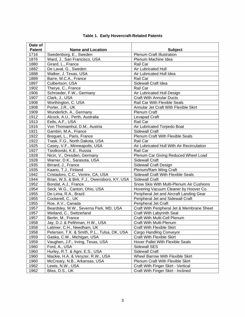
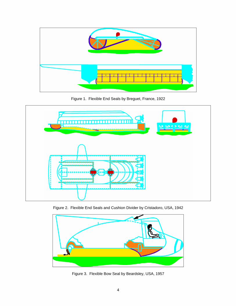
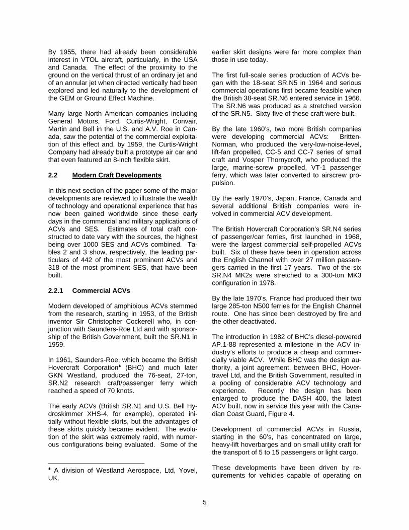
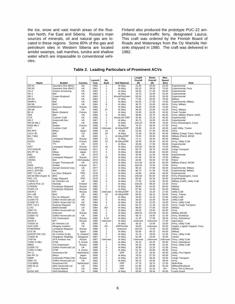
The earliest entry in this table is 1716 and there are a total of 30 entries preceding the significant pioneering developments of Sir Christopher Cockerell which were the impetus for modern de-velopment and which were first patented in 1955. Not all of the inventors are listed here (Table 1), since many did not patent their hovercraft or air lubricated hull ideas. Names such as Ivanov (1853), Froude (1865), Kabachinski, Labshin, Loitsyanski, Fedyaevski, Tsiolkovski (1927), Levkov (1927), & Turkin (1953) have been men-tioned (Reference 12) in this regard and add an-other nine to the list of 30 occurring before 1955. Perhaps, some of the more intriguing contribu-tions were those that featured flexible seals or skirts to help contain the cushion of pressurized air. There were at least eight inventors, starting in 1908 as shown in Table 1, who had this idea long before the British SR.N1 was fitted with a flexible seal in 1960. Of, perhaps, particular interest are the patents by Worthington, USA, 1908; Porter, UK, 1908, Breguet, France, 1922; and Cristadoro, USA, 1942. Worthington (U.S. Patent 936,395) described an air cushion support for a streetcar and used “flexi-ble” end seals to contain the air cushion at the front and rear of the car. Porter (U.S. Patent 1,123,589) on the other hand, devised a flying machine with an inflated flexible peripheral curtain to surround and trap air supplied to the underside of the machine. Breguet (British Patents 187,627 and 193,005) also used flexible fore and aft seals to trap pumped air for a double hull/fuselage flying boat to assist take-off and landing over land and water. The arrangement is illustrated in Figures 1 and 2. Cristadaro, out of Ventre, California, (U.S. Patent 2,322,790) also presented a vehicle with flexible end seals. In this case, it was an air-screw-propelled marine vehicle with rigid sidehulls that also featured an inflatable transverse flexible seal amidships to divide the cushion and improve longitudinal stability. The inflated bow seal was also said to protect the hullform from slamming loads. The description given about the opera-tional behavior of the vessel in calm and rough water would strongly suggest that the concept had actually been reduced to practice. Others who considered flexible seals included Fletcher, USA, 1953; Beardsley, USA, 1957 (U.S. Patent 3,342,280), Figure 3; Bertelsen, USA, 1958, Reference 11; and McCreary, USA, 1960 (U.S. Patent 3,532,179).
3
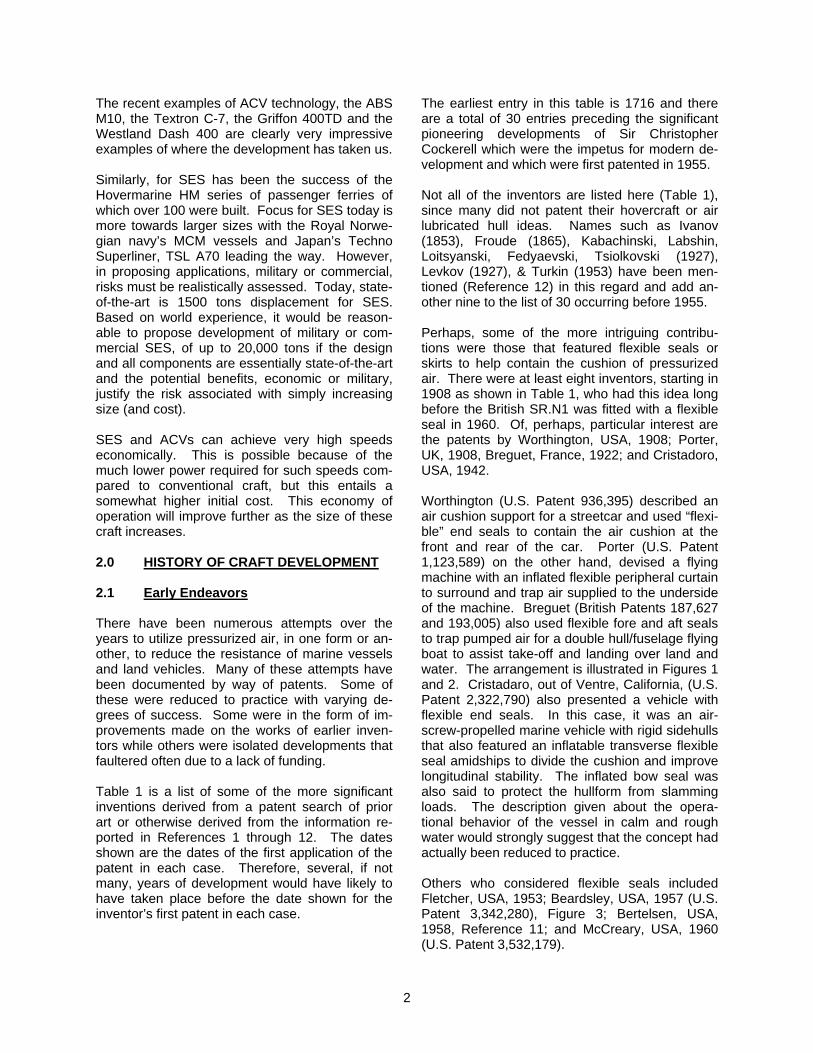
Table 1. Early Hovercraft-Related Patents
Date of Patent
Name and Location
Subject
1716 Swedenborg, E., Sweden Plenum Craft Illustration 1876 Ward, J., San Francisco, USA Plenum Machine Idea 1880 Girard, L., France Rail Car 1882 De Laval, G., Sweden Air Lubricated Hull 1888 Walker, J. Texas, USA Air Lubricated Hull Idea 1889 Barre, M.C.A., France Rail Car 1897 Culbertson, USA Sidewall Craft Idea 1902 Therye, C., France Rail Car 1906 Schroeder, F.W., Germany Air Lubricated Hull Design 1907 Clark, J., USA Craft With Annular Ducts 1908 Worthington, C. USA Rail Car With Flexible Seals 1908 Porter, J.R., UK Annular Jet Craft With Flexible Skirt 1909 Wunderlich, A., Germany Plenum Craft 1912 Alcock, A.U., Perth, Australia Levapad Craft 1913 Eells, A.F., USA Rail Car 1916 Von Thomamhul, D.M., Austria Air Lubricated Torpedo Boat 1921 Gambin, M.A., France Sidewall Craft 1922 Breguet, L., Paris, France Plenum Craft With Flexible Seals 1922 Trask, F.G., North Dakota, USA Rail Car 1925 Casey, V.F., Minneapolis, USA Air Lubricated Hull With Air Recirculation 1927 Tsiolkovski, K.E., Russia Rail Car 1928 Nicin, V., Dresden, Germany Plenum Car Giving Reduced Wheel Load 1928 Warner, D.K., Sarasota, USA Sidewall Craft 1935 Birrard, J., France Sidewall Craft Design 1935 Kaario, T.J., Finland Plenum/Ram Wing Craft 1942 Cristadoro, C.C., Ventre, CA, USA Sidewall Craft With Flexible Seals 1944 Brian, W.S. & Birk, F.J., Owensboro, KY, USA Sidewall Craft 1952 Bondat, A.J., France Snow Skis With Multi-Plenum Air Cushions 1954 Seck, W.G., Canton, Ohio, USA Hovering Vacuum Cleaner by Hoover Co. 1955 De Lima, R.A., Brazil Peripheral Jet and Aircraft Landing Gear 1955 Cockerell, C., UK Peripheral Jet and Sidewall Craft 1955 Roe, A.V., Canada Peripheral Jet Craft 1957 Beardsley, M.W., Severna Park, MD, USA Craft With Peripheral Jet & Membrane Sheet 1957 Weiland, C., Switzerland Craft With Labyrinth Seal 1957 Bertin, M., France Craft With Multi-Cell Plenum 1958 Jay, D.J. & Pelthman, H.W., USA Craft With Multi-Plenum 1958 Latimer, C.H., Needham, UK Craft With Flexible Skirt 1958 Petersen, T.K. & Smith, P.L., Tulsa, OK, USA Cargo Handling Conveyor 1959 Gaska, C.W., Michigan, USA Craft With Flexible Skirt 1959 Vaughen, J.F., Irving, Texas, USA Hover Pallet With Flexible Seals 1960 Ford, A., USA Sidewall SES 1960 Hurley, R.T. & Agni, E.S., USA Sidewall Craft 1960 Mackie, H.A. & Veryzer, R.W., USA Wheel Barrow With Flexible Skirt 1960 McCreary, N.B., Arkansas, USA Plenum Craft With Flexible Skirt 1962 Lewis, N.W., USA Craft With Finger Skirt - Vertical 1962 Bliss, D.S., UK Craft With Finger Skirt - Inclined
4
Figure 1. Flexible End Seals by Breguet, France, 1922
Figure 2. Flexible End Seals and Cushion Divider by Cristadoro, USA, 1942
Figure 3. Flexible Bow Seal by Beardsley, USA, 1957
5
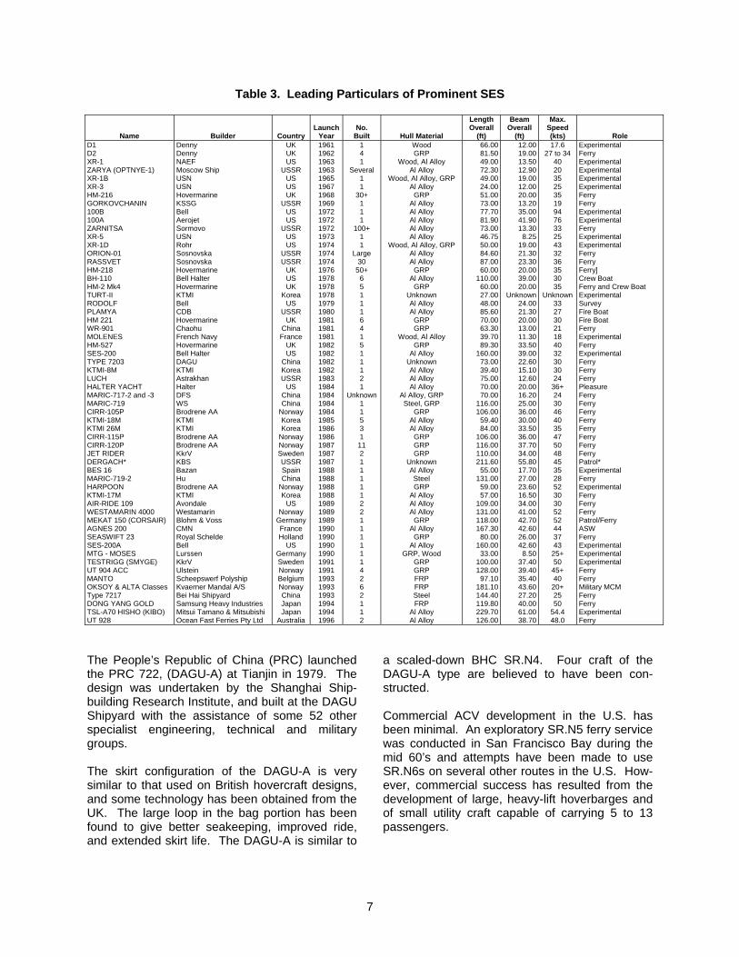
By 1955, there had already been considerable interest in VTOL aircraft, particularly, in the USA and Canada. The effect of the proximity to the ground on the vertical thrust of an ordinary jet and of an annular jet when directed vertically had been explored and led naturally to the development of the GEM or Ground Effect Machine. Many large North American companies including General Motors, Ford, Curtis-Wright, Convair, Martin and Bell in the U.S. and A.V. Roe in Can-ada, saw the potential of the commercial exploita-tion of this effect and, by 1959, the Curtis-Wright Company had already built a prototype air car and that even featured an 8-inch flexible skirt. 2.2 Modern Craft Developments In this next section of the paper some of the major developments are reviewed to illustrate the wealth of technology and operational experience that has now been gained worldwide since these early days in the commercial and military applications of ACVs and SES. Estimates of total craft con-structed to date vary with the sources, the highest being over 1000 SES and ACVs combined. Ta-bles 2 and 3 show, respectively, the leading par-ticulars of 442 of the most prominent ACVs and 318 of the most prominent SES, that have been built. 2.2.1 Commercial ACVs Modern developed of amphibious ACVs stemmed from the research, starting in 1953, of the British inventor Sir Christopher Cockerell who, in con-junction with Saunders-Roe Ltd and with sponsor-ship of the British Government, built the SR.N1 in 1959. In 1961, Saunders-Roe, which became the British Hovercraft Corporation (BHC) and much later GKN Westland, produced the 76-seat, 27-ton, SR.N2 research craft/passenger ferry which reached a speed of 70 knots. The early ACVs (British SR.N1 and U.S. Bell Hy-droskimmer XHS-4, for example), operated ini-tially without flexible skirts, but the advantages of these skirts quickly became evident. The evolu-tion of the skirt was extremely rapid, with numer-ous configurations being evaluated. Some of the
A division of Westland Aerospace, Ltd, Yovel,
UK.
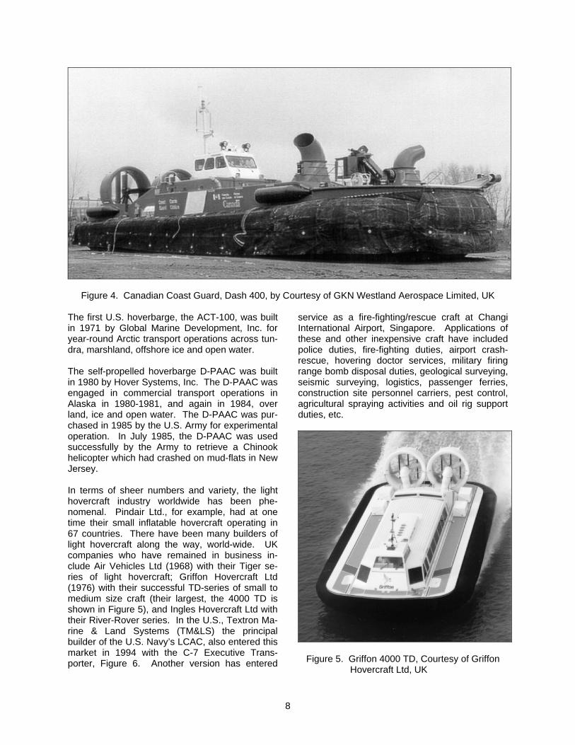
earlier skirt designs were far more complex than those in use today. The first full-scale series production of ACVs be-gan with the 18-seat SR.N5 in 1964 and serious commercial operations first became feasible when the British 38-seat SR.N6 entered service in 1966. The SR.N6 was produced as a stretched version of the SR.N5. Sixty-five of these craft were built. By the late 1960’s, two more British companies were developing commercial ACVs: Britten-Norman, who produced the very-low-noise-level, lift-fan propelled, CC-5 and CC-7 series of small craft and Vosper Thornycroft, who produced the large, marine-screw propelled, VT-1 passenger ferry, which was later converted to airscrew pro-pulsion. By the early 1970’s, Japan, France, Canada and several additional British companies were in-volved in commercial ACV development. The British Hovercraft Corporation’s SR.N4 series of passenger/car ferries, first launched in 1968, were the largest commercial self-propelled ACVs built. Six of these have been in operation across the English Channel with over 27 million passen-gers carried in the first 17 years. Two of the six SR.N4 MK2s were stretched to a 300-ton MK3 configuration in 1978. By the late 1970’s, France had produced their two large 285-ton N500 ferries for the English Channel route. One has since been destroyed by fire and the other deactivated. The introduction in 1982 of BHC’s diesel-powered AP.1-88 represented a milestone in the ACV in-dustry’s efforts to produce a cheap and commer-cially viable ACV. While BHC was the design au-thority, a joint agreement, between BHC, Hover-travel Ltd, and the British Government, resulted in a pooling of considerable ACV technology and experience. Recently the design has been enlarged to produce the DASH 400, the latest ACV built, now in service this year with the Cana-dian Coast Guard, Figure 4. Development of commercial ACVs in Russia, starting in the 60’s, has concentrated on large, heavy-lift hoverbarges and on small utility craft for the transport of 5 to 15 passengers or light cargo. These developments have been driven by re-quirements for vehicles capable of operating on
6
the ice, snow and vast marsh areas of the Rus-sian North, Far East and Siberia. Russia’s main sources of minerals, oil and natural gas are lo-cated in these regions. Some 80% of the gas and petroleum sites in Western Siberia are located amidst swamps, salt marshes, tundra and shallow water which are impassable to conventional vehi-cles.
Finland also produced the prototype PUC-22 am-phibious mixed-traffic ferry, designated Laurus. This craft was ordered by the Finnish Board of Roads and Waterways from the Oy Wartsila Hel-sinki shipyard in 1980. The craft was delivered in 1982.
Table 2. Leading Particulars of Prominent ACVs
Name
Builder
Country
Launch
Year
No.
Built
Hull Material
Length Overall
(ft)
Beam Overall
(ft)
Max. Speed (kts)
Role SR.N1 SR.N2 VA-3 SK-3 HD-1 SR.N3 SKMR-1 SR.N5 SORMOVICH SR.N6 BC-8 SK5 CC5 HD-2 SR.N4 Mk 2 N300 Mk II CC7 MV-PP5 LACV-30 BH-7 Mk2 GUS N102C T4 AIST VOYAGEUR MV-PP 15 EM2 LEBED VIKING VT2 N500 AALC JEFF(A) AALC JEFF(B) PRC 711-IIA SR.N4 Mk3 (Super 4) PRC 722 TIGER 12 LARUS PUC 22 UTENOK TSAPLYA SAVR-2 AP.1-88 PRC 7210 G1000 TD G1500 TD PRC 716 II LCAC 2500 TD PELIKAN G2500 TD PUMA SAVR-3 TIGER 16 SAH 2200 POMORNIK VCA 36 SURVEYOR 12D TIGER 40 TAIFUN TURK IV Mk1 IRBIS G2000 TD TURK IV Mk2 PH 11 MV-PP 10 SIBIR 4000 TD COLIBRIE ABS M-10 C-7 DASH 400
Saunders Roe (BHC) Saunders Roe (BHC) Vickers Armstrong Bell Cowes Boatyard BHC Bell BHC Sormovo Shipyard BHC Bertin (Sedam) Bell Cushion Craft Hovercraft Dev. BHC Sedam Cushion Craft Mitsui Bell BHC Leningrad Shipyard Sedam TTI Leningrad Shipyard Bell Mitsui Enfield Leningrad Shipyard Bell Vosper Thorneycroft Sedam Aerojet General Corp. Bell Liu Zhou Shipyard BHC Dagu Shipyard Air Vehicles Ltd Wartsila Feodosiya Shipyard Feodosiya Shipyard MTI BHC Wu Hu Shipyard Griffon Hovercraft Ltd Griffon Hovercraft Ltd Hudong Shipyard Bell/Avondale Griffon Hovercraft Ltd Unknown Griffon Hovercraft Ltd V/O Sudoexport MTI Air Vehicles Ltd Slingsby Aviation Leningrad Shipyard Chaconsa Air Cushion Enter. Singapore Shipbldg UFA Aviation Inst. KTMI V/O Sudoexport Griffon Hovercraft Ltd KTMI Hovertrans BV Mitsui Gorkavski Philial CNII Griffon Hovercraft Ltd Hovertrans BV ABS Hovercraft Ltd Textron Marine GKN Westland
UK UK UK US UK UK US UK
Russia UK
France US UK UK UK
France UK
Japan US UK
Russia France
US Russia Canada Japan
UK Russia
US/Canada UK
France US US
PRC UK
PRC UK
Finland Russia Russia Russia
UK PRC UK UK
PRC US UK
Russia UK
Russia Russia
UK UK
Russia Spain
N. Zealand Singapore
Russia S. Korea Russia
UK S. Korea
Netherland Japan Russia
UK Netherland
UK US UK
1959 1961 1962 1963 1963 1963 1963 1964 1965 1965 1965 1966 1966 1967 1968 1968 1968 1968 1969 1969 1969 1969 1970 1970 1971 1972 1973 1973 1974 1975 1977 1977 1977 1978 1978 1979 1980 1981 1982 1982 1982 1982 1983 1983 1984 1984 1984 1985 1985 1985 1985 1985 1985 1986 1986 1986 1986 1987 1987 1988 1988 1989 1989 1990 1990 1990 1992 1993 1994 1994 1998
1 1 1 1 1 1 1 8 1
57 1 6 1 1 4 2
Unknown19 26 1
31 10 1
16 4 4 1
35 1 1 2 1 1 1 2 1 5 1 2 2
Unknown10 2 5 3 1
93+ 2 2 2
5-10 Unknown
3 25+
3 1 2 1
Unknown1 1 3 2 2 2 1 2 2 2 2 1
Al Alloy Al Alloy Al Alloy Al Alloy
Wood/Polyfoam Al Alloy Al Alloy Al Alloy Al Alloy Al Alloy Al Alloy Al Alloy
Wood,/Al/ GRP Al Alloy Al Alloy Al Alloy
Al Alloy/GRP Al Ally
Al Alloy Al Alloy/GRP
Al Alloy Al Alloy/GRP
Al Alloy Al Alloy Al Alloy Al Alloy Al Alloy Al Alloy Al Alloy Al Alloy Al Alloy Al Alloy Al Alloy Al Alloy Al Alloy Al Alloy Al Alloy Al Alloy Al Alloy Al Alloy
Al Alloy/GRP Al Alloy/GRP
Al Alloy Al Alloy Al Alloy Al Alloy Al Alloy Al Alloy Al Alloy Al Alloy Al Alloy Al Alloy Al Alloy
GRP/Kevlar Unknown Al Alloy Al Alloy Al Alloy Al Alloy Al Alloy Al Alloy Al Alloy Al Alloy
GRP Al Alloy Al Alloy Al Alloy
FRP FRP FRP
Al Alloy
31.40 65.25 55.00 18.70 50.00 77.00 65.50 38.75 96.00 48.40 33.00 38.83 30.30 30.75
130.20 76.10 25.80 52.50 76.30 78.33 72.11 33.50 35.00
155.00 65.70 86.60 40.00 81.40 44.50
101.00 164.00 96.10 86.70 43.60
185.00 89.30 27.00
108.30 88.90 87.90 33.10 80.00 34.50 28.20 34.30 60.70 88.00 49.20
288.40 48.70 41.25
Unknown 38.10 40.60
183.50 82.60 31.10 52.49
Unknown 45.10 59.16 35.80 51.70 37.20 78.10 82.70 58.70 37.70 61.80 52.50 93.50
25.00 29.50 27.00 16.00 23.00 30.50 27.00 23.00 32.80 23.00 16.50 23.75 15.20 19.00 78.00 36.40 15.20 27.30 36.30 45.50 26.40 25.30 17.50 65.00 36.70 45.60 21.00 35.40 26.00 43.50 75.50 47.80 47.00 19.60 92.00 45.30 13.00 48.20 44.00 44.00 15.20 36.10 15.20 15.00 15.00 11.20 47.00 23.00
144.90 19.50 17.58
Unknown 13.90
Unknown 72.00 36.20 18.00 19.69
Unknown 25.20 20.96 15.20 25.80 19.30 37.20 38.40 24.00 18.70 28.90 31.20 39.40
23.00 70.00 55.00 52.00 35.00 79.00 70.00 60.00 75.00 52.00 43.00 60.00 40.00 45.00 70.00 57.00 40.00 55.00 40.00 58.00 60.00 60.00 35.00 70.00 64.00 60.00 45.00 70.00 57.00 65.00 75.00 65.00 70.00 40.00 65.00 55.00 35.00 23.30 65.00 50.00 27.00 50.00 22.00 35.00 33.00 43.20 50.00 40.00 50.00 31.00 35.00 27.00 33.00 40.00 55.00 60.00 41.00 35.00
Unknown 50.00 31.00 31.00 40.00 40.00 50.00 43.00 38.00 37.00 50.00 40+
50.00
Experimental Experimental, Ferry Experimental Experimental Experimental Military Experimental, Military Ferry, Military Ferry Ferry, Military Crash Tender Ferry, Military (Patrol, SAR) Experimental Experimental Ferry (Passengers, Cars) Ferry Light Utility, Trainer Ferry Military (Cargo Trans, Patrol) Military (Patrol, MCM) Military Ferry, Utility Craft Experimental Military Cargo Transport Ferry Experimental Military Patrol Military (Patrol, MCM) Ferry Experimental, Military Experimental, Military Experimental Ferry (Passengers, Cars) Experimental Military (C&R), Utility Craft Ferry Military Military Utility Craft Ferry, Trainer Utility Craft Utility Craft Ferry, Utility Craft Ferry, Cargo Transport Military Ferry Military (MCM) Ferry, Workboat Ferry, Ambulance Agriculture Ferry, Utility Craft Supply, Logistic Support, Ferry Military Military Ferry, Utility Craft Varied Ferry, Utility Craft Ferry, Ambulance Ferry, Utility Craft Ferry Ferry Utility, Fire Fighter Ferry Cargo Transport Ferry Multi-Role Military/Workboat Ferry, Fire & Rescue Coast Guard
7
Table 3. Leading Particulars of Prominent SES
Name
Builder
Country
Launch
Year
No.
Built
Hull Material
Length Overall
(ft)
Beam Overall
(ft)
Max. Speed (kts)
Role D1 D2 XR-1 ZARYA (OPTNYE-1) XR-1B XR-3 HM-216 GORKOVCHANIN 100B 100A ZARNITSA XR-5 XR-1D ORION-01 RASSVET HM-218 BH-110 HM-2 Mk4 TURT-II RODOLF PLAMYA HM 221 WR-901 MOLENES HM-527 SES-200 TYPE 7203 KTMI-8M LUCH HALTER YACHT MARIC-717-2 and -3 MARIC-719 CIRR-105P KTMI-18M KTMI 26M CIRR-115P CIRR-120P JET RIDER DERGACH* BES 16 MARIC-719-2 HARPOON KTMI-17M AIR-RIDE 109 WESTAMARIN 4000 MEKAT 150 (CORSAIR) AGNES 200 SEASWIFT 23 SES-200A MTG - MOSES TESTRIGG (SMYGE) UT 904 ACC MANTO OKSOY & ALTA Classes Type 7217 DONG YANG GOLD TSL-A70 HISHO (KIBO) UT 928
Denny Denny NAEF Moscow Ship USN USN Hovermarine KSSG Bell Aerojet Sormovo USN Rohr Sosnovska Sosnovska Hovermarine Bell Halter Hovermarine KTMI Bell CDB Hovermarine Chaohu French Navy Hovermarine Bell Halter DAGU KTMI Astrakhan Halter DFS WS Brodrene AA KTMI KTMI Brodrene AA Brodrene AA KkrV KBS Bazan Hu Brodrene AA KTMI Avondale Westamarin Blohm & Voss CMN Royal Schelde Bell Lurssen KkrV Ulstein Scheepswerf Polyship Kvaerner Mandal A/S Bei Hai Shipyard Samsung Heavy Industries Mitsui Tamano & Mitsubishi Ocean Fast Ferries Pty Ltd
UK UK US
USSR US US UK
USSR US US
USSR US US
USSR USSR
UK US UK
Korea US
USSR UK
China France
UK US
China Korea USSR
US China China
Norway Korea Korea
Norway Norway Sweden USSR Spain China
Norway Korea
US Norway
GermanyFrance Holland
US GermanySweden Norway Belgium Norway China Japan Japan
Australia
1961 1962 1963 1963 1965 1967 1968 1969 1972 1972 1972 1973 1974 1974 1974 1976 1978 1978 1978 1979 1980 1981 1981 1981 1982 1982 1982 1982 1983 1984 1984 1984 1984 1985 1986 1986 1987 1987 1987 1988 1988 1988 1988 1989 1989 1989 1990 1990 1990 1990 1991 1991 1993 1993 1993 1994 1994 1996
1 4 1
Several 1 1
30+ 1 1 1
100+ 1 1
Large 30
50+ 6 5 1 1 1 6 4 1 5 1 1 1 2 1
Unknown1 1 5 3 1
11 2 1 1 1 1 1 2 2 1 1 1 1 1 1 4 2 6 2 1 1 2
Wood GRP
Wood, Al Alloy Al Alloy
Wood, Al Alloy, GRP Al Alloy
GRP Al Alloy Al Alloy Al Alloy Al Alloy Al Alloy
Wood, Al Alloy, GRP Al Alloy Al Alloy
GRP Al Alloy
GRP Unknown Al Alloy Al Alloy
GRP GRP
Wood, Al Alloy GRP
Al Alloy Unknown Al Alloy Al Alloy Al Alloy
Al Alloy, GRP Steel, GRP
GRP Al Alloy Al Alloy
GRP GRP GRP
Unknown Al Alloy Steel GRP
Al Alloy Al Alloy Al Alloy
GRP Al Alloy
GRP Al Alloy
GRP, Wood GRP GRP FRP FRP Steel FRP
Al Alloy Al Alloy
66.0081.5049.0072.3049.0024.0051.0073.0077.7081.9073.0046.7550.0084.6087.0060.00
110.0060.0027.0048.0085.6070.0063.3039.7089.30
160.0073.0039.4075.0070.0070.00
116.00106.00
59.4084.00
106.00116.00110.00211.60
55.00131.00
59.0057.00
109.00131.00118.00167.30
80.00160.00
33.00100.00128.00
97.10181.10144.40119.80229.70126.00
12.00 19.00 13.50 12.90 19.00 12.00 20.00 13.20 35.00 41.90 13.30 8.25
19.00 21.30 23.30 20.00 39.00 20.00
Unknown 24.00 21.30 20.00 13.00 11.30 33.50 39.00 22.60 15.10 12.60 20.00 16.20 25.00 36.00 30.00 33.50 36.00 37.70 34.00 55.80 17.70 27.00 23.60 16.50 34.00 41.00 42.70 42.60 26.00 42.60 8.50
37.40 39.40 35.40 43.60 27.20 40.00 61.00 38.70
17.6 27 to 34
40 20 35 25 35 19 94 76 33 25 43 32 36 35 30 35
Unknown 33 27 30 21 18 40 32 30 30 24
36+ 24 30 46 40 35 47 50 48 45 35 28 52 30 30 52 52 44 37 43
25+ 50
45+ 40
20+ 25 50
54.4 48.0
Experimental Ferry Experimental Experimental Experimental Experimental Ferry Ferry Experimental Experimental Ferry Experimental Experimental Ferry Ferry Ferry] Crew Boat Ferry and Crew Boat Experimental Survey Fire Boat Fire Boat Ferry Experimental Ferry Experimental Ferry Ferry Ferry Pleasure Ferry Ferry Ferry Ferry Ferry Ferry Ferry Ferry Patrol* Experimental Ferry Experimental Ferry Ferry Ferry Patrol/Ferry ASW Ferry Experimental Experimental Experimental Ferry Ferry Military MCM Ferry Ferry Experimental Ferry
The People’s Republic of China (PRC) launched the PRC 722, (DAGU-A) at Tianjin in 1979. The design was undertaken by the Shanghai Ship-building Research Institute, and built at the DAGU Shipyard with the assistance of some 52 other specialist engineering, technical and military groups. The skirt configuration of the DAGU-A is very similar to that used on British hovercraft designs, and some technology has been obtained from the UK. The large loop in the bag portion has been found to give better seakeeping, improved ride, and extended skirt life. The DAGU-A is similar to
a scaled-down BHC SR.N4. Four craft of the DAGU-A type are believed to have been con-structed. Commercial ACV development in the U.S. has been minimal. An exploratory SR.N5 ferry service was conducted in San Francisco Bay during the mid 60’s and attempts have been made to use SR.N6s on several other routes in the U.S. How-ever, commercial success has resulted from the development of large, heavy-lift hoverbarges and of small utility craft capable of carrying 5 to 13 passengers.
8
Figure 4. Canadian Coast Guard, Dash 400, by Courtesy of GKN Westland Aerospace Limited, UK
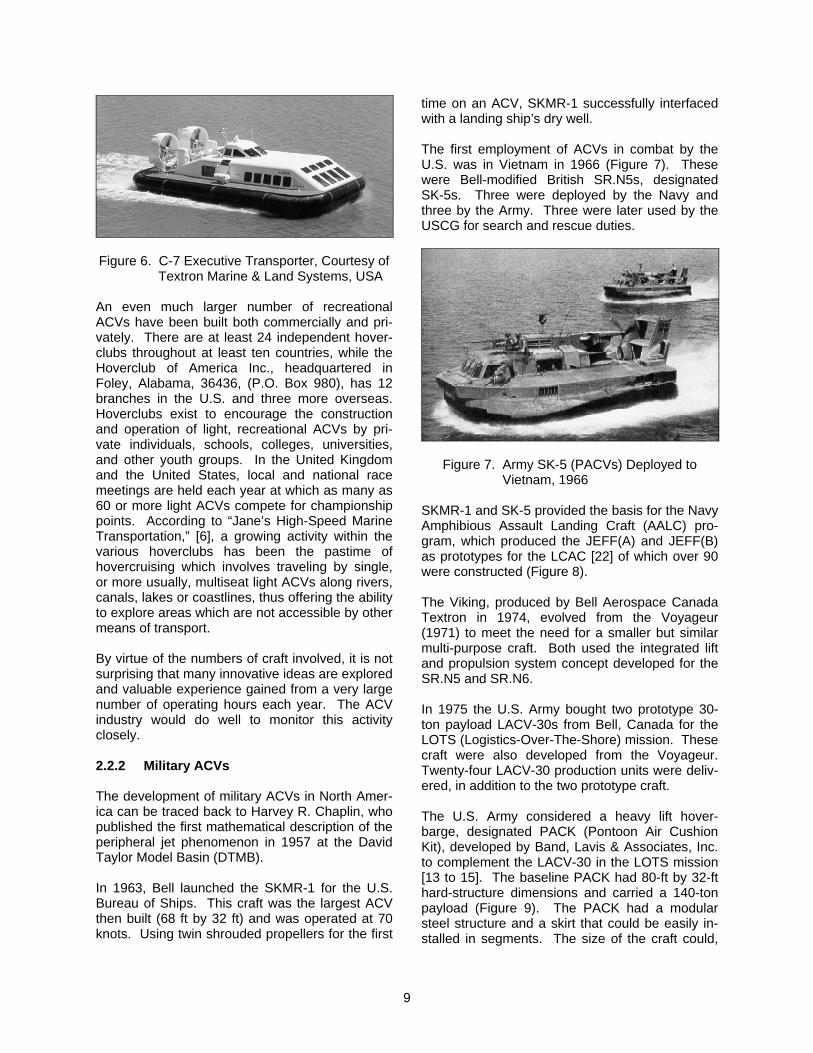
The first U.S. hoverbarge, the ACT-100, was built in 1971 by Global Marine Development, Inc. for year-round Arctic transport operations across tun-dra, marshland, offshore ice and open water. The self-propelled hoverbarge D-PAAC was built in 1980 by Hover Systems, Inc. The D-PAAC was engaged in commercial transport operations in Alaska in 1980-1981, and again in 1984, over land, ice and open water. The D-PAAC was pur-chased in 1985 by the U.S. Army for experimental operation. In July 1985, the D-PAAC was used successfully by the Army to retrieve a Chinook helicopter which had crashed on mud-flats in New Jersey. In terms of sheer numbers and variety, the light hovercraft industry worldwide has been phe-nomenal. Pindair Ltd., for example, had at one time their small inflatable hovercraft operating in 67 countries. There have been many builders of light hovercraft along the way, world-wide. UK companies who have remained in business in-clude Air Vehicles Ltd (1968) with their Tiger se-ries of light hovercraft; Griffon Hovercraft Ltd (1976) with their successful TD-series of small to medium size craft (their largest, the 4000 TD is shown in Figure 5), and Ingles Hovercraft Ltd with their River-Rover series. In the U.S., Textron Ma-rine & Land Systems (TM&LS) the principal builder of the U.S. Navy’s LCAC, also entered this market in 1994 with the C-7 Executive Trans-porter, Figure 6. Another version has entered
service as a fire-fighting/rescue craft at Changi International Airport, Singapore. Applications of these and other inexpensive craft have included police duties, fire-fighting duties, airport crash-rescue, hovering doctor services, military firing range bomb disposal duties, geological surveying, seismic surveying, logistics, passenger ferries, construction site personnel carriers, pest control, agricultural spraying activities and oil rig support duties, etc.
Figure 5. Griffon 4000 TD, Courtesy of Griffon Hovercraft Ltd, UK
9
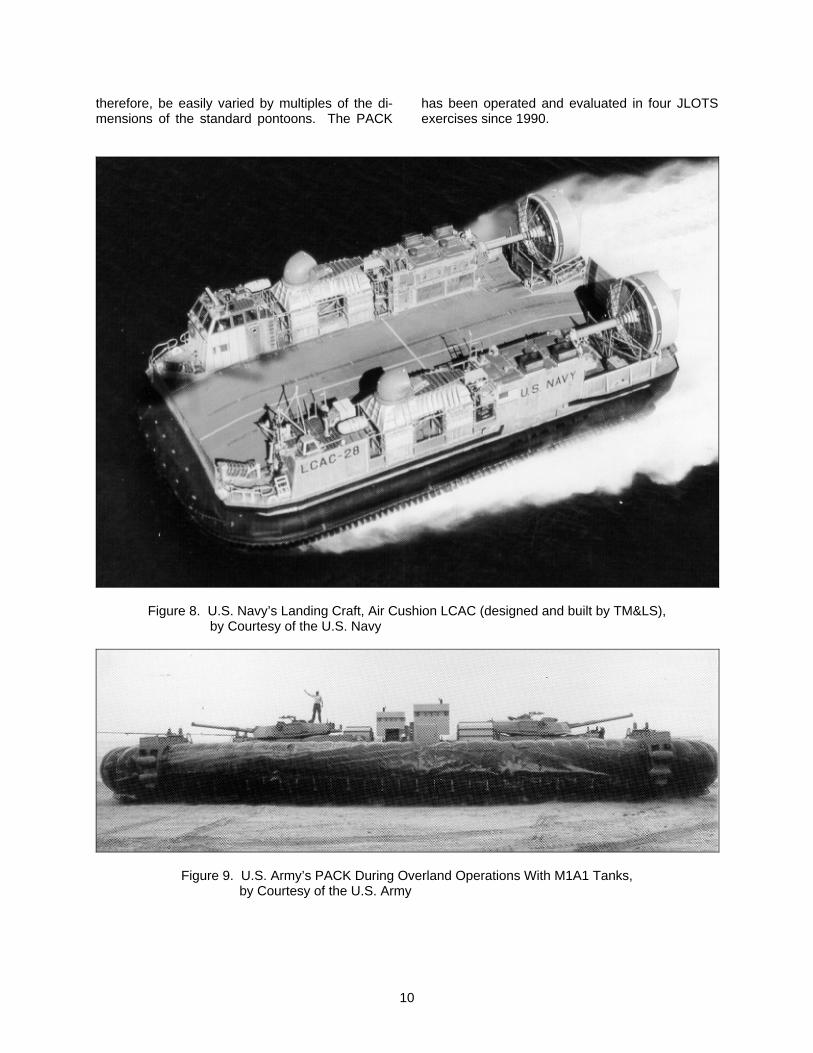
Figure 6. C-7 Executive Transporter, Courtesy of
Textron Marine & Land Systems, USA An even much larger number of recreational ACVs have been built both commercially and pri-vately. There are at least 24 independent hover-clubs throughout at least ten countries, while the Hoverclub of America Inc., headquartered in Foley, Alabama, 36436, (P.O. Box 980), has 12 branches in the U.S. and three more overseas. Hoverclubs exist to encourage the construction and operation of light, recreational ACVs by pri-vate individuals, schools, colleges, universities, and other youth groups. In the United Kingdom and the United States, local and national race meetings are held each year at which as many as 60 or more light ACVs compete for championship points. According to “Jane’s High-Speed Marine Transportation,” [6], a growing activity within the various hoverclubs has been the pastime of hovercruising which involves traveling by single, or more usually, multiseat light ACVs along rivers, canals, lakes or coastlines, thus offering the ability to explore areas which are not accessible by other means of transport. By virtue of the numbers of craft involved, it is not surprising that many innovative ideas are explored and valuable experience gained from a very large number of operating hours each year. The ACV industry would do well to monitor this activity closely. 2.2.2 Military ACVs The development of military ACVs in North Amer-ica can be traced back to Harvey R. Chaplin, who published the first mathematical description of the peripheral jet phenomenon in 1957 at the David Taylor Model Basin (DTMB). In 1963, Bell launched the SKMR-1 for the U.S. Bureau of Ships. This craft was the largest ACV then built (68 ft by 32 ft) and was operated at 70 knots. Using twin shrouded propellers for the first
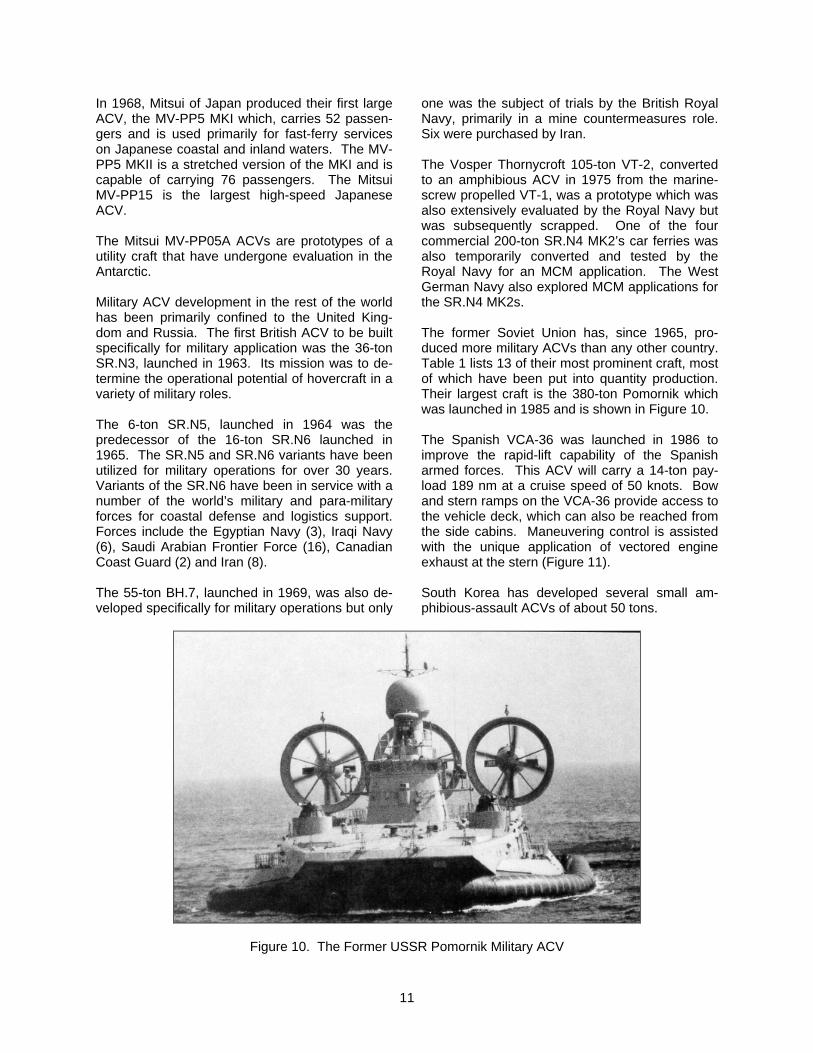
time on an ACV, SKMR-1 successfully interfaced with a landing ship’s dry well. The first employment of ACVs in combat by the U.S. was in Vietnam in 1966 (Figure 7). These were Bell-modified British SR.N5s, designated SK-5s. Three were deployed by the Navy and three by the Army. Three were later used by the USCG for search and rescue duties.
Figure 7. Army SK-5 (PACVs) Deployed to Vietnam, 1966
SKMR-1 and SK-5 provided the basis for the Navy Amphibious Assault Landing Craft (AALC) pro-gram, which produced the JEFF(A) and JEFF(B) as prototypes for the LCAC [22] of which over 90 were constructed (Figure 8). The Viking, produced by Bell Aerospace Canada Textron in 1974, evolved from the Voyageur (1971) to meet the need for a smaller but similar multi-purpose craft. Both used the integrated lift and propulsion system concept developed for the SR.N5 and SR.N6. In 1975 the U.S. Army bought two prototype 30-ton payload LACV-30s from Bell, Canada for the LOTS (Logistics-Over-The-Shore) mission. These craft were also developed from the Voyageur. Twenty-four LACV-30 production units were deliv-ered, in addition to the two prototype craft. The U.S. Army considered a heavy lift hover-barge, designated PACK (Pontoon Air Cushion Kit), developed by Band, Lavis & Associates, Inc. to complement the LACV-30 in the LOTS mission [13 to 15]. The baseline PACK had 80-ft by 32-ft hard-structure dimensions and carried a 140-ton payload (Figure 9). The PACK had a modular steel structure and a skirt that could be easily in-stalled in segments. The size of the craft could,
10
therefore, be easily varied by multiples of the di-mensions of the standard pontoons. The PACK
has been operated and evaluated in four JLOTS exercises since 1990.
Figure 8. U.S. Navy’s Landing Craft, Air Cushion LCAC (designed and built by TM&LS), by Courtesy of the U.S. Navy
Figure 9. U.S. Army’s PACK During Overland Operations With M1A1 Tanks, by Courtesy of the U.S. Army
11
In 1968, Mitsui of Japan produced their first large ACV, the MV-PP5 MKI which, carries 52 passen-gers and is used primarily for fast-ferry services on Japanese coastal and inland waters. The MV-PP5 MKII is a stretched version of the MKI and is capable of carrying 76 passengers. The Mitsui MV-PP15 is the largest high-speed Japanese ACV. The Mitsui MV-PP05A ACVs are prototypes of a utility craft that have undergone evaluation in the Antarctic. Military ACV development in the rest of the world has been primarily confined to the United King-dom and Russia. The first British ACV to be built specifically for military application was the 36-ton SR.N3, launched in 1963. Its mission was to de-termine the operational potential of hovercraft in a variety of military roles. The 6-ton SR.N5, launched in 1964 was the predecessor of the 16-ton SR.N6 launched in 1965. The SR.N5 and SR.N6 variants have been utilized for military operations for over 30 years. Variants of the SR.N6 have been in service with a number of the world’s military and para-military forces for coastal defense and logistics support. Forces include the Egyptian Navy (3), Iraqi Navy (6), Saudi Arabian Frontier Force (16), Canadian Coast Guard (2) and Iran (8). The 55-ton BH.7, launched in 1969, was also de-veloped specifically for military operations but only
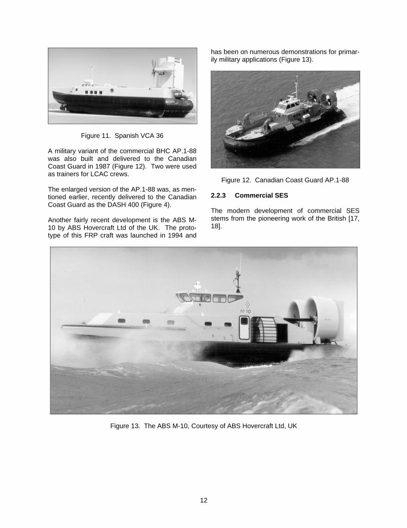
one was the subject of trials by the British Royal Navy, primarily in a mine countermeasures role. Six were purchased by Iran. The Vosper Thornycroft 105-ton VT-2, converted to an amphibious ACV in 1975 from the marine-screw propelled VT-1, was a prototype which was also extensively evaluated by the Royal Navy but was subsequently scrapped. One of the four commercial 200-ton SR.N4 MK2’s car ferries was also temporarily converted and tested by the Royal Navy for an MCM application. The West German Navy also explored MCM applications for the SR.N4 MK2s. The former Soviet Union has, since 1965, pro-duced more military ACVs than any other country. Table 1 lists 13 of their most prominent craft, most of which have been put into quantity production. Their largest craft is the 380-ton Pomornik which was launched in 1985 and is shown in Figure 10. The Spanish VCA-36 was launched in 1986 to improve the rapid-lift capability of the Spanish armed forces. This ACV will carry a 14-ton pay-load 189 nm at a cruise speed of 50 knots. Bow and stern ramps on the VCA-36 provide access to the vehicle deck, which can also be reached from the side cabins. Maneuvering control is assisted with the unique application of vectored engine exhaust at the stern (Figure 11). South Korea has developed several small am-phibious-assault ACVs of about 50 tons.
Figure 10. The Former USSR Pomornik Military ACV
12
Figure 11. Spanish VCA 36
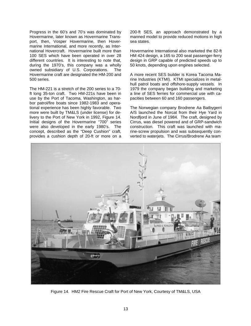
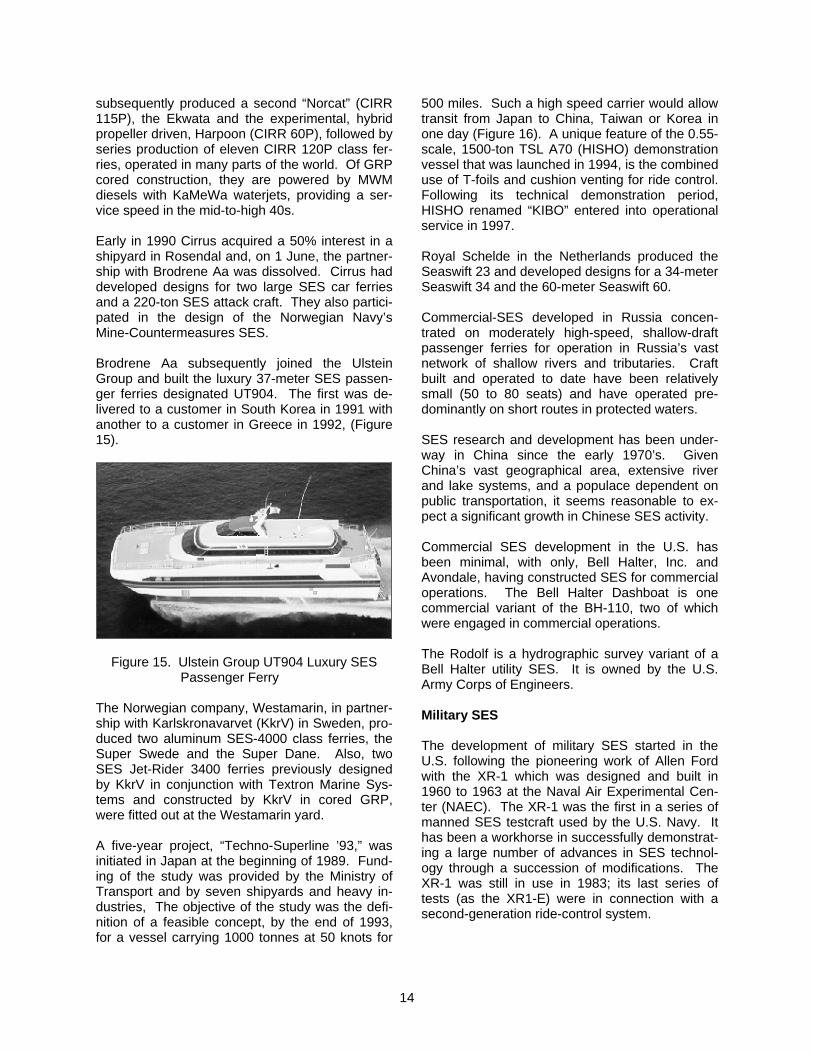
A military variant of the commercial BHC AP.1-88 was also built and delivered to the Canadian Coast Guard in 1987 (Figure 12). Two were used as trainers for LCAC crews. The enlarged version of the AP.1-88 was, as men-tioned earlier, recently delivered to the Canadian Coast Guard as the DASH 400 (Figure 4). Another fairly recent development is the ABS M-10 by ABS Hovercraft Ltd of the UK. The proto-type of this FRP craft was launched in 1994 and
has been on numerous demonstrations for primar-ily military applications (Figure 13).
Figure 12. Canadian Coast Guard AP.1-88 2.2.3 Commercial SES The modern development of commercial SES stems from the pioneering work of the British [17, 18].
Figure 13. The ABS M-10, Courtesy of ABS Hovercraft Ltd, UK
13
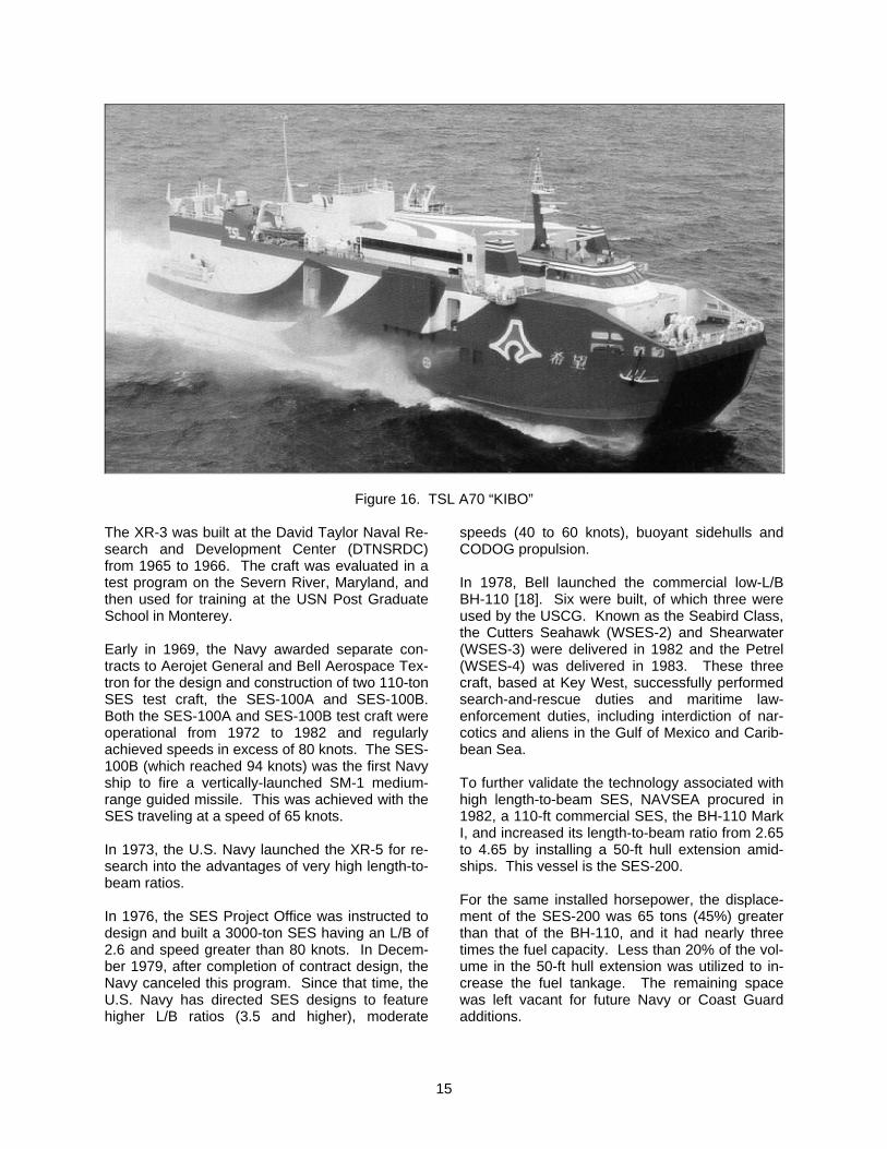
Progress in the 60’s and 70’s was dominated by Hovermarine, later known as Hovermarine Trans-port, then, Vosper Hovermarine, then Hover-marine International, and more recently, as Inter-national Hovercraft. Hovermarine built more than 100 SES which have been operated in over 28 different countries. It is interesting to note that, during the 1970’s, this company was a wholly owned subsidiary of U.S. Corporations. The Hovermarine craft are designated the HM-200 and 500 series. The HM-221 is a stretch of the 200 series to a 70-ft long 35-ton craft. Two HM-221s have been in use by the Port of Tacoma, Washington, as har-bor patrol/fire boats since 1982-1983 and opera-tional experience has been highly favorable. Two more were built by TM&LS (under license) for de-livery to the Port of New York in 1992, Figure 14. Initial designs of the Hovermarine “700” series were also developed in the early 1980’s. The concept, described as the “Deep Cushion” craft, provides a cushion depth of 20-ft or more on a
200-ft SES, an approach demonstrated by a manned model to provide reduced motions in high sea states. Hovermarine International also marketed the 82-ft HM 424 design, a 165 to 200 seat passenger-ferry design in GRP capable of predicted speeds up to 50 knots, depending upon engines selected. A more recent SES builder is Korea Tacoma Ma-rine Industries (KTMI). KTMI specializes in metal-hull patrol boats and offshore-supply vessels. In 1979 the company began building and marketing a line of SES ferries for commercial use with ca-pacities between 60 and 160 passengers. The Norwegian company Brodrene Aa Batbygerri A/S launched the Norcat from their Hye Yard in Nordfjord in June of 1984. The craft, designed by Cirrus, was diesel powered and of GRP-sandwich construction. This craft was launched with ma-rine-screw propulsion and was subsequently con-verted to waterjets. The Cirrus/Brodrene Aa team
Figure 14. HM2 Fire Rescue Craft for Port of New York, Courtesy of TM&LS, USA
14
subsequently produced a second “Norcat” (CIRR 115P), the Ekwata and the experimental, hybrid propeller driven, Harpoon (CIRR 60P), followed by series production of eleven CIRR 120P class fer-ries, operated in many parts of the world. Of GRP cored construction, they are powered by MWM diesels with KaMeWa waterjets, providing a ser-vice speed in the mid-to-high 40s. Early in 1990 Cirrus acquired a 50% interest in a shipyard in Rosendal and, on 1 June, the partner-ship with Brodrene Aa was dissolved. Cirrus had developed designs for two large SES car ferries and a 220-ton SES attack craft. They also partici-pated in the design of the Norwegian Navy’s Mine-Countermeasures SES. Brodrene Aa subsequently joined the Ulstein Group and built the luxury 37-meter SES passen-ger ferries designated UT904. The first was de-livered to a customer in South Korea in 1991 with another to a customer in Greece in 1992, (Figure 15).
Figure 15. Ulstein Group UT904 Luxury SES Passenger Ferry
The Norwegian company, Westamarin, in partner-ship with Karlskronavarvet (KkrV) in Sweden, pro-duced two aluminum SES-4000 class ferries, the Super Swede and the Super Dane. Also, two SES Jet-Rider 3400 ferries previously designed by KkrV in conjunction with Textron Marine Sys-tems and constructed by KkrV in cored GRP, were fitted out at the Westamarin yard. A five-year project, “Techno-Superline ’93,” was initiated in Japan at the beginning of 1989. Fund-ing of the study was provided by the Ministry of Transport and by seven shipyards and heavy in-dustries, The objective of the study was the defi-nition of a feasible concept, by the end of 1993, for a vessel carrying 1000 tonnes at 50 knots for
500 miles. Such a high speed carrier would allow transit from Japan to China, Taiwan or Korea in one day (Figure 16). A unique feature of the 0.55-scale, 1500-ton TSL A70 (HISHO) demonstration vessel that was launched in 1994, is the combined use of T-foils and cushion venting for ride control. Following its technical demonstration period, HISHO renamed “KIBO” entered into operational service in 1997. Royal Schelde in the Netherlands produced the Seaswift 23 and developed designs for a 34-meter Seaswift 34 and the 60-meter Seaswift 60. Commercial-SES developed in Russia concen-trated on moderately high-speed, shallow-draft passenger ferries for operation in Russia’s vast network of shallow rivers and tributaries. Craft built and operated to date have been relatively small (50 to 80 seats) and have operated pre-dominantly on short routes in protected waters. SES research and development has been under-way in China since the early 1970’s. Given China’s vast geographical area, extensive river and lake systems, and a populace dependent on public transportation, it seems reasonable to ex-pect a significant growth in Chinese SES activity. Commercial SES development in the U.S. has been minimal, with only, Bell Halter, Inc. and Avondale, having constructed SES for commercial operations. The Bell Halter Dashboat is one commercial variant of the BH-110, two of which were engaged in commercial operations. The Rodolf is a hydrographic survey variant of a Bell Halter utility SES. It is owned by the U.S. Army Corps of Engineers. Military SES The development of military SES started in the U.S. following the pioneering work of Allen Ford with the XR-1 which was designed and built in 1960 to 1963 at the Naval Air Experimental Cen-ter (NAEC). The XR-1 was the first in a series of manned SES testcraft used by the U.S. Navy. It has been a workhorse in successfully demonstrat-ing a large number of advances in SES technol-ogy through a succession of modifications. The XR-1 was still in use in 1983; its last series of tests (as the XR1-E) were in connection with a second-generation ride-control system.
15
Figure 16. TSL A70 “KIBO”
The XR-3 was built at the David Taylor Naval Re-search and Development Center (DTNSRDC) from 1965 to 1966. The craft was evaluated in a test program on the Severn River, Maryland, and then used for training at the USN Post Graduate School in Monterey. Early in 1969, the Navy awarded separate con-tracts to Aerojet General and Bell Aerospace Tex-tron for the design and construction of two 110-ton SES test craft, the SES-100A and SES-100B. Both the SES-100A and SES-100B test craft were operational from 1972 to 1982 and regularly achieved speeds in excess of 80 knots. The SES-100B (which reached 94 knots) was the first Navy ship to fire a vertically-launched SM-1 medium-range guided missile. This was achieved with the SES traveling at a speed of 65 knots. In 1973, the U.S. Navy launched the XR-5 for re-search into the advantages of very high length-to-beam ratios. In 1976, the SES Project Office was instructed to design and built a 3000-ton SES having an L/B of 2.6 and speed greater than 80 knots. In Decem-ber 1979, after completion of contract design, the Navy canceled this program. Since that time, the U.S. Navy has directed SES designs to feature higher L/B ratios (3.5 and higher), moderate
speeds (40 to 60 knots), buoyant sidehulls and CODOG propulsion. In 1978, Bell launched the commercial low-L/B BH-110 [18]. Six were built, of which three were used by the USCG. Known as the Seabird Class, the Cutters Seahawk (WSES-2) and Shearwater (WSES-3) were delivered in 1982 and the Petrel (WSES-4) was delivered in 1983. These three craft, based at Key West, successfully performed search-and-rescue duties and maritime law-enforcement duties, including interdiction of nar-cotics and aliens in the Gulf of Mexico and Carib-bean Sea. To further validate the technology associated with high length-to-beam SES, NAVSEA procured in 1982, a 110-ft commercial SES, the BH-110 Mark I, and increased its length-to-beam ratio from 2.65 to 4.65 by installing a 50-ft hull extension amid-ships. This vessel is the SES-200. For the same installed horsepower, the displace-ment of the SES-200 was 65 tons (45%) greater than that of the BH-110, and it had nearly three times the fuel capacity. Less than 20% of the vol-ume in the 50-ft hull extension was utilized to in-crease the fuel tankage. The remaining space was left vacant for future Navy or Coast Guard additions.
16
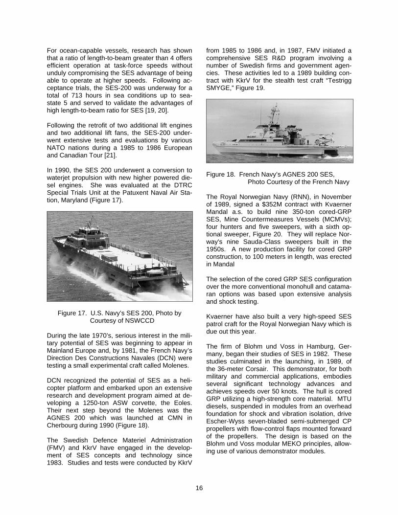
For ocean-capable vessels, research has shown that a ratio of length-to-beam greater than 4 offers efficient operation at task-force speeds without unduly compromising the SES advantage of being able to operate at higher speeds. Following ac-ceptance trials, the SES-200 was underway for a total of 713 hours in sea conditions up to sea-state 5 and served to validate the advantages of high length-to-beam ratio for SES [19, 20]. Following the retrofit of two additional lift engines and two additional lift fans, the SES-200 under-went extensive tests and evaluations by various NATO nations during a 1985 to 1986 European and Canadian Tour [21]. In 1990, the SES 200 underwent a conversion to waterjet propulsion with new higher powered die-sel engines. She was evaluated at the DTRC Special Trials Unit at the Patuxent Naval Air Sta-tion, Maryland (Figure 17).
Figure 17. U.S. Navy’s SES 200, Photo by Courtesy of NSWCCD
During the late 1970’s, serious interest in the mili-tary potential of SES was beginning to appear in Mainland Europe and, by 1981, the French Navy’s Direction Des Constructions Navales (DCN) were testing a small experimental craft called Molenes. DCN recognized the potential of SES as a heli-copter platform and embarked upon an extensive research and development program aimed at de-veloping a 1250-ton ASW corvette, the Eoles. Their next step beyond the Molenes was the AGNES 200 which was launched at CMN in Cherbourg during 1990 (Figure 18). The Swedish Defence Materiel Administration (FMV) and KkrV have engaged in the develop-ment of SES concepts and technology since 1983. Studies and tests were conducted by KkrV
from 1985 to 1986 and, in 1987, FMV initiated a comprehensive SES R&D program involving a number of Swedish firms and government agen-cies. These activities led to a 1989 building con-tract with KkrV for the stealth test craft “Testrigg SMYGE,” Figure 19.
Figure 18. French Navy’s AGNES 200 SES,
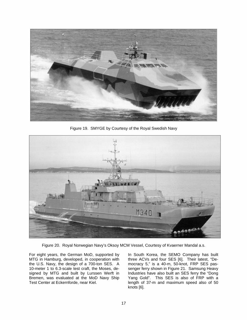
Photo Courtesy of the French Navy The Royal Norwegian Navy (RNN), in November of 1989, signed a $352M contract with Kvaerner Mandal a.s. to build nine 350-ton cored-GRP SES, Mine Countermeasures Vessels (MCMVs); four hunters and five sweepers, with a sixth op-tional sweeper, Figure 20. They will replace Nor-way's nine Sauda-Class sweepers built in the 1950s. A new production facility for cored GRP construction, to 100 meters in length, was erected in Mandal The selection of the cored GRP SES configuration over the more conventional monohull and catama-ran options was based upon extensive analysis and shock testing. Kvaerner have also built a very high-speed SES patrol craft for the Royal Norwegian Navy which is due out this year. The firm of Blohm und Voss in Hamburg, Ger-many, began their studies of SES in 1982. These studies culminated in the launching, in 1989, of the 36-meter Corsair. This demonstrator, for both military and commercial applications, embodies several significant technology advances and achieves speeds over 50 knots. The hull is cored GRP utilizing a high-strength core material. MTU diesels, suspended in modules from an overhead foundation for shock and vibration isolation, drive Escher-Wyss seven-bladed semi-submerged CP propellers with flow-control flaps mounted forward of the propellers. The design is based on the Blohm und Voss modular MEKO principles, allow-ing use of various demonstrator modules.
17
Figure 19. SMYGE by Courtesy of the Royal Swedish Navy
Figure 20. Royal Norwegian Navy’s Oksoy MCM Vessel, Courtesy of Kvaerner Mandal a.s.
For eight years, the German MoD, supported by MTG in Hamburg, developed, in cooperation with the U.S. Navy, the design of a 700-ton SES. A 10-meter 1 to 6.3-scale test craft, the Moses, de-signed by MTG and built by Lurssen Werft in Bremen, was evaluated at the MoD Navy Ship Test Center at Eckernforde, near Kiel.
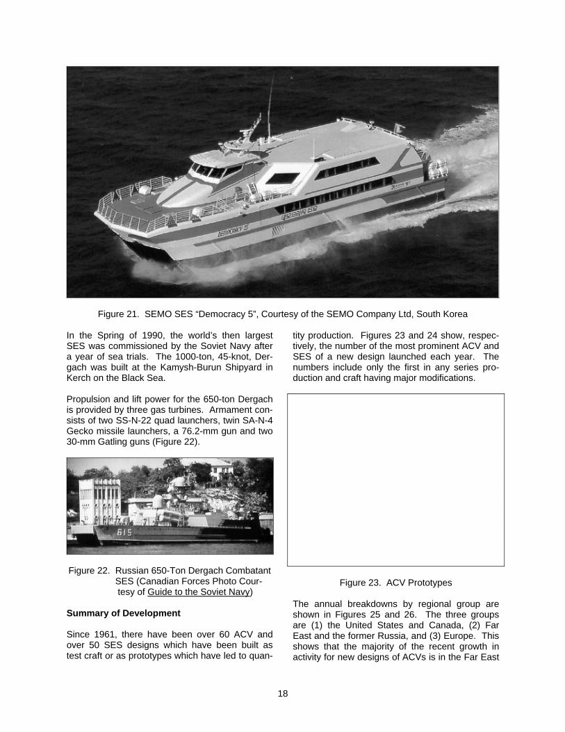
In South Korea, the SEMO Company has built three ACVs and four SES [6]. Their latest, “De-mocracy 5,” is a 40-m, 50-knot, FRP SES pas-senger ferry shown in Figure 21. Samsung Heavy Industries have also built an SES ferry the “Dong Yang Gold”. This SES is also of FRP with a length of 37-m and maximum speed also of 50 knots [6].
18
Figure 21. SEMO SES “Democracy 5”, Courtesy of the SEMO Company Ltd, South Korea
In the Spring of 1990, the world’s then largest SES was commissioned by the Soviet Navy after a year of sea trials. The 1000-ton, 45-knot, Der-gach was built at the Kamysh-Burun Shipyard in Kerch on the Black Sea. Propulsion and lift power for the 650-ton Dergach is provided by three gas turbines. Armament con-sists of two SS-N-22 quad launchers, twin SA-N-4 Gecko missile launchers, a 76.2-mm gun and two 30-mm Gatling guns (Figure 22).
Figure 22. Russian 650-Ton Dergach Combatant SES (Canadian Forces Photo Cour- tesy of Guide to the Soviet Navy)
Summary of Development Since 1961, there have been over 60 ACV and over 50 SES designs which have been built as test craft or as prototypes which have led to quan-
tity production. Figures 23 and 24 show, respec-tively, the number of the most prominent ACV and SES of a new design launched each year. The numbers include only the first in any series pro-duction and craft having major modifications.
Figure 23. ACV Prototypes The annual breakdowns by regional group are shown in Figures 25 and 26. The three groups are (1) the United States and Canada, (2) Far East and the former Russia, and (3) Europe. This shows that the majority of the recent growth in activity for new designs of ACVs is in the Far East
19
and the former USSR. For SES, the largest re-cent growth has been in Europe. In the U.S., only six new designs (ACVs or SES) of a significant size have been built since 1980.
Figure 24. SES Prototypes
Figure 25. ACV Prototypes by Region The growth in the world’s market for fast ferries is illustrated in Figure 27. This growth has been met by hydrofoil craft, catamarans, monohulls, SES and ACVs. The competition is fierce and ACVs and SES can only be justified on routes where high speeds, generally over 40 knots, are of interest.
Figure 26. SES Prototypes by Region
Figure 27. The Fast-Ferry Market (1996) 3.0 TECHNOLOGY DEVELOPMENT In the last 25 years, significant advances have been made toward developing a well-established discipline of hovercraft design practice, approach-ing that which is available for conventional ships. This has come about as a result of the wealth of experience gained by comparing and validating design procedures and design criteria against the very large database of full-scale and model-scale information which has accumulated over a period of more than 30 years. Foremost in this experience in the U.S. has been that provided by the U.S. Navy/Marine Corps Am-phibious Assault Landing Craft Program, which produced the AALC JEFF(A) and JEFF(B) proto-types, and by the Amphibious Warfare and Stra-tegic Sealift Program which produced the Landing
20
Craft Air Cushion (LCAC), which has been in quantity production since 1984 [22]. Close to this in significance was the U.S. Navy’s 3KSES program which during the period of 1969 to 1980 expended over $400M on SES develop-ment. This section of the paper provides an overview of the experience as it relates to some of the more important technology developments which have influenced craft design. Unlike the hull of a conventional ship, the hard structure of an ACV or the wet-deck of an SES, under normal operating conditions, is seldom in contact with the water. The study of craft resis-tance, stability and seakeeping normally associ-ated with the hullform design of a conventional ship is, therefore, for an ACV or SES, associated strongly with the study of ACV skirts or SES seal systems. 3.1 Performance ACVs and SES can be designed for very high speeds. In calm conditions, the speed of an ACV or SES can generally be much higher than for other forms of marine transport having the same installed power. Usually, the thrust and installed propulsion power are determined by one or more of the following requirements: • To climb an overland slope of a specific gra-
dient (ACV only), • To traverse the hump in the overwater drag
curve with a specified forward acceleration (ACV and SES), and
• To cruise at a particular speed, above hump
speed, in a specified sea state (ACV and SES).
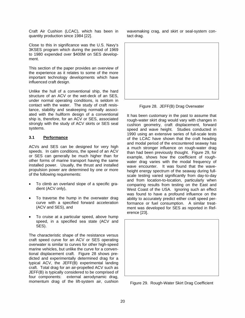
The characteristic shape of the resistance versus craft speed curve for an ACV or SES operating overwater is similar to curves for other high-speed marine vehicles, but unlike the curve for a conven-tional displacement craft. Figure 28 shows pre-dicted and experimentally determined drag for a typical ACV, the JEFF(B) experimental landing craft. Total drag for an air-propelled ACV such as JEFF(B) is typically considered to be comprised of four components: external aerodynamic drag, momentum drag of the lift-system air, cushion
wavemaking crag, and skirt or seal-system con-tact drag.
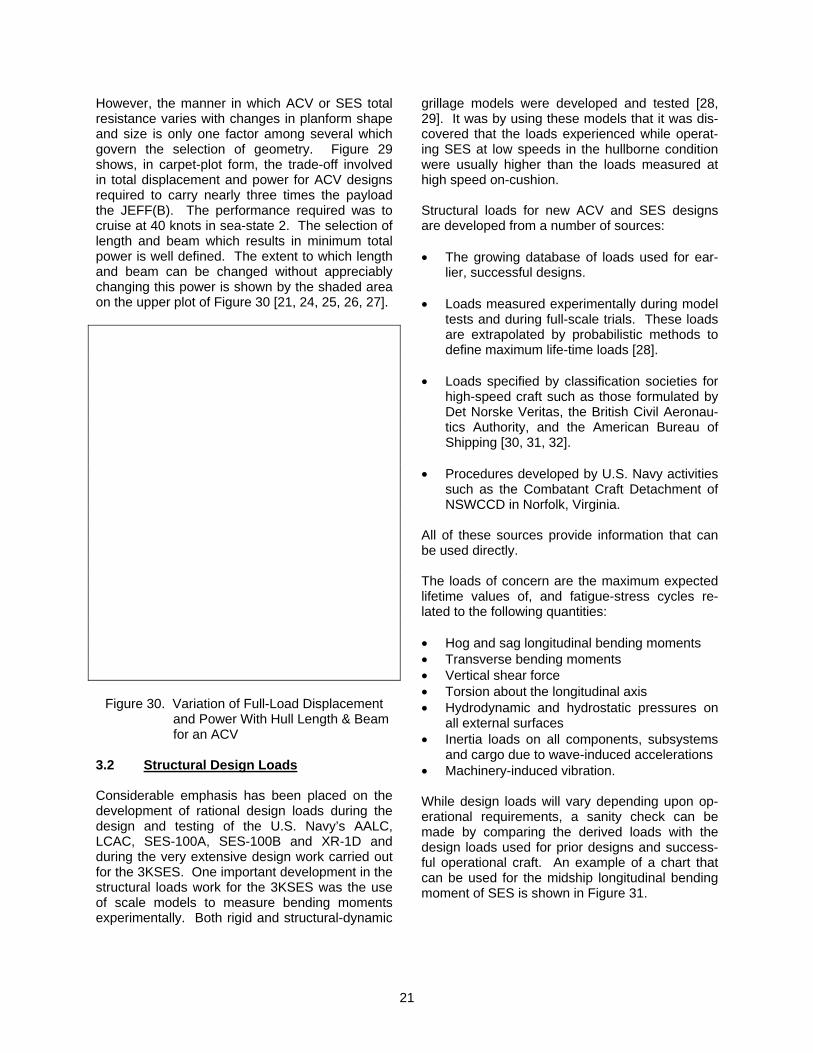
Figure 28. JEFF(B) Drag Overwater It has been customary in the past to assume that rough-water skirt drag would vary with changes in cushion geometry, craft displacement, forward speed and wave height. Studies conducted in 1990 using an extensive series of full-scale tests of the LCAC have shown that the craft heading and modal period of the encountered seaway has a much stronger influence on rough-water drag than had been previously thought. Figure 29, for example, shows how the coefficient of rough-water drag varies with the modal frequency of wave encounter. It was found that the wave-height energy spectrum of the seaway during full-scale testing varied significantly from day-to-day and from location-to-location, particularly when comparing results from testing on the East and West Coast of the USA. Ignoring such an effect was found to have a profound influence on the ability to accurately predict either craft speed per-formance or fuel consumption. A similar treat-ment was developed for SES as reported in Ref-erence [23].
Figure 29. Rough-Water Skirt Drag Coefficient
21
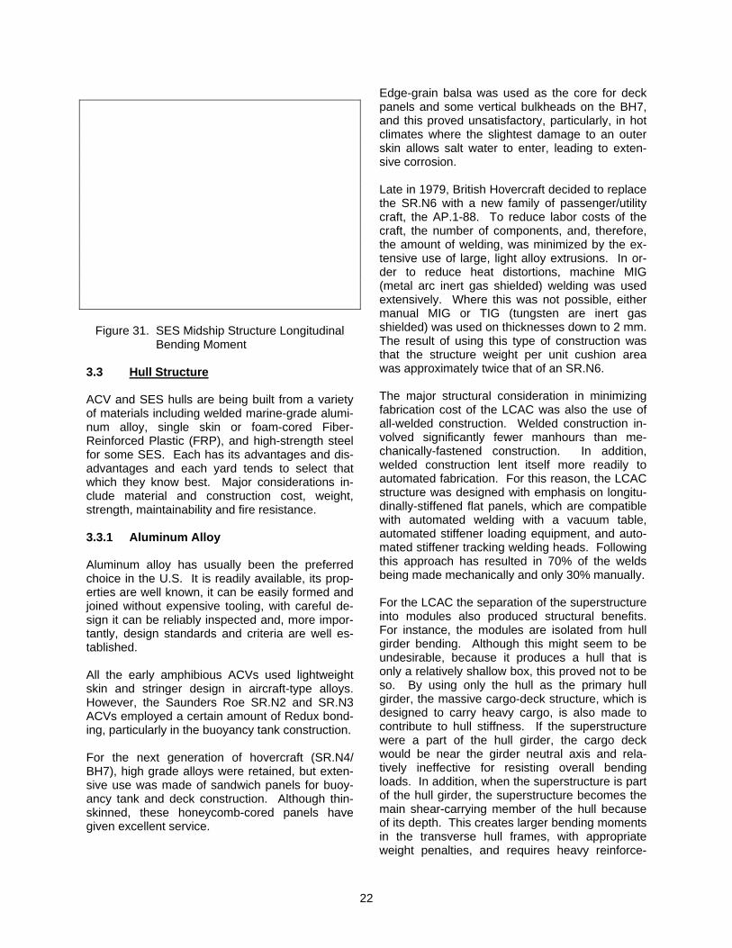
However, the manner in which ACV or SES total resistance varies with changes in planform shape and size is only one factor among several which govern the selection of geometry. Figure 29 shows, in carpet-plot form, the trade-off involved in total displacement and power for ACV designs required to carry nearly three times the payload the JEFF(B). The performance required was to cruise at 40 knots in sea-state 2. The selection of length and beam which results in minimum total power is well defined. The extent to which length and beam can be changed without appreciably changing this power is shown by the shaded area on the upper plot of Figure 30 [21, 24, 25, 26, 27].
Figure 30. Variation of Full-Load Displacement and Power With Hull Length & Beam for an ACV
3.2 Structural Design Loads Considerable emphasis has been placed on the development of rational design loads during the design and testing of the U.S. Navy’s AALC, LCAC, SES-100A, SES-100B and XR-1D and during the very extensive design work carried out for the 3KSES. One important development in the structural loads work for the 3KSES was the use of scale models to measure bending moments experimentally. Both rigid and structural-dynamic
grillage models were developed and tested [28, 29]. It was by using these models that it was dis-covered that the loads experienced while operat-ing SES at low speeds in the hullborne condition were usually higher than the loads measured at high speed on-cushion. Structural loads for new ACV and SES designs are developed from a number of sources: • The growing database of loads used for ear-
lier, successful designs. • Loads measured experimentally during model
tests and during full-scale trials. These loads are extrapolated by probabilistic methods to define maximum life-time loads [28].
• Loads specified by classification societies for
high-speed craft such as those formulated by Det Norske Veritas, the British Civil Aeronau-tics Authority, and the American Bureau of Shipping [30, 31, 32].
• Procedures developed by U.S. Navy activities
such as the Combatant Craft Detachment of NSWCCD in Norfolk, Virginia.
All of these sources provide information that can be used directly. The loads of concern are the maximum expected lifetime values of, and fatigue-stress cycles re-lated to the following quantities: • Hog and sag longitudinal bending moments • Transverse bending moments • Vertical shear force • Torsion about the longitudinal axis • Hydrodynamic and hydrostatic pressures on
all external surfaces • Inertia loads on all components, subsystems
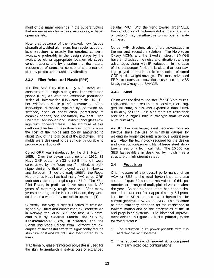
and cargo due to wave-induced accelerations • Machinery-induced vibration. While design loads will vary depending upon op-erational requirements, a sanity check can be made by comparing the derived loads with the design loads used for prior designs and success-ful operational craft. An example of a chart that can be used for the midship longitudinal bending moment of SES is shown in Figure 31.
22
Figure 31. SES Midship Structure Longitudinal Bending Moment
3.3 Hull Structure ACV and SES hulls are being built from a variety of materials including welded marine-grade alumi-num alloy, single skin or foam-cored Fiber-Reinforced Plastic (FRP), and high-strength steel for some SES. Each has its advantages and dis-advantages and each yard tends to select that which they know best. Major considerations in-clude material and construction cost, weight, strength, maintainability and fire resistance. 3.3.1 Aluminum Alloy Aluminum alloy has usually been the preferred choice in the U.S. It is readily available, its prop-erties are well known, it can be easily formed and joined without expensive tooling, with careful de-sign it can be reliably inspected and, more impor-tantly, design standards and criteria are well es-tablished. All the early amphibious ACVs used lightweight skin and stringer design in aircraft-type alloys. However, the Saunders Roe SR.N2 and SR.N3 ACVs employed a certain amount of Redux bond-ing, particularly in the buoyancy tank construction. For the next generation of hovercraft (SR.N4/ BH7), high grade alloys were retained, but exten-sive use was made of sandwich panels for buoy-ancy tank and deck construction. Although thin-skinned, these honeycomb-cored panels have given excellent service.
Edge-grain balsa was used as the core for deck panels and some vertical bulkheads on the BH7, and this proved unsatisfactory, particularly, in hot climates where the slightest damage to an outer skin allows salt water to enter, leading to exten-sive corrosion. Late in 1979, British Hovercraft decided to replace the SR.N6 with a new family of passenger/utility craft, the AP.1-88. To reduce labor costs of the craft, the number of components, and, therefore, the amount of welding, was minimized by the ex-tensive use of large, light alloy extrusions. In or-der to reduce heat distortions, machine MIG (metal arc inert gas shielded) welding was used extensively. Where this was not possible, either manual MIG or TIG (tungsten are inert gas shielded) was used on thicknesses down to 2 mm. The result of using this type of construction was that the structure weight per unit cushion area was approximately twice that of an SR.N6. The major structural consideration in minimizing fabrication cost of the LCAC was also the use of all-welded construction. Welded construction in-volved significantly fewer manhours than me-chanically-fastened construction. In addition, welded construction lent itself more readily to automated fabrication. For this reason, the LCAC structure was designed with emphasis on longitu-dinally-stiffened flat panels, which are compatible with automated welding with a vacuum table, automated stiffener loading equipment, and auto-mated stiffener tracking welding heads. Following this approach has resulted in 70% of the welds being made mechanically and only 30% manually. For the LCAC the separation of the superstructure into modules also produced structural benefits. For instance, the modules are isolated from hull girder bending. Although this might seem to be undesirable, because it produces a hull that is only a relatively shallow box, this proved not to be so. By using only the hull as the primary hull girder, the massive cargo-deck structure, which is designed to carry heavy cargo, is also made to contribute to hull stiffness. If the superstructure were a part of the hull girder, the cargo deck would be near the girder neutral axis and rela-tively ineffective for resisting overall bending loads. In addition, when the superstructure is part of the hull girder, the superstructure becomes the main shear-carrying member of the hull because of its depth. This creates larger bending moments in the transverse hull frames, with appropriate weight penalties, and requires heavy reinforce-
23
ment of the many openings in the superstructure that are necessary for access, air intakes, exhaust openings, etc. Note that because of the relatively low fatigue strength of welded aluminum, high-cycle fatigue of local structure is usually the greatest concern, avoidable preferably in the design stage by the avoidance of, or appropriate location of, stress concentrations, and by ensuring that the natural frequencies of structural components are not ex-cited by predictable machinery vibrations. 3.3.2 Fiber-Reinforced Plastic (FRP) The first SES ferry (the Denny D-2, 1962) was constructed of single-skin glass fiber-reinforced plastic (FRP) as were the extensive production series of Hovermarine (HM) craft in the UK. Fi-ber-Reinforced-Plastic (FRP) construction offers lightweight, durability, repairability, corrosion re-sistance, ease of construction (particularly of complex shapes) and reasonably low cost. The HM craft used woven and unidirectional glass rov-ings with polyester resin. The structure of this craft could be built in less than four months while the cost of the molds and tooling amounted to about 15% of the total cost of the prototype. The molds were designed to be sufficiently durable to produce over 100 craft. Cored GRP was introduced by the U.S. Navy in 1955. Over the seven years up until 1962, 32 Navy GRP boats from 33 to 50 ft in length were constructed by the “core mold” method, a tech-nique similar to that employed today in Norway and Sweden. Since the early 1960’s, the Royal Netherlands Navy has had many PVC-cored GRP craft constructed in lengths up to 77 ft. The 77-ft Pilot Boats, in particular, have seen nearly 30 years of extremely rough service. After many years operating off the Hook of Holland, they were sold to India where they are still in operation [1]. Currently, the very successful series of craft de-signed by Cirrus and constructed by Brodrene Aa in Norway, the MCM SES and fast SES patrol craft built by Kvaerner Mandal, the SES by Karlskronavarvet (KkrV) in Sweden, and the Blohm und Voss Corsair from Germany are ex-amples of successful efforts to significantly reduce structural cost and weight using foam-cored struc-tures. Traditionally, glass-reinforced polyester is used for the skin, to sandwich a laid-up core of expanded
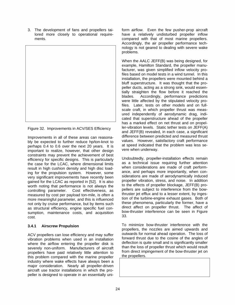
cellular PVC. With the trend toward larger SES, the introduction of higher-modulus fibers (aramids or carbon) may be attractive to improve laminate stiffness. Cored FRP structure also offers advantages in thermal and acoustic insulation. The Norwegian Oksoy MCMs and the Swedish stealth SMYGE have emphasized the noise and vibration damping advantages along with IR reduction. In the case of the passenger ferries it is clear that cost sav-ings played as much a role in selection of cored GRP as did weight savings. The most advanced FRP structures are now those used on the ABS M-10, the Oksoy and SMYGE. 3.3.3 Steel China was the first to use steel for SES structures. High-tensile steel results in a heavier, more rug-ged structure, but is less expensive than alumi-num alloy or FRP. It is also more fire resistance and has a higher fatigue strength than welded aluminum alloy. As SES become larger, steel becomes more at-tractive since the use of minimum gauges for welding no longer presents a serious weight pen-alty. Also, the technology required for the design and construction/producibility of large steel struc-ture is less of a technical risk. The 20,000 ton SES fast-sealift ship designed by Ingalls has a structure of high-strength steel. 3.4 Propulsion One measure of the overall performance of an ACV or SES is the total hp/ton-knot at cruise speed. Figure 32 summarizes values of this pa-rameter for a range of craft, plotted versus calen-dar year. As can be seen, there has been a dra-matic improvement from approximately 5 hp/ton-knot for the SR.N1 to less than 1 hp/ton-knot for current generation ACVs and SES. This measure of craft efficiency depends on the resistance to forward motion and on the efficiencies of the lift and propulsion systems. The historical improve-ment evident in Figure 32 is due primarily to the following factors: 1. The reduction in lift power possible with cur-
rent flexible skirt systems. 2. The reduced drag of fingered skirts compared
with early jetted-bag configurations.
24
3. The development of fans and propellers tai-lored more closely to operational require-ments.
Figure 32. Improvements in ACV/SES Efficiency Improvements in all of these areas can reasona-bly be expected to further reduce hp/ton-knot to perhaps 0.4 to 0.6 over the next 20 years. It is important to realize, however, that other design constraints may prevent the achievement of best efficiency for specific designs. This is particularly the case for the LCAC, where dimensional limits result in high cushion density and high disc load-ing for the propulsion system. However, some very significant improvements have recently been gained for the LCAC as reported in [52]. It is also worth noting that performance is not always the controlling parameter. Cost effectiveness, as measured by cost per payload ton-mile, is often a more meaningful parameter, and this is influenced not only by cruise performance, but by items such as structural efficiency, engine specific fuel con-sumption, maintenance costs, and acquisition cost. 3.4.1 Airscrew Propulsion ACV propellers can lose efficiency and may suffer vibration problems when used in an installation where the airflow entering the propeller disk is severely non-uniform. Manufacturers of aircraft propellers have paid relatively little attention to this problem compared with the marine propeller industry where wake effects have always been a major consideration. Nearly all propeller-driven aircraft use tractor installations in which the pro-peller is designed to operate in an essentially uni-
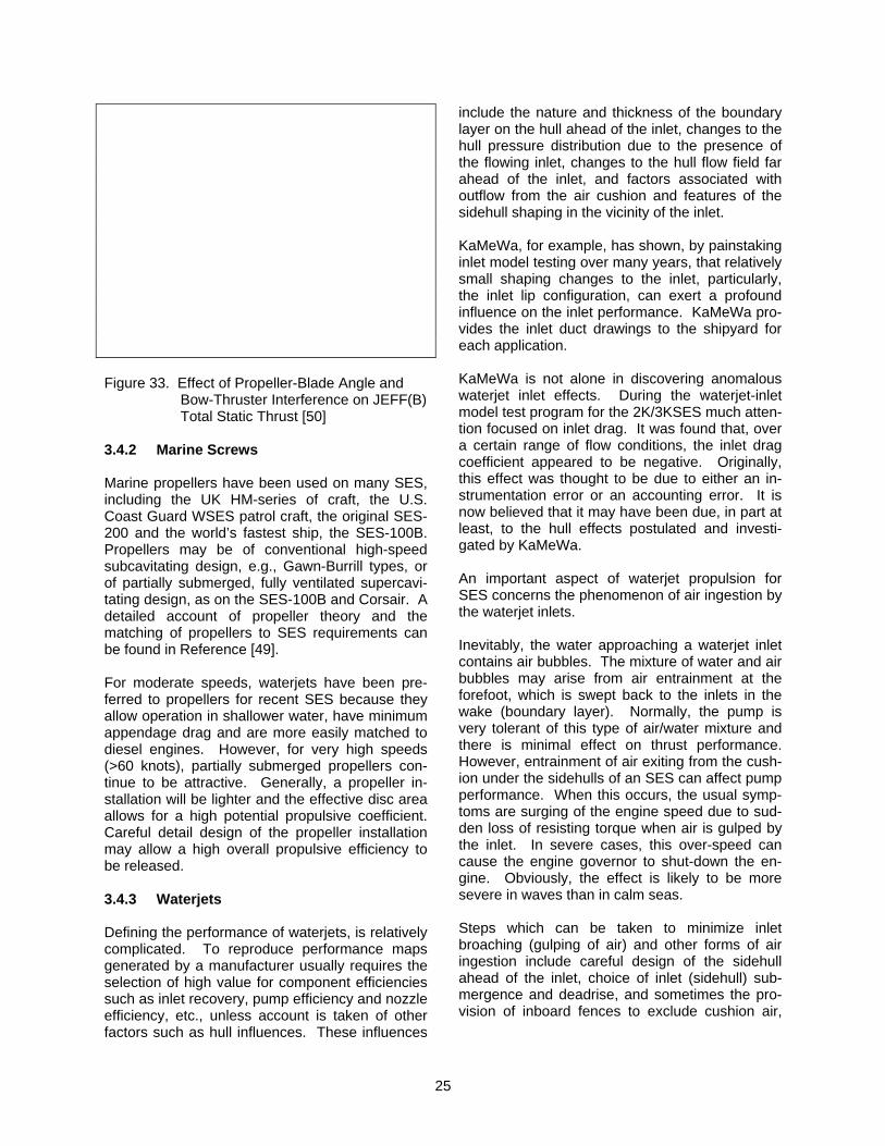
form airflow. Even the few pusher-prop aircraft have a relatively undisturbed propeller inflow compared with that of most marine propellers. Accordingly, the air propeller performance tech-nology is not geared to dealing with severe wake problems. When the AALC JEFF(B) was being designed, for example, Hamilton Standard, the propeller manu-facturer, was given simplified inflow velocity pro-files based on model tests in a wind tunnel. In this installation, the propellers were mounted behind a bluff superstructure. It was thought that the pro-peller ducts, acting as a strong sink, would essen-tially straighten the flow before it reached the blades. Accordingly, performance predictions were little affected by the stipulated velocity pro-files. Later, tests on other models and on full-scale craft, in which propeller thrust was meas-ured independently of aerodynamic drag, indi-cated that superstructure ahead of the propeller has a marked effect on net thrust and on propel-ler-vibration levels. Static tether tests on JEFF(A) and JEFF(B) revealed, in each case, a significant difference between predicted and measured thrust values. However, satisfactory craft performance at speed indicated that the problem was less se-vere when underway. Undoubtedly, propeller-installation effects remain as a technical issue requiring further attention when considerations are made of craft perform-ance, and perhaps more importantly, when con-siderations are made of aerodynamically induced propeller vibration, stress, and noise. In addition to the effects of propeller blockage, JEFF(B) pro-pellers are subject to interference from the bow-thruster jet efflux and to a lesser extent, by inges-tion of the turbine-engine exhaust gases. Both of these phenomena, particularly the former, have a direct affect on propeller thrust. The affect of bow-thruster interference can be seen in Figure 33. To minimize bow-thruster interference with the propellers, the nozzles are aimed upwards and outwards for normal ahead operation. The loss of forward thrust due to the cosine of the angles of deflection is quite small and is significantly smaller than the loss of propeller thrust which would result from direct impingement of the bow-thruster jet on the propellers.
25
Figure 33. Effect of Propeller-Blade Angle and
Bow-Thruster Interference on JEFF(B) Total Static Thrust [50]
3.4.2 Marine Screws Marine propellers have been used on many SES, including the UK HM-series of craft, the U.S. Coast Guard WSES patrol craft, the original SES-200 and the world’s fastest ship, the SES-100B. Propellers may be of conventional high-speed subcavitating design, e.g., Gawn-Burrill types, or of partially submerged, fully ventilated supercavi-tating design, as on the SES-100B and Corsair. A detailed account of propeller theory and the matching of propellers to SES requirements can be found in Reference [49]. For moderate speeds, waterjets have been pre-ferred to propellers for recent SES because they allow operation in shallower water, have minimum appendage drag and are more easily matched to diesel engines. However, for very high speeds (>60 knots), partially submerged propellers con-tinue to be attractive. Generally, a propeller in-stallation will be lighter and the effective disc area allows for a high potential propulsive coefficient. Careful detail design of the propeller installation may allow a high overall propulsive efficiency to be released. 3.4.3 Waterjets Defining the performance of waterjets, is relatively complicated. To reproduce performance maps generated by a manufacturer usually requires the selection of high value for component efficiencies such as inlet recovery, pump efficiency and nozzle efficiency, etc., unless account is taken of other factors such as hull influences. These influences
include the nature and thickness of the boundary layer on the hull ahead of the inlet, changes to the hull pressure distribution due to the presence of the flowing inlet, changes to the hull flow field far ahead of the inlet, and factors associated with outflow from the air cushion and features of the sidehull shaping in the vicinity of the inlet. KaMeWa, for example, has shown, by painstaking inlet model testing over many years, that relatively small shaping changes to the inlet, particularly, the inlet lip configuration, can exert a profound influence on the inlet performance. KaMeWa pro-vides the inlet duct drawings to the shipyard for each application. KaMeWa is not alone in discovering anomalous waterjet inlet effects. During the waterjet-inlet model test program for the 2K/3KSES much atten-tion focused on inlet drag. It was found that, over a certain range of flow conditions, the inlet drag coefficient appeared to be negative. Originally, this effect was thought to be due to either an in-strumentation error or an accounting error. It is now believed that it may have been due, in part at least, to the hull effects postulated and investi-gated by KaMeWa. An important aspect of waterjet propulsion for SES concerns the phenomenon of air ingestion by the waterjet inlets. Inevitably, the water approaching a waterjet inlet contains air bubbles. The mixture of water and air bubbles may arise from air entrainment at the forefoot, which is swept back to the inlets in the wake (boundary layer). Normally, the pump is very tolerant of this type of air/water mixture and there is minimal effect on thrust performance. However, entrainment of air exiting from the cush-ion under the sidehulls of an SES can affect pump performance. When this occurs, the usual symp-toms are surging of the engine speed due to sud-den loss of resisting torque when air is gulped by the inlet. In severe cases, this over-speed can cause the engine governor to shut-down the en-gine. Obviously, the effect is likely to be more severe in waves than in calm seas. Steps which can be taken to minimize inlet broaching (gulping of air) and other forms of air ingestion include careful design of the sidehull ahead of the inlet, choice of inlet (sidehull) sub-mergence and deadrise, and sometimes the pro-vision of inboard fences to exclude cushion air,
26
and outboard fences to minimize air ingestion di-rectly from the atmosphere [1]. Waterjet propulsors designed for high speed can-not normally operate at full power at low ship speed due to cavitation in the impeller. KaMeWa, for example, provides guidance on the operation of its pumps in the form of limit lines on the pump map (thrust versus ship speed for various power levels). These limit lines, which divide the map into Zones I, II and III, are similar to, but not coin-cident with, lines of constant suction specific speed, and are based on operating experience. Operation in Zone I is unlimited with regard to ship speed and pump power (rpm). Operation in Zone II is for rough-water operation. Sustained opera-tion is permitted and will not noticeably affect pump performance, or life, but will not be cavita-tion-free. Operation in Zone III is for emergency use only and will be marked by reduced torque, severe cavitation, cavitation damage resulting in reduced pump life and vibration. Part of the pump selection process is to superim-pose the ship-resistance curves for various sea states on the pump map to see under what condi-tions operation in Zones II and III may occur. A speed-sea state envelope can be generated for each ship displacement of interest, limiting opera-tion to Zone I, and to Zones I and II, for instance. Of particular interest, is hump transition in rough seas. If the hump is pronounced (depending on the length-to-beam ratio of the ship) hump transi-tion with adequate thrust margin may necessitate intrusion into Zone II. Since the condition is tran-sitory, this is of no consequence. Use of Zone III for this purpose might be questionable, however. Some variation of the pump thrust curves is pos-sible before or after pump installation, by choosing a nozzle diameter within the normal range of noz-zle ratios provided by the pump manufacturer. A larger nozzle will provide higher low-speed thrust with a steeper fall-off with speed and possibly a lower ship maximum calm-water speed. The final choice of nozzle size is a refinement reserved for the detailed-design phase [51]. 3.5 Wake Generation Ship’s wake has been a topic receiving more at-tention in recent years in connection with craft operation in coastal waters and rivers where shore erosion is of concern.
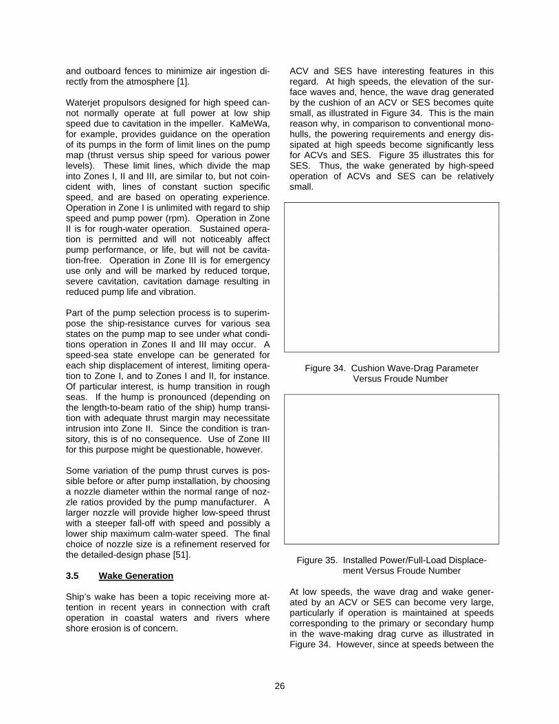
ACV and SES have interesting features in this regard. At high speeds, the elevation of the sur-face waves and, hence, the wave drag generated by the cushion of an ACV or SES becomes quite small, as illustrated in Figure 34. This is the main reason why, in comparison to conventional mono-hulls, the powering requirements and energy dis-sipated at high speeds become significantly less for ACVs and SES. Figure 35 illustrates this for SES. Thus, the wake generated by high-speed operation of ACVs and SES can be relatively small.
Figure 34. Cushion Wave-Drag Parameter Versus Froude Number
Figure 35. Installed Power/Full-Load Displace- ment Versus Froude Number
At low speeds, the wave drag and wake gener-ated by an ACV or SES can become very large, particularly if operation is maintained at speeds corresponding to the primary or secondary hump in the wave-making drag curve as illustrated in Figure 34. However, since at speeds between the
27
primary and secondary humps, the wave drag is seen to reduce significantly, operation at such speeds also produces a relatively small wake. Here, the bow and stern waves tend to interfere to cancel each other, since they are close to being equal in magnitude but opposite in phase [46]. From Lamb’s two-dimensional theory, ACVs or SES having uniform cushion pressure distribu-tions make no waves for speeds corresponding to: FN = (gLc)1/2 = (2πη)-1/2 for η= 1, 2, 3, etc. Thus, F1 (= 0.4) corresponds to the trough be-tween the secondary and primary hump speeds predicted by the three-dimensional theory [45] that was used to produce Figure 34. Thus, at speeds below the secondary hump speed, additional “troughs” in the drag curve occur at F2 = 0.28 and F3 = 0.23, etc. All of these are practical operating speeds [46]. The magnitude and nature of the surface eleva-tions produced can be readily predicted by nu-merically integrating the equations of References [47] and [48]. The results are illustrated in Figure 36, and have been validated by full-scale meas-urements. Thus, the magnitude of the wake and the selection of the speed to minimize the wake of an ACV or SES can be readily determined.
Figure 36. Computed Wave Pattern Developed by an ACV at FN = 0.4 (Vertical Scale Exaggerated)
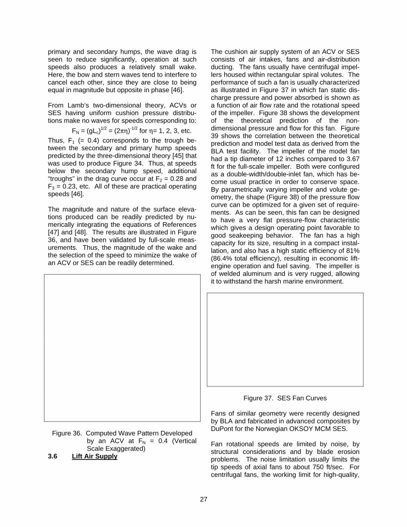
3.6 Lift Air Supply
The cushion air supply system of an ACV or SES consists of air intakes, fans and air-distribution ducting. The fans usually have centrifugal impel-lers housed within rectangular spiral volutes. The performance of such a fan is usually characterized as illustrated in Figure 37 in which fan static dis-charge pressure and power absorbed is shown as a function of air flow rate and the rotational speed of the impeller. Figure 38 shows the development of the theoretical prediction of the non-dimensional pressure and flow for this fan. Figure 39 shows the correlation between the theoretical prediction and model test data as derived from the BLA test facility. The impeller of the model fan had a tip diameter of 12 inches compared to 3.67 ft for the full-scale impeller. Both were configured as a double-width/double-inlet fan, which has be-come usual practice in order to conserve space. By parametrically varying impeller and volute ge-ometry, the shape (Figure 38) of the pressure flow curve can be optimized for a given set of require-ments. As can be seen, this fan can be designed to have a very flat pressure-flow characteristic which gives a design operating point favorable to good seakeeping behavior. The fan has a high capacity for its size, resulting in a compact instal-lation, and also has a high static efficiency of 81% (86.4% total efficiency), resulting in economic lift-engine operation and fuel saving. The impeller is of welded aluminum and is very rugged, allowing it to withstand the harsh marine environment.
Figure 37. SES Fan Curves Fans of similar geometry were recently designed by BLA and fabricated in advanced composites by DuPont for the Norwegian OKSOY MCM SES. Fan rotational speeds are limited by noise, by structural considerations and by blade erosion problems. The noise limitation usually limits the tip speeds of axial fans to about 750 ft/sec. For centrifugal fans, the working limit for high-quality,
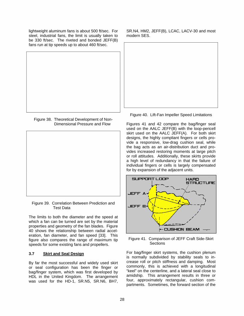
28
lightweight aluminum fans is about 500 ft/sec. For steel, industrial fans, the limit is usually taken to be 330 ft/sec. The riveted and bonded JEFF(B) fans run at tip speeds up to about 460 ft/sec.
Figure 38. Theoretical Development of Non- Dimensional Pressure and Flow
Figure 39. Correlation Between Prediction and Test Data
The limits to both the diameter and the speed at which a fan can be turned are set by the material properties and geometry of the fan blades. Figure 40 shows the relationship between radial accel-eration, fan diameter, and fan speed [33]. This figure also compares the range of maximum tip speeds for some existing fans and propellers. 3.7 Skirt and Seal Design By far the most successful and widely used skirt or seal configuration has been the finger or bag/finger system, which was first developed by HDL in the United Kingdom. The arrangement was used for the HD-1, SR.N5, SR.N6, BH7,
SR.N4, HM2, JEFF(B), LCAC, LACV-30 and most modern SES.
Figure 40. Lift-Fan Impeller Speed Limitations Figures 41 and 42 compare the bag/finger seal used on the AALC JEFF(B) with the loop-pericell skirt used on the AALC JEFF(A). For both skirt designs, the highly compliant fingers or cells pro-vide a responsive, low-drag cushion seal, while the bag acts as an air-distribution duct and pro-vides increased restoring moments at large pitch or roll attitudes. Additionally, these skirts provide a high level of redundancy in that the failure of individual fingers or cells is largely compensated for by expansion of the adjacent units. Figure 41. Comparison of JEFF Craft Side-Skirt
Sections For bag/finger skirt systems, the cushion plenum is normally subdivided by stability seals to in-crease roll or pitch stiffness and damping. Most commonly, this is achieved with a longitudinal “keel” on the centerline, and a lateral seal close to amidship. This arrangement results in three or four, approximately rectangular, cushion com-partments. Sometimes, the forward section of the
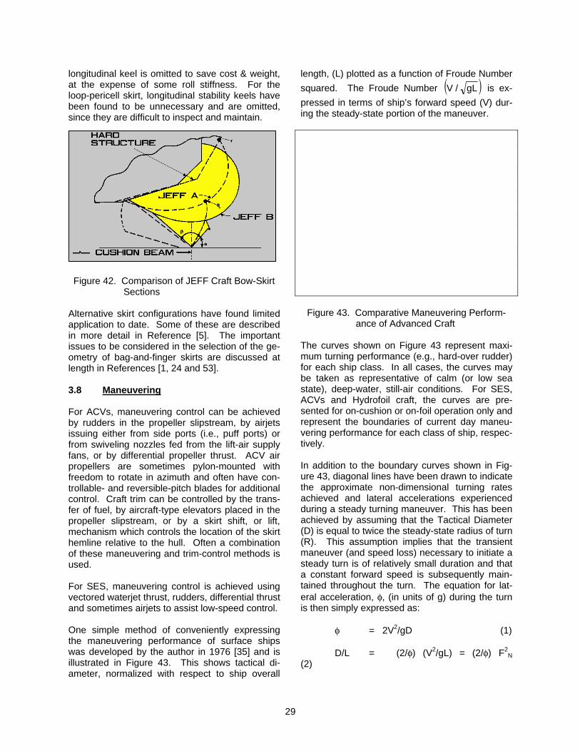
29
longitudinal keel is omitted to save cost & weight, at the expense of some roll stiffness. For the loop-pericell skirt, longitudinal stability keels have been found to be unnecessary and are omitted, since they are difficult to inspect and maintain.
Figure 42. Comparison of JEFF Craft Bow-Skirt
Sections Alternative skirt configurations have found limited application to date. Some of these are described in more detail in Reference [5]. The important issues to be considered in the selection of the ge-ometry of bag-and-finger skirts are discussed at length in References [1, 24 and 53]. 3.8 Maneuvering For ACVs, maneuvering control can be achieved by rudders in the propeller slipstream, by airjets issuing either from side ports (i.e., puff ports) or from swiveling nozzles fed from the lift-air supply fans, or by differential propeller thrust. ACV air propellers are sometimes pylon-mounted with freedom to rotate in azimuth and often have con-trollable- and reversible-pitch blades for additional control. Craft trim can be controlled by the trans-fer of fuel, by aircraft-type elevators placed in the propeller slipstream, or by a skirt shift, or lift, mechanism which controls the location of the skirt hemline relative to the hull. Often a combination of these maneuvering and trim-control methods is used. For SES, maneuvering control is achieved using vectored waterjet thrust, rudders, differential thrust and sometimes airjets to assist low-speed control. One simple method of conveniently expressing the maneuvering performance of surface ships was developed by the author in 1976 [35] and is illustrated in Figure 43. This shows tactical di-ameter, normalized with respect to ship overall
length, (L) plotted as a function of Froude Number squared. The Froude Number ( )gL/V is ex-pressed in terms of ship’s forward speed (V) dur-ing the steady-state portion of the maneuver.
Figure 43. Comparative Maneuvering Perform- ance of Advanced Craft
The curves shown on Figure 43 represent maxi-mum turning performance (e.g., hard-over rudder) for each ship class. In all cases, the curves may be taken as representative of calm (or low sea state), deep-water, still-air conditions. For SES, ACVs and Hydrofoil craft, the curves are pre-sented for on-cushion or on-foil operation only and represent the boundaries of current day maneu-vering performance for each class of ship, respec-tively. In addition to the boundary curves shown in Fig-ure 43, diagonal lines have been drawn to indicate the approximate non-dimensional turning rates achieved and lateral accelerations experienced during a steady turning maneuver. This has been achieved by assuming that the Tactical Diameter (D) is equal to twice the steady-state radius of turn (R). This assumption implies that the transient maneuver (and speed loss) necessary to initiate a steady turn is of relatively small duration and that a constant forward speed is subsequently main-tained throughout the turn. The equation for lat-eral acceleration, φ, (in units of g) during the turn is then simply expressed as: φ = 2V2/gD (1) D/L = (2/φ) (V2/gL) = (2/φ) F2
N (2)
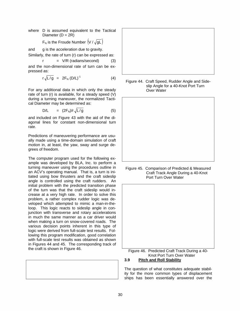
30
where D is assumed equivalent to the Tactical Diameter (D = 2R)
FN is the Froude Number ( )gL/V
and g is the acceleration due to gravity. Similarly, the rate of turn (r) can be expressed as: r = V/R (radians/second) (3) and the non-dimensional rate of turn can be ex-pressed as:
r g/L = 2FN (D/L)-1 (4)
For any additional data in which only the steady rate of turn (r) is available, for a steady speed (V) during a turning maneuver, the normalized Tacti-cal Diameter may be determined as:
D/L = (2FN)/r g/L (5)
and included on Figure 43 with the aid of the di-agonal lines for constant non-dimensional turn rate. Predictions of maneuvering performance are usu-ally made using a time-domain simulation of craft motion in, at least, the yaw, sway and surge de-grees of freedom. The computer program used for the following ex-ample was developed by BLA, Inc. to perform a turning maneuver using the procedures outline in an ACV’s operating manual. That is, a turn is ini-tiated using bow thrusters and the craft sideslip angle is controlled using the craft rudders. An initial problem with the predicted transition phase of the turn was that the craft sideslip would in-crease at a very high rate. In order to solve this problem, a rather complex rudder logic was de-veloped which attempted to mimic a man-in-the-loop. This logic reacts to sideslip angle in con-junction with transverse and rotary accelerations in much the same manner as a car driver would when making a turn on snow-covered roads. The various decision points inherent in this type of logic were derived from full-scale test results. Fol-lowing this program modification, good correlation with full-scale test results was obtained as shown in Figures 44 and 45. The corresponding track of the craft is shown in Figure 46.
Figure 44. Craft Speed, Rudder Angle and Side-
slip Angle for a 40-Knot Port Turn Over Water
Figure 45. Comparison of Predicted & Measured
Craft Track Angle During a 40-Knot Port Turn Over Water
Figure 46. Predicted Craft Track During a 40- Knot Port Turn Over Water
3.9 Pitch and Roll Stability The question of what constitutes adequate stabil-ity for the more common types of displacement ships has been essentially answered over the
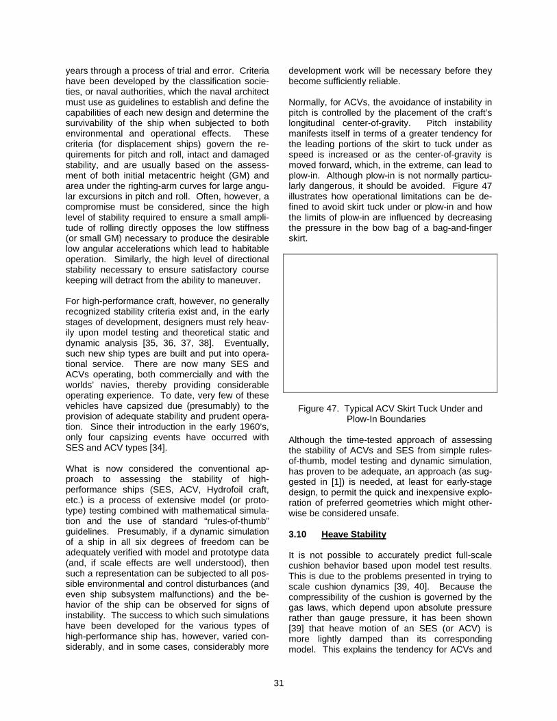
31
years through a process of trial and error. Criteria have been developed by the classification socie-ties, or naval authorities, which the naval architect must use as guidelines to establish and define the capabilities of each new design and determine the survivability of the ship when subjected to both environmental and operational effects. These criteria (for displacement ships) govern the re-quirements for pitch and roll, intact and damaged stability, and are usually based on the assess-ment of both initial metacentric height (GM) and area under the righting-arm curves for large angu-lar excursions in pitch and roll. Often, however, a compromise must be considered, since the high level of stability required to ensure a small ampli-tude of rolling directly opposes the low stiffness (or small GM) necessary to produce the desirable low angular accelerations which lead to habitable operation. Similarly, the high level of directional stability necessary to ensure satisfactory course keeping will detract from the ability to maneuver. For high-performance craft, however, no generally recognized stability criteria exist and, in the early stages of development, designers must rely heav-ily upon model testing and theoretical static and dynamic analysis [35, 36, 37, 38]. Eventually, such new ship types are built and put into opera-tional service. There are now many SES and ACVs operating, both commercially and with the worlds’ navies, thereby providing considerable operating experience. To date, very few of these vehicles have capsized due (presumably) to the provision of adequate stability and prudent opera-tion. Since their introduction in the early 1960’s, only four capsizing events have occurred with SES and ACV types [34]. What is now considered the conventional ap-proach to assessing the stability of high-performance ships (SES, ACV, Hydrofoil craft, etc.) is a process of extensive model (or proto-type) testing combined with mathematical simula-tion and the use of standard “rules-of-thumb” guidelines. Presumably, if a dynamic simulation of a ship in all six degrees of freedom can be adequately verified with model and prototype data (and, if scale effects are well understood), then such a representation can be subjected to all pos-sible environmental and control disturbances (and even ship subsystem malfunctions) and the be-havior of the ship can be observed for signs of instability. The success to which such simulations have been developed for the various types of high-performance ship has, however, varied con-siderably, and in some cases, considerably more
development work will be necessary before they become sufficiently reliable. Normally, for ACVs, the avoidance of instability in pitch is controlled by the placement of the craft’s longitudinal center-of-gravity. Pitch instability manifests itself in terms of a greater tendency for the leading portions of the skirt to tuck under as speed is increased or as the center-of-gravity is moved forward, which, in the extreme, can lead to plow-in. Although plow-in is not normally particu-larly dangerous, it should be avoided. Figure 47 illustrates how operational limitations can be de-fined to avoid skirt tuck under or plow-in and how the limits of plow-in are influenced by decreasing the pressure in the bow bag of a bag-and-finger skirt.
Figure 47. Typical ACV Skirt Tuck Under and Plow-In Boundaries
Although the time-tested approach of assessing the stability of ACVs and SES from simple rules-of-thumb, model testing and dynamic simulation, has proven to be adequate, an approach (as sug-gested in [1]) is needed, at least for early-stage design, to permit the quick and inexpensive explo-ration of preferred geometries which might other-wise be considered unsafe. 3.10 Heave Stability It is not possible to accurately predict full-scale cushion behavior based upon model test results. This is due to the problems presented in trying to scale cushion dynamics [39, 40]. Because the compressibility of the cushion is governed by the gas laws, which depend upon absolute pressure rather than gauge pressure, it has been shown [39] that heave motion of an SES (or ACV) is more lightly damped than its corresponding model. This explains the tendency for ACVs and
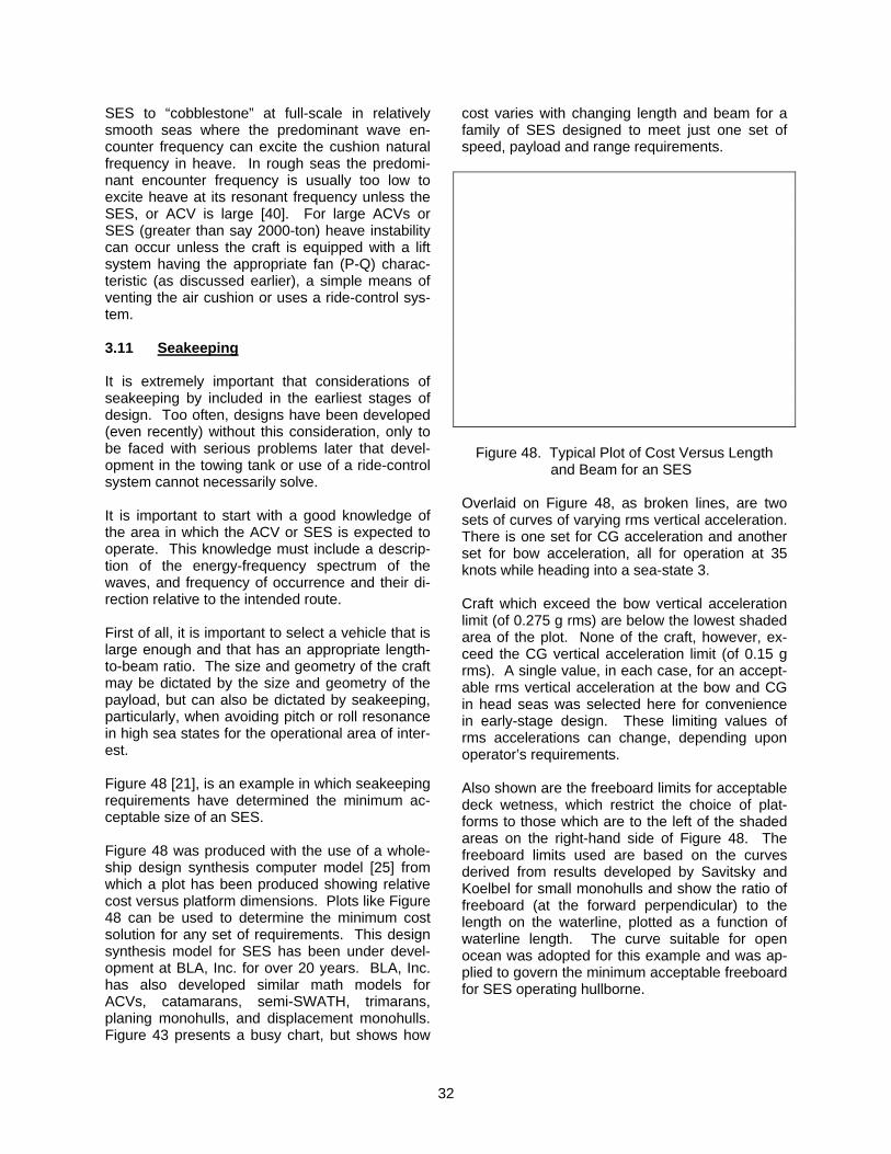
32
SES to “cobblestone” at full-scale in relatively smooth seas where the predominant wave en-counter frequency can excite the cushion natural frequency in heave. In rough seas the predomi-nant encounter frequency is usually too low to excite heave at its resonant frequency unless the SES, or ACV is large [40]. For large ACVs or SES (greater than say 2000-ton) heave instability can occur unless the craft is equipped with a lift system having the appropriate fan (P-Q) charac-teristic (as discussed earlier), a simple means of venting the air cushion or uses a ride-control sys-tem. 3.11 Seakeeping It is extremely important that considerations of seakeeping by included in the earliest stages of design. Too often, designs have been developed (even recently) without this consideration, only to be faced with serious problems later that devel-opment in the towing tank or use of a ride-control system cannot necessarily solve. It is important to start with a good knowledge of the area in which the ACV or SES is expected to operate. This knowledge must include a descrip-tion of the energy-frequency spectrum of the waves, and frequency of occurrence and their di-rection relative to the intended route. First of all, it is important to select a vehicle that is large enough and that has an appropriate length-to-beam ratio. The size and geometry of the craft may be dictated by the size and geometry of the payload, but can also be dictated by seakeeping, particularly, when avoiding pitch or roll resonance in high sea states for the operational area of inter-est. Figure 48 [21], is an example in which seakeeping requirements have determined the minimum ac-ceptable size of an SES. Figure 48 was produced with the use of a whole-ship design synthesis computer model [25] from which a plot has been produced showing relative cost versus platform dimensions. Plots like Figure 48 can be used to determine the minimum cost solution for any set of requirements. This design synthesis model for SES has been under devel-opment at BLA, Inc. for over 20 years. BLA, Inc. has also developed similar math models for ACVs, catamarans, semi-SWATH, trimarans, planing monohulls, and displacement monohulls. Figure 43 presents a busy chart, but shows how
cost varies with changing length and beam for a family of SES designed to meet just one set of speed, payload and range requirements.
Figure 48. Typical Plot of Cost Versus Length and Beam for an SES
Overlaid on Figure 48, as broken lines, are two sets of curves of varying rms vertical acceleration. There is one set for CG acceleration and another set for bow acceleration, all for operation at 35 knots while heading into a sea-state 3. Craft which exceed the bow vertical acceleration limit (of 0.275 g rms) are below the lowest shaded area of the plot. None of the craft, however, ex-ceed the CG vertical acceleration limit (of 0.15 g rms). A single value, in each case, for an accept-able rms vertical acceleration at the bow and CG in head seas was selected here for convenience in early-stage design. These limiting values of rms accelerations can change, depending upon operator’s requirements. Also shown are the freeboard limits for acceptable deck wetness, which restrict the choice of plat-forms to those which are to the left of the shaded areas on the right-hand side of Figure 48. The freeboard limits used are based on the curves derived from results developed by Savitsky and Koelbel for small monohulls and show the ratio of freeboard (at the forward perpendicular) to the length on the waterline, plotted as a function of waterline length. The curve suitable for open ocean was adopted for this example and was ap-plied to govern the minimum acceptable freeboard for SES operating hullborne.
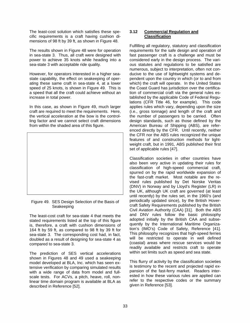
33
The least-cost solution which satisfies these spe-cific requirements is a craft having cushion di-mensions of 98 ft by 39 ft, as shown in Figure 48. The results shown in Figure 48 were for operation in sea-state 3. Thus, all craft were designed with power to achieve 35 knots while heading into a sea-state 3 with acceptable ride quality. However, for operators interested in a higher sea-state capability, the effect on seakeeping of oper-ating these same craft in sea-state 4, at a lower speed of 25 knots, is shown in Figure 49. This is a speed that all the craft could achieve without an increase in total power. In this case, as shown in Figure 49, much larger craft are required to meet the requirements. Here, the vertical acceleration at the bow is the control-ling factor and we cannot select craft dimensions from within the shaded area of this figure. Figure 49. SES Design Selection of the Basis of
Seakeeping The least-cost craft for sea-state 4 that meets the stated requirements listed at the top of this figure is, therefore, a craft with cushion dimensions of 164 ft by 59 ft, as compared to 98 ft by 39 ft for sea-state 3. The corresponding cost had, in fact, doubled as a result of designing for sea-state 4 as compared to sea-state 3. The prediction of SES vertical accelerations shown in Figures 48 and 49 used a seakeeping model developed at BLA, Inc. which has seen ex-tensive verification by comparing simulated results with a wide range of data from model and full-scale tests. For ACVs, a pitch, heave, roll, non-linear time domain program is available at BLA as described in Reference [52].
3.12 Commercial Regulation and Classification
Fulfilling all regulatory, statutory and classification requirements for the safe design and operation of fast passenger craft is a challenge and must be considered early in the design process. The vari-ous statutes and regulations to be satisfied are numerous, subject to interpretation, often not con-ducive to the use of lightweight systems and de-pendent upon the country in which (or to and from which) the craft will operate. In the United States the Coast Guard has jurisdiction over the certifica-tion of commercial craft via the general rules es-tablished by the applicable Code of Federal Regu-lations (CFR Title 46, for example). This code applies rules which vary, depending upon the size (i.e., gross tonnage) and length of the craft and the number of passengers to be carried. Often design standards, such as those defined by the American Bureau of Shipping (ABS), are refer-enced directly by the CFR. Until recently, neither the CFR nor the ABS rules recognized the unique features of and construction methods for light-weight craft, but in 1991, ABS published their first set of applicable rules [47]. Classification societies in other countries have also been very active in updating their rules for classification of high-speed commercial craft, spurred on by the rapid worldwide expansion of the fast-craft market. Most notable are the re-vised rules published by Det Norske Veritas (DNV) in Norway and by Lloyd’s Register (LR) in the UK, although UK craft are governed (at least until recently) by the rules set, in the 1960’s (and periodically updated since), by the British Hover-craft Safety Requirements published by the British Civil Aviation Authority (CAA) [31]. Both the ABS and DNV rules follow the basic philosophy adopted initially by the British CAA and subse-quently by the International Maritime Organiza-tion’s (IMO’s) Code of Safety, Reference [41]. This philosophy recognizes that high-speed ferries will be restricted to operate in well defined (coastal) areas where rescue services would be readily available and restricts craft to operate within set limits such as speed and sea state. This flurry of activity by the classification societies is testimony to the recent and projected rapid ex-pansion of the fast-ferry market. Readers inter-ested in how these various rules are applied can refer to the respective codes or the summary given in Reference [53].
34
4.0 SUMMARY AND CONCLUSIONS This paper has reviewed the history of major de-velopments of ACV and SES design, and the op-tions available to, and the constraints imposed on, the designer. With a few exceptions, ACV and SES design technologies are mature and we are now taking advantage of this as we enter an era of renewed hovercraft activity in North America, Europe and the Far East. The fleet of over 90 Navy assault landing craft, LCACs, are now in operation; the Norwegian Navy has most of their MCM SES in operation; the Swedish Navy is con-sidering stealth SES like the ABS M10; the 1500-ton SES “KIBO” is being evaluated in Japan; South Korea is now building SES; and the Cana-dian Coast Guard has recently taken delivery of the new ACV DASH 400. With the expected rapid growth in experience gained from such programs of construction and operation, we anticipate a continued improvement in the technology base which will ensure the future growth in the use of these craft. ACVs and SES are competing with planing craft, fast catamarans, wave piercers and hydrofoils (with fully-submerged or surface-piercing foil sys-tems), as well as the slower conventional ferries. There appears to be considerable semantic con-fusion in the minds of potential operators and builders, regarding distinctions between the vari-ous catamarans, SWATH, semi-SWATH, and SES designs [1]. The essential parameters of a successful opera-tion are cost, comfort and speed. “Convenience” may also be considered as a factor in the sense that amphibious ACVs may more effectively ac-cess shore connections and the increased draft of hydrofoils and SWATH may restrict their opera-tions in shallow waters. Generally, increased speed and/or comfort will increase the cost per passenger mile. In most applications, comfort tends to be more important than speed. The ma-jority of current ferry routes are two hours or less in duration and are associated with traffic and queuing delays on either end, which diminish the importance of small time savings. Given a choice, few passengers will return, however, after a bout of seasickness or the discomfort of a noise cramped passage with an ability to move about the cabin. There are a number of quantitative measures (rms acceleration, roll period, etc.) which are applied to define acceptable motions, but true measures of passenger satisfaction are elusive and, in the final analysis, only ridership
and profit balance will determine the success of an operation. Speed, which could exceed 60 knots but more practically would be in the 40 to 55 knot range, is the most obvious near-term military advantage of the ACV or SES [1]. With careful design and in-stallation of state-of-the-art ride-control systems, SES (or ACVs) offer significant seakeeping im-provements over equivalent monohulls. There are other advantages, depending on the mission. For MCM, shock attenuation is most important. In the case of the U.S. Coast Guard SES, which had operational speeds only a little over 30 knots, plat-form stability during long hours of loiter on drug-interdiction patrols made these craft the most popular cutters in the fleet from a habitability standpoint. The twin-hull configuration and shal-low draft introduced survivability/vulnerability benefits. SES deck area is particularly generous, as is enclosed volume, since designs are gener-ally volume and not weight-driven. Excess vol-ume is desirable where modular concepts are considered. It is clear that the key to the success of the ACV will continue to be the exploitation of its speed and the many advantages of its amphibious capability. The success of the ACV can be attributed to de-velopments in technology which have provided improved efficiency, improved controllability and reduced operating costs. Advances in skirt de-sign, lift fan and propeller design, the develop-ment of bow thrusters, all-welded marine alumi-num hulls, and lightweight composites have all contributed significantly to this success. In the past, ACVs have been expensive largely due to machinery costs. Gas turbine engines, controllable pitch propellers, and high-speed lightweight transmissions are all expensive. The BHC AP.1-88 and ABS M10, which utilize air-cooled diesel engines, fixed-pitch propellers, and a toothed-belt drive, are examples of an approach to a much less expensive ACV. Trends such as these, plus continued improvements in basic technology, will ensure the future growth in the use of these versatile craft. The performance of an SES or ACV, and other high-performance craft, is more sensitive to weight than the performance of conventional low-speed craft. Thus, there is always a motivation to find acceptably reliable subsystems of minimum possible weight, albeit at a higher price. This has been construed, in some circles, as a major dis-
35
advantage for ACVs or SES. However, we prefer to view the ACV or SES as craft that can take cost-effective advantage of using lightweight sys-tems, unlike most other marine craft (and, particu-larly, unlike Monohulls). What seemingly little mo-tivation there has been in the marine industry to develop lightweight systems (for power plants, transmission systems, structures, outfitting, auxil-iary systems, etc.) has resulted, however, in very significant progress over the years, and at a rate which is continuing. For example, without high power-to-weight diesel engines and the use of aluminum alloy or foam-core FRP for hull struc-ture, all of the total power-to-weight advantage of SES (and ACVs), shown in Figure 32 would not have been possible. As further progress is made to develop even lighter systems, the advantage for the SES and ACV will increase. 5.0 REFERENCES 1. Lavis, D.R., “Hovercraft Development,” Inter-
society High-Performance Marine Vehicle Conference and Exhibit, Arlington, Virginia, June 24-27, 1992.
2. Hayward, L., “The History of Air Cushion Ve-
hicles,” Kalerghi McCleary Publications, Lon-don, 1963.
3. Crewe, P.R. and Eggington, W.J., “The
Hovercraft - A New Concept in Maritime Transport,” RINA, November 19, 1959.
4. Trillo, R.L., “Marine Hovercraft Technology,”
book published by Leonard Hill Books, Lon-don, 1971.
5. Mantle, P.J., “Air Cushion Craft Develop-
ment,” book published by DTNSRDC, No. 80/012 (4727 Revised), 1980.
6. “Janes High-Speed Marine Transportation,”
(Issues 1971 to 1998), Jane’s Information Group Ltd, Editor, Robert Trillo; Sentinel House, 163 Brighton Road, Coulsdon, Surrey, CR5 2NH, UK.
7. “Fast Ferry International,” formally “High-
Speed Surface Craft,” and “Hovering Craft and Hydrofoil,” (Issues 1961 to 1990), High-Speed Surface Craft Ltd, Editor Alan Blunden, 24 Leaf Close Northwood, Middlesex, HA6 2YY, UK.
8. “Air-Cushion Vehicles,” (Issues 1963 to 1971), Horizon Publications Ltd, Somerset, UK (for-mally a Flight International supplement).
9. Tattersall, E.G., “The History and Future of
the Surface Effect Ship in the United King-dom, A Personal Account,” Naval Engineers Journal, Volume 94, Number 2, ASNE, April 1982.
10. Ford, A.G., “Captured Air Bubble (CAB) Vehi-
cle Progress Report, AIAA Journal of Hydro-nautics, April 1968.
11. Bertelsen, W.R., “Thirty Years of Research
and Development of Air Cushion Vehicles,” In-tersociety Advanced Marine Vehicle Confer-ence, Arlington, Virginia, June 5-7, 1989.
12. Benya, Y.Y. and D’yachenko, V.K., “Basic
Theories of Air Cushion Vehicles,” Army Ma-teriel Command, U.S. Army Foreign Science and Technology Center No. FSTC-HT-23-496-71, October 1971, NTIS No. AD742 425.
13. Wilkins, D.L. and Plackett, M.J., “Develop-
ment of the U.S. Army’s Pontoon Air Cushion Kit (PACK),” Hovercraft Symposium, Septem-ber 1988.
14. Wilkins, D.L., “Development of PACK for the
Causeway Emplacement Mission,” February 1990.
15. Wilkins, D.L. and Dowty, M.B., “The Integra-
tion of Modular Pontoon Systems and Air-Cushion Technology for Application to U.S. Army Logistics-Over-The-Shore Missions,” Chesapeake Section of SNAME, October 1989.
16. Tattersall, E.G., “The History and Future of
the Surface Effect Ship in the United King-dom, A Personal Account,” Naval Engineers Journal, Volume 94, Number 2, ASNE, April 1982.
17. Tattersall, E.G., “The HM 500 Series of Side-
wall Hovercraft,” Royal Institution of Naval Ar-chitects, April 1984.
18. Chaplin, J.B., “A Rational Approach to an SES
Design,” AIAA/SNAME Advanced marine Ve-hicle Conference, Paper No. 79-2032, Octo-ber 1979.
36
19. White, W.N., “Advanced Marine Vehicles - A Review,” Section III Surface Effect Ship (SES), 23rd Annual Technical Symposium, NAVSEA, Association of Scientists and Engi-neers, April 1986.
20. Adams, J.D. and Beverly, W.F., “Technical
Evaluation of the SES-200 High Length-to-Beam Surface Effect Ship,” Naval Engineers Journal, Volume 96, Number 3, May 1984.
21. Lavis, D.R., Rogalski, W.W., and Spaulding,
K.B., “The Promise of Advanced Naval Vehi-cles for NATO,” Marine Technology, March 1990.
22. Kenefick, R.W., “Managing LCAC in the
Evolving Acquisition Environment,” CACTS, September 1985.
23. Oehlmann, H. and Lewthwaite, J.C., “The
Prediction of Resistance of Surface Effect Ships,” FAST 91, Trondheim, Norway.
24. Lavis, D.R., “Advanced Marine Vehicles - A
Review,” Section IV - Air Cushion Vehicles, “Workshop on Hullform Design,” MARIN, Wageningen, Netherlands, October 22-24, 1985.
25. Lavis, D.R. and Forstell, B.G., “Computer-
Aided Conceptual Design of Surface-Effect Ships,” Canadian Aeronautics and Space Journal, Volume 35, No. 2, June 1989.
26. Band, E.G.U. and Lavis, D.R., “Computer-
Aided Design of Air-Cushion Vehicles and Surface-Effect Ships,” International High-Performance Vehicle Conference, Shanghai, November 1988.
27. Lavis, D.R. and Bagnell, D.G., “Computer-
Aided Early-Stage Design of High Speed Craft,” Intersociety Conference, Arlington, Vir-ginia, June 1989.
28. Band, E.G.U., Lavis, D.R., and Giannotti,
“Prediction of Hydrodynamic Impact Loads Acting on SES and ACV Structures,” AIAA Paper 76-868, September 1976.
29. Band, E.G.U. and Baca, A.F., “Predicting the
Unpredictable - Development of Rational De-sign Loads for High-Performance Vessels,” Hovering Craft and Hydrofoil Exhibition, Brigh-ton, England, June 1980.
30. “Rules for Classification of High-Speed Craft,”
Det Norske Veritas, 1985 (Draft Revision Is-sued for Review, January 1990).
31. “British Hovercraft Safety Requirements,” Civil
Aviation Authority, Surrey, England. 32. “ABS Rules for High-Speed Craft,” American
Bureau of Shipping, 1991. 33. Moore, R.G. and Omega, G.T., Bell Aero-
space Textron, "Large SES Design Limits,” ATAA, Spring 1979.
34. “Report of the ARB Special Committee on
Hovercraft Stability and Control,” Civil Aviation Authority, CAA Report 75017, June 1975.
35. Lavis, D.R., “The Comparative Maneuvering
Capability and Stability of Surface Ships,” Payne Inc., Working Paper No. 196-9, Octo-ber 1976.
36. Lavis, D.R., Band, E.G.U. and Hoyt, E.D.,
“Development of Intact Stability Standards for Rigid Sidehull Surface-Effect Ships,” USCG Report No. CG-D-53-81, December 1981.
37. Blyth, A., “Recent Research into the Ultimate
Stability of Surface-Effect Ships,” RINA Con-ference on Ship Stability and Safety, June 1986.
38. Wilson, R.A., “Captured Air Bubble Vehicle
Stability Tests,” AIAA/SNAME Advanced Ma-rine Vehicle Meeting, Norfolk, Virginia, Report No. 67-349, May 1967.
39. Lavis, D.R., Bartholomew, R.J. and Jones,
J.C., “On the Prediction of Acceleration Re-sponse of Air Cushion Vehicles to Random Seaways and the Distortion Effects of the Cushion Inherent in Scale Models,” AIAA Pa-per 72-598, July 1972.
40. Band, E.G.U. and Lavis, D.R., “Heave Stabil-
ity of Air-Cushion Supported Ships,” PRADS’ 89 Conference, Varna, Bulgaria, October 1989.
41. “International Code of Safety for High-Speed
Craft," International Maritime Organization, 1995.
37
42. Work Boat World, Page 10, by George Marsh. Published by Baird Publications, Eastgate House, Town Quay, Southampton, SO1 LX, UK
43. Watson, J.A. and Hayden, W.M., “Overview of
Coast Guard Plan Review for High-Tech Ship Design,” paper presented to the Chesapeake Section of SNAME, 22 February 1989.
44. “Leisure Industries Promote Increased Activ-
ity,” The Motor Ship, January 1991. 45. Doctors, L.J., “The Wave Resistance of an Air
Cushion Vehicle,” University of Michigan, De-cember 1970.
46. Tuck, E.O., “Ship-Hydrodynamic Free-Surface
Problems Without Waves,” Journal of Ship Research, SNAME, Volume 35, No. 4, pages 277-287, December 1991.
47. Huang, T.T., Wong, K.K., and Webster, W.C.,
“On the Flow Field Beneath a Moving Pres-sure Distribution Over the Sea,” Hydronautics, Inc., Technical Report 709-1, December 1967.
48. Huang, T.T. and Wong, K.K., “Disturbance
Induced by a Pressure Distribution Moving
Over a Free Surface,” Journal of Ship Re-search, September 1970.
49. Allison, J.L., “Propellers for High-Performance
Craft,” Marine Technology, October 1978. 50. Lavis, D.R., “Air Cushion Craft,” Chapter VII of
“Modern Ships and Craft,” Naval Engineers Journal, Special Edition, ASNE, February 1985.
51. Allison, J.L., “Marine Waterjet Propulsion,”
Chesapeake Section of SNAME, September 15, 1992.
52. Lavis, D.R., Forstell, B.G. and Jiang C., “Ad-
vanced Hovercraft - Skirt Technology,” RINA, London, UK, December 1997.
53. “A Guide for Implementing High-Speed Wa-
terborne Passenger Transportation Services,” Urban Mass Transportation Administration, Office of Technical Assistance, September 1984.
54. Lavis, D.R. and Spaulding, K.B., Jr., “Surface
Effect Ship (SES) Developments Worldwide,” Naval Engineers Journal, Volume 103, Num-ber 5, ASNE, September 1991.