Embed Size (px)
Citation preview

FORMULATION A DUAL EFFECT NATURAL DRAG REDUCTION AGENT
SITI NURAFFINI BINTI KAMARULIZAM
Thesis submitted in fulfillment of the requirements for the award of the degree of
Master of Engineering in Chemical
Faculty of Chemical and Natural Resources Engineering
UNIVERSITI MALAYSIA PAHANG
AUGUST 2012

ACKNOWLEDGEMENTS Praise to Allah SWT to His willingness to give me an opportunity and strength to complete my Master Degree thesis. Predominantly, I would like to express my sincerest appreciation to PM Dr Hayder A. Abdulbari, for his supervisions, guidance, encouragements, and patience while supervising the progress of my research project from its initial phases till the completion of thesis. He thought me a lot especially related on researches, publishing papers, attending conference and much more. Without his supports, I would not be able complete this research successfully. He has always impressed me with his outstanding professional conduct, thought, and skills. From him, I learned a lot of new big prospect that I never thought before. I would like to extend my biggest gratitude to National Sciences Fellowship under Ministry of Sciences, Technology and Innovation for funding my Master study. My sincere thanks also go to Universiti Malaysia Pahang for providing facilities for me to accomplish my study. I would also like to thank my friends for providing support and assistance at various occasions in order to complete my study. Not forgetting to lecturers, administrative officers, technical teams, and everyone who support, believe and assist me to achieve my Master Degree. Last but definitely not least, family members and closest acquaintances, and not forgotten for my love one, Muhammad Amir for your worships, and for the audaciousness, as well as supporting me throughout carrying out my studies and my life.
ABSTRACT
Transporting liquids in pipelines is considered as one of the most economically feasible methods due to the controlled and safe media these liquids are transported within. The transportation of liquids through strategic pipelines and for hundreds of kilometers is also considered as one of the most power consuming sectors due to the turbulent mode these liquids are transported with. Additional supporting pumping station along the pipeline was one of the solutions applied, but its application added an additional cost to the total cost of transportation. The addition of polymeric additives to the main flow was proven to be a successful solution to the pumping power dissipation in pipelines due to the visco-elastic properties of these polymers that can suppress the turbulent structures inside the pipe. Most of these polymeric additives are not biodegradable and not environmentally friendly. In this present work, a new environmental friendly, soluble and insoluble Drag Reducing Agents (DRA) is introduced. These new additives are driven from plant and byproduct of tin industries which are okra mucilage from lady finger and slag particles. The drag reduction performances of the new additives were tested in water and hydrocarbon media. The water-soluble okra mucilage and the slag powder drag reduction performance were tested in water solution. To test the okra mucilage in hydrocarbon solution, the solubility of the original okra mucilage was changed using grafting co-polymerization technique. The objective of this research is to investigate the effect of this novel DRA based on classical parameters which are additive concentration, fluid velocity, internal pipe diameter and pipe length. Experimental closed loop circulation rig consisted of three different pipes diameter (0.0381m D.I, 0.0254m D.I and 0.0127m D.I) with 2.0m pipe length were setup in order to accomplish the objectives. The transported solution was flowing through pipelines from tank into required testing section for pressure drop determination. A ball valve located at recirculation pipes used to control the flow rate of solution entering testing section the flow meter sensor and pressure sensors located at each testing section will give reading at screen by SCADA software. From experimental results, highest Percentage Drag Reduction (%Dr) were obtained on 0.0381m D.I with 78% flowing through Re equal to 29017.44, 1000ppm and 0.5m pipe length for hydrocarbon liquid and 80% flowing through Re equal to 118235.42, 1000ppm and 0.5m for water as transported media. For slag particles analysis, highest %Dr was obtained on 0.0381m D.I with 70% flowing through Re equal to 29017.44, 1000ppm and 0.5m pipe length. While, for water, highest %Dr where obtained at 0.0381m D.I with 80% flowing through Re = 118235.42, 1000ppm and 0.5m pipe length. The fluid velocity effect give increment and decrement pattern depend on Re-%Dr relation curve. Increasing additive concentration and pipe diameter will increased the %Dr. The %Dr reading for the pipe length effects gives unnoticeable changes. However, it is predicted to decrease for polymeric DRA since the breakup of polymer when facing shear stress. Time consumption shows polymer are able to resist increment of pressure drop at certain period. However, suspended solid DRA show consistent %Dr reading with time consumption. A mathematical expression by using STATISTICA software was developed to delineate and verified the real mechanism of Drag Reduction (DR). As a conclusion, new greener DRA were successfully introduced and its effectiveness in improving the flow was proven experimentally.

ABSTRAK
Pengangkutan bendalir di dalam saluran paip dianggap sebagai salah satu kaedah yang terbaik dari segi ekonomi kerana bendalir berada dalam keadaan paling selamat dan terkawal. Walau bagaimanapun, pengangkutan bendalir melalui saluran paip sepanjang ratusan kilometer dianggap sebagai salah satu sektor yang menggunakan tenaga kuasa yang tinggi kerana aliran yang bergelora. Salah satu penyelesaian adalah dengan menambah stesen pam sokongan. Ini menyebabkan penambahan kos pengangkutan dan penyelenggaraan. Penambahan polimer ke dalam aliran utama telah terbukti menjadi satu penyelesaian yang berjaya kepada pembaziran tenaga kerana sifat likat-kenyal-polimer terbukti menyekat struktur bergelora di dalam paip. Walau bagaimanapun, kebanyakan bahan tambah polimer ini tidak boleh dilupuskan dan tidak mesra alam. Dalam kajian terbaru ini, Egen Pengurangan Seretan (DRA) yang mesra alam, (larut dan tidak larut) diperkenalkan. Bahan tambah ini (DRA) diperoleh dari lendir tumbuhan dan hasil sampingan industri timah. Prestasi pengurangan seretan telah diuji dalam media air dan hidrokarbon. Prestasi Pengurangan Seretan menggunakan lendir bendi dan serbuk sanga telah diuji di dalam larutan air. Untuk menguji lendir bendi dalam larutan hidrokarbon, keterlarutan lendir bendi yang asal telah diubah menggunakan teknik cantuman pempolimeran. Objektif kajian adalah untuk mengkaji kesan DRA berdasarkan parameter klasik iaitu kepekatan bahan tambah, halaju bendalir, diameter dalaman paip dan panjang paip. Pelantar gelung tertutup untuk menjalankan kajian terdiri daripada tiga paip berdiameter berbeza (0.0381m DI, 0.0254m DI dan 0.0127m DI) dengan panjang paip 2.0m adalah persediaan untuk mencapai objektif. Sebatian bendalir dan bahan tambah mengalir melalui saluran paip dari tangki ke bahagian ujian diperlukan untuk menentukan kejatuhan tekanan. Injap bola yang terletak di paip edaran semula yang digunakan untuk mengawal kadar aliran. Sebatian yang dikaji memasuki bahagian aliran bersensor tekanan yang terletak di setiap seksyen kajian akan memberi membaca di skrin dengan perisian SCADA. Daripada keputusan ujikaji, Peratus Pengurangan Seretan (%Dr) tertinggi telah diperolehi pada diameter piap 0.0381m DI dengan 78% yang mengalir melalui Re bersamaan dengan 29017.44, 1000ppm dan 0.5m panjang untuk bendalir hidrokarbon dan 80% yang mengalir melalui Re bersamaan dengan 118235.42, 1000ppm dan 0.5m untuk air sebagai media bendalir. Bagi analisis zarah sanga, %Dr tertinggi diperolehi pada 0.0381m DI dengan 70% yang mengalir melalui Re bersamaan dengan 29017.44, 1000ppm dan 0.5m panjang paip. Sementara itu, bagi air, %Dr tertinggi diperolehi di 0.0381m DI dengan 80% yang mengalir melalui Re bersamaan dengan 118235.42, 1000ppm dan 0.5m panjang paip. Kesan halaju bendalir memberi kenaikan dan penurunan corak bergantung kepada pola perhubungan Re-%Dr. Peningkatan kepekatan bahan tambah dan diameter paip akan meningkatkan % Dr. Keputusan %Dr untuk kesan panjang paip tidak memberi perubahan yang signifikan. Walau bagaimanapun, ia diramalkan berkuran kerana polimer DRA mengalami pemecahan polimer apabila menghadapi tegasan ricih. Penggunaan masa menunjukkan polimer mampu untuk menentang kejatuhan tekanan pada tempoh tertentu. Walau bagaimanapun, zarah tidak larut DRA menunjukkan bacaan %Dr yang konsisten dengan penggunaan masa. Ungkapan matematik dengan menggunakan perisian Statistica telah dibangunkan untuk menggambarkan dan mengesahkan mekanisme sebenar Pengurangan Drag (DR). Sebagai kesimpulan, DRA baru yang lebih hijau telah berjaya diperkenalkan dan terbukti dalam meningkatkan aliran.

TABLE OF CONTENTS
Page
SUPERVISOR’S DECLARATION ii
STUDENT’S DECLARATION iii
DEDICATION iv
ACKNOWLEDGEMENTS v
ABSTRACT vi
ABSTRAK vii
TABLE OF CONTENTS viii-x
LIST OF TABLES xi-xiii
LIST OF FIGURES xv-xvii
LIST OF SYMBOLS xviii
LIST OF ABBREVIATIONS xix
CHAPTER 1 INTRODUCTION
1.1 Study Background 1
1.2 Problem Statement 2
1.3 Objectives of Research 3
1.4 Scopes of Research 3
1.5 Overview of the Thesis 4
CHAPTER 2 LITERATURE REVIEW
2.1 Introduction 5
2.2 Drag Reduction 5
2.3 Drag Reduction Agent 6
2.3.1 Polymeric DRA 8 (i) Natural polymeric DRA 14 (ii) Synthetic polymeric DRA 16 2.3.2 Suspended Solid DRA 19 2.3.3 Surfactant DRA 22 2.4 Drag Reduction Mechanism 26
2.4.1 Polymeric Drag Reduction Mechanism 27

2.4.2 Suspended Solid Drag Reduction Mechanism 30 2.4.3 Surfactant Drag Reduction Mechanism 31 2.5 Drag Reduction Agent Application 31
CHAPTER 3 MATERIALS AND METHOD
3.1 Introduction 35
3.2 Materials 35
3.2.1 Raw Material 35 (i) Okra Mucilage 35 (ii) Slag Particles 36 3.2.2 Grafting Chemical 38 (i) Monomer 38 (ii) Grafting Solvent 39 (iii) Active site Initiator 40 (iv) Reaction Terminator 41 (v) Washing Chemical 41 3.3 Polymeric Additives Preparation Method 44
3.3.1 Mucilage Extraction Method 44 3.3.2 Grafting Method 44 3.4 Slag Powder Preparation 47
3.5 Transported Liquid 48
3.6 Drag Reduction Closed Loop Solutions Circulation System
Description
49
3.7 Experimental Procedure 55
3.8 Rheological Tests 56
3.8.1 Density Measurement 56 3.8.2 Viscosity Measurement 57 3.8.3 Surface Tension Measurement 58 3.8.4 pH and Conductivity Test 59
CHAPTER 4 RESULTS AND DISCUSSION

4.1 Rheological Test For Mucilage 60
4.2 Closed Loop Circulation System Verification 63
4.3 Additive Shear Resistance 65
4.4 Drag Reduction Performance of Polymeric Additives 72
4.4.1 Effect of Fluid Velocity 72 4.4.2 Effect of Additive Concentration 78 4.4.3 Effect of Internal Pipe Diameter 84 4.4.4 Effect of Pipe Length 88 4.5 Drag Reduction Performance of Suspended Solid 92
4.5.1 Effect of Fluid Velocity 92 4.5.2 Effect of Additive Concentration 98 4.5.3 Effect of Internal Pipe Diameter 103 4.5.4 Effect of Pipe Length 106 4.6 Empirical Correlation 110
4.7 Experimental Suggested Mechanism 118
CHAPTER 5 CONCLUSION AND RECOMMENDATIONS
5.1 DRA Performance 120
5.2 Recommendation 122
REFERENCES 123
APPENDICES
A1 Amount of mucilage in transporting liquids 133
A2 Amount of slag particles in transporting liquids 136
B1 System verification in transporting gas-oil 139
B2 System verification in transporting water 151
C1 Percentage drag reduction by polymeric additives 163
C2 Percentage drag reduction by suspended solid additives 169
D1 Detailed calculation for polymeric additives 174
D2 Detailed calculation for suspended solid additives 223
E List of publications 271
LIST OF TABLES
Table No.
Title Page
3.1 Properties of Acrylonitrile
39
3.2 Properties of N,N-Dimethyl Formamide
39
3.3 Specifications of nitric acid
40
3.4 Properties of isopropanol
42
3.5 Properties of acetone
43
3.6 Physical properties of diesel
48
3.7 Physical properties of water
49
3.8 Equipment and Instrumentation Notations For Closed Loop Circulation System
53
3.9 Amount of Grafted Og-PAN mucilage in transporting gas-oil
133
3.10 Amount of Okra Mucilage in transporting water
135
3.11 Amount of Slag Particles in transporting gas-oil
136
3.12 Amount of Slag Particles in transporting water
138
4.1
Result of the rheological test on natural polymer solution in water 61
4.2
Result of the rheological test on grafted polymer solution in diesel 61
4.3 The correlation parameter for different condition from experimental data
112
4.4 System verification for 0.0381m D.I transporting gas-oil before DRA addition
139
4.5 System verification for 0.0254 m D.I transporting gas-oil before DRA addition
143
4.6 System verification for 0.0127 m D.I transporting gas-oil before DRA addition
147
4.7 System verification for 0.0381m D.I transporting water before DRA addition
151
4.8 System verification for 0.0254m D.I transporting water before DRA addition
155

4.9 System verification for 0.127m D.I transporting water before DRA
addition
159
4.10 Percentage drag reduction by Og - PAN in transporting hydrocarbon liquid via 0.0381m DI pipe
163
4.11 Percentage drag reduction by Og - PAN in transporting hydrocarbon liquid via 0.0254m DI pipe
164
4.12 Percentage drag reduction by Og - PAN in transporting hydrocarbon liquid via 0.0127m DI pipe
165
4.13 Percentage drag reduction by Okra Mucilage in transporting water via 0.0381m DI pipe
166
4.14 Percentage drag reduction by Okra Mucilage in transporting water via 0.0254m DI pipe
167
4.15 Percentage drag reduction by Okra Mucilage in transporting water via 0.0127m DI pipe
168
4.16 Percentage drag reduction by Slag Particles in transporting hydrocarbon liquid via 0.0381m DI pipe
169
4.17 Percentage drag reduction by Slag Particles in transporting hydrocarbon liquid via 0.0254m DI pipe
170
4.18 Percentage drag reduction by Slag Particles in transporting hydrocarbon liquid via 0.0127m DI pipe
171
4.19 Percentage drag reduction by Slag Particles in transporting water via 0.0381m DI pipe
172
4.20 Percentage drag reduction by Slag Particles in transporting water via 0.0254m DI pipe
173
4.21 Percentage drag reduction by Slag Particles in transporting water via 0.0127m DI pipe
174
4.22 Calculation for 0.038m D.I transporting hydrocarbon liquid with Og-PAN as DRA
175
4.23 Calculation for 0.0254m D.I transporting hydrocarbon liquid with Og-PAN as DRA
183
4.24 Calculation for 0.0127m D.I transporting hydrocarbon liquid with Og-PAN as DRA
191

4.25 Calculation for 0.038m D.I transporting water with okra mucilage
as DRA
199
4.26 Calculation for 0.0254m D.I transporting water with okra mucilage as DRA
207
4.27 Calculation for 0.01274m D.I transporting water with okra mucilage as DRA
215
4.28 Calculation for 0.038m D.I transporting gas-oil with slag particles as DRA
223
4.29 Calculation for 0.0254m D.I transporting gas-oil with slag particles as DRA
231
4.30 Calculation for 0.0127m D.I transporting gas-oil with slag particles as DRA
239
4.31 Calculation for 0.038m D.I transporting water with slag particles as DRA
247
4.32 Calculation for 0.0254m D.I transporting water with slag particles as DRA
255
4.33 Calculation for 0.01274m D.I transporting water with slag particles as DRA
263

LIST OF FIGURES Figure
No.
Title Page
2.1 The effect of CDR (Chemical Drag Reducers) or DRA in pipelines to reduce pressure drop
7
2.2 Differences between additions of PEO with 42 ppm at two different times.
10
2.3 Illustration of cross linked polymer that bonded with covalent bond
11
2.4 Illustration of surfactant structure and clusters and critical micelle concentration formation
23
2.5 Illustration of drag reduction effect in pipeline flow.
26
2.6 Ink injection to demonstrate polymer suppression
27
2.7 Illustration of eddies cancellation
29
2.8 Illustration on mechanism of drag reduction by addition of polymeric additive
30
3.1 Okra mucilage from okra pod
36
3.2 Slag Particles
37
3.3 Grinded Slag Waste Particle for 200 µm
38
3.4 Structural formula of nitric acid
40
3.5 Structural formula of hydroquinone
41
3.6 Structural formula of isopropanol
42
3.7 Structural formula of acetone
43
3.8 Dispersing progress
46
3.9 Scanning Electron Micrographs (SEM)
47
3.10 Sieve shaker used to sieve slag particles into 200 µm in size
48
3.11 Schematic Diagram of Closed Loop Circulation System
52
3.12 Experimental Rig Closed Loop Circulation System 54

3.13 AccuPyc Pyknometer
58
3.14 Brookfield DV-III Ultra
59
3.15 Surface Tension Analyzer
60
3.16 Du Nouy Ring
60
3.17 pH and conductivity meter
61
4.1 Data verification for gas-oil and water at L/D = 39.37
64
4.2 The pressure drop data for gas-oil and Og –PAN as DRA flowing through 0.5m pipe length
66
4.3 The pressure drop data for water and okra mucilage as DRA flowing through 0.5m pipe length
67
4.4 The pressure drop data for gas-oil and slag particles as DRA flowing through 0.5m pipe length
68
4.5 The pressure drop data for water and suspended solid as DRA flowing through 0.5m pipe length
69
4.6 The %Dr-Re Curve
73
4.7 The effect of Fluid velocity on %Dr for grafted Og-PAN mucilage flowing through 2.0m pipe length with different
additive concentration (50ppm – 1000ppm) with respective Re range according to pipe diameter with gas-oil as transported
liquid
76
4.8 The effect of Fluid velocity on %Dr for okra mucilage flowing through 2.0m pipe length with different additive concentration
(50ppm – 1000ppm) with respective Re range according to pipe diameter with water as transported liquid
77
4.9 The effect of additive concentration (ppm) on %Dr for 0.0381 m I.D pipe diameter and 2.0m pipe length
81
4.10 The effect of additive concentration (ppm) on %Dr for 0.0254 m I.D pipe diameter and 2.0m pipe length.
82
4.11 The effect of additive concentration (ppm) on %Dr for 0.0127 m I.D pipe diameter and 2.0m pipe length.
83
4.12 The effect of internal pipe diameter on %Dr for 0.5m and 2.0m pipe length flowing through equivalent Re and 1000ppm addition
concentration transporting gas-oil
86

4.13 The effect of internal pipe diameter on %Dr for 0.5m and 2.0m pipe length flowing through equivalent Re and 1000ppm addition
concentration transporting water
87
4.14 The effect of pipe length on %Dr for Re = 19784.6 and Re = 29017.4 transporting gas-oil
90
4.15 The effect of pipe length on %Dr for Re = 80615.06 and Re = 118235.4 transporting water
91
4.16 The effect of Fluid velocity represented by Re against %Dr for 0.0381m I.D pipe diameter and 2.0m pipe length
95
4.17 The effect of Fluid velocity represented by Re against %Dr for 0.0254m I.D pipe diameter and 2.0m pipe length
96
4.18 The effect of Fluid velocity represented by Re against %Dr for 0.0127m I.D pipe diameter and 2.0m pipe length
97
4.19 Illustration shows the effect of high hydrogen bond of transported liquid with slag particle when is mix into the solvents to become
stable sols
99
4.20 The effect of additive concentration (ppm) on %Dr for 0.0381 m I.D pipe diameter and 2.0m pipe length
100
4.21 The effect of additive concentration (ppm) on %Dr for 0.0254 m I.D pipe diameter and 2.0m pipe length
101
4.22 The effect of additive concentration (ppm) on %Dr for 0.0127 m I.D pipe diameter and 2.0m pipe length
102
4.23 The effect of internal pipe diameter on %Dr for 0.5m and 2.0m pipe length flowing through equivalent Re and 1000ppm addition
concentration transporting gas-oil
104
4.24 The effect of internal pipe diameter on %Dr for 0.5m and 2.0m pipe length flowing through equivalent Re and 1000ppm addition
concentration transporting water
105
4.25 The effect of pipe length on %Dr for Re = 19784.6 and Re = 29017.4 transporting gas-oil
108
4.26 The effect of pipe length on %Dr for Re = 80615.06 and Re = 118235.4 transporting water
109
4.27 The data correlation for all experimental values
113

4.28 The data correlation for gas-oil and Grafted Og-PAN mucilage as DRA values
114
4.29 The data correlation for water and okra mucilage as DRA values
115
4.30 The data correlation for gas-oil and slag particles as DRA values
116
4.31 The data correlation for water and slag particles as DRA values 17
LIST OF SYMBOLS
m meter ppm Part per million ρ Fluid density I.D Internal diameter µ Dynamic viscosity of fluid hf Head loss due to friction L Pipe length V Average velocity g Acceleration due to gravity f Fanning friction factor Δp Pressure loss τw Wall shear stress mL Milliliter µm Micrometer g Gram %Dr Percentage drag reduction C S
Concentration Siemens

LIST OF ABBREVIATIONS
Re Reynolds Number DRA Drag Reducing Agent DR Drag Reduction MW Molecular weight MDRA Maximum drag reduction asymptote IUPAC International Union of Pure and Applied Chemistry AN Acrylonitrile SEM Scanning Electron Microscopy I.D Internal diameter ΔL Length difference ΔP Pressure Drop (Pressure Different)
CHAPTER 1
INTRODUCTION
1.1 STUDY BACKGROUND
Transporting liquids through pipelines is considered as one of the most energy-
consuming sectors in the industry due to the turbulent mode these liquids are
transported within. High energy consumption is essential in order to overcome the drag
which opposes the flow movement inside piping system thus to maintain or increased
fluid flow rate. Drag is identifiable as a mechanical force that exists and more
accurately known as friction in the wall region that decreases velocity. The concept of
drag reduction allows the pipelines to be operating at a lower pressure drop, thus
reducing energy consumption and costs while transporting fluids through onshore and
offshore pipelines, channels, cooling and heating devices, etc. The purpose of drag
reduction study is to find a suitable means to reduce the physical force or drag that
resists the movement of fluids through transporting an object.
The introduction of minute quantities of certain chemical additives is proven to
have the ability to improve the flow inside pipelines carrying liquids in turbulent mode.
However, these chemicals are harmful to the environment since it not biodegradable. A
more environmentally friendly and biodegradable additive is needed.
In the present research work, two new types of drag reducing agents were
introduced, which is a natural polymer that extracted from okra and slag particles,
which are a byproduct of tin ingot manufacturing industry. These additives were tested
as drag reducing agents for aqueous and hydrocarbon media flowing through a pipeline.
An experimental rig was built to test the flow of refinery products and water in
pipelines. Classical variables such as the pipe diameter, pipe length, additive
concentrations and the liquid flow rate were tested in the built closed-loop liquid
circulation system with both introduced DRA.
1.2 PROBLEM STATEMENT
The addition of minute quantities of chemical additives to the main turbulent
flow in pipelines carrying crude oil, refinery products or aqueous media, was a
successful solution to the pumping power dissipation. Commercially, artificial visco-
elastic polymeric additives are the most feasible additive with proven drag reduction
efficiency when used in strategic pipelines. These additives acted successfully as flow
improvers with minute addition concentrations. On the other hand, the polymeric drag
reducing agents are not biodegradable and not environmentally friendly products.
Usually the introduction of these additives will change the apparent physical properties
of the transported liquid permanently because it is not a biodegradable polymer as
mentioned earlier. An environmentally and biodegradable drag reducing agent is needed.
In the present work, an approach towards this goal is introduced where a natural and
biodegradable polymeric additive extracted from the okra pods is used as a flow
improver in pipes carrying water in turbulent flow. Also, the natural polymer solubility
will be changed by applying grafting technique to be hydrocarbon soluble additive to be
used as a flow improver in hydrocarbon media.
The solubility of any chemical component in the transported media was a
concrete condition for any material to be classified as a drag reducing agent which
added more technical and financial difficulties in choosing the suitable additive for each
application. Insoluble drag reducing agents can be considered as one of the solutions for
such a problem. In the present work, insoluble drag reducing agent is introduced. This
additive is in the powder form, and it is an industrial waste (slag powder) which adds
another commercial value to the additive. The proposed insoluble additive can be used
in both aqueous and hydrocarbon media without the need for any pre-treatment
procedure.
1.3 RESEARCH OBJECTIVES
1. To introduce a new visco-elastic water soluble drag reducing agent (DRA) and
hydrocarbon soluble drag reducing agent (DRA) from a grafted okra mucilage
driven from okra plant (okra pod) and insoluble DRA which is slag particles
(By-product of product of ore smelting in tin ingot production).
2. To test the drag reduction ability for both polymeric DRA and suspended solid
DRA in both water and hydrocarbon media with classical parameters, which are
flow rate, concentration, pipe length and pipe diameter and the effect of the
proposed DRA on the rheological properties of the transported medias.
3. To develop a mathematical expression for friction factor (F) between
experimental data and simulated data.
1.4 SCOPE OF RESEARCH
The scopes of this present study are described below:
I. Preparation of mucilage from okra pod water as transported liquid.
II. Preparation of hydrocarbon soluble mucilage by applying chemical grafting
technique in diesel (gas-oil) as transported liquid.
III. Preparation of suspended solid from ore smelting byproduct with 200µm
particles size transporting in both pure water and diesel (gas-oil).
IV. Testing the efficiency of DRA with concentration from 50ppm until 1000ppm
for four testing section (0.5m, 1.0m, 1.5m, and 2.0m) and three different pipe
diameter (0.0127m I.D, 0.0254m I.D, and 0.0381m I.D).

V. Testing the drag reduction performance of the new additives using closed loop
liquid circulation system with different flow rate for both media are same in
certain range of flow according to internal pipe diameter. The flow rate for
0.0381m I.D is in the range from 7.5m3/h – 11m3/h, for 0.0254m I.D is in the
range from 5m3/h – 8.5m3/h and for 0.0127m I.D is in the range from 2.2m3/h –
2.6m3/h.
1.5 OVERVIEW OF THE THESIS
This thesis consists of five main chapters including introduction in Chapter 1.
The literatures related to drag reduction, surfactants, fiber suspensions and polymer are
discussed in Chapter 2 while, the methodology, apparatus and equipment for
experimental work are discussed in Chapter 3. In addition, the experimental results are
discussed in Chapter 4 and the conclusion and recommendations are summarized in the
last chapter, Chapter 5. This thesis is completed with references and appendices.
CHAPTER 2
LITERATURE REVIEW
2.1 INTRODUCTION
When transporting liquids through strategic pipelines and for hundreds of
kilometers, most of the pumping power is dissipated due to the turbulent mode of
transportation. This is why a full understanding for the flow behaviors, modes and
patterns in pipes are essential in any drag reduction investigation. A review of previous
researchers and studies in the drag reduction field will be explained in this chapter,
which including types of flow, type of drag reduction, mechanism involved and
commercial application of DRA. The characteristic and differences of laminar and
turbulent flow will be discussed as an introduction in sequence to study the drag
reduction in the flow. Later, further sections will covered on types of drag reducing
agents which include surfactants polymer, suspended solid and surfactant with the
mechanism of the drag reduction, and the commercial applications in the drag reduction
field.
2.2 DRAG REDUCTION
According to Compact Oxford Dictionary & Thesaurus Third Edition (Oxford
Dictionaries, 2009), physical force that grips any movement of anything moves (fluid) is
called ‘drag’. From hydrodynamic connotation, drag can be identified as the force
component applied on moving fluid in direction of the free stream which tends to isolate
from the core stream in liquid's transportation through pipelines (Yunus and Cimbala,
2006).

(Lumley, 1969) definition of drag reduction was “Drag reduction is the
reduction of skin friction in turbulent flow below that of the solvent”. Friction at the
pipes' wall led to the further decrease of flows and tendency to form vortices is high due
to friction that ‘hold’ liquid molecules at the buffer region which cause drag.
Drag reduction is associated with minimizing pumping power losses in
transporting system. The main aims for drag reduction are to improve fluid-mechanical
efficiency by using active agent known as drag reducing agents and to increase the flow
performance by using the same amount of energy supplied (Mowla, and .Naderi, 2006).
Therefore, minimizing the drag is essential in the relevant industries.
Percentage of drag reduction (%Dr) or the effectiveness of the drag reducing
agent (DRA) can be defined as the ratio of reduction in the frictional pressure difference
when the flow rates are held constant to the frictional pressure difference without DRA,
and then multiplied by 100 as shown in equation 2.1 (Mowla et al., 2006).
(2.1)
A theory suggested by (Davidson, 2004) mentioned that turbulent spots occur
where boundary-layer particles rotate, which means particles in the low boundary-layer
move to higher positions and particles high in the boundary-layer move to lower
positions.
2.3. DRAG REDUCTION AGENT (DRA)
DRA is any material that reduces frictional pressure during fluid flow in a
conduit or pipeline. The addition of a small amount of DRA can result in important drag
reduction effects in many types of flows (Azaiez, 2000). DRA allows increased in flow
using the same amount of energy or decreased pressure drop for same flow rate of fluid
in pipelines. DRA was found to suppress the disturbance structures which did not wrap
around the entire pipe circumference (Al-Sarkhi and Hanratty, 2001).
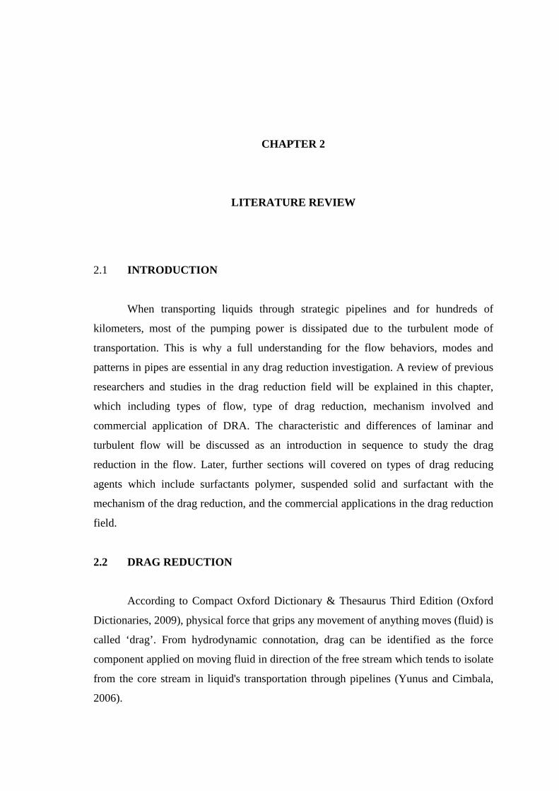
Usually, DRA is injected at the center of pipeline during fully turbulent flow.
DRA works by bursting the buffer zone, increase streaks (laminar sublayer) in pipeline,
decrease vorticity force and increased velocity of flow without supplying extra energy.
Figure 2.1: The effect of CDR (Chemical Drag Reducers) or DRA in pipelines to
reduce pressure drop
Courtesy: King, 2002
Figure 2.1 show the effect of addition the drag reducing agent in the pipeline to
reduce pressure drop. Pressure drop per unit length in the pipeline increases with the
increase of fluid flow rate due to the wall friction and shear force. As the flow begin to
tumble due to shearing, it will create transverse flow in which faster moving particle are
transported into region of lower velocity and vice versa.
Polymers and surfactant micelles are the two main types of homogeneous drag
reduction additives while heterogeneous drag reduction additives include solid phase
fibers or gas phase micro bubbles (Kodama, 2002). These additive help to save the
energy by reducing the recirculation effects (prevent liquids' molecules to rotate) that
existed in turbulent flow. DRA can affect the solvent by changing viscosity. Fluid

elasticity in DRA also hinders the oscillation-induced streaming (Vlassopoulos and
Schowalter, 1994).
Drag reduction has been applied to many flow situations with varying degrees of
success such as hydraulic machinery, flow over submerged bodies, heating systems and
jets (Abdelhamid et al., 2008). The first use of DRA in oil fields was to reduce pressure
loss while pumping fluids down hole into fractured tight formations. Initially, %DR
achieved was 80% in used of 600 ppm by weight in singe phase flow (Vanko, 1997).
(Guisseppina et al., 2011) had studied the influence of the addition of a drag
reducing agent (100ppm PAA) to a pure liquid (water) in a stirred vessel. The vessel
was stirred with two types of agitators, a Rushton turbine and an axial A310 impeller.
This studied had confirmed that the drag-reducing agent decreases power draw and
increases mixing time.
2.3.1 Polymeric DRA
Polymeric DRA is proved to reduce transverse flow gradient, and then
effectively creating flow with less turbulence intensity in the pipe. This phenomenon is
usually occurring close to the pipe wall where axial flow velocity profile has a very
steep gradient in which significant pressure losses happen (Stanford, 2005).
First reported drag reduction by polymeric additive was by Toms in 1946 when
he accidentally discovered during his investigation on polymer mechanical degradation
inside pipe flow apparatus. Dissolving a minute amount of long-chained polymer
molecules in water, the frictional drag of turbulent flow could be reduced dramatically.
The most successful application of drag-reduction phenomenon has been in
reducing the drag in crude oil transport through Trans Alaskan Pipelines (TAPS) and
other pipelines in several countries (Hoyt, 1972). Within 10 years, effectiveness of the
additives has increased up to 12 times from the earlier accomplishment in 1979.
(De Gennes, 1990) stated that polymeric drag reduction is due to elasticity rather
than viscosity nn. However, polymer can be easily degraded and lost their effectiveness
in turbulent flow in short period even it has high molecular weight (>105 ).
(Gadd, 1971) cited polymer additive is the resistance to elongation strain,
resulting shear formation and busting in near wall region which considered modern
conception. (Min and Choi, 2005) also cited the elasticity of polymer is the most
important properties to consider for potential drag reducing agent.
Polymeric DRA interact chemically by binding molecules of polymer and the
solvents. (Massah and Hanratty, 1997) concluded polymer drag reduction could cause
the changing in molecular structures of liquids that tend to produce Reynolds's stress.
The Reynolds shear stress also strongly reduced, especially near the wall, and this is
done by a polymer stress, which at maximum, drag has reduced about 40% of the total
stress. These results have been compared with Laser Doppler Velocimetry (LDV)
experiments (Ptasinski et al., 2001).
Polymers also can act in shelf-sheltering mechanism, which reducing the drag by
decoupling solvent molecules in motions with polymer at the buffer region. (Ptasinski et
al., 2003).

Figure 2.2: Differences between additions of PEO with 42 ppm at two different
times.
A and B: Water without PEO at 0.63second and 0.8 second
C and D: Water with PEO at 0.63 second and 0.8 second
Courtesy: (Janosi et al., 2004)
(Janosi et al., 2004) investigated in dam break flows, where a finite volume of
fluid is released from a compartment into a long, rectangular channel. The result
reported drag reduction occurs in the present of a minute amount of PEO (polyethylene
oxide in different time range. Figure 2.2 shows a picture taken for the PEO drag
reduction behavior and it showed that the flow is much faster in the present of PEO
which one of the polymer chain which has high molecular weight.
Polymers are very effective as DRA but easily degraded due to the mechanical
force from the pumps. The shear force of the pump will degrade the polymer
mechanically (Sellin et al., 1982). The energy that rotating in the pump will break the
linkage of polymer hence reduces its efficiency towards the solvent (Choi et al., 2000).
The efficiency also will be reduced by vorticity stress in the turbulent flows, stressing or
compressing stress in pump.


![arXiv:1902.05577v1 [cs.DC] 14 Feb 2019static.tongtianta.site/paper_pdf/4f88c760-3675-11e9-ae59-00163e08… · Aakash Khochare, Aravindhan K, Yogesh Simmhan ... (DNN) and computer](https://img.pdfslide.us/doc/110x75/5f91826a6f3b4267f33953f1/arxiv190205577v1-csdc-14-feb-aakash-khochare-aravindhan-k-yogesh-simmhan.jpg)


![4255 ts.c.P] 710 E*5+t,— 4120 e 3675 2.5± F FibPBt12. AEP](https://img.pdfslide.us/doc/110x75/6169ffcd11a7b741a34db3ff/4255-tscp-710-e5t-4120-e-3675-25-f-fibpbt12.jpg)