Embed Size (px)
Citation preview

Formula SAE Paddle Shift System
Group Members
Richard Pittman - EEMusab Hmeidan - EE
Sean Feschak – ME/EEKevin Castillo - CpE
12/2/2015 1

Motivation• UCF Formula SAE Team
o Replace mechanical push-pull cable
o Increase competitiveness of team
• Represents a product that could have other useful
applicationso Enable handicapped riders
o Drag-racing motorcycles
o Other forms of amateur and professional racing
• All members interested in project and subsystems
12/2/2015Presenter: Richard 2

Goals• Accessibility and ease of use
• Reliable and highly durable
• Maintainable
• Controllable
• Transferable
• Safe
12/2/2015Presenter: Richard 3

Requirements
12/2/2015Presenter: Richard 4
RequirementID
Requirement Description
EPS. 1 Steering wheel mounted gear display
EPS. 2 Display brightness, 400 nits minimum
EPS. 3 Total system weight, 15 lbs maximum
EPS. 4 Operating temperature range of 20º to 120º F.
EPS. 5 Water Resistant
EPS. 6 Impact Resistant
EPS. 7 GPS tracking
EPS. 8 Data logging with removable SD card
EPS. 9 Complete gear shifting functionality

Realistic Design Constraints
12/2/2015Presenter: Richard 5
• Small Budget from the Formula SAE team
• Must pass all Formula SAE rules and regulations
• Designed around current Formula SAE car
• Must be able to transfer over to future FSAE car

Challenges• Challenged with 5V output of Tiva-C development
boardo Swapped MCU to Arduino UNO
• Challenged with learning how to properly create a schematic on Eagle with no library files for some partso Had to create the .lbr files based upon Cad file dimensions
• Challenged with coding for componentso Group is not familiar with many of the components
• Challenged with Soldering of SMD productso Group is not properly equipped to handle such a task with the equipment
they have
12/2/2015Presenter: Sean 6

Block Diagram
12/2/2015Presenter: Sean 7

Strategic Components
• Shift Componento Low Power Consumption
o Fast Response time
o Reliable
• MCUo Able to control all Inputs
and be able to give the
number of outputs needed
• GPSo Accurate and easy to use for data logging
• Displayo Highly visible
o Small
o Use of few wires
12/2/2015Presenter: Sean 8

Shift Methods
12/2/2015Presenter: Sean 9
Pneumatic shifters
• Requires Tank
• Limited number of shifts
with no Air Compressor
• Air compressor has large power
consumption and weight
Electronic Actuator
• Uses short bursts of power
• Unlimited Shifts
• Does not require other
components to function

Actuator
12/2/2015Presenter: Sean 10
Takes a minimum of 11lbs of force for the lever to shift into gear. o The actuator chosen has 35lbs of force in both the push and pull functions.
The actuator also needs to travel 1 1/8” in both directions for a shift to occur.
o The actuator chosen has a travel of 1 ½” in both directions making it ideal for shifting will not push too far past the required amount adding extra stress on the transmission.

MCU
12/2/2015Presenter: Kevin 11
Arduino Uno (ATmega328P)
Tiva C Launchpad (TM4C123GH6PM)
Primary Features ValuesClock 16 MHzFlash Memory 32 KBSRAM 2 KBOperating Voltage 5VExtended Temperature -40℃ - 85℃
Current Consumption46.5 mA, active1456 µA, sleep
Primary Features ValuesClock 80 MHzFlash Memory 256 KBSRAM 32 KBOperating Voltage 3.3VExtended Temperature -40℃ - 125℃
Current Consumption45 mA, active
1.38 µA, hibernate

GPS
Primary Features ValuesSatellites 22 tracking, 66 searchingSize 16mm x 16mmUpdate Rate 1 to 10 HzPosition Accuracy 3 metersVelocity Accuracy 0.1 meters/sCold Startup Time 34 secondsAcquisition Sensitivity -145 dBmTracking Sensitivity -165 dBmMaximum Velocity 515 m/sVoltage In Range 3.0 – 4.3 VDCOperating Current 25 mA tracking, 20 mA navigationOutput NMEA 0183, 9600 baudOperating Temperature -40 ℃ to 85 ℃
12/2/2015Presenter: Kevin 12
Adafruit Ultimate GPS (MTK 3339)
- Ability to attach a larger antenna to the ANT pad
- Compatible with a majority of Arduino libraries capable of parsing
NMEA 0183 data
- Used TinyGPS for parsing

GPS Imaging• GPS Visualizer: Do-It-Yourself Mapping
• Online utility that creates maps and profiles from GPS data.
• Free and easy to use
• Powerful and extremely customizable.
12/2/2015Presenter: Kevin 13

GPS Testing
Software Test Description Passing Criteria
Rapid ShiftingShift once per second for one minute
All 60 outputs from MCU are correct
Save DataSave data to external storage, with formatting
All data is saved, correct and formatted
GPS Short Distance ReadMove the GPS in 4 meter increments and read location
All coordinates match Google Maps/Earth coordinates with less than 5% error
GPS Rapid Short Distance Read
Move the GPS at approximately 60 mph and read location and speed every 150 milliseconds
All coordinates match Google Maps/Earth coordinates with less than 5% errorAll speeds match actual speeds with less than 5% error
Formula One Track Run
One lap around the track, reading and recording location, speed, shifts and time once per second
All coordinates match Google Maps/Earth coordinates with less than 5% errorAll speeds match actual speeds with less than 5% errorAll shifts match actual shiftsAll times match actual times
12/2/2015Presenter: Kevin 14

Data Logging/ SD Card Slot
12/2/2015Presenter: Kevin 15
Details Description
Power Input 3-5V Onboard 5v->3v regulator
Pin usage 4 Pins Read and write 2Gb+ of storage
LED Activity Yes Lights up when the SD card is being read or
written
Socket Type Push-Push Easy to insert and remove
Mounting Four #2 mounting holes Can be Mounted securely
• Works well with Arduino • Useful resources online• Quick and easy to use

Coding Plan
12/2/2015Presenter: Kevin 16

Driver Controls- Integrated into current steering wheel setup
- Ergonomically designed
- Paddles for upshift and downshift
- Thumb button for neutral
- Conforms to FSAE competition rules
12/2/2015Presenter: Richard 17

Wiring Harness
12/2/2015Presenter: Richard 18
- Essential component of the system
- Must be able to withstand a motorsports environment
- Constructed using mil-spec components
- mil-spec techniques
used during construction

Display Types
12/2/2015Presenter: Sean 19
TFT LCD Display• High cost for High brightness
16 Segment Display• Bright (Visible in direct sunlight)• Cheap
Dot Matrix Display• Many LEDs not needed• Hard to see in direct sunlight
Display
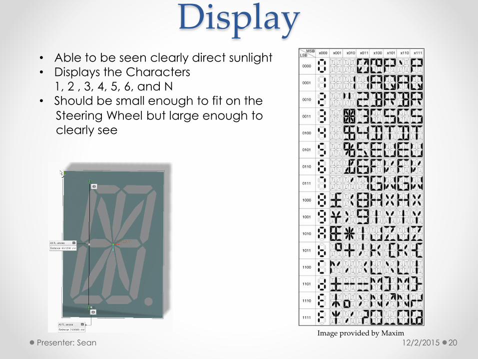
12/2/2015Presenter: Sean 20
• Able to be seen clearly direct sunlight
• Displays the Characters
1, 2 , 3, 4, 5, 6, and N
• Should be small enough to fit on the
Steering Wheel but large enough to
clearly see
Image provided by Maxim

PCB of Main Board
• On board USB to serial converter
• DC jack and power regulator (7-12V input)
• Power regulator (3.3V output)
• ICSP connector
• Serial communication LEDs
12/2/2015Presenter: Sean 21
Removed from Arduino Uno

Display Driver
12/2/2015Presenter: Sean 22
Design Requirements:
• Design the Driver to be the
same size of the Display
• Use less than 4 wires
• Be able to be fully enclosed

Gear Position Sensor• Communicates the gearshift’s position to the
electrical system of the vehicle.
• Assists driver to indicate current gear position.
12/2/2015Presenter: Musab 23

Gear Position Sensor• Come up with a physically similar sensor to be able
to fit it in its original place.
• Certain voltage and resistance values are
associated with each gearshift.
12/2/2015Presenter: Musab 24
Gear Resistance (Ω) Voltage (V)
Neutral open 5
1 570 1.8
2 830 2.26
3 1500 3
4 2700 3.68
5 6800 4.38
6 15000 4.70

Gear Position Sensor• Applied reverse engineering to factory sensor.
• Realized the values of resistance and voltage for gears.
• Used voltage divider to obtain the voltages for each
gear.
12/2/2015Presenter: Musab 25

Gear Position Sensor• Different approach to design.
• Use of hall sensors, magnet, and 7-segment LED
indicator.
• MCU reads signals of the hall sensors and outputs
gear number to the segment through a
counter/decoder.
12/2/2015Presenter: Musab 26

PowerBattery• Battery Family: Lithium Iron Phosphate
• Voltage: 12V
• Capacity: 35Ah
• Charge Rate: 10A
• Weight: 3.75 lbs
• Operating Temp: 40-140°F
12/2/2015Presenter: Musab 27

Power
Component Requirements
12/2/2015Presenter: Musab 28
Component Current (Input) Voltage (Input)
Arduino 50 mA 5 V
Relay 40mA 5 V
SD Card 5mA 3.3-5 V
GPS 30mA 5 V
Display 180mA 5 V
Actuator 4.6A 12 V
Gear Position Sensor
16mA 5 V
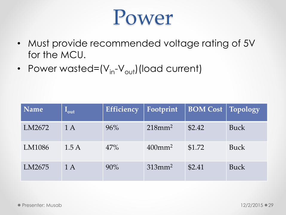
Power• Must provide recommended voltage rating of 5V
for the MCU.
• Power wasted=(Vin-Vout)(load current)
12/2/2015Presenter: Musab 29
Name Iout Efficiency Footprint BOM Cost Topology
LM2672 1 A 96% 218mm2 $2.42 Buck
LM1086 1.5 A 47% 400mm2 $1.72 Buck
LM2675 1 A 90% 313mm2 $2.41 Buck

Power
12/2/2015Presenter: Musab 30
5V switching
regulator
5V linear
regulator
Vo=Vref(1+R2/R1)

SAE TestingFSAE Applicable Formula SAE Competition Rules
T4.6 Accessibility of Controls – All vehicle controls, including the shifter, must be operated from insidethe cockpit without any part of the driver, e.g. hands, arms, or elbows, being outside the planes ofthe side impact structure defined in rule T3.25 and T3.34.
T4.8 Driver Egress – All drivers must be able to exit to the side of the vehicle in no more than 5 seconds.Egress time begins with the driver in the fully seated position, hands in driving position on theconnected steering wheel and wearing the required driver equipment. Egress time will stop whenthe driver has both feet on the pavement.
T6.5.4 The steering wheel must be attached to the column with a quick disconnect. The driver must be ableto operate the quick disconnect while in the normal driving position with gloves on.
T11.2.1 All critical bolts, nuts, and other fasteners on the steering, braking, driver’s harness, and suspensionmust be secured from unintentional loosening by the use of positive locking mechanisms.
T4.1.2 During the template test, the steering wheel, steering column, seat and all padding may be removed.The shifter or shift mechanism may not be removed unless it is integral with the steering wheel andis removed with the steering wheel. The firewall may not be moved or removed.
T4.2.4 Cables, wires, hoses, tubes, etc. must not impede the passage of the templates required by T4.1.1and T4.2.
12/2/2015Presenter: Richard 31

Overall testing
12/2/2015Presenter: Richard 32
- Overall system testing will be carried out in three stages
- Stage one
- Bench test the entire system to ensure it is operating properly
as designed- Stage two
- Initial testing on the Formula SAE car
- Will be conducted with the FSAE car on stands for safety
- Stage three
- Testing to be carried
out jointly between
senior design group
and Formula SAE
team
- To be conducted at
an approved testing
location

Group Dynamics
Richard Sean Musab KevinWiring harness Display Gear position
sensorGPS
Shifting Solenoid/Actuator Neutral Data transmission
Paddles ECU Power distribution Programming
SD card Design Integration Microcontroller
Assisting with GPS
12/2/2015Presenter: Kevin 33
Richard Pittman - Electrical Engineer
SAE Member, knowledgeable in wiring
of vehicles
Sean Feschak - Electrical / Mechanical Engineer
Knowledgeable in both the Mechanical
and Electrical aspects of this project
Musab Hmeidan - Electrical Engineer
Knowledgeable in Power Systems
Kevin Castillo – Computer Engineer
Knowledgeable Computer Programmer

Project Scheduling
12/2/2015Presenter: Kevin 34
Task Name Start EndSenior Design Project Plan 06/02/2015 12/02/2015Meeting to initiate project 06/02/2015 06/02/2015Design flowchart and define roles 06/02/2015 06/04/2015Research microcontrollers 06/04/2015 06/11/2015Research actuators/ solenoids 06/11/2015 06/15/2015Research displays 06/15/2015 06/20/2015Research GPS technologies 06/20/2015 06/23/2015Meeting to summarize research 06/23/2015 06/24/2015Design paper and continue research 06/24/2015 07/01/2015
Meeting to revise paper 07/01/2015 07/02/2015Continue design paper 07/02/2015 07/10/2015Design paddles and 3D print 07/10/2015 07/13/2015Learn EAGLE PCB 07/13/2015 07/16/2015Design wiring harness 07/16/2015 07/20/2015Design upshift and downshift circuit 07/20/2015 07/24/2015
Meeting before rough draft 07/24/2015 07/24/2015Design GPS system 07/24/2015 07/28/2015Finish and edit paper 07/28/2015 08/06/2015Order parts 08/06/2015 08/07/2015Break between semesters 08/07/2015 08/23/2015Begin senior design 2 08/24/2015 08/24/2015Revise ordered parts 08/24/2015 08/25/2015Implement paddles 08/25/2015 09/09/2015Implement gear position sensor/ neutral button 09/09/2015 10/07/2015Design and test Actuator and Solenoid 10/07/2015 10/12/2015Design and test Software 10/12/2015 10/19/2015Design and test GPS/Display 10/19/2015 10/23/2015Design and test Paddles 10/23/2015 10/26/2015Design and test Gear Position Sensor 10/26/2015 10/31/2015Design and test Actuator 10/31/2015 11/05/2015Put system together 11/05/2015 11/10/2015Test final system 11/10/2015 11/20/2015Finish documents 11/20/2015 12/02/2015Present project 12/02/2015 12/02/2015

BudgetPart Unit
PriceQuantity Funded Total Cost
To GroupDescription
Display $40 1 $40 Purchased
Wiring $180 1 SAE $0 Purchased
PCB Manufacturing $40 1 $40 Purchased
Breadboard $10 1 $10 Purchased
GPS Unit $50.68 1 $50.68 Purchased
Microcontroller (exact TBA)
$20 3 $60 Purchased
Voltage Regulator $10 3 $30 Purchased
Paddle $25 2 $50 Purchased
Actuator $300 1 SAE $0 Purchased
Micro SD $20 1 $20 Purchased
Battery Free 1 $0 Already Installed
Micro switch $5.86 2 $11.72 Purchased
Gear sensor $20 1 $20 Purchased
Receiver $35 1 $35 Purchased
Tool Box (Sockets, Bearings, Screws,
etc.)
$20 1 SAE $0 Purchased
Transistor $2 3 $6 Purchased
Total Cost $500 $373.4
12/2/2015Presenter: Richard 35

Current Status
12/2/2015Presenter: Richard 36
90
100
90
100
100
100
100
100
0 10 20 30 40 50 60 70 80 90 100
PROGRAMMING
GPS MODULE
DISPLAY
ACTUATOR CONTROLLER
POWER
INTEGRATION
RESEARCH
PROTOTYPE
Subsystem Completion Status

Questions
12/2/2015 37