Embed Size (px)
Citation preview


BACKGROUND CHECKS Consumer Report Disclosure & Release List of Residence Form
COMPANY VEHICLES & MOBILE EQUIPMENT Vehicle Accident Forms Vehicle Inspection Card Vehicle Transfer Form Aerial Lift or Scissor Lift Inspection Checklist ATV Inspection Checklist Bucket Truck Inspection Checklist Crane: Monthly Inspection Form Crane: JSA Crane: Hand Signals Chart Ditch Witch Inspection Checklist Forklift Inspection Checklist
EMPLOYEE INJURY or ILLNESS Near-Miss Report Injury Reporting Procedures Employee's Report of Injury Supervisor's Accident Investigation Form Return to Work Policy Statement Return to Work Evaluation Form Letter to Doctor
ELECTRICAL Electric Tool & Cord Color Chart Electric Tool Inspection Record Lockout-Tagout Checklist
ENERGIZED WORK FORMS Customer or Client Communication Form Task Assessment ChecklistMethod of Procedure Energized Work Permit Job Safety Briefing Form Approach Boundaries Table (AC Only) Approach Boundaries Table (DC Only) Arc Flash Hazard Identification Table Arc Flash PPE Categories (AC Only) Arc Flash PPE Categories (DC Only) EWP Flow Charts Checklist for Arc Flash Assessments Energized Work Protective Clothing Table
ENERGIZED WORK PROGRAM INFORMATION

10 Things to Know About Arc Flash Design & Integration Needs & Benefits of Policy
ENVIRONMENTAL Environmental Release & Corrective Actions Form Oil Spill & Chemical Release Form Heat Index Chart How to Treat a Heat Emergency Hydration Chart
RESPIRATOR Medical Questionnaire Form Respirator Fit Test Form
SAFETY INSPECTIONS & INVESTIGATIONS Weekly Safety Inspection Checklist (PDF) Weekly Safety Inspection Checklist (Excel) In Depth Safety Inspection Report Incident Investigation (multiple uses) Accident Investigation Report Underground Line-Cable Damage Report
MISCELLANEOUS CHECKLISTS & FORMS Bomb Threat Checklist Confined Spaces Permit CROSBY CLAMPS EEO Federal Project Checklist Emergency-Contingency Plan Checklist Ergonomic Checklist Excavation Inspection Checklist Fall Protection Checklist Hot-Work Permit (not electrical) IMPACT Safety Card Job Safety Analysis (JSA) JSA/JHA Form (with examples [Excel]) Ladder Inspection Form Pre-Task Checklist Pre-Task Checklist (fillable form) Project Start-Up Checklist (Excel) Rope Inspection Guideline Scaffolding Inspection Checklist Site Specific Safety Plan (boilerplate [Word]) Summer Helper Acknowledgement Form
Consumer Report Disclosure & Release
CONSUMER REPORT DISCLOSURE & RELEASE (EMPLOYMENT)
DISCLOSURE
In connection with your employment or application for employment (including contract for services), consumer reports may be requested from HireRight or Employment Background Investigations (“EBI”). These reports may include the following types of information: names and dates of previous employers, reason for termination of employment, work experience, accidents, academic history, professional credentials, and drugs/alcohol use. Such reports may contain public record information concerning your driving record, criminal records, etc., from federal, state and other agencies which maintain such records; as well as information from HireRight or EBI concerning previous driving record requests made by others from such state agencies and state provided driving records.
You have the right to make a request to HireRight or EBI, upon proper identification, to request the nature and substance of all information in its files on you at the time of your request, including the sources of information and the recipients of any reports on you that HireRight or EBI has previously furnished within the two-year period preceding your request.
RELEASE
I AUTHORIZE, WITHOUT RESERVATION, HIRERIGHT OR EBI AND ANY PARTY OR AGENCY CONTACTED BY USIS OR EBI, TO FURNISH THE ABOVE-MENTIONED INFORMATION.
HireRight or EBI is authorized to disclose all information obtained to the requesting entity for the purpose of making a determination as to my eligibility for employment, promotion or any other lawful purpose. I agree that such information which HireRight or EBI has or obtains, and my employment history if I am hired, may be supplied by HireRight or EBI to other companies that subscribe to HireRight or EBI. If hired or contracted, this authorization shall remain on file and shall serve as ongoing authorization for the procurement of consumer reports at any time during my employment or contract period.
By signing below, I certify that I have read and fully understand this release, that prior to signing I was given an opportunity to ask questions and to have those questions answered to my satisfaction, and that I executed this release voluntarily and with the knowledge that the information being released could affect my being hired, my employment, or my eligibility for promotion.
Print Applicant Name Applicant Signature
Social Security Number Date
___________________________________________ ____________ _______________ Date of Birth Sex Race
List of Residence Form
CONSUMER REPORT DISCLOSURE & RELEASE (EMPLOYMENT)
List of Residences
List all residences for last 7 years; Name
Street Apt.
City County State
Street Apt.
City County State
Street Apt.
City County State
Street Apt.
City County State
Street Apt.
City County State

Vehicle Accident Forms
MOTOR VEHICLE ACCIDENT FORM
IF YOU ARE INVOLVED IN AN ACCIDENT
1. Stop at Once! Check for personal injuries and send for an ambulance, if
needed. Do not leave the scene, but ask for the assistance of bystanders.
2. If Fire or Smoke Is Present, evacuate vehicle occupants to a safe location.
If stalled on a railroad track, evacuate occupants to a safe location away and
at a right angle from the tracks.
3. If Fire, Smoke or Spilled Fuel is Present, send for the fire department. Do
not leave the scene; ask a bystander to call the fire department. If possible,
use a spill kit to absorb the spill.
4. Protect the Scene. Set emergency warning devices to prevent further
injury or damage. Secure your vehicle and its contents from theft.
5. Secure Assistance of the police whenever possible. Record names and
badge numbers.
6. Record Names, Addresses and Phone Numbers of all witnesses, injured
and driver(s) and their passengers. Record vehicle license numbers.
7. Do Not Argue! Make no statement except to the proper authorities. Sign
only official police reports. Do not make statements regarding the operating
condition of your vehicle and do not admit fault.
8. Report the Incident to Your Supervisor IMMEDIATELY after first aid
has been given, authorities have been notified, the scene has been protected
and you are able to do so.

9. Complete the Incident Report at the scene as thoroughly as possible.
Exchange insurance information only with other involved driver(s).
10. If You Strike An Unattended Vehicle and cannot locate the owner, leave
a note with your name and the company's address and phone number, get the
vehicle description, VIN number and license plate number.
11. Contact the Safety Department as soon as possible (904) 981-0205. Turn
in a copy of the accident report, pictures, and a written statement of the
incident.
MOTOR VEHICLE ACCIDENT FORM
INJURIES – Describe nature of any apparent injuries:
Driver: Other Passenger,
Pedestrian
Injury___________________________________ Name:
______________________________
Passenger: Address:
_____________________________
Name: __________________________________ Injury:
_______________________________
Injury: _________________________________ Name:
_______________________________
Other Driver: Address:
_____________________________
Name: ____________________________________ Injury:
_____________________________
Address: __________________________________ Where taken after
accident ____________

Injury: ____________________________________
_________________________________
POLICE PFFICER ASSISTING
Name: _____________________________________ Police report made?
Yes No
Headquarters: ______________Badge No. ________ Citations Issued:
___________________
Property damage – Describe nature of damage:
Your Vehicle: ______________________________ Other Vehicle:
____________________
_________________________________________
________________________________
Property other than Vehicles _________________ Owner
____________Phone ( ) ______
________________________________________ Driver
____________Phone ( ) ______
__________________________________________ Vehicle
Make______ License No. ____
Owner_______________________ Phone ( ) ________ Insurance
Company ______________
WITNESSES
Name: _____________ Phone ( ) __________ Name:
_______________ Phone ( ) _______
Address: ______________________________ Address:
____________________________
Name: _____________ Phone ( ) __________ Name:
_______________ Phone ( ) _______
Address: ______________________________ Address:
____________________________

“ON THE SPOT”
ACCIDENT REPORT
My Name ____________________________ Age ________
Driver’s License _________________________State ________________
Employee No. ____________________________________
My Vehicle __________________________
(Year) ____________________ (Make) __________________
(Unit No) _______________ (License No) _______________
(State) _______________
(Unit No) _______________ (License No) _______________
(State) _______________
ACCIDENT SKETCH
Draw an accident sketch. Show and label roadway, indicate number of lanes, direction of travel
and signs. Number each vehicle and show direction of travel from point hazard was noticed to
point of impact by a solid line and any travel after impact by a dotted line.
Indicate direction____
At what distance did you notice danger?
_________feet
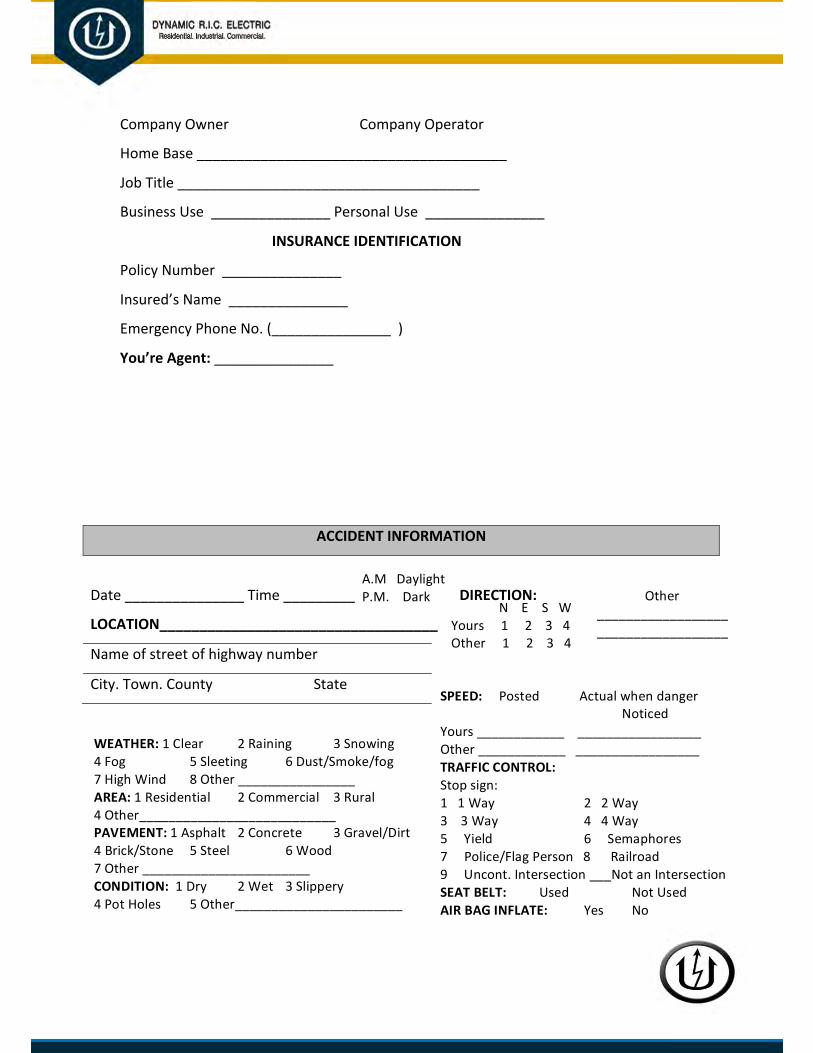
Company Owner Company Operator
Home Base _______________________________________
Job Title ______________________________________
Business Use _______________ Personal Use _______________
INSURANCE IDENTIFICATION
Policy Number _______________
Insured’s Name _______________
Emergency Phone No. (_______________ )
You’re Agent: _______________
ACCIDENT INFORMATION
Date _______________ Time _________ DIRECTION:
LOCATION___________________________________
Name of street of highway number
City. Town. County State
A.M DaylightP.M. Dark
N E S W Yours 1 2 3 4 Other 1 2 3 4
Other ____________________________________
SPEED: Posted Actual when danger Noticed
Yours ____________ _________________ Other ____________ _________________ TRAFFIC CONTROL: Stop sign: 1 1 Way 2 2 Way 3 3 Way 4 4 Way 5 Yield 6 Semaphores 7 Police/Flag Person 8 Railroad 9 Uncont. Intersection ___Not an Intersection SEAT BELT: Used Not Used AIR BAG INFLATE: Yes No
WEATHER: 1 Clear 2 Raining 3 Snowing 4 Fog 5 Sleeting 6 Dust/Smoke/fog 7 High Wind 8 Other ________________ AREA: 1 Residential 2 Commercial 3 Rural 4 Other___________________________ PAVEMENT: 1 Asphalt 2 Concrete 3 Gravel/Dirt 4 Brick/Stone 5 Steel 6 Wood 7 Other _______________________ CONDITION: 1 Dry 2 Wet 3 Slippery 4 Pot Holes 5 Other_______________________

ACCIDENT DESCRIPTION
Briefly tell how the accident happed. Indicate of involved vehicles when hazard was first noticed,
warning or evasive action taken and length and position of any skid marks.

Vehicle Inspection Card
ITEMS TO BE CHECKED 1 CLEANLINESS/DAMAGE/MISSING ITEMS (Interior/Exterior) 2 UNUSUAL NOISE OR OCCURRENCE (During Operation) 3 LEAKS/FLUID LEVELS (Visually check for any leaks/check oil,coolant,hydr,trans,brake) 4 SAFETY DEVICES (Wiring/lights/horn/warning devices/reflectors/mirrors/seat belts) 5 BATTERIES (Fluid/damage/cleanliness/security) 6 INSTRUMENTS/GAUGES (Operation & readings) 7 DRIVE BELTS (Fraying/cracking/tension) 8 PULLY/MOTOR (Air/hydraulic/electrical) 9 STEERING/SPRINGS/SHACKLES (Free play/excessive wear)
10 EXHAUST SYSTEM (Damage/leaks) 11 TIRES/WHEELS (Lug nuts/cracks) TRACKS 12 HEATER/DEFROSTER/AIR-CONDITIONER 13 BRAKES (Servicing-Parking) / CLUTCHES (Operate) / ACCELERATOR PEDAL (Damage/worn) 14 WINDSHIELD (Wipers/washer fluid/cracks) 15 POWER TAKE-OFF (PTO) 16 WINCH/TOW CONNECTIONS 17 AIR TANKS (Drain daily or after operation) 18 MARKINGS-CHECK LEGIBILITY 19 BOOMS/OUTRIGGERS/BASKET/PLATFORM (Check for cracks and damage) 20 HOISTING MECHANISM 21 OTHER (Specify) 22 OTHER (Specify) 23 OTHER (Specify) 24 OTHER (Specify) 25 OTHER (Specify)

OPERATOR'S INSPECTION GUIDE AND TROUBLE REPORT MONTH/YEAR
TRUCK NUMBER TYPE OF VEHICLE/EQUIPMENT
PROJECT MANAGER LOCATION PHONE NO.
FLEET MANAGER NAME PHONE NO.
OPERATOR'S SIGNATURE SIGNIFIES ACCOMPLISHMENT OF CHECKS (LAST NAME ONLY REQUIRED)
DAY SIGNATURE DAY SIGNATURE DAY SIGNATURE 1 11 21
2 12 22
3 13 23
4 14 24
5 15 25
6 16 26
7 17 27
8 18 28
9 19 29
10 20 30
31

Vehicle Transfer Form
VEHICLE TRANSFER FORM
Pleasecompletethisformforanyofthefollowing: 1. Personnelchange(addition,removalorswitch)foravehicle
2. Relocationofavehicle(suchastoadifferentbranchofficeorlongtermproject)
3. ChangeofProjectManagerassociatedforthedriverofavehicle
EFFECTIVE DATE:
TRUCK NUMBER: ODOMETER:
HOURS (if applicable): ANY MAINTENANCE CONCERNS:
NEW DRIVER:
FORMER DRIVER:
STATUS OF FORMER DRIVER: (removed,changedvehicle,retired,nolongeremployed,etc.)
PROJECT MANAGER ASSIGNED:
DIVISION OR LOCATION OF VEHICLE: Please select from list
SUBMIT
OPERATOR'S MONTHLY REQUIREMENT BEGINNING OF MONTH OPERATING MILES/HOURS TIRE PRESSURE CHECK
MILES: DATE: HOURS: FRONT: LBS REAR: LBS
OPERATOR'S NAME (print legibly) OPERATOR'S SIGNATURE DATE:
VEHICLE / EQUIPMENT DISCREPANCY AND MAINTENANCE REPORT
OPERATOR REPORT REPORTED TO MAINTENANCE STATUS ITEM NO. DISCREPANCY DATE
DISC.DATE/ TIME
MILES/ HOURS NAME (print legibly) DATE STATUS
CODE INIT.
STATUS CODE
C + CORRECTED
C-T by Temp Fix D-P for Parts W + Waiver for Repair
D + DELAYED D-M for Maint
C-P by Temp Fix D-D for Disposition N = No Repair

Division and Location Codes: AssignedtoaBranch Divisions(notassignedtoabranch)Atlanta Commercial Birmingham Corporate Services Charlotte Healthcare Irving Industrial Lakeland Jax Service Dept. Little Rock Transportation Richmond South Florida

Aerial Lift or Scissor Lift Inspection Checklist
Project Safety, Hazard Communication and Substance Abuse Manual
Revision No. 1 Date Revised: 8/2011 Doc Number: Appendix 3842 Date Issued: Supersedes all others Aerial/Scissor Lift Pre-Operation Checklist Please Print
OPERATOR: TYPE/MODEL #:
INSPECTED BY: DATE/TIME:
Inspection Item Pass Fail Comments The manufacturer’s operations manual is stored on Aerial or Scissor
P F Lift.
Safety decals are in place and readable. P F
Control panel is clean & all buttons/switches are clearly visible (no
P F paint over spray, etc.)
All safety indicator lights work. P F
Motion alarms are functional. P F
All guardrails are sound and in place, including basket chains, and
P F gate door.
All switch & mechanical guards are in good condition and properly
P F installed.
Work platform extension slides in and out freely with safety locking
P F pins in place to lock setting on models with extension platforms.
Work platform & extension slides are clean, dry, & clear of debris. P F

Inspect for defects such as cracked welds, fuel leaks, hydraulic
P F leaks, damaged control cables or wire harness, etc.
Operating and emergency controls are in proper working condition,
P F EMO button or Emergency Stop.
Both upper and lower controls are adequately protected from
P F inadvertent operation.
Drive controls function properly & are accurately labeled (up, down,
P F right, left, forward, back).
Emergency lowering function operates properly. P F
Lower operating controls successfully over ride the upper controls. P F
Upper drive controls interlock mechanism is functional (i.e. foot
P F pedal, spring lock, or two hand controls).
Tires and wheels are in good condition, with adequate air pressure
P F if pneumatic.
Braking devices are operating properly. P F
Inspect the battery and hydraulic equipment. P F
Grounding Strap is in place and operational. P F
Explain any item marked "F" (fail):

Workplace Assessment: Survey work area for potential hazardous operating conditions prior to aerial/scissor lift usage. Ensure hazards identified are addressed in the JSA or pre-task planning process with sufficient strategies to mitigate the hazards or risks. Floor/ground conditions: Drop offs, holes, uneven surfaces, sloped floors, unstable ground,
¨ Present ¨ Not present etc. Housekeeping: Debris, floor obstructions, cords, construction materials, supplies, etc. ¨ Present ¨ Not present Hazardous Energy: Electrical power cables or panels, chemical/gas/drain lines, utilities, etc. ¨ Present ¨ Not present Overhead obstructions: Tight working conditions, adjacentstructures, pipe racks, beams, ¨ Present ¨ Not present ceiling grids, etc.

ATV Inspection Checklist
ATV / UTV PRE-INSPECTION CHECKLIST
EQUIPMENT NUMBER: ________________ INSPECTED BY: _________________________
DATE: ________________ PROJECT #:
_________________________

Bucket Truck Inspection Checklist
Aerial Platform Truck Daily Inspection Report
Articulating Aerial Boom Truck -
Operator’s Last Name__________________________ Date of Inspection____________
This Inspection Report must be completed (if any problem is noted) before or after work task has been completed.
1. Evidence Of Leaks§ Oil, Hydraulic and/or other Fluids Y N
_______________________________________
2. Broken, damaged, loose or missing parts Y N _______________________________________
3. Tire Abnormalities (bulges, cuts, wear, or low pressure) Y N _______________________________________
4. Operator and Safety Manual in Place Y N _______________________________________
5. Decals/Stickers on boom, platform, bucket Y N _______________________________________
1. Are they in place and legible
6. Welds (are the boom/bucket welds in good condition) Y N _______________________________________
7. Working lights (Headlights, Directional and Strobes) Y N _______________________________________
ü If the following items present: Location q Chock Blocks (2) Both sides or rear step
q Fire extinguisher (ABC) 101b. – Properly Charged Front Compartment -Passenger side
q Traffic Cones (4) Back Step – Driver Side
q First Aid Kit Front Compartment -Passenger side
q Full Body Harness Front Compartment -Passenger side
q Lanyard (£ 2’) Front Compartment -Passenger side
Utility Body ü If each of the following if they are in proper working order q Back up lights and alarms q Bucket q Deadman control

q Emergency controls q Fall protection device and lanyard q Ground controls q Guards q Platform door latch
q Upper and lower boom latches
Vehicle Cab General Notes ü If each of the following are in proper working order q Brakes
___________________________________________ q Steering
___________________________________________ q Directional
___________________________________________ q Wipers
___________________________________________ q Heater/Defrost
___________________________________________ q Interior Lights
___________________________________________ q Battery
___________________________________________ q Fluids
___________________________________________
Additional Notes: ___________________________________________________________________ ___________________________________________________________________ _________________________________________________________________________________________________
Identify all known or potential areas of concern on this inspection form and report it to the Fleet Maintenance personnel The “operator” shall take the vehicle out-of-service for safety hazards and leaks utilizing the Dynamic R.I.C. Electric “Caution Tags”
The vehicle can not be used or placed back into service until… a. Vehicle Maintenance Supervisor has indicated that the vehicle is safe to use, orb. The vehicle has been completely repaired, and the “Caution Tag” removed bythe Fleet Maintenance.

Crane: Monthly Inspection Form
Crane Inspection Form
Shift and Monthly Inspection by a Competent Person
29 CFR 1926.1412 and 29 CFR 1926.1413
CRANE: ___________________________________ DATE: _______________________________
INSPECTOR: ________________________ SIGNATURE: _______________________________
Check the box next to each item after it has passed inspection. Note any deficiencies or other observations that could pose a risk of injury or property damage. Equipment must not be used until all corrective action is taken. Keep this document for 3 months if using for monthly inspections.
Item or Function Inspected Deficiencies Found Corrective Action Taken
Ground conditions around the equipment for proper support, including ground settling under and around outriggers/stabilizers and supporting foundations, groundwater accumulation, or similar conditions
Control mechanisms for maladjustments interfering with proper operation
Control and drive mechanisms for apparent excessive wear of components and contamination by lubricants, water, or other foreign matter
Air, hydraulic, and other pressurized lines for deterioration or leakage, particularly those that flex in normal operation
Hydraulic system for proper fluid level

Hooks and latches for deformation, cracks, excessive wear, or damage such as from chemicals or heat
Wire rope reeving for compliance with the manufacturer's specifications
Electrical apparatus for malfunctioning, signs of apparent excessive deterioration, dirt, or moisture accumulation
Tires (when in use) for proper inflation and condition
The equipment for level position within the tolerances specified by the equipment manufacturer's recommendations, both before each shift and after each move and setup
Operator cab windows for significant cracks, breaks, or other deficiencies that would hamper the operator's view
Rails, rail stops, rail clamps, and supporting surfaces when the equipment has rail traveling
Safety devices and operational aids for proper operation
Note: Where a wire rope is required to be removed from service, either the equipment (as a whole) or the hoist with that wire rope must be tagged-out until the wire rope is repaired or replaced.

Wire Rope Category I
If a deficiency constitutes a safety hazard, do not use until replaced. If the deficiency is localized and the problem is corrected by severing the wire rope in two, the undamaged portion may be used. Joining lengths of wire rope by splicing is prohibited. If a rope is shortened, the drum must still have two wraps of wire when the load and/or boom are in the lowest position.
Significant distortion of the wire rope structure such as kinking, crushing, unstranding, birdcaging, signs of core failure, or steel core protrusion between the outer strands
Significant corrosion
Electric arc damage (from a source other than power lines) or heat damage
Improperly applied end connections
Significantly corroded, cracked, bent, or worn end connections (such as from severe service)
Wire Rope Category II
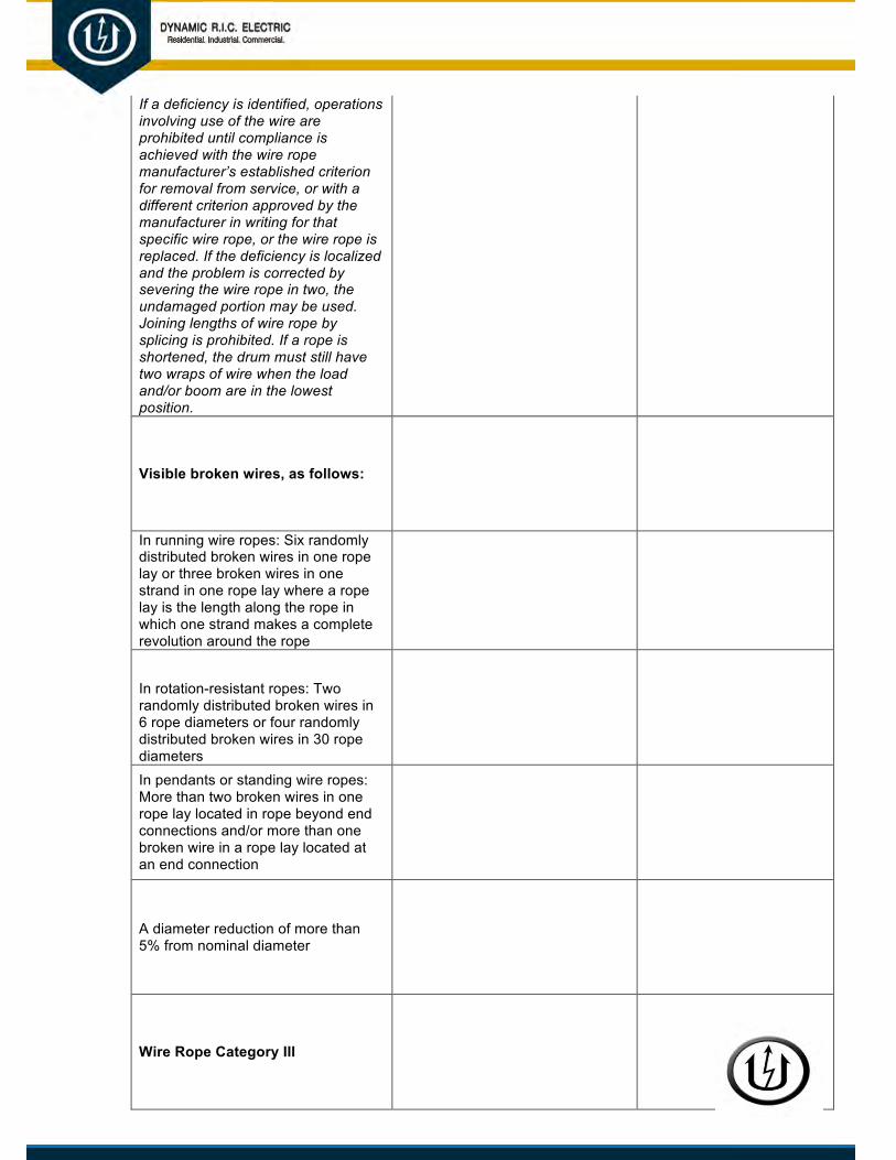
If a deficiency is identified, operations involving use of the wire are prohibited until compliance is achieved with the wire rope manufacturer’s established criterion for removal from service, or with a different criterion approved by the manufacturer in writing for that specific wire rope, or the wire rope is replaced. If the deficiency is localized and the problem is corrected by severing the wire rope in two, the undamaged portion may be used. Joining lengths of wire rope by splicing is prohibited. If a rope is shortened, the drum must still have two wraps of wire when the load and/or boom are in the lowest position.
Visible broken wires, as follows:
In running wire ropes: Six randomly distributed broken wires in one rope lay or three broken wires in one strand in one rope lay where a rope lay is the length along the rope in which one strand makes a complete revolution around the rope
In rotation-resistant ropes: Two randomly distributed broken wires in 6 rope diameters or four randomly distributed broken wires in 30 rope diameters
In pendants or standing wire ropes: More than two broken wires in one rope lay located in rope beyond end connections and/or more than one broken wire in a rope lay located at an end connection
A diameter reduction of more than 5% from nominal diameter
Wire Rope Category III

If a deficiency is identified, operations involving use of the wire rope in question are prohibited until the wire rope is replaced, or if the deficiency (other than power line contact) is localized and the problem is corrected by severing the wire rope in two, the undamaged portion may continue to be used. Joining lengths of wire rope by splicing is prohibited. Repair of wire rope that contacted an energized power line is also prohibited. If a rope is shortened, the drum must still have two wraps of wire when the load and/or boom are in the lowest position.
In rotation-resistant wire rope, core protrusion, or other distortion indicating core failure
Prior electrical contact with a power line
A broken strand
Wire Rope Critical Review Items
Give particular attention to the following:
Rotation-resistant wire rope in use

Wire rope being used for boom hoists and luffing hoists, particularly at reverse bends
Wire rope at flange points, crossover points, and repetitive pickup points on drums
Wire rope at or near terminal ends
Wire rope in contact with saddles, equalizer sheaves, or other sheaves where rope travel is limited
Deficiencies found during the annual inspection that require monitoring:

Crane: JSA
JOB SAFETY ANALYSIS
Safety Information for Dynamic R.I.C. Electric Company
TASK: CRANE OPERATIONS
TASK HAZARDS CONTROLS
Training Requirements: Personal Protective Equipment (PPE) Requirements:
By signing below, I certify that I have been briefed on the operations that are to take place. All hazards have been identified and control measures have been discussed and/or implemented to ensure my safety. I further acknowledge that I will not deviate from the designed plan as an additional measure of not only my own safety, but the safety of those who are around me.
PRINT NAME SIGN NAME

Supervisor’s Printed Name: ____________________________________
Date: ___________________________
Supervisor’s Signature: _______________________________________

Crane: Hand Signals Chart
STANDARD HAND SIGNALS FOR CRANE OPERATION
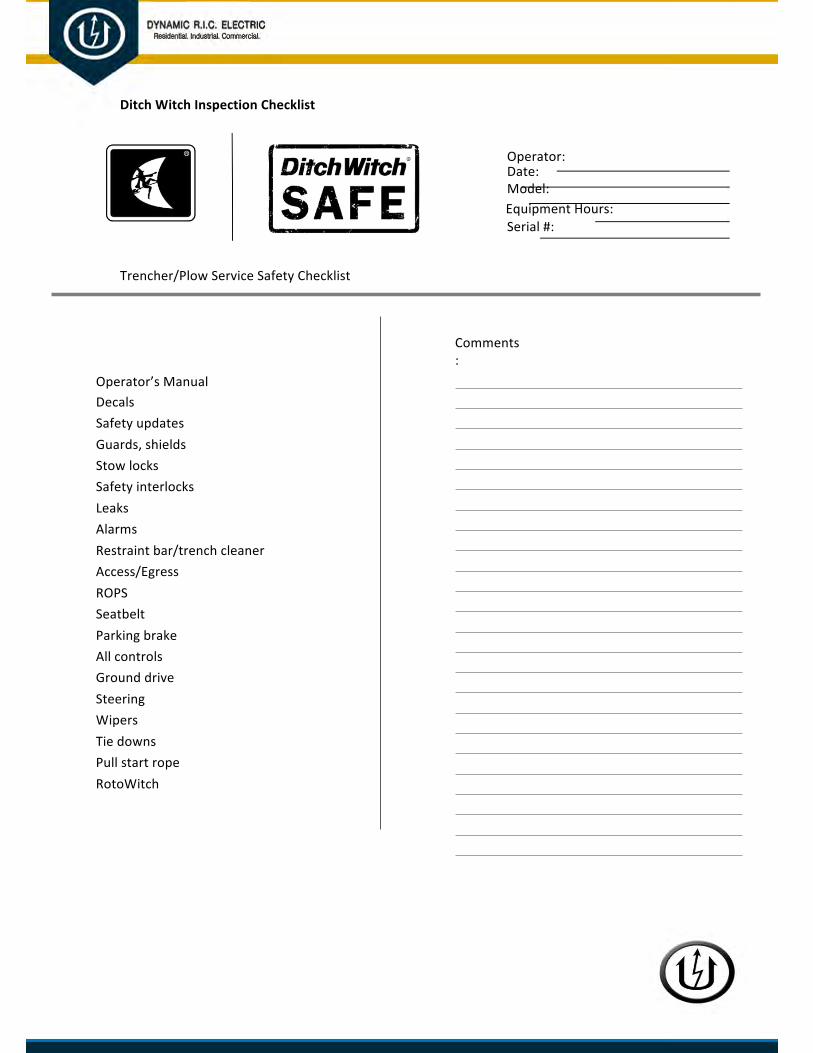
Ditch Witch Inspection Checklist
Operator: Date: Model: Equipment Hours: Serial #:
Trencher/Plow Service Safety Checklist
Operator’s Manual Decals Safety updates Guards, shields Stow locks Safety interlocks Leaks Alarms Restraint bar/trench cleaner Access/Egress ROPS Seatbelt Parking brake All controls Ground drive Steering Wipers Tie downs Pull start rope RotoWitch
Comments:

Thecompletionofthisinspectionandanycorrectionsdonotguaranteesafeoperationofthemachine.Theoperatormuststilluseproperoperatingproceduresandgoodjudgment,includingstoppingoperationifanythingdoesnotlook,feelorsoundnormal.
Operator’s Manual Present – Manualisonthemachine.Condition – Acceptableincondition(legible).
Decals Present – Decalsarepresentandcorrectperthepartsmanual.Condition – Decalsarelegibleandsecurelyattachedsothatlegibilitywillnotbejeopardized.
Safety updates Complete – Allrequiredsafetyupdatesforthismodelhavebeenperformed.Contactdealership,ifunknown.
Guards, shields Present – Guardsandshieldsareinplaceperthepartsmanual.Condition – Guardsandshieldsareingoodcondition.Fasteners – Allfastenersarepresent.
Stow locks Present – Stowlocksareinplaceperthepartsmanual.Condition – Stowlocksfunctionandshownosignsofdamage.
Safety interlocks Start Interlock – Allsafetyinterlocksfunctionproperly.Machinecannotstartunlessinterlockrequirementsaremet.Operator Presence –- Seatswitchorotheroperatorpresenceswitchisinplaceandfunctioningproperly.
Leaks Novisibleleaksofanykind.Nooilorfuelonflooraftermachineisstationary.
Alarms, if equipped Backup alarm,ifequipped,soundswhenmachineisinreverse.Parking brake alarm,ifequipped,soundswhengrounddriveandparkingbrakearebothengaged.
Restraint bar/trench Present – Arestraintbarortrenchcleanerisinplace.Ifequippedwithatrenchcleaner cleaner,trenchcleanershoeisinplace.
Fasteners – Fasteners/hardwareareallpresentandtight.
Access/Egress Steps, handholds, handrails, catwalks areinstalledproperlyandundamaged.Non-skid surface isingoodcondition.
ROPS (all seated, ride-on Damage – Nocracks,dents,deformation,rust,oranyotherdamage. machines) Modifications – Originalmanufacturer’s ROPSisinplaceandnothinghasbeen
addedtoROPS(noheavyobjectshanging,welding,cutsorholesdrilled)Fasteners – Fastenersareproperlytightened.Attachments – TractorweightwithattachmentsdoesnotexceedROPSrating(seeROPScertificationtaglocatedonROPS).Sometractor/attachmentcombinationsrequireheavydutyROPS.

Seatbelt (all seated, ride- Seat belt webbing isfreeofcuts,fraying,extremeorunusualwear.Checktheon machines) buckle/latchareaandanyplacewheretheseatbelthascontactwiththe
equipmentorseat.Buckle operatesproperly.Wheninsertingthelatch,anaudibleclickisheard.Thebuckleisnotdamaged,crackedorbroken.Retractor operatesproperly.Whenpulledandreleasedslowly,seatbeltspoolsoutandretractswithoutlocking.Latch operatesproperly.Wheninsertedintobuckle,latchinsertssmoothlyandanaudibleclickisheard.Latchdoesnotreleasewhentuggingonseatbelt.Latchisnotworn,deformedorcorroded.Mounting hardware(bolts)onbothsidesofseataretightandarenotmissing,rusted,corrodedordamaged.
Parking brake, if equipped Components – Nodamagedorbindingcomponents.Cables – Nodamage,binding,kinking,etc.Pads – Acceptablewear.Pin/sprocket – Engages/disengagesproperly.Holding – Parkona20%(approximately12o)slopefacinguphill,engageparkbrake,putmachineinneutral,machineshouldnotmovewithenginerunningorshut-off–repeattestfacingdownhill.
All controls Function – Allcontrolsfunctionproperlypertheoperator’smanual.Return to neutral – Hold-to-runcontrolsreturntoneutralwhenhandleisreleased.
Ground drive Responsive – Grounddriveisresponsivetocontrolsinbothdirections.Return to neutral – Whengrounddriveisinneutral,themachinecreepiswithinanacceptablerange.Veryslightmachinecreep(maximum6ft/min(1.8
m/min)ona14oslope)isacceptableifitcanbestoppedbybackthrottlingthehydrostaticcontrolsoriftheparkingbrakecanbeapplied.Stopping – Whengrounddriveisdisengaged,machinestopsinanacceptablerange.
Steering Responsive – Steeringisresponsiveandcontrollable.Wipers (cab units) Function – Wipersfunctionproperly.
Condition – Wipersareinacceptablecondition.
Tie downs Condition – Alltiedownsshownosignsofdamage,deformation,orcracks.
Pull start rope, if equipped Recoil – Roperecoilsproperly.Condition – Ropeisnotfrayedorcut.Handleisnotbrokenorcracked.
RotoWitch, if equipped Condition – YokeguardisinstalledonRotoWitch,ifapplicable.Decalsarepresentandlegible.Mountingistightandsturdy.Controls – ControlsforRotoWitchfunctionproperlyinbothdirections.TheRotoWitchrotationstopswhencontrolisreleased.

Forklift Inspection Checklist
Forklift Pre-Operation Inspection Checklist

EMPLOYEE INJURY or ILLNESS
Near-Miss Report
Near-Miss Incident Report
Please complete and submit this form within 24 hours of the incident.
Date: _________________________________________________________________________
Date of incident: _________________________ Time of incident: _____________ AM / PM Exact location:
_________________________________________________________________
Submitted by: _____________________________ Job Number:_________________________
Job activity at the time of the near-miss:
______________________________________________________________________________
______________________________________________________________________________
Description of the near-miss incident (attach photos or diagrams if available):
______________________________________________________________________________
______________________________________________________________________________
______________________________________________________________________________
Specify the hazardous condition:
______________________________________________________________________________
______________________________________________________________________________
Specify the unsafe act:
______________________________________________________________________________
______________________________________________________________________________
Other employees involved, if any:
______________________________________________________________________________
Preventive action recommended:
______________________________________________________________________________
Date and type of corrective actions taken:
______________________________________________________________________________
Supervisor responsible: __________________________________________________________

Employee's Report of Injury
This form must be completed in detail and signed by the injured employee.
Your Full Name Project Number/Name
Social Security Number City Loc. # Dept. #
Your Address (Street, City, State, Zip) Supervisor's Name
Phone Number Where You Can be Reached Job Title at Time of Injury
Date of Hire How Long in Current Position
Yrs. Mos.
Details of the Injury
Date of Injury Time of Injury Weather
AM / PM
Where in the workplace did your injury occur?
How did your injury happen? Describe in detail.
What safety equipment was provided to you at the time of the accident?

Was the cause of your injury due to human or machine error?
Machine Error Human
In your opinion, what was the cause of your injury?
What safety measures do you think can be taken to prevent an injury of this type in the future?
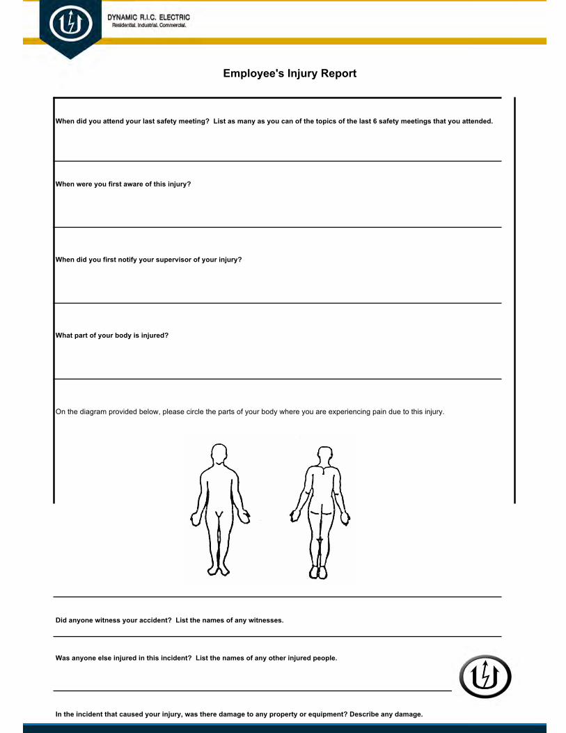
Employee's Injury Report
When did you attend your last safety meeting? List as many as you can of the topics of the last 6 safety meetings that you attended.
When were you first aware of this injury?
When did you first notify your supervisor of your injury?
What part of your body is injured?
On the diagram provided below, please circle the parts of your body where you are experiencing pain due to this injury.
Did anyone witness your accident? List the names of any witnesses.
Was anyone else injured in this incident? List the names of any other injured people.
In the incident that caused your injury, was there damage to any property or equipment? Describe any damage.

I certify that the information contained in this report is true and correct.
I understand that any falsification of information regarding an on the job injury may result in disciplinary action and/or prosecution under the appropriate State Criminal Statutes.
I hereby authorize the release of all medical records relating to the above noted incident to my employer, his agent or insurance company.
Employee's Printed Name Employee's Signature Date
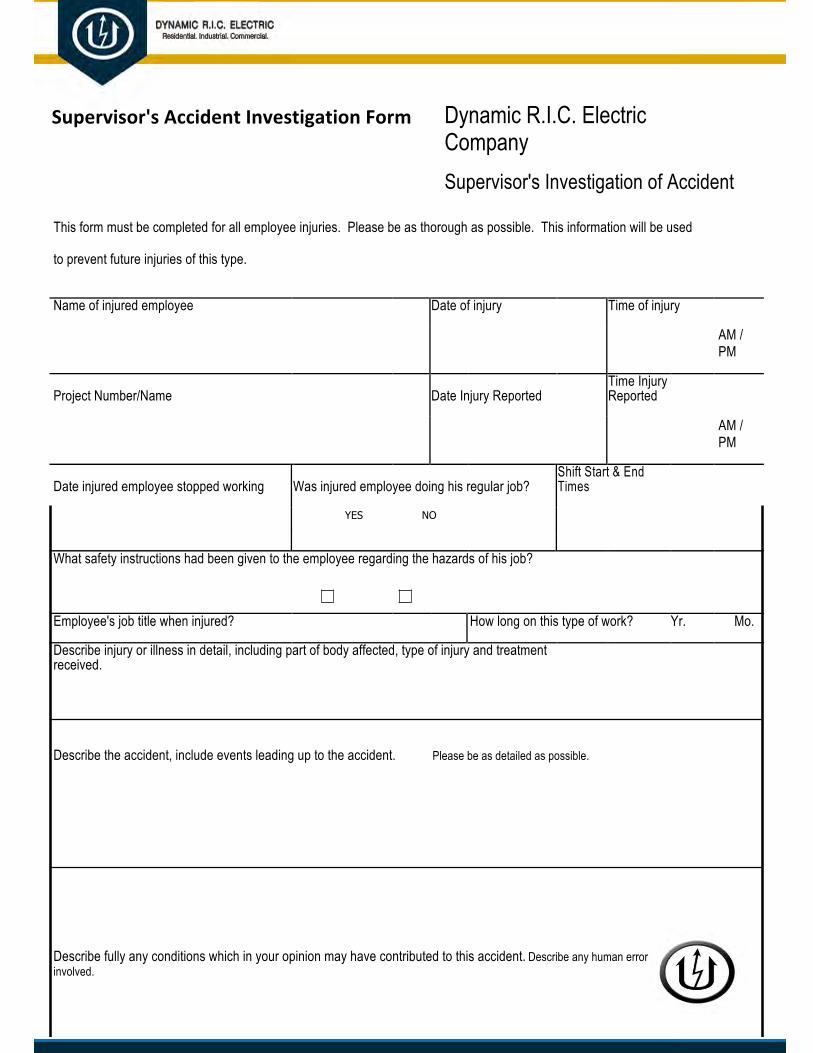
Supervisor's Accident Investigation Form Dynamic R.I.C. Electric Company Supervisor's Investigation of Accident
This form must be completed for all employee injuries. Please be as thorough as possible. This information will be used
to prevent future injuries of this type.
Name of injured employee Date of injury Time of injury
AM / PM
Project Number/Name Date Injury Reported Time Injury Reported
AM / PM
Date injured employee stopped working Was injured employee doing his regular job? Shift Start & End Times
YES NO
What safety instructions had been given to the employee regarding the hazards of his job?
Employee's job title when injured? How long on this type of work? Yr. Mo.
Describe injury or illness in detail, including part of body affected, type of injury and treatment received.
Describe the accident, include events leading up to the accident. Please be as detailed as possible.
Describe fully any conditions which in your opinion may have contributed to this accident. Describe any human error or machine error involved.

If machine error, has the condition been corrected? If "No", when will the condition be corrected?
What safety equipment was provided to employee at the time of the accident? Was it being properly used at the time of the injury?
Were there any witnesses to this injury? If so, please identify. When were you first notified of this injury?
What action has been taken to prevent a similar accident/injury?
Is there any additional information that you feel may be beneficial to the Safety Department?
Supervisor's Printed Name Supervisor's Signature Department Date

Supervisor's Investigation of Accident REVIEW BY PROJECT MANAGER
Project Manager's comments and instructions
Foreman's Printed Name Foreman's Signature Date
General Foreman's Printed Name General Foreman's Signature Date
Field Superintendant's Printed Name Field Superintendant's Signature Date
Project Manger' Printed Name Project Manager's Signature Date
This report is to be made in duplicate immediately after the accident in the supervisor's own handwriting. The duplicate is to be retained in the field office files.

Return to Work Policy Statement
R E T U R N T O W O R K P O L I C Y S T A T E M E N T
It is the policy of Dynamic R.I.C. Electric Company to maintain and support a Return to Work program. Our Return to Work program is intended to assist employees in recovering from a work-related injury, while at the same time, allowing an injured employee to remain a productive and integral part of Dynamic R.I.C. Electric Company. When a work-related injury occurs, our ultimate goal is to return that injured employee to work in a productive and essential capacity as soon as possible.
We are committed to maintaining a safe workplace for our employees, but safety is also your responsibility. If you become injured on the job and need medical attention, you must report your injury to your supervisor on the same day of the incident. Your supervisor will ensure that proper first aid is administered, or that medical treatment is sought; assist with filing an incident report; be involved in the subsequent accident investigation to identify and eliminate any hazards that may have been associated with your injury; and assist in the return-to-work process.
It is the policy of our company to provide meaningful work activity for all employees who temporarily become unable to perform all, or portions, of their regular work assignments due to work-related or non-work-related injury or illness. To facilitate this process, Return to Work duties may be in the form of either changed duties within the scope of a current position, or other available duties for a worker is qualified, or through a reduced work-hours schedule.
Dynamic R.I.C. Electric Company believes its employees are critical to our success. Through our Return to Work program, we are committed to assisting our injured employees to return to work as soon as medically appropriate, and to help our injured employees maintain their livelihood.

Return to Work Evaluation Form
Dynamic R.I.C. Electric Company
RETURN TO WORK EVALUATION FORM
(To be completed by the medical practitioner)
Employee:
D.O.B.: Date of impairment:
Diagnosis:
Prognosis:
Please complete the following items based on your estimated clinical evaluation. Any item that you do not believe you can answer should be marked N/A. Dynamic R.I.C. Electric Company has a Return to Work program for eligible employees and this evaluation form will help us determine return to work availability.
In an 8 hour workday, patient can (circle full capacity of each activity):
A. Sit 1 2 3 4 5 6 7 8 (hours)
B. Stand 1 2 3 4 5 6 7 8 (hours)
C. Walk 1 2 3 4 5 6 7 8 (hours)
Note: In terms of an 8-hour workday – Occasionally = 1% - 33%
Frequently = 34% - 66%
Continuously = 67% - 100%
Not at All Occasionally FrequentlyContinuously
4. Bend/Stoop

5. Squat6. Crawl7. Climb
8. Reach AboveShoulder Level
9. Crouch10. Kneel11. Balance12. Push/Pull
Carry:
q Up to 10 lbs. q 11 – 24 lbs. q 25 – 34 lbs. q 35 – 50 lbs.
q 51 + lbs.

Lift: Not at All Occasionally FrequentlyContinuously
a. Up to 10 lbs.b. 11 – 24 lbs.c. 25 – 34 lbs.d. 35 – 50 lbs.e. 51 + lbs.
Patient can use hands for repetitive action such as (circle “Yes” or “No”):
Simple Grasping Firm Grasping Fine Manipulation
A. Right Yes No Yes No Yes No
B. Left Yes No Yes No Yes No
Patient can use feet for repetitive movements as in operating foot controls, walking, etc. (Circle
“Yes” or “No” and “Total Hours”):
Right________ Left_________ Both________
Yes No Yes No Yes No
Hours: 1 2 3 4 5 6 7 8 1 2 3 4 5 6 7 8 1 2 3 4 5 6 7 8
Restriction of Activities
Involving:
None Mild Moderate Total
Unprotected Heights
Operate Moving Machinery
Temperature Changes
Operating Forklifts
Driving Automobiles
Dust, Fumes, & Gas Exposure

Can Patient perform some type of work?
If so, how many hours per day?
How long is the patient’s impairment expected to last:
Do these restrictions apply to activities outside of working hours?
In no, explain.
Physician Name: Date Completed:
Please print
Physician Signature: Phone #
Letter to Doctor
Date
Medical provider's name
Address
RE: Employee name/Injury Date
Dear ____________________,
(Employee's Name), the patient you are treating, is enrolled in Dynamic R.I.C. Electric Company’s
Return to Work program. As you know, Dynamic R.I.C. Electric Company provides temporary, modified work for employees suffering workplace injuries. The purpose of our Return to Work program is to provide temporary modified work for injured workers during their recovery and rehabilitation period. Temporary, modified tasks are offered as a means of lessening the emotional and financial strain that injuries often have on employees. We will cooperate fully with you in developing job tasks that allow (employee's name) to return to work without compromising (his/her) physical capabilities.
Dynamic R.I.C. Electric Company encourages release to modified, temporary work assignments as soon as possible after injury. We are eager to work within the limitations you may specify. We will take all necessary steps to ensure (employee's name) adheres to all restrictions, limitations, and therapies you deem necessary. Our goal is to return (employee's name) to full and unrestricted work as quickly as possible.
Please complete the attached Return to Work Evaluation form on (employee's name) so that we may implement or design a modified work program to fit applicable restrictions/capabilities.
Thank you for your assistance. If you have any questions about our Return to Work program, or about the job tasks developed for (employee's name.
Sincerely,
Dynamic R.I.C. Electric Company

ELECTRICAL
Electric Tool & Cord Color Chart
ELECTRIC TOOL AND CORD INSPECTION
M.28
All electric tools and extension cords must be tested quarterly. The following tape color codes must be used to designate when tool or cord was tested.
White Tape January, February and March
Green Tape April, May and June
Red Tape July, August and September
Orange Tape October, November and December
Any tool or extension cord found to be defective, must be tagged “Defective – Do Not Use.”

Electric Tool Inspection Record
ELECTRICAL TOOL INSPECTION RECORD
M.29
Description or Name Tool No. Electrician’s Name Date Color Code

Lockout-Tagout Checklist
Periodic – Annual Observation of Lockout Tagout Program
EMPLOYEE BEING OBSERVED PLANT # DEPT. #
BLDG. # MACHINE/EQUIPMENT/PROCESS EQUIP. #
OBSERVATION QUESTION YES NO COMMENTS
1. Has all energy-isolating device been located?
2. Does the plant provide devices specifically for
lockout/tagout procedures?
3. Are lockout/tagout devices durable enough to
withstand plant conditions?
4. When only tagout devices are used, are
attachments non-reusable, attachable by hand, self-
locking and non-releasable with minimum unlocking
strength of 50 lbs.?
5. Can the person using a lockout/tagout device be
easily identified?
Authorization:
6. Is an authorized person performing the
lockout/tagout?

Preparation:
7. Are affected employees notified when there is an
application or removal of lockout/tagout devices?
Shutdown:
8. Are normal “shutdown” procedures followed?
Energy Isolation:
9. Are energy isolating device(s) located and
energy source(s) separated from the machine?
Lockout/Tagout Device Application:
10. Are lockout/tagout devices placed on each
energy-isolating device?
Stored Energy:
11. Are potentially hazardous, stored or residual
energy relieved, disconnected or restrained?
Verification of Isolation:
12. Does the authorized employee verify that de-
energization of the equipment has been accomplished?

OBSERVATION QUESTION YES NO COMMENTS
Inspection:
13. Prior to removing locks/tags, has the work area
been inspected, nonessential items removed and
the machine components including guards, made
operationally intact?
Employee Notification:
14. Prior to removing locks/tags, have affected
employees been notified and the work area
inspected to ensure all employees are in a safe
position?
Lockout/Tagout Device Removal:
15. Have Lockout/Tagout devices been removed by
the person who applied them?
COMMENTS:
OBSERVER INFORMATION:
OBSERVER OBSERVER SIGNATURE TITLE DEPT. DATE
EMPLOYEE #

ENERGIZED WORK FORMS
Customer or Client Communication Form
DYNAMIC R.I.C. ELECTRIC COMPANY
Part 1 (of 3): Customer/Client Communication Form
Customer Name: ___________________________________________ Project Number: ___________________
Projected Start Date: ____________________ Timeframe required to complete task: _____________________
Description of the circuit or equipment: ___________________________________________________________
_____________________________________________________________________________________________
_____________________________________________________________________________________________
Function and location of the circuit or equipment: __________________________________________________
_____________________________________________________________________________________________
_____________________________________________________________________________________________
Dynamic R.I.C. Electric Company is dedicated to providing our customers the highest quality of service available. This not only includes stellar craftsmanship and safe work, it also includes the customer’s safety, the safety of their equipment and operations. One of our top goals is to protect our customers from an increased risk of loss.
Therefore, per relevant regulations and standards governing the performance of tasks on energized equipment
(29CFR1910.333, 29CFR1926.416 and NFPA 70E) as well as Dynamic R.I.C. Electric Company’s safety policy, it is requested that the above referenced circuit/equipment be de-energized in order to perform the work.

If the above referenced circuit/equipment is not capable of being de-energized or it is not possible to defer the work until the next scheduled outage, please describe why it is necessary to work on or near the exposed energized electrical conductor(s) or circuit part(s).
To assist you in providing this description: According to the above referenced regulations, standards and policy, there are only two acceptable explanations for not de-energizing circuits/equipment. These are:
1. If de-energizing would result in an increased, additional, or greater hazard. Examples of this might be that a loss ofpower could result in an environmental spill or a runaway process; a loss of power could result in the shutdown of ventilation fora hazardous atmosphere; loss of power to life-support equipment or emergency alarm systems.
2. If de-energizing is infeasible due to equipment design or operational limitations. Examples of this might be removing thesource of voltage for a single instrument circuit would require the complete shutdown of a continuous process; start-upor troubleshooting diagnostic and testing activities.
Account of why the circuit or equipment cannot be de-energized or the work deferred until the next scheduled outage: ____________________________________________________________________________
_____________________________________________________________________________________________
_____________________________________________________________________________________________
_____________________________________________________________________________________________
_____________________________________________________________________________________________
____________________________________________ ___________________
Customer or Client providing the above description / Title Date
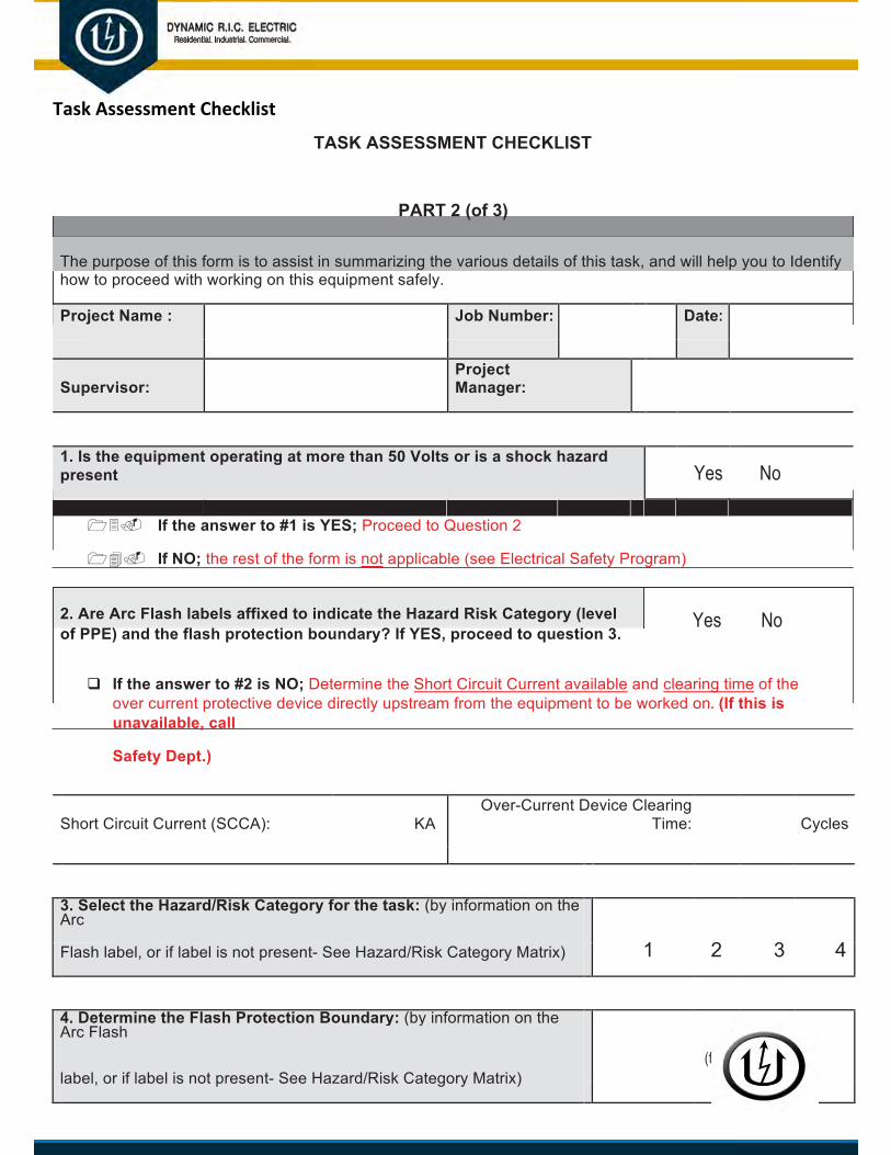
Task Assessment Checklist
TASK ASSESSMENT CHECKLIST
PART 2 (of 3)
The purpose of this form is to assist in summarizing the various details of this task, and will help you to Identify how to proceed with working on this equipment safely.
Project Name : Job Number: Date:
Supervisor: Project Manager:
1. Is the equipment operating at more than 50 Volts or is a shock hazardpresent Yes No
13. If the answer to #1 is YES; Proceed to Question 2
14. If NO; the rest of the form is not applicable (see Electrical Safety Program)
2. Are Arc Flash labels affixed to indicate the Hazard Risk Category (levelof PPE) and the flash protection boundary? If YES, proceed to question 3.
Yes No
q If the answer to #2 is NO; Determine the Short Circuit Current available and clearing time of theover current protective device directly upstream from the equipment to be worked on. (If this isunavailable, call
Safety Dept.)
Short Circuit Current (SCCA): KA Over-Current Device Clearing
Time: Cycles
3. Select the Hazard/Risk Category for the task: (by information on theArc
1 2 3 4 Flash label, or if label is not present- See Hazard/Risk Category Matrix)
4. Determine the Flash Protection Boundary: (by information on theArc Flash
(ft) (in) label, or if label is not present- See Hazard/Risk Category Matrix)

5. Is the fault energy level available at the location equal to or less than theparameters listed for each Equipment type? (Disregard if information was gatheredfrom the Arc Flash Label) Yes No
Î If the answer to #5 is YES; the table isapplicable.
Î If the answer to #5 is NO; further investigation and calculations arerequired. (Call the Safety Dept.)
6. Determine the Shock Protection Boundaries Below: (See the Approach Boundary Table)
Limited: (ft) (in) Restricted: (in)
Please note that only voltage rated tools and voltage rated gloves shall be used inside the limited approach boundary.
7. Select the required PPE for the Hazard Risk category – (See Energized Work Protective Clothing Matrix)
PPE & Insulating Material Required for this task
Hard Hat Hard hat liner
Safety Glasses or Safety Goggles Arc-rated jacket, parka, or rainwear
Hearing Protection (ear canal inserts) Arc-rated face shield
Heavy Duty Leather Gloves Arc-rated gloves
Leather Work Shoes Arc-rated balaclava (AR hood Sock)
Arc-rated arc flash suit jacket 4 cal/cm² 8 cal/cm² 25 cal/cm² 40 cal/cm²
Arc-rated arc flash suit 4 cal/cm² 8 cal/cm² 25 cal/cm² 40 cal/cm²
Arc-rated long-sleeve shirt 4 cal/cm² 8 cal/cm² 25 cal/cm² 40 cal/cm²
Arc-rated pants 4 cal/cm² 8 cal/cm² 25 cal/cm² 40 cal/cm²
Arc-rated coverall 4 cal/cm² 8 cal/cm² 25 cal/cm² 40 cal/cm²
SIGNATURE OF QUALIFIED PERSON COMPLETING THIS FORM
Name (Print Legibly)___________________________Title:__________
Signature______________________________ Date______________

Method of Procedure
Detailed Method of Procedure
Building Name: Address:
Customer Name: Project #
Building: Floor: Work Area:
Work Type: Construction Maintenance Emergency Repair Other (Specify)
Work Initiated By: Phone Number:
Work Approved By: Phone Number:
Project Manager (If Applicable): Phone Number:
Work Request Date: Date Requested for work
Risk Assessment: Critical Power Affected?
Building Engineers Assistance Required High YES
Systems Disabled/ Bypassed Medium NO
Security Assistance Required Low
Scope Of Work:

Detailed Method of Procedure
RESOURCE (Party
ITEM DATE & TIME INITIALS Responsible for Step) SEQUENCE OF EVENTS
1.

RESOURCE (Party
ITEM DATE & TIME INITIALS Responsible for Step) SEQUENCE OF EVENTS

Energized Work Permit
PART 3 (of 3)
Customer Name : Job Number:
Location / Area : Projected Start Date /
Time
The Detailed Method
of Procedure form has been completed? Form attached No
Is there a “One-Line” Diagram available for review? Yes (please attach) No
Shock Hazard Analysis Voltage Level Phase to Phase :
Approach Boundaries:AC: 130.4(D)(a) | DC: 130.4(D)(b) Limited: (ft) (in) Restricted: (ft) (in)
Flash Hazard Analysis
Flash Boundary Calculation Results : ______ (ft) _____ (in)
Hazard/Risk Category for the task: AC: [130.7(C)(15)(A)(b)] DC: [NFPA 70E, 130.7(C)(15)(B)] 1 2 3 4
ATPV rating (in cal/cm²) for FR Clothing: 4 (cat 1) 8 (cat 2) 25 (cat 3) 40 (cat 4)
Means employed to restrict access of unqualified personnel (check all that apply) Signs/Tags Barricade Attendants
Description of the Safe Work Practices to be employed: PPE & Insulating Material:
Restrict access to protect unqualified personnel Hard Hat
Eyewash/Body irrigation facilities available Ear Plugs
Fire Extinguisher accessible Insulating gloves Inspection Dates: _________ & _________
Nearest AED Location identified Leather protectors
Emergency Plan/Phone numbers posted Insulated sleeves
Communications equipment accessible Safety Glasses (ANSI Z.87 Compliant)
Supplemental Lighting (non-conductive) Arc Flash face shield
Fuse puller (non-conductive) FR Clothing
Rope/Hand-line (non-conductive) Safety Shoes
Portable GFCI for tools (test before use) Ladder (non-conductive side-rails)
Protective grounding set (inspect before use) Insulated mats ( voltage rated) Inspection Date: _______

Means to secure doors/panels Insulated blanket ( voltage rated) Inspection Date: _______
Test equipment required Insulated tools (voltage rated – 1000V)
QUALIFIED PERSON 1
Performing Work Safety Watch
Reviewed Task Assessment Checklist? Yes No
Reviewed Detailed Method of Procedure? Yes No
Agrees work can be done safely? Yes No
Name (Print Legibly)_________________________________________
Signature______________________________ Date______________
QUALIFIED PERSON 2
Performing Work Safety Watch
Reviewed Task Assessment Checklist? Yes No
Reviewed Detailed Method of Procedure? Yes No
Agrees work can be done safely? Yes No
Name (Print Legibly)_________________________________________
Signature______________________________ Date______________
Management Approval(s):
Electrically Knowledgeable Customer Representative Signature: Date: mm/dd/yyyy
Dynamic R.I.C. Electric Company Project Manager / VP Signature: Date: mm/dd/yyyy

Job Safety Briefing Form
JOB BRIEFING SUMMARY SHEET
The purpose of this form is to summarize all of the details discussed and a record of the participants at the required job briefing BEFORE each energized work activity takes place.
Project Name : Job Number: Date: mm/dd/yyyy
Supervisor: Project Manager:
CHECK ALL THAT APPLY
Introduction - The team discussed and identified:
15. A general overview and the goal of the work activity
16. All team members involved in the work activity were present and introduced
17. Methods of communication and contact info for all involved was distributed
18. All relevant work permits and documentation has been completed
□ Who is the on-site person in chargeName:_____________________ Title: ________________
□ Who is the on-site person in charge for customerName:_____________________ Title: ________________
The Briefing Identified:
q Hazards
q Voltages involved
q Skills required
q Secondary voltage sources
q All unusual work conditions or factors that could affect the work
q Personnel and individual job assignments
q Shock protection boundaries
q Available incident energy
q Potential for arc flash & the established arc flash boundary

q All breakers, switches, interlocks, and control methods are known and identified
q Safety procedures
q Emergency contact information
q Appropriate safety equipment on-site (First Aid Kit, Rescue Tripod, Sniffer, AED, etc…)
q Required PPE, tools and equipment to be used
q Methods, warning signage, barricades and equipment to control access is on-site
q Step-by-step plan (MOP) describing in detail, how the activity will take place
q Reviewed all relevant drawings or other data (if available)
q The customer contact is present and/or we have permission to proceed
q All Materials and parts required to do the work are on-site
q Task lighting, ventilation and any other work activity support equipment is on-site
q Journeymen to perform energized work activity – Names: __________________________ & ______________________________
Contingency Plan:
f. Discussed a “What if” option and all team members are aware of their role
g. Explained how the equipment is shut off in case of an emergency
h. Discussed Fire / Rescue contact plan – Entry / Egress for rescuers
□ Who is the Emergency Contact for Dynamic R.I.C. ElectricCompany
Name:_____________________ Title: ________________
□ Who is the Emergency Contact for the CustomerName:_____________________ Title: ________________
□ Step-by-step plan on recovery after an incident □ Emergency Exits □ How to account for employees □ Meeting Location
Dynamic R.I.C. Electric Company 1 of 2 Job Briefing

JOB BRIEFING SUMMARY SHEET
The purpose of this form is to summarize all of the details discussed and a record of the participants at the required job briefing BEFORE each energized work activity takes place.
Project Name : Job Number: Date: mm/dd/yyyy
Supervisor: Project Manager:
Specific questions and answers brought up during briefing
Sign in sheet for ALL participants of the job briefing
Dynamic R.I.C. Electric Company Employees

Customer Employees
Vendors, Subs, Suppliers, etc.… (List company / organization)
Other Discussion:

Approach Boundaries Table (AC Only)
APPROACH BOUNDARIES TABLE FOR SHOCK PROTECTION (Alternating-Current Only)
All dimensions represent the distance from energized conductor or circuit part to employee
(1) (2) (3) (4)
Nominal System Voltage Limited Approach Boundaryb Restricted Approach Boundaryb;
Range, Phase to Phasea Exposed Moveable Exposed Fixed Cicuit Part Includes Inadvertant Movement
Conductorc Adder
<50 V Not Specified Not Specified Not Specified
50 V - 150 Vd 3.0 m (10 ft 0 in) 1.0 m (3 ft 6 in) Avoid Contact
151 V - 750 V 3.0 m (10 ft 0 in) 1.0 m (3 ft 6 in) .3 m (1 ft 0 in)
751 V - 15 kV 3.0 m (10 ft 0 in) 1.5 m (5 ft 0 in) .7 m (2 ft 2 in)
15.1 kV - 36 kV 3.0 m (10 ft 0 in) 1.8 m (6 ft 0 in) .8 m (2 ft 7 in)
36.1 kV - 46 kV 3.0 m (10 ft 0 in) 2.5 m (8 ft 0 in) .8 m (2 ft 9 in)
46.1 kV - 72.5 kV 3.0 m (10 ft 0 in) 2.5 m (8 ft 0 in) 1.0 m (3 ft 3 in)
72.6 kV - 121 kV 3.3 m (10 ft 8 in) 2.5 m (8 ft 0 in) 1.0 m (3 ft 4 in)
138 kV - 145 kV 3.4 m (11 ft 0 in) 3.0 m (10 ft 0 in) 1.2 m (3 ft 10 in)
161 kV - 169 kV 3.6 m (11 ft 8 in) 3.6 m (11 ft 8 in) 1.3 m (4 ft 3 in)
230 kV - 242 kV 4.0 m (13 ft 0 in) 4.0 m (13 ft 0 in) 1.7 m (5 ft 8 in)
345kV - 362 kV 4.7 m (15 ft 4 in) 4.7 m (15 ft 4 in) 2.8 m (9 ft 2 in)
500 kV - 550 kV 5.8 m (19 ft 0 in) 5.8 m (19 ft 0 in) 3.6 m (11 ft 10 in)
765 kV - 800 kV 7.2 m (23 ft 9 in) 7.2 m (23 ft 9 in) 4.9 m (15 ft 11 in)

Note (1): For arc flash boundary, see 130.5(B)
Note (2): All dimensions are distance from exposed energized electrical conductors or circuit part to employee
a For single-phase systems, select the range that is equal to the system's maximum phase-to-ground voltage multiplied by
1.732. b See definition in Article 100 and text in 2015 NFPA 70E 130.4(D)(2) and Annex C for elaboration.
c Exposed Moveable Conductors describes a condition in which the distance between the conductor and a person is not under the control of the person. The term is normally applied to overhead line conductors supported by poles.
d This includes circuits where the exposure does not exceed 120 V.
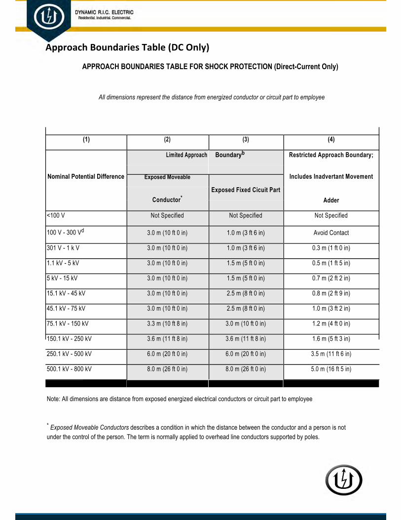
Approach Boundaries Table (DC Only)
APPROACH BOUNDARIES TABLE FOR SHOCK PROTECTION (Direct-Current Only)
All dimensions represent the distance from energized conductor or circuit part to employee
(1) (2) (3) (4)
Nominal Potential Difference
Limited Approach Boundaryb Restricted Approach Boundary;
Includes Inadvertant Movement Exposed Moveable
Exposed Fixed Cicuit Part Conductor* Adder
<100 V Not Specified Not Specified Not Specified
100 V - 300 Vd 3.0 m (10 ft 0 in) 1.0 m (3 ft 6 in) Avoid Contact
301 V - 1 k V 3.0 m (10 ft 0 in) 1.0 m (3 ft 6 in) 0.3 m (1 ft 0 in)
1.1 kV - 5 kV 3.0 m (10 ft 0 in) 1.5 m (5 ft 0 in) 0.5 m (1 ft 5 in)
5 kV - 15 kV 3.0 m (10 ft 0 in) 1.5 m (5 ft 0 in) 0.7 m (2 ft 2 in)
15.1 kV - 45 kV 3.0 m (10 ft 0 in) 2.5 m (8 ft 0 in) 0.8 m (2 ft 9 in)
45.1 kV - 75 kV 3.0 m (10 ft 0 in) 2.5 m (8 ft 0 in) 1.0 m (3 ft 2 in)
75.1 kV - 150 kV 3.3 m (10 ft 8 in) 3.0 m (10 ft 0 in) 1.2 m (4 ft 0 in)
150.1 kV - 250 kV 3.6 m (11 ft 8 in) 3.6 m (11 ft 8 in) 1.6 m (5 ft 3 in)
250.1 kV - 500 kV 6.0 m (20 ft 0 in) 6.0 m (20 ft 0 in) 3.5 m (11 ft 6 in)
500.1 kV - 800 kV 8.0 m (26 ft 0 in) 8.0 m (26 ft 0 in) 5.0 m (16 ft 5 in)
Note: All dimensions are distance from exposed energized electrical conductors or circuit part to employee
* Exposed Moveable Conductors describes a condition in which the distance between the conductor and a person is notunder the control of the person. The term is normally applied to overhead line conductors supported by poles.

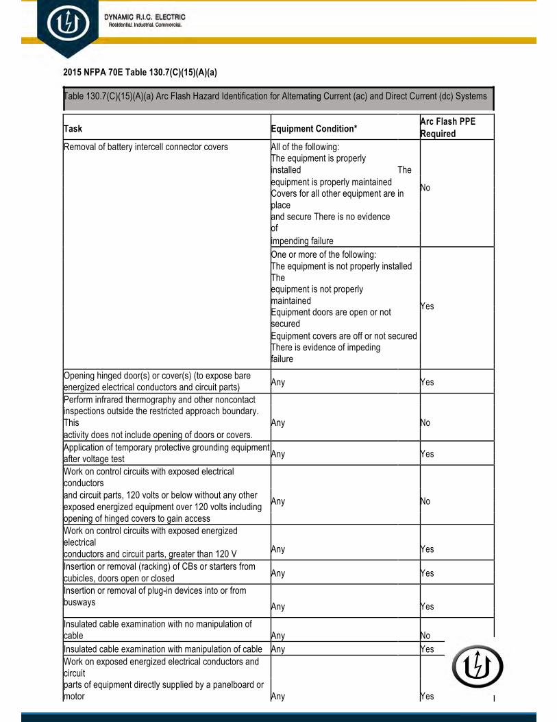
Arc Flash Hazard Identification Table
2015 NFPA 70E Table 130.7(C)(15)(A)(a)
Table 130.7(C)(15)(A)(a) Arc Flash Hazard Identification for Alternating Current (ac) and Direct Current (dc) Systems
Task Equipment Condition* Arc Flash PPE Required
Reading a panel meter while operating a meter switch Any No
Normal operation of a circuit breaker (CB), switch, contactor All of the following: or starter The equipment is properly installed The
equipment is properly maintained
No All equipment doors are closed and secured All equipment covers are in place and secured There is no evidence of impending failure
One or more of the following: The equipment is not properly installed The equipment is not properly maintained Yes Equipment doors are open or not secured Equipment covers are off or not secured There is evidence of impending failure
For ac systems: Work on energized electrical conductors and Any Yes circuit parts, including voltage testing For dc systems: Work on energized electrical conductors and
Any Yes circuit parts of series-connected battery cells, including voltage testing Voltage testing on individual battery cells or individual multi- All of the following: cell units The equipment is properly installed The
equipment is properly maintained No Covers for all other equipment are in place and secured There is no evidence of impending failure One or more of the following: The equipment is not properly installed The equipment is not properly maintained Yes Equipment doors are open or not

secured Equipment covers are off or not secured There is evidence of impending failure
Removal or installation of CBs or switches Any Yes Removal or installation of covers for equipment such as All of the following: wireways, junction boxes, and cable trays that does not The equipment is properly installed The
No expose bare energized electrical conductors and circuit parts equipment is properly maintained
There is no evidence of impending failure Any of the following: The equipment is not properly installed The Yes equipment is not properly maintained There is evidence of impending failure
Removal of bolted covers (to expose bare energized electrical conductors and circuit parts). For dc systems, this Any Yes includes bolted covers, such as battery terminal covers.
Dynamic R.I.C. Electric Company 1 Arc Flash Hazard Identification Table
2015 NFPA 70E Table 130.7(C)(15)(A)(a)
Table 130.7(C)(15)(A)(a) Arc Flash Hazard Identification for Alternating Current (ac) and Direct Current (dc) Systems
Task Equipment Condition* Arc Flash PPE Required
Removal of battery intercell connector covers All of the following: The equipment is properly installed The equipment is properly maintained No Covers for all other equipment are in place and secure There is no evidence of impending failure One or more of the following: The equipment is not properly installed The equipment is not properly maintained Yes Equipment doors are open or not secured Equipment covers are off or not secured There is evidence of impeding failure
Opening hinged door(s) or cover(s) (to expose bare Any Yes energized electrical conductors and circuit parts) Perform infrared thermography and other noncontact
Any No inspections outside the restricted approach boundary. This activity does not include opening of doors or covers. Application of temporary protective grounding equipment Any Yes after voltage test Work on control circuits with exposed electrical conductors and circuit parts, 120 volts or below without any other Any No exposed energized equipment over 120 volts including opening of hinged covers to gain access Work on control circuits with exposed energized electrical Any Yes conductors and circuit parts, greater than 120 V Insertion or removal (racking) of CBs or starters from Any Yes cubicles, doors open or closed Insertion or removal of plug-in devices into or from busways Any Yes
Insulated cable examination with no manipulation of cable Any No Insulated cable examination with manipulation of cable Any Yes Work on exposed energized electrical conductors and circuit
Any Yes parts of equipment directly supplied by a panelboard or motor

control center Insertion and removal of revenue meters (kW-hour at primary Any Yes voltage and current) For dc systems, insertion or removal of individual cells or Any Yes multi-cell units of a battery system in an enclosure For dc systems, insertion or removal of individual cells or Any No multi-cell units of a battery system in an open rack

2015 NFPA 70E Table 130.7(C)(15)(A)(a)
Table 130.7(C)(15)(A)(a) Arc Flash Hazard Identification for Alternating Current (ac) and Direct Current (dc) Systems
Task Equipment Condition* Arc Flash PPE Required
For dc systems, maintenance on a single cell of a battery Any No system or multi-cell units in an open rack For dc systems, work on exposed energized electrical
Any Yes conductors and circuit parts or utilization equipment directly supplied by a dc source Arc-resistance switchgear Type 1 or 2 (for clearing times of
All of the following:
<0.5 sec with a prospective fault current not to exceed the arc-resistant rating of the equipment) and metal enclosed interrupter switchgear, fused or unfused of arc resistant type construction tested in accordance with IEEE C37.20.7:
The equipment is properly installed The No equipment is properly maintained
Insertion or removal (racking) of CBs from cubicles All equipment doors are closed and secured
Insertion or removal (racking) of ground and test device All equipment covers are in place and
Insertion or removal (racking) of voltage transformers on or
secured There is no evidence of impending
off the bus failure
One or more of the following: The equipment is not properly installed The equipment is not properly maintained Yes Equipment doors are open or not secured Equipment covers are off or not secured There is evidence of impending failure
Opening voltage transformer or control power transformer Any Yes compartments Outdoor disconnect switch operation (hookstick operated at 1 Any Yes kV through 15 kV Outdoor disconnect switch operation (gang-operated, from Any Yes grade) at 1 kV through 15 kV
Note: Hazard identification is one component of risk assessment. Risk assessment involves a determination of the likelihood of occurrence of an incident, resulting from a hazard that could cause injury or damage to health. The assess men of the likelihood of occurrence contained in this table does not cover every possible condition or situation. Where the table indicates that arc flash PPE is not required, an arc flash is not likely to occur.
*The phrase properlyinstalled , as used in this table, means that the equipment is installed in accordancewith applicable industry codes and standards and the manufacturer's recommendations. The phraseproperlymaintained , as used in this table, means that the equipment has been maintained in accordancewith the manufacturer's recommendations and applicable industry codes and standards. The phraseevidenceofimpendingfailure , as used in this table, means that there is evidence of arcing, overheating,loose or bound equipment parts, visible damage, deterioration, or other damage.

Arc Flash PPE Categories (AC Only)
Table 130.7(C)(15)(A)(b) Arc-Flash Hazard PPE Categories for Alternating Current (ac) Systems
Equipm ent Arc Flash PPE Category Arc-Flash Boundary
Panelboa rds or other equipment rated 240V and below
Paramete
1 485 mm (19 in.)
cycles) f
rs: Maximum of 25 kA short-circuit current available; maximum of 0.03 sec (2 ault clearing time; working distance 455 mm (18
in.)
Panelboa rds or other equipment rated >240V and up to 600V
Paramete
2 900 mm (3ft.)
fault clea
rs: Maximum of 25 kA short-circuit current available; maximum 0.03 sec (2 cycles) ring time; working distance 455 mm (18 in.)
600-V cla ss motor control centers (MCCs)
Paramete
2 1.5m (5 ft)
cycles) f
rs: Maximum of 65 kA short-circuit current available; maximum of 0.03 sec (2 ault clearing time; working distance 455 (18 in.)
600-V cla ss motor control centers (MCCs)
Paramete
4 4.3 m (14 ft)
cycles) f
600-V cla
rs: Maximum of 42 kA short-circuit current available; maximum of 0.33 sec (20 ault clearing time; working distance 455 mm (18
in.)
ss switchgear (with power circuit breakers or fused switches) and 600 V class

swit chboards
4 6 m (20 ft)
Paramete
cycles) f
r s: Maximum of 35 kA short-circuit current available; maximum of up to 0.5 sec (30 ault clearing time; working distance 455 mm (18 in.)
Other 600
Paramete
2 1.5 m (5 ft)
cycles) f
-V class (277 V through 600 V, nominal) equipment
r s: Maximum of 65 kA short circuit current available; maximum of 0.03 sec (2 ault clearing time; working distance 455 mm (18
in.)
NEMA E2 (fused contactor) motor starters, 2.3 kV through 7.2 kV
Paramete
4 12m (40 ft)
cycles) f
r s: Maximum of 35 kA short-circuit current available; maximum of up to 0.24 sec (15 ault clearing time; working distance 910 mm (36 in.)
Metal-cl ad switchgear, 1 kV through 15 kV
Paramete
4 12m (40 ft)
cycles) f
r s: Maximum of 35 kA sort-circuit current available; maximum of up to 0.24 sec (15 ault clearing time; working distance 910 mm (36 in.)
Arc-resis
perspecti
N/A (doors closed) N/A (doors closed) enclosed i
accor
tant switchgear Type 1 or 2 [for clearing times of <0.5 sec (30 cycles) with a ve fault current not to exceed the arc-resistant rating of the
equipment], and metal-
nterrupter switchgear, fused or unfused of arc-resistant-type construction, tested in dance with IEEE C37.20.7, 1 kV through 15 kV
Paramete r s: Maximum of 35 kA short-circuit current available; maximum of up to 0.24 sec (15 4 (doors open) 12 m (40 ft)

cycles) fault clearing time; working distance 910 mm (36 in.)
Other equ i pment 1 kV through 15 kV
Paramete
4 12m (40 ft)
cycles) f
r s: Maximum of 35 kA short-circuit current available; maximum of up to 0.24 sec (15 ault
clearing time; working distance 910 mm (36 in.)
Note: fnumber
or equipment rated 600 volts and below, and protected by upstream current-limiting fuses or current-limiting circuit breakers sized at 200 amperes or less, the arc flash PPE category can be reduced by one but not below arc flash PPE category 1.

Arc Flash PPE Categories (DC Only)
Table 130.7 (C)(15)(B) Arc-Flash Hazard PPE Categories for Direct Current (dc) Systems
Equipm Arc Flash PPE Category Arc-Flash Boundary
Storage supply 100V > VParametVoltage:Maximu2 sec @
Short-cir
ent
batteries, dc switchboards, and other dc sources oltage < 250V ers: 250V m arc duration and working distance:
455 mm (18 in.)
cuit current < 4kA 1 900 mm (3ft.)
4 kA ≤ s h ort-circuit current < 7 kA 2 1.2 m (4 ft)
7 kA ≤ s h ort-circuit current 15 kA 3 1.8 m (6 ft)
Storage supply 250V ≤ VParametVoltage:Maximu2 sec @
Short-cir
batteries, dc switchboards, and other dc sources oltage ≤ 600 V ers: 600V m arc duration and working distance:
455 mm (18 in.)
cuit current 1.5 kA 1 900 mm (3ft.)
1.5 kA ≤ short-circuit current < 3kA 2 1.2 m (4 ft)
3 kA ≤ s h ort-circuit current 7 kA 3 1.8 m (6 ft)
7 kA ≤ s 4 2.5 m (8 ft)
Note: Apthefollowin
h ort-circuit current < 10 kA
parel that can be expected to be exposed to electrolyte must meet both of g conditions:
(1) Be ev aluated for electrolyte protection in accordance with ASTM F1296, Standard Guide for Evaluating Chemical Protective Clothing

(2) Be arc -rated in accordance with ASTM F1891, Standard Specification for Arc Rated and Flame Resistant Rainwear, or equivalent
EWP
Flow Charts
NORMAL OPERATION OF EQUIPMENT
START
IS THE T
RAT
ED
600
VAC
AND LESS
NORMA
NO
DISCONTINUE CHART AND CONTACT SUPERVISOR FOR
FURTHER INSTRUCTION
(note 1)
TO BE PERFORMED BY APPROVED QUALIFIED PERSON(S) ONLY (INCL. PANELBOARDS, SWITCHBOARDS, DISCONNECTS & MOTOR CONTROL CENTERS)
YES
YES
IS THE IS THE ARE ARE
IS THERE
EQUIPMENT
YES
EQUIPMENT
YES
EQUIPMENT
YES
EQUIPMENT
YES
IMPEND
ASK CONSIDERED L
OPERATION?
ANY EVIDENCE OF ING
FAILURE? (note 2)
PROPERLY PROPERLY
DOORS COVERS IN
INSTALLED? MAINTAINED? CLOSED AND PLACE AND
NO
(note 3) (note 4) SECURED? SECURED?
ARC RATED PPE IS
NOT REQUIRED- CONDUCT THE WORK SAFELY
NO NO NO NO

WEAR A
IF NO LA
RC RATED PPE AS LISTED ON ARC FLASH LABEL.
BEL IS PRESENT, CONTACT SUPERVISOR OR PROJECT MANAGER FOR FURTHER INSTRUCTION
NOTES:
1 - NOR MAL OPERATION:
InteractproperlyExamplOperatiResetti
ing with enclosed electrical equipment with the parameters if its intended design criteria without exposing yourself to energized parts. The equipment must have all covers and screws installed. All openings (i.e.: knockouts, or breaker spaces) must be covered or closed. e s of Normal Operation n g a circuit breaker, disconnect switch, contactor or starter. ng a tripped breaker when the cause is known and from an overload, not a fault condition.
2 - IMPE NDING FAILURE:
• Evidence such as arcing, overheating, loose or bound equipment parts, visible damage, or deterioration. (In some cases, it may be necessary to contact the utility company for determination)
3 - PROThe equiDoes th
PERLY INSTALLED: pment has been installed in accordance with applicable industry codes and standards. e equipment appear to be properly installed?
4 - PROThe equiIs this eIs thereIf the ab
PERLY MAINTAINED: pment has been maintained in accordance with the applicable industry codes and standards. q uipment currently being installed or controlled by Dynamic R.I.C. Electric Company? a maintenance or testing label applied to the equipment? ove two questions are “no”, ask the customer (or customer’s representative) if the equipment has been maintained.

ST
WI
ART
LL THE WORK
EXPOSE YES
LIVE PARTS*?
NO
FOLLO
ENERGI
NORM
W APPROPRIATE
SAFETY STANDARDS FOR DE-
ZED WORK OR
AL OPERATIONS
* EXA
EXPO
Therminspec
Operacover
Rem
Voltag
Remlive paplace)
Applicdevice
Insert
MCC
Insertcubicl
MPLES OF COMMON TASKS THAT
SE LIVE PARTS:
ography or other non-contact tion
te breakers or fused switches with s off
ove or install CB or fused switches
e Testing / Troubleshooting
oving covers of equipment to expose rts (even if dead-front is still in
ation of temporary grounding s
ing or removing starter buckets in
ing or removing (racking) CB’s from es
ENERGIZED WORK FLOW CHARTTO BE PERFORMED BY APPROVED QUALIFIED PERSON(S) ONLY
IS THE TASK: YES YES YES WEAR APPROPRIATE IS THE INCIDENT ENERGY LE
SS THAN 40 CAL/CM²? PPE, REVIEW MOP&
SAFETY BRIEFING
1. TROUBLESHOOTING?2. VOLTAGE TESTING?
3. IR SCANNING?
ARE ARC FLASH LABELS
AFFIXED, INDICATING INCIDENT ENERGY OR
PPE LEVEL?
NO
NO NO
YES IS THIS SERVICE
NO
CONTACT SAFETY
DEPARTMENT IS THE EQUIPMENT
120/208V (AC) OR ENTRANCE
BELOW? EQUIPMENT?
WEAR AT LEAST HRC 2
PPE, REVIEW MOP &
SAFETY BRIEFING
NO YES
COMPLETE FORMS: THEN
CONDUCT WORK
ACCORDING TO THE PRESCRIBED PLAN
1. TASK ASSESSMENT CHECKLIST2. METHOD OF PROCEDURE3. SAFETY BRIEFING
COMPLETE
THEN
COMPLETE COMPLETE
METHOD OF THE
N ENERGIZED
HAVE PROJECT MANAGER INITIATE
SENDING THE CUSTOMER/CLIENT
COMMUNICATION FORM TO THE
TASK ASSESSMENT
CHECKLIST PROCEDURE WORK PERMIT
CLIENT THEN
THEN
THEN WAIT FOR APPROVAL, ONCE
RECEIVED…
CONDUCT WORK

THEN ACCORDING TO THE
RECEIVED… PRESCRIBED PLAN COMPLETE THE JOB
THEN
WA ITBRIEFING SUMMARY SHEET FOR APPROVAL , ONCE

START
ELECTRICAL LOCKOUT / TAGOUT (LO-TO FLOW CHART) TO BE PERFORMED BY APPROVED QUALIFIED PERSON(S) ONLY
DETERMINE ALL
POSSIBLE BEFORE IS THERE ANY IS THE IS THE ARE
OF ELECT
SOURCES
RICAL NEXT OPERATING THE EVIDENCE OF NO EQUIPMENT YES EQUIPMENT YES EQUIPMENT
ARE
YES EQUIPMENT
OPEN
NEXT (TURN-OFF)
SUPPLY TO THE
DISCONNECTING IMPENDING PROPERLY PROPERLY DOORS COVERS IN DISCONNECTING
SPECIFIC MEANS, ASK FAILURE? INSTALLED? MAINTAINED? CLOSED AND PLACE AND MEANS FOR
EQUIPMENT
YOURSELF: (note 1) (note 2) (note 3) SECURED? SECURED? EACH SOURCE
YES
NOTES
1 - IM
Eviden
bound deteri
2 -
The eqapplic
Does t
installe
3 -
The eqwith th
Is thisby Dyn
Is therequip
:
PENDING FAILURE:
ce such as arcing, overheating, loose or
equipment parts, visible damage, or oration.
PRO PERLY INSTALLED:
uipment has been installed in accordance with able industry codes and standards.
he equipment appear to be properly
d?
PRO PERLY MAINTAINED:
uipment has been maintained in accordance e applicable industry codes and standards.
equipment currently being installed or controlled amic R.I.C. Electric Company?
e a maintenance or testing label applied to the ment?
NO NO NO NO NEXT
If the above two questions are “no”, ask the customer (or customer’s representative) if the equipment has been maintained.
WEAR ARC RATED PPE AS LISTED ON ARC FLASH LABEL.
IF NO LABEL IS PRESENT, CONTACT SUPERVISOR OR PROJECT MANAGER FOR FURTHER
INSTRUCTION
THEN
DISCONTINUE
CHART AND
CONTACT
SUPERVISOR FOR FURTHER
INSTRUCTION OPEN (TURN-OFF) DISCONNECTING MEANS
FOR EACH SOURCE
NEXT

Wear arc rated PPE as listed on arc flash label. If no label is present, contact Supervisor or Project Manager for further instruction. Ensure that you have an adequately rated voltage detector and that it is on the proper setting
Test the voltage detector on a known live circuit. Once verified, resume LOTO
Wherever possible, visually verify that all blades of the disconnecting device(s) are fully open, or that drawout-type breakers are withdrawn to the fully disconnected position
Apply lockout / tagout device (ensure tag has appropriate contact info)
Test each phase conductor or circuit part (phase to phase and phase to ground)

RE-TO
ENERGIZATION OF ELECTRICAL CIRCUITS (LO-TO)BE PERFORMED BY APPROVED QUALIFIED PERSON(S) ONLY
STAR
CON
INSP
WOR
(NOT
CONDUCT SAFETY
BRIEFING FOR
AFFECTED
PERSONNEL
(NOTE 2)
REMOVE EACH
LOCK AND TAG
FROM CIRCUITS
(NOTE 3)
VERIFY THAT ALL
PERSONNEL ARE
CLEAR OF
EQUIPMENT
(NOTE 4)
WHEN
REQUIRED WEAR
ARC RATED PPE
(NOTE 5)
CLOSE
(TURN-ON)
CONNECTING
MEANS FOR
EACH SOURCE
NOTE
T
DUCT TESTS AND E
CTIONS OF K AREA
E 1)
S:
Thesenerg
e requirements shall be met, in the order given, before circuits or equipment are reenergized, even temporarily. If it is required that circuits are to be ized temporarily for testing or other means, the same control measures shall be reapplied as outlined on the reverse side of this card.
A quahave
lified person shall conduct tests and visual inspections, as necessary, to verify that all tools, electrical jumpers, shorts, grounds, and other such devices been removed, and all exposed conductors are protected, so that the circuits and equipment can be safely energized.
Warn all potentially affected employees exposed to the hazards associated with reenergizing the circuit or equipment to stay clear of circuits and equipment.
Lockwork
s / Tags shall be removed by the employee who applied them, or under his or her direct supervision. However, if this employee is absent from the place, then the lock or tag may be removed by a qualified supervisor designated to perform this task provided that:
The sThe s
upervisor ensures that the employee who applied the lock or tag is not available at the workplace, and upervisor ensures that the employee is aware that the lock or tag has been removed before he or she resumes work at that workplace.
Cond
Whe
uct a visual determination that all employees are clear of the circuits and equipment to be re-energized, and all affected equipment downstream. n required,
wear ARC RATED PPE suitable for protection from the hazard.

4. Incoming Voltage from the Utility Feed3 Phase short circuit contribution (max & min): -
X/R (reactance/resistance) ratio: Pre fault voltage tolerance percentage (max & min): 5. Cable/Wiring from the Transformer to the OCPD
CHECKLIST FOR ARC FLASH ASSESSMENT TO BE PERFORMED BY APPROVED QUALIFIED PERSON(S) ONLY
1. R EQUIRED – The Equipment
Wh
Wh
Is
at is the bus voltage: at is
the equipment type: the
equipment grounded?: □ Yes □ No
2.Eq
REQUIRED – Overcurrent Protective Device Upstream of uip.
Ma
Wh
Is i □ Yes □ No
Bre
nufacturer? (PICTURE) at
is the device model: t current-
limiting: aker settings
(PICTURE): □ Yes □ No
3. TOC
ransformer Rating (located upstream of the PD) * See Note
Pri
PRIMARY
SECONDARY Pri
PRIMARY
SECONDARY Typ
No
Z%X/R
Impeda
mary and secondary connection:
mary and secondary bus voltage:
e of transformer:
minal kVA:
(Impedance):
(reactance/resistance ratio):
nce tolerance (+ or -):
MAX MIN
MAX MIN
□ Copper □ Aluminum
Is it copper or aluminum:
What is the cable size:
AWG
What is the length:
Quantity per phase:
6. Motors or Generators Downstream Affecting Safe Operation?
Size:
Quantity:
* Note
Transformer information, though not required, is vital in providing accurate data. Without this information, the calculated incident energy is commonly in excess of 40 calories per squared centimeter.

BASIC PROJECT SAFETY CHECKLISTS
THESE FORMS MUST BE COMPLETED ON ALL DYNAMIC R.I.C. ELECTRIC COMPANY PROJECTS DAILY TASKS TO BE PERFORMED
JOB SAFETY ANALYSIS (JSA)
EQUIPMENT PRE-OPERATION INSPECTION CHECKLIST*
LADDER INSPECTION CHECKLIST
EXCAVATION INSPECTION CHECKLIST *
SCAFFOLDING INSPECTION CHECKLIST *
PERSONAL FALL PROTECTION SYSTEM
WEEKLY TASKS TO BE PERFORMED
TOOL BOX SAFETY TALK
WEEKLY SAFETY INSPECTION CHECKLIST
EACH INDIVIDUAL VEHICLE OR PIECE OF EQUIPMENT MUST HAVE ITS OWN INDIVIDUAL INSPECTION SHEET. ONCE COMPLETED, THESE
FORMS SHOULD BE RETAINED BY THE USER UNTIL THE END OF THE SHIFT; THEN RETURNED TO THE FOREMAN WHEN SIGNING OUT
ON THEIR JSA. DEPENDING ON THE SCOPE OF YOUR PROJECT, ADDITIONAL FORMS MAY BE REQUIRED. IF YOU HAVE ANY
QUESTIONS, PLEASE CONTACT THE SAFETY DIRECTOR FOR ASSISTANCE.
*NOTE
INSPECTION MAY BE REQUIRED MORE FREQUENTLY BASED ON CHANGING CONDITIONS. EXAMPLES OF THESE CHANGES INCLUDE,
BUT ARE NOT LIMITED TO:
AFTER RAINSTORMS, HIGH WINDS OR OTHER OCCURRENCE WHICH MAY INCREASE HAZARDS, AND
WHERE THERE IS INDICATION OF FAILURE, OR YOU CAN REASONABLY ANTICIPATE AN EMPLOYEE WILL BE EXPOSED TO HAZARDS.

Checklist for Arc Flash Assessments
Items Needed for Task Based (limited) Arc Flash Analysis
Listedinorderofimportancetothisstudy
REQUIRED- The Equipment
What is the bus voltage:
What is the equipment type: Please choose item
Is the equipment grounded:
REQUIRED- Overcurrent Protective Device (OCPD)
Who is the manufacturer (PICTURE of DEVICE):
What type of device: Select One
Is it current-limiting:
Are there individual settings (PICTURE):
SUGGESTED *seenote- Transformer Rating (thistransformerislocatedupstreamoftheOCPD)
Primary and secondary connection: Select Primary Select Secondary Primary and secondary bus voltage:
Type of transformer: Select one
Nominal kVA: Z%:
X/R (reactance/resistance ratio):
Impedance tolerance (+ or -):
Incoming Voltage from Utility Feed
3 Phase short circuit contribution (max & min): X/R (reactance/resistance) ratio:
Pre-fault voltage tolerance percentage (max & min):
Cable/Wiring from the Transformer to the OCPD
Is it copper or aluminum:
What is the cable size: Select Size (AWG)
What is the length: Quantity per phase:
Motors or Generators Downstream that Could Affect our Safe Operation?

Size:
Quantity:

Energized Work Protective Clothing Table
Energized Work Protective Clothing Matrix PPE CATEGORY PERSONAL PROTECTIVE EQUIPMENT
Arc-Rated Clothing, Minimum Arc Rating of 4 cal/cm2 (see Note 1)
1 • Arc-rated long-sleeve shirt and pants or arc rated coverall
• Arc-rated face shield (see Note 2) or arc flash suit hood • Arc-rated jacket, parka, rainwear, or hard hat liner (AN) Protective Equipment • Hard hat • Safety glasses or safety goggles (SR) • Hearing protection (ear canal inserts)
• Heavy duty leather gloves (see Note 3)• leather footwear (AN)
Arc-Rated Clothing, Minimum Arc Rating of 8 cal/cm2 (see Note 1) • Arc-rated long-sleeve shirt and pants or arc rated coverall
2• Arc-rated flash suit hood or• Arc-rated face shield (see Note 2) and Arc-rated balaclava• Arc-rated jacket, parka, rainwear, or hard hat liner (AN)Protective Equipment• Hard hat• Safety glasses or safety goggles (SR)• Hearing protection (ear canal inserts) • Heavy duty leather gloves (see Note 3)• leather footwear (AN)
Arc-Rated Clothing selected so that the System Arc Rating meets the required Minimum Arc Rating of 25 cal/cm2 (see Note 1) • Arc-rated long-sleeve shirt (AR)• Arc-rated pants (AR)
3• Arc-rated coverall (AR)• Arc-rated arc flash suit jacket (AR) • Arc-rated arc flash suit pants (AR) • Arc-rated arc flash suit hood• Arc-rated gloves (see Note 1) • Arc-rated jacket, parka, rainwear, or hard hat liner (AN) Protective Equipment• Hard Hat• Safety glasses or safety goggles (SR)• Hearing protection (ear canal inserts)• Leather footwear
Arc-Rated Clothing selected so that the System Arc Rating meets the required Minimum Arc Rating of 40 cal/cm2 (see Note 1) • Arc-rated long-sleeve shirt (AR)• Arc-rated pants (AR)
4• Arc-rated coverall (AR)• Arc-rated arc flash suit jacket (AR) • Arc-rated arc flash suit pants (AR) • Arc-rated arc flash suit hood• Arc-rated gloves (see Note 1) • Arc-rated jacket, parka, rainwear, or hard hat liner (AN) Protective Equipment• Hard Hat• Safety glasses or safety goggles (SR)• Hearing protection (ear canal inserts) • Leather footwear

ENERGIZED WORK PROGRAM INFORMATION
10 Things to Know About Arc Flash
10 THINGS TO KNOW ABOUT ARC FLASH
Arc flash explosions do not happen… I have never seen one! Seriously? We hope you never will see an arc flash accident. Unfortunately, electrical work by its very nature is dangerous due to the high energy levels involved and, until an accident occurs, electricity is odorless, colorless, and invisible. Being an electrician is the third most dangerous profession, according to OSHA. In its article “The Danger of Arc Flash,” July 2009, FireEngineering magazine said arc flash, “kills two workers a day, every day, year in and year out” and often these accidents “may occur when you perform routine maintenance” so, the likelihood that you will complete your career without knowing an arc flash victim is quite slim.
NFPA-70E is thestandard governing arc flash – Well, not really. It’s really about reducing live work by de-energizing a circuit first and putting it in an electrically safe condition beforestarting to work.
AFH labeling equals compliance with NFPA-70E – To work on any energized equipment above 50 volts, an energized work permit is required. A work permit is critical and cannot be bypassed by a simple labeling system. Employers and management are directly responsible for work permitting, safety programs, training and planning. Article 130.5(D) Equipment Labeling states: “Switchboards,panelboards,industrialcontrolpanels,andmotor
controlcentersthatareinotherthandwellingoccupanciesandarelikelytorequireexamination,adjustment,servicing,ormaintenancewhileenergizedshallbefieldmarkedtowarnqualifiedpersonsofpotentialelectricarcflashhazards.Themarkingshallbelocatedsoastobeclearly
visibletoqualifiedpersonsbeforeexamination,adjustment,servicing,ormaintenanceoftheequipment.”This is also repeated in NFPA 70 (NEC) Article 110.16. In essence, these Articleswarn qualified workers of potential danger — it doesn’t give anyone authority or consent to work on energized equipment simply because he or she has complied with the PPE requirements label.
Arc flash analysis is simply panel labeling - Arc flash analysis is about hazard reduction. It is NOT merely PPE or wardrobe selection.
Assessing equipment under 240 volts from a transformer rated below 125 kVA isn’t necessary - OSHA regulations and NFPA-70E standards mandate all equipment
operating at 50 volts and higher must be tested for electrical shock and potential AFH. IEEE 1584 states, “Equipmentbelow240Vneednotbeconsideredunlessitinvolvesatleastone 125kVAorlargerlow-impedancetransformerinitsimmediatepowersupply.” But this onlyrefers to incident energy calculations. The NFPA 70E Technical Committee recognized the existing hazards and eliminated this verbiage from its own standard in 2012. Employers are responsible for assessing all equipment operating at 50 volts and higher for other dangers, including shock and overload conditions, which may cause fire, electrocution, or other hazards.

Regular infrared scans of equipment rule out doing an arc flash analysis - Arc flash can be caused by equipment failure or loose connections, but most injuries are caused by human error and will only be avoided through regular analysis of equipment, work practices, and safety training programs.
Beyond the Motor Control Center (MCC), it isn’t necessary to check equipment for AFH – Just because the MCC is the final access point of power for motor loads, doesn’t mean there isn’t a need to assess other loads, which are fed from it.
Current-limiting fuses reduce most AFH – These don’t thoroughly address the duration component of arc flash. A current-limiting fuse will mitigate AFH only if the fault current is high enough.
There’s no AFH if there’s no exposed, energized conductors or circuit parts –
For most equipment, the probability of an arc flash may be very low, but it’s certainly not impossible. Inserting or removing draw-out circuit breakers, bus plugs and MCC buckets can cause an arc flash where, normally, there is no perceived hazard — “normally” operating electrical equipment has been known to fail.
Downstream arc flash hazards are always less violent than upstream arc flash hazards – run a full assessment, up and downstream, don’t stop at hazard level 1 or 2 and be the one who finds out the hard way that this dead wrong.

Design & Integration
Using Good Design to Reduce Arc Flash Hazard (AFH)
Three key factors may determine the intensity of an arc flash harm on you:
The quantity of fault current available in your system
The time until an arc flash fault is cleared
Your distance from an arc
A variety of choices in design and equipment configuration can be made that affect these factors and reduce the incidence of AFH.
The best arc flash and fault analysis programs are based on the test results in IEEE-1584 and on the recommendations of NFPA-70E. These programs can identify the grade of Personal Protective Equipment (PPE) clothing required by operators and create warning signs for electrical equipment stating the PPE required when working near energized equipment. These programs should calculate quickly and accurately the effects of flowing faults in three-phase, single-phase and DC power distribution systems.
Equipment Integration
Reducing your need to open that cabinet may be one of the best ways to reduce the incident of arc flash in your facility. People open cabinets for lots of reasons but, typically, it’s because they don’t know what’s going on in there. You may know there’s a problem; maybe you are getting an alarm or a circuit has tripped. But what if you could get that information, automatically, without opening the cabinet?
By linking your equipment — motors, drives, switchgear, to a communications network architecture, you can monitor and pull diagnostic data, perform trend and root-cause analyses, and see potential problems before sending an electrician into the plant to deal with them. Over time, this could mean your workers are opening electrical cabinets less often. This data may not stop arc flash, but you can organize and manage your power infrastructure in such a way that you will significantly reduce your exposure to potential hazard.

Needs & Benefits of Policy
NEEDS AND BENEFITS OF OUR POLICY
THE NEED
PROTECTION OF ELECTRICIANS
Working around electricity has always been dangerous. There is a need to protect workers from these hazards:
Electrical Shock - The risk of electrical shock is a well-recognized hazard. Insulated gloves have long been recognized as the Personal Protective Equipment for this hazard.
Arc Flash & Arc Blast - The Arc hazard is now greater due primarily to utilities increasing their distribution system capacities to keep up with growth. This has caused available fault currents to significantly increase, creating a work environment for our electrician’s where exposure to arc flash and blast forces are greater than ever before.
PROTECTION OF PROPERTY
We must also recognize the need for protection of electrical equipment and property. In every case of arc flash and arc blast there is damage to property. If an electrical incident involving energized electrical equipment results in a fire, there will be significant additional damage to the facility.
PROTECTION OF BUSINESS PROCESSES
We are providing services to an ever -changing business world. The business world operates at a pace where lost time is lost money – more than ever before. We, as professional electricians, need to provide services in a way that does not interrupt our customer’s business functions. The goal of this policy is NO INCIDENTS.
JACKSONVILLE, FL | LITTLE ROCK, AR | MILWAUKEE, WI | PHOENIX, AZ | RICHMOND, VA | SALEM, VA | SAN ANTONIO, TX | NASHVI

THE BENEFITS
FOR ELECTRICIANS
We all want and EXPECT to go home at the end of the day without injury. Electricians should not have to be exposed to unreasonable risk to make a living. Our families and loved ones want and need us to come home whole at the end of the workday. This policy helps do just that. Implementation of this policy will significantly reduce the exposure to serious electrical incidents and risk of death. We must have the self- discipline to adjust our work habits to reflect these practices to maximize our personal safety and well-being.
FOR THE COMPANY
This policy insures our employees and subcontractors are complying with OSHA safety requirements. In addition to not wanting anyone injured, incidents and injuries impair our ability to compete in the marketplace, it’s just bad business. Our IBEW electricians believe in and will abide by this policy and we will have significantly fewer incidents as we seek an incident free work environment for our employees and customers.
FOR OUR CUSTOMERS
Our customers will not be accepting unnecessary risk of incidents, equipment damage, or interrupted business processes when we follow this policy. Customers recognize that when electrical outages are scheduled to safely perform electrical work, they will know the time and duration of the electrical outage rather than having to try to recover from an outage due to an incident.
CONCLUSION
It is in the best long-term interest of ALL parties involved to practice de-energized electrical work and follow this Energized Electrical Work (EEW) policy. These work procedures are based on information found within the NFPA 70E - 2015 standard. This "Standard for Electrical Safety in the Workplace" provides best-method practices and guidelines to provide protection for our employees, supervisors, managers and customers.

ENVIRONMENTAL
Environmental Release & Corrective Actions Form
RECORD OF RELEASE AND CORRECTIVE
ACTIONS
(Mandatory for any pollutant/contaminant releases requiring cleanup response.)
Facility Name:
Reporter’s Name: Date: Reason for Report:
Description of Release: Material: Amount: Date of
Release: Method of Detection:
Release Response Activity Information
Description of
Activities:
Response Equipment
Used:
Outside Agencies Used in Response:
Corrective Actions Planned
Start Date:
Supervisor:
Description of Action
Plan:
Finish Date:

Corrective Action Evaluation Information
Evaluator’s Name: Evaluation Date:
Effectiveness of Change:
Need for Modification
Actions:

Oil Spill & Chemical Release Form
OIL SPILL AND CHEMICAL RELEASE FORM Month Year
Facility:
Name:
Was there a spill in excess of 5 gallons, but less than a reportable
quantity, at your facility during the previous month? Yes No
Was there a spill in excess of a reportable quantity at your facility
in the last month? Yes No
If the answer is yes to the first question complete Part A; If the answer is yes to the second question complete Part B.
PART A – INTERNAL REPORTABLE SPILL/RELEASE
Date and Time spill occurred: AM PM
Weather conditions:
Type of product spilled: Diesel Fuel Gasoline Paint
Attach MSDS for spilled
Solvent Used Oil Hazardous Waste product and/or profile for waste
Other:
Estimated amount of spilled material (gallons):
Was the spill reported to Dynamic R.I.C. Electric Company Environmental
Department? Yes No
If yes, provide date and time: AM PM

Was it determined by Dynamic R.I.C. Electric Company Environmental
Department that the spill event did not require reporting to a regulatory
agency? Yes No
If no, why was spill not reported for status determination by Dynamic R.I.C. Electric Company Environmental Department?
Provide a detailed description of the spill circumstances and the area where the spill occurred on the property:
On what type of surface did spill occur? Soil Concrete Black Top
Check all that apply Vegetated Area Gravel Drainage Ditch
Other:
Were environmental media impacted by the spill? Yes No
If yes, list the affected media.
Were on-site personnel able to satisfactorily clean up the spill? Yes No

If yes, provide a detailed description of how the spill was cleaned up including the disposition of affected media (i.e., were contaminated soils contained in a drum, etc.), method utilized for disposal of affected media, need for further action and/or verification sampling.
If an off- site contractor was utilized for clean-up activities, provide information requested below. In addition, attach a report from the contractor detailing all clean-up activities including sample locations, disposal methods, amount of material affected, etc.
Company Name: Contact Name:
Address: Phone Number:
Report Attached? Yes No Fax Number:
Was a Corrective and Preventive Action Form
completed? Yes No
Date completed:
PART B – REGULATORY REPORTABLE SPILL/RELEASE
Date and Time spill occurred: AM PM
Weather conditions:
Type of product spilled: Diesel Fuel Gasoline Paint
Attach MSDS for spilled
Solvent Used Oil Hazardous Waste product and/or profile for waste
Other:
Estimated amount of spilled material (gallons):
Was the spill reported to Dynamic R.I.C. Electric Company Environmental Yes No

Department?
If yes, provide date and time: AM PM
Did Dynamic R.I.C. Electric Company Environmental
Department determine that the spill required
Yes No reporting to regulatory agencies?

Did Dynamic R.I.C. Electric Company Environmental
Department report the event to the regulatory
Yes No agencies?
What agencies were contacted?
If no, why was spill not reported for status determination by
Dynamic R.I.C. Electric Company Environmental Department?
Provide a detailed description of the spill circumstances and the area where the spill occurred on the property:
On what type of surface did spill occur? Soil Concrete Black Top
Check all that apply Vegetated Area Gravel Drainage Ditch
Other:
Were environmental media impacted by the spill: Yes No
If yes, list the affected media.
Was an environmental or health risk posed by the spill? Yes No

If yes, provide a detailed description
Was evacuation necessary? Yes No
If yes, provide a description
Were on-site personnel able to satisfactorily clean up the spill? Yes No
If yes, provide a detailed description of how the spill was cleaned up including the disposition of affected media (i.e., were contaminated soils contained in a drum, etc.), method utilized for disposal of affected media, need for further action and/or verification sampling.
If an off- site contractor was utilized for clean-up activities, provide information requested below. In addition, attach a report from the contractor detailing all clean-up activities including sample locations, disposal methods, amount of material affected, etc.
Company Name: Contact Name:
Address: Phone Number:

Report Attached? Yes No Fax Number:
Was a Corrective and Preventive Action Form completed? Yes No
Date Completed:

Heat Index Chart
% Relative Humidity
15 20 25 30 35 40 45 50 55 60 65 70 75 80 8590
T e 110 108 112 117 123 130 m
105 102 105 108 113 117 122 130 p e 100 97 98 102 104 107 110 115 120 126 132 r
95 91 93 95 96 98 100 104 106 109 113 119 124 130 a
t 90 86 87 88 90 91 92 95 97 98 100 103 106 110 114 117 121 u 85 81 82 83 84 85 86 87 88 89 90 92 94 96 97 100 102 r
80 76 77 78 78 79 79 80 81 82 83 84 85 86 87 88 89 e
Legend

80-89 degrees
90-104 degrees
105-129 degrees
130+ degrees
Fatigue is possible with prolonged exposure and/or physical activity.
Sunstroke, heat cramps and heat exhaustion are possible with prolonged exposure and/or physical activity.
Sunstroke, heat cramps and heat exhaustion are likely. Heat stroke is possible with prolonged exposure and/or physical activity.
Heatstroke/sunstroke is highly likely with continued exposure.

How to Treat a Heat Emergency
HOW TO TREAT A HEAT
EMERGENCY
Heat cramps: Get the person to a cooler place and have him or her rest in a comfortable position. Lightly stretch the affected muscle and replenish fluids. Give a half glass of cool water every 15 minutes. Do not give liquids with alcohol or caffeine in them, as they can cause further dehydration, making conditions worse.
Heat exhaustion: Get the person out of the heat and into a cooler place. Remove or loosen tight clothing and apply cool, wet cloths, such as towels or sheets. If the person is conscious, give cool water to drink. Make sure the person drinks slowly. Give a half glass of cool water every 15 minutes. Let the victim rest in a comfortable position, and watch carefully for changes in his or her condition.
Heat stroke: Heat stroke is a life-threatening situation. Help is needed fast. Call 9-1-1 or your local emergency number. Move the person to a cooler place. Quickly cool the body. Immerse victim in a cool bath, or wrap wet sheets around the body and fan it. Watch for signals of breathing problems. Keep the person lying down and continue to cool the body any way you can. If the victim refuses water, is vomiting or there are changes in the level of consciousness, do not give anything to eat or drink.

Hydration Chart

RESPIRATOR
Medical Questionnaire Form
OSHA MEDICAL QUESTIONAIRE
M.22
EMPLOYEE INFORMATION
Name: _______________________________________ Date: ___ / ___ / _____
Date of Birth: ___ / ___ / _____ SSN: _ _ _ - _ _ - _ _ _ _
Employee #: ____________ Present Occupation: ______________________
Place of Birth: ____________________________________________________
Sex: M F
Race: White Hispanic Black Indian Asian Other
Marital Status: Single Married Divorced/Separated Widowed
Highest Level Completed In School: __________________________________________
OCCUPATIONAL HISTORY
Employer’s Name: _________________________________________________
Phone Number: ( ) __________ - __________________
Address: _________________________________________________________
City: ___________________________ State: __________ Zip: ____________
Interviewer's Name: ________________________________________________________

OSHA MEDICAL QUESTIONAIRE
1. Have you ever worked full time (30 hours per week) for 6 months or more? Yes No
2. Have you ever worked for a year or more in any dusty job? Yes No
3. Have you ever been exposed to gas or chemical fumes in your work? Yes No
4. What has been your usual occupation or job (the one you've worked longest)? Yes No
5. Have you ever worked in a:
Mine? Yes No
Quarry Yes No
Foundry? Yes No
Pottery Plant? Yes No
Cotton, flax. or hemp mill? Yes No
With Asbestos? Yes No
PAST MEDICAL HISTORY
1. Do you consider yourself to be in good health? Yes No
If no to #1, state reason Yes No _____________________________________________
2. Do you have any defect of vision? Yes No
If yes to #2, state nature of defect Yes No _____________________________________________
3. Do you have any hearing defect? Yes No
If yes to #3, state nature of defect Yes No __________________________________________

OSHA MEDICAL QUESTIONAIRE
4. Are you suffering from, or have you ever suffered from:
Epilepsy (fits, seizures, convulsions)? Yes No
Rheumatic fever? Yes No
Kidney disease? Yes No
Bladder disease? Yes No
Diabetes? Yes No
Jaundice? Yes No
CHEST COLDS AND CHEST ILLNESSES
1. If you get a cold, does it usually go to your chest ,usually means more than half Yes No the time?
2. During the past 3 years, have you had any chest illness that has kept you off Yes No work, indoors at home, or in bed?
If yes to #2, did you produce phlegm with any of these chest illnesses? Yes No
If yes to #2, in the last 3 years, how many such illnesses with (increased) Yes No
phlegm did you have which lasted a week or more? Number of illnesses ______ No such illnesses______
3. Did you have any lung trouble before the age of 16? Yes No
4. Have you ever had attacks of bronchitis? Yes No
If yes to #4, was it confirmed by a doctor? Yes No
If yes to #4, do you still have them? Yes No
If yes to #4, at what age was your first attack? _______
5. Have you ever had Pneumonia / Bronchopneumonia? Yes No

OSHA MEDICAL QUESTIONAIRE
If yes to #5, was it confirmed by a doctor? Yes No
If yes to #5, do you still have it? Yes No
If yes to #5, at what age did you first have it? _______
6. Have you ever had hay fever? Yes No
If yes to #6, was it confirmed by a doctor? Yes No
If yes to #6, at what age did it start? _______
7. Have you ever had chronic bronchitis? Yes No
If yes to #7, was it confirmed by a doctor? Yes No
If yes to #7, do you still have it? Yes No
If yes to #7, at what age did it start? _______
8. Have you ever had emphysema? Yes No
If yes to #8, was it confirmed by a doctor? Yes No
If yes to #8, do you still have it? Yes No
If yes to #8, at what age did it start? _______
9. Have you ever had asthma? Yes No
If yes to #9, was it confirmed by a doctor? Yes No
If yes to #9, do you still have it? Yes No
If yes to #9, at what age did it start? _______
If stopped, at what age? _______
10. Have you ever had any other chest illness? Yes No

OSHA MEDICAL QUESTIONAIRE
If yes to #10, Please specify ____________________________
11. Have you ever had any chest operations? Yes No
If yes to #11, please specify _____________________________
12. Have you ever had any chest injuries? Yes No
If yes to #12, please specify _____________________________
13. Has a doctor ever told you that you had heart trouble? Yes No
If yes to #13, has it been treated in the last 10 years? Yes No
14. Has a doctor told you that you had high blood pressure? Yes No
If yes to #14, has it been treated in the last 10 years? Yes No
15. When did you last have your chest X-rayed? ___ / ___ / ____ or Never
16. Where did you have your chest X-rayed (if known)?__________________________________________________
17. What was the outcome of the chest X-ray?__________________________________________________
FAMILY HISTORY
1. Have either of your natural parents ever told by a doctor that they hada chronic lung condition such as:
Chronic bronchitis? (mother) Yes No Don't know
(father) Yes No Don't know
Emphysema? (mother) Yes No Don't know
(father) Yes No Don't know

OSHA MEDICAL QUESTIONAIRE
Asthma? (mother) Yes No Don't know
(father) Yes No Don't know
Lung cancer? (mother) Yes No Don't know
(father) Yes No Don't know
Other chest conditions? (mother) Yes No Don't know
(father) Yes No Don't know
2. Is natural mother still alive? Yes No
If yes to #2, specify age _______
If no to #2, specify age at death _______
Cause of death ________________________
2. Is natural father still alive? Yes No
If yes to #3, specify age _______
If no to #3, specify age at death _______
Cause of death ________________________
COUGH
1. Do you usually have a cough (Count a cough with first smoke or on first going out Yes No of doors. Exclude clearing of throat.)?
If no to #1,then go to #7
2. During 4 or more days a week, do you usually cough as much as 4 to 6 times a Yes No day?

3. Do you usually cough at all on getting up, or first thing in the morning? Yes No
4. Do you usually cough at all during the rest of the day, or at night? Yes No
5. Do you usually cough like this on most days for three consecutive months or more Yes No during the year?
6. For how many years have you had the cough? _______
7. Do you usually bring up phlegm from your chest? (Count phlegm with the first Yes No smoke or on first going out of doors. Exclude phlegm from nose. Count
swallowed phlegm.)
If no to #7, go to Episodes of Cough and Phlegm section
8. During 4 or more days a week, do you usually bring up phlegm like this as much Yes No as twice a day?
9. Do you usually bring up phlegm at all on getting up or first thing in the morning? Yes No
10. Do you usually bring up phlegm at all during the rest of the day, or at night? Yes No
If yes to #10, Please specify _____________________________________________
11. Do you bring up phlegm like this on most days for 3 consecutive months or more Yes No during the year?
12. For how many years have you had trouble with phlegm? _______ Yes No
.
EPISODES OF COUGH AND PHLEGM
1. Have you had periods or episodes of (increased) cough and phlegm lasting for 3 Yes No weeks or more each year?
If yes to #1, for how long have you had at least 1 such episode per year? ___________

WHEEZING
1. Does your chest ever sound wheezy or whistling when you have a cold? Yes No
2. Does your chest ever sound wheezy or whistling occasionally apart from colds? Yes No
3. Does your chest ever sound wheezy or whistling most days or nights? Yes No
If no to #1-3, go to Breathlessness section.
4. For how many years has this wheezing been present? _______ Yes No
5. Have you ever had an attack of wheezing that has made you feel short of breath? Yes No
If no to #5 go to Breathlessness section.
6. How old were you when you had your first such attack? _______
7. Have you had 2 or more such episodes? Yes No
8. Have you ever had to require medicine or treatment for the(se) attack(s)? Yes No
BREATHLESSNESS
1. If disabled from walking by any condition other than heart or lung disease, please describe nature of condition(s)_____________________________________________
_____________________________________________
If answer was specified in #1, go to Tobacco Smoking section.
2. Are you troubled by shortness of breath when hurrying on the level or walking up a Yes No slight hill?
3. Do you have to walk slower than people of your age on the level because of Yes No breathlessness?
4. Do you ever have to stop for breath when walking at your own pace on the level? Yes No
5. Do you ever have to stop for breath after walking about 100 yards (or after a fewYes No

minutes) on the level?
6. Are you ever too breathless to leave the house or breathless on dressing or Yes No climbing one flight of stairs?
TOBACCO SMOKING
1. Have you ever smoked cigarettes? ("No" means less than 20 packs of cigarettes or Yes No 12 oz. of tobacco in a lifetime, or less than 1 cigarette a day for 1 year).
If no to #1, then go to #7.
2. How old were you when you first started regular cigarette smoking? _______
3. If you have stopped smoking cigarettes completely, how old were you when you _______ stopped?
4. How many cigarettes do you smoke per day now? _______
5. On the average of the entire time you smoked, how many cigarettes did you _______ smoke per day?
None Moderately
6. Do or did you inhale the cigarette smoke?Slightly Deeply
7. Have you ever smoked a pipe regularly ("Yes" means more than 12 oz. of tobacco Yes No in a lifetime.)?
If no to #7, then go to #13.
8. How old were you when you started to smoke a pipe regularly? _______
9. If you have stopped smoking a pipe completely, how old were you when you _______ stopped?
10. On the average over the entire time you smoked a pipe, how much pipe tobacco _______ oz. did you smoke per week?
11. How much pipe tobacco are you smoking now per week?_______ oz.

SIGNATURE AND DATE
______________________________________ ___ / ___ / _____
Signature Date
None Moderately
12. Do you or did you inhale the pipe smoke?Slightly Deeply
13. Have you ever smoked cigars regularly ("Yes" means more than 1 cigar a week for Yes No a year.)?
If no to #13, then go to Signature/Date section at the end of form.
14. How old were you when you started smoking cigars regularly? _______
15. If you have completely stopped smoking cigars, how old were you when you _______ stopped?
16. On the average over the entire time you smoked cigars, how many cigars did you _______ smoke per week?
17. How many cigars are you smoking per week now? _______
None Moderately
18. Do or did you inhale the cigar smoke?Slightly Deeply

Respirator Fit Test Form
RESPIRATOR FIT TEST
M.23
The fit test was conducted according to procedures outlined in the OSHA Asbestos Standards for Construction, 29 CFR 1926.1101, Appendix C. Each respirator was successfully tested based on the test subject accurately reporting to the test conductor that the challenge agent was not detected during the testing.
It is the responsibility of the test subject to assess the comfort of the chosen respirator after a week of use and to use the respirator properly.
Date of Fit Test: ___ / ___ / _____ SS#: _ _ _-_ _-_ _ _ _
Name:_______________________, ________________________ ___.
Last First M.I.
Manufacturer: _____________________________________________________________
Face-piece Type/Size: _____________________________________________________
Approval #: _______________________________________________________________
Type of Test: _____________________________________________________________
Name of Person Who Conducted Test: _________________________________________
Signature of Person Who Conducted Test: _______________________________________

SAFETY INSPECTIONS & INVESTIGATIONS
Weekly Safety Inspection Checklist (PDF)
WEEKLY SAFETY INSPECTION CHECKLIST VERSION 1.10
EXPOSURE YES NO N/A COMMENTS PROJECT MANUALS AND POSTINGS
FEDERAL & STATE POSTERS ANTI-HARASSMENT SAFETY MANUAL MSDS TOOLBOX TALKS NOI / EMPLOYEE WARNINGS/ TERMINATIONS INJURY REPORTING PROCEDURES
FLOORS SLIP TRIP OR FALL HAZARDS OPENINGS COVERED OR ENCLOSED CLEAN, ORDERLY, FREE OF OIL OR GREASE HAZARDS
STAIRS UNIFORM HEIGHT AND TREAD DEPTH GRATING-TYPE TREAD ON EXTERIOR STAIRS STURDY RAILINGS ON ALL OPEN SIDES NO STORAGE OF MATERIAL ON STAIRS PROPER LIGHTING ON STAIRS
SCAFFOLDS LEVEL AND PLUMB PROPER ACCESS TO SCAFFOLDING FULLY PLANKED WHEELS IN LOCKED POSITION INSPECTED DAILY BY COMPETENT PERSON
LIGHTING ILLUMINATION LEVEL SUFFICIENT FOR WORK ALL TEMPORARY LLIGHTING CAGES CLOSED TEMP. LIGHTING ON SEPARATE BRANCH CIRCUIT SUPPORTED BY NON-CONDUCTIVE MATERIAL LIGHTING STRANDS SUPPORTED EVERY TEN FEET
PORTABLE TOOLS AND EQUIPMENT ELECTRICALLY GROUNDED GUARDS AND SAFETY FIXTURES SAFE & OPERABLE PERSONNEL TRAINED IN THE USE OF THEIR TOOLS CORDS IN GOOD CONDITION
ELECTRICAL PANELS CLEARLY IDENTIFIED AND SECURED ONLY QUALIFIED ELECTRICIANS ALLOWED ACCESS EXTENSION CORDS FREE OF FRAYS AND SPLICES PANEL SCHEDULES UPDATED

PANELS INSPECTED MONTHLY LOCK-OUT TAG-OUT SYSTEMS
LOCKS WITH INDIVIDUAL KEYS PROVIDED DANGER TAGS PROVIDED TO EACH PERSON
SYSTEM WILL REDUCE POWER TO ZERO ENERGY ALL PERSONNEL TEST TO CONFIRM ZERO ENERGY PERSONAL PROTECTIVE EQUIPMENT GLOVES PROPERLY CHOSEN FOR WORK PERFORMED 100% EYE PROTECTION IN USE BY PERSONNEL HARD HATS USED BY PERSONNEL FOOT PROTECTION PROPERLY SELECTED FOR WORK PERFORMED HEARING PROTECTION USED WHERE NOISE EXCEEDS 85 Db

LADDERS
SERVICEABLE
PROPER USE
NOT ON TOP TWO STEPS
PROPER HEIGHT FOR TASK
IN FULLY OPENED AND LOCKED POSITION
3' ABOVE LANDING SURFACE WHERE USED FOR ACCESS
PROPER RATIO (4:1)
3 POINTS OF CONTACT WHILE ASCENDING / DESCENDING
FALL PROTECTION
100% TIED OFF
ANCHOR POINT CAPABLE OF SUPPORTING 5,000 LBS.
UTILIZED WHILE IN-MAN LIFTS OR BUCKET TRUCKS
INSPECTED BEFORE EACH USE
TRENCHING AND EXCAVATIONS
ALL TRENCHES AND EXCAVATIONS HAVE BEEN INSPECTED
SPOIL PILES LOCATED AT LEAST 2 FEET FROM EDGE
ACCESS & EGRESS LOCATED WITHIN 25 FEET OF PERSONNEL
PROTECTIVE SYSTEMS IN PLACE AT 5'. (SHIELD OR SHORING)
ALL SOIL TREATED AS TYPE 'C' AND SLOPED AT 1 ½ : 1
EVCAVATIONS OVER 20 FEET DESIGNED BY ENGINEER
EQUAL OPPORTUNITY AND AFFIRMATIVE ACTION
ANY DISCRIMINATORY TREATMENT OBSERVED?
● WAS THIS REPORTED TO THE EEO OFFICER?
ANY DISCRIMINATORY TREATMENT REPORTED BY EMPLOYEE?
● REPORTED BY SUPERVISION TO EEO OFFICER?
TO BE FILLED OUT BY INDIVIDUAL CONDUCTING INSPECTION
JOB NUMBER PRINTED NAME
Weekly Safety Inspection Checklist (Excel)

PROJECT MANUALS AND POSTINGS FEDERAL & STATE POSTERS ANTI-HARASSMENT SAFETY MANUAL MSDS TOOLBOX TALKS NOI / EMPLOYEE WARNINGS/ TERMINATIONS INJURY REPORTING PROCEDURES
FLOORS SLIP TRIP OR FALL HAZARDS OPENINGS COVERED OR ENCLOSED CLEAN, ORDERLY, FREE OF OIL OR GREASE HAZARDS
STAIRS UNIFORM HEIGHT AND TREAD DEPTH GRATING-TYPE TREAD ON EXTERIOR STAIRS STURDY RAILINGS ON ALL OPEN SIDES NO STORAGE OF MATERIAL ON STAIRS PROPER LIGHTING ON STAIRS
SCAFFOLDS LEVEL AND PLUMB PROPER ACCESS TO SCAFFOLDING FULLY PLANKED WHEELS IN LOCKED POSITION INSPECTED DAILY BY COMPETENT PERSON
LIGHTING ILLUMINATION LEVEL SUFFICIENT FOR WORK ALL TEMPORARY LLIGHTING CAGES CLOSED TEMP. LIGHTING ON SEPARATE BRANCH CIRCUIT SUPPORTED BY NON-CONDUCTIVE MATERIAL LIGHTING STRANDS SUPPORTED EVERY TEN FEET
PORTABLE TOOLS AND EQUIPMENT ELECTRICALLY GROUNDED GUARDS AND SAFETY FIXTURES SAFE & OPERABLE PERSONNEL TRAINED IN THE USE OF THEIR TOOLS CORDS IN GOOD CONDITION
ELECTRICAL PANELS CLEARLY IDENTIFIED AND SECURED ONLY QUALIFIED ELECTRICIANS ALLOWED ACCESS EXTENSION CORDS FREE OF FRAYS AND SPLICES PANEL SCHEDULES UPDATED PANELS INSPECTED MONTHLY
LOCK-OUT TAG-OUT SYSTEMS LOCKS WITH INDIVIDUAL KEYS PROVIDED DANGER TAGS PROVIDED TO EACH PERSON

SYSTEM WILL REDUCE POWER TO ZERO ENERGY ALL PERSONNEL TEST TO CONFIRM ZERO ENERGY
PERSONAL PROTECTIVE EQUIPMENT GLOVES PROPERLY CHOSEN FOR WORK PERFORMED 100% EYE PROTECTION IN USE BY PERSONNEL HARD HATS USED BY PERSONNEL FOOT PROTECTION PROPERLY SELECTED FOR WORK PERFORMED HEARING PROTECTION USED WHERE NOISE EXCEEDS 85 Db
LADDERS SERVICEABLE PROPER USE
● NOT ON TOP TWO STEPS● PROPER HEIGHT FOR TASK● IN FULLY OPENED AND LOCKED POSITION● 3' ABOVE LANDING SURFACE WHERE USED FOR ACCESS● PROPER RATIO (4:1)● 3 POINTS OF CONTACT WHILE ASCENDING /
DESCENDING FALL PROTECTION
100% TIED OFF ANCHOR POINT CAPABLE OF SUPPORTING 5,000 LBS. UTILIZED WHILE IN-MAN LIFTS OR BUCKET TRUCKS INSPECTED BEFORE EACH USE
TRENCHING AND EXCAVATIONS ALL TRENCHES AND EXCAVATIONS HAVE BEEN INSPECTED SPOIL PILES LOCATED AT LEAST 2 FEET FROM EDGE ACCESS & EGRESS LOCATED WITHIN 25 FEET OF PERSONNEL PROTECTIVE SYSTEMS IN PLACE AT 5'. (SHIELD OR SHORING) ALL SOIL TREATED AS TYPE 'C' AND SLOPED AT 1 ½ : 1 EVCAVATIONS OVER 20 FEET DESIGNED BY ENGINEER
EQUAL OPPORTUNITY AND AFFIRMATIVE ACTION ANY DISCRIMINATORY TREATMENT OBSERVED?
● WAS THIS REPORTED TO THE EEO OFFICER?ANY DISCRIMINATORY TREATMENT REPORTED BY EMPLOYEE?
● REPORTED BY SUPERVISION TO EEO OFFICER?MISCELLANEOUS
TO BE FILLED OUT BY INDIVIDUAL CONDUCTING INSPECTION JOB NUMBER PRINTED NAME PROJECT NAME SIGNATURE DATE (MM/DD/YYYY) TIME

In Depth Safety Inspection Report
JOBSITE SAFETY CHECKLIST
Job number: _ ______________________ ______ ______
Project:____ _ ___________ _
Supervisor: __________ ____________
Recording and reporting occupational injuries and illnesses-29 CFR 1904 p Is the annual summary (OSHA form 300A) posted (from February 1 to April 30) in YES NO N/A a conspicuous place or places where notices to your employees are customarily posted? (1904.32(b)(5) and (6))
General safety and health provisions
General safety and health provisions-§1926.20
p Are tools, machinery, material, or equipment which are not in compliance with the YES NO N/A applicable requirement(s) of 29 CFR 1926 either identified as unsafe by tagging, or locking the controls to render them inoperable, or physically removed from their place of operation? (1926.20(b)(3)
Safety training and education-§1926.21 p Do you instruct each employee in the recognition and avoidance of unsafe YES NO N/A conditions and the regulations applicable to their work environment to control or eliminate any hazards or other exposure to illness or injury? (1926.21(b)(2)) p Are employees who are required to enter into confined or enclosed spaces YES NO N/A instructed as to the nature of the hazards involved, the necessary precautions to be taken, and in the use of protective and emergency equipment required? (1926.21(b)(6)(i)
Housekeeping-§1926.25 p During construction, is form or scrap lumber with protruding nails kept clear from YES NO N/A work areas, passageways and stairs, and in and around buildings or other structures? (1926.25(b))

p Is the combustible scrap and debris removed at regular intervals during the course YES NO N/A of construction? (1926.25(b)) p Are safe means provided to help remove combustible scrap and debris at regular YES NO N/A intervals during construction? (1926.25(b))
Personal protective equipment-§1926.28 p Is appropriate personal protective equipment worn by employee(s) in all YES NO N/A operations where there is exposure to hazardous conditions? (1926.28(a))
Occupational health and environmental controls
Medical services and first aid-§1926.50
If emergency medical response is longer than 4 minutes, is a person who has a valid certificate in first-aid training available at the worksite to render first-aid? (1926.50(c))
Are first-aid supplies easily accessible? (1926.50(d)(1))
Is the first-aid kit in a weatherproof container with individual sealed packages for each type of item? (1926.50(d)(2))
When 9-1-1 service is not available, are the telephone numbers of physicians, hospitals, or ambulances conspicuously posted? (1926.50(f))
Sanitation-§1926.51
Is an adequate supply of potable water provided in all places of employment? (1926.51(a)(1))
Are portable containers used to dispense drinking water capable of being tightly closed and equipped with a tap? (1926.51(a)(2))
Are toilets provided for employees according to table D-1 of 29 CFR 1926, which sets the following requirements: (1926.51(c)(1))
Number of Employees Minimum Number of Facilities Twenty or less One
Twenty or more One toilet seat and 1 urinal per 40 workers
Two hundred or more One toilet seat and 1 urinal per 50 workers
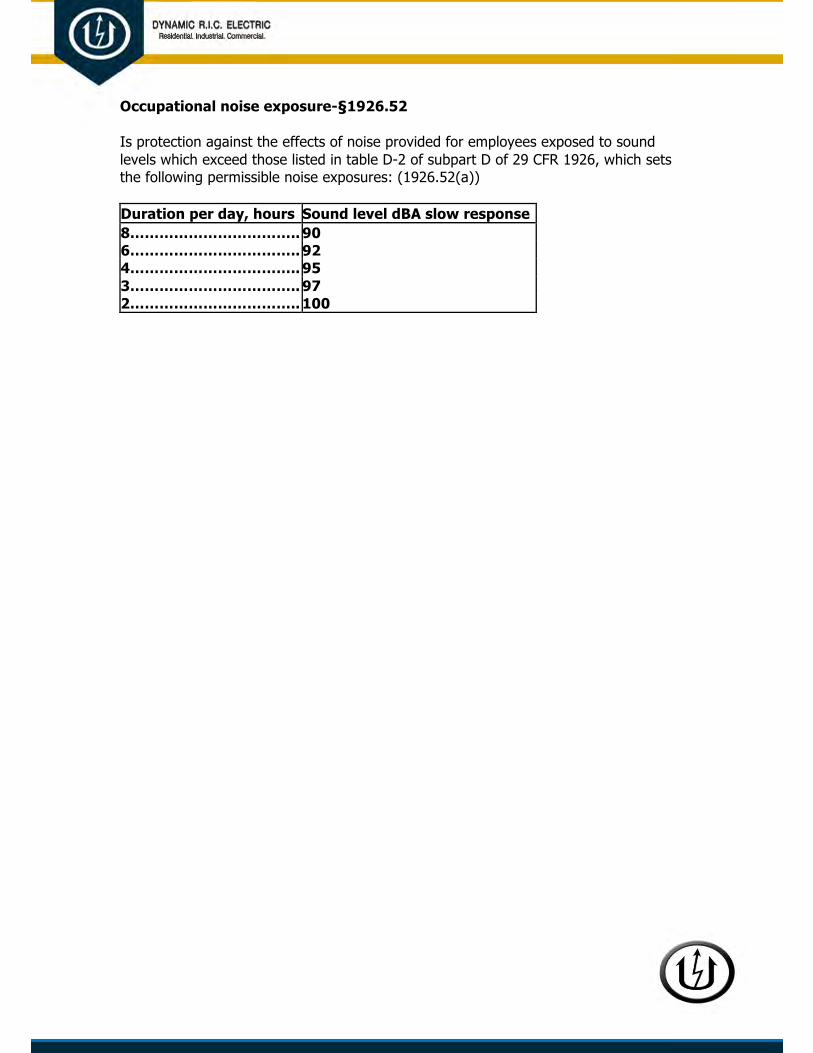
Occupational noise exposure-§1926.52
Is protection against the effects of noise provided for employees exposed to sound levels which exceed those listed in table D-2 of subpart D of 29 CFR 1926, which sets the following permissible noise exposures: (1926.52(a))
Duration per day, hours Sound level dBA slow response 8…………………………….. 90 6…………………………….. 92 4…………………………….. 95 3…………………………….. 97 2…………………………….. 100

1 ½…………………………. 102 1…………………………….. 105 ½……………………………. 110 ¼ or less………………….. 115
Hazard Communication-§1926.59/1910.1200
Is each container of hazardous chemicals in the workplace labeled, tagged or marked identifying the chemical that it contains? (1910.1200(f)(5)(i))
Is each container of hazardous chemicals labeled, tagged or marked with appropriate hazard warnings? (1910.1200(f)(5)(ii))
Is there a material safety data sheet for all chemicals used? (1910.1200(g)(1))
Are material safety data sheets readily accessible to employees in the work area during each work shift? (1910.1200(g)(8))
Are material safety data sheets made available upon request to designated representatives? (1910.1200(g)(11))
Is information provided to employees on operations in their work area where hazardous chemicals are present? (1910.1200(h)(2)(ii))
Is information provided to employees as to the location and availability of the written hazard communication program and material safety data sheets? (1910.1200(h)(2)(ii))
Does employee training include the physical and health hazards of the chemicals in the work area? (1910.1200(h)(3)(ii))
YES NO N/A
YES NO N/A
YES NO N/A
YES NO N/A
YES NO N/A
YES NO N/A
YES NO N/A
YES NO N/A

Personal protective and life saving equipment
Head protection-§1926.100
Are employees protected by hard hats while working in areas where there is a possible danger of head injury from impact, falling or flying objects, or electrical shock and burns? (1926.100(a))
Hearing protection-§1926.101
Are ear protection devices provided and used when it is not feasible to reduce noise levels or duration of exposures to those specified in table D-2, Permissible Exposure, in 29 CFR 1926.52? (1926.101(a))
Eye and face protection-§1926.102
Is eye and face protective equipment used when machines or operations present potential eye or face injury? (1926.102(a)(1))
Safety belts, lifelines, and lanyards-§1926.104 p Are lifelines secured above the point of operation to an anchorage or structural
YES NO N/A
member capable of supporting a minimum-dead weight of 5,400 pounds? (1926.104(b)) p Are safety belt lanyards a minimum of ½ inch nylon, or equivalent? (1926.104(d)) YES NO N/A p Are safety belt lanyards no longer than 6 feet and have a nominal breaking YES NO N/A strength of 5,400 lbs.? (1926.104(d))
Fire protection and prevention
Fire protection-§1926.150
Is access to all available fire equipment maintained at all times? (1926.150(a)(2))
Is firefighting equipment in a conspicuous location? (1926.150(a)(3))
Is firefighting equipment periodically inspected and if defective immediately replaced? (1926.150(a)(4))
Is a fire extinguisher, rated not less than 2A, provided for each 3,000 square feet of the protected building area, or major fraction thereof? (1926.150(c)(1)(i))
Does travel distance from any point of the protected area to the nearest fire extinguisher exceed 100 feet? (1926.150(c)(1)(i))

Is there at least one fire extinguisher, rated not less than 2A located on each floor? (1926.150(c)(1)(iv))
Is there at least one fire extinguisher located adjacent to stairways on each floor of a multistory building? (1926.150(c)(1)(iv))
Is there a fire extinguisher, rated not less than 10B provided within 50 feet from areas where there are more than 5 gallons of flammable or combustible liquids or
5 lbs. of flammable gas are being used on the jobsite (not applicable to integral fuel tanks of motor vehicles)?
Fire prevention-§1926.151 p Is smoking prohibited at or in the vicinity of operations which constitute a fire YES NO N/A hazard, and is “No Smoking or Open Flame” conspicuously posted? (1926.151(a)(3)) p Is portable fire extinguishing equipment, suitable for the fire hazards involved, YES NO N/A provided at convenient conspicuously accessible locations in the yard area? (fire extinguishers rated not less than 2A must be placed so that max travel distance will not exceed 100 feet) (1926.151(c)(6))
p Does indoor storage obstruct or adversely affect the means of exit? YES NO N/A (1926.151(d)(1))
Flammable and combustible liquids-§1926.152 p Are approved containers and portable tanks used for the storage and handling of YES NO N/A flammable and combustible liquids? (1926.152(a)(1)) p Are flammable or combustible liquids kept clear of exits, stairways and other areas YES NO N/A normally used for safe passage of people? (1926.152(a)(2) p Are flammable liquids kept in closed containers when not actually in use? YES NO N/A (1926.152(f)(1))

Signs, signals, and barricades
Accident prevention signs and tags-§1926.200
p Are required signs and symbols visible when work is being performed? YES NO N/A (1926.200(a))
p Are required signs and symbols removed or covered promptly when thehazard no YES NO N/A longer exists? (1926.200(a))
Tool, hand and power
General requirements-§1926.300
Are hand tools, power tools, or similar equipment maintained in a safe condition? (1926.300(a))
Are power actuated tools, designed to accommodate guards, equipped with the guards when in use? (1926.300(b)(1))
Are moving parts of equipment that are exposed to contact by employees or which otherwise create a hazard guarded? (1926.300(b)(2))
Hand tools-§1926.301
Are impact tools free of mushroomed heads? (1926.301(c))
Are wooden handles of tools free of splinters or cracks and tight in the tool? (1926.301(d))
Are the noncurrent-carrying metal parts of electrical power operated hand tools grounded or of the double-insulated type? (1926.302(a)(1))
Are pneumatic power tools secured to the hose or whip by some positive means to prevent the tool from becoming accidentally disconnected? (1926.302(b)(1))
YES NO N/A
YES NO N/A
YES NO N/A
YES NO N/A
YES NO N/A
YES NO N/A
YES NO N/A

Are safety clips or retainers securely installed or maintained on pneumatic impact (percussion) tools to prevent attachments from being accidentally expelled? (1926.302(b)(2))
Are powder-actuated tools operated by employees who have not been trained in the operation of the particular tool in use? (1926.302(e)(1))
Are loaded powder actuated tools left unattended? (1926.302(e)(6))
YES NO N/A
YES NO N/A
YES NO N/A
Welding and cutting
Gas welding and cutting-§1926.350
Are valve protection caps in place and secured on compressed gas cylinders? (1926.350(a)(5))
Are compressed gas cylinders that are being transported by powered vehicles secured in a vertical position? (1926.350(a)(4))
Are compressed gas cylinders moved without being secured on a special carrier intended for this purpose, and do they have the regulators removed and valve protection caps put in place? (1926.350(a)(6))
YES NO N/A
YES NO N/A
YES NO N/A
Is a suitable cylinder truck, chain, or other steadying device used to keep compressed gas cylinders from being knocked over while in use? (1926.350(a)(7))
Are compressed gas cylinder valves closed when work is finished, when cylinders are empty, and when the cylinders are being moved? (1926.350(a)(8))
Are compressed gas cylinders secured in an upright position? (1926.350(a)(9))
Are compressed gas cylinders kept far enough away from the actual welding or cutting operation so that sparks, hot slag, or flame will not reach them? (1926.350(b)(1))
YES NO N/A
YES NO N/A
YES NO N/A
YES NO N/A
p Are fire resistant shields provided when it is impractical to keep compressed gas YES NO N/A cylinders far enough away from actual welding or cutting operations so that sparks, hot slag, or flame will not reach them? (1926.350(b)(1)) p Are fuel gas cylinders placed with the valve end up while in use? (1926.350(b)(3)) YES NO N/A p When a special wrench is required to close the valve on fuel gas cylinders; is it left YES NO N/A in position on the stem of the valve while the cylinders are in use? (1926.350(d)(2)) p Are defective hoses carrying gases or substances, which could ignite or enter YES NO N/A

into combustion or be in any way harmful to employees removed from service? (1926.350(f)(3)) p Is gas-welding equipment kept clear of passageways, ladders, and stairs? YES NO N/A (1926.350(f)(7))

p Are oxygen cylinders in storage separated from fuel-gas cylinders, reserve stocks YES NO N/A of carbides, and highly combustible materials (especially oil or grease) by a minimum distance of 20 feet or by a noncombustible barrier at least 5 feet high having a fire- resistance rating of at least ½ hour, as specified in Section 3.2.4.3, American National Standards Institute 749.1-1967? (1926.350(a)(10))
Arc welding and cutting-§1926.351 p Are current carrying parts of manual electrode holders passing through the YES NO N/A gripping portion or the outer surfaces of the jaws fully insulated against the maximum voltage encountered to ground? (1926.351(a)(2)) p Are welding cables in use free from improper repair or splices for a minimum YES NO N/A distance of 10 feet from the cable end to which the electrode holder is connected? (1926.351(b)(2))
Are frames of arc welding or cutting machines grounded? (1926.351(c)(5))
Do noncombustible or flameproof screens to protect employees and other persons working in the vicinity from the direct rays of the arc shield arc welding or cutting operations? (1926.351(e))
Fire prevention-§1926.352
Is suitable fire extinguishing equipment immediately available in work areas where welding, cutting, or heating is being performed? (1926.352(d))
Is fire extinguishing equipment that is available in work areas where welding, cutting or heating is being performed maintained in a state of readiness for instant use? (1926.352(e))
Ventilation and protection in welding, cutting, and heating-§1926.353
Are employees who perform welding, cutting, or heating protected by suitable eye protective equipment? (1926.353(e)(2))
Are employees who perform inert-gas metal-arc welding on stainless steel protected against dangerous concentrations of nitrogen dioxide? (1926.353(d)(1)(iv))
YES NO N/A
YES NO N/A
YES NO N/A
YES NO N/A
YES NO N/A
YES NO N/A
p Is suitable mechanical ventilation or respiratory protective equipment provided YES NO N/A
during general welding, cutting or heating operations where, because of unusual physical or atmospheric conditions, an unsafe accumulation of contaminants

Electrical-Installation safety requirements
General requirements-§1926.403
p Are entrances to rooms and other guarded locations containing exposed live parts YES NO N/A operating at 600 volts, nominal or less, marked with conspicuous warning signs forbidding unqualified persons to enter? (1926.403(i)(2)(iii))
Wiring design and protection-§1926.404 p On a construction site where an assured equipment grounding program is not YES NO N/A utilized, do all 120-volt, single phase, 15-and 20-ampere receptacle outlets that
are not part of the permanent wiring of the building or structure have approved ground-fault circuit interrupters for personal protection? (1926.404(b)(1)(ii))
Wiring methods, components, and equipment for general use-§1926.405
Do temporary wiring feeders originate in a distribution center? (1926.405(a)(2)(ii)(A))
Are temporary wiring feeder conductors run as a multiconductor cord or cable assemblies or within raceways; or, where not subject to physical damage, run as open conductors on insulators not more than 10 feet apart? (1926.405(a)(2)(ii)(A))
YES NO N/A
YES NO N/A
p Are receptacles for uses other than temporary lighting prohibited from being YES NO N/A installed on branch circuits, which supply temporary lighting? (1926.405(a)(2)(ii)(C))
Are lamps used in temporary wiring for general illumination protected from accidental contact or breakage? (1926.405(a)(2)(ii)(E))
Is portable electric lighting used in wet and/or other conductive locations such as drums, tanks, and vessels operated at 12 volts or less, or protected by a ground-fault circuit interrupter? (1926.405(a)(2)(ii)(G))
YES NO N/A
YES NO N/A
p Are flexible cords and cables used for temporary wiring protected from damage? YES NO N/A (1926.405(a)(2)(ii)(I)) p Are extension cord sets used for temporary wiring with portable electric tools and YES NO N/A appliances the three-wire type? (1926.405(a)(2)(ii)(J)) p Are conductors entering boxes, cabinets, or fittings protected from abrasion, and YES NO N/A are openings through which conductors enter effectively closed? (1926.405(b)(1)) p Are unused openings in cabinets, boxes and fittings effectively closed? YES NO N/A (1926.405(b)(1))

p Are electrical panels, junction boxes, or fittings provided with covers? YES NO N/A (1926.405(b)(2))
p Do fixtures, lampholders, lamps, rosettes, or receptacles have no live parts YES NO N/A
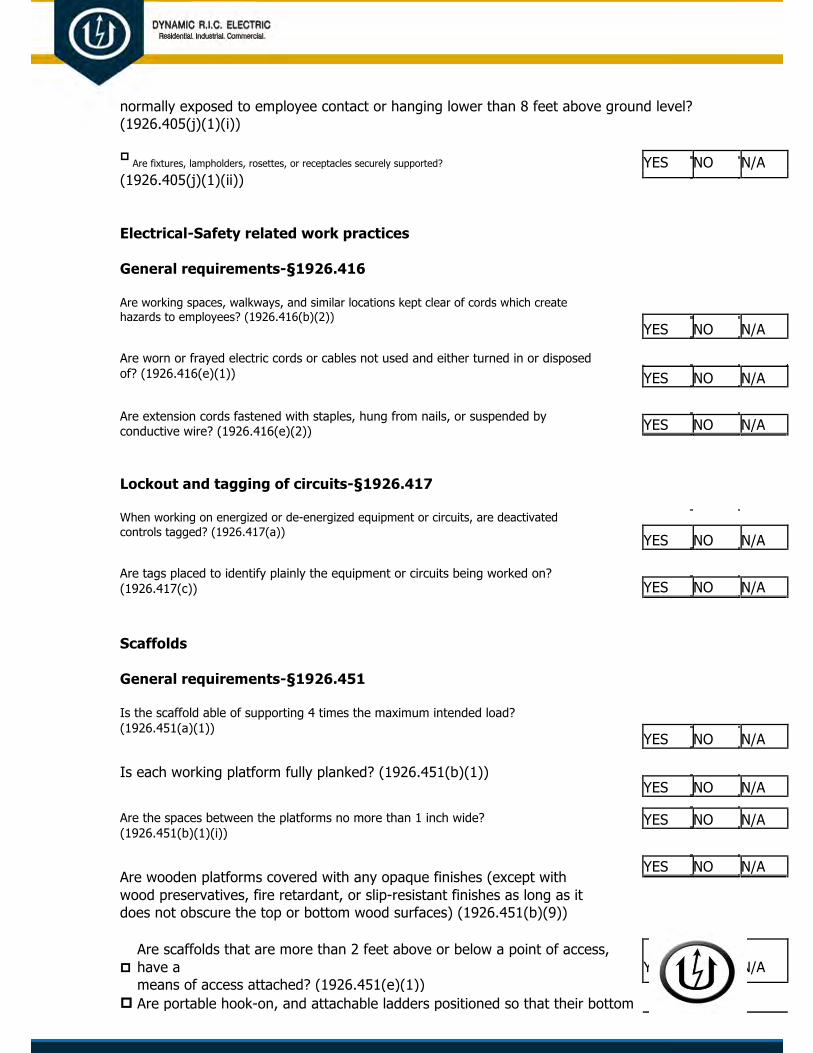
normally exposed to employee contact or hanging lower than 8 feet above ground level? (1926.405(j)(1)(i))
p Are fixtures, lampholders, rosettes, or receptacles securely supported? YES NO N/A (1926.405(j)(1)(ii))
Electrical-Safety related work practices
General requirements-§1926.416
Are working spaces, walkways, and similar locations kept clear of cords which create hazards to employees? (1926.416(b)(2))
Are worn or frayed electric cords or cables not used and either turned in or disposed of? (1926.416(e)(1))
Are extension cords fastened with staples, hung from nails, or suspended by conductive wire? (1926.416(e)(2))
Lockout and tagging of circuits-§1926.417
When working on energized or de-energized equipment or circuits, are deactivated controls tagged? (1926.417(a))
Are tags placed to identify plainly the equipment or circuits being worked on? (1926.417(c))
YES NO N/A
YES NO N/A
YES NO N/A
YES NO N/A
YES NO N/A
Scaffolds
General requirements-§1926.451
Is the scaffold able of supporting 4 times the maximum intended load? (1926.451(a)(1))
Is each working platform fully planked? (1926.451(b)(1))
Are the spaces between the platforms no more than 1 inch wide? (1926.451(b)(1)(i))
Are wooden platforms covered with any opaque finishes (except with wood preservatives, fire retardant, or slip-resistant finishes as long as it does not obscure the top or bottom wood surfaces) (1926.451(b)(9))
YES NO N/A
YES NO N/A
YES NO N/A
YES NO N/A
p
Are scaffolds that are more than 2 feet above or below a point of access, have a YES NO N/A means of access attached? (1926.451(e)(1))
p Are portable hook-on, and attachable ladders positioned so that their bottom

rung YES NO N/A is not more than 24 inches above the scaffold support level? (1926.451(e)(2)(ii))

Is the spacing between the rungs not more than 16 ¾ inches? (1926.451(e)(2)(vi))
Are employees protected from falling when 10 feet or more above a lower level? (1926.451(g)(1))
Is the top rail of the guardrail system between 36 and 45 inches in height, and able to withstand at least 100 pounds of force directed downward or horizontal at any point? (1926.451(g)(4)(ii)&(vii))
YES NO N/A
YES NO N/A
YES NO N/A
p Are midrails located between the top rail and the platform and able to withstand a YES NO N/A force of at least 75 pounds directed downward or horizontal at any point? (1926.451(g)(4)(ix))
Is steel or plastic banding (which is prohibited) used as toprail or midrails? (1926.451(g)(4)(xiii))
If crossbracing is used, is the crossing point between 20 and 30 inches above the work platform for midrails, and between 38 and 48 inches above the working level for top rails? (1926.451(g)(4)(xv))
YES NO N/A
YES NO N/A
Are employees protected from falling objects? (1926.451(h)(1))
Are scaffold that are more than 10 feet above a lower level have toeboards? (1926.451(h)(2)(ii))
Are toeboards capable of withstanding a force of at least 50 pounds applied in any downward or horizontal direction? (1926.451(h)(4)(i))
Is the toeboard at least 3 ½ high from the top edge of the toeboard to the level of the walking and working surface and does not have more than ¼ inch clearance above the walking/working level? (1926.451(h)(4)(ii))
YES NO N/A
YES NO N/A
YES NO N/A
YES NO N/A
Fall protection
General requirements-§1926.501
Are employees protected from falling into holes 6 feet or more above a lower level? (1926.501(b)(4)(i))
Are wall openings which is 6 feet or more to a lower level protected by a guardrail system, personal fall arrest system or a safety net system? (1926.501(b)(14)
YES NO N/A
YES NO N/A
Material handing equipment
General requirements-§1926.602
p Is material handling equipment with rollover protective structures or adequate YES NO N/A canopy protection provided with seat belts? (1926.602(a)(2)(i))

p
Are bi-directional machines equipped with an operable horn, distinguishable from YES NO N/A the surrounding noise level? (1926.602(a)(9)(i))
p Does lifting and hauling equipment have the rated capacity clearly posted on the YES NO N/A vehicle so as to be clearly visible to the operator? (1926.602(c)(1)(i))
Power transmission and distribution
General requirements-§1926.950
Is electric equipment and/or lines considered energized until determined to be deenergized by tests or other appropriate methods or means? (1926.950(b)(2))
Is training provided, and are employees required to be knowledgeable and proficient in procedures involving emergency situations? (1926.950(e)(1)(i))
Tools and protective equipment-§1926.951
Are harnesses and lanyards worn and are other safeguards employed to protect employees working at elevated conditions? (1926.951(b)(1))
Mechanical equipment-§1926.952
Are aerial lift trucks grounded or barricaded and considered as energized equipment when working near energized lines or equipment? (1926.952(b)(2))
Grounding for protection of employees-§1926.954
Are bare wire communications conductors on power poles or structures treated as energized lines? (1926.954(c))
Are the ends of grounds, other than the ground ends, attached or removed by means of insulated tools or other suitable devices? (1926.954(e)(1))
YES NO N/A
YES NO N/A
YES NO N/A
YES NO N/A
YES NO N/A
YES NO N/A
Stairways and ladders
General requirements-§1926.1051
p
Are stairways and ladders provided at all personnel points of access where there is YES NO N/A a break in elevation of 19 inches or more, and no ramp, runway, sloped embankment, or personnel hoist provided? (1926.1051(a))
p If a building or structure has only one point of access between levels, is that

point YES NO N/A of access kept clear to permit free passage of employees? (1926.1051(a)(3))

Stairways-§1926.1052 p Are stairways that have four or more risers or rising more than 30 inches, YES NO N/A whichever is less, equipped with one handrail and one stairrail system along each unprotected side or edge? (1926.1052(c)(1))
Are unprotected sides and edges of stairway landings provided with guardrail systems meeting the criteria in Subpart M of 29 CFR 1926? (1926.1052(c)(12))
Ladders-§1926.1053
If portable ladders are used for access to an upper landing surface, do the ladder side rails extend at least 3 feet above the upper landing surface to which the ladder is used to gain access? (1926.1053(b)(1))
YES NO N/A
YES NO N/A

p
If, because of the ladders length, the ladder side rails do not extend to at least 3 YES NO N/A feet above the upper landing surface, is the ladder secured at its top to a rigid support, and is a grasping device, such as a grabrail, provided to assist employees in getting on and off of the ladder? (1926.1053(b)(1))
p Is the top or step of a stepladder used as a step? (1926.1053(b)(13)) YES NO N/A
Other comments:
_______________________________________________________________________________ _______________________________________________________________________________
_______________________________________________________________________________
_______________________________________________________________________________ _______________________________________________________________________________
_______________________________________________________________________________ _______________________________________________________________________________
_______________________________________________________________________________
Name and title of person conducting inspection: ____________________________________ ___
Signature: ___________________________________________ Date:_____ / _____ / _____

Incident Investigation (multiple uses)
INCIDENT INVESTIGATION FORM
Checkone: Injury Incident Both injury and incident Vehicle Close call / near hit
1. SUPERVISOR CONTACT INFORMATION
a. Project Manager/ Supervisor / Investigator b. Title: c. Dept.: d. Phone: e. Ext.:
f. Place / g. Date of incident: h. Time of incident: (use i. Date and time of first knowledge of j. Creation date of this report location (mm/dd/yy) 24 hour time) incident (if different than incident time):
k. Subcontractor involved? If yes, name and contact information
2. INJURED PARTY/DRIVERa. If no injury, b. Injured party / driver name: c. Injured party / driver contact information:check box and skip
this section.
No injury
Injury description:
3. WITNESSES AND/OR WITNESS STATEMENTa. Witnesses b. Witness statement Yes (nameandcontact attached? information) No a. Witnesses b. Witness statement Yes (nameandcontact attached?information) No
4. PROPERTY DAMAGEa. List property / material damaged (usecontrolnumbersifavailable): b. Nature of damage:
c. Object / substance inflicting damage: d. Approximate cost:

5. THE INCIDENT
Causal analysis type:
a. Briefly describe what happened (descriptionofoccurrence) Investigate scene of incident or conditions. Describe who was involved, when and where the incident happened, what happened, and how. Attach photos if available.
b. Why did it happen? (descriptionofcause) What actually caused the illness, injury, or incident?
c. What did you do in response? What were the results? List actions taken and results. (Donotentercorrectiveactions.SeeSection6.)
d. What should be done to prevent a recurrence? Brief final evaluation and lessons learned Use descriptive constructive statements (such as “worker shouldwear safety glasses”; “worker needs training in lifting techniques”; “a ladder should have been used”). Primary focus should be on engineering controls, where possible.

6. CORRECTIVE ACTIONS TRACKING SYSTEM ITEMS
List action(s) that have or will be taken to prevent a recurrence. There should be a Actual Target completion corrective action for each item identified in 5.d. above. Add additional lines as needed.
By whom completion date date
1.
2.
3.
7. WORK PLANNING AND CONTROL AUTHORIZATION REVIEW
a. Is there a, JSA, MOP or SOP that authorized the task being performed when the injury or incident occurred?
Ifyes,reviewthedocument(s),answerthefollowingquestions,andattachacopytothisreport.
Ifno,pleaseexplainwherehazardsandcontrolsweredocumented,andhowtheworkerwasauthorizedtoperformwork.
Yes
No
b. Was person involved in incident in full compliance with all training requirements? If not, please explain.
Yes
No
c. Were hazards sufficiently identified? If not, please explain.
Yes
No
d. Were identified controls adequate? If not, please explain.
Yes
No
e. Were the identified controls implemented? If not, please explain.
Yes
No
8. WORK PLANNING AND CONTROL RELEASE REVIEW
a. Is there evidence that the person involved in the incident was released to perform task(s) on date of incident? Yes • If yes, answer the following questions and attach a copy of this report. If no,pleaseexplain.
No
b. Was the person performing task(s) in accordance with work release? If no, please explain.
Yes
No
c. How were area hazards, changing conditions, and/or potential interference with other workers, etc. communicated to person?

AUTHORIZING SIGNATURES
Investigation completed by: Date
a.
Reviewed by ESH coordinator and/or department ESH coordinator: Date
b.
Accident Investigation Report
ACCIDENT INVESTIGATION REPORT
ACCIDENT DATE AM
I. COMPANY INFORMATION
ACCIDENT TIME PM
Name Telephone No. Fax
Address Accident Address (if different than above)
Investigator Telephone No. Fax
II. EMPLOYEE INFORMATIONName Social Security No. Sex Age
Home Address
Department Job Title
Employment Status Full Time Part Time Temporary Other
Length of Employment Less than 1 mo.1 - 5 mos. 6 mos. to 5 yrs. More than 5 yrs.
Time in Occupation at Time of Acciden tLess than 1 mo. 1 - 5 mos. 6 mos. to 5 yrs. More than 5 yrs.
III. INJURY INFORMATIONPerson Reported To Date Reported
Nature of Injury and Part of Body
Employee’s Specific Task and Activity at Time of Accident

Working Alone Working with assigned group Supervised Not Supervised
SEVERITY OF INJURY ACCIDENT REPORT NUMBERS AND NAMES OF OTHERS INJURED Fatality 1.
Lost work days - days away from work 2.
Days of restricted activity or job transfer 3.
Medical treatment 4.
First aid 5.
Other, specify 6.
NAME OF PHYSICIAN NAME AND ADDRESS OF HOSPITAL / CLINIC
IV. WITNESSES
Name Telephone Number
Name Telephone Number
Name Telephone Number
Name Telephone Number0

V. SCENE OF ACCIDENT INFORMATION
Specific Location
Describe How the Accident Occurred
Diagram any Specific Location Factors That Contributed to the Accident
Type of Equipment / Machinery Involved
Equipment / Machinery Placed 1. Out of Service Repaired (if involved) 2. Out of Service Repaired
3. Out of Service Repaired
V I . ACCIDENT SEQUENCE. Describe in order of occurrence the events leading to the accident and/or injury. Reconstruct the sequence of events that led to the accident.
Event #1
Event #2
Accident Event

VII. CAUSAL FACTORS. Describe events and conditions that contributed to the accident. Include information on worker,machinery and equipment, environment and management.
VIII. CORRECTIVE ACTIONS. Identify the factors listed above that can be corrected to prevent a reoccurrence of this typeof accident. Indicate the person responsible for making the change and project a target date for completion of the task.Use the diagram grid below to illustrate layout changes.
CAUSAL FACTOR ASSIGNMENT TARGET DATE RESPONSIBILITIES FOR COMPLETION
1.
2.
3.
4.
5.
6.
7.
8.
9.

IX. SUMMARY. Include comments that would promote a safe workplace environment and reduce anaccidents potential in the future based on review of the Causal Factors and implementation of CorrectiveActions.
If corrective action is required:
Approved by
Signature Date
Title
This Industrial Accident Investigation Report was prepared by:
Signature Date
Title Department

Underground Line-Cable Damage Report
Damage Information Reporting Tool - Field Form Part A – Who is Submitting This Information
Who is providing the information? Electric Engineer/Design Equipment Manufacturer
Insurance Liquid Pipeline Locator Natural Gas
One-Call Center Private Water Public Works Railroad
Road Builders State Regulator Telecommunications Unknown/Other
Name of the person providing the information:
Part B - Date and Location of Event
*Date of Event: (MM/DD/YYYY)
*State *County City Street address Nearest Intersection *Right of Way where event occurredCity Street State Highway County Road Interstate Highway Public-Other Private Business Private Land Owner Private Easement Pipeline Power /Transmission Line Dedicated Public Utility Easement Federal Land Railroad Data not collected Unknown/Other
Part C – Affected Facility Information *What type of facility operation was affected?
Cable Television Electric Natural Gas Liquid Pipeline Sewer (Sanitary Sewer)
Telecommunications Water Unknown/Other
*What type of facility was affected? Gathering Service/Drop Transmission Unknown/Other
Was the facility part of a joint trench? Yes No
Was the facility owner a member of One-Call Center? Yes No
Part D – Excavation Information *Type of Excavator
County Developer Farmer Municipality Occupant
State Utility Data not collected Unknown/Other *Type of Excavation Equipment
Backhoe/Trackhoe Boring Drilling Directional Drilling
Farm Equipment Grader/Scraper Hand Tools Milling Equipment
Probing Device Trencher Vacuum Equipment Data Not Collected Unknown/Other *Type of Work Performed
Cable Television Curb/Sidewalk Bldg. Construction Bldg. Demolition Driveway Electri Engineering/Survey Fencin
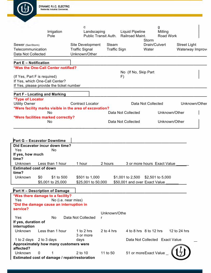
c g Irrigation Landscaping Liquid Pipeline Milling Pole Public Transit Auth. Railroad Maint. Road Work
Sewer (San/Storm) Site Development Steam Storm Drain/Culvert Street Light
Telecommunication Traffic Signal Traffic Sign Water Waterway ImprovementData Not Collected Unknown/Other
Part E – Notification *Was the One-Call Center notified?
(If Yes, Part F is required) No (If No, Skip Part F)
If Yes, which One-Call Center? If Yes, please provide the ticket number
Part F - Locating and Marking *Type of LocatorUtility Owner Contract Locator Data Not Collected Unknown/Other *Were facility marks visible in the area of excavation?
No Data Not Collected Unknown/Other *Were facilities marked correctly?
No Data Not Collected Unknown/Other
Part G – Excavator Downtime Did Excavator incur down time? Yes No If yes, how much time? Unknown Less than 1 hour 1 hour 2 hours 3 or more hours Exact Value ______
Estimated cost of down time? Unknown $0 $1 to 500 $501 to 1,000 $1,001 to 2,500 $2,501 to 5,000
$5,001 to 25,000 $25,001 to 50,000 $50,001 and over Exact Value ______
Part H – Description of Damage *Was there damage to a facility? Yes No (i.e. near miss)
*Did the damage cause an interruption inservice?
Yes No Data Not Collected Unknown/Other
If yes, duration of interruption Unknown Less than 1 hour 1 to 2 hrs 2 to 4 hrs 4 to 8 hrs 8 to 12 hrs 12 to 24 hrs
1 to 2 days 2 to 3 days 3 or more days Data Not Collected Exact Value _______
Approximately how many customers were affected? Unknown 0 1 2 to 10 11 to 50 51 or more Exact Value _______ Estimated cost of damage / repair/restoration

Unknown $0 $1 to 500 $501 to 1,000 $1,001 to 2,500 $2,501 to 5,000 $5,001 to 25,000 $25,001 to 50,000 $50,001 and over Exact Value ______
Number of people injured Unknown 0 1 2 to 9 10 to 19 20 to 49 50 to 99 100 or more Exact Value _______
Number of fatalities Unknown 0 1 2 to 9 10 to 19 20 to 49 50 to 99 100 or more Exact Value _______
* Part I – Description of the Root Cause *Please chooseone
Locating Practices Not Sufficient One-Call Notification Practices Not Sufficient
No notification made to the One-Call Center │ Facility could not be found or located
Notification to one-call center made, but not sufficient │ Facility marking or location not suffici
ent
Wrong information provided to One Call Center │ Facility was not located or marked │
│ Incorrect facility records/maps Excavation Practices Not Sufficient │ Miscellaneous Root Causes
Failure to maintain marks │ One-Call Center error
Failure to support exposed facilities │ Abandoned facility Failure to use hand tools where required │ Deteriorated facility
Failure to test-hole (pot-hole) │ Previous damage
Improper backfilling practices │ Data Not Collected
Failure to maintain clearance │ Other
Other insufficient excavation practices │

MISCELLANEOUS CHECKLISTS & FORMS
Bomb Threat Checklist
Bomb Threat Information Sheet
QUESTIONS TO ASK:
When is the bomb going to explode?
Where is it right now?
What does it look like?
What kind of bomb is it?
What will cause it to explode?
Did you place the bomb?
Why?
What is your address?
What is your name?
(Note if the caller is familiar with specifics of the jobsite)
Exact wording of the threat: (Ask the caller to repeat the message, if necessary)
Sex of caller: q M q F Race: Age:
Time of call: am/pm Date: Length of Call:
Caller’s Voice:
q Calm q Slow q Crying q Nasal q Deep q Read Message
q Angryq Rapid q Normal q Stutter q Ragged q Clearing Throat
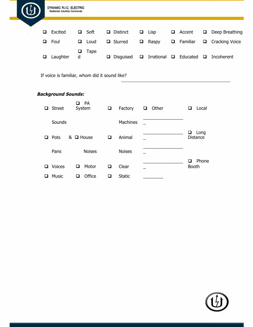
q Excited q Soft q Distinct q Lisp q Accent q Deep Breathing
q Foul q Loud q Slurred q Raspy q Familiar q Cracking Voice
q Laughterq Taped q Disguised q Irrational q Educated q Incoherent
If voice is familiar, whom did it sound like?
Background Sounds:
q Otherq Streetq PASystem q Factory q Local
Sounds Machines_________________
q Pots & q House q Animal_________________
q LongDistance
Pans Noises Noises_________________
q Voices q Motor q Clear_________________
q PhoneBooth
q Music q Office q Static ________

CONFINED SPACE ENTRY PERMIT
Date
Project
Project No
Location
Project Manager
Foreman
Permit space to be entered
Purpose of entry
Authorized duration of entry
permit
Personal protective
equipment to be used
Testing equipment used

Alarm systems
Communication equipment
Rescue equipment
Measures taken to isolate the permit space and
eliminate or control permit space hazards before entry

Hazards of permit space
Acceptable entry conditions
Rescue and E.M.S. services to be
called
INITIAL CONFINED SPACE AIR MONITORING
Air Monitor type:_______________________________
Serial No.:_____________________
Date:____________________ By who:_________________________________
Time Oxygen (O2) Combustible Carbon Hydrogen
Gas Monoxide Sulfide
PERIODIC CONFINED SPACE AIR MONITORING
Time Oxygen (O2) Combustible Carbon Hydrogen
Gas Monoxide Sulfide

Authorized entrants:_________________________________________________________
________________________________________________________________
Authorized attendants:_______________________________________________________
Entry Supervisor who originally authorized entry:_______________________
Signature:______________________________________________________
Current Entry
Supervisor:_______________________________________________________
Known
Hazards:_____________________________________________________
Additional
Comments:_______________________________________________________

______________________________________________________________
CROSBY CLAMPS
G-450 SS-450(Red-U-Bolt) (316 Stainless Steel)
WARNING
Failure to read, understand, and follow these instructions may cause death or serious injury.
Read and understand these instructions before using clips. Match the same size clip to the same size wire rope. Prepare wire rope end termination only as instructed.
Do not use with plastic coated wire rope.
Apply first load to test the assembly. This load should be of equal or greater weight than loads expected in use. Next, check and retighten nuts to recommended torque
(See Table 1, this page).

Critical Application Information
Efficiency ratings for wire rope end terminations are based upon the catalog breaking strength of wire rope. The efficiency rating of a properly prepared loop or thimble eye termination for clip sizes 1/8" through 7/8" is 80%. For sizes 1" thru 3-1/2" it is 90%. The number of clips shown (see Table 1 ) is based upon using RRL or RLL wire rope, 6 x 19 or 6 x 37 Class, FC or IWRC; IPS or XIP. If Seale construction or similar large outer wire type construction in the Installation Instructions
Step 1. Refer to Table 1 (below left) in following these instructions. Turn back specified amount of rope from thimble or loop. Apply first clip one base width from dead end of rope. Apply U-Bolt over dead end of wire rope – live end rests in saddle (Never saddle a dead horse!) Tighten nuts evenly, alternate from one nut to the other until reaching the recommended torque.
Step 2. When two clips are required, apply the second clip as near the loop or thimble as possible. Tighten nuts evenly, alternating until reaching the recommended torque. When more than two clips are required, apply the second clip as near the loop or thimble as possible, turn nuts on second clip firmly, but do not tighten. Proceed to Step 3.
Step 3. When three or more clips are required, space additional clips equally between first two - take up rope slack - tighten nuts on each U-Bolt evenly, alternating from one nut to the other until reaching recommended torque.
Figure 4. If a pulley (Sheave) is used, in place of a thimble add one additional clip. Clip spacing should be as shown.
Wire Rope Splicing Procedures:
Figure 5. The preferred method of splicing two wire ropes together is to use interlocking turnback eyes with himbles, using the recommended

The number of clips shown also applies to rotation - resistant RRL wire rope, 8 x 19 Class, IPS, XIP, sizes 1-1/2 inch and smaller; and to rotation-resistant RRL wire rope, 19 x 7 Class, IPS, XIP, sizes 1-3/4 inch and smaller.
For other classes of wire rope not mentioned above, we recommend contacting Crosby Engineering at (918) 834-4611 to ensure the desired efficiency rating.
For elevator, personnel hoist, and scaffold applications, refer to ANSI A17.1 and ANSI A10.4. These standards do not recommend U-Bolt style wire rope clip terminations. The style wire rope termination used for any application is the obligation of the user.
For OSHA (Construction) applications, see OSHA 1926.251.
Table 1
Clip Rope Minimum Amount of Rope Torque Size Size No. to Turn Back in (Inches) (Inches) of Clips in Inches Ft. Lbs.
1/8 1/8 2 3-1/4 4.5
3/16 3/16 2 3-3/4 7.5
1/4 1/4 2 4-3/4 15
5/16 5/16 2 5-1/4 30
3/8 3/8 2 6-1/2 45
7/16 7/16 2 7 65
1/2 1/2 3 11-1/2 65
9/16 9/16 3 12 95
5/8 5/8 3 12 95
3/4 3/4 4 18 130
7/8 7/8 4 19 225
1 1 5 26 225
1-1/8 1-1/8 6 34 225
1-1/4 1-1/4 7 44 360
1-3/8 1-3/8 7 44 360
1-1/2 1-1/2 8 54 360
1-5/8 1-5/8 8 58 430
1-3/4 1-3/4 8 61 590
2 2 8 71 750
2-1/4 2-1/4 8 73 750
2-1/2 2-1/2 9 84 750
2-3/4 2-3/4 10 100 750
3 3 10 106 1200
3-1/2 3-1/2 12 149 1200
If a pulley (sheave) is used for turning back the wire rope, add one additional clip.
If a greater number of clips are used than shown in the table, the amount of turnback should be increased proportionately.
*The tightening torque values shown are based upon the threads being clean, dry, and free of lubrication.

number of clips on each eye (See Figure 1).
Figure 6. An alternate method is to use twice the number of clips as used for a turnback termination. The rope ends are placed parallel to each other, overlapping by twice the turnback amount shown in the application instructions. The minimum number of clips should be installed on each dead end (See Figure 2). Spacing, installation torque, and other instructions still apply.
IMPORTANT
Apply first load to test the assembly. This load should be of equal or greater weight than loads expected in use.
Next, check and retighten nuts to recommended torque.
In accordance with good rigging and maintenance practices, the wire rope end termination should be inspected periodically for wear, abuse, and general adequacy.
G-429
WARNING
Failure to read, understand, and follow these instructions may cause death or serious injury. Read and understand these instructions before using clips. Match the same size clip to the same size wire rope. Do not mismatch Crosby clips with other manufacturers clips
Prepare wire rope end termination only as instructed.
Do not use with plastic coated wire rope.
Apply first load to test the assembly. This load should be of equal or greater weight than loads expected in use. Next, check and retighten nuts to recommended torque (See Table 1, this page).
Critical Application Information
Efficiency ratings for wire rope end terminations are based upon the catalog breaking strength of wire rope. The efficiency rating of a properly prepared loop or thimble eye termination for clip sizes 1/8" through 7/8" is 80%. For sizes 1" thru 3-1/2" it is 90%. The number of clips shown (see Table 1 ) is based upon using RRL or RLL wire rope, 6 x 19 or 6 x 37 Class, FC or IWRC; IPS or XIP. If Seale construction or similar large outer wire type construction in the

Installation Instructions
Step 1. Refer to Table 1 (below left) in following these instructions. Turn back specified amount of rope from thimble or loop. Apply first clip one base width from dead end of rope. Tighten nuts evenly, alternate from one nut to the other until reaching the recommended torque.
Step 2. When two clips are required, apply the second clip as near the loop or thimble as possible. Tighten nuts evenly, alternating until reaching the recommended torque. When more than two clips are required, apply the second clip as near the loop or thimble as possible, turn nuts on second clip firmly, but do not tighten. Proceed to Step 3.
Step 3. When three or more clips are required, space additional clips equally between first two - take up rope slack - tighten nuts on each Fist Grip evenly, alternating from one nut to the other until reaching recommended torque.
Figure 4. If a pulley (Sheave) is used, in place of a thimble add one additional Fist Grip. Fist Grip spacing should be as shown.
Wire Rope Splicing Procedures:
Figure 5. The preferred method of splicing two wire ropes together is to use interlocking turnback eyes with himbles, using the recommended number of clips on each eye (See Figure 1).

add one additional clip. If a pulley (sheave) is used for turning back the wire rope, add one additional clip. The number of clips shown also applies to rotation - resistant RRL wire rope, 8 x 19 Class, IPS, XIP, sizes 1-1/2 inch and smaller; and to rotation-resistant RRL wire rope, 19 x 7 Class, IPS, XIP, sizes 1-1/2 inch and smaller.
For other classes of wire rope not mentioned above, we recommend contacting Crosby Engineering at (918) 834-4611 to ensure the desired efficiency rating.
The style wire rope termination used for any application is the obligation of the user.
For OSHA (Construction) applications, see OSHA 1926.251.
Table 1
Clip Rope Minimum Amount of Rope *TorqueSize Size No. to Turn Back in(Inches) (Inches) of Clips in Inches Ft. Lbs.
3/16 3/16 2 4 30
1/4 1/4 2 4 30
5/16 5/16 2 5 30
3/8 3/8 2 5-1/4 45
7/16 7/16 2 6-1/2 65
1/2 1/2 3 11 65
9/16 9/16 3 12-3/4 130
5/8 5/8 3 13-1/2 130
3/4 3/4 3 16 225
7/8 7/8 4 26 225
1 1 5 37 225
1-1/8 1-1/8 5 41 360
1-1/4 1-1/4 6 55 360
1-3/8 1-3/8 6 62 500
1-1/2 1-1/2 7 78 500
If a pulley (sheave) is used for turning back the wire rope, add one additional clip. See Figure 4.
If a greater number of clips are used than show in the table, the amount of turnback should be increased proportionately.
* The tightening torque values shown are based upon the threads being clean, dry, and free of lubrication.
Figure 6. An alternate method is to use twice the number of clips as used for a turnback termination. The rope ends are placed parallel to each other, overlapping by twice the turnback amount shown in the application instructions. The minimum number of clips should be installed on each dead end (See Figure 2). Spacing, installation torque, and other instructions still apply.
IMPORTANT
Apply first load to test the assembly. This load should be of equal or greater weight than loads expected in use.
Next, check and retighten nuts to recommended torque.

In accordance with good rigging and maintenance practices, the wire rope end termination should be inspected periodically for wear, abuse, and general adequacy.
EEO Federal Project Checklist
FEDERALLY FUNDED PROJECT CHECKLIST Job Number
Project Name
DATE COMPLETED BY
ITEM DESCRIPTION LINK TO ITEM COMPLETED INITIALS
The Dynamic R.I.C. Electric Company EEO policy is displayed where
applicants can see it. This should be posted in the same area as the
1 other job posters
A Pre-Construction meeting has been attended (if we are a
subcontractor) where EEO has been discussed. Meeting minutes
2 have been obtained and are on file.
A Pre-Construction meeting has been held and EEO discussed with
all Dynamic R.I.C. Electric Company supervisors. Meeting minutes have been
3 generated and are kept on file.
A Pre-Construction meeting has been held with each of our
subcontractors (if applicable) and EEO has been discussed. Meeting
4 minutes have been generated and are kept on file.
Documentation of all solicitations of offers for subcontracts from
minority and female construction contractors and suppliers have
5 been maintained and kept on file.

Notice sent to Office of Federal Contral Compliance Programs
(OFCCP) for each Dynamic R.I.C. Electric Company subcontractor, where our
subcontract to them is greater than $10,000. Must occur within 10
6 working days of the award.
All persons involved in the hiring process have received EEO training
7 (annual requirement).
The letter to the local union office has been sent, requesting
8 assistance in meeting goals and obligations.
The letter to the NJATC has been sent, requesting assistance in
9 meeting goals and obligations.
10 An applicant log is being maintained on the jobsite.
Project Management has conducted a review with all supervisors on
their adherence to company EEO policy. Documentation of this
11 review is maintained and kept on file. (annual requirement)

Emergency-Contingency Plan Checklist M.21
(a) Purpose
The purpose of this policy is to supply our employees with outlined Emergency Action consistent with Occupational Safety and Health Administration (OSHA) Standard 29 CFR 1910.38.
In addition, the purpose is to:
Protect life and property.
Minimize the inconvenience and uncertainty of area residents and employees.
Establish in advance concepts, responsibilities, and procedures for the contingency operations.
Return to full operation as soon as possible.
19. Scope & Application
This program contains requirements for the implementation of an emergency action plan to be utilized on all projects or in individual office settings.

Project Emergency Response Plan
Project:
In the event of an emergency the following responsibilities are assigned:
Duties Primary Back-Up
Call 911
Notify Dynamic R.I.C. Electric Safety Department
Determine Emergency Services Needed
Direct Evacuation, secure the area
Overall Direction of Emergency Response Plan
Go to street to direct emergency vehicles
Take Photographs
Obtain witness statements, reports
Notify Owner
Accompany Injured parties to hospital

NOTES: q All communications during an emergency should be on (indicate radio channel or form of
communication). All other traffic on this channel should cease.
q No one is to re-enter secured areas until the all clear is given by the authorities (Fire Department, etc) and Dynamic R.I.C. Electric Company Project Management.
q In the event of an evacuation: All personnel must assemble in the (insert location). All crews must report to supervision. Supervision must report to Dynamic R.I.C. Electric Company immediately to ensure all personnel are accounted for. Refer to the Crisis Management Plan for further details.
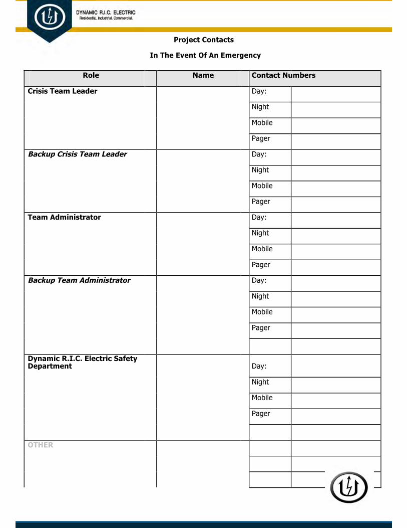
Project Contacts
In The Event Of An Emergency
Role Name Contact Numbers
Crisis Team Leader Day:
Night
Mobile
Pager
Backup Crisis Team Leader Day:
Night
Mobile
Pager
Team Administrator Day:
Night
Mobile
Pager
Backup Team Administrator Day:
Night
Mobile
Pager
Dynamic R.I.C. Electric Safety Department Day:
Night
Mobile
Pager
OTHER

OTHER

(c) Crisis Management Plan
1.0 Introduction
It is our goal to maintain the safest projects in the industry. Although we do everything we can to provide an Incident Free Environment, the possibility of a crisis occurring on one of our projects still exists. The Crisis Management Plan is designed to help project teams react to crisis situations should one arise.
These emergency response procedures outline the responsibilities of employees, including supervisors and management, in dealing with an emergency or crisis situation. These procedures outline the recommended steps to be taken to manage the response to various types of emergencies.
It is expected that these emergency response procedures be made familiar to every employee on the project through postings, discussion during the New Employee Orientation, Project Orientations, Job Startup Meetings and as a topic for Weekly Safety Meetings.
2.0 Responsibilities
2.1 Project Team Leader
The Project Team Leader is the center point for all emergency communications. This person ensures all team member positions are assigned and each person is aware of their responsibilities. The Project Team Leader advises and coordinates decisions with Senior Project Management and fills in for other team members as needed.
2.2 Team Administrator
The Team Administrator provides support to the crisis team, i.e., screening phone calls, making travel arrangements, providing clerical support and assisting families in the event of an injury or fatality. This person maintains a log of all emergency related inquiries received at the jobsite and ensures calls are returned by appropriate personnel in a timely fashion.

2.3 Dynamic R.I.C. Electric Company Project Management
Dynamic R.I.C. Electric Company Project Management should be knowledgeable of emergency response procedures and be prepared to assist those responding in the event of an emergency. Dynamic R.I.C. Electric Company Project Management should affirm that all new or transferred employees are aware of these procedures. Additionally, Dynamic R.I.C. Electric Company Project Management must verify that:
The emergency response procedures are implemented.
Dynamic R.I.C. Electric Company Safety Department is kept informed of the situation.
The safety of all personnel is maintained by means appropriate to the situation, i.e., work stoppage, evacuation, worker counts, maintenance of site security, etc.
Appropriate steps are taken to limit loss or damage to property or equipment and corrective actions, as applicable, are implemented as soon as possible.
Work is resumed when the emergency subsides and it is safe to do so.

EMERGENCY CONTINGENY PLAN
2.4 Supervision
During an emergency, supervision must assure worker safety and provide notification to Dynamic R.I.C. Electric Company Project Management that all personnel are accounted for.
2.5 Dynamic R.I.C. Electric Company Safety Department
Dynamic R.I.C. Electric Company Safety Department confirms that the applicable emergency response procedures are current and that personnel are aware of, and has knowledge of proper emergency reactions.
During and after an emergency, Dynamic R.I.C. Electric Company Safety Department is responsible for investigating, reporting and recommending future preventive action plans and reporting to the various governmental agencies and Dynamic R.I.C. Electric Company Project Leadership.
2.6 Workers Responsibilities
Workers are expected to participate in and follow emergency response procedures. Workers must respond immediately to instructions from supervision and emergency response agency personnel.
If workers are witnesses to an accident, they should (in order):
Immediately call out for first aid or other needed assistance.
Obtain access to radio or telephone and contact the appropriate emergency response contacts.
Send someone to the site access point to await the arrival of emergency response personnel and direct them to the appropriate area on-site.
Verify Supervision is immediately advised of the situation.
• Site Plan

A Site Plan indicating access gates, streets, telephones, fire fighting equipment, first aid equipment, evacuation routes and meeting points should be posted and/or available for review at the project.
This plan should also be reviewed with all employees and management during Employee Orientation, Job Startup Meetings and Weekly Safety Meetings.
4.0 First Aid and Medical Services
Dynamic R.I.C. Electric Company has contracted with the following facilities to provide medical care for all work-related injuries requiring medical aid:
Clinic Name & Address Telephone Hours Comments
This information is
to be determined
based on the location of the project

Dynamic R.I.C. Electric Company employees are to use the Dynamic R.I.C. Electric Company-designated medical facility. Project employees should use these designated facilities if at all possible. For projects out of town or in areas too far from these facilities for swift and efficient medical care, employees are to use the nearest medical facility Dynamic R.I.C. Electric Company Project Management will provide the name and location of these facilities.
A map outlining the project location, the location(s) of the nearest medical facilities, and the route to the facility should be posted. Employees of subcontractors should refer to their employer’s safety plan for this information.
5.0 Emergency Evacuation
Personnel will be informed of an evacuation by means of:
Word of mouth.
Telephone or radio contact.
Repeated air horn, whistle or other prearranged signal.
All affected personnel will be required to observe the following procedure in the event of an evacuation of the facility:
Stop all work activities.
If possible, shut down all equipment and energy sources.
All employees are to proceed to the nearest designated emergency meeting point using designated evacuation route(s).
Upon reaching the meeting point, employees must report to their Supervisor for a name check-off. Take necessary steps to keep non-essential persons away from the evacuated area.
Return to the facility and resume work only under the direction of Dynamic R.I.C. Electric Company Project Management.

6.0 Naturally Occurring Emergency Situations
Many urban centers offer weather watches or warnings. The following storm conditions fall into that category. When any of these storms is in the vicinity or is approaching the project, the following procedures should be observed.
6.1 Severe Lighting Storm
Lakes, sloughs or any open body of water should be avoided.
Tops of buildings, high lines, vessels or crane operation to be avoided.
Construction equipment should be shut down and personnel moved to a safe location until the storm has passed.
Vehicles to be pulled off the road and the 4-way flashers activated until the storm
has passed. 6.2 Tornado
Seek shelter below grade (staying inside structures is recommended but exterior doors and windows are to be avoided).
Operations of mobile crane to be suspended-boom should be laid down if time permits or the load line hooked to either the house or the structure at some low point. The equipment should be left and refuge taken in a shelter.

EMERGENCY CONTINGENY PLAN
Should shelter not be available, employees should proceed to low ground or a ditch and lie down with the head protected.
6.3 Blizzard
Employees working in remote areas where weather warnings are not applicable to the area should adopt the following procedures:
Awareness of prevailing weather conditions.
Dress to suit conditions; e.g. heavy-duty winter protection or survival equipment.
If possible, employees should work in pairs and conduct ongoing buddy checks for frostbite. Pedestrian travel routes should be known. Safety ropes should be erected as a guide.
Employees should not travel alone unnecessarily. Survival equipment should be carried.
6.4 Earthquake
Should the situation arise where there is structural collapse or the threat of imminent collapse due to an earthquake, the following general procedures should be followed:
Normal emergency assistance procedures.
The area of the earthquake should be secured. The nearest supervisors should be notified.
Lower booms on all crawler and mobile cranes. Cranes not capable of lower booms are permitted to weathervane per manufacturer’s recommendations. Ensure booms will not contact power lines, structures, etc.
People should be kept out of the area except for those rendering emergency aid.
All of the area utilities should be turned off as quickly as possible; providing it is safe to do so.

6.5 Landslide
Find shelter immediately.
Take action to preserve life and prevent injury.
6.6 Floods
Employees working in areas where flood conditions could occur should be prepared to take the appropriate actions when a weather warning or potential flood warning is issued:
If possible, post a watch (a signaling or warning device should be provided). Preparations should be made to leave on very short notice.
Only the required equipment or tools should be carried.
In the event of evacuation, all equipment, gas valves, etc. are to be shut down. Only dry electrical equipment is to be touched.
Avoid traveling through flooded areas, particularly at night when it is difficult to determine hidden dangers.
Employees should be aware of designated high ground safety areas, evacuation routes and the location of emergency equipment.

6.7 Hurricanes
The condition of the efforts of the Dynamic R.I.C. Electric on-site personnel and subcontractors shall be the responsibility of the Superintendent or Journeyman in-charge, who will direct the immediate evaluation of construction progress and specific hazards upon receipt of an alert.
The Superintendent or Journeyman in-charge shall direct and assist Dynamic R.I.C. Electric personnel in the protection of the work in progress and all equipment. If the General Contractor requests ride-out personnel, the project Manager shall respond to this request.
Secure materials, equipment and tools.
All construction trailer offices and storage units will be secured and abandoned. If required, all personnel will be provided with storm gear.
All vital records and equipment relating to construction shall be secured. All completed and accepted work will be secured as much as possible.
If practical, photographs shall be taken of critical work-in-place (i.e. switchgear, decorative lighting, control cabinets) upon warning of an emergency condition.
Conditions permitting, all equipment and vehicles will maintain full fuel tanks.
If ride-out personnel are required and authorized, these individuals will be provided with keys to all vehicles and equipment left on site.
The Superintendent or Journeyman in-charge will initiate a return to work program when so directed by the Project Manager.
p Other than Naturally Occurring Emergency Situations
Fire
Prudent safety practices indicate that "if you attempt to put out a fire in its incipient stages (the first 30 seconds), you stand a good chance of being successful". During the first 30 seconds, anyone discovering or becoming involved in a fire should follow emergency assistance procedures.
In the event a fire occurs on the project, supervisors should respond to the area and follow these procedures as applicable:
The fire is to be evaluated with regards to controlling it. Necessary evacuation steps should be taken.

Security measures should be established as necessary to keep non-essential people out and to safeguard records and equipment.
Turn off (do not unplug) all spark producing devices, i.e., electric motors, portable heaters, etc. Shut off all gases; if possible, remove high pressure cylinders from the area.
When directed to evacuate a building or facility under threat of fire, employees should observe the following points:
Permanent elevators are not to be used unless directed.
Lights to be left on, doors and windows closed but not locked.
Employees should stay as low as possible and try to keep out of the smoke (possibly toxic). Should clothes catch fire, the best thing to do is to drop and roll.
7.2 Bomb Threats
Dynamic R.I.C. Electric Company Project Management should be notified immediately of any bomb threat. As best as possible, preserve the evidence for law enforcement officials. Attempts should be made to obtain the following information (refer to Bomb Threat Information Sheet contained within this Appendix):
When is the bomb going to explode? Where is the bomb right now?
What kind of bomb is it?
What does the bomb look like? Why has the bomb been placed?
Also, the following information should be noted and recorded:
Time of day. Date of call.
Exact words of person making threat.
Age (child or adult) and sex of the caller. Speech pattern or accent.
Background noises.
If a suspected bomb or bomb threat is received by mail:
The letter, envelope or package is not to be handled.
Dynamic R.I.C. Electric Company Project Management is to be notified immediately.
7.3 Structure or Equipment
Should the situation arise where a structure has collapsed or equipment has been involved in an accident, the following general procedures should be followed:
The normal emergency assistance procedures should be followed. The area where the incident has occurred should be secured.
The nearest supervisors are to be notified.
People are to be kept out of the area except for those rendering medical assistance.
If necessary and safe to do so, area utilities are to be turned off as quickly as possible.
Attempts to clean up or repair should not be made until Dynamic R.I.C. Electric Company Project Management has given clearance.
7.4 Hazardous Substance Release or Spill
Immediately upon a release or a spill, steps should be taken to implement procedures for containment, control and clean up of the spill. These procedures should comprise the following basic steps:
The Material Safety Data Sheets (MSDS) are to be referred to for detailed procedures. The area is to be secured.

If the release is an airborne vapor spill, gas or a large uncontrollable spill of liquid, the local County Health Department or 911 dispatch is to be notified immediately. They will mobilize assistance and commence public evacuation in the immediate vicinity if necessary.
In most cases, clean-up procedures should start as soon as possible to prevent further spread of the substance into flowing water, ground water or sewer systems.
For small spills or spills of vehicle fluids, follow the guidelines and procedures set forth in the Material Safety Data Sheets (MSDS) for proper clean up and disposal.
7.5 Loss of Utilities
Should the loss of water occur, the following general procedures will apply:
Discontinue any current work procedures that require the use of water for safe work practices (i.e., asbestos abatement, core drilling, etc.)
Discontinue the use of all water.
Should the loss of electricity occur, the following general procedures apply:
Discontinue any current work procedures that require the use of electricity to operate equipment used as an engineering control for safe work practices.
Turn off any temporary equipment in the work area (i.e., negative air units, lighting, etc.) If work is to be continued, ensure adequate access/egress and task lighting is provided.
If an area blackout exists, contact the power company to obtain the latest estimates of service resumption and nature of all possible dangers at the site.
7.6 Security Issues
Should public demonstrations occur, the following general procedures apply:
Work on the jobsite can continue where not encumbered by the public demonstration; however, work in the immediate area should be stopped and all workers evacuated.
Notify police and fully cooperate with their instructions.

Allow only authorized personnel to enter the jobsite. Revoke all visitor passes and escort all visitors from the jobsite.
If necessary, utilize police or flag personnel to stop or detour traffic.
Should other in-progress emergency security issues occur, i.e., assault, theft, fights, attempted suicides and/or hostile persons, be prepared to give detailed of the incident to responding agencies, to include:
Direction of travel of person(s) involved if leaving the scene; Description of person(s) involved.

Team Leader Crisis Checklist
Gather all available information:
p Have the injured been cared for?p Is the scene of the incident safe and stable so other people are not injured?p Gather number and names of fatalities if any.p What happened?p Where did it happen?p When did it happen?p Whom is/was involved?p Who saw it happen?p What is the status of the emergency?p Is the job shutdown? Should it be?
Actions to take:
p Be sure someone has accompanied the injured to the medical treatment facility.p For a fatality, coordinate notification of spouse/family with the Safety Department.p Select someone to notify spouse/family of injured employee(s).p Notify the owner.p Post senior Dynamic R.I.C. Electric Company employees around the perimeter of the jobsite to
direct the media to the jobsite trailer.
p Secure a photographer and camera to photograph the scene of the incident.p Have someone route and handle telephone calls.p Notify OSHA if necessary (multiple injuries, fatality, etc).p Consult with Fire Department and/or Police Department if the surrounding areas and
neighborhoods should be informed of the incident.
p Check if additional information is available.p Should consultants (for example lawyers, a crisis management assistance company) be contacted
for emergency assistance?p Notify Team Administrator.p Secure and offer Post-Traumatic Stress counseling for employees who witnessed the incident.p Complete a post-emergency evaluation and lessons learned of the incident.
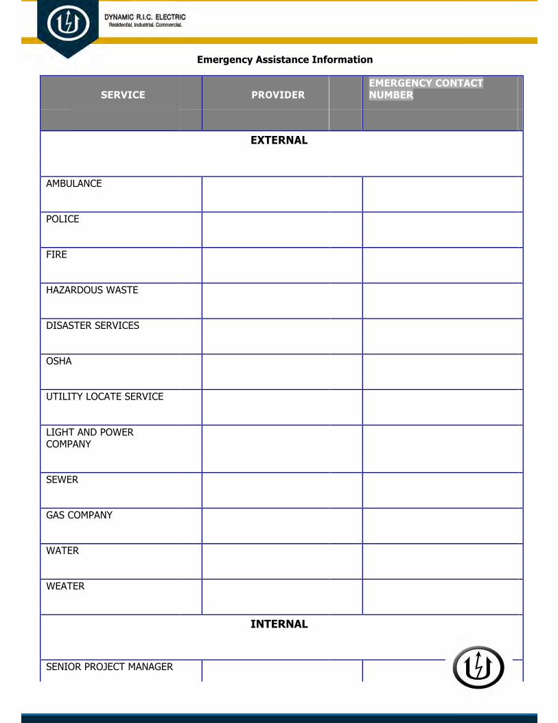
Emergency Assistance Information
SERVICE PROVIDER EMERGENCY CONTACT NUMBER
EXTERNAL
AMBULANCE
POLICE
FIRE
HAZARDOUS WASTE
DISASTER SERVICES
OSHA
UTILITY LOCATE SERVICE
LIGHT AND POWER COMPANY
SEWER
GAS COMPANY
WATER
WEATER
INTERNAL
SENIOR PROJECT MANAGER

PROJECT MANAGER
SAFETY MANAGER
PROJECT SUPERINTENDANT
PROJECT ENGINEER
PROJECT FOREMAN
PROJECT SAFETY
COORDINATOR

Bomb Threat Information Sheet QUESTIONS TO ASK:
When is the bomb going to explode?
Where is it right now?
What does it look like?
What kind of bomb is it?
What will cause it to explode?
Did you place the bomb?
Why?
What is your address?
What is your name?
(Note if the caller is familiar with specifics of the jobsite)
Exact wording of the threat: (Ask the caller to repeat the message, if necessary)
Sex of caller: q M q F Race: Age:
Time of call: am/pm Date: Length of Call:
Caller’s Voice:
q Calm q Slow q Crying q Nasal q Deep q Read Message
q Angryq Rapid q Normal q Stutter q Ragged q Clearing Throat
q Excited q Soft q Distinct q Lisp q Accent q Deep Breathing
q Foul q Loud q Slurred q Raspy q Familiar q Cracking Voice
q Laughterq Taped q Disguised q Irrational q Educated q Incoherent

If voice is familiar, whom did it sound like?
Background Sounds:
q Otherq Streetq PASystem q Factory q Local
Sounds Machines_________________
q Pots & q House q Animal_________________
q LongDistance
Pans Noises Noises_________________
q Voices q Motor q Clear_________________
q PhoneBooth
q Music q Office q Static ________

COMMENTS:

Excavation Inspection Checklist
Excavation Inspection Checklist Page 1 of 3
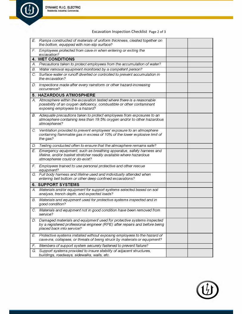
Excavation Inspection Checklist Page 2 of 3

Fall Protection Checklist
FALL PROTECTION- INSPECTION & MAINTENANCE Harness (and Body Belt) Inspection
To inspect your harness or body belt, perform the following procedures.
1) Webbing
Grasp the webbing with your hands 6 inches (152mm) to 8 inches (203mm) apart.
Bend the webbing in an inverted “U” as shown. The surface tension resulting makes damaged fibers or cuts easier to detect. Follow this procedure the entire length of the webbing, inspecting both sides of each strap. Look for frayed edges, broken fibers, pulled stitches, cuts, burns and chemical damage.
2) D-Rings/Back Pads
Check D-rings for distortion, cracks, breaks, and rough or sharp edges. The D-ring should pivot freely. Inspect for any unusual wear, frayed or cut fibers, or broken stitching of the D-ring attachments. Pads should also be inspected for cracks, excessive wear, or other signs of damage.
3) Buckles
Inspect for any unusual wear, frayed or cut fibers, or broken stitching of the buckle attachments.
4) Tongue Buckles/Grommets
Buckle tongues should be free of distortion in shape and motion. They should overlap the buckle frame and move freely back and forth in their socket. Roller should turn freely on frame. Check for distortion or sharp edges. Inspect for loose, distorted or broken grommets. Webbing should not have additional punched holes.

5) Friction and Mating Buckles
Inspect the buckle for distortion. The outer bars and center bars must be straight. Pay special attention to corners and attachment points at the center bar.
6) Quick-Connect Buckles
Inspect the buckle for distortion. The outer bars and center bars must be straight. Make sure dual-tab release mechanism is free of debris and engages properly.
7) Harness Fall Arrest Indicators
Inspect fall arrest indicators (located on the back D-ring pad) for signs of activation. Remove from service if broken or stretched between any of the four (4) pairs of arrows.

Lanyard Inspection
When inspecting lanyards, begin at one end and work to the opposite end, slowly rotating the lanyard so that the entire circumference is checked. Additionally, follow the procedures below.
1) Hardware
1. Snaps: Inspect closely for hook and eye distortions, cracks, corrosion,or pitted surfaces. The keeper (latch) should seat into the nose without binding and shouldnot be distorted or obstructed. The keeper spring should exert sufficient force to firmlyclose the keeper. Keeper locks must prevent the keeper from opening when the keepercloses.
2. Thimbles: The thimble must be firmly seated in the eye of the splice, andthe
splice should have no loose or cut strands. The edges of the thimble must be free of sharp edges, distortion, or cracks.
2) Wire Rope Lanyard
Always wear gloves when inspecting a wire rope lanyard; broken strands can cause injury. While rotating the wire rope lanyard, watch for cuts, frayed areas or unusual wearing patterns on the wire. Broken strands will separate from the body of the lanyard.
3) Web Lanyard
While bending webbing over a pipe or mandrel, observe each side of the webbed lanyard. This will reveal any cuts, snags or breaks. Swelling, discoloration, cracks and charring are obvious signs of chemical or heat damage. Observe closely for any breaks in stitching. Inspect lanyard warning flag for signs of activation. Titan tubular lanyards must be measured to determine activation.
4) Rope Lanyard
Rotate the rope lanyard while inspecting from end-to-end for any fuzzy, worn, broken or cut fibers. Weakened areas from extreme loads will appear as a noticeable change in original diameter. The

rope diameter should be uniform throughout, following a short break-in period.
5) Shock Absorber Pack
The outer portion of the pack should be examined for burn holes and tears. Stitching on areas where the pack is sewn to D-rings, belts or lanyards should be examined for loose strands, rips, deterioration or other signs of activation.
6) Shock-Absorbing Lanyard
Shock-absorbing lanyards should be examined as a web lanyard (described in item 3 above). However, also look for the warning flag or signs of deployment. If the flag has been activated, remove this shock-absorbing lanyard from service.
Self-Retracting Lifeline Inspection
1) Check Housing
Before every use, inspect the unit’s housing for loose fasteners and bent, cracked, distorted, worn, malfunctioning or damaged parts.
2) Lifeline
Test the lifeline retraction and tension by pulling out several feet of the lifeline and allow it to retract back into the unit. Always maintain a light tension on the lifeline as it retracts.
The lifeline should pull out freely and retract all the way back into the unit. Do not use the unit if the lifeline does not retract. The lifeline must be checked regularly for signs of damage. Inspect for cuts, burns, corrosion, kinks, frays or worn areas. Inspect any sewing (web lifelines) for loose, broken or damaged stitching.

3) Braking Mechanism
The braking mechanism can be tested by grasping the lifeline above the load indicator and applying a sharp steady pull downward which will engage the brakes. There should be no slippage of the lifeline while the brakes are engaged. Once tension is released, the brakes will disengage and the unit will return to the retractable mode. Do not use the unit if the brakes do not engage.
Check the hardware as directed in 1A under Lanyard Inspection. The snap hook load indicator is located in the swivel of the snap hook. The swivel eye will elongate and expose a red area when subjected to fall arresting forces. Do not use the unit if the load impact indicator has been activated.
4) Snap Hook
Check the snap hook to be sure that it operates freely, locks, and the swivel operates smoothly. Inspect the snap hook for any signs of damage to the keepers and any bent, cracked, or distorted components.
5) Anchorage Connection
Make sure the carabiner is properly seated and in the locked position between the attachment swivel/point on the device and the anchor point.
Cleaning
Basic care of all safety equipment will prolong the durable life of the unit and will contribute toward the performance of its vital safety function. Proper storage and maintenance after use are as important as cleansing the equipment of dirt, corrosives or contaminants. Storage areas should be clean, dry and free of exposure to fumes or corrosive elements.
1) Nylon or Polyester
Remove all surface dirt with a sponge dampened in plain water. Squeeze the sponge dry. Dip the sponge in a mild solution of water and commercial soap or detergent. Work up a thick lather with a vigorous back and forth motion; then wipe with a clean cloth. Hang freely to dry, but away from excessive heat.
2) Housing
Periodically clean the unit using a damp cloth and mild detergent. Towel dry.

3) Drying
Equipment should dry thoroughly without close exposure to heat, steam or long periods of sunlight.

PERSONAL FALL
ARREST SYSTEM Inspection Log
DYNAMIC R.I.C. ELECTRIC COMPANY
EMPLOYEE NAME HARNESS # MANF. DATE ISSUE DATE Color Code

Hot-Work Permit (not electrical)
Hot Work Permit
Date Issued
Issued By
Location of Hot Work
Type of Hot Work Welding - Cutting - Grinding - Other
EXPIRES Time___________ Date _____________ Job Description
Safety Requirements - required to be established & maintained the person issuing this permit has required the following safety Initials of Issuing precautions and indicated by his initials that the following circled
Authority items have been established prior to issuing this permit
No flammables/combustibles within 35 feet
Charged Extinguisher at work area
Fire Watch(es) briefed & stationed
Adequate ventilation established
Welding curtains or shields
Respirators used
Hot Work Personal Protective Equipment
Warning signs posted
Welding / cutting equipment inspected
Certified Welder
Surrounding equipment is Locked Out
No flammable / combustible gasses in area
Confined Space Entry Permit Issued
Access to work area controlled

Task Started Time__________ Date __________ Task Completed Time__________ Date __________ Fire Watch Secured Time__________ Date __________
Permit Ended Time__________ Date __________
Return Completed Permit to:
IMPACT Safety Card
MEMORANDUM FOR RECORD
To: New employee
Impact Safety Card
We believe every member of the Dynamic R.I.C. Electric team has an inherent right to a safe and healthy workplace. As such, we continually strive to create an environment that fosters safe behaviors. Therefore as a method to increase safety awareness on this project we will be using an “Impact Safety Card” which you will be assigned when you are hired. Any Dynamic R.I.C. Electric or General Contractor supervisor can ask for your card in the event you are witnessed doing something that compromises your safety or the safety of others. The first time the supervisor asks for the card, they will explain and annotate the violation on the card and return it to you. The second time they will do the same but will instead retain the card. The third time, since you will not have a card, you will be terminated for violation of safety protocol.

It is mandatory that you keep this card on you at all times. Failure to do so will result in termination. If this card becomes lost or damaged, you must immediately inform the project superintendent before the start of the work day/shift in order to receive a replacement.
This method does not change our current policy for IDLH violations. If you have any questions please notify your supervisor immediately.
Please sign below to acknowledge that you have read and understand this form.

IMPACT SAFETY CARD
Pulled by:___________________________________
Date:________________ Time:_________________
Employee Name:_____________________________ Reason:____________________________________
Supervisor Name:____________________________
Pulled by:___________________________________
Date:________________ Time:_________________
Issue Date:__________________________________ Reason:____________________________________
This Card must be presented to any
�PPE
�Fall Protection
�Lockout/Tagout
�Freelancing
�Vehicle Related
�Other (Specify)
supervisor upon request

Job Safety Analysis (JSA)
INSTRUCTIONS
PURPOSE
THIS FORM HAS BEEN PROVIDED FOR THE DYNAMIC R.I.C. ELECTRIC
COMPANY SUPERVISOR TO REVIEW:
TASKS TO BE COMPLETED BY HIS/HER CREW
HAZARDS ASSOCIATED WITH THESE TASKS
METHODS TO PROTECT EMPLOYEES FROM THESE HAZARDS
SCOPE
THIS FORM MUST BE COMPLETED EACH DAY PRIOR TO RELEAS- ING CREWS FOR WORK.
EMPLOYEE AKNOWLEDGEMENT
THIS PORTION MUST BE SIGNED BY EACH MEMBER OF THE CREW
AFTER THE SAFETY BRIEFING, AND BEFORE WORK MAY BEGIN. AT
THE END OF THE SHIFT, EMPLOYEES MUST PLACE THEIR INITI- TALS, INDICATING THAT THEY ARE LEAVING THE JOBSITE WITH- OUT ANY UNREPORTED INJURIES.

SECTION 1.
1. LIST THE TASKS EXPECTED TO BE COMPLETED
2. INDICATE THE RECOGNIZED HAZARDS ASSOCIATED WITH THE TASKS IN SECTION 1a.
3. INDICATE THE METHODS USED TO CONTROL THE HAZARDS LISTED IN SECTION 1b.
SECTION 2.
IDENTIFY ALL PRESCRIBED PERSONAL PROTECTIVE EQUIPMENT
THAT IS REQUIRED FOR USE AT ALL TIMES ON THIS PROJECT.
SECTION 3.
LIST ALL NECESSARY PERMITS THAT WILL BE REQUIRED FOR THE
WORK YOUR TEAM IS CONDUCTING.
SECTION 4.
CONDUCT A REVIEW AT THE END OF EACH SHIFT TO ENSURE OUR
WORK AREAS ARE SAFE AND SECURED.
SECTION 5.
SUPERVISORS MUST COMPLETE AND SIGN THE SUPERVISOR’S
SUMMARY SECTION AT THE END OF EACH SHIFT.

5. SUPERVISOR’S SUMMARY
INCIDENTS OR INJURIES
YES NO
WERE ANY INJURIES REPORTED TODAY? □ □ IF SO, PLEASE INDICATE WHEN AND TO WHOM THE INJURY WAS
REPORTED.
________________________________DATE:__________TIME:______
DID ANY UNPLANNED INCIDENTS OCCUR? □ □
IF SO, PLEASE INDICATE WHEN AND TO WHOM THE INCIDENT
WAS REPORTED.
________________________________DATE:__________TIME:______
DID YOUR CREW REPORT ANY NEAR MISSES? □ □
IF SO, PLEASE INDICATE WHEN AND TO WHOM THE NEAR MISS
WAS REPORTED.
________________________________DATE:__________TIME:______
PLEASE BRIEFLY DESCRIBE ANY DETAILS BELOW.
________________________________ ________________________________ ________________________________

________________________________
________________________________
MISCELLANEOUS
DO YOU HAVE ANY SAFETY SUGGESTIONS OR RECOMMENDA- TIONS?
________________________________ ________________________________ ________________________________ ________________________________ ________________________________
________________________________
JSA COMPLETED BY:
PRINTED NAME: ___________________________________________
SIGNATURE: ______________________________________________

JSA/JHA Form (with examples [Excel])
JOB SAFETY ANALYSIS TASK: PLACEMENT OF GENERATORS
DATE REVIEWED: REVIEWED BY:
TASK STEPS HAZARDS HAZARD CONTROL METHODS Determine Site Overhead Obstructions Ensure Area is Clear
Exhaust Entering Building Location of Vents and Intakes are at a suitable distance from generator exhaust
Accessability to Electrical Room Locate Electrical Room
Hook Boom to Generator
Pinch Points of Hook Wear Gloves
Lift Generator Off Truck Overhead Loads Personnel are kept clear of
load while operator is moving equipment
Placement of Personnel Operator verifies personnel are clear of load before lifting
Set Generator at Desired Placement of Personnel Operator verifies personnel are Location clear of load before setting to
ground
Pinch points Same as above
Unhook Generator from Boom Pinch Points Wear Gloves

JOB SAFETY ANALYSIS TASK: REMOVAL OF GENERATORS
DATE REVIEWED: REVIEWED BY:
TASK STEPS HAZARDS HAZARD CONTROL METHODS
Hook Boom to Generator Pinch Points of Hook Wear Gloves
Lift Generator Off Ground Overhead Loads Personnel are kept clear of load while operator is moving equipment
Placement of Personnel Operator verifies personnel are
clear of load before lifting
Set Generator on Truck Placement of Personnel Operator verifies personnel are
clear of load before setting onto truck
Pinch points Same as above
Unhook Generator from Boom Pinch Points Wear Gloves

JOB SAFETY ANALYSIS TASK: CONNECTING GENERATORS (GENERAL)
DATE REVIEWED: REVIEWED BY:
TASK STEPS HAZARDS HAZARD CONTROL
METHODS Cut Cable to Length Cut Fingers with Cable Cutters Ensure Fingers are Clear of
Tool
Pull Cable from Generator to Strains Use Proper Lifting & Pulling Attachment Point Techniques
Tripping Ensure Path is Clear
Ensure the Path is Lighted During Night Operations
Attach Cables to Both Ends Cut Fingers While Skinning Cut Away from Self Cable
Wear Gloves
Attach Warning Tape to Cables None None
Check Generator Voltage for Electrical Shock Use Proper Personal Protective
Proper Operation Equipment (Flash-rated Clothing, V-rated gloves, Hard Hat &Safety Glasses)
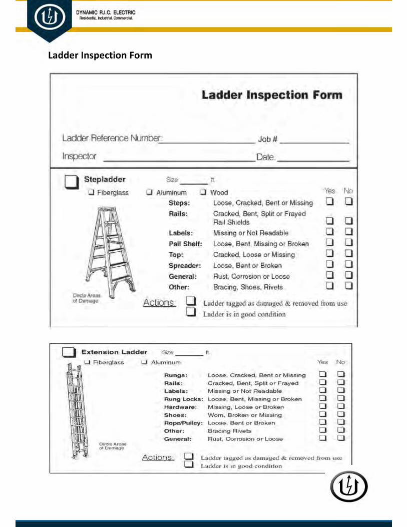
Ladder Inspection Form

Pre-Task Checklist

Pre-Task Checklist (fillable form)

Project Start-Up Checklist (Excel)


@) DYNAMIC R.I.C. ELECTRIC
Aeoda-t:W. h:lustriet O:wmotdU.
OSHA Safety & Health Standards Booklet
• This booklet is usually found at thefront of the Employee New Hire Packet.
• The employee keeps this booklet.
Employee Personal Information Form
• Everything on the top half of this formneeds to be filled out.
• Make sure they put their race, sex andemergency contact information.
• Make sure everything is legible.
Employee History Record
• This form should be filled out and signed by theemployee.
• The Yes or No questions are simply asking theemployee if they can perform the work that isdescribed.
• The answer we are looking for on all questions is"Yes" with the except
i
on of Driving a Company vehlde.
• If they answer "No" on any question then you needto explain the question to them to make sure thatthey understand the requirement.
• If they still insist on answering 'No" then you need to contact the office for further instructions.
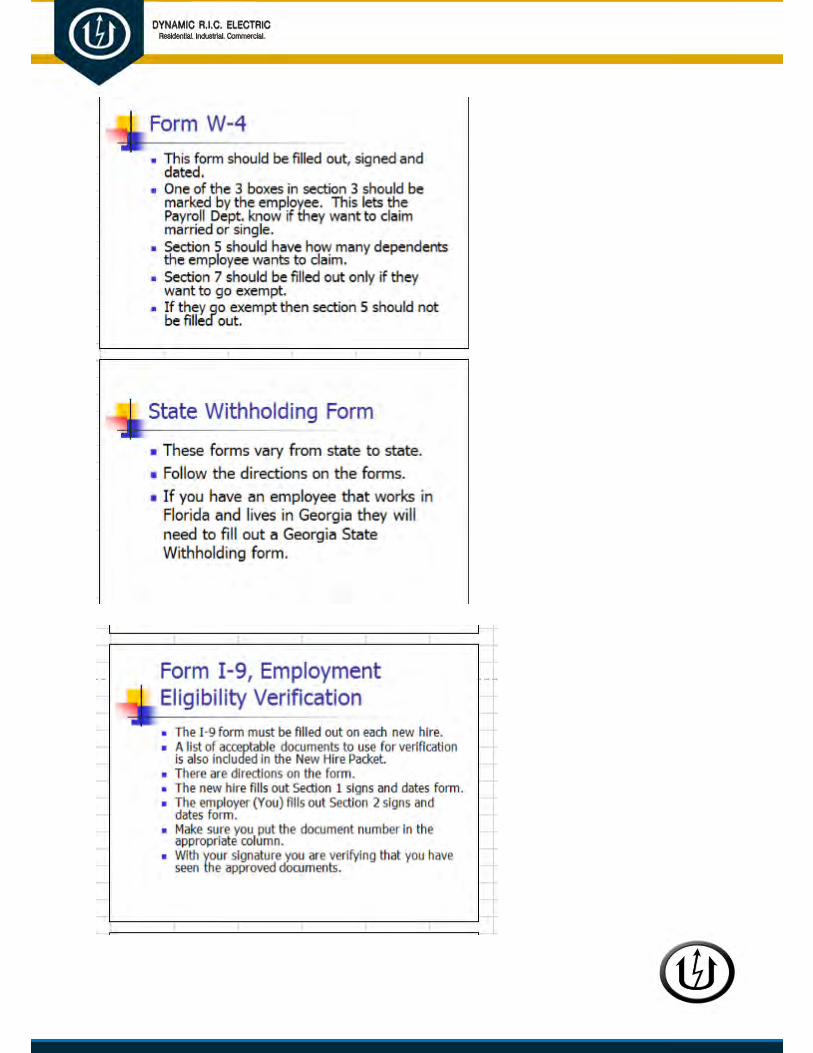


Rope Inspection Guideline
Rope Inspection and Retirement
There are basically three steps to consider in providing the longest possible service life, the safest conditions and long range economy for ropes:
Selection, Usage and Retirement.
The use of rope for any purpose subjects it to friction, bending and tension. All rope hardware, sheaves, rollers, capstans, cleats, as well as
knots are, in varying degrees, damaging to the rope. It is important to
understand that rope is a moving, working, strength member and even under the most ideal conditions
will lose strength during use in any application. Maximizing the safety of rope performance is directly related to how strength loss is managed and making sure ropes are retired from service before they can create a dangerous situation. Ropes are serious working tools and used properly will give consistent and reliable service. The cost of replacing a rope is extremely small when compared to the physical damage or personnel injury a worn out rope can cause.

1. SELECTION
Select the right rope for the job in the first place.
Selecting a rope involves evaluating a combination of factors. Some of these factors are straightforward, like comparing rope specifications. Others are less qualitative, like a preference for a specific color or how a rope feels in your hand. Cutting corners, reducing application factors, sizes or strengths on an initial purchase creates unnecessary replacements, potentially dangerous conditions and increases long term costs. Fiber and construction being equal, a larger rope will out-last a smaller rope because of the greater surface wear distribution. By the same token, a stronger rope will out-last a weaker one because it will be used at a lower percentage of its break strength with less chance of over-stressing.
STRENGTH: When given a choice between ropes, select the strongest of any given size. A load of
200 pounds represents 2% of the strength of a rope with a breaking strength of 10,000 pounds. The same load represents 4% of the strength of a rope that has a breaking strength of 5,000 pounds. The weaker rope is having to work harder and as a result will have to be retired sooner.
ELONGATION: It is well accepted that ropes with lower elongation under load will give you better load control, which is a big help at complicated job sites. However, a rope with lower elongation that is shock loaded can fail without warning even though it appears to be in good shape. Low elongating ropes should be selected with the highest possible strength. Twisted rope has lower strength and more stretch. Braided rope has higher strength and lower stretch.
FIRMNESS: Select ropes that are firm and round and hold their shape during use. Soft or mushy ropes will snag easily and abrade quickly causing accelerated strength loss. A loose or mushy rope will almost always have higher break strengths than a similar rope that is firm and holds its shape because the fibers are in a straighter line, which improves strength but compromises durability.
CONSTRUCTION AND ABRASION: Rope construction plays an important role in resistance to normal wear and abrasion. Braided ropes have a basically round, smooth construction that tends to flatten out somewhat on a bearing surface. This distributes the wear over a much greater area, as opposed to the crowns of a 3-strand or, to a lesser degree, on an 8-strand rope.
All ropes should be protected against sharp and abrasive surfaces. Wire ropes tend to score and gouge chocks and bitts creating cutting edges that can damage synthetic ropes. Weld beads on repaired capstans, fairleads, etc. are equally damaging unless
dressed down smoothly.

2. USAGE
Use rope properly: do not abuse or shock load it. Observe recommended usage factors for bending and work loads. Keep ropes clean and eliminate abrasion whenever possible.
WORKING LOADS: Working loads are the loads that a rope is subjected to in everyday activity. They are normally expressed as a percentage of new rope strength and should not exceed 20%. A point to remember is that a rope may be severely overloaded or shock loaded in use without breaking. However, damage and strength loss may have occurred without any visible indication. The next time the rope is used under normal working loads the acquired weakness can cause it to break. Do not blame the rope, it was simply overloaded and failed from what is known as fatigue.
BENDING: Any sharp bend in a rope under load decreases its strength substantially and may cause premature damage and failure. Sheave diameters on rotating sheave blocks should be 10 times the rope diameter for twisted ropes and eight times the rope diameter for braided ropes. The diameter on fixed pin terminations should be at least three times the rope diameter (i.e. the bending radius for 1/2" ropes should be 1-1/2").
KNOTS: While it is true that a knot reduces rope strength, it is also true that a knot is a convenient way to accomplish rope attachment. The strength loss is a result of the tight bends that occur
in the knot. With some knots, ropes can lose up to 50% of their strength. It is vital that the reduction in strength by the use of knots be taken into account when determining the size and strength of a rope to be used in an application. To avoid knot strength reduction, it is recommended that a rope be spliced according to the manufacturer’s instructions. Splice terminations are used in all our ropes to determine new and unused tensile strengths.
Therefore, whenever possible, spliced terminations should be used to maximize the rope strength for new and used ropes.
ROPE STORAGE: Keep your ropes as clean and dry as possible and store them in a coil away from heat sources.
SHOCK LOADS: Shock loads are simply a sudden change in tension from a state of relaxation or low load to one of high load. Any sudden load that exceeds the work load by more than 10% is considered a shock load. The further an object falls, the greater the impact. Synthetic fibers have a memory and retain the effects of being overloaded or shock loaded and can fail at a later time even though loaded within the work load range.

RECOMMENDED WORK
LOAD LIMIT:
For catalogued rope
CONSTRUCTION WORKING LOAD
Rope Construction Percentage of Strength Break
3-Strand 20%
8-Strand 20%
12-Strand 20%
Double Braid 20%
3. RETIREMENT
Retire rope from use when it has reached its discard point.
One of the most frequently asked questions is “When should I retire my rope?” The most obvious answer is before it breaks. But, without a thorough understanding of how to inspect it and knowing the load history, you are left making an educated guess. Unfortunately, there are no definitive rules nor industry guidelines to establish when a rope should be retired because there are so many variables that affect rope strength. Factors like load history, bending radius, abrasion, chemical exposure or some combination of those factors make retirement decisions difficult. Inspecting your rope should be a continuous process of observation before, during and after each use. In synthetic fiber ropes the amount of strength loss due to abrasion and/ or flexing is directly related to the amount of broken fiber in the rope’s cross section. After each use, look and feel along every inch of the rope length inspecting for abrasion, glossy or glazed areas, inconsistent diameter, discoloration and inconsistencies in texture and stiffness.
Understanding the Rope Design/Construction: It is first important to understand the design of the specific rope in use. Most ropes are designed to have features specifically tailored to their application. These features can lead to misconceptions during visual inspections. When a rope has a braided cover, it is only possible to visually inspect the cover (which, at best, carries only 50% of the load). Rope designs utilizing HMPE fibers will show initial rapid abrasion until the rope has a fuzzy appearance — this appearance actually acts as a protective layer.

DETERMINING THE AVERAGE CONDITION OF THE ROPE: The average condition of a rope can be an important factor in determining the rope’s retirement. To determine the average condition, walk the entire length of the rope and document its overall condition. Many ropes can be classified by the total amount of overall wear and cleanliness.
ABRASION:
When the rope is first put into service the outer filaments of the rope will quickly fuzz up (fig. 2). This is the result of these filaments breaking and this roughened surface actually forms a protective cushion and shield for the fibers underneath. This condition should stabilize, not progress.
If the surface roughness increases (fig. 3), excessive abrasion is taking place and strength is being lost. As a general rule for single braid ropes, when there is 25% or more wear from abrasion the rope should be retired from service. In other words, if 25% or more of the fiber is broken or worn away the rope should be removed from service. With 3-strand ropes, 10% or more wear is accepted as the retirement point.
LOCATE AREAS DEVIATING FROM AVERAGE:
Many times a rope will have areas that are routinely used around a bit, through a chock or buried on the winch drum. These areas typically have different wear patterns than the average condition of the rope. Pay close attention to these areas in the future and frequently examine them for rapid changes in appearance.
Look closely at both the inner and outer fibers. When either is worn the rope is obviously weakened. Open the strands and look for powdered fiber, which is one sign of internal wear. Estimate the internal wear to estimate total fiber abrasion.

If total fiber loss is 20%, then it is safe to assume that the rope has lost 20% of its strength as a result of abrasion.
Internal abrasion can be determined by pulling one strand away from the others and looking for powdered or broken fiber filaments (fig. 4 and fig. 5).
To determine the extent of outer fiber damage from abrasion, a single yarn in all abraded areas should be examined. The diameter of the abraded yarn should then be compared to a portion of the same yarn or an adjacent yarn of the same type that has been protected by the strand crossover area and is free from abrasion damage. (fig. 6).
It should be noted that comparing diameters of the yarns does not give an accurate measure of the retained strength. Since the strength should depend on the cross-sectional area of the yarn, a diameter difference alone will underestimate the true abrasion reduction. If the diameter of the abraded yarn is 1/2 the diameter of the internal yarn,
the strength of the abraded yarn is nearly 1/4 that of the internal yarn.
Determining the extent of fiber loss due to abrasion can be difficult. Since all the strands are twisted, the outer fibers, which are the most prone to abrasion damage, rotate through the rope’s length. Therefore on a single strand, the fibers that have been abraded on
one pick are not necessarily the fibers being abraded on the next. However, over a long distance, a single yarn could have the majority of fiber loss due to abrasion.
GLOSSY OR GLAZED AREAS:
Glossing or glazing can occur from two different mechanisms. The most common and relatively benign form of glossing or glazing on a rope is generally caused by compression (fig.7), which typically occurs when the rope is wound on the winch drum, around bitts or through chocks or staples. This form of glossing can be determined on
8- and 12-strand products by compressing the rope length wise forming a “bird cage”
(fig.8).
After numerous “bird cage” cycles the glossy region will become more pliable and begin to resemble normal rope. If the glazed section remains hardened, this could be a sign of heat damage. Heat damaged rope typically has more strength loss than the amount of melted fiber indicates. Fibers adjacent to the melted areas are probably damaged from excessive heat even though they appear normal. It is reasonable to assume that the melted fiber has damaged an equal amount of adjacent unmelted fiber.
INCONSISTENT DIAMETER:
Inspect for flat areas, bumps or lumps. This can indicate core or internal damage from overloading or shock loads and is usually sufficient reason to replace the rope.
DISCOLORATION:
With use, all ropes get dirty. Be on the lookout for areas of discoloration which could be caused by chemical contamination. Determine the cause of the discoloration and replace the rope if it is brittle or stiff.
INCONSISTENCY IN TEXTURE AND STIFFNESS:
Can indicate excessive dirt or grit embedded in the rope or shock load damage and is usually reason to replace the rope.
TEMPERATURE:
When using rope, friction can be your best friend or worst enemy if it is not managed properly. By definition, friction creates heat, the greater the friction the greater the heat buildup. Heat is an enemy to synthetic fiber and elevated temperatures can drastically reduce the strength and/or cause rope melt-through.

Charring point:
High temperatures can be achieved when surging rope on a capstan or drum end, checking ropes on bitts and running over stuck or non-rolling sheaves or rollers. Each rope’s construction and fiber type will yield a different coefficient of friction (reluctance to slip) in a new and used state. It is important to understand the operational demands and ensure the size, rope construction and fiber type be taken into account to minimize heat buildup.
Never let ropes under tension rub together or move relative to one another. Enough heat to melt the fibers can buildup and cause the rope to fail as quickly as if it had been cut with a knife.
Always be aware of areas of heat buildup and take steps to minimize it; under no circumstances let any rope come in contact with a steam line or any other hot surfaces.
The strength of a used rope can be determined by testing but the rope is destroyed in the process so the ability to determine the retirement point before it fails in service is essential. That ability is based on a combination of education in rope use and construction along with good judgment and experience.
The critical and melting temperatures for synthetic fibers are listed below:
Fiber Type Critical Temp. Melting Temp.
Polypropylene 250° F 330° F
HMPE 150° F 300° F
Technora 520° F 930° F*
Nylon 325° F 425 – 490° F
Polyester 350° F 480 – 500° F

Rope displaying original bulk.
Rope displaying 25% strand volume reduction from abrasion — rope should be retired from service.
Rope strands showing full volume.
Rope strands reduced by 25% abrasion. Pulled strands should be worked back into the rope so they won’t continue to snag and eventually cut.
cut strands:
compression:
MELTING OR GLAZING:

Scaffolding Inspection Checklist
Site Specific Safety Plan (boilerplate [Word])
SITE SPECIFIC SAFETY PLAN (SSSP)
Purpose The purpose of this site specific safety plan is to act as a companion to Dynamic R.I.C. Electric Company’s Safety Program and Policy. This plan illustrates safety issues specific to the xxxxxxxxxxxxxx project. General issues of safety are covered in the Dynamic R.I.C. Electric Company Safety Manual. Site Information and Location
Key Personnel The following are the key Dynamic R.I.C. Electric Company personnel for this project. A breakdown of their duties, as they apply to safety can be found in section 7 of this site specific safety plan. Project Manager Project Manager Assistant Project Manager/Safety Safety Coordinator Superintendent General Foreman Foreman
Scope of the Project The installation of the low voltage electrical power distribution system for the including switchgear, distribution panels, lighting panels, cable trays, grounding, single and multi-conductor cabling and Uninterruptable Power Supplies. Areas of installation include the
Site Access Site access will be through
Temporary Facilities Temporary facilities will include one main office trailer, four employee break areas and temporary sanitary facilities at each of these locations. There shall also be various storage containers (gang boxes) and company vehicles. The quantity of these items may vary. Health and Safety Responsibilities
The effectiveness and success of the safety program depends upon the active participation and cooperation of all employees. Duties and responsibilities of all employees under this policy are the following:
Safety Coordinator

Coordinate health and safety training for management and supervisors Coordinate and conduct weekly safety meetings Coordinate jobsite safety audits Maintain and revise the site specific safety plan as needed Maintain jobsite postings and notices required by law Instruct and train all persons within area of responsibility in job health and safety requirements Ensure the proper filing of paperwork relating to accidents Participate in post-accident investigations Maintain all records and reports related to this policy Implement Dynamic R.I.C. Electric Company’s safety program and policy Project Manager/Assistant Project Manager Direct and coordinate health and safety regulations related to his area of responsibility Ensure arrangements for prompt medical attention in case of serious injury have been provided for the project, to include transportation, communication, and emergency telephone numbers Instruct and train all persons within area of responsibility in job health and safety requirements Conduct weekly safety meetings Participate in post-accident investigations Assist in formulating policy matters Implement Dynamic R.I.C. Electric Company’s safety program and policy Superintendent Familiarize himself with health and safety regulations related to his area of responsibility Direct and coordinate health and safety activities within his area of responsibility Ensure all employees supervised use required personal protective equipment and safety devices Ensure that safety equipment is available, maintained, used, and stored correctly Instruct and train all persons within area of responsibility in job health and safety requirements Direct correction of unsafe conditions Conduct weekly safety meetings Participate in post-accident investigation Review all accidents/incidents with foremen and workers involved. Ensure corrective action is taken immediately to eliminate the cause of the accident Ensure that foremen are aware of and comply with requirements for safe practices Require all subcontractors to comply with health and safety regulations as well as Dynamic R.I.C. Electric Company’s safety program and policy Maintain copies of applicable programs and OSHA forms on site, in accordance with Dynamic R.I.C. Electric Company’s practice and policy Implement Dynamic R.I.C. Electric Company’s safety program and policy General Foreman/Foreman/Frontline Supervisor Be familiar with, explain, and enforce health and safety regulations that apply to company operations within his/her area of responsibility Direct and coordinate health and safety activities within his/her area of responsibility Ensure that safety devices and proper PPE are used by persons under his/her supervision Instruct and train all persons within area of responsibility in job health and safety requirements, including, but not limited to, hazard recognition and avoidance, and require compliance by workers with the safety rules established Direct the correction of unsafe conditions Ensure that safety equipment is available, maintained, used, and stored correctly Participate in post-accident investigation Coordinate daily jobsite inspection

Implement Dynamic R.I.C. Electric Company’s safety program and policy All Employees Be familiar with and comply with proper health and safety practices Use the required safety devices and proper PPE Notify the supervisor immediately of unsafe conditions/acts, accidents and injuries Implement Dynamic R.I.C. Electric Company’s safety program and policy Subcontractors By contract, subcontractors shall comply with and ensure the compliance of their employees with the provisions of this policy as well as their own safety program. Failure to fulfill this requirement is a failure to meet the conditions of the subcontract.
Prohibited Conduct
Repairs Employees are prohibited from making repairs, alterations, or attachments to equipment in the field except by the permission of the safety director. Such repairs, alterations, or attachments shall be documented. Employees are prohibited from removing a guard, safety device, or appliance from equipment or machinery except to make repairs in conformance with the paragraph above. While making repairs, employees shall use appropriate lockout/tagout procedures. When the repairs are complete, the guard, safety device, or appliance shall be replaced immediately.
Equipment Use and Operation Equipment shall be used only for its intended use and as recommended by the manufacturer. Riding the load, hook, or sling is prohibited. Employees are prohibited from operating a vehicle in a reckless manner or at a speed greater than is reasonable and proper, with due regard for weather, traffic, character of roadway, load, type of vehicle, and any other conditions which may affect the safe operation of the vehicle. The vehicle must be kept under control at all times and special care shall be exercised when transporting personnel. Employees authorized to operate Dynamic R.I.C. Electric Company’s vehicles must sign and abide by the company’s Fleet Safety Policy. Employees may only ride equipment if there are seats or equal protection available for each person. Seatbelts shall be worn at all times while operating equipment with seats.
Personal Protective Equipment Employees must wear a hard hat, safety glasses, and safety work shoes while on the project. All PPE except work shoes shall be furnished by Dynamic R.I.C. Electric Company for its employees use. Employees will learn where to get PPE during their new hire orientation. Employees are responsible for wearing and maintaining required PPE. If an employee is unsure of the type of PPE required for a specific task or job, they should ask their supervisor. Policy Violations Employees who commit policy violations may be subject to Dynamic R.I.C. Electric Company’s Safety Discipline Policy, located in the safety manual and the employee handbook.
General Procedures
Training Training and education are necessary for the success of this policy. Employees will be

trained to recognize jobsite hazards and the procedures to follow to minimize these hazards. Training may consist of, but is not limited to, the following: Weekly jobsite safety meetings. Orientation training for new hires. Individual job/task training, which includes the applicable regulations/standards for the specific job/task.
Supervisors and management will receive ongoing safety training throughout the year as organized by the Safety Coordinator and as deemed necessary by the company owners. Such training shall include the maintenance of first aid and CPR cards.
Safety Meetings Weekly safety meetings shall be held on the jobsite. All employees and subcontractors are required to attend. The meetings may cover a range of safety-related topics. The format and content of the meeting is up to the discretion of the Superintendent.
Safety Inspections The Superintendent and Foreman shall conduct an initial safety inspection at the beginning of each project, following the “Jobsite Safety Checklist” that is included in the safety manual.
In addition, a weekly safety inspection of the jobsite will be conducted by Dynamic R.I.C. Electric Company employees, the employees of a subcontractor, or some combination thereof, with the inspection being rotated between all workers on the jobsite. Employees conducting the inspection shall utilize the safety inspection checklist. The list is intended as a guide. Any safety concern found during the inspection should be reported. If a worker is unclear about any item on the inspection checklist, a Dynamic R.I.C. Electric Company foreman or safety officer will be able to help them. If the area being inspected requires a competent person, the worker should do the inspection with the competent person. Also, if time allows, the foreman for the worker conducting the inspection is encouraged to walk through it with them.
Hazard Communication Dynamic R.I.C. Electric Company has developed a written hazard communication policy. It will be explained to each employee during their new hire orientation. This policy is located in the safety manual and is available upon request to the Superintendent. The purpose of the hazard communication policy is to provide information about chemical and physical agent hazards and the control of such hazards which includes container labeling, MSD sheets, physical agent data sheets, and training. The MSDS book is located in the jobsite trailer and will be covered during new hire orientation.
Job Hazard Analyses A job hazard analysis shall be developed that covers the major activities of construction, the hazards associated with these activities, and ways to mitigate these hazards. The job hazard analysis form is located in the safety manual.
Housekeeping Housekeeping is one of the most important factors for a safe jobsite. Site debris such as all-thread and MC cable shall be removed and disposed in approved containers. All other debris should be cleared

from work areas, passageways, and stairs. Excess materials should be stacked neatly, out of the way. Tools should be stored in approved containers so they are available for all employees to use.
Combustible scrap and debris should be removed at regular intervals during the course of construction. Containers with covers shall be provided for the collection and separation of waste, trash, oily and used rags, and other such refuse, which shall be removed safely and on a regular basis.
Electrical Safety Electrical safety may consist of, but is not limited to, the following: Live electrical parts shall be guarded against accidental contact by cabinets, enclosure, location, or guarding. All receptacles which are not part of the permanent wiring of the building will be equipped with GFCI receptacles at the temporary service drop. Extension cords will be kept in safe, working condition. All lamps for general illumination will have the bulbs protected against breakage. All light sockets shall be filled with a working bulb. Employees will not work in such close (able to contact) proximity to any part of an electric power circuit unless the circuit is de-energized, grounded, or guarded by insulation. Equipment or circuits that are de-energized will be locked out and tagged out. The tags will plainly identify the equipment or circuits being worked on. Should employees be required to work on an energized circuit, the energized work policy shall be followed. However, all attempts must be made to de-energize the equipment if at all possible.
Fall Protection Dynamic R.I.C. Electric Company will provide some form of fall protection when employees are exposed to fall hazards beyond those permitted by Federal and/or State regulations. Fall protection may consist of, but is not limited to, the following: A stairway or ladder will be provided at any point of access where there is a break in elevation of 19 inches or more. All stairways of four or more risers or greater than 30 inches high will be guarded by a handrail or stair rails. When a floor hole or opening (greater than two inches in its least dimension) is created during a work activity, through which a worker can fall, step into, or material can fall through, a cover or a safety guardrail will be installed immediately. Safety harnesses with approved lanyards and tie off points will be used for all other fall protection unless an appropriate procedure or device has been approved in advance by a competent person.
Scissor Lifts Lifts should be inspected each day prior to use to determine that they are in safe working condition (following the manufacturer’s inspection guidelines). Only authorized persons should operate a scissor lift, and must be trained on the equipment they will be operating. Lifts should be operated in accordance with manufacturer’s recommendations. Lifts must be thoroughly inspected to determine if they require two hands or a hand and a foot to operate. Any lift that does not meet these conditions must immediately be removed from service and either returned, replaced, or modified to meet this requirement. If the requirement cannot be met for a
two-hand controlled scissor lift, and a lift is unavailable to meet this requirement, a spotter will be needed for all equipment movement (other than incidental movement where there is no potential for operator injury due to physical contact with facility systems or structures).
Aerial Lifts Lifts should be inspected each day prior to use to verify they are in safe working condition (following the manufacturer’s inspection guidelines.) Only authorized persons should operate an aerial lift, and must be trained on the equipment they will be operating. Always stand on the floor of the basket, do not sit or climb on the edge of the basket or use planks, ladders, or other devices for a work position. A body harness should be worn and a shock absorbing lanyard attached to the boom or basket when working from an aerial lift. Tying off to an adjacent pole, structure or equipment is not permitted. Boom and basket load limits specified by the manufacture should not be exceeded. Lifts must be thoroughly inspected to determine if they require two hands or a hand and a foot to operate. Any lift that does not meet these conditions must immediately be removed from service and either returned, replaced, or modified to meet this requirement. A spotter may be needed when there is a potential for operator injury due to physical contact with facility systems or structures or in congested areas. Spotters may also be needed when there is a potential for damage to sensitive facility systems or structures.
Ladders Ladders will be inspection during the weekly inspections to identify any unsafe conditions. Any ladders found to be unsafe will be taken out of service. Extension ladders will extend three feet above the work surface and be 100% tied off. Step ladders will only be used in the open position. Ladders should be stored lying down
Illumination Construction areas, aisles, stairs, ramps, runways, corridors, offices, shops, and storage areas where work is in progress shall be lighted with either natural or artificial illumination as required by standards or regulations (5 foot-candles).
First Aid First aid kits are available in the project office trailer and other locations as indicated during orientation. In addition, foremen and superintendents shall maintain current first aid and CPR cards.
Accidents All accidents and near misses must be reported immediately to the Foreman or Superintendent. An accident report shall then be filled out by the employee and their supervisor. Filling out an accident report does not require the delay of medical attention; any injury should be treated first. Employees should file such reports without fear of reprisal by management.
Medical Facility Information and Location
Summer Helper Acknowledgement Form

DYNAMIC R.I.C. ELECTRIC
COMPANY
I hereby acknowledge that I have received instruction regarding Dynamic R.I.C. Electric
Company’s policy on working individuals who are between the ages of 16 and 18 years.
For the purposes of this policy, no individual between the ages of 16 and 18 years may engage in work activities which include the following;
1. On any scaffolding, roof, or ladder above 6 feet.
2. Drive any type of motor vehicle or work as an outside helper on public roadsor highways.
3. Mine or quarry operations (unless solely in a surface officeenvironment).
4. Operating or assisting in the operation of powered lift equipment(examples include but are not limited to: forklift, man-lift, scissor lift,bobcat loader, crane). This includes being a spotter for the safe operationof such equipment.
5. Operating abrasive cutting discs/wheels, grinders, wood chippers orband/chain/circular/reciprocating saws.
6. Excavation operations. (Defined as any trenching of a depth 4’ orgreater).
7. Working on electric apparatus or wiring. (i.e. energized work).
I have read the above and agree to abide by this policy regarding the employment of individuals between the ages of 16 and 18. I understand that failure to comply with the above terms and conditions will result in disciplinary action.
Employee – Printed Name Date

Employee – Signature
Supervisor – Printed Name Date
Supervisor – Signature