Embed Size (px)
Citation preview
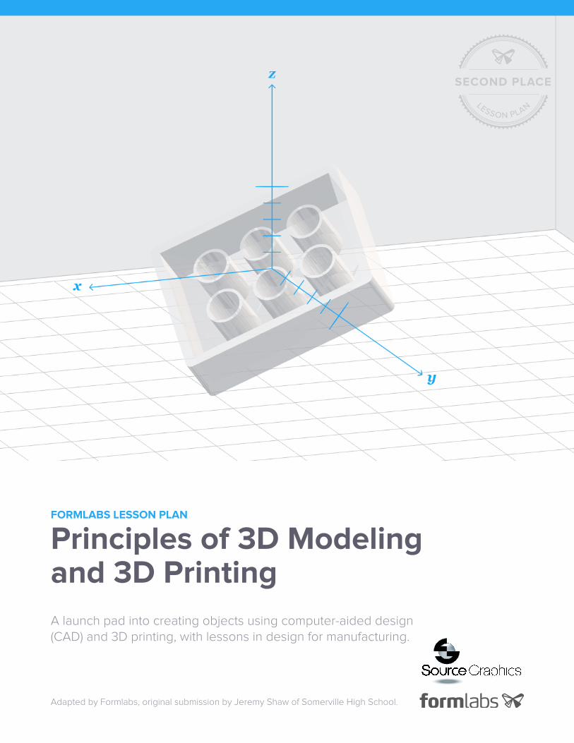
FORMLABS LESSON PLAN
Principles of 3D Modeling and 3D Printing
A launch pad into creating objects using computer-aided design (CAD) and 3D printing, with lessons in design for manufacturing.
Adapted by Formlabs, original submission by Jeremy Shaw of Somerville High School.

formlabs.com FORMLABS LESSON PLAN Principles of 3D Modeling and 3D Printing 2
Formlabs’ Innovate & Educate Challenge invited educators across the country to
develop and share lesson plans that encourage creative thinking and hands-on
learning through 3D printing. Thanks to those who submitted, we’re able to share
free resources with a wider learning community dedicated to inspiring students
with rich, immersive experiences.
Learn more about our growing library of lesson plans.
Missed the challenge but have an innovative lesson plan you’d like to share?
Find more information at formlabs.com/innovate-and-educate-challenge
Lesson plan tested and submitted by:
EDUCATOR
Jeremy ShawORGANIZATION
Somerville High School
LOCATION
Somerville, Massachusetts, USACONTACT
SUMMARY Principles of 3D Modeling and 3D Printing creates ties between the familiar Cartesian
coordinate system and modeling objects in three-dimensions with computer-based
software. The activities will challenge how students think about everyday objects
by distilling them first into planar projections. Students will experience a complete
design cycle, from brainstorming and taking measurements, to modeling, 3D
printing, and analyzing their products. This lesson will equip students with hands-
on foundations of CAD, 3D printing, and design for manufacturing.
OBJECTIVES • Learn about mathematical frameworks for modeling objects
in two dimensions and in three dimensions
• Learn how to model objects using CAD
• Learn about design for manufacturing
SUGGESTED AUDIENCE 8th – 12th grade students or beginner 3D designers
SUBJECT & INDUSTRY LINKS
Applicable Subjects Applicable Industries
mathematics
engineering
product design
manufacturing
research & education
engineering & product design
model making & entertainment
manufacturing

formlabs.com FORMLABS LESSON PLAN Principles of 3D Modeling and 3D Printing 3
LESSON OVERVIEW
5 min Do Now Sphere Students will make a prediction about how 3D modeling software is used to
create a sphere.
40 min Foundation Framing 2D and 3D Space Students are introduced to 2D vectors and 3D vectors
as a means of understanding the mathematical roots of 3D modeling software.
3 hr Exploration CAD Basics Students will be introduced to basic concepts of translating 2D
sketches into 3D models and will learn the fundamentals of a CAD software.
Modeling using CAD Students will create two models (a six-sided die and a
bowling pin) using dimensions they will find on their own. They will generate
assemblies if time allows.
Lego Challenge Students will be introduced to manufacturing using 3D printers and
will design, model, and print a custom part that connects to a standard Lego piece.
30 min Retrospective Precision The class will inspect their printed pieces and analyze dimensional
differences between their designs and their end products.
5 min Closing Looking Forward The class will discuss the manufacturing, cost, and other
implications of precision machining and the importance of designing with
machine-specific tolerances in mind.
* Download the .STL and .FORM files at: formlabs.com/esson-plan-principles-of-3d-modeling-and-3d-printing/
TOOLS & MATERIALS
TO SHARE
Form 2 & Resin PreForm Software .STL File * Whiteboard & Markers
PER STUDENT / GROUP
Computer Paper Pencil Ruler Onshape or other 3D Modeling (CAD) Software

formlabs.com FORMLABS LESSON PLAN Principles of 3D Modeling and 3D Printing 4
ACTIVITY ONE
5 min Do Now
1. Ask students to write down their prediction of how computer-aided design (CAD) software
is used to model a sphere.
ACTIVITY TWO
5 min Foundation
1. Introduce students to the relevance of 3D modeling in our day-to-day lives (see below).
2. Provide students with background information on vectors, planes, and the Cartesian coordinate system,
as they relate to 3D modeling with CAD software (see below).
3. Two-Dimensional Cartesian System: On the board, draw an X, Y coordinate plane with scale
marks. Draw a vector (V = 4,5) in Quadrant I and break the vector into its X (Vx = 4,0) and Y (Vy = 0,5)
components, where Vx + Vy = V.
4. Draw three additional vectors (arrows) on the board and ask students to decompose them into
their component vectors.
Tip: Each vector is the diagonal of a rectangle. Understanding how to mathematically determine the vertices
of the rectangle will greatly help with drawing vectors in a three-dimensional Cartesian system.
V = 4, 5
VERTEX X Y DESCRIPTION
1 0 0 origin
2 4 5 vector
3 4 0 x-component
4 0 5 y-component

formlabs.com FORMLABS LESSON PLAN Principles of 3D Modeling and 3D Printing 5
5. Three-Dimensional Cartesian System: On the board, draw an X, Y, Z coordinate plane with scale marks.
Walk through the steps of drawing a vector (V = 3, 2, 4) by way of a rectangular prism (see above Tip).
V = 3, 2, 4
VERTEX X Y Z DESCRIPTION
1 0 0 0 origin
2 3 2 4 vector
3 3 0 0 x-component
4 0 2 0 y-component
5 0 0 4 z-component
6 3 2 0 xy-vertex
7 0 2 4 yz-vertex
8 3 0 4 xz-vertex
6. Provide students with several (x,y,z) vector coordinates and instruct them to practice drawing the vectors
(V, Vx, Vy, and Vz) using the Cartesian coordinate system as demonstrated. e.g. (10, 10, 10), (5, 10, -5), (1, 3, 8).
formlabs.com FORMLABS LESSON PLAN Principles of 3D Modeling and 3D Printing 6
BACKGROUND 3D modeling is a visualization and analytical tool with many
purposes and benefits. Modeling enables ideas to be communicated,
structural feasibility of designs to be tested via simulations, and
parts and assemblies to be iteratively improved prior to fabrication.
For example, in the matter of days, a part can be modeled with
computer-aided design (CAD) software, its physical properties
can be analyzed under realistic forces, and engineers can update
the model as needed. Modeling saves companies valuable time,
money, and resources and is an integrated part of automotive,
defense, engineering, fashion, architecture, energy, game design,
entertainment, and medical industries, among others.
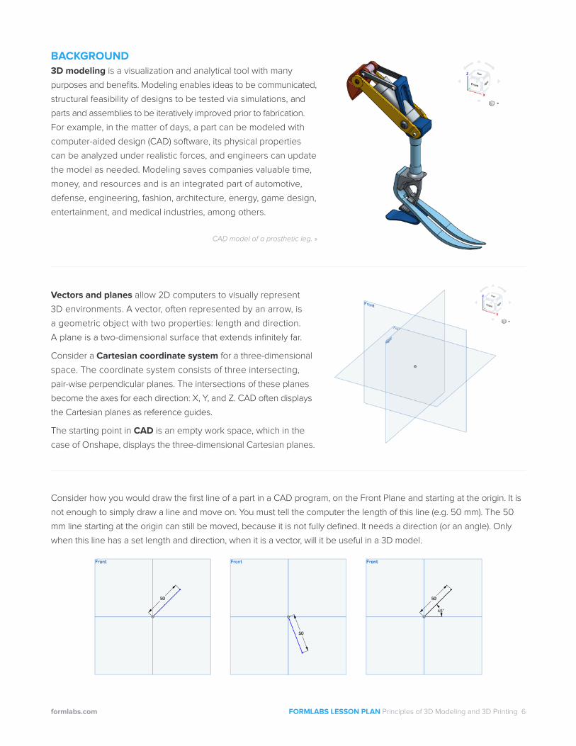
Vectors and planes allow 2D computers to visually represent
3D environments. A vector, often represented by an arrow, is
a geometric object with two properties: length and direction.
A plane is a two-dimensional surface that extends infinitely far.
Consider a Cartesian coordinate system for a three-dimensional
space. The coordinate system consists of three intersecting,
pair-wise perpendicular planes. The intersections of these planes
become the axes for each direction: X, Y, and Z. CAD often displays
the Cartesian planes as reference guides.
The starting point in CAD is an empty work space, which in the
case of Onshape, displays the three-dimensional Cartesian planes.
CAD model of a prosthetic leg. »
Consider how you would draw the first line of a part in a CAD program, on the Front Plane and starting at the origin. It is
not enough to simply draw a line and move on. You must tell the computer the length of this line (e.g. 50 mm). The 50
mm line starting at the origin can still be moved, because it is not fully defined. It needs a direction (or an angle). Only
when this line has a set length and direction, when it is a vector, will it be useful in a 3D model.

formlabs.com FORMLABS LESSON PLAN Principles of 3D Modeling and 3D Printing 7
ACTIVITY THREE
3 hr Exploration
1. Explain the principles of geometric and solid modeling to students.
2. Demonstrating with a CAD program, teach students about the process of converting 2D sketches
into 3D objects (extrude, revolve).
Optional: Draw a simple shape on the board (e.g. circle) and ask students what could be done with the circle to
turn it into different 3D shapes. Similarly, make a list of common 3D shapes (e.g. sphere, disc, cone, cube, dome)
on the board and ask students how 2D shapes could be used to model each.
3. Show students several images of CAD parts that were extruded and several that were revolved,
and ask students to draw the foundational sketch for each.
4. Discuss additional tools commonly available in CAD programs (e.g. sweep, loft, fillet, and chamfer, etc.),
as well as the power of rendering.
5. Introduce students to the command structure of the CAD program.
6.Challenge students to create a model of a six-sided die
(using either dots or numbers).
7. Challenge students to create a model of a bowling pin (candlepin or ten-pin) with the red stripes!
Optional: Ask students to also model a bowling ball and bowling lane, and to assemble bowling pins
and a bowling ball in a lane.

formlabs.com FORMLABS LESSON PLAN Principles of 3D Modeling and 3D Printing 8
BACKGROUND 3D modeling is founded on principles of both geometric and solid modeling. Geometric modeling involves
representing objects by equations, whereas solid modeling involves defining values (lengths, angles, and other
spatial relationships) within an object.
For example, a company has created a model for a bike. This geometric model is governed by a set of equations,
so that the frame can be scaled based on the height of different riders. Once rider heights are known, the geometric
model (equation-based) can be converted into a solid model (fully defined).
2D before 3D The 3D modeling design process begins with a 2D sketch. Consider a cylindrical part, a bushing,
within the bike frame model.
CAD model of a bike frame. CAD model of a bike frame, with a call-out to a cylindrical part called a ‘bushing’.
There are two basic ways this bushing can be modeled. It can
extruded from a circle or revolved from a rectangle. Extrusion
can be thought of as “pulling” or “stretching” a shape in a
specified direction; revolving is the process of rotating a sketch
around an axis.
Explore additional tools, such as sweep, loft, fillet, and chamfer,
and more.

formlabs.com FORMLABS LESSON PLAN Principles of 3D Modeling and 3D Printing 9
File Types There are several part files that are associated with CAD: part files, assembly files, drawing files, and files
that can be read by 3D printers (.STL files). A drawing is based on a part and depicts 2D views and dimensions of the
part. These drawings can be passed onto machinists, for instance, who use the drawing as a guide for what to make.
Parts can be combined into groups of parts, or assemblies.
Finishing Touches In addition to modeling the shape of objects, the material appearance of objects may also be
customized. The model of a glass tabletop can be edited to look like a glass tabletop. A rendering of the glass desk
in an office setting, with the appearance of natural light streaming through the windows, can be generated.
An example of a drawing generated
in a CAD program, Onshape.

formlabs.com FORMLABS LESSON PLAN Principles of 3D Modeling and 3D Printing 10
INSTRUCTIONS
1. 3D Printing Explain to students how stereolithography (SLA) printing works, alongside a live demo.
2. Challenge Provide each student with several standard Lego pieces. Introduce students to the next
activity: design, 3D model, and 3D print a custom Lego piece. This can be furniture for figurines, an
animal, or a specialized building part, for example.
3. Constraints Outline the design criteria:
• Custom piece must mate with a Lego piece
• Part must fit inside a 40 mm cube
• CAD file must be in metric units
• Minimum part thickness = 2 mm
• Add additional criteria as appropriate for your classroom.
4. Iteration One Allow students time to sketch several design ideas.
5. Design for Printing Explain additional nuances of designing for a 3D printer. Some examples
include: optimal part orientation, tolerance considerations, and the role of support material.
6. Feedback Provide students with design feedback, particularly if the design could be adapted
to be more 3D printable.
7. Iteration Two Ask students to modify their top-choice design based on feedback.
8. Lego Drawing Have students sketch an isometric view of the Lego piece that their custom
part will mate with. Ask students to leave one blank per dimension.
9. Dimensions Provide students with measuring tools (rulers, calipers, micrometers) for completing
their Lego drawings, with all dimensions.
10. CAD Assist students as they make a 3D model of their custom Lego parts.
11. PreForm Help students prepare their .STL files in PreForm, for optimal printing.
12. Print Parts Guide students through 3D printing and post-processing their parts.

ACTIVITY FOUR
30 min Retrospective
1. Measurements Have students measure all dimensions of their printed parts, using the appropriate
measuring tools, and create a labeled drawing of their part.
2. Analysis It is expected that not all designed dimensions will align with the actual measurements. Ask
students to complete a per-dimension analysis, comparing their design values to their actual values, and
to hypothesize reasons for discrepancies.
ACTIVITY FIVE
5 min Closing
1. Retrospective Ask students to consider the implications of manufacturing precise parts on the machine
(3D printer) design, the speed of the print, the cost of the part, and any other relevant factors?
Background
Due to a number of factors (printer, print method, machine cost, machine age) prototyped parts will not
exactly match their 3D models. Printer clarity can be discussed in terms of horizontal resolution (XY
resolution) and vertical resolution (layer thickness). The less movement the printer can make on the X
and Y axes, and the smaller the layer thickness, the smoother and more precise the printed surface
will be. Note that there are time and cost tradeoffs with higher precision. SLA 3D printers can produce
high-resolution objects. Their resolution is directly linked to the optical spot size of the laser, which is 140
microns for the Form 2.
A benefit to 3D printing is the ability to quickly iterate. Once design-to-actual part differences are
determined, the design can be modified to improve the part precision.
1530 North Harmony CircleAnaheim, CA 92807
800-791-9042www.sourcegraphics.com