Embed Size (px)
Citation preview
CHAPTER 19
Forming and Shaping Plastics
and Composite Materials
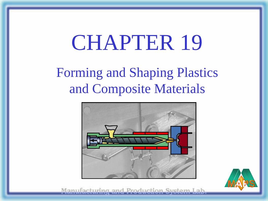
Examples of Injection Molding
Figure 19.9 Typical products made by injection molding, including examples of insert molding.
Source: (a) Courtesy of Plainfield Molding, Inc. (b) Courtesy of Rayco Mold and Mfg. LLC.
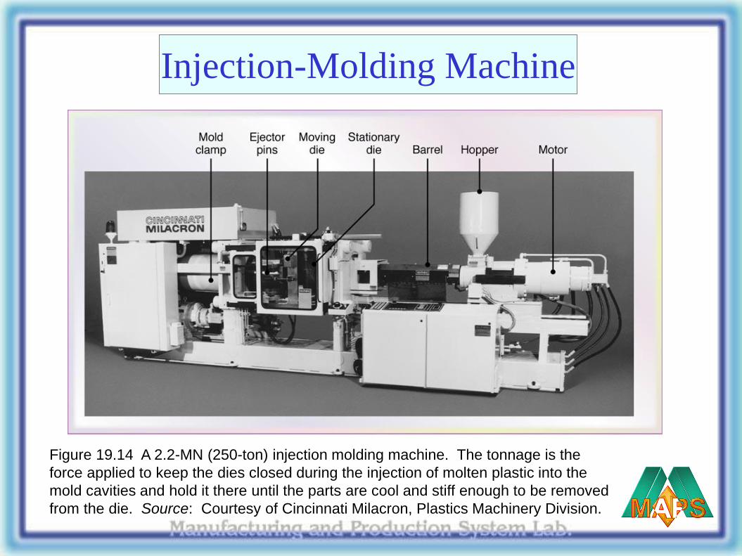
Injection-Molding Machine
Figure 19.14 A 2.2-MN (250-ton) injection molding machine. The tonnage is the
force applied to keep the dies closed during the injection of molten plastic into the
mold cavities and hold it there until the parts are cool and stiff enough to be removed
from the die. Source: Courtesy of Cincinnati Milacron, Plastics Machinery Division.
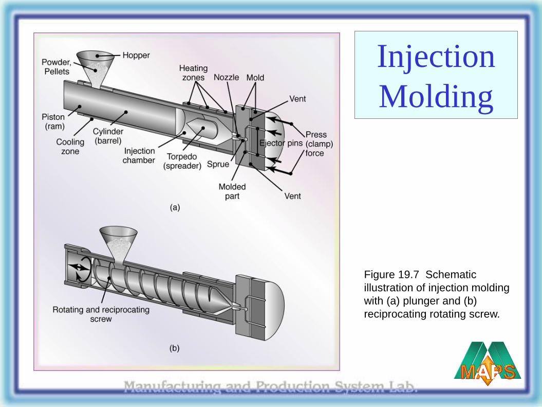
Injection
Molding
Figure 19.7 Schematic
illustration of injection molding
with (a) plunger and (b)
reciprocating rotating screw.
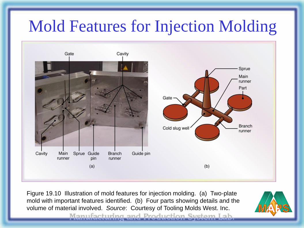
Mold Features for Injection Molding
Figure 19.10 Illustration of mold features for injection molding. (a) Two-plate
mold with important features identified. (b) Four parts showing details and the
volume of material involved. Source: Courtesy of Tooling Molds West. Inc.
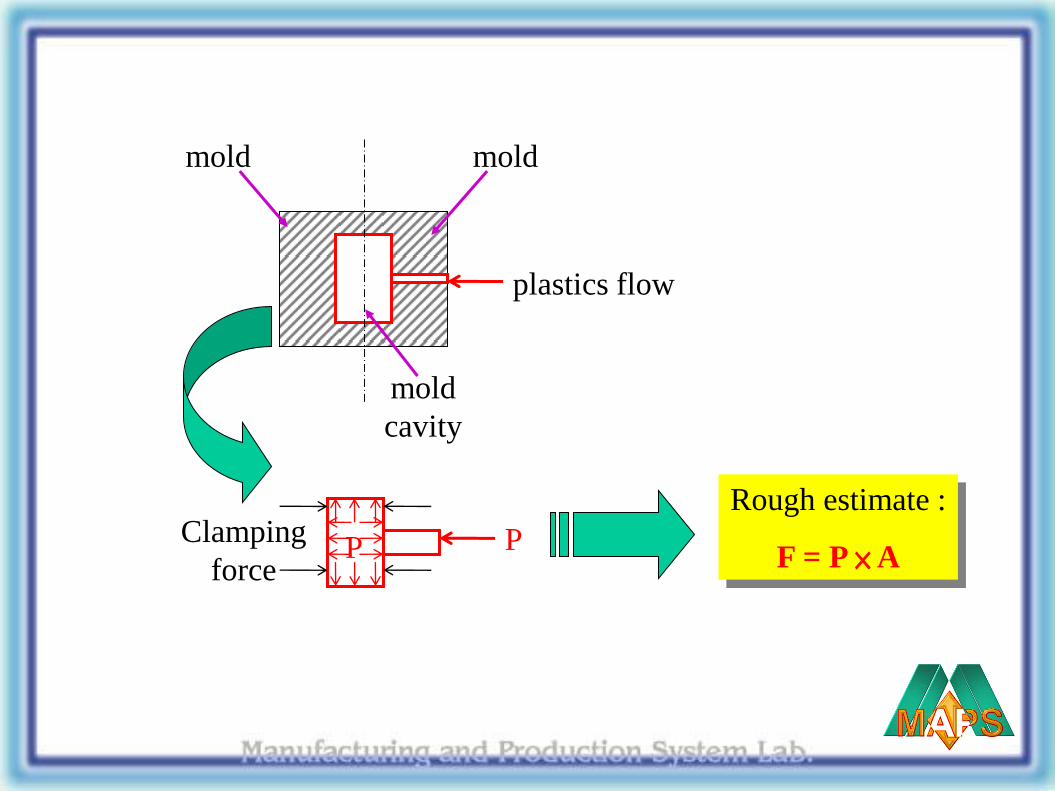
mold mold
mold
cavity
plastics flow
P P Clamping
force
Rough estimate :
F = P × A
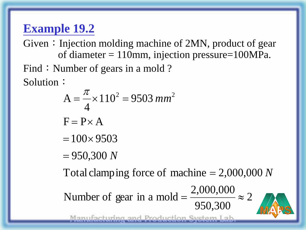
Example 19.2
Given:Injection molding machine of 2MN, product of gear of diameter = 110mm, injection pressure=100MPa.
Find:Number of gears in a mold ?
Solution:
2950,300
2,000,000moldaingearofNumber
2,000,000machineofforceclampingTotal
300,950
9503100
APF
95031104
A 22
N
N
mm
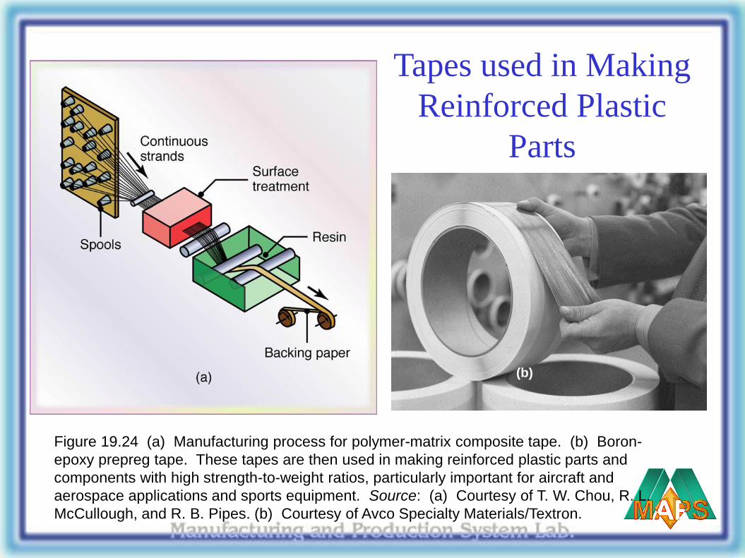
Tapes used in Making
Reinforced Plastic
Parts
Figure 19.24 (a) Manufacturing process for polymer-matrix composite tape. (b) Boron-
epoxy prepreg tape. These tapes are then used in making reinforced plastic parts and
components with high strength-to-weight ratios, particularly important for aircraft and
aerospace applications and sports equipment. Source: (a) Courtesy of T. W. Chou, R. L.
McCullough, and R. B. Pipes. (b) Courtesy of Avco Specialty Materials/Textron.
(b)
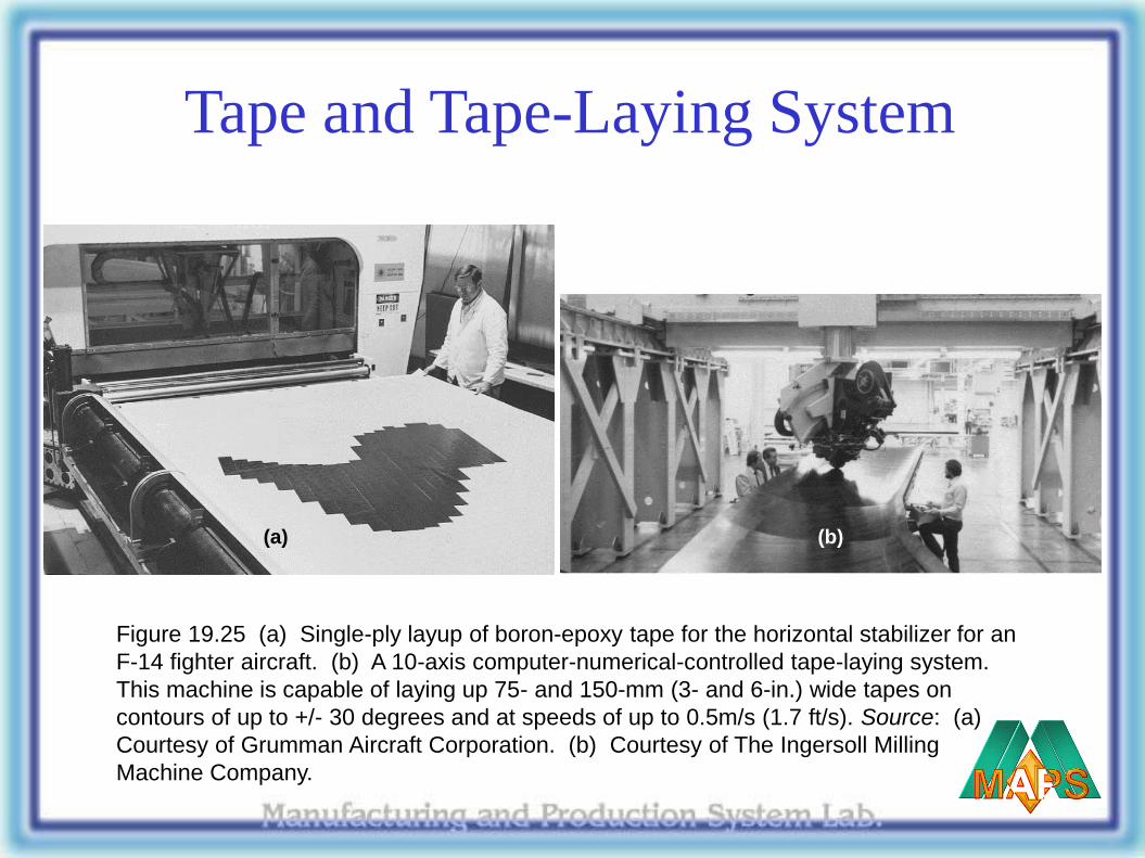
Tape and Tape-Laying System
(b) (a)
Figure 19.25 (a) Single-ply layup of boron-epoxy tape for the horizontal stabilizer for an
F-14 fighter aircraft. (b) A 10-axis computer-numerical-controlled tape-laying system.
This machine is capable of laying up 75- and 150-mm (3- and 6-in.) wide tapes on
contours of up to +/- 30 degrees and at speeds of up to 0.5m/s (1.7 ft/s). Source: (a)
Courtesy of Grumman Aircraft Corporation. (b) Courtesy of The Ingersoll Milling
Machine Company.
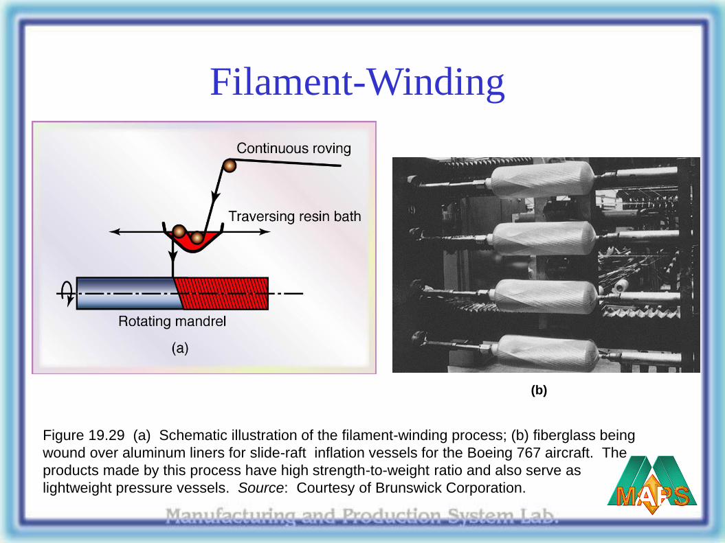
Filament-Winding
(b)
Figure 19.29 (a) Schematic illustration of the filament-winding process; (b) fiberglass being
wound over aluminum liners for slide-raft inflation vessels for the Boeing 767 aircraft. The
products made by this process have high strength-to-weight ratio and also serve as
lightweight pressure vessels. Source: Courtesy of Brunswick Corporation.
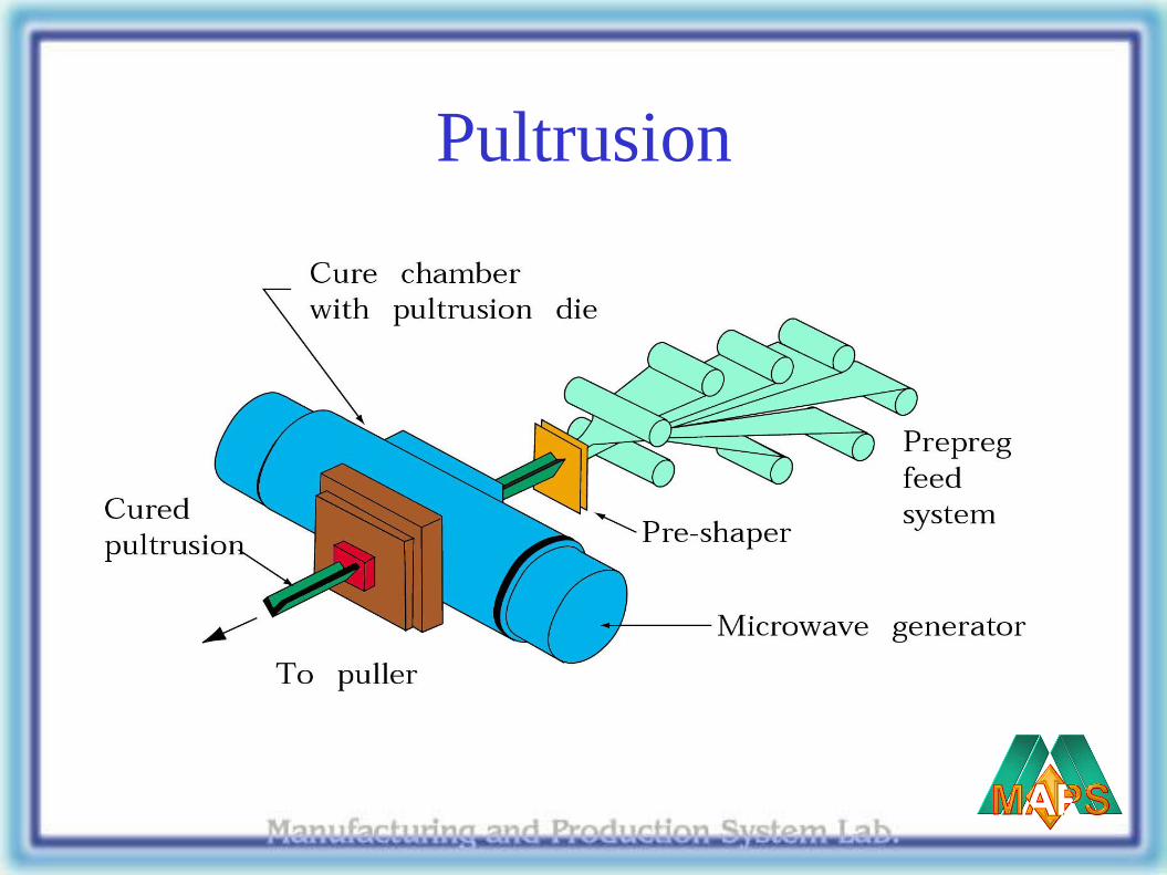
Pultrusion
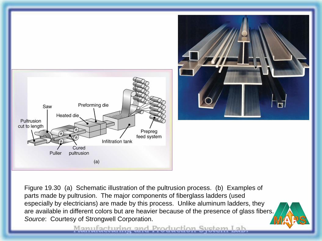
Figure 19.30 (a) Schematic illustration of the pultrusion process. (b) Examples of
parts made by pultrusion. The major components of fiberglass ladders (used
especially by electricians) are made by this process. Unlike aluminum ladders, they
are available in different colors but are heavier because of the presence of glass fibers.
Source: Courtesy of Strongwell Corporation.
(b)

Ch 19
略讀:19.3(without 19.3.1).