Embed Size (px)
Citation preview
Format for Manuscript Submission: Therapeutic Advances
Name of Journal: World Journal of Anesthesiology
Manuscript Type: Therapeutics Advances
Review of essential understanding of ultrasound physics and equipment operation
Shanthanna H. Essentials of ultrasound physics and operation
Harsha Shanthanna
Harsha Shanthanna, Department of Anesthesiology, St Joseph’s Hospital, Health
Sciences Centre 2U1, McMaster University, Hamilton L8N 3Z5, Canada
ORCID number: Harsha Shanthanna ( ).
Author contributions: This manuscript was written completely by the stated author.
Supported by
Conflict-of-interest statement:
Correspondence to: Harsha Shanthanna, MBBS, MD, DNB, FIPP, EDRA, Assistant
Professor, Department of Anesthesiology, St Joseph’s Hospital, Health Sciences Centre
2U1, McMaster University, 1200 Main Street West, Hamilton, L8N 3Z5, Canada.
Telephone: +1-905-5221155-33853

Fax: +1-905-5221155
Abstract
Ultrasound (US) is being extensively used an imaging tool in regional anesthesia (RA)
and pain practice. Although it was first used in a regional block in 1978, it was only in
1994 that the first direct use of US in RA was reported. Like any other medical tool, its
utility is only realized when the performing physician is able to understand the
principles behind its application. Efficient use of US also requires an understanding of
physical variables which can be suitable modified to produce a clear image of the
structure of importance. This brief narrative review summarises the advantages of US in
RA and pain practice over the conventionally used localising or imaging tools. The
second section deals with the physics behind ultrasound. It highlights the necessary
physical concepts such as wavelength, frequency, generation of US waves. It also
informs the reader about the possible ultrasound and tissue interactions, use of US
transducers and their differences. The third section deals with understanding the
control variables in a typical US machine and how they could be modified to improve
the image quality. The final section highlights the various artifacts that could be
associated.
Key words: Ultrasound physics; Ultrasound in regional anesthesia; Essential concepts
of ultrasound; Ultrasound basics; Artifacts
Core tip:
Shanthanna H. Review of essential understanding of ultrasound physics and equipment
operation.
INTRODUCTION
Ultrasound (US) is being increasingly employed in the field of anesthesiology and pain
medicine. Medical use of ultrasound, for diagnostic brain imaging was first done by Dr
Karl Theo Dussik[1]. The published report of Doppler technology for regional block
came in 1978[2]. Subsequently it was not popularly used in the field of anesthesia until
the last couple of centuries. The first direct use of ultrasound for regional block was
performed in 1994[3]. The number of physicians who use it in their daily practice has
increased significantly. Although tremendously useful, it is still a machine and it is up
to the physician using it to make the most of it. As Dr. Marhofer has said, informed
scepticism should accompany an increasing enthusiasm[4]. The appropriate use of US
technology in regional anesthesia (RA) requires a thorough knowledge of anatomy, an
essential understanding of its working, and adequate training in the use of needling
techniques. Accordingly essential categories of training in US guided interventional
procedures are supposed to involve: (1) understanding device operations, (2) image
optimization, (3) image interpretation, and (4) visualisation of needle insertion and
injection[5]. This review summarises the physical principles involved in US operation
and also an understanding of the equipment involved and its appropriate use.
SECTION 1
Advantages of Ultrasound as an imaging modality
Ultrasound has several advantages over the conventional imaging or nerve localisation
modalities. In the field of RA ultrasound clearly has several potential advantages (Table
1) over the nerve stimulation methods. Although improvement in patient safety during
RA procedures could be debatable, there continues to be a surge of publications
reporting better technical performance, lesser complications and increased safety with
the use of US[6].
In the field of interventional pain medicine (IPM), fluoroscopy to a major extent and
CT scan to some extent have been used as imaging modalities. There are important
challenges for the use of US guidance in IPM. Most involve precision placement of
needles around neuraxis. However ultrasound is still very useful for injection of
superficial structures such as stellate ganglion, inguinal nerves, intercostals nerves;
deep intramuscular injections such as piriformis, trigger points, BOTOX injections.
Narouze et al[7] detail the pain interventions that can be done with the use of US. They
also list the level of difficulty associated.
SECTION 2
Understanding the physics behind the use of US
Ultrasound waves are a form of sound waves. US wave frequencies exceed the upper
limit of audible human hearing. Medical US frequencies are in the range of 1-20 MHz.
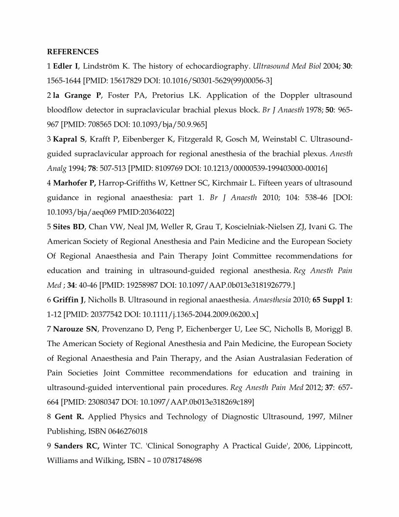
Each US wave is characterised by a specific frequency and wavelength, which are
inversely related (Figure 1). The higher the frequency, lower the wavelength. Frequency
is the number of cycles per second and is measured in Hertz.
Wavelength is the distance between two consecutive, similar positions in the pressure
wave. It is determined by the frequency of the wave, and the speed of propagation in
the medium it is passing through. Actually the speed of sound is different based on the
tissues through which it propagates: air-330 m/s, water-1525 m/s, bone 3000 m/s, fat-
1450 m/s, muscle-1600 m/s and blood-1560 m/s. However it is averaged as
approximately 1540 meters/second for the entire body and is referred to as propagation
velocity or acoustic velocity[8,9].
The US waves are produced by piezoelectric effect, which was discovered by Curie
brothers in 1880[10]. It involves the generation of an electrical charge, by a piezoelectric
material, when subjected to mechanical stress and the reverse piezoelectric effect
involves such an electrical charge being converted to mechanical vibration. In the
available US machines the transducer holding the piezoelectric material acts both as a
generator and receiver of such signals. US used in medical imaging is referred to as B-
mode (2D), meaning brightness mode display. This means the brightness of the pixel on
the image is a representation of the strength of reflection.
A source of alternating current makes the piezoelectric crystals to vibrate at high
frequency producing US waves. This is then transmitted to the patient through a
conductive gel. These sound waves go through structures underneath the transducer
and information is relayed back as reflected sound waves. A transducer acts as a
generator of US waves for only 1% of the time and acts as a microphone to listen to the
incoming waves for the rest 99% of the time. Frame rate refers to number of such pulses
of US waves[11]. Higher frequency produces more waves of compression and rarefaction
in a given time and increases the resolution (ability to discriminate between 2 separate
structures along the axial plane).
Us equipment
Medical US utilises a transducer attached to a display monitor which also holds the
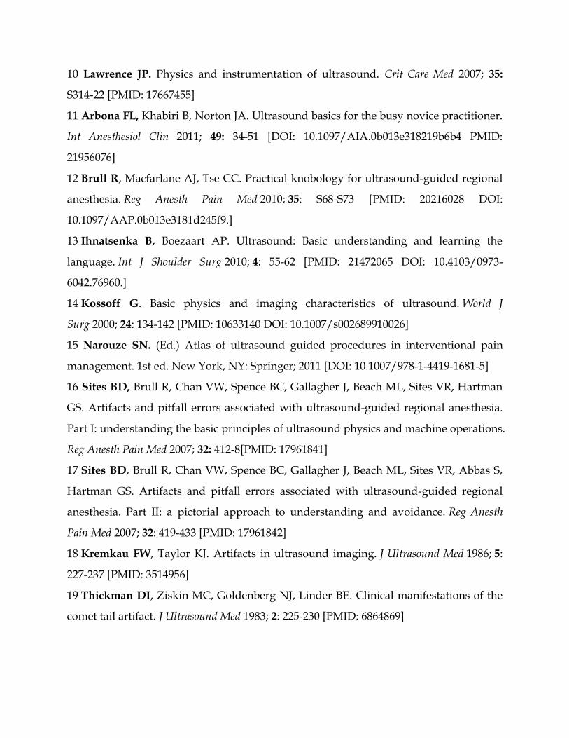
operating console. A transducer also known as probe contains damping material,
piezoelectric crystals, a matching layer and a protective layer (Figure 2). Each crystal is
isolated and hence transmits its own ultrasound wave. The damping layer, present just
behind the crystals acts to reduce their resonance so that they are sensitive to the
returning signal. The matching layer in front acts to reduce the impedance mismatch
and is covered by a protective layer[10].
There are several types of transducers and it is necessary to choose the right one for
the procedure. Based on the frequency range, commonly 2 types of transducers are used
for RA procedures[10] (Figure 3). Some others give 3 varieties, based on the range: high-
(8-12 MHz), medium- (6-10 MHz), and low- (2-5 MHz)[12]. The smaller one with a
straight contact surface is called a linear array transducer due to the linear arrangement
of crystals. It also produces high frequency waves in the range of 8-12 MHz. Its
penetration, and hence resolution is usually good for structures within 3-4 cm. The
larger one with a curved contact surface is called a curved array or curvilinear
transducer because of the curved arrangement of crystals[8,9]. It creates a wedge shaped
US beam and produces a much broader view with the image of deeper structures being
wider than the footprint of the probe. It is used to visualise deeper structures, beyond 4
cm. It is important to know that the width of the image is equal to the probe footprint
size only at the uppermost part of the image and hence any determination of depth is
tricky[13].
Us tissue interaction
Once generated the wave passes through various tissue structures and thereby interacts
with them. This interaction results in various possibilities as shown in Figure 4.
Ultrasound waves are primarily influenced by physical changes involving reflection,
refraction and attenuation. The reflected wave, which gives rise to the resulting signal,
is dependent upon the underlying structures the waves encounter. This property is
called acoustic impedance[14]. It is unique to each tissue type and is defined as the
density of the medium times the velocity of US wave transmitted through it. Less dense
organs such as lungs have the lowest impedance in contrast to bones which would have
high impedance. The greater the differences in acoustic impedance between 2 adjacent
tissues, more waves are reflected back. So it is not individual acoustic impedances but
the relative difference of it among adjacent tissues that control the amount of energy
reflected back[15].
Specular reflection involves a large smooth surface, such as a needle. Depending
upon the incident angle, a large amount of US waves are reflected back to the
transducer. Scattered reflection involves an irregular surface giving rise to scattering
and hence loss of signal. However due to the wide range of angles, regardless of the
incident angle, some US energy is always reflected back. Most biological tissues fall into
this category and give rise to the speckled appearance observed of most soft tissues[16].
Refraction involves changes in the direction of US waves due to an interface of tissues
with different speeds of sound transmission. This is similar to seeing a bent spoon when
observed in a glass of water. This gives rise to loss of energy when not captured from
the transducer[16]. Even when captured, acts as a source of several artifacts (duplication
error) commonly encountered[15]. Attenuation refers to the loss of energy as the sound
waves travel through increasing depth. It is related to the depth of beam penetration,
type of tissue being imaged and the frequency of the wave. Due to friction, a vast
amount of energy is lost as heat. More dense structures have higher attenuation
coefficients as the oscillatory tissue motion produced by the sound wave creates more
friction and heat[15]. Higher frequency signals are attenuated more than the lower
frequency signals. Hence a high frequency probe cannot be of much help in visualising
deeper structures such as sciatic nerve. Posterior acoustic enhancement, a commonly
observed artefact, is largely due to an intrinsic compensating mechanism provided to
counter the attenuation and loss of signal when imaging highly hyperechoic structures
such as blood vessels[15]. Transmission refers to loss of signal due to unopposed
transmission away from the probe[16].
SECTION 3
Understanding the controls and improving the image quality (Figure 5)
A good use of US guidance can only be made when one understands how to operate the
equipment and also how to modify the variables to get the best possible image. The
following section gives an understanding of these elements.
Resolution: it describes the ability to separately identify to individual structures[8,12].
Axial resolution refers to the possible differentiation between the 2 in the plane of US
beam. Higher frequencies and superficial structures give better axial resolution[10].
Temporal resolution refers to the rate at which consecutive images are visualised. It
depends on the frame rate or pulses. A transducer emits the next pulse only after it has
received the previous pulse. Increasing the depth of US beam affects the temporal
resolution. Similarly using Doppler has the same effect as it requires more time to
process the incoming signals and hence lower temporal resolution. Lateral resolution
refers to separation of structures lying side by side. Inappropriate use of focus zone-as
explained below can decrease the lateral resolution. Contrast resolution is referred to
the optimal visualisation achieved in terms of hyper and hypo-echogeneic structures
displayed on the screen. To enhance visualisation and to improve resolution there are 3
important settings which can be altered.
GAIN: This simply refers to the strength of the signal. The brightness of the image is
proportional to the strength of the signal received by the transducer. A highly reflective
structure sends back proportionately more sound signals causing whiter shadow-
hyperechogenic, where as less denser and les reflective structures send back less
signals to the transducer causing blacker shadow-hypoechogenic. Increasing the gain
increases the signal strength and brightness in general. This may not be optimal as even
the background structures (noise) are also increased[12]. The optimal gain necessary for
visualisation might be different from what is set as auto-gain and might need
individual adjustments. Such well adjusted image is referred to as contrast resolution.
Increasing the gain can also affect lateral resolution.
FOCUS: The sound waves converge to a point called focal zone and then diverge[10].
The divergence of these waves beyond the focal zone can allow for missed information
in a horizontal plane. To minimise this loss, it is important to set the focal zone at the
same level as the target of interest. It is achieved usually by a dial setting and is
observed on the monitor as a small arrow on either side of the screen (Figure 6).
Time gain compensation: As the name suggests there is an increase in gain (signal
strength) which is restricted to a set field of depth. Attenuation increases with
increasing depth. To compensate for this time gain compensation (TGC) allows for
stepwise increase in gain which can be adjusted for a particular depth. It is suggested
that TGA adjustments are made less frequently than gain adjustments, which is not
usually optimal[16].
Frequency: Waves of higher frequency are more attenuated. One should choose a
higher frequency probe for superficial structures, and low frequency probe for deeper
structures.
Color doppler: This function helps to detect structures with movement, like blood flow.
It is based on the doppler principle. Structures moving away from the probe appear
blue and those towards the probe appear red. One important thing to remember is that
the angle of incidence should be as less as possible. With an angle of incidence of 90O,
no flow is detected and might provide a false negative implication. To help visualise
even smaller vessels and also to be independent of the incident angle, newer machines
have power Doppler[9,13]. This function provides only a single color pattern.
SECTION 4
Artifacts associated with US imaging
The image produced on the monitor is a 2 dimensional image obtained from converting
mechanical energy into electrical signals. The actual conversion of signals into images
involves several assumptions on the part of equipment’s software[8,9]. These give rise to
artifacts: could be a distortion in the image brightness, duplication, absence of echoes,
etc.
It is difficult to avoid them altogether and hence must be able to distinguish them[17].
Commonly understood artifacts are described below.
Acoustic Shadowing: This happens when a superficial structure has greater attenuation
coefficient than the structures deep to it. Due to this the underlying structure appears
less echogenic than normal. This is typically seen under a bone as a black shadow[8,18].
Posterior acoustic enhancement: This is almost the opposite of shadowing. Due to the
presence of a less attenuating structure superficially, the region behind that structure
produces stronger echoes than the surrounding structures. This is typically seen
underneath or posterior to a blood vessel and can be mistaken as a nerve due to its
hyperechoic quality[8,17].
Reverbation: It is the multiple representation of the same structure at different depths
of display. It is usually caused by a specular reflector such as a needle. It reflects a
strong signal back to the tranducer, some of which is again reflected back to cause a
repeat of the shadow at a different depth, because of the time delay involved. The
lumen and the walls of a hollow needle can also give rise to reverberation artifacts due
to differences in the time of reflected wave and appear as multiple but similar shadows.
They also give rise to comet tail shadows[19].
Mirror image: It is a type of reverberation artifact,ccommonly produced due to a
significan mismatch in the acoustic impedance between 2 adjacent structures such as
air-bone, soft tissue-lung etc. Interestingly this artifact appears in all modes including
doppler.
Refraction: This is also called as bayonet effect[20]. This appears as a subtle bend in the
length of the needle due to refraction.
Dealing with artifacts[8,17]: (1) Have a high degree of suspicion; (2) Confirm in 2 views,
longitudinal and cross-sectional; (3) Change the position of transducer-move proximal
or distal; (4) Reduce gain; and (5) Move the patient.
CONCLUSION
Appropriate and effective use of ultrasound requires a thorough knowledge of its
operating principles. This helps one to utilise the controls to get an optimal image
which is clear, with more signal transmission than background noise.
Key points include: selection of the right transducer, using focus adjustment, using
TGC to allow for compensation at the required depth, using appropriate doppler
imaging. All of these help to minimise the artifacts.
REFERENCES
1 Edler I, Lindström K. The history of echocardiography. Ultrasound Med Biol 2004; 30:
1565-1644 [PMID: 15617829 DOI: 10.1016/S0301-5629(99)00056-3]
2 la Grange P, Foster PA, Pretorius LK. Application of the Doppler ultrasound
bloodflow detector in supraclavicular brachial plexus block. Br J Anaesth 1978; 50: 965-
967 [PMID: 708565 DOI: 10.1093/bja/50.9.965]
3 Kapral S, Krafft P, Eibenberger K, Fitzgerald R, Gosch M, Weinstabl C. Ultrasound-
guided supraclavicular approach for regional anesthesia of the brachial plexus. Anesth
Analg 1994; 78: 507-513 [PMID: 8109769 DOI: 10.1213/00000539-199403000-00016]
4 Marhofer P, Harrop-Griffiths W, Kettner SC, Kirchmair L. Fifteen years of ultrasound
guidance in regional anaesthesia: part 1. Br J Anaesth 2010; 104: 538-46 [DOI:
10.1093/bja/aeq069 PMID:20364022]
5 Sites BD, Chan VW, Neal JM, Weller R, Grau T, Koscielniak-Nielsen ZJ, Ivani G. The
American Society of Regional Anesthesia and Pain Medicine and the European Society
Of Regional Anaesthesia and Pain Therapy Joint Committee recommendations for
education and training in ultrasound-guided regional anesthesia. Reg Anesth Pain
Med ; 34: 40-46 [PMID: 19258987 DOI: 10.1097/AAP.0b013e3181926779.]
6 Griffin J, Nicholls B. Ultrasound in regional anaesthesia. Anaesthesia 2010; 65 Suppl 1:
1-12 [PMID: 20377542 DOI: 10.1111/j.1365-2044.2009.06200.x]
7 Narouze SN, Provenzano D, Peng P, Eichenberger U, Lee SC, Nicholls B, Moriggl B.
The American Society of Regional Anesthesia and Pain Medicine, the European Society
of Regional Anaesthesia and Pain Therapy, and the Asian Australasian Federation of
Pain Societies Joint Committee recommendations for education and training in
ultrasound-guided interventional pain procedures. Reg Anesth Pain Med 2012; 37: 657-
664 [PMID: 23080347 DOI: 10.1097/AAP.0b013e318269c189]
8 Gent R. Applied Physics and Technology of Diagnostic Ultrasound, 1997, Milner
Publishing, ISBN 0646276018
9 Sanders RC, Winter TC. 'Clinical Sonography A Practical Guide', 2006, Lippincott,
Williams and Wilking, ISBN – 10 0781748698
10 Lawrence JP. Physics and instrumentation of ultrasound. Crit Care Med 2007; 35:
S314-22 [PMID: 17667455]
11 Arbona FL, Khabiri B, Norton JA. Ultrasound basics for the busy novice practitioner.
Int Anesthesiol Clin 2011; 49: 34-51 [DOI: 10.1097/AIA.0b013e318219b6b4 PMID:
21956076]
12 Brull R, Macfarlane AJ, Tse CC. Practical knobology for ultrasound-guided regional
anesthesia. Reg Anesth Pain Med 2010; 35: S68-S73 [PMID: 20216028 DOI:
10.1097/AAP.0b013e3181d245f9.]
13 Ihnatsenka B, Boezaart AP. Ultrasound: Basic understanding and learning the
language. Int J Shoulder Surg 2010; 4: 55-62 [PMID: 21472065 DOI: 10.4103/0973-
6042.76960.]
14 Kossoff G. Basic physics and imaging characteristics of ultrasound. World J
Surg 2000; 24: 134-142 [PMID: 10633140 DOI: 10.1007/s002689910026]
15 Narouze SN. (Ed.) Atlas of ultrasound guided procedures in interventional pain
management. 1st ed. New York, NY: Springer; 2011 [DOI: 10.1007/978-1-4419-1681-5]
16 Sites BD, Brull R, Chan VW, Spence BC, Gallagher J, Beach ML, Sites VR, Hartman
GS. Artifacts and pitfall errors associated with ultrasound-guided regional anesthesia.
Part I: understanding the basic principles of ultrasound physics and machine operations.
Reg Anesth Pain Med 2007; 32: 412-8[PMID: 17961841]
17 Sites BD, Brull R, Chan VW, Spence BC, Gallagher J, Beach ML, Sites VR, Abbas S,
Hartman GS. Artifacts and pitfall errors associated with ultrasound-guided regional
anesthesia. Part II: a pictorial approach to understanding and avoidance. Reg Anesth
Pain Med 2007; 32: 419-433 [PMID: 17961842]
18 Kremkau FW, Taylor KJ. Artifacts in ultrasound imaging. J Ultrasound Med 1986; 5:
227-237 [PMID: 3514956]
19 Thickman DI, Ziskin MC, Goldenberg NJ, Linder BE. Clinical manifestations of the
comet tail artifact. J Ultrasound Med 1983; 2: 225-230 [PMID: 6864869]

20 Gray AT, Schafhalter-Zoppoth I. "Bayonet artifact" during ultrasound-guided
transarterial axillary block. Anesthesiology 2005; 102: 1291-1292 [PMID: 15915056 DOI:
10.1097/00000542-200506000-00043]
Figure 1 Ultrasound waveform.
Figure 2 Typical transducer.
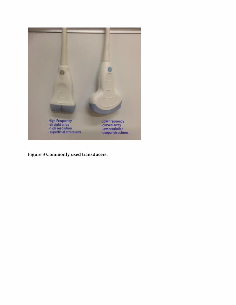
Figure 3 Commonly used transducers.
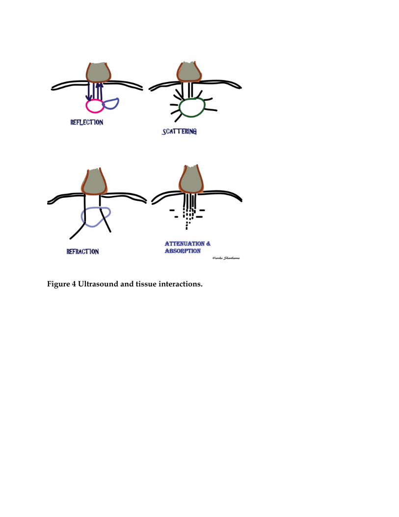
Figure 4 Ultrasound and tissue interactions.
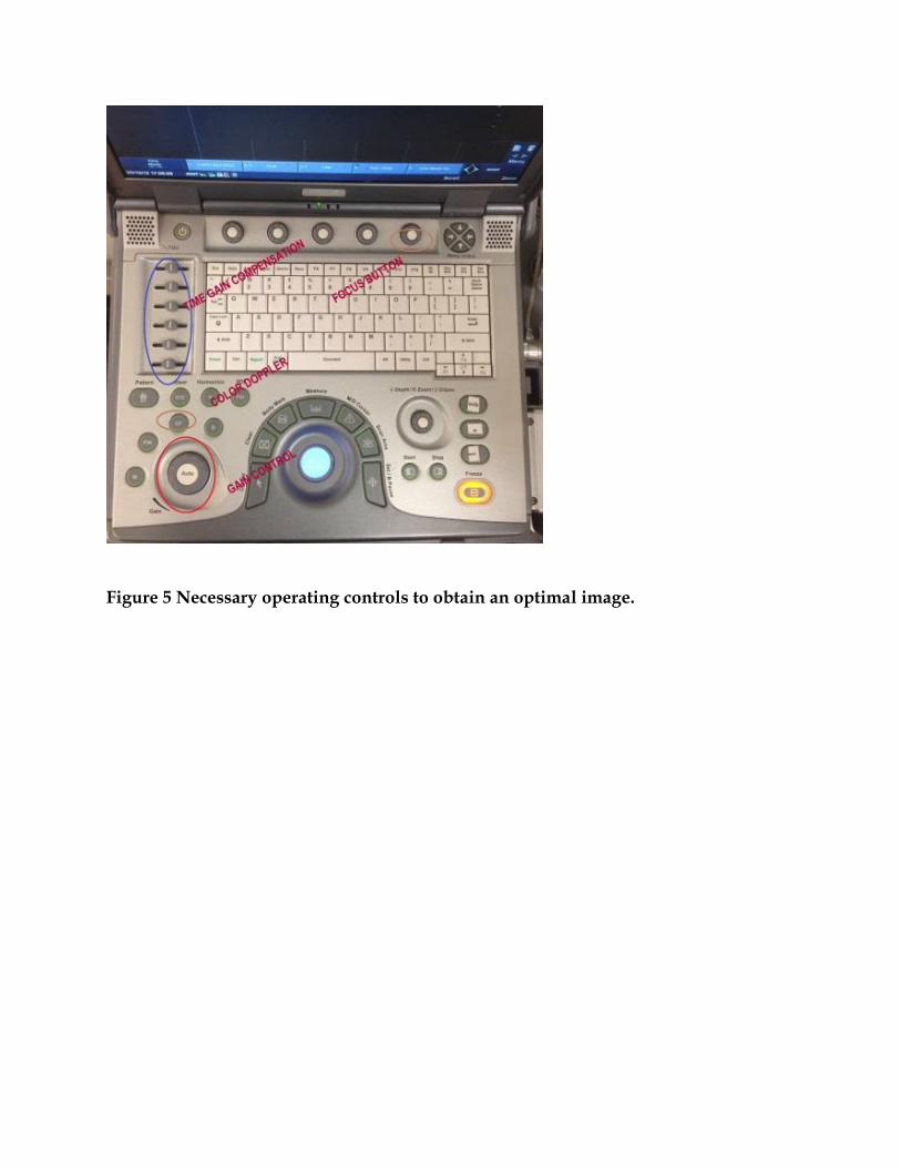
Figure 5 Necessary operating controls to obtain an optimal image.
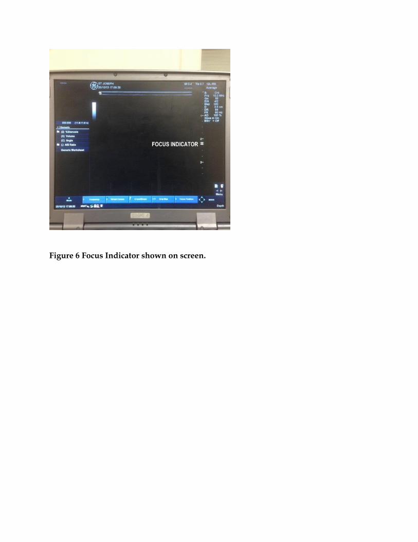
Figure 6 Focus Indicator shown on screen.
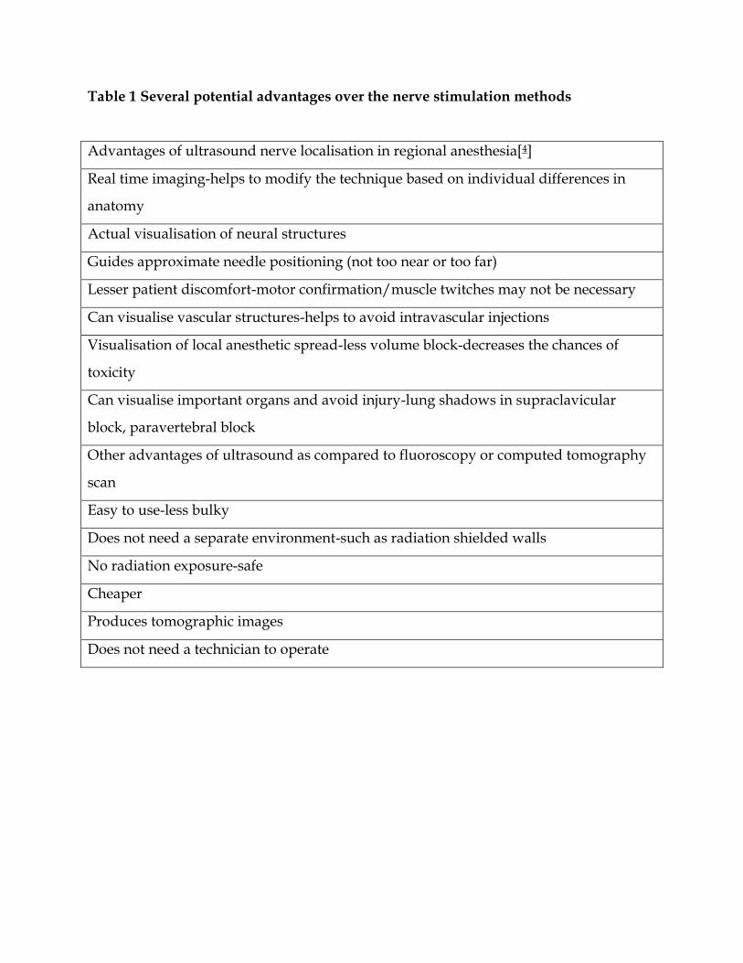
Table 1 Several potential advantages over the nerve stimulation methods
Advantages of ultrasound nerve localisation in regional anesthesia[4]
Real time imaging-helps to modify the technique based on individual differences in
anatomy
Actual visualisation of neural structures
Guides approximate needle positioning (not too near or too far)
Lesser patient discomfort-motor confirmation/muscle twitches may not be necessary
Can visualise vascular structures-helps to avoid intravascular injections
Visualisation of local anesthetic spread-less volume block-decreases the chances of
toxicity
Can visualise important organs and avoid injury-lung shadows in supraclavicular
block, paravertebral block
Other advantages of ultrasound as compared to fluoroscopy or computed tomography
scan
Easy to use-less bulky
Does not need a separate environment-such as radiation shielded walls
No radiation exposure-safe
Cheaper
Produces tomographic images
Does not need a technician to operate