Embed Size (px)
Citation preview
Comments?Send comments on the documentation by goingto http://solvnet.synopsys.com, then clicking“Enter a Call to the Support Center.”
Formality®
User GuideVersion Z-2007.06, June 2007

ii
Copyright Notice and Proprietary InformationCopyright © 2007 Synopsys, Inc. All rights reserved. This software and documentation contain confidential and proprietaryinformation that is the property of Synopsys, Inc. The software and documentation are furnished under a license agreement andmay be used or copied only in accordance with the terms of the license agreement. No part of the software and documentation maybe reproduced, transmitted, or translated, in any form or by any means, electronic, mechanical, manual, optical, or otherwise,without prior written permission of Synopsys, Inc., or as expressly provided by the license agreement.
Right to Copy DocumentationThe license agreement with Synopsys permits licensee to make copies of the documentation for its internal use only.Each copy shall include all copyrights, trademarks, service marks, and proprietary rights notices, if any. Licensee mustassign sequential numbers to all copies. These copies shall contain the following legend on the cover page:
“This document is duplicated with the permission of Synopsys, Inc., for the exclusive use of__________________________________________ and its employees. This is copy number __________.”
Destination Control StatementAll technical data contained in this publication is subject to the export control laws of the United States of America.Disclosure to nationals of other countries contrary to United States law is prohibited. It is the reader’s responsibility todetermine the applicable regulations and to comply with them.
DisclaimerSYNOPSYS, INC., AND ITS LICENSORS MAKE NO WARRANTY OF ANY KIND, EXPRESS OR IMPLIED, WITHREGARD TO THIS MATERIAL, INCLUDING, BUT NOT LIMITED TO, THE IMPLIED WARRANTIES OFMERCHANTABILITY AND FITNESS FOR A PARTICULAR PURPOSE.
Registered Trademarks (®)Synopsys, AMPS, Cadabra, CATS, CRITIC, CSim, Design Compiler, DesignPower, DesignWare, EPIC, Formality, HSIM,HSPICE, iN-Phase, in-Sync, Leda, MAST, ModelTools, NanoSim, OpenVera, PathMill, Photolynx, Physical Compiler,PrimeTime, SiVL, SNUG, SolvNet, System Compiler, TetraMAX, VCS, Vera, and YIELDirector are registered trademarksof Synopsys, Inc.
Trademarks (™)AFGen, Apollo, Astro, Astro-Rail, Astro-Xtalk, Aurora, AvanWaves, Columbia, Columbia-CE, Cosmos,CosmosEnterprise, CosmosLE, CosmosScope, CosmosSE, DC Expert, DC Professional, DC Ultra, Design Analyzer,Design Vision, DesignerHDL, Direct Silicon Access, Discovery, Encore, Galaxy, HANEX, HDL Compiler, Hercules,
Hierarchical Optimization Technology, HSIMplus
, HSPICE-Link, i-Virtual Stepper, iN-Tandem, Jupiter, Jupiter-DP,JupiterXT, JupiterXT-ASIC, Liberty, Libra-Passport, Library Compiler, Magellan, Mars, Mars-Xtalk, Milkyway,ModelSource, Module Compiler, Planet, Planet-PL, Polaris, Power Compiler, Raphael, Raphael-NES, Saturn, Scirocco,Scirocco-i, Star-RCXT, Star-SimXT, Taurus, TSUPREM-4, VCS Express, VCSi, VHDL Compiler, VirSim, and VMC aretrademarks of Synopsys, Inc.
Service Marks (SM)MAP-in, SVP Café, and TAP-in are service marks of Synopsys, Inc.
SystemC is a trademark of the Open SystemC Initiative and is used under license.ARM and AMBA are registered trademarks of ARM Limited.Saber is a registered trademark of SabreMark Limited Partnership and is used under license.All other product or company names may be trademarks of their respective owners.
Formality User Guide, version Z-2007.06
Contents
What’s New in This Release . . . . . . . . . . . . . . . . . . . . . . . . . . . . . xviii
About This User Guide . . . . . . . . . . . . . . . . . . . . . . . . . . . . . . . . . xviii
Customer Support . . . . . . . . . . . . . . . . . . . . . . . . . . . . . . . . . . . . . xxi
1. Introduction to Formality
What Is Formality? . . . . . . . . . . . . . . . . . . . . . . . . . . . . . . . . . . . . . 1-2
How Does Formality Fit Into My Design Methodology?. . . . . . . . . . 1-4
What Designs Can I Verify?. . . . . . . . . . . . . . . . . . . . . . . . . . . . . . . 1-8
Design Requirements . . . . . . . . . . . . . . . . . . . . . . . . . . . . . . . . 1-8
Design Types . . . . . . . . . . . . . . . . . . . . . . . . . . . . . . . . . . . . . . . 1-8Verification of Two RTL Designs. . . . . . . . . . . . . . . . . . . . . . 1-9Verification of an RTL Design and a
Gate-Level Design . . . . . . . . . . . . . . . . . . . . . . . . . . . . . 1-9Verification of Two Gate-Level Designs . . . . . . . . . . . . . . . . 1-10
What Pieces Make Up Formality? . . . . . . . . . . . . . . . . . . . . . . . . . . 1-11
General Process Flow . . . . . . . . . . . . . . . . . . . . . . . . . . . . . . . . . . . 1-13
Input and Output File Types . . . . . . . . . . . . . . . . . . . . . . . . . . . . . . 1-15
iii
Input . . . . . . . . . . . . . . . . . . . . . . . . . . . . . . . . . . . . . . . . . . . . . . 1-15Libraries . . . . . . . . . . . . . . . . . . . . . . . . . . . . . . . . . . . . . . . . 1-19
Output . . . . . . . . . . . . . . . . . . . . . . . . . . . . . . . . . . . . . . . . . . . . 1-20
Controlling File Names Generated by Formality . . . . . . . . . . . . 1-23
Synopsys Setup File . . . . . . . . . . . . . . . . . . . . . . . . . . . . . . . . . 1-24
Concepts . . . . . . . . . . . . . . . . . . . . . . . . . . . . . . . . . . . . . . . . . . . . . 1-24
Compare Points . . . . . . . . . . . . . . . . . . . . . . . . . . . . . . . . . . . . . 1-25
Compare Rules . . . . . . . . . . . . . . . . . . . . . . . . . . . . . . . . . . . . . 1-28
Containers . . . . . . . . . . . . . . . . . . . . . . . . . . . . . . . . . . . . . . . . . 1-29
Design Equivalence . . . . . . . . . . . . . . . . . . . . . . . . . . . . . . . . . . 1-31
Logic Cones. . . . . . . . . . . . . . . . . . . . . . . . . . . . . . . . . . . . . . . . 1-33
Reference Design and Implementation Design . . . . . . . . . . . . . 1-34
Solvers . . . . . . . . . . . . . . . . . . . . . . . . . . . . . . . . . . . . . . . . . . . . 1-35
2. Quick Start With Formality
Before You Start . . . . . . . . . . . . . . . . . . . . . . . . . . . . . . . . . . . . . . . 2-2
Creating Tutorial Directories . . . . . . . . . . . . . . . . . . . . . . . . . . . 2-2
Tutorial Directory Contents . . . . . . . . . . . . . . . . . . . . . . . . . . . . 2-3
Invoking the Formality Shell and GUI . . . . . . . . . . . . . . . . . . . . . . . 2-3
Graphical User Interface . . . . . . . . . . . . . . . . . . . . . . . . . . . . . . . . . 2-4
Verifying fifo.vg Against fifo.v . . . . . . . . . . . . . . . . . . . . . . . . . . . . . . 2-6
Loading the Automated Setup File. . . . . . . . . . . . . . . . . . . . . . . 2-6
Specifying the Reference Design. . . . . . . . . . . . . . . . . . . . . . . . 2-7
Specifying the Implementation Design. . . . . . . . . . . . . . . . . . . . 2-9
Setting Up the Design . . . . . . . . . . . . . . . . . . . . . . . . . . . . . . . . 2-11
iv
Compare Point Matching . . . . . . . . . . . . . . . . . . . . . . . . . . . . . . 2-11
Verifying the Designs . . . . . . . . . . . . . . . . . . . . . . . . . . . . . . . . . 2-12
Debugging . . . . . . . . . . . . . . . . . . . . . . . . . . . . . . . . . . . . . . . . . 2-13
Verifying fifo_with_scan.v Against fifo_mod.vg . . . . . . . . . . . . . . . . 2-18
Verifying fifo_jtag.v Against fifo_with_scan.v . . . . . . . . . . . . . . . . . . 2-23
Debugging Using Diagnosis . . . . . . . . . . . . . . . . . . . . . . . . . . . . . . 2-26
For More Information . . . . . . . . . . . . . . . . . . . . . . . . . . . . . . . . . . . . 2-29
3. Starting Formality
Invoking Formality . . . . . . . . . . . . . . . . . . . . . . . . . . . . . . . . . . . . . . 3-3
Starting the Shell Interface . . . . . . . . . . . . . . . . . . . . . . . . . . . . 3-3
Invoking the Formality GUI. . . . . . . . . . . . . . . . . . . . . . . . . . . . . 3-5
Formality Shell Environment . . . . . . . . . . . . . . . . . . . . . . . . . . . . . . 3-6
Entering Commands . . . . . . . . . . . . . . . . . . . . . . . . . . . . . . . . . 3-7
Supplying Lists of Arguments . . . . . . . . . . . . . . . . . . . . . . . . . . 3-8
Editing From the Command Line . . . . . . . . . . . . . . . . . . . . . . . . 3-9
Listing Previously Entered Commands . . . . . . . . . . . . . . . . . . . 3-10
Recalling Commands. . . . . . . . . . . . . . . . . . . . . . . . . . . . . . . . . 3-12
Redirecting Output . . . . . . . . . . . . . . . . . . . . . . . . . . . . . . . . . . . 3-13
Using Command Aliases . . . . . . . . . . . . . . . . . . . . . . . . . . . . . . 3-14Using the alias Command . . . . . . . . . . . . . . . . . . . . . . . . . . 3-15Using the unalias Command . . . . . . . . . . . . . . . . . . . . . . . . 3-15
Listing Design Objects . . . . . . . . . . . . . . . . . . . . . . . . . . . . . . . . 3-16
Using the Formality GUI Environment . . . . . . . . . . . . . . . . . . . . . . . 3-17
Managing Formality Windows . . . . . . . . . . . . . . . . . . . . . . . . . . 3-17
v
Using the Formality Prompt . . . . . . . . . . . . . . . . . . . . . . . . . . . . 3-18
Saving the Transcript . . . . . . . . . . . . . . . . . . . . . . . . . . . . . . . . . 3-18
Copying Text From the Transcript Area . . . . . . . . . . . . . . . . . . . 3-19
Copying Text to the Formality Prompt . . . . . . . . . . . . . . . . . . . . 3-19
General Formality Usage Options . . . . . . . . . . . . . . . . . . . . . . . . . . 3-20
Getting Help . . . . . . . . . . . . . . . . . . . . . . . . . . . . . . . . . . . . . . . . 3-20
Interrupting Formality . . . . . . . . . . . . . . . . . . . . . . . . . . . . . . . . . 3-22
Controlling Messages . . . . . . . . . . . . . . . . . . . . . . . . . . . . . . . . 3-23Setting Message Thresholds . . . . . . . . . . . . . . . . . . . . . . . . 3-25
Working With Script Files. . . . . . . . . . . . . . . . . . . . . . . . . . . . . . 3-26
Using the Command Log File . . . . . . . . . . . . . . . . . . . . . . . . . . 3-27
Controlling the File Search Path . . . . . . . . . . . . . . . . . . . . . . . . 3-28Tcl Source Command. . . . . . . . . . . . . . . . . . . . . . . . . . . . . . 3-28Examining the File Search Path . . . . . . . . . . . . . . . . . . . . . . 3-29
4. Setting Basic Elements for Design Verification
Reading in Libraries and Designs . . . . . . . . . . . . . . . . . . . . . . . . . . 4-3
Setup-free Flow . . . . . . . . . . . . . . . . . . . . . . . . . . . . . . . . . . . . . 4-5
Technology Libraries . . . . . . . . . . . . . . . . . . . . . . . . . . . . . . . . . 4-7
Designs . . . . . . . . . . . . . . . . . . . . . . . . . . . . . . . . . . . . . . . . . . . 4-8Changing Bus Naming and Dimension
Separator Styles . . . . . . . . . . . . . . . . . . . . . . . . . . . . . . . 4-9Supporting DesignWare Components . . . . . . . . . . . . . . . . . 4-11Setting Variables for VHDL and Verilog Directives . . . . . . . . 4-12
Top-Level Design . . . . . . . . . . . . . . . . . . . . . . . . . . . . . . . . . . . . 4-14
Loading the Reference Design . . . . . . . . . . . . . . . . . . . . . . . . . . . . 4-15
Reading Technology Libraries . . . . . . . . . . . . . . . . . . . . . . . . . . 4-15
vi
Synopsys (.db) Format . . . . . . . . . . . . . . . . . . . . . . . . . . . . . 4-15SystemVerilog, Verilog, and VHDL RTL Format. . . . . . . . . . 4-16Verilog Simulation Data . . . . . . . . . . . . . . . . . . . . . . . . . . . . 4-18
Reading Design Libraries. . . . . . . . . . . . . . . . . . . . . . . . . . . . . . 4-20
Reading Milkyway and .ddc Databases . . . . . . . . . . . . . . . . . . . 4-22Milkyway Databases. . . . . . . . . . . . . . . . . . . . . . . . . . . . . . . 4-23.ddc Databases . . . . . . . . . . . . . . . . . . . . . . . . . . . . . . . . . . 4-24
Setting the Top-Level Design . . . . . . . . . . . . . . . . . . . . . . . . . . . 4-24
Loading the Implementation Design . . . . . . . . . . . . . . . . . . . . . . . . 4-28
Setting Up and Managing Containers . . . . . . . . . . . . . . . . . . . . . . 4-29
5. Preparing the Design for Verification
Using Don’t Care Cells . . . . . . . . . . . . . . . . . . . . . . . . . . . . . . . . . . 5-3
Setting Up Designs . . . . . . . . . . . . . . . . . . . . . . . . . . . . . . . . . . . . . 5-4
Supporting Multibit Library Cells . . . . . . . . . . . . . . . . . . . . . . . . 5-5
Resolving Nets With Multiple Drivers. . . . . . . . . . . . . . . . . . . . . 5-6
Eliminating Asynchronous State-Holding Loops . . . . . . . . . . . . 5-10
Working With Cutpoints . . . . . . . . . . . . . . . . . . . . . . . . . . . . . . . 5-12Creating a Cutpoint . . . . . . . . . . . . . . . . . . . . . . . . . . . . . . . 5-13Reporting Information About Cutpoints . . . . . . . . . . . . . . . . 5-14Removing a Cutpoint . . . . . . . . . . . . . . . . . . . . . . . . . . . . . . 5-14
Working With Black Boxes . . . . . . . . . . . . . . . . . . . . . . . . . . . . . 5-15Loading Design Interfaces . . . . . . . . . . . . . . . . . . . . . . . . . . 5-17Marking a Design as a Black Box for Verification . . . . . . . . . 5-18Reporting Black Boxes . . . . . . . . . . . . . . . . . . . . . . . . . . . . . 5-19Performing Identity Checks . . . . . . . . . . . . . . . . . . . . . . . . . 5-20
vii
Setting Pin and Port Directions for UnresolvedBlack Boxes . . . . . . . . . . . . . . . . . . . . . . . . . . . . . . . . . . 5-21
Working With Constants . . . . . . . . . . . . . . . . . . . . . . . . . . . . . . 5-22Defining Constants . . . . . . . . . . . . . . . . . . . . . . . . . . . . . . . . 5-23Removing User-Defined Constants . . . . . . . . . . . . . . . . . . . 5-24Listing User-Defined Constants . . . . . . . . . . . . . . . . . . . . . . 5-24
Working With Equivalences . . . . . . . . . . . . . . . . . . . . . . . . . . . . 5-25Defining an Equivalence. . . . . . . . . . . . . . . . . . . . . . . . . . . . 5-26Removing User-Defined Equivalences. . . . . . . . . . . . . . . . . 5-26Listing User-Defined Equivalences . . . . . . . . . . . . . . . . . . . 5-27
Working With External Constraints . . . . . . . . . . . . . . . . . . . . . . 5-30Defining an External Constraint . . . . . . . . . . . . . . . . . . . . . . 5-32Creating a Constraint Type. . . . . . . . . . . . . . . . . . . . . . . . . . 5-33Removing an External Constraint. . . . . . . . . . . . . . . . . . . . . 5-34Removing a Constraint Type . . . . . . . . . . . . . . . . . . . . . . . . 5-34Reporting Constraint Information . . . . . . . . . . . . . . . . . . . . . 5-35Reporting Information About Constraint Types. . . . . . . . . . . 5-35
Working With Hierarchical Designs . . . . . . . . . . . . . . . . . . . . . . 5-35Setting the Flattened Hierarchy Separator Character . . . . . 5-36Propagating Constants. . . . . . . . . . . . . . . . . . . . . . . . . . . . . 5-37
Working With Combinational Design Changes . . . . . . . . . . . . . 5-38Disabling Scan Logic . . . . . . . . . . . . . . . . . . . . . . . . . . . . . . 5-38Disabling Boundary Scan in Your Designs . . . . . . . . . . . . . . 5-39Managing Clock Tree Buffering . . . . . . . . . . . . . . . . . . . . . . 5-41
Working With Sequential Design Changes . . . . . . . . . . . . . . . . 5-42Managing Asynchronous Bypass Logic . . . . . . . . . . . . . . . . 5-43Setting Clock Gating. . . . . . . . . . . . . . . . . . . . . . . . . . . . . . . 5-45Enabling an Inversion Push . . . . . . . . . . . . . . . . . . . . . . . . . 5-50Instance-Based Inversion Push . . . . . . . . . . . . . . . . . . . . . . 5-51
viii
Environmental Inversion Push . . . . . . . . . . . . . . . . . . . . . . . 5-52
Working With Reencoded Finite State Machines. . . . . . . . . . . . 5-53Using the Automated Setup File for FSM Reencoding. . . . . 5-54Reading a User-Supplied FSM State File . . . . . . . . . . . . . . 5-55Defining FSM States Individually . . . . . . . . . . . . . . . . . . . . . 5-56Multiple Reencoded FSMs in a Single Module. . . . . . . . . . . 5-56Listing State Encoding Information. . . . . . . . . . . . . . . . . . . . 5-57Working With FSMs Reencoded in Design Compiler. . . . . . 5-58
Working With Retimed Designs . . . . . . . . . . . . . . . . . . . . . . . . . 5-59Retiming Using Design Compiler . . . . . . . . . . . . . . . . . . . . . 5-59Retiming Using Other Tools . . . . . . . . . . . . . . . . . . . . . . . . . 5-62
Working With Single-State Holding Elements . . . . . . . . . . . . . . 5-62
Working With System Functions for Low-Power Design . . . . . . 5-63
Working with Retention Registers withoutRTL System Functions for Low Power Design . . . . . . . . . . . 5-66
Working With Multiplier Architectures . . . . . . . . . . . . . . . . . . . . 5-67Setting the Multiplier Architecture. . . . . . . . . . . . . . . . . . . . . 5-68Reporting Your Multiplier Architecture . . . . . . . . . . . . . . . . . 5-71
Working With Automated Setup Files . . . . . . . . . . . . . . . . . . . . 5-72Creating an Automated Setup File . . . . . . . . . . . . . . . . . . . . 5-72Reading an Automated Setup File Into Formality. . . . . . . . . 5-73Reading In Multiple Automated Setup Files . . . . . . . . . . . . . 5-74Automated Setup File Messaging . . . . . . . . . . . . . . . . . . . . 5-75Automated Setup File Diagnostic Messages . . . . . . . . . . . . 5-81Automated Setup File Conversion to Text . . . . . . . . . . . . . . 5-81
Removing Information . . . . . . . . . . . . . . . . . . . . . . . . . . . . . . . . . . . 5-82
Removing Designs. . . . . . . . . . . . . . . . . . . . . . . . . . . . . . . . . . . 5-82
Removing Design Libraries . . . . . . . . . . . . . . . . . . . . . . . . . . . . 5-83
ix
Removing Technology Libraries. . . . . . . . . . . . . . . . . . . . . . . . . 5-83
Removing Containers . . . . . . . . . . . . . . . . . . . . . . . . . . . . . . . . 5-84
Converting Objects to Black Boxes . . . . . . . . . . . . . . . . . . . . . . 5-85
Saving Information. . . . . . . . . . . . . . . . . . . . . . . . . . . . . . . . . . . . . . 5-85
Saving Containers . . . . . . . . . . . . . . . . . . . . . . . . . . . . . . . . . . . 5-86
Saving the Entire Formality Session . . . . . . . . . . . . . . . . . . . . . 5-86
Restoring Information . . . . . . . . . . . . . . . . . . . . . . . . . . . . . . . . . . . 5-88
Restoring Containers . . . . . . . . . . . . . . . . . . . . . . . . . . . . . . . . . 5-88
Restoring a Session. . . . . . . . . . . . . . . . . . . . . . . . . . . . . . . . . . 5-89
6. Compare Point Matching and Verification
Matching Compare Points . . . . . . . . . . . . . . . . . . . . . . . . . . . . . . . . 6-3
Performing Compare Point Matching . . . . . . . . . . . . . . . . . . . . . 6-5
Reporting Unmatched Points . . . . . . . . . . . . . . . . . . . . . . . . . . . 6-6
Undoing Matched Points . . . . . . . . . . . . . . . . . . . . . . . . . . . . . . 6-7
Debugging Unmatched Points . . . . . . . . . . . . . . . . . . . . . . . . . . 6-8
How Formality Matches Compare Points. . . . . . . . . . . . . . . . . . 6-10Exact-Name Matching . . . . . . . . . . . . . . . . . . . . . . . . . . . . . 6-12Reversing the Bit Order in Multibit Registers . . . . . . . . . . . . 6-13Name Filtering . . . . . . . . . . . . . . . . . . . . . . . . . . . . . . . . . . . 6-14Topological Equivalence. . . . . . . . . . . . . . . . . . . . . . . . . . . . 6-15Signature Analysis . . . . . . . . . . . . . . . . . . . . . . . . . . . . . . . . 6-16Compare Point Matching Based on Net Names. . . . . . . . . . 6-18
Performing Verification. . . . . . . . . . . . . . . . . . . . . . . . . . . . . . . . . . . 6-19
Verifying a Design . . . . . . . . . . . . . . . . . . . . . . . . . . . . . . . . . . . 6-19
Verifying a Single Compare Point . . . . . . . . . . . . . . . . . . . . . . . 6-21
x
Removing Compare Points From the Verification Set . . . . . . . . 6-22
Controlling Verification Runtimes . . . . . . . . . . . . . . . . . . . . . . . . 6-24
Distributing Verification Processes. . . . . . . . . . . . . . . . . . . . . . . 6-25Setting Up the Distributed Environment . . . . . . . . . . . . . . . 6-25Verifying Your Environment . . . . . . . . . . . . . . . . . . . . . . . . . 6-27
Interrupting Verification . . . . . . . . . . . . . . . . . . . . . . . . . . . . . . . 6-29
Performing Hierarchical Verification . . . . . . . . . . . . . . . . . . . . . . 6-29
Using Batch Jobs. . . . . . . . . . . . . . . . . . . . . . . . . . . . . . . . . . . . 6-31Starting Verification . . . . . . . . . . . . . . . . . . . . . . . . . . . . . . . 6-32Controlling Verification . . . . . . . . . . . . . . . . . . . . . . . . . . . . . 6-33Interrupting Verification. . . . . . . . . . . . . . . . . . . . . . . . . . . . . 6-33Verification Progress Reporting . . . . . . . . . . . . . . . . . . . . . . 6-33
Reporting and Interpreting Results . . . . . . . . . . . . . . . . . . . . . . . . . 6-34
7. Debugging Failed Design Verifications
Debugging Process Flow. . . . . . . . . . . . . . . . . . . . . . . . . . . . . . . . . 7-3
Gathering Information . . . . . . . . . . . . . . . . . . . . . . . . . . . . . . . . . . . 7-4
Handling Designs When Verification Is Incomplete . . . . . . . . . . . . . 7-4
Determining Failure Causes . . . . . . . . . . . . . . . . . . . . . . . . . . . . . . 7-7
Debugging by Using Diagnosis . . . . . . . . . . . . . . . . . . . . . . . . . . . . 7-9
Debugging by Using Logic Cones . . . . . . . . . . . . . . . . . . . . . . . . . . 7-11
Eliminating Setup Possibilities. . . . . . . . . . . . . . . . . . . . . . . . . . . . . 7-14
Black Boxes . . . . . . . . . . . . . . . . . . . . . . . . . . . . . . . . . . . . . . . . 7-14
Unmatched Points . . . . . . . . . . . . . . . . . . . . . . . . . . . . . . . . . . . 7-15Matching With User-Supplied Names . . . . . . . . . . . . . . . . . 7-15
xi
Matching With Compare Rules. . . . . . . . . . . . . . . . . . . . . . . 7-19Matching With Name Subset . . . . . . . . . . . . . . . . . . . . . . . . 7-24Renaming User-Supplied Names or Mapping File . . . . . . . . 7-26
Design Transformations . . . . . . . . . . . . . . . . . . . . . . . . . . . . . . . 7-28
Working With Schematics . . . . . . . . . . . . . . . . . . . . . . . . . . . . . . . . 7-29
Viewing Schematics. . . . . . . . . . . . . . . . . . . . . . . . . . . . . . . . . . 7-29
Traversing Design Hierarchy . . . . . . . . . . . . . . . . . . . . . . . . . . . 7-33
Finding a Particular Object. . . . . . . . . . . . . . . . . . . . . . . . . . . . . 7-34
Generating a List of Objects . . . . . . . . . . . . . . . . . . . . . . . . . . . 7-35
Zooming In and Out of a View . . . . . . . . . . . . . . . . . . . . . . . . . . 7-36
Viewing RTL Source Code. . . . . . . . . . . . . . . . . . . . . . . . . . . . . 7-37
Working With Logic Cones . . . . . . . . . . . . . . . . . . . . . . . . . . . . . . . 7-38
Pruning Logic. . . . . . . . . . . . . . . . . . . . . . . . . . . . . . . . . . . . . . . 7-43
Working With Failing Patterns . . . . . . . . . . . . . . . . . . . . . . . . . . . . . 7-44
Saving Failing Patterns . . . . . . . . . . . . . . . . . . . . . . . . . . . . . . . 7-47
Running Previously Saved Failing Patterns . . . . . . . . . . . . . . . . 7-48
8. Technology Library Verification
Overview . . . . . . . . . . . . . . . . . . . . . . . . . . . . . . . . . . . . . . . . . . . . . 8-3
Initializing Library Verification . . . . . . . . . . . . . . . . . . . . . . . . . . . . . 8-4
Loading the Reference Library . . . . . . . . . . . . . . . . . . . . . . . . . . . . 8-5
Loading the Implementation Library . . . . . . . . . . . . . . . . . . . . . . . . 8-6
Listing the Cells . . . . . . . . . . . . . . . . . . . . . . . . . . . . . . . . . . . . . . . . 8-7
Specifying a Customized Cell List . . . . . . . . . . . . . . . . . . . . . . . . . . 8-8
xii
Elaborating Library Cells . . . . . . . . . . . . . . . . . . . . . . . . . . . . . . . . . 8-9
Performing Library Verification . . . . . . . . . . . . . . . . . . . . . . . . . . . . 8-9
Reporting and Interpreting Verification Results. . . . . . . . . . . . . . . . 8-12
Debugging Failed Library Cells . . . . . . . . . . . . . . . . . . . . . . . . . . . . 8-14
Appendix A. Appendix A - Tcl Syntax as Applied toFormality Shell Commands
Using Application Commands . . . . . . . . . . . . . . . . . . . . . . . . . . . . . A-3
Summary of the Command Syntax . . . . . . . . . . . . . . . . . . . . . . A-4
Using Special Characters . . . . . . . . . . . . . . . . . . . . . . . . . . . . . A-5
Using Return Types . . . . . . . . . . . . . . . . . . . . . . . . . . . . . . . . . . A-5
Quoting Values . . . . . . . . . . . . . . . . . . . . . . . . . . . . . . . . . . . . . . . . A-6
Using Built-In Commands . . . . . . . . . . . . . . . . . . . . . . . . . . . . . . . . A-6
Using Procedures . . . . . . . . . . . . . . . . . . . . . . . . . . . . . . . . . . . . . . A-7
Using Lists. . . . . . . . . . . . . . . . . . . . . . . . . . . . . . . . . . . . . . . . . . . . A-8
Using Other Tcl Utilities. . . . . . . . . . . . . . . . . . . . . . . . . . . . . . . . . . A-10
Using Environment Variables . . . . . . . . . . . . . . . . . . . . . . . . . . . . . A-10
Nesting Commands. . . . . . . . . . . . . . . . . . . . . . . . . . . . . . . . . . . . . A-11
Evaluating Expressions . . . . . . . . . . . . . . . . . . . . . . . . . . . . . . . . . . A-12
Using Control Flow Commands. . . . . . . . . . . . . . . . . . . . . . . . . . . . A-12
Using the if Command . . . . . . . . . . . . . . . . . . . . . . . . . . . . . . . . A-13
Using while and for Loops . . . . . . . . . . . . . . . . . . . . . . . . . . . . . A-14Using while Loops . . . . . . . . . . . . . . . . . . . . . . . . . . . . . . . . A-14Using for Loops . . . . . . . . . . . . . . . . . . . . . . . . . . . . . . . . . . A-14
xiii
Iterating Over a List: foreach . . . . . . . . . . . . . . . . . . . . . . . . . . . A-15
Terminating a Loop: break and continue . . . . . . . . . . . . . . . . . . A-15
Using the switch Command . . . . . . . . . . . . . . . . . . . . . . . . . . . . A-16
Creating Procedures . . . . . . . . . . . . . . . . . . . . . . . . . . . . . . . . . . . . A-16
Programming Default Values for Arguments . . . . . . . . . . . . . . . A-17
Specifying a Varying Number of Arguments . . . . . . . . . . . . . . . A-17
Appendix B. Appendix B - Formality Library Support
Overview . . . . . . . . . . . . . . . . . . . . . . . . . . . . . . . . . . . . . . . . . . . . . B-2
Supported Library Formats . . . . . . . . . . . . . . . . . . . . . . . . . . . . . . . B-3
Synopsys Synthesis Libraries . . . . . . . . . . . . . . . . . . . . . . . . . . B-3
Verilog Simulation Libraries . . . . . . . . . . . . . . . . . . . . . . . . . . . . B-3
Synthesizable RTL. . . . . . . . . . . . . . . . . . . . . . . . . . . . . . . . . . . B-4
Gate-Level Netlists. . . . . . . . . . . . . . . . . . . . . . . . . . . . . . . . . . . B-4
Updating Synthesis Libraries. . . . . . . . . . . . . . . . . . . . . . . . . . . . . . B-4
Library Enhancement and Generation Process . . . . . . . . . . . . . . . B-8
Using Synthesis Libraries . . . . . . . . . . . . . . . . . . . . . . . . . . . . . B-9
Using Verilog Libraries . . . . . . . . . . . . . . . . . . . . . . . . . . . . . . . . B-9
Library Verification Process. . . . . . . . . . . . . . . . . . . . . . . . . . . . . . . B-12
Verify Synthesis and Simulation Libraries . . . . . . . . . . . . . . . . . B-13Library Verification Using Formality . . . . . . . . . . . . . . . . . . . B-15
Library Loading Order . . . . . . . . . . . . . . . . . . . . . . . . . . . . . . . . . . . B-15
Single-Source Packaging. . . . . . . . . . . . . . . . . . . . . . . . . . . . . . B-16
Multiple-Source Packaging . . . . . . . . . . . . . . . . . . . . . . . . . . . . B-16Augmenting a Synthesis (.db) Library . . . . . . . . . . . . . . . . . B-16Augmenting a Simulation (.v) Library . . . . . . . . . . . . . . . . . . B-16
xiv

Appendix C. Appendix C - Reference Lists
Shell Variables. . . . . . . . . . . . . . . . . . . . . . . . . . . . . . . . . . . . . . . . . C-2
Shell Commands . . . . . . . . . . . . . . . . . . . . . . . . . . . . . . . . . . . . . . . C-10
Index
xv

xvi
Preface FIX ME!
This preface includes the following sections:
• What’s New in This Release
• About This User Guide
• Customer Support
xvii
What’s New in This Release
Information about new features, enhancements, and changes;known problems and limitations; and resolved Synopsys TechnicalAction Requests (STARs) is available in the Formality Release Notesin SolvNet.
To see the Formality Release Notes,
1. Go to http://solvnet.synopsys.com/ReleaseNotes. (If prompted,enter your user name and password. If you do not have aSynopsys user name and password, follow the instructions toregister with SolvNet.)
2. Click Formality, then click the release you want in the list thatappears at the bottom.
About This User Guide
The Formality User Guide provides information about Formalityconcepts, procedures, file types, menu items, and methodologieswith a hands-on tutorial to get you started with the tool.
Audience
This manual is written for engineers who use the Formality producton a UNIX workstation to perform equivalence checking.Additionally, you need to understand the following concepts:
• Logic design and timing principles
• Logic simulation tools
xviii
Preface
• UNIX operating system
Related Publications
For additional information about Formality, see
• Synopsys Online Documentation (SOLD), which is included withthe software for CD users or is available to download through theSynopsys electronic software transfer (EST) system
• Documentation on the Web, which is available through SolvNetat http://solvnet.synopsys.com/DocsOnWeb
• Synopsys MediaDocs Shop, from which you can order printedcopies of Synopsys documents, athttp://mediadocs.synopsys.com
• The documentation installed with the Formality software andavailable through the Formality Help menu
You might also want to see the documentation for the followingrelated Synopsys products:
• ESP (see the Formality ESP User Guide)
• Design Compiler
• HDL Compiler
• PrimeTime
xix
About This User Guide
Conventions
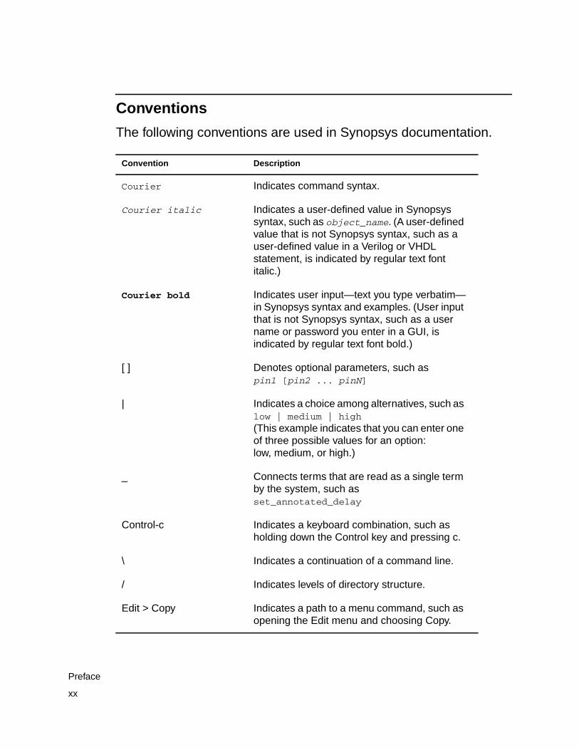
The following conventions are used in Synopsys documentation.
Convention Description
Courier Indicates command syntax.
Courier italic Indicates a user-defined value in Synopsyssyntax, such as object_name. (A user-definedvalue that is not Synopsys syntax, such as auser-defined value in a Verilog or VHDLstatement, is indicated by regular text fontitalic.)
Courier bold Indicates user input—text you type verbatim—in Synopsys syntax and examples. (User inputthat is not Synopsys syntax, such as a username or password you enter in a GUI, isindicated by regular text font bold.)
[ ] Denotes optional parameters, such aspin1 [pin2 ... pinN]
| Indicates a choice among alternatives, such aslow | medium | high(This example indicates that you can enter oneof three possible values for an option:low, medium, or high.)
_ Connects terms that are read as a single termby the system, such asset_annotated_delay
Control-c Indicates a keyboard combination, such asholding down the Control key and pressing c.
\ Indicates a continuation of a command line.
/ Indicates levels of directory structure.
Edit > Copy Indicates a path to a menu command, such asopening the Edit menu and choosing Copy.
xx
Preface
Customer Support
Customer support is available through SolvNet online customersupport and through contacting the Synopsys Technical SupportCenter.
Accessing SolvNet
SolvNet includes the Solv-It electronic knowledge base of technicalarticles and answers to frequently asked questions about Synopsystools. SolvNet also gives you access to a wide range of Synopsysonline services including software downloads, documentation on theWeb, and “Enter a Call With the Support Center.”
To access SolvNet, do the following:
1. Go to the SolvNet Web page at http://solvnet.synopsys.com.
2. If prompted, enter your user name and password. (If you do nothave a Synopsys user name and password, follow theinstructions to register with SolvNet.)
If you need help using SolvNet, click SolvNet Help in the column onthe left side of the SolvNet Web page.
xxi
Customer Support
Contacting the Synopsys Technical Support Center
If you have problems, questions, or suggestions, you can contact theSynopsys Technical Support Center in the following ways:
• Open a call to your local support center from the Web by going tohttp://solvnet.synopsys.com (Synopsys user name andpassword required), then clicking “Enter a Call to the SupportCenter.”
• Send an e-mail message to your local support center.
- E-mail [email protected] from within NorthAmerica.
- Find other local support center e-mail addresses athttp://www.synopsys.com/support/support_ctr.
• Telephone your local support center.
- Call (800) 245-8005 from within the continental United States.
- Call (650) 584-4200 from Canada.
- Find other local support center telephone numbers athttp://www.synopsys.com/support/support_ctr.
xxii
Preface
1Introduction to Formality 1
In this chapter, you are introduced to the Formality application. Itincludes the following sections:
• What Is Formality?
• How Does Formality Fit Into My Design Methodology?
• What Designs Can I Verify?
• What Pieces Make Up Formality?
• General Process Flow
• Input and Output File Types
• Concepts
1-1
What Is Formality?
Formality is an application that uses formal techniques to prove ordisprove the functional equivalence of two designs or two technologylibraries. For example, you can use Formality to compare a gate-levelnetlist to its register transfer level (RTL) source or to a modifiedversion of that gate-level netlist. After the comparison, Formalityreports whether the two designs or technology libraries arefunctionally equivalent. The Formality tool can significantly reduceyour design cycle by providing an alternative to simulation forregression testing.
The techniques Formality uses are static and do not requiresimulation vectors. Consequently, for design verification you onlyneed to provide a functionally correct, or “golden,” design (called thereference design) and a modified version of the design (called theimplementation design). By comparing the implementation designagainst the reference design, you can determine whether they arefunctionally equivalent to each other. Technology library verificationis similar except that each cell in the implementation library iscompared against each cell in the reference library one cell at a time.
Today’s design methodology requires regression testing at severalpoints in the design process. Currently, traditional simulation tools,such as event-driven and cycle-based simulators, handle thisregression testing. However, as designs become larger and morecomplex and require more simulation vectors, regression testing withtraditional simulation tools becomes a bottleneck in the design flow.The bottleneck is caused by these factors:
• Large numbers of simulation vectors are needed to provideconfidence that the design meets the required specifications.
1-2
Chapter 1: Introduction to Formality
• Logic simulators must process more events for each stimulusvector because of increased design size and complexity.
• More vectors and larger design sizes cause increased memoryswapping, slowing down performance.
Formality fits well within established electronic design automation(EDA) methodologies used to create large-scale designs, because itcan replace the traditional simulation tools used for regressiontesting. This replacement, combined with the continued use of statictiming analysis tools, gives you two distinct advantages: significantlyreduced verification times and complete verification.
Reduced verification times occur because Formality requires noinput vectors. Reducing gate-level simulation time means you canspend more time verifying the initial golden RTL design to get betterfunctional coverage. Formality maintains that coverage through allsubsequent regressions.
Complete verification, the second advantage, means 100 percentequivalence over the entire vector space. Complete verification issignificant because you no longer have to compromise the subset ofvectors for gate-level simulation.
The following list summarizes the Formality features:
• Proves two designs or technology libraries are functionallyequivalent, faster than verification using event-driven simulators.
• Provides complete verification (not vector-dependent).
• Performs RTL-to-RTL, RTL-to-gate, and gate-to-gate designverifications.
1-3
What Is Formality?
• Performs Verilog-to-database, Verilog-to-Verilog,database-to-database, Verilog-to-SPICE, anddatabase-to-SPICE technology library verifications.
• Offers diagnostic capabilities to help you locate and correctfunctional discrepancies between designs.
• Reads Synopsys internal (.db or .ddc) formats.
• Reads synthesizable SystemVerilog, Verilog, and VHDL.
• Performs automatic hierarchical verification.
• Uses existing Design Compiler technology libraries.
• Saves and restores designs and verification sessions.
• Offers a graphical user interface (GUI) and a shell command-lineinterface (fm_shell) environment.
• Verifies a wide range of design transforms or modifications,including pipeline retiming and reencoded finite state machines.
• Offers schematic views and isolated “cone of logic” views thatsupport location of design discrepancies.
How Does Formality Fit Into My Design Methodology?
For design verification, Formality fits into a design process exactlythe same way a logic simulator fits when it is used for regressiontesting. Specifically, any time you make a nonfunctional change to adesign, you can use Formality to prove that the implementationdesign is functionally equivalent to the reference design.
1-4
Chapter 1: Introduction to Formality
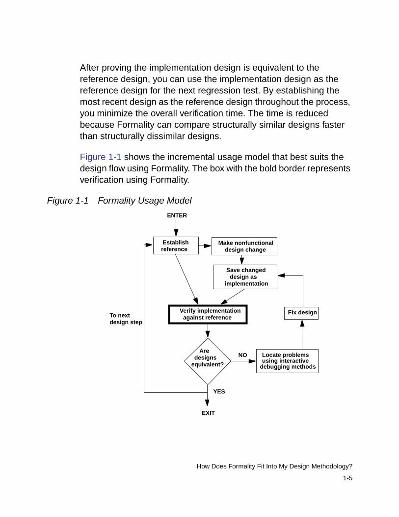
After proving the implementation design is equivalent to thereference design, you can use the implementation design as thereference design for the next regression test. By establishing themost recent design as the reference design throughout the process,you minimize the overall verification time. The time is reducedbecause Formality can compare structurally similar designs fasterthan structurally dissimilar designs.
Figure 1-1 shows the incremental usage model that best suits thedesign flow using Formality. The box with the bold border representsverification using Formality.
Figure 1-1 Formality Usage Model
Establishreference
Make nonfunctionaldesign change
Verify implementationagainst reference
Locate problemsAre
designsequivalent?
YES
NO
Save changeddesign as
implementation
ENTER
EXIT
using interactivedebugging methods
Fix designTo nextdesign step
1-5
How Does Formality Fit Into My Design Methodology?

Figure 1-2 shows how Formality fits into a typical ASIC verificationmethodology. In Figure 1-2, ovals represent data and boxesrepresent processes. Boxes with bold borders represent verificationusing Formality.
1-6
Chapter 1: Introduction to Formality
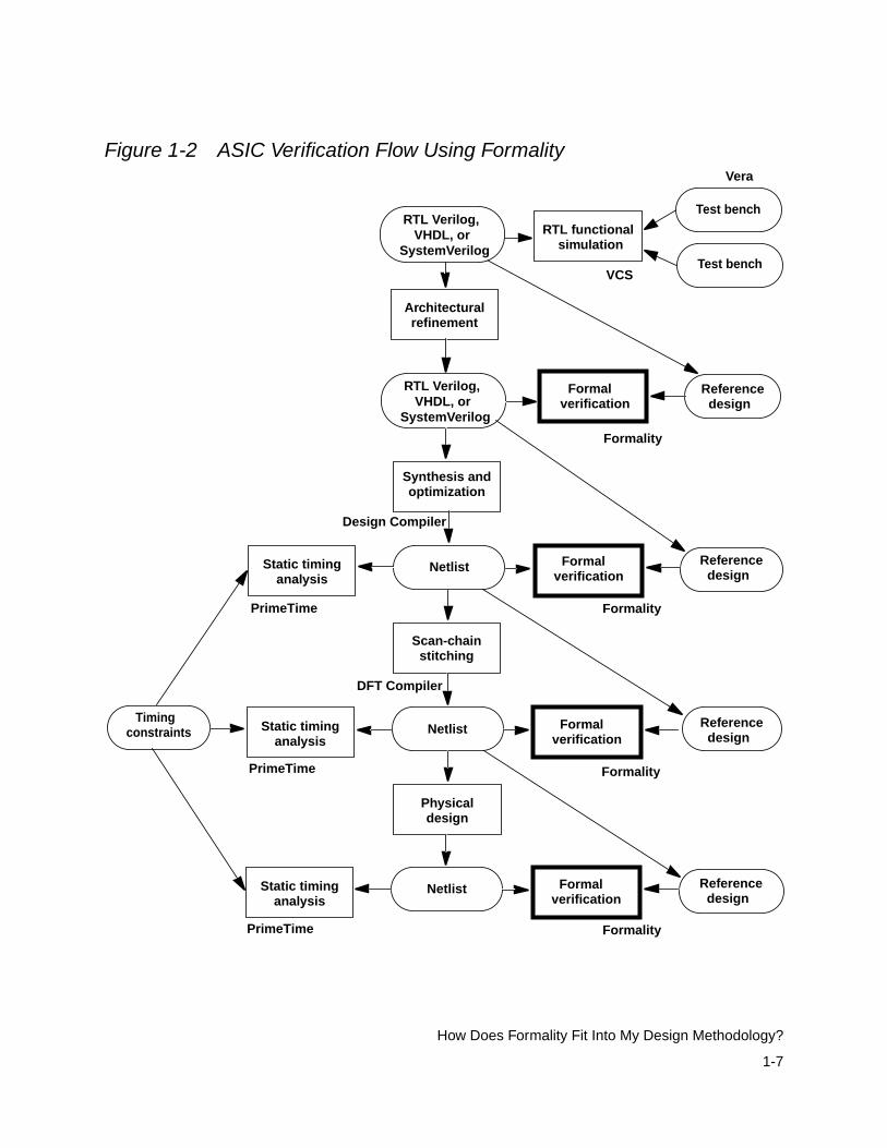
Figure 1-2 ASIC Verification Flow Using Formality
RTL functionalsimulation
Formal Referencedesign
Timingconstraints
Static timinganalysis
Netlist
Static timinganalysis
Netlist
Static timinganalysis
Netlist
Architecturalrefinement
Synthesis andoptimization
Physicaldesign
Scan-chainstitching
verification
Formalverification
Formalverification
Formalverification
Formality
Formality
Formality
Formality
Design Compiler
DFT Compiler
PrimeTime
PrimeTime
PrimeTime
Referencedesign
Referencedesign
Referencedesign
Test bench
Test benchVCS
Vera
RTL Verilog, VHDL, orSystemVerilog
RTL Verilog, VHDL, orSystemVerilog
1-7
How Does Formality Fit Into My Design Methodology?
What Designs Can I Verify?
This section presents fundamental design requirements anddescribes situations where Formality works particularly well.
Design Requirements
The reference design and implementation design that you use withFormality must meet the following fundamental requirements:
• Design files must be in the Synopsys internal database (.db or.ddc) format or must use only synthesizable SystemVerilog,Verilog, or VHDL constructs accepted by (V)HDL Compiler(Presto). Formality can also read designs in Milkyway formats.
• Designs should use a synchronous design style. They should notcontain state-holding loops implemented as combinational logic.
• Top-level I/O ports, sequential components, and black boxcomponents in both the reference design and implementationdesign must be aligned structurally. Formality automaticallymatches as many ports and components as possible betweenthe implementation design and reference design duringverification. If Formality has not automatically determined amatch, you can use commands to create these matches.
Design Types
This section presents examples of situations where Formality offersa good solution for regression testing.
1-8
Chapter 1: Introduction to Formality
Verification of Two RTL Designs
When you make an architectural change to an RTL design, useFormality to verify that you did not change how the design functions.In this situation, you are verifying an RTL implementation designagainst an original RTL reference design.
Situations where this type of regression testing becomes necessaryinclude
• Adding clock-gating circuitry for power reduction
• Restructuring critical paths
• Reorganizing logic for area reduction
Verification of an RTL Design and a Gate-Level Design
You can verify an RTL design against a gate-level design at severalpoints in the design methodology. For example, it is important toverify the gate-level implementation design that results fromsynthesis against the golden RTL design for functional equivalence.This gate-level design becomes the golden design used in verifyingsubsequent implementation designs.
Another example is when you make minor functional changes in thegate-level netlist and you simultaneously update the RTL sourcewithout using synthesis. In this case, you can use Formality to verifythat the changes made in the RTL source match the currentimplementation design.
Verification becomes important in situations such as the following:
• Maintaining the RTL design as the source design for futuredesign revisions
1-9
What Designs Can I Verify?
• Using the RTL design in system-level simulations
• Using the RTL design as the official documentation of designfunctions
• Synthesizing the RTL design
Note:Formality does not support programmable logic array (PLA),state table (.st), or equation table (.e) formats. Therefore, do notwrite your RTL to these formats when using Formality.
Verification of Two Gate-Level Designs
You can use Formality to verify the functional equivalence of thedesign when you produce a new gate-level implementation bymaking nonfunctional changes.
The following typical changes result in a new implementation design,but do not affect functional capabilities:
• Adding test logic (scan circuitry) to a design
• Reordering a scan chain in a design
• Inserting a clock tree into a design
• Adding I/O pads to the netlist
• Performing design layout
• Performing flattening and cell sizing
• Creating a netlist for hardware acceleration or emulation
1-10
Chapter 1: Introduction to Formality
What Pieces Make Up Formality?
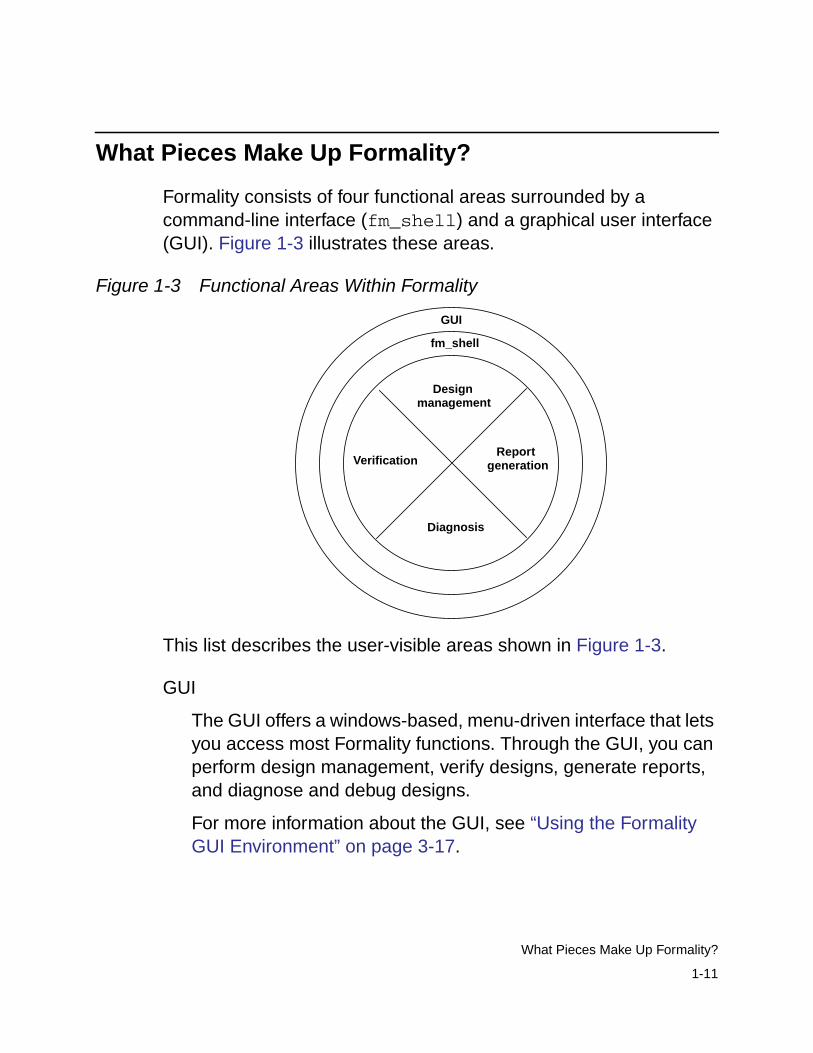
Formality consists of four functional areas surrounded by acommand-line interface (fm_shell) and a graphical user interface(GUI). Figure 1-3 illustrates these areas.
Figure 1-3 Functional Areas Within Formality
This list describes the user-visible areas shown in Figure 1-3.
GUI
The GUI offers a windows-based, menu-driven interface that letsyou access most Formality functions. Through the GUI, you canperform design management, verify designs, generate reports,and diagnose and debug designs.
For more information about the GUI, see “Using the FormalityGUI Environment” on page 3-17.
Diagnosis
Verification
GUI
fm_shell
Designmanagement
Reportgeneration
1-11
What Pieces Make Up Formality?
fm_shell
The fm_shell command-line interface offers the same commandsas the GUI and some unique functions. From fm_shell you cando everything that you can with the GUI, except view schematicrepresentations of designs and view logic cones.
For more information about shell commands, see the man pages.
Design management
The design management functions let you set up and control theverification process. For example, you can load designs,establish environmental parameters, save and restoreverification sessions, and help Formality match points in thedesigns.
For more information about design management, see Chapter 5,“Preparing the Design for Verification,” and Chapter 7,“Debugging Failed Design Verifications.”
Verification
Verification is the primary function of Formality. By default,Formality checks for design consistency when you verify a designor technology library. An implementation design is consistent witha reference design when it is functionally equivalent. Therefore,a don’t care state (X) in the reference design can be representedby either a 0 or 1 state in the implementation design.
You can also test for design or technology library equality. Animplementation design is equivalent to a reference design whenit meets both of the following requirements:
- It is consistent with the reference design.
- Its set of don’t care vectors matches that of the referencedesign set.
1-12
Chapter 1: Introduction to Formality
For more information, see “Working With Equivalences” onpage 5-25. For procedures that describe how to performverification, see Chapter 6, “Compare Point Matching andVerification.”
Diagnosis
You use the diagnosis function when design verification fails.Diagnosis produces information that helps you isolate areas inthe design that could cause a failed verification. For moreinformation, see Chapter 7, “Debugging Failed DesignVerifications.”
Report generation
Formality allows you to generate several types of reports. Thesereports provide information about the most recent verification,most recent diagnosis, environment parameters, or parametersthat affect a particular design.
General Process Flow
The flow chart in Figure 1-4 provides an overall guide to theFormality design verification process. Starting with Chapter 3,“Starting Formality,” each chapter describes one or more steps indetail. This chart appears in the beginning of each applicablechapter to remind you where you are in the process.
1-13
General Process Flow
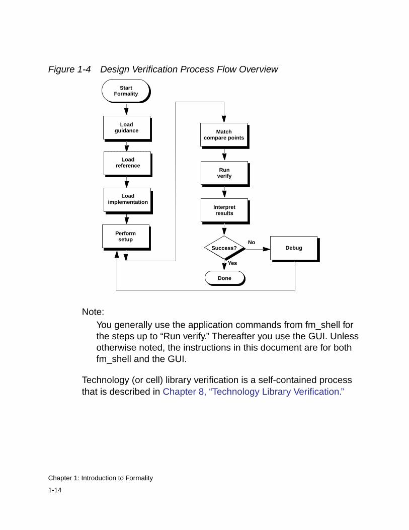
Figure 1-4 Design Verification Process Flow Overview
Note:You generally use the application commands from fm_shell forthe steps up to “Run verify.” Thereafter you use the GUI. Unlessotherwise noted, the instructions in this document are for bothfm_shell and the GUI.
Technology (or cell) library verification is a self-contained processthat is described in Chapter 8, “Technology Library Verification.”
Interpretresults
Performsetup
Runverify
Success?No
Yes
Done
Matchcompare points
Loadreference
Loadimplementation
Debug
StartFormality
Loadguidance
1-14
Chapter 1: Introduction to Formality
Input and Output File Types
This section describes the types of files that the Formality toolaccepts and generates for design verification. It includes thefollowing sections:
• Input
• Output
• Synopsys Setup File
Input
Formality accepts several types of files as input. File formats consistof files that are specific to Formality and design formats. Figure 1-5illustrates Formality input.
1-15
Input and Output File Types
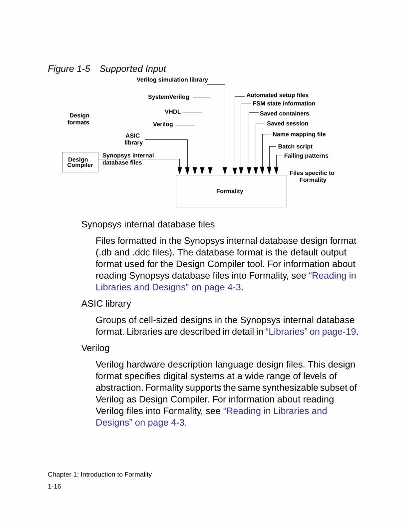
Figure 1-5 Supported Input
Synopsys internal database files
Files formatted in the Synopsys internal database design format(.db and .ddc files). The database format is the default outputformat used for the Design Compiler tool. For information aboutreading Synopsys database files into Formality, see “Reading inLibraries and Designs” on page 4-3.
ASIC library
Groups of cell-sized designs in the Synopsys internal databaseformat. Libraries are described in detail in “Libraries” on page-19.
Verilog
Verilog hardware description language design files. This designformat specifies digital systems at a wide range of levels ofabstraction. Formality supports the same synthesizable subset ofVerilog as Design Compiler. For information about readingVerilog files into Formality, see “Reading in Libraries andDesigns” on page 4-3.
Design
Formality
Saved containers
ASIC
Failing patterns
Batch script
Name mapping file
Saved sessionDesign
formats
library
Files specific toFormality
FSM state information
Compiler
Automated setup files
Synopsys internaldatabase files
Verilog
SystemVerilog
Verilog simulation library
VHDL
1-16
Chapter 1: Introduction to Formality
VHDL
VHDL design files. This design format specifies digital systems ata high level of abstraction. For information about reading VHDLfiles into Formality, see “Reading in Libraries and Designs” onpage 4-3.
SystemVerilog
SystemVerilog design files. This design format specifies digitalsystems at a wide range of levels of abstraction. For informationabout reading SystemVerilog files into Formality, see “Reading inLibraries and Designs” on page 4-3.
Verilog simulation library
Verilog simulation library files. You can read the cell definitioninformation into a technology library. The library reader extractsthe pertinent information to determine the gate-level behavior ofthe design, and generates a netlist that represents thefunctionality of the Verilog library cells. Libraries are described indetail in “Libraries” on page 1-19.
Automated setup files
Setup information in the form of guidance or automated setupfiles to help Formality understand and verify the transformationsbetween designs. Automated setup files are described in detail in“Working With Automated Setup Files” on page 5-72.
FSM state information
A file that contains flip-flop names and their encoding for finitestate machines (FSMs). This file defines FSMs so that Formalitycan create the compare points necessary for verification. Forinformation about reading these types of files, see “Working WithReencoded Finite State Machines” on page 5-53.
1-17
Input and Output File Types
Saved containers
The Formality internal representation of a container and itscontents. You supply this file when you want to restore apreviously saved container. For information about savingcontainers, see “Saving the Entire Formality Session” onpage 5-86.
Saved session
A file that contains the state of the verification session. Yousupply this file when you want to restore a previously savedFormality session. For information about restoring a Formalitysession, see “Restoring a Session” on page 5-89.
Name mapping file
A file that contains one-to-one name mappings that Formalityapplies to specific designs. Formality performs a verificationbased on compare points composed of comparable designobjects. Sometimes the naming scheme for design objects in animplementation design deviates measurably from that of thereference design. In such cases, a mapping file can be used tomatch the design objects. For information about mapping namesbetween designs, see “Unmatched Points” on page 7-15.
Batch script
A file that contains Formality shell commands. BecauseFormality supports batch mode operation, you can supply a filethat contains valid Formality shell commands to direct theverification process. For information about preparing a batchscript, see “Using Batch Jobs” on page 6-31.
1-18
Chapter 1: Introduction to Formality
Failing patterns
A file that contains failing input vectors for the most recent failedverification or diagnosis, or the most recent application of a set ofpreviously saved failing patterns. Formality uses this file as inputwhen simulating previously failing patterns. For information aboutsimulating patterns, see “Running Previously Saved FailingPatterns” on page 7-48.
Libraries
Libraries are collections of designs. When you read design data intoFormality, it is grouped into libraries. Formality supports two types oflibraries: design libraries and technology libraries.
Design library
A collection of designs usually associated with a single designeffort. For example, a design library might contain individualdesigns that represent the parts of a hierarchical design: core,control_block, mux_out, and mux_in. Depending on the size andcomplexity of the top-level design, it might be better to use morethan one design library to organize the design data.
Technology library
A collection of cells usually associated with a particular vendorand design technology. For example, when you create a newcontainer in Formality, it automatically loads in the generictechnology (GTECH) library. There are two types of technologylibraries: shared and unshared. Shared technology libraries arevisible in every container and are automatically loaded into everycontainer subsequently created during the Formality session.Unshared technology libraries are loaded into a particularcontainer.
1-19
Input and Output File Types
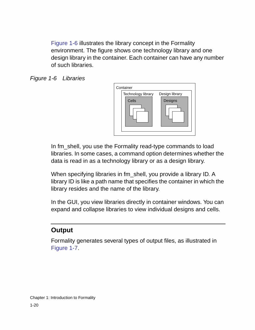
Figure 1-6 illustrates the library concept in the Formalityenvironment. The figure shows one technology library and onedesign library in the container. Each container can have any numberof such libraries.
Figure 1-6 Libraries
In fm_shell, you use the Formality read-type commands to loadlibraries. In some cases, a command option determines whether thedata is read in as a technology library or as a design library.
When specifying libraries in fm_shell, you provide a library ID. Alibrary ID is like a path name that specifies the container in which thelibrary resides and the name of the library.
In the GUI, you view libraries directly in container windows. You canexpand and collapse libraries to view individual designs and cells.
Output
Formality generates several types of output files, as illustrated inFigure 1-7.
Cells
Technology library
Container
Designs
Design library
1-20
Chapter 1: Introduction to Formality
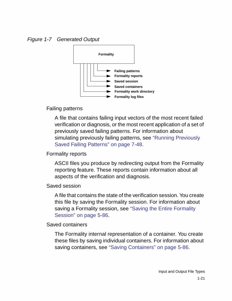
Figure 1-7 Generated Output
Failing patterns
A file that contains failing input vectors of the most recent failedverification or diagnosis, or the most recent application of a set ofpreviously saved failing patterns. For information aboutsimulating previously failing patterns, see “Running PreviouslySaved Failing Patterns” on page 7-48.
Formality reports
ASCII files you produce by redirecting output from the Formalityreporting feature. These reports contain information about allaspects of the verification and diagnosis.
Saved session
A file that contains the state of the verification session. You createthis file by saving the Formality session. For information aboutsaving a Formality session, see “Saving the Entire FormalitySession” on page 5-86.
Saved containers
The Formality internal representation of a container. You createthese files by saving individual containers. For information aboutsaving containers, see “Saving Containers” on page 5-86.
Formality
Saved containers
Saved session
Formality reportsFailing patterns
Formality work directory
Formality log files
1-21
Input and Output File Types
Formality work directory
The Formality work directory named FM_WORK. Formalitycreates this directory upon invocation. It contains containers andshared technology libraries.
Formality log files
Formality maintains two log files: formality.log andfm_shell_command.log. The formality.log file contains verboseinformation not printed to the transcript. For example, duringverification the transcript might print an informational messageindicating that constants were propagated in the referencedesign and directing you to the formality.log file for moreinformation. The fm_shell_command.log file contains a history ofFormality shell commands run during the session.
If multiple sessions of Formality are running, the workingdirectory and log files are named using the following scheme,where n is an integer value:
FM_WORKnformalityn.logfm_shell_commandn.log
Note:
Exiting abnormally from Formality can clutter your file systemwith locked files associated with Formality logs and with theFormality working directory. You can safely delete these fileswhen the Formality session associated with them is no longerrunning.
1-22
Chapter 1: Introduction to Formality
Controlling File Names Generated by Formality
Formality allows you to control the naming of its files and directorynames. These names can be appended with a unique suffix for eachverification run.
Specifying a unique name can be useful for correlating the Formalitytranscript with the Formality log file when you run multipleverifications within the same directory.
Use the fm_shell -name_suffix suffix command to specifyunique file names. Formality constructs the file names anddirectories as follows:
• formality_suffix.log
• fm_shell_command_suffix.log
• FM_WORK_suffix
In addition, the -overwrite option allows you to overwrite existingfiles. If you use the -name_suffix option, and a file with the samesuffix already exists, Formality generates an error message. If youwant to overwrite any existing files, use the -overwrite option withthe fm_shell command.
You can access (read only) the following two tool commandlanguage (Tcl) variables to see the new file names for theformality.log file and the fm_shell_command.log file:
• formality_log_name
• sh_command_log_file
1-23
Input and Output File Types
Synopsys Setup File
Each time you invoke Formality, it executes the commands in theFormality setup files, all named .synopsys_fm.setup. These setupfiles can reside in three directories that Formality reads in a specificorder. You can use these files to automatically set variables to yourpreferred settings. The following list shows the order in whichFormality reads the files:
1. Synopsys root directory. For example, if the release tree root is/usr/synopsys, the setup file is
/usr/synopsys/admin/setup/.synopsys_fm.setup
2. Your home directory. You create this .synopsys_fm.setup file, andit applies to all sessions started by you.
3. The directory where you have invoked Formality (current workingdirectory). You create this .synopsys_fm.setup file and customizeit for a particular design.
If a particular variable is set in more than one file, the last file readoverwrites the previous setting.
Concepts
This section presents key concepts that help you effectively useFormality. It includes the following sections:
• Compare Points
• Compare Rules
• Containers
1-24
Chapter 1: Introduction to Formality
• Design Equivalence
• Logic Cones
• Reference Design and Implementation Design
• Solvers
Compare Points
A compare point is a design object used as a combinational logicendpoint during verification. A compare point can be an output port,register, latch, black box input pin, or net driven by multiple drivers.
Formality uses the following design objects to automatically createcompare points:
• Primary outputs
• Sequential elements
• Black box input pins
• Nets driven by multiple drivers, where at least one driver is a portor black box
Formality verifies a compare point by comparing the logic cone froma compare point in the implementation design against a logic conefor a matching compare point from the reference design, as shownin Figure 1-8.
1-25
Concepts
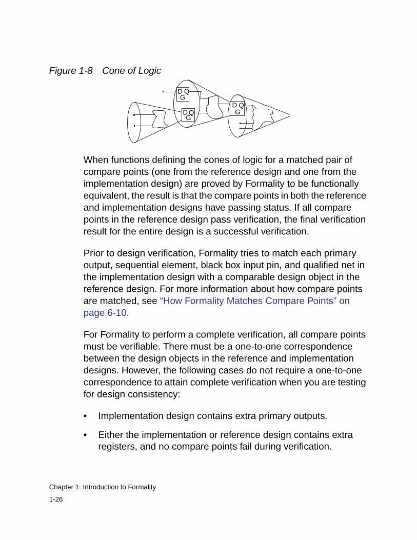
Figure 1-8 Cone of Logic
When functions defining the cones of logic for a matched pair ofcompare points (one from the reference design and one from theimplementation design) are proved by Formality to be functionallyequivalent, the result is that the compare points in both the referenceand implementation designs have passing status. If all comparepoints in the reference design pass verification, the final verificationresult for the entire design is a successful verification.
Prior to design verification, Formality tries to match each primaryoutput, sequential element, black box input pin, and qualified net inthe implementation design with a comparable design object in thereference design. For more information about how compare pointsare matched, see “How Formality Matches Compare Points” onpage 6-10.
For Formality to perform a complete verification, all compare pointsmust be verifiable. There must be a one-to-one correspondencebetween the design objects in the reference and implementationdesigns. However, the following cases do not require a one-to-onecorrespondence to attain complete verification when you are testingfor design consistency:
• Implementation design contains extra primary outputs.
• Either the implementation or reference design contains extraregisters, and no compare points fail during verification.
D QG
D QG
D QG
1-26
Chapter 1: Introduction to Formality
Compare points are primarily matched by object names in thedesigns. If the object names in the designs are different, Formalityuses various methods to match up these compare pointsautomatically. You can also manually match these object nameswhen all automatic methods fail.
Compare-point matching techniques in Formality can be broadlydivided into two categories:
• Name-based matching techniques
• Non-name-based matching techniques
For more information, see “Matching Compare Points” on page 6-3.
Unmatched design objects from either the implementation orreference design are reported as failing compare points, with a noteindicating that there is no comparable design object in the referencedesign.
Sometimes you might have to provide information so that Formalitycan match all design objects before performing verification. Forexample, the implementation and reference designs might containdesign objects that differ in name but are otherwise comparable.However, Formality is not able to match them by using its matchingalgorithms (including signature analysis). In such cases, you canmap design object names yourself using several methods. For moreinformation about matching design objects with different names, see“Unmatched Points” on page 7-15.
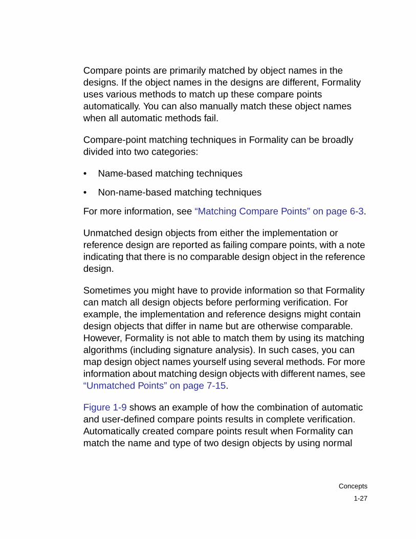
Figure 1-9 shows an example of how the combination of automaticand user-defined compare points results in complete verification.Automatically created compare points result when Formality canmatch the name and type of two design objects by using normal
1-27
Concepts
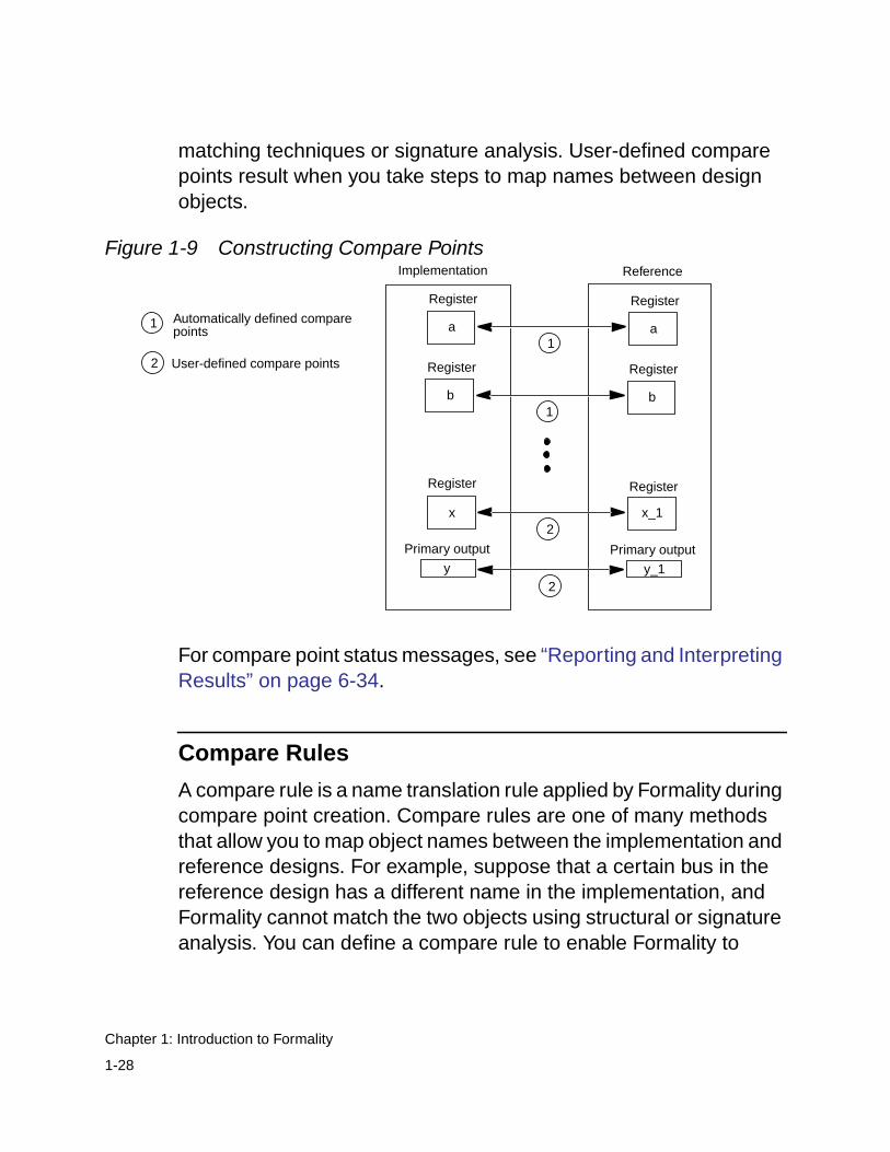
matching techniques or signature analysis. User-defined comparepoints result when you take steps to map names between designobjects.
Figure 1-9 Constructing Compare Points
For compare point status messages, see “Reporting and InterpretingResults” on page 6-34.
Compare Rules
A compare rule is a name translation rule applied by Formality duringcompare point creation. Compare rules are one of many methodsthat allow you to map object names between the implementation andreference designs. For example, suppose that a certain bus in thereference design has a different name in the implementation, andFormality cannot match the two objects using structural or signatureanalysis. You can define a compare rule to enable Formality to
Implementation Reference
Register
Primary output
a
Register
x_1
y
x
Register
a
Register
Primary output
y_1
Automatically defined comparepoints
User-defined compare points
1
2
1
2
2
b
Register
b
Register
1
1-28
Chapter 1: Introduction to Formality
correctly create compare points. Application of the compare rulemaps the bus names in the reference design to those in theimplementation.
Compare rules have a regular expression syntax identical to thatsupported by the test_compare_rule command. Therefore, youcan use the test_compare_rule command to ensure yourcompare rules behave as desired.
Containers
A container is a complete, self-contained space into which Formalityreads designs. It is typical for one container to hold the referencedesign while another holds the implementation design. In general,you do not need to concern yourself with containers. You simply loaddesigns in as either reference or implementation. This is describedin “Reading in Libraries and Designs” on page 4-3.
A container typically includes a set of related technology librariesand design libraries that fully describe a design that is to becompared against another design. A technology library is acollection of “parts” associated with a particular vendor and designtechnology. A design library is a collection of designs associated witha single design effort. Designs contain design objects such as cells,ports, nets, and pins. A cell can be a primitive or an instance ofanother design.
Figure 1-10 and Figure 1-11 illustrate the concept of containers.
1-29
Concepts
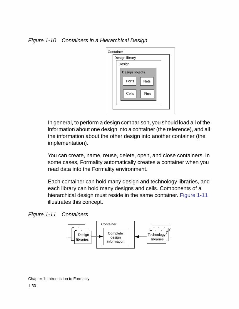
Figure 1-10 Containers in a Hierarchical Design
In general, to perform a design comparison, you should load all of theinformation about one design into a container (the reference), and allthe information about the other design into another container (theimplementation).
You can create, name, reuse, delete, open, and close containers. Insome cases, Formality automatically creates a container when youread data into the Formality environment.
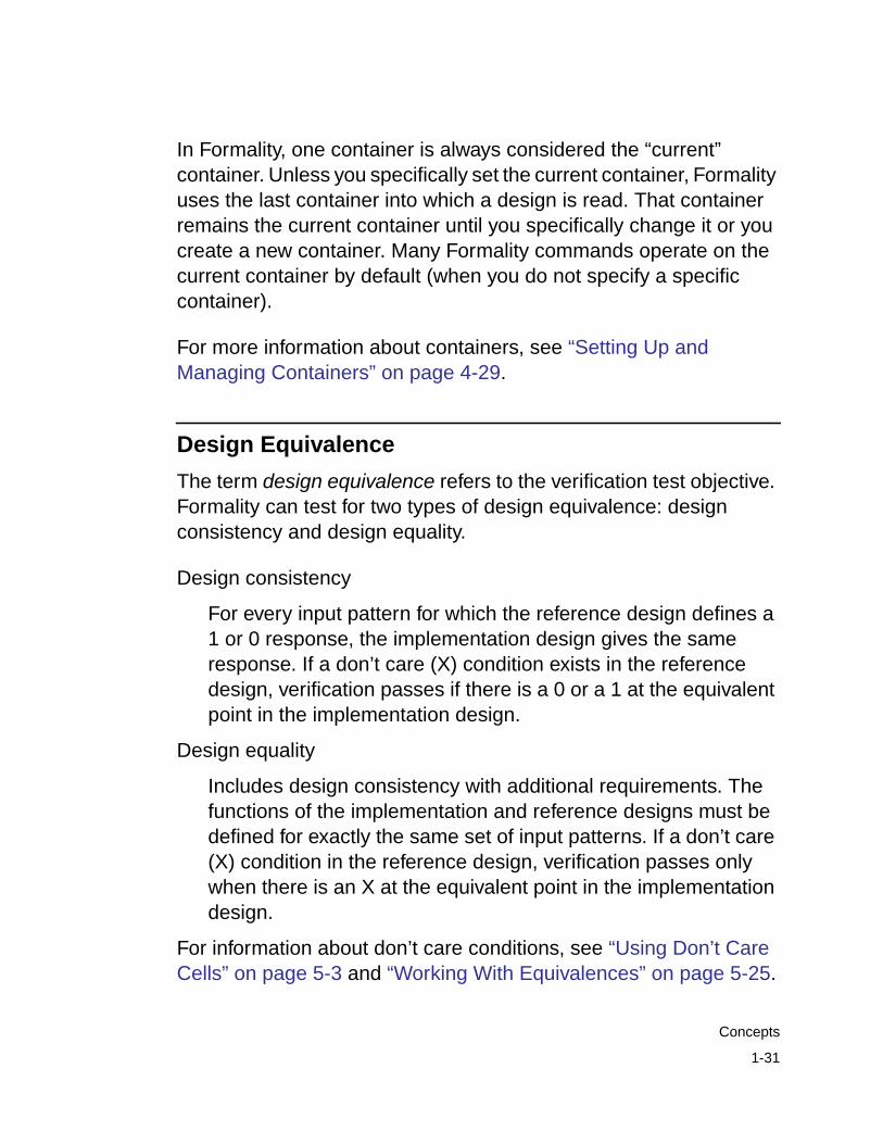
Each container can hold many design and technology libraries, andeach library can hold many designs and cells. Components of ahierarchical design must reside in the same container. Figure 1-11illustrates this concept.
Figure 1-11 Containers
Design objects
Design
Design library
Container
Cells
NetsPorts
Pins
Completedesign
information
ContainerDesignFilesDesign
Files
DesignFilesDesign
FilesDesignlibraries
TechnologyTechnology
Technologylibraries
1-30
Chapter 1: Introduction to Formality
In Formality, one container is always considered the “current”container. Unless you specifically set the current container, Formalityuses the last container into which a design is read. That containerremains the current container until you specifically change it or youcreate a new container. Many Formality commands operate on thecurrent container by default (when you do not specify a specificcontainer).
For more information about containers, see “Setting Up andManaging Containers” on page 4-29.
Design Equivalence
The term design equivalence refers to the verification test objective.Formality can test for two types of design equivalence: designconsistency and design equality.
Design consistency
For every input pattern for which the reference design defines a1 or 0 response, the implementation design gives the sameresponse. If a don’t care (X) condition exists in the referencedesign, verification passes if there is a 0 or a 1 at the equivalentpoint in the implementation design.
Design equality
Includes design consistency with additional requirements. Thefunctions of the implementation and reference designs must bedefined for exactly the same set of input patterns. If a don’t care(X) condition in the reference design, verification passes onlywhen there is an X at the equivalent point in the implementationdesign.
For information about don’t care conditions, see “Using Don’t CareCells” on page 5-3 and “Working With Equivalences” on page 5-25.
1-31
Concepts
The type of design equivalence is also called the verification mode.By default, verification mode tests for design consistency, which isadequate in most cases. For the rare occasion that it is not, you cantest for design equality.
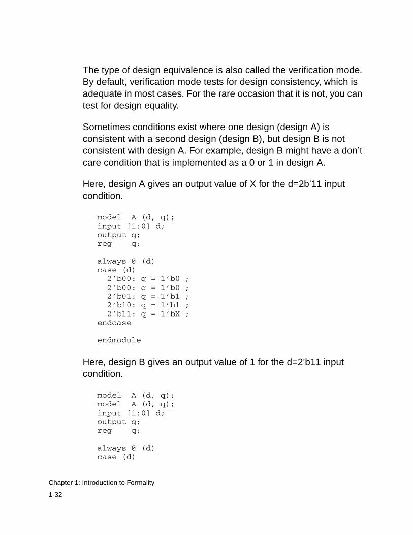
Sometimes conditions exist where one design (design A) isconsistent with a second design (design B), but design B is notconsistent with design A. For example, design B might have a don’tcare condition that is implemented as a 0 or 1 in design A.
Here, design A gives an output value of X for the d=2b’11 inputcondition.
model A (d, q);input [1:0] d;output q;reg q;
always @ (d)case (d) 2’b00: q = 1’b0 ; 2’b00: q = 1’b0 ; 2’b01: q = 1’b1 ; 2’b10: q = 1’b1 ; 2’b11: q = 1’bX ;endcase
endmodule
Here, design B gives an output value of 1 for the d=2’b11 inputcondition.
model A (d, q);model A (d, q);input [1:0] d;output q;reg q;
always @ (d)case (d)
1-32
Chapter 1: Introduction to Formality
2’b00: q = 1’b0 ; 2’b01: q = 1’b1 ; 2’b10: q = 1’b1 ; 2’b11: q = 1’b1 ;endcase
endmodule
If you run a verification with design A as the reference and design Bas the implementation, verification passes (X in the reference versus1 in the implementation). However, if you run a verification withdesign B as the reference and design A as the implementation,verification fails (1 in the reference versus X in the implementation).
Logic Cones
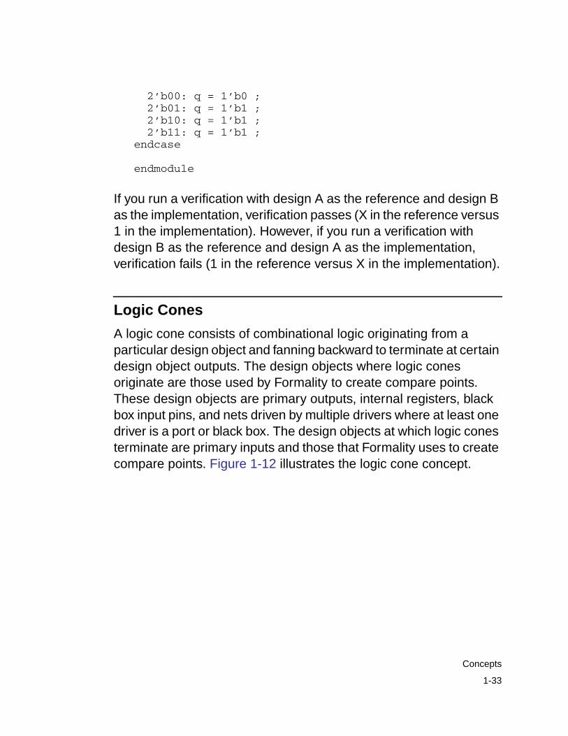
A logic cone consists of combinational logic originating from aparticular design object and fanning backward to terminate at certaindesign object outputs. The design objects where logic conesoriginate are those used by Formality to create compare points.These design objects are primary outputs, internal registers, blackbox input pins, and nets driven by multiple drivers where at least onedriver is a port or black box. The design objects at which logic conesterminate are primary inputs and those that Formality uses to createcompare points. Figure 1-12 illustrates the logic cone concept.
1-33
Concepts
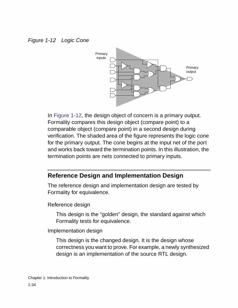
Figure 1-12 Logic Cone
In Figure 1-12, the design object of concern is a primary output.Formality compares this design object (compare point) to acomparable object (compare point) in a second design duringverification. The shaded area of the figure represents the logic conefor the primary output. The cone begins at the input net of the portand works back toward the termination points. In this illustration, thetermination points are nets connected to primary inputs.
Reference Design and Implementation Design
The reference design and implementation design are tested byFormality for equivalence.
Reference design
This design is the “golden” design, the standard against whichFormality tests for equivalence.
Implementation design
This design is the changed design. It is the design whosecorrectness you want to prove. For example, a newly synthesizeddesign is an implementation of the source RTL design.
Primaryoutput
Primaryinputs
1-34
Chapter 1: Introduction to Formality
Note:For technology library verification, the reference andimplementation definitions do not apply because you always testfor equality. In addition, you are generally specifying differenttypes of libraries against one another, for example, a synthesislibrary against a SPICE library.
After Formality proves the equivalence of the implementation designto a known reference design, you can establish the implementationdesign as the new reference design. Using this technique duringregression testing keeps overall verification times at a minimum.Conversely, working through an entire design methodology and thenverifying the sign-off netlist against the original VHDL can result indifficult verifications and in longer overall verification times.
In the fm_shell or GUI environment, you can designate a design youhave read into Formality as either the implementation or referencedesign. There are no special requirements to restrict yourdesignation. However, at any given time, you can have only oneimplementation design and one reference design in the Formalityenvironment.
Solvers
Formality enlists various solvers before and during verification toattempt to prove the equivalence or nonequivalence of two designsusing algorithms particular to the specific solver. To check forequivalence, the solvers look for internal equivalences,redundancies, constants, and so forth.
For example, the datapath solver uses a particular algorithm to solvemultipliers in the preverification stage that can significantly reducethe entire verification runtime. When the solver successfully
1-35
Concepts
preverifies a multiplier in your design, Formality converts it to a blackbox for the rest of verification. If the datapath solver is unable topreverify your multiplier, Formality returns an inconclusive result inthe transcript.
For suggestions about preparing your designs for successfulverification, see “Handling Designs When Verification Is Incomplete”on page 7-4.
1-36
Chapter 1: Introduction to Formality
2Quick Start With Formality 2
This chapter explains how to start and run Formality. The quick-starttutorial demonstrates the steps followed during a typical Formalitydesign verification session. This chapter includes the followingsections:
• Before You Start
• Invoking the Formality Shell and GUI
• Graphical User Interface
• Verifying fifo.vg Against fifo.v
• Verifying fifo_with_scan.v Against fifo_mod.vg
• Verifying fifo_jtag.v Against fifo_with_scan.v
• Debugging Using Diagnosis
• For More Information
2-1
Before You Start
Before you begin this tutorial, ensure that Formality is properlyinstalled on your system. Your .cshrc file should set the path toinclude the bin directory of the Formality installation. For example, ifyour installation directory is /u/admin/formality and your platformtype is sparcOS5, specify the set path statement, where/u/admin/formality represents the Formality installation location onyour system:
set path = ($path /u/admin/formality/bin)
You do not need a separate executable path for each platform. TheFormality invocation script automatically determines which platformyou are using and calls the correct binary. To enable the tool to dothis, however, you must make sure all platforms needed are installedin one Formality tree. Install Formality in its own directory tree,separate from other Synopsys tools such as Design Compiler.
Creating Tutorial Directories
After installing Formality, the files needed for the design examplesare located in the fm_install_path/doc/fm/tutorial directory. You mustcopy the necessary files to your home directory.
To create a tutorial directory with all of its subdirectories, do thefollowing:
1. Change to your home directory.
% cd $HOME
2. Use the following command to copy the tutorial data, wherefm_install_path is the location of the Formality software:
2-2
Chapter 2: Quick Start With Formality
% cp -r fm_install_path/doc/fm/tutorial $HOME
3. Change to the new tutorial directory.
% cd tutorial
Tutorial Directory Contents
The tutorial directory contains the following subdirectories:
• GATE: Verilog gate-level netlist.
• GATE_WITH_JTAG: Verilog gate-level netlist with scan and JointTest Action Group (JTAG) insertions.
• GATE_WITH_SCAN: Verilog gate-level netlist with scaninsertion.
• LIB: Technology library required for the gate-level netlists.
• RTL: RTL source code.
Invoking the Formality Shell and GUI
To start Formality, enter the following command at the operatingsystem prompt:
% fm_shell...fm_shell (setup)>
The fm_shell command starts the Formality shell environment andcommand-line interface. From here, start the GUI as follows:
fm_shell (setup)> start_gui
2-3
Invoking the Formality Shell and GUI
The word (setup) indicates the mode that you are currently inwhen using commands. The modes that are available are: guide,setup, match, and verify. When you invoke Formality, you begin in thesetup mode.
For more information about fm_shell and GUI environments, seeChapter 3, “Starting Formality.”
Graphical User Interface
The main GUI session window contains the following window areas,as shown in Figure 2-1 on page 2-5:
• Design bar: Displays the path for the reference andimplementation WORK libraries.
• Menu bar: GUI commands, some of which are duplicated in thetoolbar and right-click options.
• Toolbar: Easy-access options to common GUI commands. Thecontents of the toolbar change depending on the view displayedin the context pane.
• Flow-based toolbar: Options that indicate the correct flow toemploy to perform formal verification. The options becomehighlighted to indicate where you are in the flow. Each optiondisplays a new view in the context pane. By default, the GUIopens at the first step, Guidance, with the guidance work areadisplayed in the context pane.
When you use fm_shell to perform steps and then invoke theGUI, the GUI opens with the option highlighted to indicate whereyou are in the flow. This also occurs when you continue apreviously saved Formality session.
2-4
Chapter 2: Quick Start With Formality
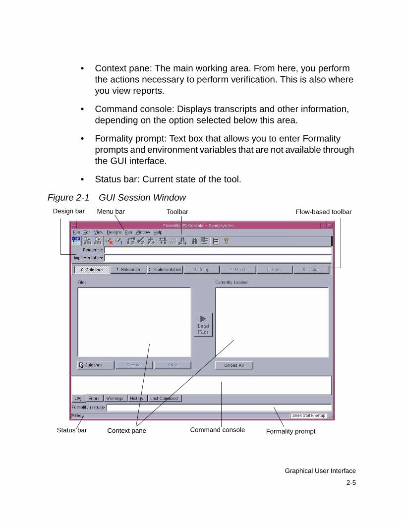
• Context pane: The main working area. From here, you performthe actions necessary to perform verification. This is also whereyou view reports.
• Command console: Displays transcripts and other information,depending on the option selected below this area.
• Formality prompt: Text box that allows you to enter Formalityprompts and environment variables that are not available throughthe GUI interface.
• Status bar: Current state of the tool.
Figure 2-1 GUI Session WindowMenu bar Toolbar Flow-based toolbar
Context pane Command console Formality prompt
Design bar
Status bar
2-5
Graphical User Interface
Verifying fifo.vg Against fifo.v
In this portion of the tutorial you verify a synthesized design namedfifo.vg, which is a pure Verilog gate-level netlist, against an RTLreference design named fifo.v.
Note:At any time, you can exit and save the current Formality sessionby selecting File > Save Session. To invoke that session again,select File > Restore Session.
Loading the Automated Setup File
Before specifying the reference and implementation designs, youcan optionally load an automated setup file (.svf) into Formality. Theautomated setup file helps Formality process design changescaused by other tools used in the design flow. Formality uses this fileto assist the compare point matching and verification process. Thisinformation facilitates alignment of compare points in the designsthat you are verifying. For each automated setup file that you load,Formality processes the content and stores the information to useduring the name-based compare point matching period.
To load the automated setup file, do the following:
1. From the Guidance tab, click Guidance, then select the file.
2. Click Load Files.
Note:If you want to pass additional constraint and nonconstraintinformation from Design Compiler to Formality, set thesynopsys_auto_setup mode before reading the automatedsetup file.
2-6
Chapter 2: Quick Start With Formality
Specifying the Reference Design
Figure 2-1 on page 2-5 shows the flow-based toolbar. The first step,which is optional, is to load the automated setup file from theGuidance tab. The next step is to load the reference. From theReference tab, you do the following:
1. Read Design Files.
2. Read DB (technology) Libraries (optional).
3. Set Top Design.
The reference design is the design against which you compare thetransformed (implementation) design. The reference design in thiscase is the RTL source file named fifo.v.
Note:Because using the Guidance tab to load the automated setup fileis optional, the tutorial skips this step.
To specify the reference design, do the following:
1. Click the Reference tab if its work area is not already displayed inthe context pane.
By default, the Read Design File tab and Verilog tab are active.
2. Click Verilog.
The Add Verilog Files dialog box appears.
3. Navigate to the RTL subdirectory where you copied the tutorialdirectory, then select the fifo.v file containing the referencedesign. Click Open.
4. Click Options.
2-7
Verifying fifo.vg Against fifo.v
The Set Verilog Read Options dialog box appears.
5. In the DesignWare root directory (hdlin_dwroot), browse to orspecify the path name to the Synopsys software root directory.
This step is necessary because fifo.v contains a DesignWareinstantiated RAM block. As needed, enter echo $SYNOPSYS atthe Formality prompt to obtain the path name of the root directory.
6. From the Options pane of the VCS Style Options tab, selectLibrary Directory (-y), and in the Enter Directory Name boxbrowse to or specify the RTL subdirectory. Click Add.
7. In the Options pane, select Library Extension (+libext), and in theEnter File Extension box, type .v. Click Add.
The -y and +libext options you selected are Verilog simulator(VCS) options, where -y specifies to look in the current directoryfor any unresolved modules and +libext specifies to look in fileswith the specified extension (.v in this case).
8. Click OK to exit the dialog box, then click Load Files.
The fifo.v file appears as the loaded reference design file.
9. Click the Set Top Design tab.
In this case, you skip the Read DB Libraries tab because the fifo.vdesign does not require a technology library. Technology librariescontain cells to which the netlist must be mapped. The fifo.vdesign does not require mapping.
10. From the Choose a library pane, select the WORK library.
This pane lists all the loaded libraries, including the DesignWare(DW*) and GTECH library, that contain the GTECH componentsrequired to map RTL.
2-8
Chapter 2: Quick Start With Formality
11. From the Choose a design pane, select fifo, the name of thetop-level design.
12. Click Set Top.
Setting the top-level design starts the linking and elaborationprocess on all files and reports if there are any missing files.Formality searches for the DesignWare RAM automatically.
Before you click Set Top, only the top-level design (fifo) is listed;the lower-level modules are not listed. The reason for this is thatduring linking, the netlist reader searches for the unresolvedmodules under the directory specified using the VCS -y option.
After you click Set Top, the choose-a-design pane lists the entiredesign hierarchy.
A green check mark appears on the Reference tab located on theflow-based toolbar, indicating that you successfully specified thereference design. You can now specify the implementation design.
Specifying the Implementation Design
The procedure for specifying the implementation design is identicalto that for specifying the reference design. From the Implementationtab, do the following:
1. Read Design Files.
2. Read DB (technology) Libraries (optional).
3. Set Top Design.
To specify the implementation design, do the following:
1. On the flow-based toolbar, click the Implementation tab.
2-9
Verifying fifo.vg Against fifo.v
By default, the Read Design File tab and Verilog tab are active.
2. Click Verilog.
The Add Verilog Files dialog box appears.
3. Navigate from the RTL directory to the GATE directory, thenselect the fifo.vg file containing the implementation design. ClickOpen.
4. Click Load Files.
The fifo.vg file appears as the loaded implementation design.
5. Click the Read DB Libraries tab, then click the DB option.
The Add DB Files dialog box appears. Unlike the fifo.v referencedesign, fifo.vg requires a technology library for mapping.
6. Navigate to the LIB directory, then select the technology librarynamed lsi_10k.db. Click Open.
7. Click Load Files.
8. Click the Set Top Design tab.
9. From the Choose a library pane, select WORK.
10. From the Choose a design pane, select the top-level design, fifo.
11. Click Set Top.
Formality links and elaborates all the files and reports if there areany missing files. Because this tutorial uses a DesignWare RAM,the tool searches for technology-dependent modules from thelsi_10k technology library.
2-10
Chapter 2: Quick Start With Formality
A green check mark appears at the Implementation option locatedon the flow-based toolbar, indicating that you successfully specifiedthe implementation design. You can go to the setup stage, asnecessary.
Setting Up the Design
You often need to specify additional setup information to account fordesigner knowledge not contained in the design netlist or to achieveoptimal performance.
This step involves supplying information to Formality. For example,you might need to set constants if the design underwenttransformations such as scan or JTAG insertion. In this case, onlyfifo.vg was synthesized; therefore, you can move on to the next step,Match.
For more information about setup possibilities, see Chapter 5,“Preparing the Design for Verification.”
Compare Point Matching
Compare point matching is the process by which Formalitysegments the reference and implementation designs into logicalunits, called logic cones. Each logic cone feeds a compare point, andeach compare point in the implementation design must match eachcompare point in the reference design or verification fails. Matchingensures that there are no mismatched logic cones and allowsFormality to proceed with verifying the implementation design forfunctionality.
2-11
Verifying fifo.vg Against fifo.v
For conceptual information about compare points, see “ComparePoints” on page 1-25. For more information about how Formalitymatches compare points, see “Matching Compare Points” onpage 6-3.
To match compare points between fifo.v and fifo.vg, do the following:
1. On the flow-based toolbar, click the Match tab.
2. Click Run Matching.
When matching is completed, the results appear in the commandconsole. You can also click the Summary tab to view the results.In this case, there are no unmatched compare points to debug.
If the summary indicated unmatched compare points, you wouldclick the Unmatched Points tab to view them. For example,unmatched compare points in the reference design mightindicate extra registers that were optimized away duringsynthesis. If you expect optimizations, you can ignore the extra(unmatched) compare points in the reference design.
3. Click OK to close the Information dialog box.
For more information about compare point matching, including howto debug unmatched compare points, see Chapter 6, “ComparePoint Matching and Verification,” and Chapter 7, “Debugging FailedDesign Verifications.”
Verifying the Designs
You are now ready to verify the features of fifo.vg against itsreference design, fifo.v.
2-12
Chapter 2: Quick Start With Formality
To verify fifo.vg against fifo.v, do the following:
1. On the flow-based toolbar, click the Verify tab.
2. Click Verify.
Verification begins, as shown by the scrolling transcript in thecommand status area. Verification fails, meaning that theimplementation design, fifo.vg, was transformed duringsynthesis, rendering it unequivalent to the reference design,fifo.v.
3. Click OK to close the dialog box notifying you of the failedverification.
In this case, verification fails. This test case includes a deliberatedesign error to introduce you to the debug capabilities of Formality.
Debugging
The challenge for most users is debugging failed verifications. Thatis, you must find the exact points in the designs that exhibit thedifference in functionality and then fix them.
To debug the implementation design, fifo.vg, do the following:
1. On the flow-based toolbar, click the Debug tab, if it is not alreadyselected.
The context pane displays the Failing Points report. Groups offailing points with similar names might appear, except for the lastelements. For example, you might see *_[reg0], *_[reg1],*_[reg2], and *_[reg3]. Typically, a group of failing points iscaused by a single error.
2. To run diagnosis on the failing points, click Diagnose.
2-13
Verifying fifo.vg Against fifo.v
During diagnosis, Formality analyzes a set of compare pointsand finds the error candidates. When Formality completes thediagnosis run, the Error Candidates window appears displayingthe error candidates found in your design.
Note:
Although this is not shown in this tutorial, if while debuggingyou get an error stating there was a diagnosis failure due to toomany errors (and you know the error is not caused by setupproblems), select a group of failing points with similar namesand click Diagnose Selected Points. This might help to directdiagnosis down to a specific section of the design.
3. From the Error Candidates Window, right-click on the error U81and select View Logic Cones.
You see a list of related failing points for that error, from which youselect one of those points (for this example, use push_logic/pop_count_svd_reg[0]) and then double-click it to bring up thelogic cone.
The Cone Schematics window appears displaying reference (topscreen) and implementation (bottom screen) schematics for thelogic cone. It highlights and zooms to the error candidate inverter,U81, in the implementation cone. The reference schematichighlights the matching region corresponding to the errorcandidate in the implementation design.
The error candidate is highlighted in orange. The correspondingmatching region in the reference design is highlighted in yellow.To view the error region in isolation, click Isolate Error CandidatePruning Mode in the cone view. This prunes away all the logicand shows the error inverter.
2-14
Chapter 2: Quick Start With Formality
Colors in the schematics window have different meaningsdepending on the color mode selected. The color modes arenone (the default), constants, simulation values, and errorcandidates.
- None – The default color mode.
- Constants – Nets with a constant logic value 0 are blue, netswith logic 1 are orange, and the remaining nets are gray. Theremaining objects are colored in the default color mode.
- Simulation values – Nets with simulation logic 0 are blue, netswith simulation logic 1 are orange, and the remaining objectsare colored in the default color mode.
- Error candidates – Error drivers corresponding to the errorcandidates are highlighted orange. The correspondingmatching region is highlighted in yellow.
4. Observe the patterns annotated on the CLK net. The referencedesign shows logic 0, while the implementation design showslogic 1.
To discover the cause for this functional difference, do thefollowing:
- Select the net in the implementation design.
- Right-click and select Isolate Subcone.
- Select the net in the reference design.
- Right-click and select Isolate Subcone.
The screens change to display just the net in question. Noticethat the logic driving the implementation CLK pin includes aninverter. During synthesis an inverter might have been insertedto fix hold time problems.
2-15
Verifying fifo.vg Against fifo.v
You can zoom in by clicking the Zoom In Tool toolbar option andthen clicking in the schematic. Deselect the option to return to thepointer.
You can copy selected objects in design and cone schematics.From the context pane, you can highlight the object, select Edit,then selecting Copy Name, Copy Reference Name, or CopyImplementation Name. You can paste these names into theFormality prompt or any other editable text box by pressingControl-v or by right-clicking the mouse and choosing Paste.
5. Fix the error by editing the netlist or resynthesizing the design togenerate a new netlist free of errors in clock tree manipulations.
The fifo_mod.vg file in the GATE directory contains the correctednetlist. Execute the following command at the Formality promptto view the difference:
% diff fifo.v fifo.mod.vg
You can see that the modified netlist removes the inverter.
6. After closing the Cone Schematics window, verify the correctedimplementation design, fifo_mod.vg, against the referencedesign. First, specify fifo_mod.vg again as the newimplementation design as follows:
- On the flow-based toolbar, click Implementation.
- From the Read Design Files tab, click the Verilog tab, then clickthe Verilog option.
- Click Yes to remove the current implementation design data.
2-16
Chapter 2: Quick Start With Formality
Note:
Clicking Yes permanently removes the currentimplementation design data. In practice, you should save thedata prior to specifying a new implementation (or reference)design.
- Navigate to the GATE subdirectory, and select the fifo_mod.vgfile.
- Click Open.
- Click Load Files.
Skip the Read DB Libraries tab because the technology libraryis shared.
- Click the Set Top Design tab.
- Make sure that WORK and fifo are selected and click Set Top.
7. As before, skip the Setup step. In this case, you can also skip theMatch step because you did not change the setup, which couldalter compare points, and you did not appreciably change theimplementation design by removing the inverter. In addition, youknow that all the compare points matched previously.
8. From the Verify tab, click Verify.
Formality performs automatic compare point matching prior toverification when you do not perform the Match step beforehand.Verification is successful.
Now that you have completed this section of the tutorial, prepare theGUI as follows for the next section:
1. From the Designs menu, select Remove Reference, then clickYes.
2-17
Verifying fifo.vg Against fifo.v
2. From the Designs menu, select Remove Implementation, thenclick Yes.
Note:
Clicking Yes permanently removes the current reference andimplementation data. In practice, be sure to save (as necessary)prior to removing design data.
3. At the Formality prompt, enter the following command:
remove_library -all
The transcript says “Removed shared technology library‘LSI_10K’.”
You now have the equivalent of a fresh session with which toexecute the next section of the tutorial.
Verifying fifo_with_scan.v Against fifo_mod.vg
Note:At any time, you can exit and save the current Formality sessionby selecting File > Save Session. To invoke that session again,select File > Restore Session.
2-18
Chapter 2: Quick Start With Formality
In this portion of the tutorial, you specify the successfully verifiednetlist, fifo_mod.vg, as the reference design. You then verify a designthat went through a design transformation against it. Thefifo_with_scan.v implementation design, as the name suggests, hadscan logic inserted.
To go through the verification steps (reference, implementation,setup, match, verify, and debug) in one continuous flow, do thefollowing:
1. On the flow-based toolbar, click the Reference tab.
By default, the Read Design File tab and Verilog tab are active.
2. Click Verilog.
3. Navigate to the fifo_mod.vg file in the GATE directory, click Open,then click Load Files.
4. Click the Read DB Libraries tab and make sure that the “Read asa shared library” option is selected.
Because this is a gate-to-gate verification, the technology libraryneeds to be available for both fifo_mod.vg and fifo_with_scan.v.By default, DB technology libraries are shared.
If you use a Verilog or VHDL technology library, you must specifythe read_verilog -tech or read_vhdl -tech command atthe Formality prompt, because they are not shared libraries.
5. Click DB, then navigate to the technology library namedlsi_10k.db in the LIB directory.
6. Click Open.
7. Click Load Files.
2-19
Verifying fifo_with_scan.v Against fifo_mod.vg
8. Click the Set Top Design tab and ensure that the fifo designinside the WORK library is selected as the top-level design.
9. Click Set Top.
Next you specify the implementation design, a procedure similarto the one described in “Specifying the Implementation Design”on page 2-9.
10. On the flow-based toolbar, click the Implementation tab.
The Read Design Files and Verilog tab are selected by default.
11. Click Verilog.
12. In the Add Verilog Files dialog box, navigate to thefifo_with_scan.v design file located in the GATE_WITH_SCANdirectory. Click Open.
13. Click Load Files.
14. Click the Set Top Design tab and make sure that the fifo designinside the WORK library is selected as the top-level design.
15. Click Set Top.
You skipped the Read DB Libraries step because you hadpreviously specified lsi_10k.db as a shared technology library.
16. Click the Setup tab.
Unlike the verification you performed between fifo.vg and fifo.v, inwhich you skipped the setup phase, the implementation designyou just specified must have its inserted scan disabled prior toverification.
17. Click the Constants tab, then click Set.
2-20
Chapter 2: Quick Start With Formality
The Set Constant dialog box appears. It lists all the input, output,and bidirectional ports within the fifo_with_scan.v design file.
18. Click the Implementation tab and make sure that fifo is selectedand that Ports appears in the drop down box near the top of thedisplay area.
19. Scroll or search for the port named test_se and select it.
You can use the Search text box to locate the signal you want tochange.
20. In the Constant Value area at the bottom of the dialog box, select0, then click OK.
Setting the test signal, test_se, to a constant zero state disablesthe scan logic in the fifo_with_scan.v design file. Notice thattest_se now appears in the Command console.
21. On the flow-based toolbar, click the Match tab, then click RunMatching.
Matching yields one unmatched compare point that you need toanalyze and fix, if necessary.
22. Click OK to remove the Information dialog box, then select theUnmatched Points tab.
You see a report on the unmatched point, test_se. It is an extracompare point in the implementation design, related to theinserted scan that you previously disabled. In this case, extracompare points are expected in the implementation design.Therefore, you can ignore them and continue to the verificationprocess.
2-21
Verifying fifo_with_scan.v Against fifo_mod.vg
Note:
Extra compare points in the reference design are not expected.Therefore, you must debug them as outlined in “Debugging” onpage 2-13.
23. On the flow-based toolbar, click the Verify tab, then click Verify.
The verification is successful. The scan insertion did not alter theimplementation design features. However, if you had not disabledthe test signal test_se in step 19, verification would have failed.
Now that you have completed this section of the tutorial, prepare theGUI as follows for the next section:
1. From the Designs menu, select Remove Reference, then clickYes.
2. From the Designs menu, select Remove Implementation, thenclick Yes.
Note:
Clicking Yes permanently removes the current reference andimplementation data. In practice, be sure to save (as necessary)prior to removing design data.
3. At the Formality prompt, enter the following command:
remove_library -all
The transcript says “Removed shared technology library‘LSI_10K’.”
You now have the equivalent of a fresh session with which toexecute the next section of the tutorial.
2-22
Chapter 2: Quick Start With Formality
Verifying fifo_jtag.v Against fifo_with_scan.v
Next, you specify the successfully verified scan-inserted netlist,fifo_with_scan.v, as the reference design. You then verify a designthat went through a different type of design transformation against it.The fifo_jtag.v implementation design includes a JTAG insertion anda scan insertion.
To go through the verification steps (reference, implementation,setup, match, verify, and debug) in one continuous flow, do thefollowing:
1. On the flow-based toolbar, click the Reference tab.
By default, the Read Design File tab and Verilog tab are active.
2. Click Verilog.
The Add Verilog Files dialog box appears.
3. Navigate to the fifo_with_scan.v file in the GATE_WITH_SCANdirectory, highlight it, and click Open.
4. Click Load Files.
5. From the Read DB Libraries tab, make sure that the “Read as ashared library” option is selected.
Because this is a gate-to-gate verification, the technology libraryneeds to be available for both the fifo_with_scan.v and fifo_jtag.vfiles.
6. Click DB, then navigate to and highlight the technology libraryfile, lsi_10k.db, in the LIB directory. Click Open.
7. Click Load Files.
2-23
Verifying fifo_jtag.v Against fifo_with_scan.v
8. From the Set Top Design tab, make sure that the fifo designinside the WORK library is selected as the top-level design, thenclick Set Top.
9. On the flow-based toolbar, click the Implementation tab.
10. From the Verilog tab, click Verilog.
The Add Verilog Files dialog box appears.
11. Navigate to the fifo_jtag.v design file located in theGATE_WITH_JTAG directory, highlight it, and click Open.
12. Click Load Files.
13. From the Set Top Design tab, ensure that the fifo design insidethe WORK library is selected as the top-level design and click SetTop.
Notice that because of the inserted JTAG modules listed at thetop of the choose-a-design pane, you might need to scroll downto find the fifo design.
Note:
If you accidentally set the wrong design as the top-level design,you must redefine the implementation (or reference) design byfirst removing the reference and implementation designs andstarting again.
You skipped the Read DB Libraries step because you hadpreviously specified lsi_10k.db as a shared technology library.
14. On the flow-based toolbar, click the Setup tab.
2-24
Chapter 2: Quick Start With Formality
For this verification you must disable the scan in fifo_with_scan.vjust as you did in the previous section of the tutorial. Rememberthat this design is now the reference design. You must alsodisable JTAG signals in the implementation design.
15. From the Constants tab, click Set.
The Set Constant dialog box appears with the Reference tabselected.
16. Make sure that fifo is selected and that Ports appears in the dropdown box near the top of the display area.
17. Scroll or search for the port named test_se and select it.
You can use the Search text box to locate the signal you want tochange.
18. In the Constant Value area at the bottom of the dialog box, select0 and click Apply.
19. Click the Implementation tab and make sure that fifo is selectedand that Ports appears in the drop down box near the top of thedisplay area.
20. Repeat steps 17 and 18 to disable the test_se test signal for theimplementation design.
21. In a similar process, disable the JTAG signals, jtag_trst, andjtag_tms, by setting them to constant 0. Click OK to close thedialog box.
The Constants report lists the four disabled signals, one for thereference design and three for the implementation design.
22. On the flow-based toolbar, select the Match tab and then clickRun Matching.
2-25
Verifying fifo_jtag.v Against fifo_with_scan.v
Matching yields 171 unmatched compare points that you mustanalyze and fix, if necessary.
23. Click OK to close the Information dialog box.
24. From the Unmatched Points tab, evaluate the compare points.
You see that the extra compare points are located in theimplementation design and related to the inserted JTAG that youpreviously disabled. Specifically, JTAG insertion results in theaddition of a large logic block called a tap controller. Therefore,extra compare points are expected in the implementation design.You can ignore them and move on to verification.
25. On the flow-based toolbar, click the Verify tab, then click Verify.
The verification is successful. The JTAG insertion did not alter theimplementation design features.
Debugging Using Diagnosis
In some designs, you can reach a point where you have fixed allsetup problems in your design or determined that no setup problemsexist. Therefore, the failure must have occurred because Formalityfound functional differences between the implementation andreference designs.
Use the following steps to isolate the problem (this section assumesyou are working in the GUI).
1. On the flow-based toolbar, click the Debug tab.
2. Click the Failing Points tab to view the failing points.
2-26
Chapter 2: Quick Start With Formality
During verification, Formality creates a set of failing patterns foreach failing point. These patterns show the differences betweenthe implementation and reference designs. Diagnosis is theprocess of analyzing these patterns and identifying errorcandidates that might be responsible for the failure. Sometimesthe design can have multiple errors and, therefore, an errorcandidate can have multiple locations.
3. Run a diagnosis on all of the failing points listed in this window byclicking Diagnose.
Note:
After clicking Diagnose, you might get a warning (FM-417)stating that too many error locations caused the diagnosis tofail (if the error locations exceed five). If this occurs and youhave already verified that no setup problems exist, select agroup of failing points (such as a group of buses with commonnames), and click Diagnose Selected Points. This can help thediagnosis by paring down the failing points to a specific sectionin the design. Finally, if the group diagnosis fails, select a singlefailing point and run the selected diagnosis.
When the diagnosis is complete, the Error Candidate windowappears.
4. Click the Error Candidates tab to view the error candidates.
You see a list of error candidates in this window. An errorcandidate can have multiple distinct errors associated with it. Foreach of the errors, the number of related failing points is reported.
There can be alternate error candidates apart from therecommended ones shown in this window. You can inspect thealternate candidates by using Next and Previous. You can
2-27
Debugging Using Diagnosis
reissue the error candidate report anytime after running thediagnosis by using the report_error_candidatescommand.
5. Select an error with the maximum number of failing points.Right-click that error, then select View Logic Cones.
If there are multiple failing points, a list appears, from which youcan choose a particular failing point to view. Errors are the driversto the design whose function can be changed to fix the failingcompare point.
The schematic shows the error highlighted in the implementationdesign along with the associated matching region of thereference design.
Note:
Changing the function of an error location can sometimescause previously passing input patterns to fail.
Examine the logic cone for the driver causing the failure. theproblem driver is highlighted in orange. To view the error regionin isolation, click Isolate Error Candidates Pruning Mode. You canalso prune the associated matching region of the referencedesign. You can undo this pruning mode by choosing the Undooption from the Edit menu.
Note:
You can employ the previous diagnosis method by setting thediagnosis_enable_error_isolation variable to falseand then rerunning the verification.
2-28
Chapter 2: Quick Start With Formality
For More Information
For more information about each stage of the formal verificationprocess demonstrated in the tutorial, see the following chapters:
• Chapter 3, “Starting Formality,” which describes the userinterfaces and describes how to invoke the tool.
• Chapter 4, “Setting Basic Elements for Design Verification,”which describes how to read in designs and libraries, and how todefine the reference and implementation designs.
• Chapter 5, “Preparing the Design for Verification,” whichdescribes how to set design-specific parameters to helpFormality perform verification and to optimize your design forverification.
• Chapter 6, “Compare Point Matching and Verification,” whichdescribes how to match compare points and perform verification.
• Chapter 7, “Debugging Failed Design Verifications,” whichdescribes diagnostic procedures that can help you locate areasin the design that caused failure.
• Chapter 8, “Technology Library Verification,” which describeshow to compare two technology libraries.
• Appendix A, “Appendix A - Tcl Syntax as Applied to FormalityShell Commands,” which describes Tcl syntax as it relates tomore advanced tasks run from fm_shell. Topics includeapplication commands, built-in commands, procedures, controlflow commands, and variables.
• Appendix B, “Appendix B - Formality Library Support,” whichdescribes how to verify and modify technology libraries to makethem suitable for Formality to perform equivalence checking.
2-29
For More Information

• Appendix C, “Appendix C - Reference Lists,” which providesreference tables listing Formality application commands andenvironment variables.
2-30
Chapter 2: Quick Start With Formality
3Starting Formality 3
Formality offers two working environments: the Formality shell (acommand-line-based user interface) and the Formality GUI (agraphical windows-based interface). This chapter describes how toinvoke these environments and how to use interface elements, suchas the command log file and the help facility.
This chapter includes the following sections:
• Invoking Formality
• Formality Shell Environment
• Using the Formality GUI Environment
• General Formality Usage Options
Figure 3-1 outlines the design verification process flow for Formality.This chapter focuses on how to start Formality.
3-1
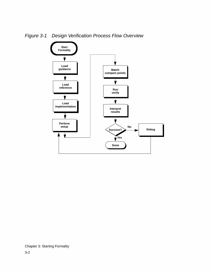
Figure 3-1 Design Verification Process Flow Overview
Interpretresults
Performsetup
Runverify
Success?No
Yes
Done
Matchcompare points
Loadreference
Loadimplementation
Debug
StartFormality
Loadguidance
Debug
3-2
Chapter 3: Starting Formality
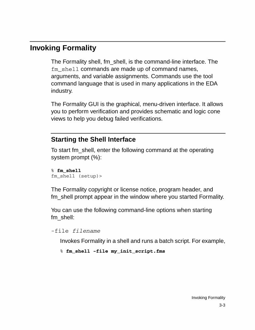
Invoking Formality
The Formality shell, fm_shell, is the command-line interface. Thefm_shell commands are made up of command names,arguments, and variable assignments. Commands use the toolcommand language that is used in many applications in the EDAindustry.
The Formality GUI is the graphical, menu-driven interface. It allowsyou to perform verification and provides schematic and logic coneviews to help you debug failed verifications.
Starting the Shell Interface
To start fm_shell, enter the following command at the operatingsystem prompt (%):
% fm_shellfm_shell (setup)>
The Formality copyright or license notice, program header, andfm_shell prompt appear in the window where you started Formality.
You can use the following command-line options when startingfm_shell:
-file filename
Invokes Formality in a shell and runs a batch script. For example,
% fm_shell -file my_init_script.fms
3-3
Invoking Formality
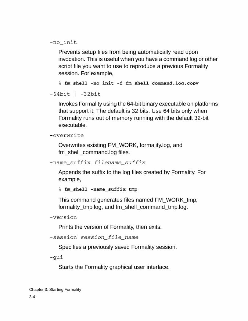
-no_init
Prevents setup files from being automatically read uponinvocation. This is useful when you have a command log or otherscript file you want to use to reproduce a previous Formalitysession. For example,
% fm_shell -no_init -f fm_shell_command.log.copy
-64bit | -32bit
Invokes Formality using the 64-bit binary executable on platformsthat support it. The default is 32 bits. Use 64 bits only whenFormality runs out of memory running with the default 32-bitexecutable.
-overwrite
Overwrites existing FM_WORK, formality.log, andfm_shell_command.log files.
-name_suffix filename_suffix
Appends the suffix to the log files created by Formality. Forexample,
% fm_shell -name_suffix tmp
This command generates files named FM_WORK_tmp,formality_tmp.log, and fm_shell_command_tmp.log.
-version
Prints the version of Formality, then exits.
-session session_file_name
Specifies a previously saved Formality session.
-gui
Starts the Formality graphical user interface.
3-4
Chapter 3: Starting Formality
Invoking the Formality GUI
When you start Formality, you are provided with a transcript windowcontaining the Formality banner. Immediately after the banner isdisplayed, Formality lists two key features for the current release.
To invoke the Formality GUI, at the operating system prompt enterone of the following:
•% fm_shell...fm_shell (setup)>
The fm_shell command starts the Formality shell environmentand command-line interface. From here, start the GUI as follows:
fm_shell (setup)> start_gui
•% fm_shell -gui
If you use the Formality GUI, a pop-up window appears listing all ofthe key features for the current release. You can hide this window forfuture releases. To access these key features at any time, chooseHelp > Release Highlights.
You can choose to display or hide primary sections of the GUIsession window. For example, to hide or display the toolbar or statusbar, use the View menu. In the menu, select an option to display orhide the corresponding area of the session window. A check mark isshown next to the menu item if that section is currently beingdisplayed in the window.
3-5
Invoking Formality
The lower area of the window contains the command console,Formality prompt, and status bar. Use the Log, Errors, Warnings,History, and Last Command options above the Formality prompt todisplay different types of information in the command console.
You can exit the GUI without exiting the Formality session byselecting File > Close GUI.
Formality Shell Environment
This section includes the following topics related to using theFormality fm_shell commands:
• Entering Commands
• Supplying Lists of Arguments
• Editing From the Command Line
• Listing Previously Entered Commands
• Recalling Commands
• Redirecting Output
• Using Command Aliases
• Listing Design Objects
For more information about the Tcl syntax, see Appendix A,“Appendix A - Tcl Syntax as Applied to Formality Shell Commands.”If you want more information about the Tcl language, consult booksabout Tcl in the engineering section of your local bookstore or library.
3-6
Chapter 3: Starting Formality
Entering Commands
Formality considers case when it processes fm_shell commands. Allcommand names, option names, and arguments are case-sensitive.For example, the following two commands are equivalent but refer totwo different containers, named r and R:
fm_shell (setup)> read_verilog -r top.vfm_shell (setup)> read_verilog -R top.v
Each Formality command returns a result that is always a string. Theresult can be passed directly to another command, or it can be usedin a conditional expression. For example, the following commanduses an expression to derive the right side of the resulting equation:
fm_shell (setup)> echo 3+4=[expr 3+4]3+4=7
When you enter a long command with many options and arguments,you can extend the command across more than one line by using thebackslash (\) continuation character. During a continuing commandinput (or in other incomplete input situations), Formality displays asecondary prompt, the question mark (?). Here is an example:
fm_shell (setup)> read_verilog -r “top.v \? bottom.v”Loading verilog file...Current container set to ‘r’1fm_shell (setup)>
3-7
Formality Shell Environment
Supplying Lists of Arguments
When you supply more than one argument for a given Formalitycommand, adhere to Tcl rules. Most publications about Tcl containextensive discussions about specifying lists of arguments withcommands. This section highlights some important concepts.
• Because command arguments and results are represented asstrings, lists are also represented as strings, but with a specificstructure.
• Lists are typically entered by enclosing a string in braces, asfollows:
{file_1 file_2 file_3 file_4}
In the preceding example, however, the string inside the braces isequivalent to the following list:
[list file_1 file_2 file_3 file_4]
Note:Do not use commas to separate list items.
If you are attempting to perform command or variable substitution,the form with braces does not work. For example, the followingcommand reads a single file that contains designs in the Synopsysinternal .db format. The file is located in a directory defined by theDESIGNS variable.
fm_shell (setup)> read_db $DESIGNS/my_file.dbLoading db file '/u/project/designs/my_file.db'No target library specified, default is WORK1fm_shell (setup)>
3-8
Chapter 3: Starting Formality
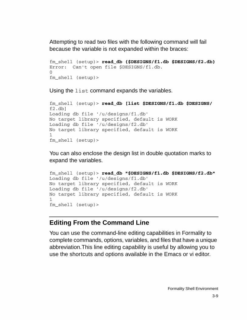
Attempting to read two files with the following command will failbecause the variable is not expanded within the braces:
fm_shell (setup)> read_db {$DESIGNS/f1.db $DESIGNS/f2.db}Error: Can't open file $DESIGNS/f1.db.0fm_shell (setup)>
Using the list command expands the variables.
fm_shell (setup)> read_db [list $DESIGNS/f1.db $DESIGNS/f2.db]Loading db file '/u/designs/f1.db'No target library specified, default is WORKLoading db file '/u/designs/f2.db'No target library specified, default is WORK1fm_shell (setup)>
You can also enclose the design list in double quotation marks toexpand the variables.
fm_shell (setup)> read_db "$DESIGNS/f1.db $DESIGNS/f2.db"Loading db file '/u/designs/f1.db'No target library specified, default is WORKLoading db file '/u/designs/f2.db'No target library specified, default is WORK1fm_shell (setup)>
Editing From the Command Line
You can use the command-line editing capabilities in Formality tocomplete commands, options, variables, and files that have a uniqueabbreviation.This line editing capability is useful by allowing you touse the shortcuts and options available in the Emacs or vi editor.
3-9
Formality Shell Environment
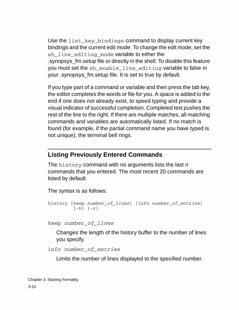
Use the list_key_bindings command to display current keybindings and the current edit mode. To change the edit mode, set thesh_line_editing_mode variable to either the.synopsys_fm.setup file or directly in the shell. To disable this featureyou must set the sh_enable_line_editing variable to false inyour .synopsys_fm.setup file. It is set to true by default.
If you type part of a command or variable and then press the tab key,the editor completes the words or file for you. A space is added to theend if one does not already exist, to speed typing and provide avisual indicator of successful completion. Completed text pushes therest of the line to the right. If there are multiple matches, all matchingcommands and variables are automatically listed. If no match isfound (for example, if the partial command name you have typed isnot unique), the terminal bell rings.
Listing Previously Entered Commands
The history command with no arguments lists the last ncommands that you entered. The most recent 20 commands arelisted by default.
The syntax is as follows:
history [keep number_of_lines] [info number_of_entries][-h] [-r]
keep number_of_lines
Changes the length of the history buffer to the number of linesyou specify.
info number_of_entries
Limits the number of lines displayed to the specified number.
3-10
Chapter 3: Starting Formality
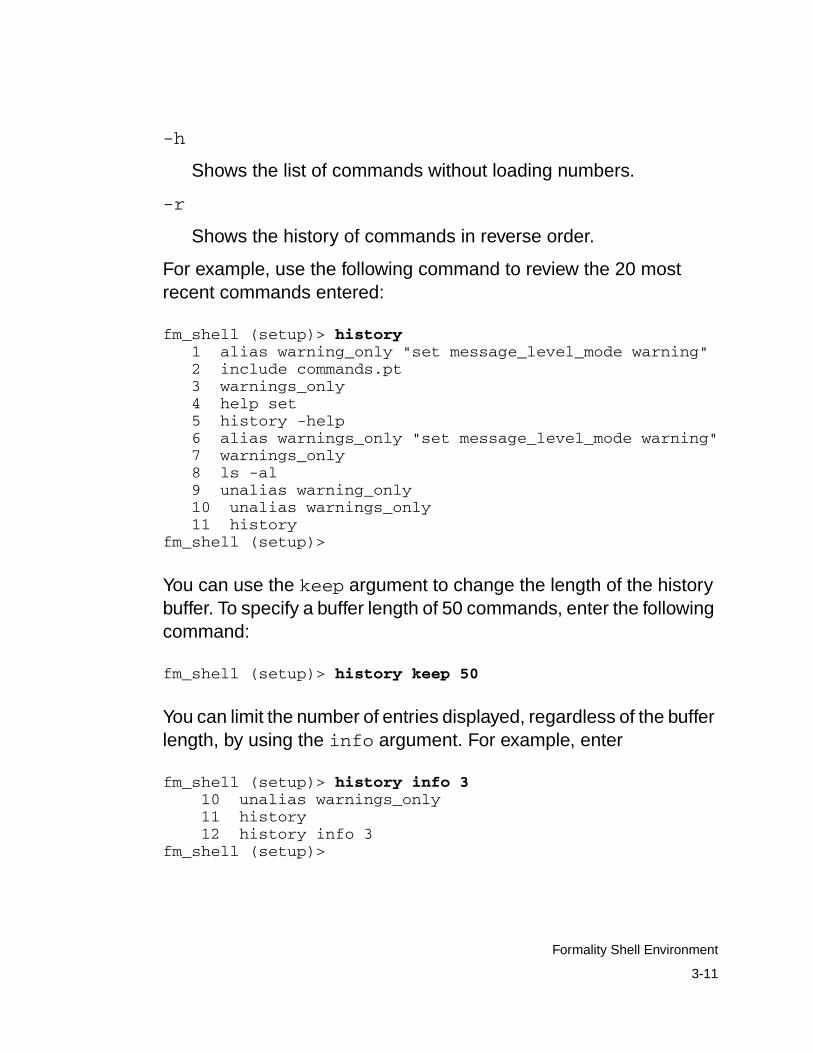
-h
Shows the list of commands without loading numbers.
-r
Shows the history of commands in reverse order.
For example, use the following command to review the 20 mostrecent commands entered:
fm_shell (setup)> history 1 alias warning_only "set message_level_mode warning" 2 include commands.pt 3 warnings_only 4 help set 5 history -help 6 alias warnings_only "set message_level_mode warning" 7 warnings_only 8 ls -al 9 unalias warning_only 10 unalias warnings_only 11 historyfm_shell (setup)>
You can use the keep argument to change the length of the historybuffer. To specify a buffer length of 50 commands, enter the followingcommand:
fm_shell (setup)> history keep 50
You can limit the number of entries displayed, regardless of the bufferlength, by using the info argument. For example, enter
fm_shell (setup)> history info 3 10 unalias warnings_only 11 history 12 history info 3fm_shell (setup)>
3-11
Formality Shell Environment
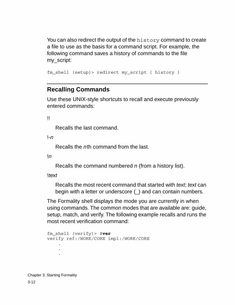
You can also redirect the output of the history command to createa file to use as the basis for a command script. For example, thefollowing command saves a history of commands to the filemy_script:
fm_shell (setup)> redirect my_script { history }
Recalling Commands
Use these UNIX-style shortcuts to recall and execute previouslyentered commands:
!!
Recalls the last command.
!-n
Recalls the nth command from the last.
!n
Recalls the command numbered n (from a history list).
!text
Recalls the most recent command that started with text; text canbegin with a letter or underscore (_) and can contain numbers.
The Formality shell displays the mode you are currently in whenusing commands. The common modes that are available are: guide,setup, match, and verify. The following example recalls and runs themost recent verification command:
fm_shell (verify)> !ververify ref:/WORK/CORE impl:/WORK/CORE
.
.
.
3-12
Chapter 3: Starting Formality
fm_shell (verify)>
This example recalls and starts the most recently run command:
fm_shell (setup)> !! 1 unalias warnings_only 2 read_verilog -r top.vfm_shell (setup)>
Redirecting Output
You can cause Formality to redirect the output of a command or ascript to a specified file by using the Tcl redirect command orusing the > and >> operators.
Use the redirect command in the following form to redirect outputto a file:
fm_shell(setup)> redirect file_name "command_string"
For more information about the redirect command, see the manpage.
Use a command in the following form to redirect output to a file byusing the > operator:
fm_shell(setup)> command > file
If the file does not exist, Formality creates it. If the file does exist,Formality overwrites it with new output.
Use a command in the following form to append output to a file:
fm_shell (setup)> command >> file
3-13
Formality Shell Environment
If the file does not exist, Formality creates it. If the file does exist,Formality adds the output to the end of the file.
Unlike UNIX, Formality treats the > and >> operators as argumentsto a command. Consequently, you must use spaces to separate theoperator from the command and from the target file. In the followingexample, the first line is incorrect:
fm_shell (setup)> echo $my_variable>>file.outfm_shell (setup)> echo $my_variable >> file.out
Note:The Tcl built-in command puts does not redirect output.Formality provides a similar command, echo, that allows outputredirection.
Using Command Aliases
You can use aliases to create short forms for the commands youcommonly use. For example, the following command creates analias called err_only that invokes the set command:
fm_shell (setup)> alias err_only "set message_level_modeerror”
After creating the alias, you can use it by entering err_only at thefm_shell prompt.
The following points apply to alias behavior and use:
• Aliases are recognized only when they are the first word of acommand.
• Alias definitions take effect immediately and last only while theFormality session is active.
3-14
Chapter 3: Starting Formality
• Formality reads the .synopsys_fm.setup file when you invoke it;therefore, define commonly used aliases in the setup file.
• You cannot use an existing command name as an alias name.However, aliases can refer to other aliases.
• You can supply arguments when defining an alias by surroundingthe entire definition for the alias in quotation marks.
Using the alias Command
The syntax of the alias command is as follows:
alias [name [definition ] ]
name
Represents the name (short form) of the alias you are creating (ifa definition is supplied) or listing (if no definition is supplied). Thename can contain letters, digits, and the underscore character(_). If no name is given, all aliases are listed.
definition
Represents the command and list of options for which you arecreating an alias. If an alias is already specified, definitionoverwrites the existing definition. If no definition is specified, thedefinition of the named alias is displayed.
When you create an alias for a command containing dash options,enclose the whole command in quotation marks.
Using the unalias Command
The unalias command removes alias definitions. The syntax of theunalias command is as follows:
3-15
Formality Shell Environment
unalias [pattern... ]
pattern
Lists one or more patterns that match existing aliases whosedefinitions you want removed.
For example, use the following command to remove theset_identity_check alias:
fm_shell (setup)> unalias set_identity_check
Listing Design Objects
At the fm_shell prompt, you can create lists of pins, ports, cells, nets,and references by using a variety of fm_shell commands that beginwith find_ (such as find_cells and find_nets). Here aresome examples using the find_ commands.
The following command lists all the input ports that start with SCAN:
find_ports -input container:/library/design/SCAN*
The following command returns a list of all pins (across hierarchy)that are connected to net123 in the specified design:
find_pins -hierarchy -of_object container:/library/design/net123
The following command returns the name of the design that isreferenced by cell123:
find_references -of_object container:/library/design/cell123
For more information about these commands, see the man pages.
3-16
Chapter 3: Starting Formality
Using the Formality GUI Environment
This section includes the following topics that relate to using theFormality GUI:
• Managing Formality Windows
• Using the Formality Prompt
• Saving the Transcript
• Copying Text From the Transcript Area
• Copying Text to the Formality Prompt
Managing Formality Windows
The Formality GUI uses multiple windows to display different typesof information, such as schematics and logic cones. These windowsare opened by certain menu commands in the GUI.
The Window menu lists the GUI windows that are present and letsyou manage those windows. It lists up to nine Formality windows.Selecting any window in the list “activates” that window (restores thewindow from icon form, if necessary, and moves it to the front).
For more information about the various windows available to you,see the following sections:
• “Working With Schematics” on page 7-29
• “Working With Logic Cones” on page 7-38
• “Working With Failing Patterns” on page 7-44
3-17
Using the Formality GUI Environment
Using the Formality Prompt
The Formality prompt allows you to run fm_shell commands withoutleaving the GUI.
To run an fm_shell command from within the GUI, follow thesesteps:
1. Enter the desired command in the text area at the Formalityprompt. You can use any of these methods:
- Type the command directly.
- Click History, then copy and paste commands into the text box.
2. Press the Enter key to execute the command.
After you perform these steps, Formality runs the command andadds it to the command history list. The transcript area displays thecommand results.
You can use multiple lines at the prompt by pressing Shift-Enter tomove to the next line. Specify a “\” at the end of each line to indicatethat the text continues on the next line.
Press the Shift-Up Arrow or Shift-Down Arrow key to cycle throughthe command history.
Saving the Transcript
To save the transcript area, follow these steps:
1. Choose File > Save Transcript to open the Save Transcript Filedialog box.
3-18
Chapter 3: Starting Formality
2. Enter a file name or use the browser to select the file in which tosave the transcript text.
3. Click Save.
Copying Text From the Transcript Area
You can copy text to another application window by following thesesteps:
1. To display the transcript, click Log.
2. Select the text in the transcript area you want to copy.
3. Right-click and choose Copy.
4. Move the pointer to a shell window outside the Formality tool, orto another open application, and execute the Paste command.
In addition, you can use the UNIX-style method of selecting with theleft-mouse button and pasting with the middle-mouse button totransfer text into a shell window.
Copying Text to the Formality Prompt
You can copy text from an application window to the Formalityprompt by following these steps:
1. Select the text you want to copy.
2. Use the Copy command to place the highlighted text on theclipboard.
3. Locate the pointer in the command bar where you want the textto appear, and execute the Paste command.
3-19
Using the Formality GUI Environment
In addition, you can use the UNIX-style method of selecting with theleft-mouse button and pasting with the middle-mouse button totransfer text from a shell window to the prompt line.
General Formality Usage Options
Whether you work in fm_shell or the GUI, Formality provides certainfacilities that can increase your productivity and the tool’s overallease of use. The following sections describe these facilities:
• Getting Help
• Interrupting Formality
• Controlling Messages
• Working With Script Files
• Using the Command Log File
• Controlling the File Search Path
Getting Help
Formality provides various forms of online help, such as the helpand man commands.
You can use a wildcard pattern as the argument for the helpcommand. The available wildcards are
*
Matches any number of characters.
3-20
Chapter 3: Starting Formality
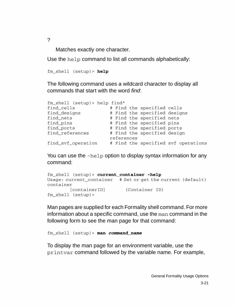
?
Matches exactly one character.
Use the help command to list all commands alphabetically:
fm_shell (setup)> help
The following command uses a wildcard character to display allcommands that start with the word find:
fm_shell (setup)> help find*find_cells # Find the specified cellsfind_designs # Find the specified designsfind_nets # Find the specified netsfind_pins # Find the specified pinsfind_ports # Find the specified portsfind_references # Find the specified design
referencesfind_svf_operation # Find the specified svf operations
You can use the -help option to display syntax information for anycommand:
fm_shell (setup)> current_container -helpUsage: current_container # Set or get the current (default)container [containerID] (Container ID)fm_shell (setup)>
Man pages are supplied for each Formality shell command. For moreinformation about a specific command, use the man command in thefollowing form to see the man page for that command:
fm_shell (setup)> man command_name
To display the man page for an environment variable, use theprintvar command followed by the variable name. For example,
3-21
General Formality Usage Options
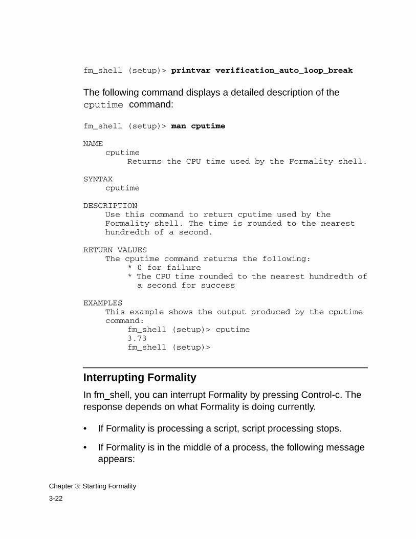
fm_shell (setup)> printvar verification_auto_loop_break
The following command displays a detailed description of thecputime command:
fm_shell (setup)> man cputime
NAMEcputime
Returns the CPU time used by the Formality shell.
SYNTAXcputime
DESCRIPTIONUse this command to return cputime used by theFormality shell. The time is rounded to the nearesthundredth of a second.
RETURN VALUESThe cputime command returns the following:
* 0 for failure* The CPU time rounded to the nearest hundredth of a second for success
EXAMPLESThis example shows the output produced by the cputimecommand:
fm_shell (setup)> cputime3.73fm_shell (setup)>
Interrupting Formality
In fm_shell, you can interrupt Formality by pressing Control-c. Theresponse depends on what Formality is doing currently.
• If Formality is processing a script, script processing stops.
• If Formality is in the middle of a process, the following messageappears:
3-22
Chapter 3: Starting Formality
Interrupt detected: Stopping current operation
Depending on the design, it can take Formality one or twominutes to respond to Control-c.
• If Formality is waiting for a command (not in the middle of aprocess), the following message appears:
Interrupt detected: Application exits after three ^Cinterrupts
In this case, you can exit Formality and return to the UNIX shellby pressing Control-c two more times within 20 seconds, with nomore than 10 seconds between each press.
In the GUI, when you run a verification, a progress bar appears in thestatus bar. You can interrupt the process by clicking Stop. Processingmight not stop immediately.
Controlling Messages
Formality issues messages in certain formats and during certainsituations. You can control the types of messages Formality displays.
Formality generates messages in one of two formats:
severity: message (code)severity: message
severity
Represents the level of severity (note, warning, or error) asdescribed in Table 3-1.
message
The text of the message.
3-23
General Formality Usage Options
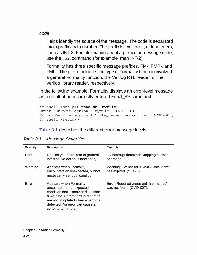
code
Helps identify the source of the message. The code is separatedinto a prefix and a number. The prefix is two, three, or four letters,such as INT-2. For information about a particular message code,use the man command (for example, man INT-2).
Formality has three specific message prefixes, FM-, FMR-, andFML-. The prefix indicates the type of Formality function involved:a general Formality function, the Verilog RTL reader, or theVerilog library reader, respectively.
In the following example, Formality displays an error-level messageas a result of an incorrectly entered read_db command:
fm_shell (setup)> read_db -myfileError: unknown option '-myfile' (CMD-010)Error: Required argument 'file_names' was not found (CMD-007)fm_shell (setup)>
Table 3-1 describes the different error message levels.
Table 3-1 Message Severities
Severity Description Example
Note Notifies you of an item of generalinterest. No action is necessary.
^C Interrupt detected: Stopping currentoperation
Warning Appears when Formalityencounters an unexpected, but notnecessarily serious, condition.
Warning: License for “DW-IP-Consultant”has expired. (SEC-6)
Error Appears when Formalityencounters an unexpectedcondition that is more serious thana warning. Commands in progressare not completed when an error isdetected. An error can cause ascript to terminate.
Error: Required argument “file_names”was not found (CMD-007).
3-24
Chapter 3: Starting Formality
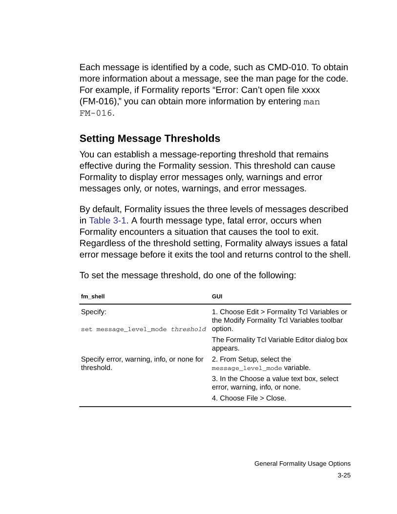
Each message is identified by a code, such as CMD-010. To obtainmore information about a message, see the man page for the code.For example, if Formality reports “Error: Can’t open file xxxx(FM-016),” you can obtain more information by entering manFM-016.
Setting Message Thresholds
You can establish a message-reporting threshold that remainseffective during the Formality session. This threshold can causeFormality to display error messages only, warnings and errormessages only, or notes, warnings, and error messages.
By default, Formality issues the three levels of messages describedin Table 3-1. A fourth message type, fatal error, occurs whenFormality encounters a situation that causes the tool to exit.Regardless of the threshold setting, Formality always issues a fatalerror message before it exits the tool and returns control to the shell.
To set the message threshold, do one of the following:
fm_shell GUI
Specify:
set message_level_mode threshold
Specify error, warning, info, or none forthreshold.
1. Choose Edit > Formality Tcl Variables orthe Modify Formality Tcl Variables toolbaroption.
The Formality Tcl Variable Editor dialog boxappears.
2. From Setup, select themessage_level_mode variable.
3. In the Choose a value text box, selecterror, warning, info, or none.
4. Choose File > Close.
3-25
General Formality Usage Options
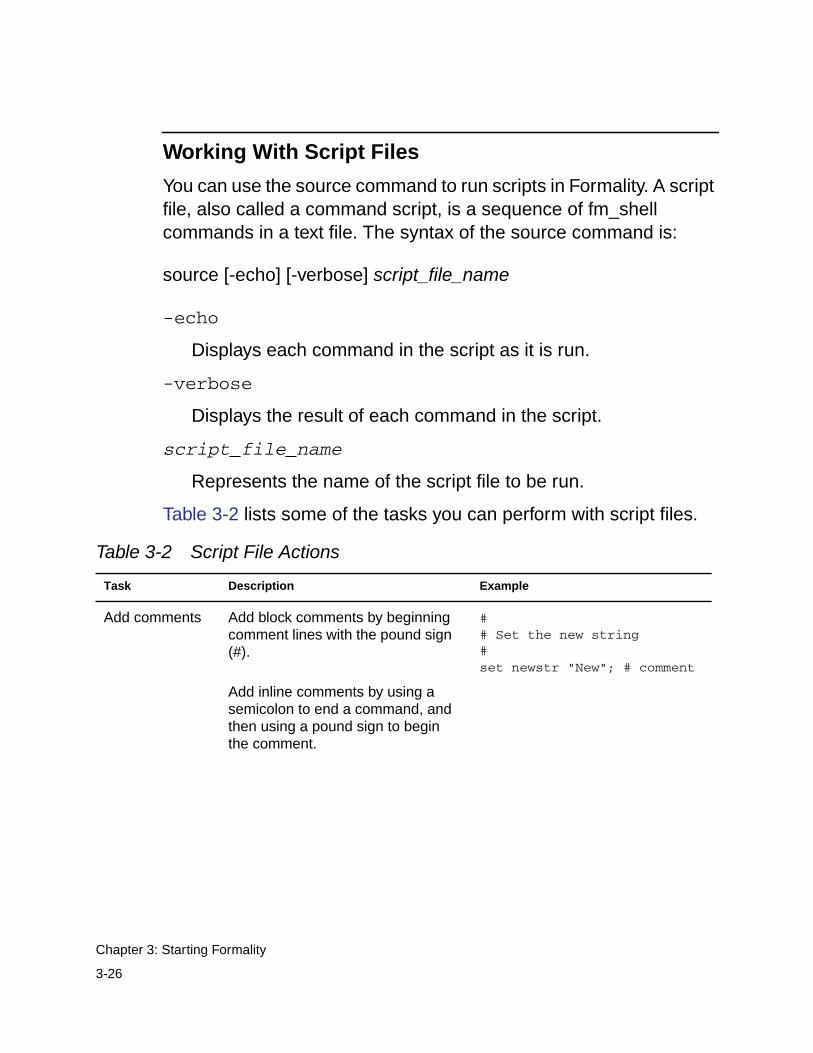
Working With Script Files
You can use the source command to run scripts in Formality. A scriptfile, also called a command script, is a sequence of fm_shellcommands in a text file. The syntax of the source command is:
source [-echo] [-verbose] script_file_name
-echo
Displays each command in the script as it is run.
-verbose
Displays the result of each command in the script.
script_file_name
Represents the name of the script file to be run.
Table 3-2 lists some of the tasks you can perform with script files.
Table 3-2 Script File Actions
Task Description Example
Add comments Add block comments by beginningcomment lines with the pound sign(#).
Add inline comments by using asemicolon to end a command, andthen using a pound sign to beginthe comment.
## Set the new string#set newstr "New"; # comment
3-26
Chapter 3: Starting Formality
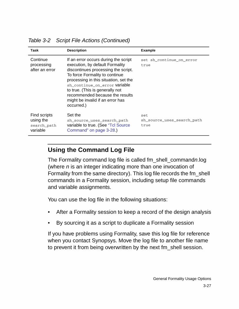
Using the Command Log File
The Formality command log file is called fm_shell_commandn.log(where n is an integer indicating more than one invocation ofFormality from the same directory). This log file records the fm_shellcommands in a Formality session, including setup file commandsand variable assignments.
You can use the log file in the following situations:
• After a Formality session to keep a record of the design analysis
• By sourcing it as a script to duplicate a Formality session
If you have problems using Formality, save this log file for referencewhen you contact Synopsys. Move the log file to another file nameto prevent it from being overwritten by the next fm_shell session.
Continueprocessingafter an error
If an error occurs during the scriptexecution, by default Formalitydiscontinues processing the script.To force Formality to continueprocessing in this situation, set thesh_continue_on_error variableto true. (This is generally notrecommended because the resultsmight be invalid if an error hasoccurred.)
set sh_continue_on_errortrue
Find scriptsusing thesearch_pathvariable
Set thesh_source_uses_search_pathvariable to true. (See “Tcl SourceCommand” on page 3-28.)
setsh_source_uses_search_pathtrue
Table 3-2 Script File Actions (Continued)
Task Description Example
3-27
General Formality Usage Options
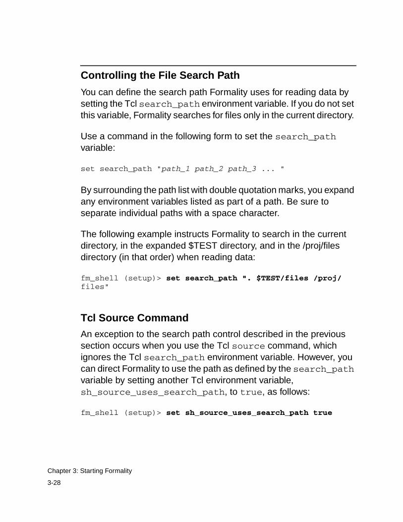
Controlling the File Search Path
You can define the search path Formality uses for reading data bysetting the Tcl search_path environment variable. If you do not setthis variable, Formality searches for files only in the current directory.
Use a command in the following form to set the search_pathvariable:
set search_path "path_1 path_2 path_3 ... "
By surrounding the path list with double quotation marks, you expandany environment variables listed as part of a path. Be sure toseparate individual paths with a space character.
The following example instructs Formality to search in the currentdirectory, in the expanded $TEST directory, and in the /proj/filesdirectory (in that order) when reading data:
fm_shell (setup)> set search_path ". $TEST/files /proj/files"
Tcl Source Command
An exception to the search path control described in the previoussection occurs when you use the Tcl source command, whichignores the Tcl search_path environment variable. However, youcan direct Formality to use the path as defined by the search_pathvariable by setting another Tcl environment variable,sh_source_uses_search_path, to true, as follows:
fm_shell (setup)> set sh_source_uses_search_path true
3-28
Chapter 3: Starting Formality

Examining the File Search Path
You can examine the current file search path that Formality is usingby entering the following command:
fm_shell (setup)> echo $search_path
3-29
General Formality Usage Options

3-30
Chapter 3: Starting Formality
4Setting Basic Elements for DesignVerification 4
Prior to design verification you must have a few basic elements inplace, such as your libraries and designs. This chapter describes theread-design flow where you specify the libraries, designs, andtop-level cells.
This chapter includes the following sections:
• Reading in Libraries and Designs
• Loading the Reference Design
• Loading the Implementation Design
• Setting Up and Managing Containers
This chapter’s subject matter pertains to the boxes outlined inFigure 4-1.
4-1
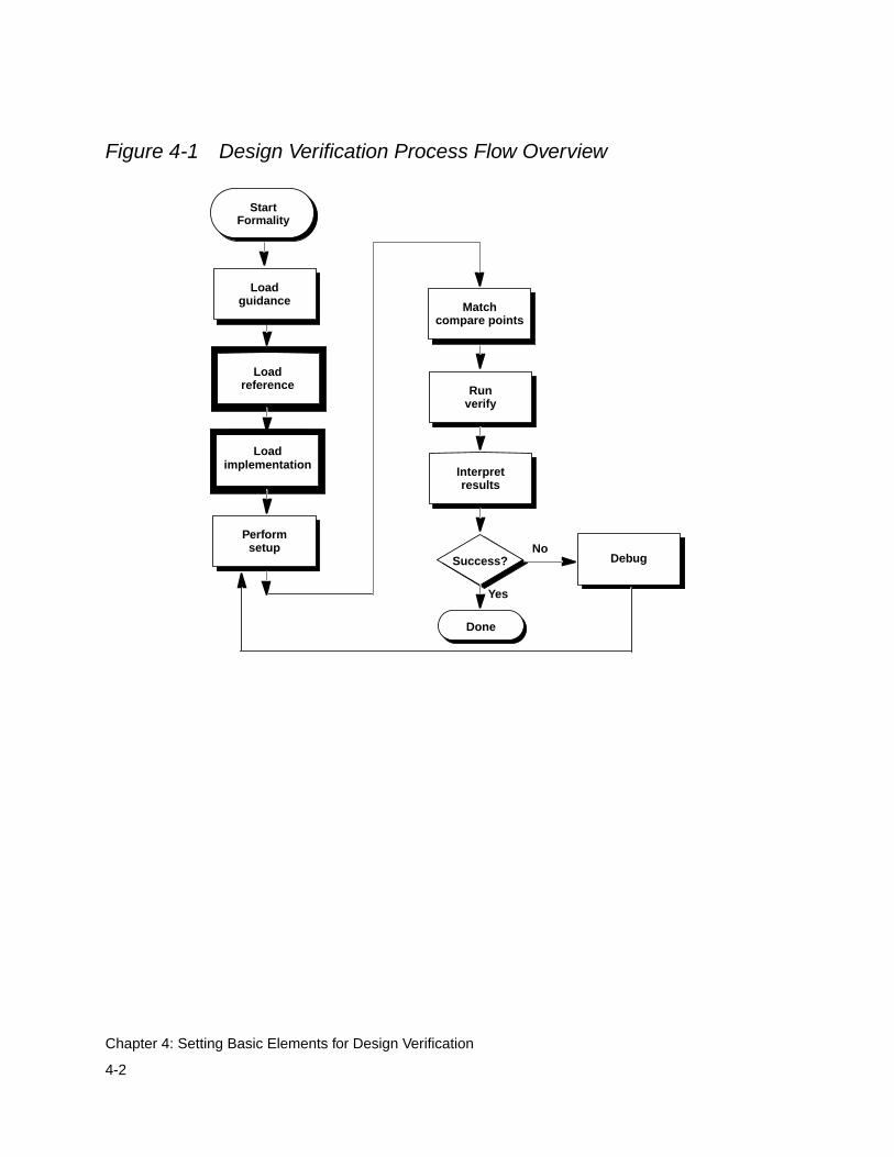
Figure 4-1 Design Verification Process Flow Overview
Loadreference
Load
Interpretresults
Performsetup
Runverify
Success?No
Yes
Done
Matchcompare points
implementation
Debug
StartFormality
Loadguidance
4-2
Chapter 4: Setting Basic Elements for Design Verification
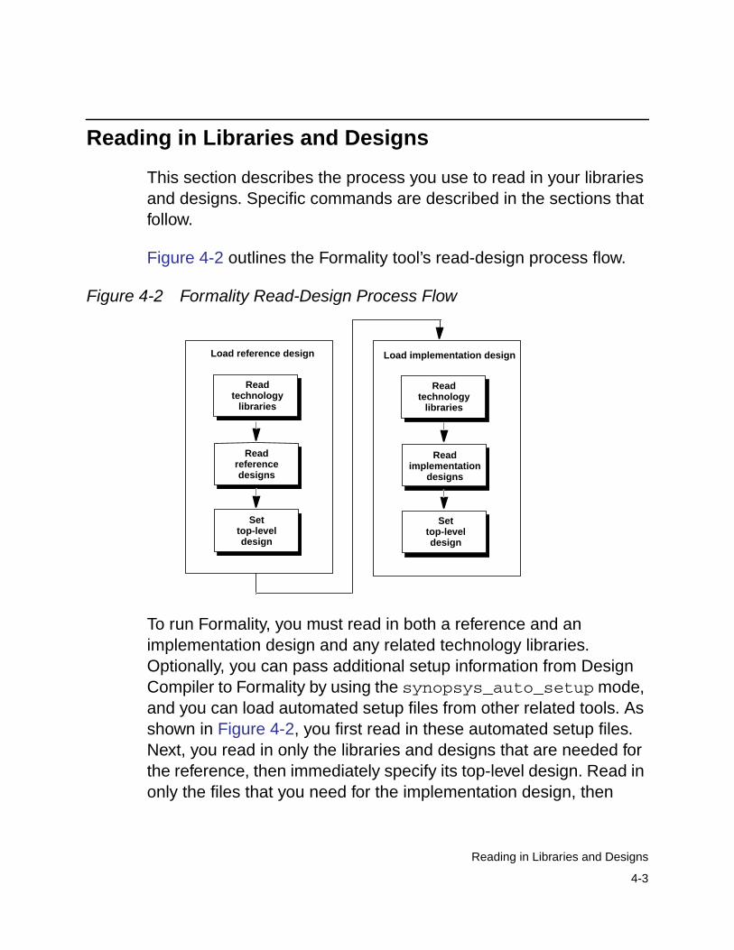
Reading in Libraries and Designs
This section describes the process you use to read in your librariesand designs. Specific commands are described in the sections thatfollow.
Figure 4-2 outlines the Formality tool’s read-design process flow.
Figure 4-2 Formality Read-Design Process Flow
To run Formality, you must read in both a reference and animplementation design and any related technology libraries.Optionally, you can pass additional setup information from DesignCompiler to Formality by using the synopsys_auto_setup mode,and you can load automated setup files from other related tools. Asshown in Figure 4-2, you first read in these automated setup files.Next, you read in only the libraries and designs that are needed forthe reference, then immediately specify its top-level design. Read inonly the files that you need for the implementation design, then
Read
Load reference design Load implementation design
technologylibraries
Readtechnology
libraries
Readreferencedesigns
Readimplementation
designs
Settop-leveldesign
Settop-leveldesign
4-3
Reading in Libraries and Designs
immediately specify its top-level design. Finally, you must set thetop-level design for the reference design before proceeding to theimplementation design.
To use synopsys_auto_setup_mode, thesynopsys_auto_setup variable must be set to true before theset_svf command is used. If synopsys_auto_setup_mode isset to true, the following Formality variables will be set as follows:
hdlin_ignore_parallel_case = false
hdlin_ignore_full_case = false
verification_set_undriven_signals = 0:X
hdlin_error_on_mismatch_message = false
svf_ignore_unqualified_fsm_information = false (onlychanged when there are guide_fsm_reencoding commands inthe automated setup file)
You can override any individual variable setting of thesynopsys_auto_setup mode by manually setting any of theabove variables after the synopsys_auto_setup_mode variablehas been set.
If synopsys_auto_setup is set to true and the set_svfcommand was used to read in a automated setup file, then additionalsetup information (external constraints) will be passed to Formalitythrough the automated setup file. Design Compiler began generatingthis additional information in the automated setup file starting withthe 2007.03 release.
4-4
Chapter 4: Setting Basic Elements for Design Verification
A summary report will be generated and included in the Formalitytranscript that lists all non-default variable settings and externalconstraint information passed via the automated setup file.
Setup-free Flow
Automated setup information is provided by Design Compiler,including clock gating and scan insertion, and this is recognized byFormality.
Formality recognizes the following commands if they appear in theautomated setup file when the synopsys_auto_setup variable isset to true before the set_svf command is issued:
guide_environment
guide_scan_input
guide_port_constant
If the verification_verify_directly_undriven_outputvariable is set to true, Formality will issue theset_dont_verify –directly_undriven_output commandat the beginning of the match phase. This prevents undriven outputs(typically scan outputs) in the reference design from causing a failingverification. The default value for this variable is false.
If clock gating is inserted by Design Compiler or Power Compiler, aguide_environment command is issued by Design Compiler tothe automated setup file. Formality will set the value of theverification_clock_gate_hold_mode variable to the anyvalue.
4-5
Reading in Libraries and Designs
Formality will use the following variable values in theguide_environment command in the automated setup file:
bus_dimension_separator_style
bus_extraction_style
bus_naming_style
bus_range_separator_style
hdl_naming_threshold
hdlin_array_instance_naming_style
hdlin_cell_naming_style
hdlin_generate_naming_style
hdlin_generate_separator_style
hdlin_sv_packages
hdlin_while_loop_iterations
template_naming_style
template_parameter_style
template_separator_style
hdlin_dyn_array_bnd_check (only if synopsys_auto_setupis set to true)
4-6
Chapter 4: Setting Basic Elements for Design Verification
Any of the variable values changed by the synopsys_auto_setupvariable can be changed by the user after the set_svf command iscompleted and will retain the user-defined values.
Designs compiled using Design Compiler Z-2007.03 will contain theautomated setup file commands mentioned above. To ensure setupis complete, synopsys_auto_setup set to true before issuingthe set_svf command.
A summary report will be generated and included in the Formalitytranscript listing all non-default variable settings and externalconstraint information passed via the automated setup file.
Technology Libraries
For proper design verification, you generally need to read intechnology libraries that contain descriptions of the lowest-level, orprimitive, cells used in the design. Cell libraries is an alternative termfor technology libraries. To learn how to verify two technologylibraries, see Chapter 8, “Technology Library Verification.”
Formality often needs primitive-cell information to determine thebehavior of each cell so that it can perform a gate-level comparisonbetween the reference and implementation designs.
Formality can read the following types of technology libraries:
• Synopsys internal database (.db) files
• Synthesizable Verilog RTL files
• Synthesizable VHDL RTL files
• Verilog simulation library files
4-7
Reading in Libraries and Designs
Formality reads one or more cell description files in the specifiedformat and puts the cell definition information into a technologylibrary. Formality uses this information when it performs acomparison between different designs.
For a purely RTL design description, reading a technology library isnot necessary.
Designs
Designs are collections of design objects. A design library providesthe same functionality as a technology library except that the detailsof a design library are visible to the user. Use a design library whenyou want the data to be restricted to a single design, such as RTL orgate-level netlists.
You can read designs into the Formality environment in the followingformats:
Milkyway database
Files in binary format that specify the designs for a Milkywaydatabase. Milkyway only supports designs that are fully mappedand unique. The hierarchical netlist data is read in; however,synthetic constraints and physical data, such as floor plan data,are not read in.
Synopsys internal database (.db or .ddc) designs
Files compiled by Design Compiler or files that representtechnology libraries. Reading a Synopsys internal database fileinto a container results in a design library that can consist of oneor more designs.
4-8
Chapter 4: Setting Basic Elements for Design Verification
SystemVerilog files
Files consisting of SystemVerilog modules that, when read into acontainer, represent a design library that can consist of one ormore designs.
Verilog files
Files consisting of Verilog modules that, when read into acontainer, represent a design library that can consist of one ormore designs.
VHDL files
Files consisting of VHDL entity and architecture pairs that, whenread into a container, represent a design library that can consistof one or more designs.
The following sections describe environment variables you mightneed to set prior to reading in your designs.
Changing Bus Naming and Dimension Separator Styles
When you read Verilog or VHDL designs into the Formalityenvironment, Formality uses a default bus naming style and a defaultbus dimension separator to support bus names. Formality uses%s[%d] as the bus naming style and a pair of square-bracketcharacters ( ] [ ) as the bus dimension separator.
For example,
BUSA[1]BUSA[2]BUSB[1][1]BUSC[1][2]
4-9
Reading in Libraries and Designs
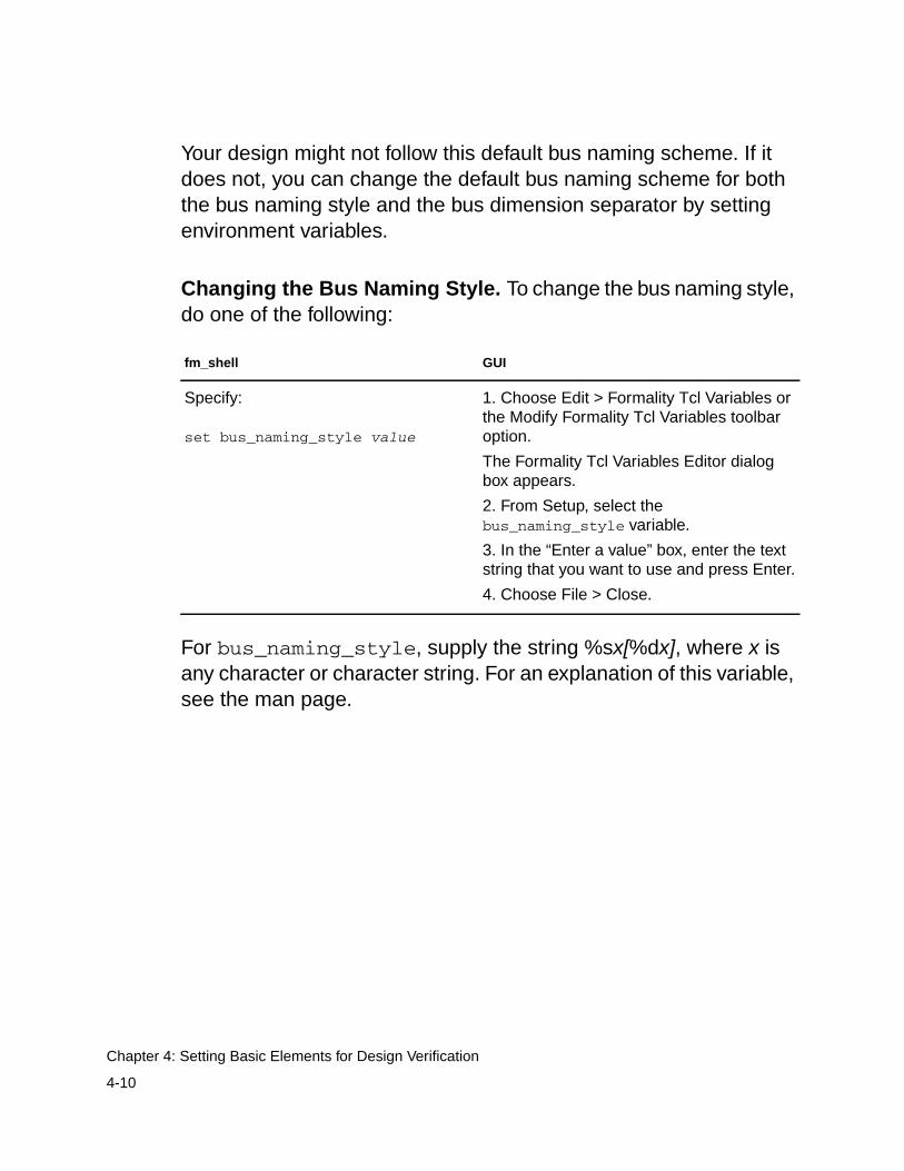
Your design might not follow this default bus naming scheme. If itdoes not, you can change the default bus naming scheme for boththe bus naming style and the bus dimension separator by settingenvironment variables.
Changing the Bus Naming Style. To change the bus naming style,do one of the following:
For bus_naming_style, supply the string %sx[%dx], where x isany character or character string. For an explanation of this variable,see the man page.
fm_shell GUI
Specify:
set bus_naming_style value
1. Choose Edit > Formality Tcl Variables orthe Modify Formality Tcl Variables toolbaroption.
The Formality Tcl Variables Editor dialogbox appears.
2. From Setup, select thebus_naming_style variable.
3. In the “Enter a value” box, enter the textstring that you want to use and press Enter.
4. Choose File > Close.
4-10
Chapter 4: Setting Basic Elements for Design Verification
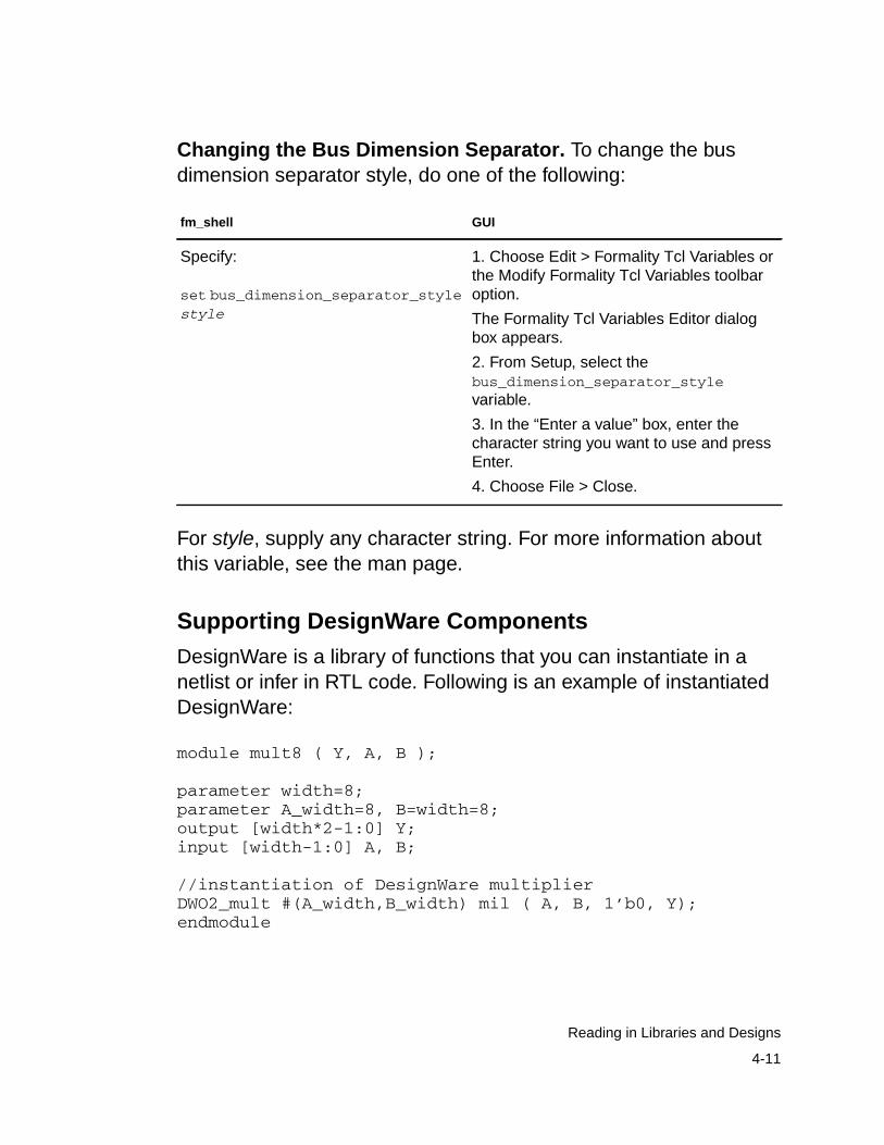
Changing the Bus Dimension Separator. To change the busdimension separator style, do one of the following:
For style, supply any character string. For more information aboutthis variable, see the man page.
Supporting DesignWare Components
DesignWare is a library of functions that you can instantiate in anetlist or infer in RTL code. Following is an example of instantiatedDesignWare:
module mult8 ( Y, A, B );
parameter width=8;parameter A_width=8, B=width=8;output [width*2-1:0] Y;input [width-1:0] A, B;
//instantiation of DesignWare multiplierDWO2_mult #(A_width,B_width) mil ( A, B, 1’b0, Y);endmodule
fm_shell GUI
Specify:
set bus_dimension_separator_stylestyle
1. Choose Edit > Formality Tcl Variables orthe Modify Formality Tcl Variables toolbaroption.
The Formality Tcl Variables Editor dialogbox appears.
2. From Setup, select thebus_dimension_separator_stylevariable.
3. In the “Enter a value” box, enter thecharacter string you want to use and pressEnter.
4. Choose File > Close.
4-11
Reading in Libraries and Designs
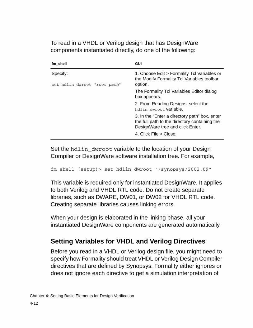
To read in a VHDL or Verilog design that has DesignWarecomponents instantiated directly, do one of the following:
Set the hdlin_dwroot variable to the location of your DesignCompiler or DesignWare software installation tree. For example,
fm_shell (setup)> set hdlin_dwroot "/synopsys/2002.09"
This variable is required only for instantiated DesignWare. It appliesto both Verilog and VHDL RTL code. Do not create separatelibraries, such as DWARE, DW01, or DW02 for VHDL RTL code.Creating separate libraries causes linking errors.
When your design is elaborated in the linking phase, all yourinstantiated DesignWare components are generated automatically.
Setting Variables for VHDL and Verilog Directives
Before you read in a VHDL or Verilog design file, you might need tospecify how Formality should treat VHDL or Verilog Design Compilerdirectives that are defined by Synopsys. Formality either ignores ordoes not ignore each directive to get a simulation interpretation of
fm_shell GUI
Specify:
set hdlin_dwroot "root_path"
1. Choose Edit > Formality Tcl Variables orthe Modify Formality Tcl Variables toolbaroption.
The Formality Tcl Variables Editor dialogbox appears.
2. From Reading Designs, select thehdlin_dwroot variable.
3. In the “Enter a directory path” box, enterthe full path to the directory containing theDesignWare tree and click Enter.
4. Click File > Close.
4-12
Chapter 4: Setting Basic Elements for Design Verification
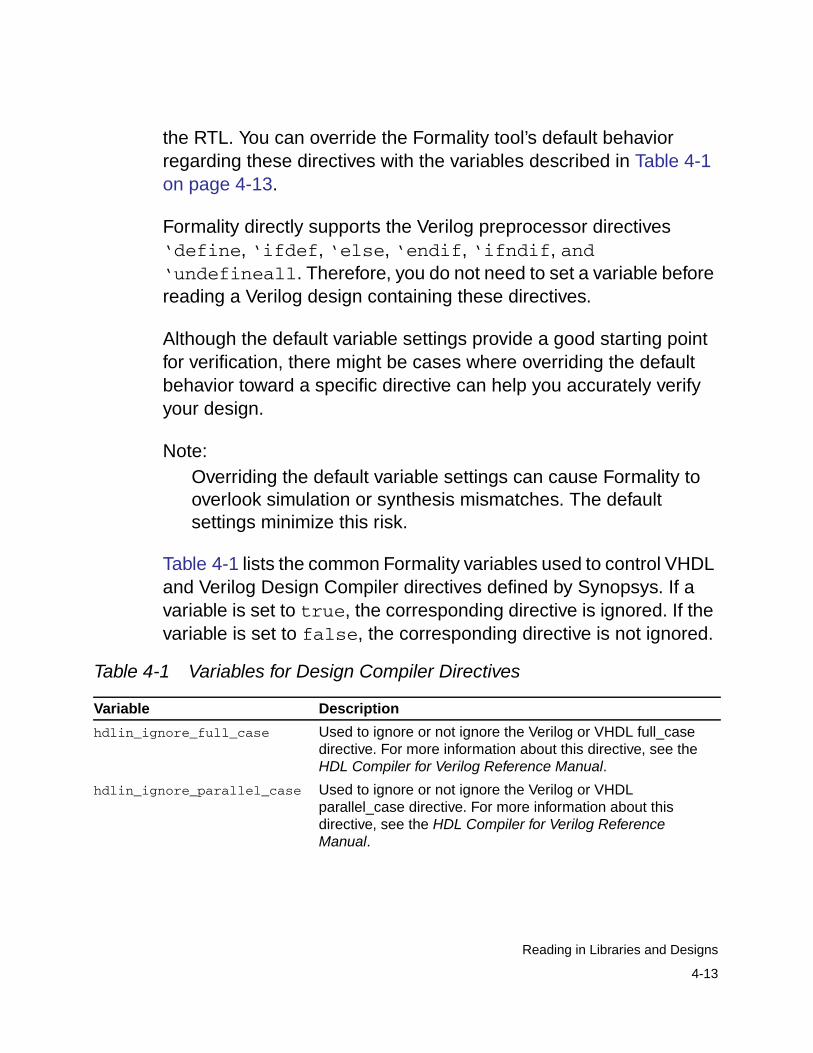
the RTL. You can override the Formality tool’s default behaviorregarding these directives with the variables described in Table 4-1on page 4-13.
Formality directly supports the Verilog preprocessor directives‘define, ‘ifdef, ‘else, ‘endif, ‘ifndif, and‘undefineall. Therefore, you do not need to set a variable beforereading a Verilog design containing these directives.
Although the default variable settings provide a good starting pointfor verification, there might be cases where overriding the defaultbehavior toward a specific directive can help you accurately verifyyour design.
Note:Overriding the default variable settings can cause Formality tooverlook simulation or synthesis mismatches. The defaultsettings minimize this risk.
Table 4-1 lists the common Formality variables used to control VHDLand Verilog Design Compiler directives defined by Synopsys. If avariable is set to true, the corresponding directive is ignored. If thevariable is set to false, the corresponding directive is not ignored.
Table 4-1 Variables for Design Compiler Directives
Variable Description
hdlin_ignore_full_case Used to ignore or not ignore the Verilog or VHDL full_casedirective. For more information about this directive, see theHDL Compiler for Verilog Reference Manual.
hdlin_ignore_parallel_case Used to ignore or not ignore the Verilog or VHDLparallel_case directive. For more information about thisdirective, see the HDL Compiler for Verilog ReferenceManual.
4-13
Reading in Libraries and Designs
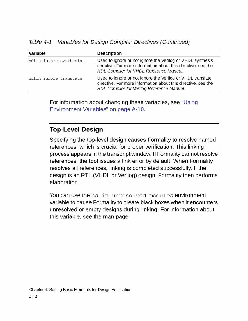
For information about changing these variables, see “UsingEnvironment Variables” on page A-10.
Top-Level Design
Specifying the top-level design causes Formality to resolve namedreferences, which is crucial for proper verification. This linkingprocess appears in the transcript window. If Formality cannot resolvereferences, the tool issues a link error by default. When Formalityresolves all references, linking is completed successfully. If thedesign is an RTL (VHDL or Verilog) design, Formality then performselaboration.
You can use the hdlin_unresolved_modules environmentvariable to cause Formality to create black boxes when it encountersunresolved or empty designs during linking. For information aboutthis variable, see the man page.
hdlin_ignore_synthesis Used to ignore or not ignore the Verilog or VHDL synthesisdirective. For more information about this directive, see theHDL Compiler for VHDL Reference Manual.
hdlin_ignore_translate Used to ignore or not ignore the Verilog or VHDL translatedirective. For more information about this directive, see theHDL Compiler for Verilog Reference Manual.
Table 4-1 Variables for Design Compiler Directives (Continued)
Variable Description
4-14
Chapter 4: Setting Basic Elements for Design Verification
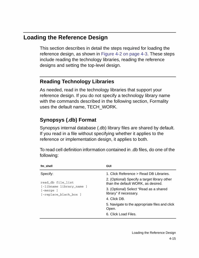
Loading the Reference Design
This section describes in detail the steps required for loading thereference design, as shown in Figure 4-2 on page 4-3. These stepsinclude reading the technology libraries, reading the referencedesigns and setting the top-level design.
Reading Technology Libraries
As needed, read in the technology libraries that support yourreference design. If you do not specify a technology library namewith the commands described in the following section, Formalityuses the default name, TECH_WORK.
Synopsys (.db) Format
Synopsys internal database (.db) library files are shared by default.If you read in a file without specifying whether it applies to thereference or implementation design, it applies to both.
To read cell definition information contained in .db files, do one of thefollowing:
fm_shell GUI
Specify:
read_db file_list[-libname library_name ][-merge ][-replace_black_box ]
1. Click Reference > Read DB Libraries.
2. (Optional) Specify a target library otherthan the default WORK, as desired.
3. (Optional) Select “Read as a sharedlibrary” if necessary.
4. Click DB.
5. Navigate to the appropriate files and clickOpen.
6. Click Load Files.
4-15
Loading the Reference Design
You use the read_db command to read both designs andtechnology library information into Formality. The commandautomatically determines the type of data being read and puts thatinformation into the appropriate type of Formality library, either adesign library or a technology library. The read_db options listed inthis table pertain to reading in technology library data only. For optiondescriptions, see the man page.
SystemVerilog, Verilog, and VHDL RTL Format
SystemVerilog, Verilog, and VHDL cell definition information must bein the form of synthesizable RTL or a structural netlist. In general,Formality cannot use behavioral constructs or simulation models,such as VHDL VITAL models.
When reading libraries in Formality, you use the ‘celldefineVerilog attribute to indicate that a logic description is a library cell.This step might be necessary to take advantage of the extraprocessing needed to build the correct logical behavior (you woulduse the hdlin_library_enhanced_analysis variable to runthis extra processing). However, because ‘celldefine is notrequired by Verilog, many libraries do not include it in the source file.Using it would require modifications to your source file, which is notalways possible. The hdlin_library_files andhdlin_library_directory variables provide you with an easiermechanism for defining a library to Formality.
Note:Unlike .db files, SystemVerilog, Verilog, and VHDL technologyfiles are not shared. You must read them in for the referencedesign and then for the implementation design by including the-r and -i options, respectively.
4-16
Chapter 4: Setting Basic Elements for Design Verification
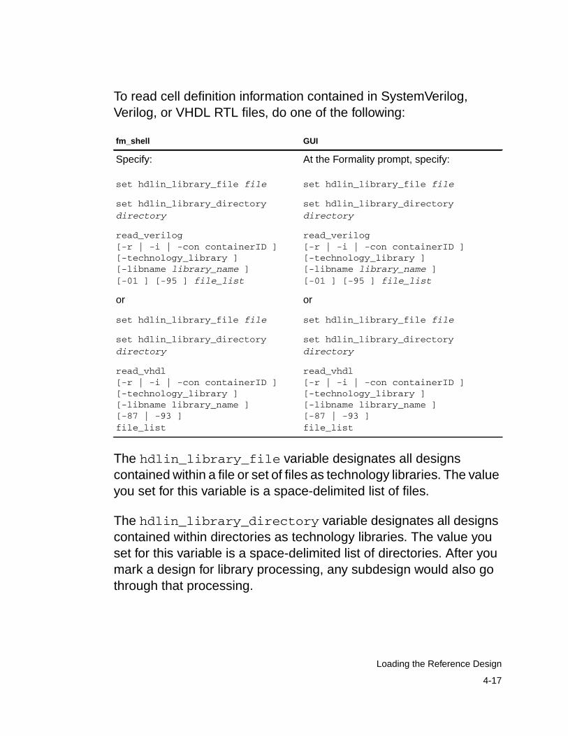
To read cell definition information contained in SystemVerilog,Verilog, or VHDL RTL files, do one of the following:
The hdlin_library_file variable designates all designscontained within a file or set of files as technology libraries. The valueyou set for this variable is a space-delimited list of files.
The hdlin_library_directory variable designates all designscontained within directories as technology libraries. The value youset for this variable is a space-delimited list of directories. After youmark a design for library processing, any subdesign would also gothrough that processing.
fm_shell GUI
Specify:
set hdlin_library_file file
At the Formality prompt, specify:
set hdlin_library_file file
set hdlin_library_directorydirectory
set hdlin_library_directorydirectory
read_verilog[-r | -i | -con containerID ][-technology_library ][-libname library_name ][-01 ] [-95 ] file_list
read_verilog[-r | -i | -con containerID ][-technology_library ][-libname library_name ][-01 ] [-95 ] file_list
or or
set hdlin_library_file file set hdlin_library_file file
set hdlin_library_directorydirectory
set hdlin_library_directorydirectory
read_vhdl[-r | -i | -con containerID ][-technology_library ][-libname library_name ][-87 | -93 ]file_list
read_vhdl[-r | -i | -con containerID ][-technology_library ][-libname library_name ][-87 | -93 ]file_list
4-17
Loading the Reference Design
The fm_shell commands are not listed with all their options. Theoptions listed in this table pertain to reading in technology librarydata only. For more information about the options, see the manpages.
Use the -technology_library option to specify that the datagoes into a technology library rather than a design library. This optiondoes not support mixed Verilog and VHDL technology libraries, nordoes it support Verilog technology library cells with mixeduser-defined primitives and synthesizable constructs. When youspecify the -technology_library option, you must also specify-r, -i, or -c.
Verilog Simulation Data
You generally read in Verilog simulation data by specifying the -yoption with the read_verilog command when you read in designs,as discussed in “Reading Design Libraries” on page 4-20. Certainusers, such as ASIC vendors, however, use theread_simulation_library or read_verilog -vcs -ycommand to read in the Verilog simulation data. Either commandallows you to explore the library in detail for validation because itloads all data into Formality and displays all warnings. Thesecapabilities are not necessary for most users.
4-18
Chapter 4: Setting Basic Elements for Design Verification
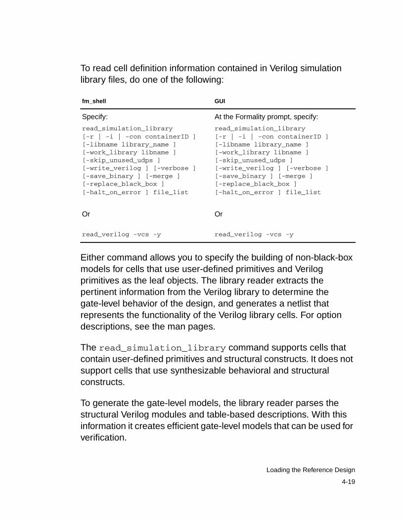
To read cell definition information contained in Verilog simulationlibrary files, do one of the following:
Either command allows you to specify the building of non-black-boxmodels for cells that use user-defined primitives and Verilogprimitives as the leaf objects. The library reader extracts thepertinent information from the Verilog library to determine thegate-level behavior of the design, and generates a netlist thatrepresents the functionality of the Verilog library cells. For optiondescriptions, see the man pages.
The read_simulation_library command supports cells thatcontain user-defined primitives and structural constructs. It does notsupport cells that use synthesizable behavioral and structuralconstructs.
To generate the gate-level models, the library reader parses thestructural Verilog modules and table-based descriptions. With thisinformation it creates efficient gate-level models that can be used forverification.
fm_shell GUI
Specify:
read_simulation_library[-r | -i | -con containerID ][-libname library_name ][-work_library libname ][-skip_unused_udps ][-write_verilog ] [-verbose ][-save_binary ] [-merge ][-replace_black_box ][-halt_on_error ] file_list
Or
read_verilog -vcs -y
At the Formality prompt, specify:
read_simulation_library[-r | -i | -con containerID ][-libname library_name ][-work_library libname ][-skip_unused_udps ][-write_verilog ] [-verbose ][-save_binary ] [-merge ][-replace_black_box ][-halt_on_error ] file_list
Or
read_verilog -vcs -y
4-19
Loading the Reference Design
A Verilog simulation library is intended for simulation, not synthesis.Therefore, the library reader might make certain assumptions aboutthe intended gate-level functions of the user-defined primitives in thesimulation model. The library reader generates comprehensivewarning messages about these primitives to help you eliminateerrors and write a more accurate model.
Each warning message is identified by a code. To obtain moreinformation, look at the man page for the code. For example, ifFormality reports “Error: Can’t open file xxxx (FM-016),” you canobtain more information by entering the command man FM-016.
The library reader supports the following features:
• Sequential cells (each master-slave element pair is merged intoa single sequential element)
• User-defined strengths (assign statements, user-definedprimitive instantiations, and built-in primitives)
• Advanced net types: wand, wor, tri0, tri1, and trireg
• Unidirectional transistor primitives: pmos, nmos, cmos, rpmos,rnmos, and rcmos
• Pull primitives (a pull-up or pull-down element is modeled as anassign statement with a value of 1 or 0)
Reading Design Libraries
To read the reference design into the current session, do one of thefollowing, where the -r option indicates the reference design.
4-20
Chapter 4: Setting Basic Elements for Design Verification
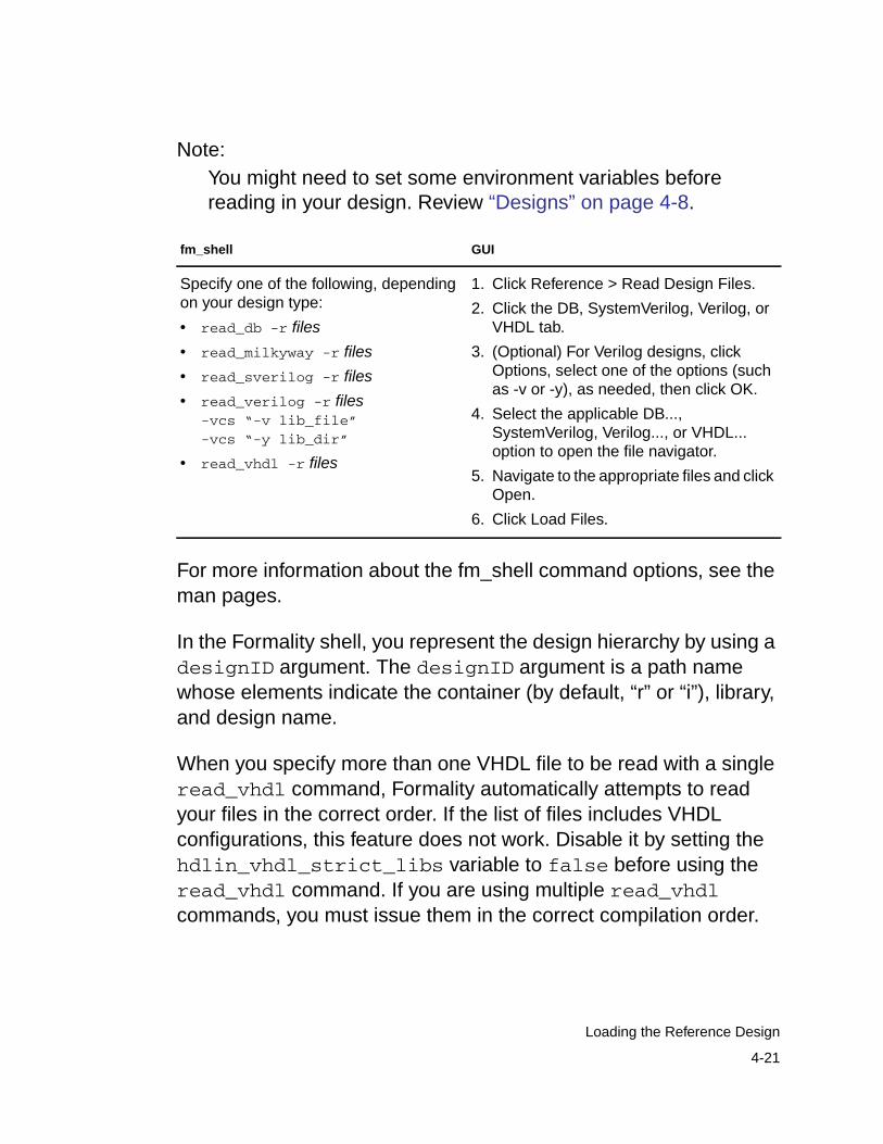
Note:You might need to set some environment variables beforereading in your design. Review “Designs” on page 4-8.
For more information about the fm_shell command options, see theman pages.
In the Formality shell, you represent the design hierarchy by using adesignID argument. The designID argument is a path namewhose elements indicate the container (by default, “r” or “i”), library,and design name.
When you specify more than one VHDL file to be read with a singleread_vhdl command, Formality automatically attempts to readyour files in the correct order. If the list of files includes VHDLconfigurations, this feature does not work. Disable it by setting thehdlin_vhdl_strict_libs variable to false before using theread_vhdl command. If you are using multiple read_vhdlcommands, you must issue them in the correct compilation order.
fm_shell GUI
Specify one of the following, dependingon your design type:
• read_db -r files
• read_milkyway -r files
• read_sverilog -r files
• read_verilog -r files-vcs “-v lib_file”-vcs “-y lib_dir”
• read_vhdl -r files
1. Click Reference > Read Design Files.
2. Click the DB, SystemVerilog, Verilog, orVHDL tab.
3. (Optional) For Verilog designs, clickOptions, select one of the options (suchas -v or -y), as needed, then click OK.
4. Select the applicable DB...,SystemVerilog, Verilog..., or VHDL...option to open the file navigator.
5. Navigate to the appropriate files and clickOpen.
6. Click Load Files.
4-21
Loading the Reference Design
When reading in Verilog designs, you can use thehdlin_auto_netlist variable to specify that Formalityautomatically use the Verilog netlist reader. The default is to use thenetlist reader. Using the Verilog netlist reader can decrease loadingtimes. If the Verilog netlist reader is unsuccessful, Formality uses thedefault Verilog reader.
Use the VCS options -v and -y if you have Verilog simulationlibraries or design modules you want to link to the reference orimplementation designs. These options tell Formality to search in thespecified library or file for unresolved module references. Theseoptions do not support Verilog technology library cells with mixeduser-defined primitives and synthesizable constructs.
Reading in design libraries with one of the commands listed in thepreceding table creates a design library with the default name r:/WORK (or i:/WORK for the implementation design).
Reading Milkyway and .ddc Databases
To read design netlists and technology libraries from Milkyway and.ddc databases, you use the read_milkyway and read_ddccommands, respectively. These commands allow Formality to readdesign information, including netlists and technology libraries, fromMilkyway databases produced by Astro and from .ddc databasesproduced by Design Compiler in XG mode.
4-22
Chapter 4: Setting Basic Elements for Design Verification
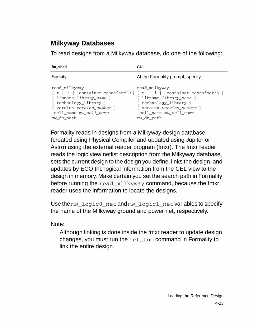
Milkyway Databases
To read designs from a Milkyway database, do one of the following:
Formality reads in designs from a Milkyway design database(created using Physical Compiler and updated using Jupiter orAstro) using the external reader program (fmxr). The fmxr readerreads the logic view netlist description from the Milkyway database,sets the current design to the design you define, links the design, andupdates by ECO the logical information from the CEL view to thedesign in memory. Make certain you set the search path in Formalitybefore running the read_milkyway command, because the fmxrreader uses the information to locate the designs.
Use the mw_logic0_net and mw_logic1_net variables to specifythe name of the Milkyway ground and power net, respectively.
Note:Although linking is done inside the fmxr reader to update designchanges, you must run the set_top command in Formality tolink the entire design.
fm_shell GUI
Specify:
read_milkyway[-r | -i | -container containerID ][-libname library_name ][-technology_library ][-version version_number ]-cell_name mw_cell_namemw_db_path
At the Formality prompt, specify:
read_milkyway[-r | -i | -container containerID ][-libname library_name ][-technology_library ][-version version_number ]-cell_name mw_cell_namemw_db_path
4-23
Loading the Reference Design
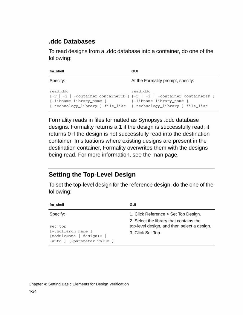
.ddc Databases
To read designs from a .ddc database into a container, do one of thefollowing:
Formality reads in files formatted as Synopsys .ddc databasedesigns. Formality returns a 1 if the design is successfully read; itreturns 0 if the design is not successfully read into the destinationcontainer. In situations where existing designs are present in thedestination container, Formality overwrites them with the designsbeing read. For more information, see the man page.
Setting the Top-Level Design
To set the top-level design for the reference design, do the one of thefollowing:
fm_shell GUI
Specify:
read_ddc[-r | -i | -container containerID ][-libname library_name ][-technology_library ] file_list
At the Formality prompt, specify:
read_ddc[-r | -i | -container containerID ][-libname library_name ][-technology_library ] file_list
fm_shell GUI
Specify:
set_top[-vhdl_arch name ][moduleName | designID |-auto ] [-parameter value ]
1. Click Reference > Set Top Design.
2. Select the library that contains thetop-level design, and then select a design.
3. Click Set Top.
4-24
Chapter 4: Setting Basic Elements for Design Verification
If you are elaborating VHDL and you have more than onearchitecture, use the -vhdl_architecture option. For optiondescriptions, see the man page.
The set_top command tells Formality to set and link the top-leveldesign. If you are using the default “r” and “i” containers, thiscommand also sets the top-level design as the reference orimplementation design. Be aware of the following:
• After you start reading in a reference or implementation design,you must finish before specifying the set_top command. Inaddition, you cannot start reading in the implementation designuntil you have specified set_top for the reference design.
• The set_top command always applies to the design data justpreviously read into Formality (whether it is the implementation orreference design). You receive an error if you specify a designthat you have not loaded.
• You cannot save, restore, or verify a design until you havespecified the set_top command.
• Be sure that the module or design you specify is your top design.If not, you must remove the reference design and start over. Thisalso holds true when you are loading the implementation design.
• Use the -auto option if the top-level design is unambiguous. Yougenerally specify a module or design by name in cases whereyou do not want the actual top-level design to be considered thetop for the current session or when you have multiple modulesthat could be considered at the top level.
• Set the top-level design to the highest level you plan to work within the current session.
4-25
Loading the Reference Design

• After you set the top-level design, you cannot change it, whereasyou can change the reference or implementation design to beverified with the set_reference_design,set_implementation_design, or verify command. Thedesign you specify must reside within the top-level design.
To set parameters in your top-level design, use the -parametersoption to the set_top command. Use this option to specify a newvalue for your design parameters. You can set the parameter only onthe top-level design. Parameters must be Verilog parameters orVHDL generics on the design you are setting them on. Theparameter values can either be integers or specified in the format<param_name> <hex value format> <base>’h<value>. ForVHDL designs, the generics might have the following data types forthe parameter value:
• integer
• bit
• bit_vector
• std_ulogic
• std_ulogic_vector
• std_logic
• std_logic_vector
• signed (std_logic_arith and numeric_std)
• unsigned (std_logic_arith and numeric_std)
For additional information about setting parameters, see theset_top man page.
4-26
Chapter 4: Setting Basic Elements for Design Verification
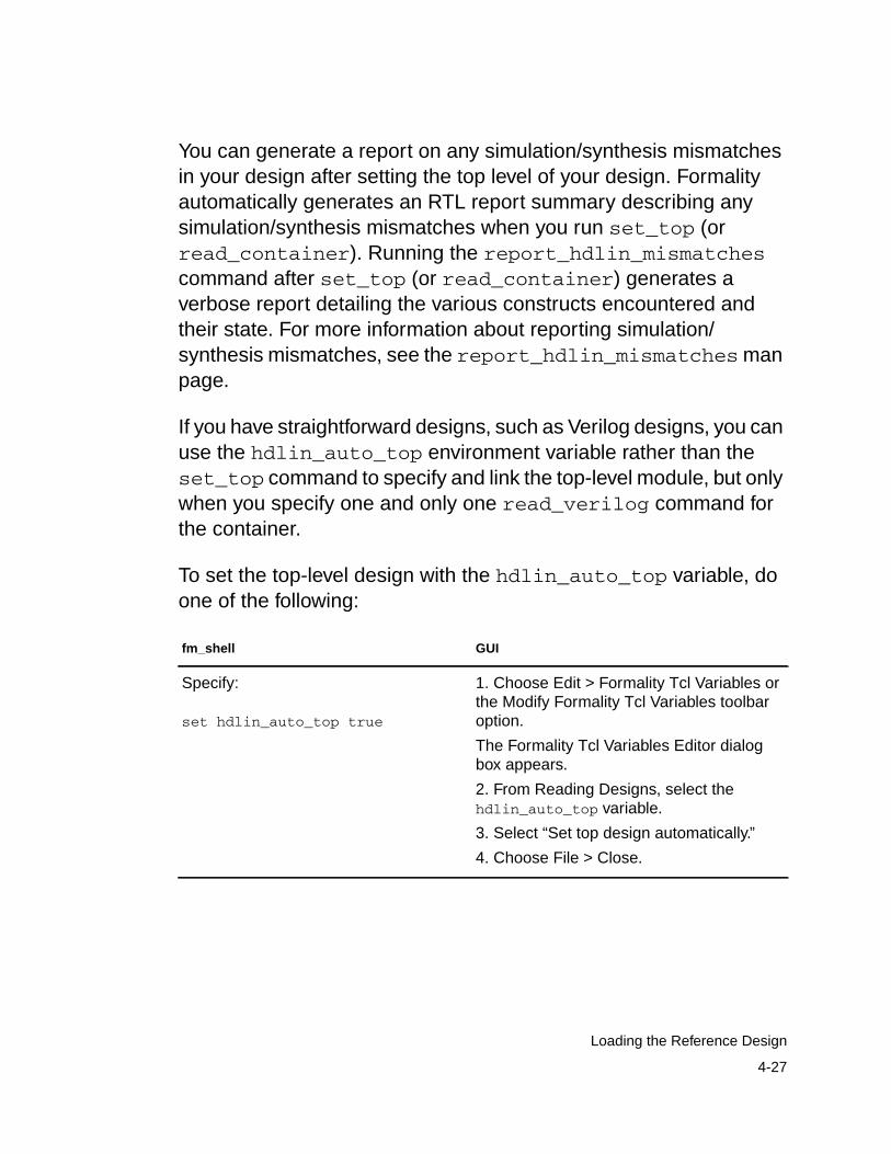
You can generate a report on any simulation/synthesis mismatchesin your design after setting the top level of your design. Formalityautomatically generates an RTL report summary describing anysimulation/synthesis mismatches when you run set_top (orread_container). Running the report_hdlin_mismatchescommand after set_top (or read_container) generates averbose report detailing the various constructs encountered andtheir state. For more information about reporting simulation/synthesis mismatches, see the report_hdlin_mismatchesmanpage.
If you have straightforward designs, such as Verilog designs, you canuse the hdlin_auto_top environment variable rather than theset_top command to specify and link the top-level module, but onlywhen you specify one and only one read_verilog command forthe container.
To set the top-level design with the hdlin_auto_top variable, doone of the following:
fm_shell GUI
Specify:
set hdlin_auto_top true
1. Choose Edit > Formality Tcl Variables orthe Modify Formality Tcl Variables toolbaroption.
The Formality Tcl Variables Editor dialogbox appears.
2. From Reading Designs, select thehdlin_auto_top variable.
3. Select “Set top design automatically.”
4. Choose File > Close.
4-27
Loading the Reference Design
The hdlin_auto_top variable causes Formality to determine thetop-level module and automatically link to it. This variable appliesonly when you are reading in a Verilog design. If you are reading intechnology libraries, Formality ignores this variable.
Formality issues an error if it cannot determine the top-level design.In this case, you must explicitly specify the top design with theset_top command.
If there are multiple VHDL configurations or architectures that couldbe considered the top level, Formality issues a warning and sets thetop-level design to the default architecture.
The hdlin_auto_top variable requires you to use a single readcommand to load the design. You cannot use it for mixed-languagedesigns or for designs that use multiple design libraries or multiplearchitectures or configurations.
Loading the Implementation Design
This section provides an overview of the read-design process flowfor the implementation design. The process for loading theimplementation design is nearly identical to that described in“Loading the Reference Design” on page 4-15. See that section formore information.
Note:If you already specified a .db library for the reference design, it isautomatically shared with the implementation design.
Many Formality shell commands can operate on either the referenceor implementation design. These commands all have a switch toindicate which design container is used for that command. The -r
4-28
Chapter 4: Setting Basic Elements for Design Verification
switch refers to the reference design or container. The -i switchrefers to the implementation design or container. Reading theimplementation design uses the exact same procedures andcommands as reading the reference design, only the switch isdifferent. You can use the -i option to specify the implementationcontainer or use the -c container_name option to provide aspecific container name. From within the GUI, use theImplementation tab to read an implementation design.
For information about the fm_shell commands and their options,see the man pages. For information about special Verilogconsiderations, see “Verilog Simulation Data” on page 4-18.Otherwise, if you have Verilog simulation data, use the VCS -yoption with the read_verilog command.
Setting Up and Managing Containers
As described in “Containers” on page 1-29, a container is acomplete, self-contained space into which Formality reads designs.Each design to be verified must be stored in its own container. If youfollow the steps described in “Reading in Libraries and Designs” onpage 4-3, Formality uses default containers named “r” and “i.”
You generally do not need to work directly with containers. However,Formality allows you the option if, for example,
• You want to read your reference and implementation designs intonames you specify rather than the default “r” and “i”
• You require backwards compatibility with existing Formalityscripts
• You apply user-defined external constraints on your designs
4-29
Setting Up and Managing Containers
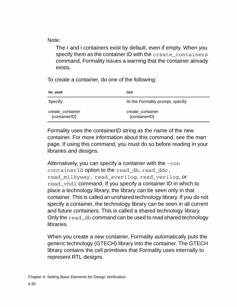
Note:The r and i containers exist by default, even if empty. When youspecify them as the container ID with the create_containerscommand, Formality issues a warning that the container alreadyexists.
To create a container, do one of the following:
Formality uses the containerID string as the name of the newcontainer. For more information about this command, see the manpage. If using this command, you must do so before reading in yourlibraries and designs.
Alternatively, you can specify a container with the -concontainerID option to the read_db, read_ddc,read_milkyway, read_sverilog, read_verilog, orread_vhdl command. If you specify a container ID in which toplace a technology library, the library can be seen only in thatcontainer. This is called an unshared technology library. If you do notspecify a container, the technology library can be seen in all currentand future containers. This is called a shared technology library.Only the read_db command can be used to read shared technologylibraries.
When you create a new container, Formality automatically puts thegeneric technology (GTECH) library into the container. The GTECHlibrary contains the cell primitives that Formality uses internally torepresent RTL designs.
fm_shell GUI
Specify:
create_container [containerID]
At the Formality prompt, specify:
create_container [containerID]
4-30
Chapter 4: Setting Basic Elements for Design Verification
In fm_shell, Formality considers one design the “current” design.When you create or read into a container, it becomes the “currentcontainer.”
After the current container is set, you cannot operate on any othercontainer until you do one of the following:
• Specify set_top for the current container.
• Specify remove_container to remove the container and itscontents. For the default r and i containers, this command merelyremoves the contents.
In the GUI, the concept of a current container does not apply directly.You simply work on the reference and implementation designs. Youcan execute Formality shell commands that rely on the currentcontainer concept. However, the GUI recognizes only the containersthat store the reference and implementation designs. To view a thirddesign in the GUI, you must choose it as a reference orimplementation design.
Note:When you create a new container, Formality automatically addsany shared technology libraries. If you do not want a particularshared technology library in the new container, you mustspecifically remove it.
The write_container and save_session commands will notbe executed if you have not used the set_top command to link thetop-level design.
In the GUI, you can view the reference and implementationcontainers by choosing Designs > Show Reference and Designs >Show Implementation. Choose File > Save to save the design.
4-31
Setting Up and Managing Containers

4-32
Chapter 4: Setting Basic Elements for Design Verification
5Preparing the Design for Verification 5
After reading designs into the Formality environment and linkingthem, you generally need to set design-specific options to helpFormality perform verification. For example, if you are aware ofcertain areas in a design that Formality cannot verify, you might wantto prevent the tool from attempting to verify those areas. Or, if youwant to speed up verification, you might declare blocks in twoseparate designs black boxes.
This chapter points out aspects you should consider in order tooptimize your design for verification. Examples are black boxes,equivalences, external constraints, and don’t care cells. The chapterincludes the following sections:
• Using Don’t Care Cells
• Setting Up Designs
• Removing Information
5-1
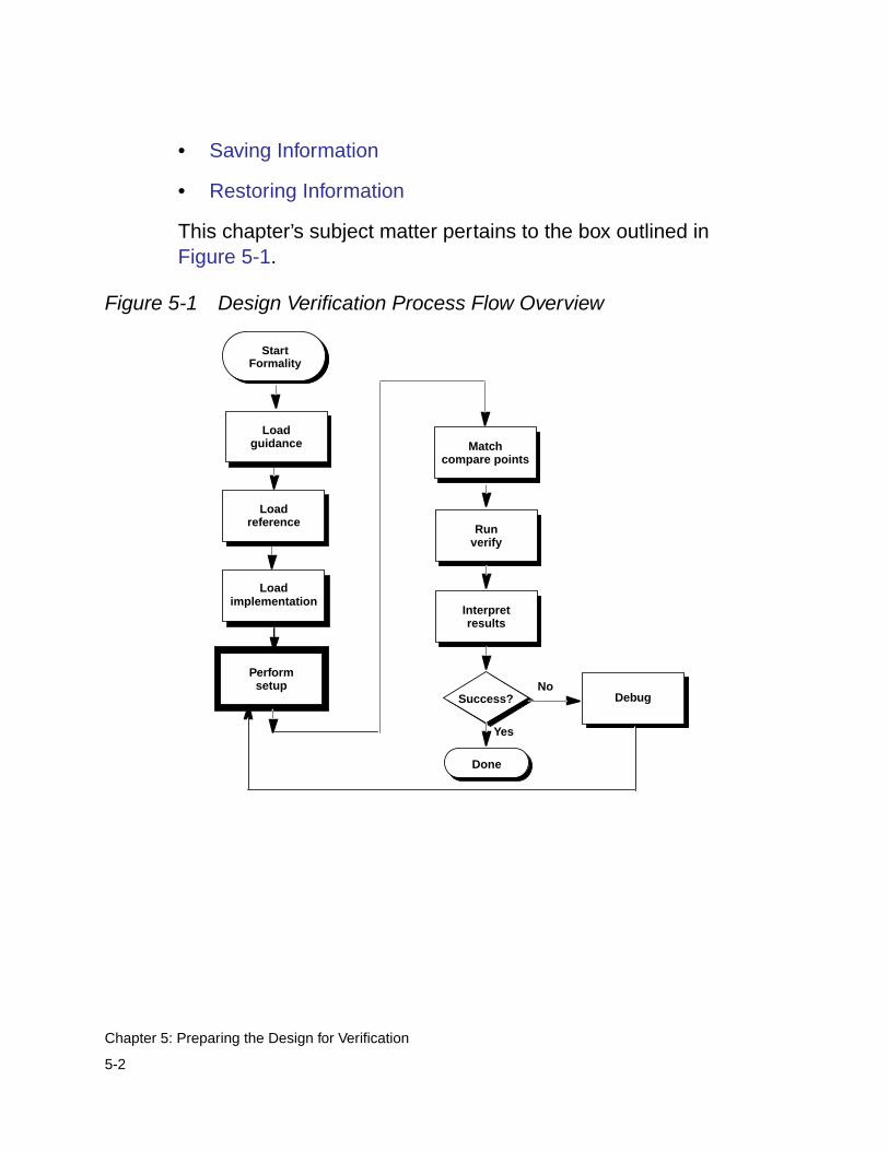
• Saving Information
• Restoring Information
This chapter’s subject matter pertains to the box outlined inFigure 5-1.
Figure 5-1 Design Verification Process Flow Overview
Interpretresults
Performsetup
Runverify
Success?No
Yes
Done
Matchcompare points
Loadreference
Loadimplementation
Debug
StartFormality
Loadguidance
5-2
Chapter 5: Preparing the Design for Verification
Using Don’t Care Cells
Don’t care conditions are input patterns for which the function of adesign or block is not defined. Prior to verification you must definedon’t care conditions as necessary.
There are three ways to create don’t care conditions:
• Explicitly in the design. For input patterns that you do not expectto occur, you can specify the output values as X (don’t care)rather than 0 or 1 in the HDL description of the design.
• Implicitly in the design. In the HDL description, you can specifythe output values for certain combinations of input values and notfor others. The output values for the unspecified combinations ofinput values are don’t care.
• User-specified in Formality. In Formality, you can insertuser-defined don’t care values into the verification by applyingexternal constraints to the design. For example, you canconstrain an input bus so that Formality considers only “one-hot”values for that bus during verification. “One-hot” means thatexactly one bit is 1 and all others are 0 on the bus. For moreinformation, see “Working With External Constraints” onpage 5-30.
When Formality encounters a don’t care condition, it models thelogic by using an extra cell called a don’t care cell. This cell has twoinputs, dc (don’t care) and f (function), and a single output. When thedc input is 0, the f input is passed through to the output unchanged.When the dc input is 1, the f input is ignored and the output value isX (don’t care).
5-3
Using Don’t Care Cells
In the consistency verification mode (the default), the value X is thedon’t care parameter in the reference design and unknown in theimplementation design. Therefore, the value 0, 1, or X in theimplementation design is considered equivalent to an X in thereference design.
If it is important for the implementation design to have the same don’tcare set as the reference design, use the equality (rather thanconsistency) verification mode. In the equality mode, all don’t careconditions must match exactly between the reference andimplementation designs to pass verification. Doing this isappropriate only when both the implementation and referencedesigns are RTL designs, because gate-level designs do not havedon’t care information.
Setting Up Designs
How to set up your designs for verification is described in thefollowing sections. Depending on your design, you might not performall of the operations described.
• Supporting Multibit Library Cells
• Resolving Nets With Multiple Drivers
• Eliminating Asynchronous State-Holding Loops
• Working With Black Boxes
• Working With Constants
• Working With Equivalences
• Working With External Constraints
5-4
Chapter 5: Preparing the Design for Verification
• Working With Hierarchical Designs
• Working With Combinational Design Changes
• Working With Sequential Design Changes
• Working With Reencoded Finite State Machines
• Working With Retimed Designs
• Working With Single-State Holding Elements
• Working With System Functions for Low-Power Design
• Working with Retention Registers without RTL System Functionsfor Low Power Design
• Working With Multiplier Architectures
• Working With Automated Setup Files
• Automated Setup File Diagnostic Messages
• Automated Setup File Conversion to Text
Supporting Multibit Library Cells
Formality supports the use of multibit library cells. You can controlmultibit component inference in Design Compiler by using thehdlin_infer_multibit variable. For more information, see theman page on the hdlin_infer_multibit variable in DesignCompiler. If you choose not to use this capability in Design Compiler,and you manually group register bits into library cells instead, thenyou need to follow certain naming rules. Otherwise, Formality canencounter difficulties in matching compare points where the multibitcomponents are used.
5-5
Setting Up Designs
The following naming rules apply for manually grouping register bitsinto library cells:
• When you group registers into multibit cells, use the syntaxname_number to number to name the grouped cell. Forexample, the name my_reg_7to0 maps to the eight registersnamed my_reg_0, my_reg_1, ... my_reg_7 in the other design.
• If the grouped register contains multiple elements that are not insequential order, you can use syntax in the form ofname_number to number,number,number... Forexample, the name treg_6to4,2 maps to the four registers namedtreg_6, treg_5, treg_4, and treg_2 in the other design. In thissyntax, a comma separates the individual elements of the multibitcell.
Resolving Nets With Multiple Drivers
During verification, Formality ensures that each net with more thanone driver is resolved to the correct function. At the design level, youcan instruct Formality to use resolution functions to resolve thesetypes of nets.
To define net resolution, do one of the following:
fm_shell GUI
Specify:
set_parameters[-resolution function ]designID
1. Choose Setup > Design Parameters.
2. Click the Reference or Implementationtab.
3. Select a library, then a design.
4. Click Consensus, Treat Drivers as BlackBoxes, Wired AND, or Wired OR.
5-6
Chapter 5: Preparing the Design for Verification
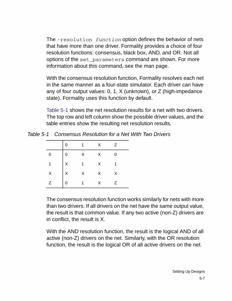
The -resolution function option defines the behavior of netsthat have more than one driver. Formality provides a choice of fourresolution functions: consensus, black box, AND, and OR. Not alloptions of the set_parameters command are shown. For moreinformation about this command, see the man page.
With the consensus resolution function, Formality resolves each netin the same manner as a four-state simulator. Each driver can haveany of four output values: 0, 1, X (unknown), or Z (high-impedancestate). Formality uses this function by default.
Table 5-1 shows the net resolution results for a net with two drivers.The top row and left column show the possible driver values, and thetable entries show the resulting net resolution results.
The consensus resolution function works similarly for nets with morethan two drivers. If all drivers on the net have the same output value,the result is that common value. If any two active (non-Z) drivers arein conflict, the result is X.
With the AND resolution function, the result is the logical AND of allactive (non-Z) drivers on the net. Similarly, with the OR resolutionfunction, the result is the logical OR of all active drivers on the net.
Table 5-1 Consensus Resolution for a Net With Two Drivers
0 1 X Z
0 0 X X 0
1 X 1 X 1
X X X X X
Z 0 1 X Z
5-7
Setting Up Designs
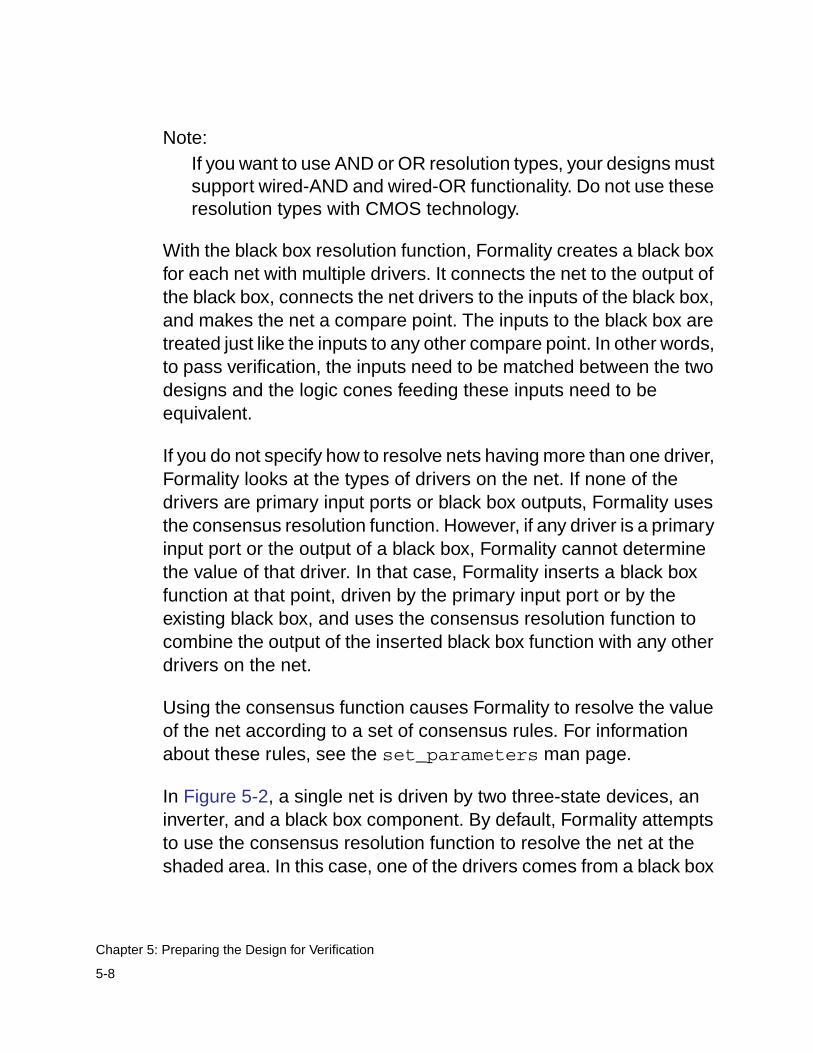
Note:If you want to use AND or OR resolution types, your designs mustsupport wired-AND and wired-OR functionality. Do not use theseresolution types with CMOS technology.
With the black box resolution function, Formality creates a black boxfor each net with multiple drivers. It connects the net to the output ofthe black box, connects the net drivers to the inputs of the black box,and makes the net a compare point. The inputs to the black box aretreated just like the inputs to any other compare point. In other words,to pass verification, the inputs need to be matched between the twodesigns and the logic cones feeding these inputs need to beequivalent.
If you do not specify how to resolve nets having more than one driver,Formality looks at the types of drivers on the net. If none of thedrivers are primary input ports or black box outputs, Formality usesthe consensus resolution function. However, if any driver is a primaryinput port or the output of a black box, Formality cannot determinethe value of that driver. In that case, Formality inserts a black boxfunction at that point, driven by the primary input port or by theexisting black box, and uses the consensus resolution function tocombine the output of the inserted black box function with any otherdrivers on the net.
Using the consensus function causes Formality to resolve the valueof the net according to a set of consensus rules. For informationabout these rules, see the set_parameters man page.
In Figure 5-2, a single net is driven by two three-state devices, aninverter, and a black box component. By default, Formality attemptsto use the consensus resolution function to resolve the net at theshaded area. In this case, one of the drivers comes from a black box
5-8
Chapter 5: Preparing the Design for Verification
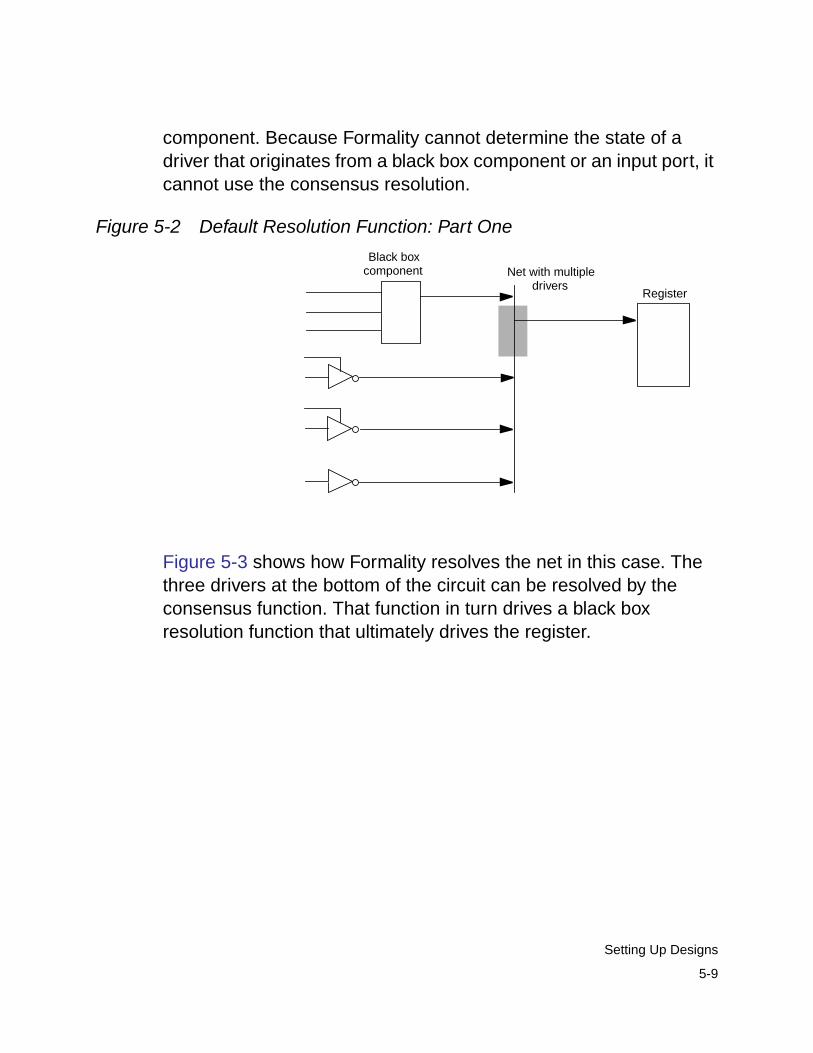
component. Because Formality cannot determine the state of adriver that originates from a black box component or an input port, itcannot use the consensus resolution.
Figure 5-2 Default Resolution Function: Part One
Figure 5-3 shows how Formality resolves the net in this case. Thethree drivers at the bottom of the circuit can be resolved by theconsensus function. That function in turn drives a black boxresolution function that ultimately drives the register.
Black boxcomponent Net with multiple
driversRegister
5-9
Setting Up Designs
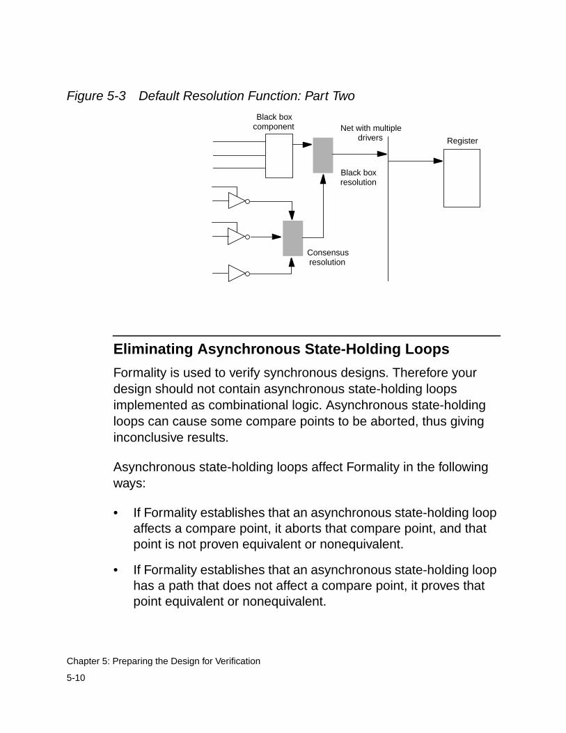
Figure 5-3 Default Resolution Function: Part Two
Eliminating Asynchronous State-Holding Loops
Formality is used to verify synchronous designs. Therefore yourdesign should not contain asynchronous state-holding loopsimplemented as combinational logic. Asynchronous state-holdingloops can cause some compare points to be aborted, thus givinginconclusive results.
Asynchronous state-holding loops affect Formality in the followingways:
• If Formality establishes that an asynchronous state-holding loopaffects a compare point, it aborts that compare point, and thatpoint is not proven equivalent or nonequivalent.
• If Formality establishes that an asynchronous state-holding loophas a path that does not affect a compare point, it proves thatpoint equivalent or nonequivalent.
Black boxcomponent
Register
Black boxresolution
Consensusresolution
Net with multipledrivers
5-10
Chapter 5: Preparing the Design for Verification
• If Formality cannot establish that an asynchronous state-holdingloop has a path that does not affect a compare point, it aborts thatcompare point, and that point is not proven equivalent ornonequivalent.
Formality automatically breaks loops during verification if they areidentical. To change this behavior, set theverification_auto_loop_break variable to false. Forinformation about this variable, see the man page.
Note:You can also specify the report_loops command afterverification. In this case, Formality reports the original loops evenif they were automatically broken during verification.
To report asynchronous state-holding loops, do one of the following:
By default, the report_loops command returns a list of nets andpins for loops in both the reference and implementation designs. Itreports 10 loops per design and 100 design objects per loop unlessyou specify otherwise with the -limit option. Objects are reportedusing instance-based path names.
Use the -unfold option to report subloops embedded within a loopindividually. Otherwise, they are reported together.
fm_shell GUI
Specify:
report_loops [-ref ] [-impl ][-limit N ] [-unfold ]
At the Formality prompt, specify:
report_loops [-ref ] [-impl ][-limit N ] [-unfold ]
5-11
Setting Up Designs
If a loop is completely contained in a technology library cell, thiscommand lists all the nets and pins associated with it. If only part ofa loop belongs to a technology library cell, the cell name does notappear in the list. In addition, the report displays the hierarchicalstructure if a loop crosses boundaries.
For more information about the report_loops command, see theman page.
After you determine the locations of any asynchronous state-holdingloops, ensure that Formality successfully verifies the loop circuit byinserting cutpoints, as described in the next section.
Working With Cutpoints
As previously mentioned, Formality uses black box input pins ascompare points. You can also manually insert compare points at aspecific net or hierarchical block pin. Inserting a compare point at aspecific net or hierarchical block pin in a design has the effect ofcreating a new primary output and a new primary input to thedownstream logic. This point is called a cutpoint because iteffectively cuts the net on which it is inserted.
You can use cutpoints to create specific compare points to verifydesigns that contain asynchronous state-holding loops. Settingcutpoints on hierarchical block pins and internal nets allowsFormality to verify these points independently and use them as a freevariable for verification of downstream compare points.
When the design you want to verify has asynchronous state-holdingloops, you can manually break each loop by specifying a net orhierarchical block pin of a cell in the loop, then inserting a cutpoint.Likewise, when you encounter a design that is difficult to verify, youcan simplify the cones under verification by inserting cutpoints at
5-12
Chapter 5: Preparing the Design for Verification
specific nets or hierarchical block pins, thereby creating newcompare points and reducing the size of the logic cones to beverified.
You can refer to the following sources to help you determine a pointin the design that is causing (or is likely to cause) a verificationproblem:
• Your prior knowledge of loops in the circuit design. If you properlyinsert cutpoints from the start, you can avoid the time spent ongenerating an inconclusive verification.
• The occurrence of inconclusive verification results. Following theverification run, use the report_loop -ref and report_loop-impl commands to locate the loops.
• Timing loop reports generated by other tools, such as PrimeTimeand Design Compiler.
After you determine the location of a loop in the design, you caninsert cutpoints anywhere in the loop without risk of harming theverification setup. Adding a cutpoint merely introduces a newcompare point that is verified by Formality. Be sure to place cutpointsin exactly the same locations in the reference and implementationdesigns. Use the set_user_match command to match thecorresponding cutpoints.
Creating a Cutpoint
To insert a cutpoint in a design, do one of the following:
fm_shell GUI
Specify:
set_cutpoint objectID[-type objectID_type ]
At the Formality prompt, specify:
set_cutpoint objectID[-type objectID_type ]
5-13
Setting Up Designs
Specify the name of the net or pin along with the design object whereFormality should insert the cutpoint. If the name of the specifieddesign object is associated with more than one type of design object,you must specify the type (either pin or net), using the -type option.For more information about the set_cutpoint command, see theman page.
Reporting Information About Cutpoints
To report the cutpoints inserted with the set_cutpoint command,do one of the following:
For more information about this command, see the man page.
Removing a Cutpoint
To remove cutpoints added with the set_cutpoint command, doone of the following:
fm_shell GUI
Specify:
report_cutpoints
At the Formality prompt, specify:
report_cutpoints
fm_shell GUI
Specify:
remove_cutpoint object_list-type | -all
At the Formality prompt, specify:
remove_cutpoint object_list-type | -all
5-14
Chapter 5: Preparing the Design for Verification
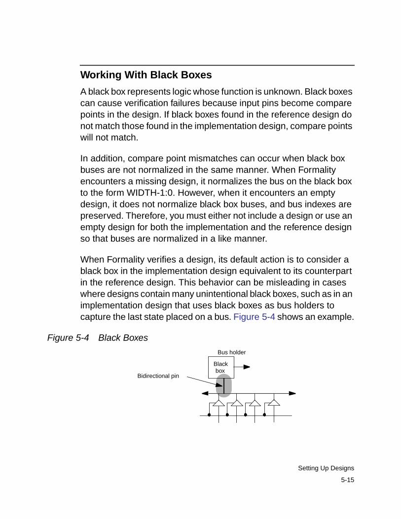
Working With Black Boxes
A black box represents logic whose function is unknown. Black boxescan cause verification failures because input pins become comparepoints in the design. If black boxes found in the reference design donot match those found in the implementation design, compare pointswill not match.
In addition, compare point mismatches can occur when black boxbuses are not normalized in the same manner. When Formalityencounters a missing design, it normalizes the bus on the black boxto the form WIDTH-1:0. However, when it encounters an emptydesign, it does not normalize black box buses, and bus indexes arepreserved. Therefore, you must either not include a design or use anempty design for both the implementation and the reference designso that buses are normalized in a like manner.
When Formality verifies a design, its default action is to consider ablack box in the implementation design equivalent to its counterpartin the reference design. This behavior can be misleading in caseswhere designs contain many unintentional black boxes, such as in animplementation design that uses black boxes as bus holders tocapture the last state placed on a bus. Figure 5-4 shows an example.
Figure 5-4 Black Boxes
Bus holder
Bidirectional pin
Blackbox
5-15
Setting Up Designs
In this example a bidirectional pin is used to connect to the bus.Because this pin is bidirectional, the bus has an extraneous driver. Ifthe reference design does not use similar bus holders, theimplementation design fails verification. To solve this problem, youcan declare the direction “in.” Assigning the pin a single directionremoves the extraneous driver.
By default, Formality stops processing and issues an error if itencounters unresolved designs (those that cannot be found duringthe linking process) and empty designs (those with an interfaceonly). For example, suppose a VHDL design has three instances ofdesigns whose logic is defined through associated architectures. Ifthe architectures are not in the container, Formality halts.
You can use the hdlin_unresolved_modules environmentvariable to cause Formality to create black boxes when it encountersunresolved or empty designs during linking. For more informationabout this variable, see the man page.
Note:Setting the hdlin_unresolved_modules variable to blackbox can cause verification problems.
You can use the verification_ignore_unmatched_implementation_blackbox_input variable to cause Formalityto allow successful verification of unmatched input pins on matchedblack boxes in the implementation design. For more informationabout this variable, see the man page.
Because of the uncertainty that black boxes introduce to verification,Formality allows you some control over how the tool handles them.You can
5-16
Chapter 5: Preparing the Design for Verification
• Load only the design interface (ports and directions) even thoughthe model exists
• Mark a design as a black box for verification even though itsmodel exists and the design is linked
• Report a list of black boxes
• Perform an identity check between comparable black boxes
• Set the port and pin directions
These techniques are described in the following sections.
Loading Design Interfaces
If you know you want an object to be a black box, specify thehdlin_interface_only environment variable rather than loadingnothing into Formality. Formality benefits from having the pin namesand directions supplied by this variable.
Note:Specify the hdlin_interface_only variable before readingin your designs.
To load only the pin names and directions for designs, do one of thefollowing:
fm_shell GUI
Specify:
set hdlin_interface_only"designs"
1. Click Reference or Implementation.
2. Click Options.
3. Click the Variables tab.
4. In the “Read interface only for thesedesigns” box, enter list of designs.
5. Click OK.
5-17
Setting Up Designs
The hdlin_interface_only environment variable allows you toload the specified designs as black boxes, even when their modelsexist. This capability is useful for loading in RAM, intellectualproperty (IP), and other special models. When you specifyreport_black_boxes, these designs are attributed with an “I”(interface only) to indicate that you specified this variable.
This variable supports wildcards. It ignores syntax violations withinspecified designs. However, if Formality cannot create aninterface-only model due to syntax violations in the pin declarations,it treats the specified design as missing.
Modules names must be simple design names. For example, to markall RAMs named SRAM01, SRAM02, and so on in a library as blackboxes, use the following command:
fm_shell (setup)> set hdlin_interface_only "SRAM*"
This variable is not cumulative. Subsequent specifications causeFormality to override prior specifications. Therefore, if you want tomark all RAMs with names starting with DRAM* and SRAM* as blackboxes, for example, specify both on one line.
fm_shell (setup)> set hdlin_interface_only "DRAM* SRAM*"
Marking a Design as a Black Box for Verification
To mark a design as a black box for verification, do one of thefollowing:
fm_shell GUI
Specify:
set_black_box designID
At the Formality prompt, specify:
set_black_box designID
5-18
Chapter 5: Preparing the Design for Verification
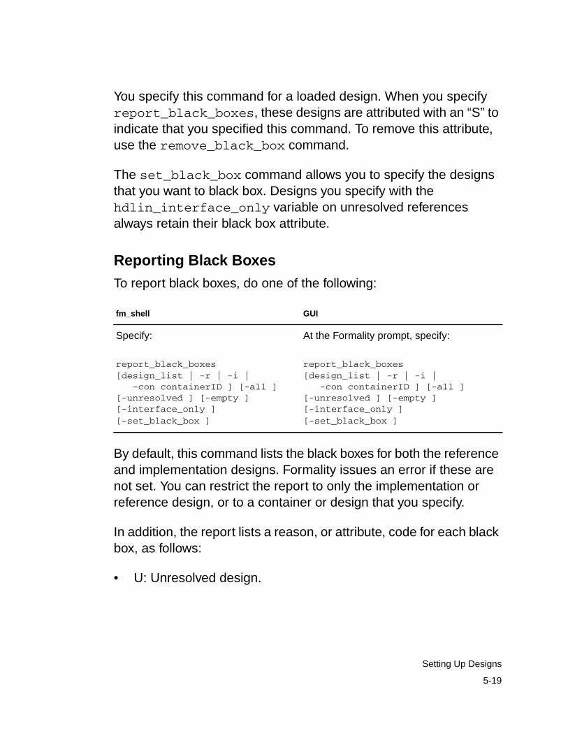
You specify this command for a loaded design. When you specifyreport_black_boxes, these designs are attributed with an “S” toindicate that you specified this command. To remove this attribute,use the remove_black_box command.
The set_black_box command allows you to specify the designsthat you want to black box. Designs you specify with thehdlin_interface_only variable on unresolved referencesalways retain their black box attribute.
Reporting Black Boxes
To report black boxes, do one of the following:
By default, this command lists the black boxes for both the referenceand implementation designs. Formality issues an error if these arenot set. You can restrict the report to only the implementation orreference design, or to a container or design that you specify.
In addition, the report lists a reason, or attribute, code for each blackbox, as follows:
• U: Unresolved design.
fm_shell GUI
Specify:
report_black_boxes[design_list | -r | -i | -con containerID ] [-all ][-unresolved ] [-empty ][-interface_only ][-set_black_box ]
At the Formality prompt, specify:
report_black_boxes[design_list | -r | -i | -con containerID ] [-all ][-unresolved ] [-empty ][-interface_only ][-set_black_box ]
5-19
Setting Up Designs
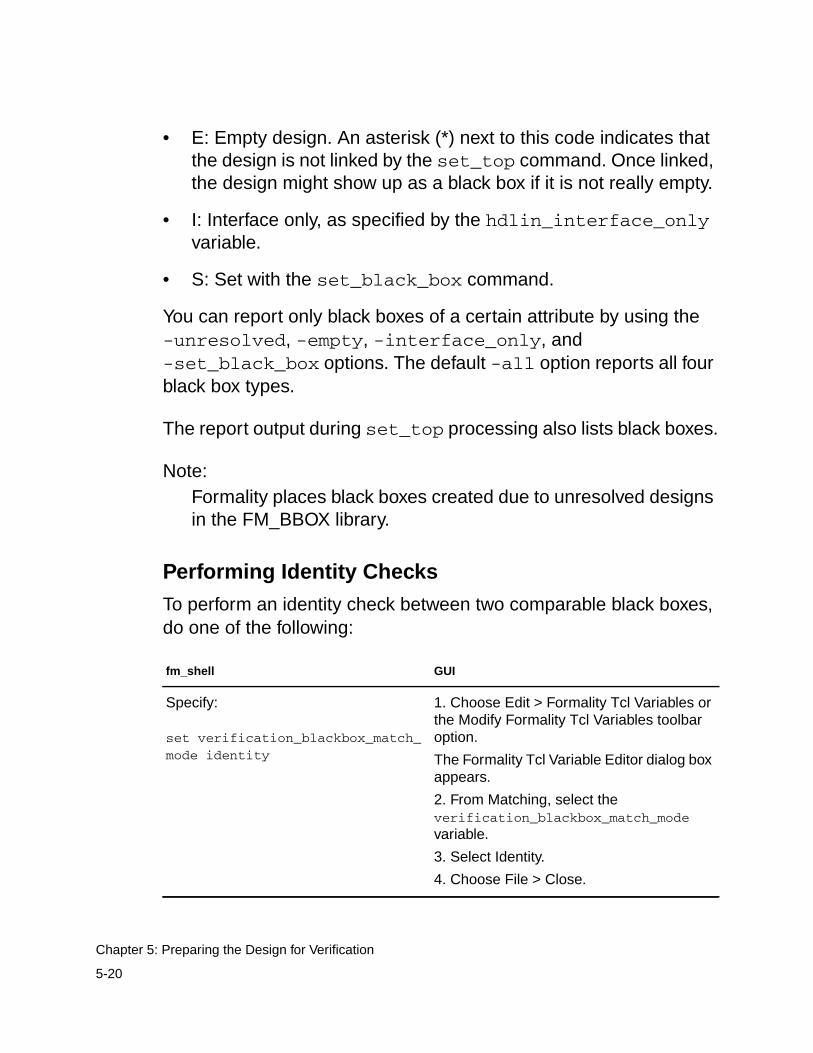
• E: Empty design. An asterisk (*) next to this code indicates thatthe design is not linked by the set_top command. Once linked,the design might show up as a black box if it is not really empty.
• I: Interface only, as specified by the hdlin_interface_onlyvariable.
• S: Set with the set_black_box command.
You can report only black boxes of a certain attribute by using the-unresolved, -empty, -interface_only, and-set_black_box options. The default -all option reports all fourblack box types.
The report output during set_top processing also lists black boxes.
Note:Formality places black boxes created due to unresolved designsin the FM_BBOX library.
Performing Identity Checks
To perform an identity check between two comparable black boxes,do one of the following:
fm_shell GUI
Specify:
set verification_blackbox_match_mode identity
1. Choose Edit > Formality Tcl Variables orthe Modify Formality Tcl Variables toolbaroption.
The Formality Tcl Variable Editor dialog boxappears.
2. From Matching, select theverification_blackbox_match_modevariable.
3. Select Identity.
4. Choose File > Close.
5-20
Chapter 5: Preparing the Design for Verification
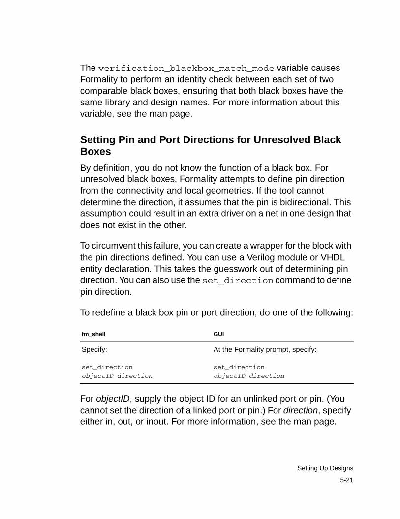
The verification_blackbox_match_mode variable causesFormality to perform an identity check between each set of twocomparable black boxes, ensuring that both black boxes have thesame library and design names. For more information about thisvariable, see the man page.
Setting Pin and Port Directions for Unresolved BlackBoxes
By definition, you do not know the function of a black box. Forunresolved black boxes, Formality attempts to define pin directionfrom the connectivity and local geometries. If the tool cannotdetermine the direction, it assumes that the pin is bidirectional. Thisassumption could result in an extra driver on a net in one design thatdoes not exist in the other.
To circumvent this failure, you can create a wrapper for the block withthe pin directions defined. You can use a Verilog module or VHDLentity declaration. This takes the guesswork out of determining pindirection. You can also use the set_direction command to definepin direction.
To redefine a black box pin or port direction, do one of the following:
For objectID, supply the object ID for an unlinked port or pin. (Youcannot set the direction of a linked port or pin.) For direction, specifyeither in, out, or inout. For more information, see the man page.
fm_shell GUI
Specify:
set_directionobjectID direction
At the Formality prompt, specify:
set_directionobjectID direction
5-21
Setting Up Designs
Working With Constants
Formality recognizes two types of constants: design anduser-defined. Design constants are nets in your design that are tiedto a logic 1 or 0 value. User-defined constants are ports or nets towhich you attach a logic 1 or 0 value, using Formality commands.
User-defined constants are especially helpful when several problemareas exist in a circuit and you want to isolate a particular troublespot by disabling an area of logic. For example, suppose yourimplementation design has scan logic and you do not want toconsider it in the verification process. You can assign a constant tothe scan-enable input port to disable the scan logic and take it out ofthe verification process.
You can apply a user-defined constant to a port or net. However, ifyou assign a constant to a net with a driver, Formality displays awarning message.
Formality tracks all user-defined constants and enables you togenerate reports on them. You can specify how Formalitypropagates constants through different levels of the designhierarchy.
You can define constant states on ports or nets within a design torestrict the scope of a verification. This technique is useful when youhave designs that contain scan logic and you want to disable thatlogic during verification. For example, you can define a constant todisable a scan enable line and thus verify the design in missionmode.
You can manage user-defined constants by performing the tasks inthe following sections.
5-22
Chapter 5: Preparing the Design for Verification
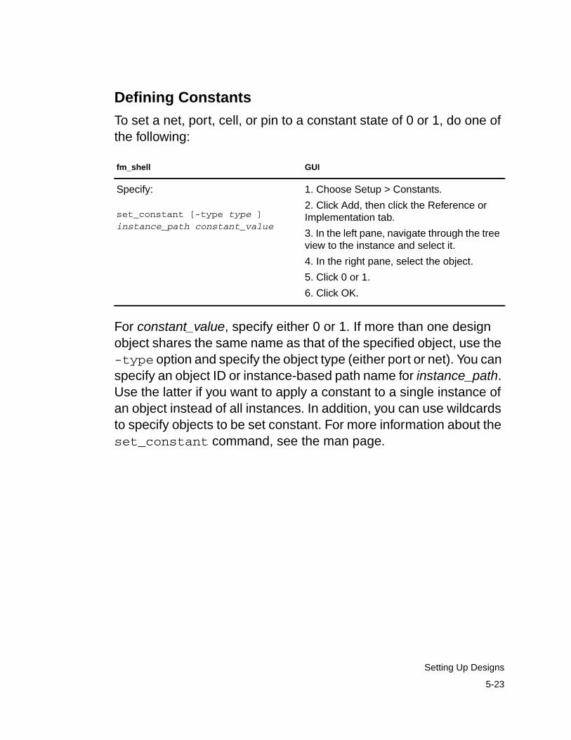
Defining Constants
To set a net, port, cell, or pin to a constant state of 0 or 1, do one ofthe following:
For constant_value, specify either 0 or 1. If more than one designobject shares the same name as that of the specified object, use the-type option and specify the object type (either port or net). You canspecify an object ID or instance-based path name for instance_path.Use the latter if you want to apply a constant to a single instance ofan object instead of all instances. In addition, you can use wildcardsto specify objects to be set constant. For more information about theset_constant command, see the man page.
fm_shell GUI
Specify:
set_constant [-type type ]instance_path constant_value
1. Choose Setup > Constants.
2. Click Add, then click the Reference orImplementation tab.
3. In the left pane, navigate through the treeview to the instance and select it.
4. In the right pane, select the object.
5. Click 0 or 1.
6. Click OK.
5-23
Setting Up Designs
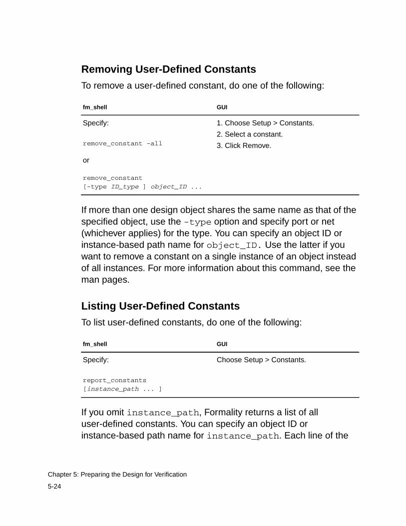
Removing User-Defined Constants
To remove a user-defined constant, do one of the following:
If more than one design object shares the same name as that of thespecified object, use the -type option and specify port or net(whichever applies) for the type. You can specify an object ID orinstance-based path name for object_ID. Use the latter if youwant to remove a constant on a single instance of an object insteadof all instances. For more information about this command, see theman pages.
Listing User-Defined Constants
To list user-defined constants, do one of the following:
If you omit instance_path, Formality returns a list of alluser-defined constants. You can specify an object ID orinstance-based path name for instance_path. Each line of the
fm_shell GUI
Specify:
remove_constant -all
or
remove_constant[-type ID_type ] object_ID ...
1. Choose Setup > Constants.
2. Select a constant.
3. Click Remove.
fm_shell GUI
Specify:
report_constants[instance_path ... ]
Choose Setup > Constants.
5-24
Chapter 5: Preparing the Design for Verification
report shows the constant value, design object type, and designobject name. For information about this command, see the manpage.
Working With Equivalences
You might want to declare two design objects as equivalent. You canuse the set_user_match command to match one object in thereference design to many objects in the implementation design. Forexample, suppose the reference design has a single clock port, andthe implementation design has several clock ports. You would useset_user_match to match all of the implementation ports to thereference port.
To make an equivalence declaration, use the set_equivalencecommand. The set_equivalence command declares a pair ofnets or ports to be equivalent in the reference and implementationdesigns. You can also declare a pair of ports, pins, or nets in thesame design as equivalent; therefore, when two pins are set asequivalent, the second pin uses the value of the first pin.
In the case of a net, Formality disconnects the net from the driver inthe implementation design and then reconnects that net to thecorresponding driver in the reference design. The net in theimplementation design is now driven by the equivalent net in thereference design. Most importantly, this means that any logic drivingthe net in the implementation design is not verified. The same is truefor two input ports declared to be equivalent.
5-25
Setting Up Designs
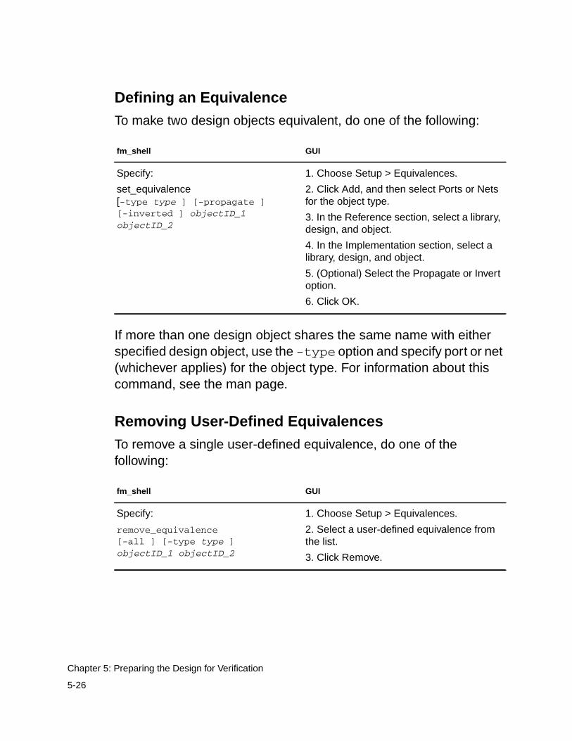
Defining an Equivalence
To make two design objects equivalent, do one of the following:
If more than one design object shares the same name with eitherspecified design object, use the -type option and specify port or net(whichever applies) for the object type. For information about thiscommand, see the man page.
Removing User-Defined Equivalences
To remove a single user-defined equivalence, do one of thefollowing:
fm_shell GUI
Specify:
set_equivalence[-type type ] [-propagate ][-inverted ] objectID_1objectID_2
1. Choose Setup > Equivalences.
2. Click Add, and then select Ports or Netsfor the object type.
3. In the Reference section, select a library,design, and object.
4. In the Implementation section, select alibrary, design, and object.
5. (Optional) Select the Propagate or Invertoption.
6. Click OK.
fm_shell GUI
Specify:
remove_equivalence[-all ] [-type type ]objectID_1 objectID_2
1. Choose Setup > Equivalences.
2. Select a user-defined equivalence fromthe list.
3. Click Remove.
5-26
Chapter 5: Preparing the Design for Verification
If more than one design object shares the same name as a specifieditem, use the -type option and specify port or net (whicheverapplies) for the type. For more information about this command, seethe man page.
Listing User-Defined Equivalences
To list user-defined equivalences, do one of the following:
Formality produces a list of user-defined equivalences for designs,ports, and nets. For more information about this command, see theman page.
Using Verilog 2001 Constructs. You can perform equivalencychecking on designs that incorporate commonly used Verilog 2001constructs. These constructs include, but are not limited to,
• Indexed vector part
• Signed arithmetic extensions
• Power operator
• Combinational logic sensitivity token
• Automatic width extensions
• Combined port and data type declarations
• American National Standards Institute (ANSI) style of input andoutput declarations
fm_shell GUI
Specify:
report_equivalences
Choose Setup > Equivalences.
5-27
Setting Up Designs
The following sections describe and provide examples for each of thesupported Verilog 2001 constructs.
Indexed Vector Part
Indexed vector part selects are supported. Formality allows indexedpart select, a base expression, and an offset direction. For instance,the following is allowed:
[base_expr +: width_expr][base_expr -: width_expr]wire [7:0] byteN = word[byte_num*8 +: 8]
Signed Arithmetic Extensions
Formality accepts signed arithmetic extensions: data type, systemfunction ($signed, $unsigned), and arithmetic shift operators (>>>and <<<). Data type support includes register and net data types andports and functions to be declared as signed types. System functionsupport includes $signed and $unsigned that are used to convertsigned values to unsigned and vice versa. Arithmetic shift operatorsupport maintains the sign of a value by filling in the signed-bit valueas it shifts.
This example shows a signed data type:
reg signed [63a:0] data;wire signed [7:0] vector;input signed [31:0] a;function signed [128:0] alu;
This example shows a system function:
reg [63:0] a; //unsigned data typealways @(a) begin result1 = a + 2; //unsigned result2 = $signed(a) +2; //signedend
5-28
Chapter 5: Preparing the Design for Verification
This example shows arithmetic shift operators:
D >> 3 //logical shift yields 8’b00010100D >>> 3 //arithmetic shift yields 8;b11110100
Power Operator
Formality accepts a power operator that is similar to the C pow ()function. This is useful when you need the power operator tocalculate values, such as a2. An example of a power operator is
always @(posedge clock)result = base ** exponent;
Combinational Logic Sensitivity Token
Formality now accepts the combinational logic sensitivity token. Thistoken (@*) represents a logic sensitivity list, indicating that statementgroups should automatically be sensitive to changes on any valuesread in that group. An example of this is
always @* //combinational logicif (sel) y = a;else y = b;
Automatic Width Extensions
Formality can handle automatic width extensions beyond 32 bits.Therefore, an unsized value of Z or X automatically expands to fill thefull width of the vector on the left side of the argument. An exampleshowing how Formality handles automatic width extensions is
parameter WIDTH = 64;reg [WIDTH-1:0] data;data = ‘bz; //fills with ‘hzzzzzzzzzzzzzzzzzz
5-29
Setting Up Designs
Combined Port and Data Type Declarations
Formality accepts declarations that combine the direction of the portand data type of that signal into one statement. The following showsan example of this:
module mux8 (y, a, b, en);output reg [7:0] y;input wire [7:0] a, b;input wire en;
ANSI C-Style Module Input and Output Declarations
Formality supports ANSI C-style port declarations for modules. Anexample of this is
module mux8 (output reg [7:0) y,output reg [7:0] a,input wire [7:0] b,input wire en );
Working With External Constraints
Sometimes you might want to restrict the inputs used for verificationby setting an external constraint. By setting an external constraint,you can limit the potential differences between two designs byeliminating unused combinations of input values from consideration,thereby reducing verification time and eliminating potential falsefailures that can result from verification with the unconstrainedvalues.
When you define the allowed values of (and relationships between)primary inputs, registers, and black box outputs, and allow theverification engine to use this information, the resulting verification isrestricted to identify only those differences between the referenceand implementation designs that result from the allowed states.
5-30
Chapter 5: Preparing the Design for Verification
Typical constraint types you can set are
• One-hot: One control point at logic 1; others at logic 0.
• One-cold: One control point at logic 0; others at logic 1.
• Coupled: Related control points always at the same state.
• Mutually exclusive: Two control points always at opposite states.
• User-defined: You define the legal state of the control points.
The following paragraphs describe three cases where settingexternal constraints within verification is important.
In the most common case, your designs are part of a larger design,and the larger design defines the operating environment for thedesigns under verification. You want to verify the equivalence of thetwo designs only within the context of this operating environment. Byusing external constraints to limit the verification to the restrictedoperating conditions, you can eliminate the false negatives that canarise out of the functions not exercised.
In the second case, one of the designs you want to verify wasoptimized under the assumption that some control point conditionscannot occur. The states outside the assumed legal values can betrue don’t care conditions during optimization. If the equivalentbehavior does not occur under these invalid stimulus conditions,false negatives can arise during verification. Setting the externalconstraints prevents Formality from marking these control points asfalse negatives under these conditions.
5-31
Setting Up Designs
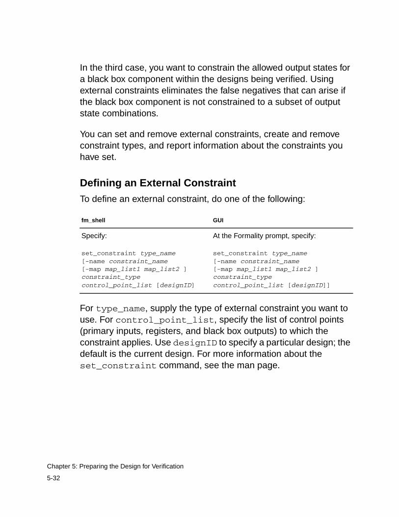
In the third case, you want to constrain the allowed output states fora black box component within the designs being verified. Usingexternal constraints eliminates the false negatives that can arise ifthe black box component is not constrained to a subset of outputstate combinations.
You can set and remove external constraints, create and removeconstraint types, and report information about the constraints youhave set.
Defining an External Constraint
To define an external constraint, do one of the following:
For type_name, supply the type of external constraint you want touse. For control_point_list, specify the list of control points(primary inputs, registers, and black box outputs) to which theconstraint applies. Use designID to specify a particular design; thedefault is the current design. For more information about theset_constraint command, see the man page.
fm_shell GUI
Specify:
set_constraint type_name[-name constraint_name[-map map_list1 map_list2 ]constraint_typecontrol_point_list [designID]
At the Formality prompt, specify:
set_constraint type_name[-name constraint_name[-map map_list1 map_list2 ]constraint_typecontrol_point_list [designID]]
5-32
Chapter 5: Preparing the Design for Verification
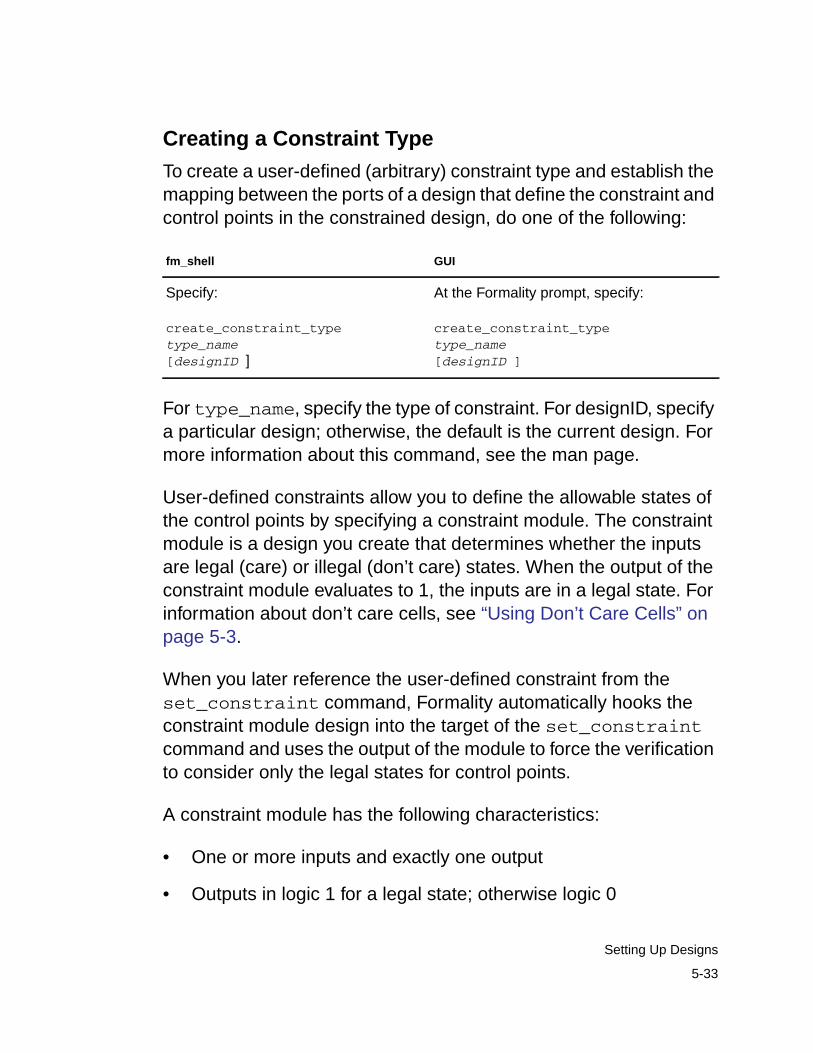
Creating a Constraint Type
To create a user-defined (arbitrary) constraint type and establish themapping between the ports of a design that define the constraint andcontrol points in the constrained design, do one of the following:
For type_name, specify the type of constraint. For designID, specifya particular design; otherwise, the default is the current design. Formore information about this command, see the man page.
User-defined constraints allow you to define the allowable states ofthe control points by specifying a constraint module. The constraintmodule is a design you create that determines whether the inputsare legal (care) or illegal (don’t care) states. When the output of theconstraint module evaluates to 1, the inputs are in a legal state. Forinformation about don’t care cells, see “Using Don’t Care Cells” onpage 5-3.
When you later reference the user-defined constraint from theset_constraint command, Formality automatically hooks theconstraint module design into the target of the set_constraintcommand and uses the output of the module to force the verificationto consider only the legal states for control points.
A constraint module has the following characteristics:
• One or more inputs and exactly one output
• Outputs in logic 1 for a legal state; otherwise logic 0
fm_shell GUI
Specify:
create_constraint_typetype_name[designID ]
At the Formality prompt, specify:
create_constraint_typetype_name[designID ]
5-33
Setting Up Designs
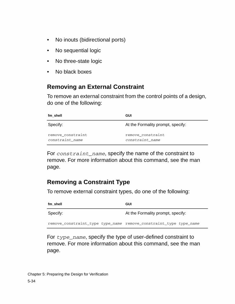
• No inouts (bidirectional ports)
• No sequential logic
• No three-state logic
• No black boxes
Removing an External Constraint
To remove an external constraint from the control points of a design,do one of the following:
For constraint_name, specify the name of the constraint toremove. For more information about this command, see the manpage.
Removing a Constraint Type
To remove external constraint types, do one of the following:
For type_name, specify the type of user-defined constraint toremove. For more information about this command, see the manpage.
fm_shell GUI
Specify:
remove_constraintconstraint_name
At the Formality prompt, specify:
remove_constraintconstraint_name
fm_shell GUI
Specify:
remove_constraint_type type_name
At the Formality prompt, specify:
remove_constraint_type type_name
5-34
Chapter 5: Preparing the Design for Verification
Reporting Constraint Information
To report information about the constraints set in your design, do oneof the following:
For constraint_name, specify the name of the constraint forwhich you want to obtain a report. For more information about thiscommand, see the man page.
Reporting Information About Constraint Types
To report information about constraint types set in your design, doone of the following:
For more information about report_constraint_typecommand, see the man page.
Working With Hierarchical Designs
You can control the following features of hierarchical designverification: the separator character used to create flattened pathnames, the operating mode for propagating constants throughout
fm_shell GUI
Specify:
report_constraint[-long ] constraint_name
At the Formality prompt, specify:
report_constraint[-long ] constraint_name
fm_shell GUI
Specify:
report_constraint_type[-long ] type_name
At the Formality prompt, specify:
report_constraint_type[-long ] type_name
5-35
Setting Up Designs
hierarchical levels, and whether or not Formality disregardshierarchical boundaries. The following sections describe thesefeatures.
Setting the Flattened Hierarchy Separator Character
Formality uses hierarchical information to simplify the verificationprocess, but it verifies designs in a flat context. By default, Formalityuses the slash (/) character as the separator in flattened design pathnames. If this separator character is not consistent with your namingscheme, you can change it.
To establish a character as the flattened path name separator, doone of the following:
The name_match_flattened_hierarchy_separator_stylevariable reads in the design hierarchy, and the character separatorallows Formality to understand where the hierarchical boundariesare. For more information about this variable, see the man page.
fm_shell GUI
Specify:
set name_match_flattened_hierarchy_separator_stylecharacter
1. Choose Edit > Formality Tcl Variables orthe Modify Formality Tcl Variables toolbaroption.
The Formality Tcl Variable Editor dialog boxappears.
2. From Matching, select thename_match_flattened_hierarchy_separator_style variable.
3. In the “Enter a single character” box,enter the character separator used in pathnames when designs are flattened andpress Enter.
4. Choose File > Close.
5-36
Chapter 5: Preparing the Design for Verification
Propagating Constants
When Formality verifies a design that contains hierarchy, the defaultbehavior is to propagate all constants throughout the hierarchy. Fora description of constant types as they apply to Formality, see“Working With Constants” on page 5-22.
In some cases, you might not want to propagate all constants duringhierarchical verification. To determine how Formality propagatesconstants, do one of the following:
You can use the verification_constant_prop_mode variableto specify where Formality is to start propagation during verification.In auto mode, the default, Formality traverses up the reference andimplementation hierarchy in lock step to automatically identify the topdesign from which to propagate constants. Therefore,correspondence between the hierarchy of the two designs affectsthis mode. Specify top to tell Formality to propagate from the designyou set as top with the set_top command. Specify target toinstruct Formality to propagate constants from the currently setreference and implementation designs.
Note:Setverification_constant_prop_mode totop ortargetonly if your reference and implementation designs do not havematching hierarchy. Setting the mode to auto when you havedifferent levels of hierarchy can cause Formality to propagatefrom an incorrect top-level design.
fm_shell GUI
Specify:
setverification_constant_prop_modemode
At the Formality prompt, specify:
setverification_constant_prop_modemode
5-37
Setting Up Designs
For more information about this variable, see the man page.
Working With Combinational Design Changes
This section describes how to prepare designs that have undergonea combinational transformation. Special attention is required if yourdesign contains combinational design changes, such as
• Internal scan insertions
• Boundary-scan insertions
• Clock tree buffers
Your design can also include sequential transformations. For moreinformation, see “Working With Sequential Design Changes” onpage 5-42.
Disabling Scan Logic
Internal scan insertion is a technique used to make it easier to setand observe the state of registers internal to a design. During scaninsertion, scan flops replace flip-flops. The scan flops are thenconnected into a long shift register. The additional logic added duringscan insertion means that the combinational function has changed,as shown in Figure 5-5.
5-38
Chapter 5: Preparing the Design for Verification
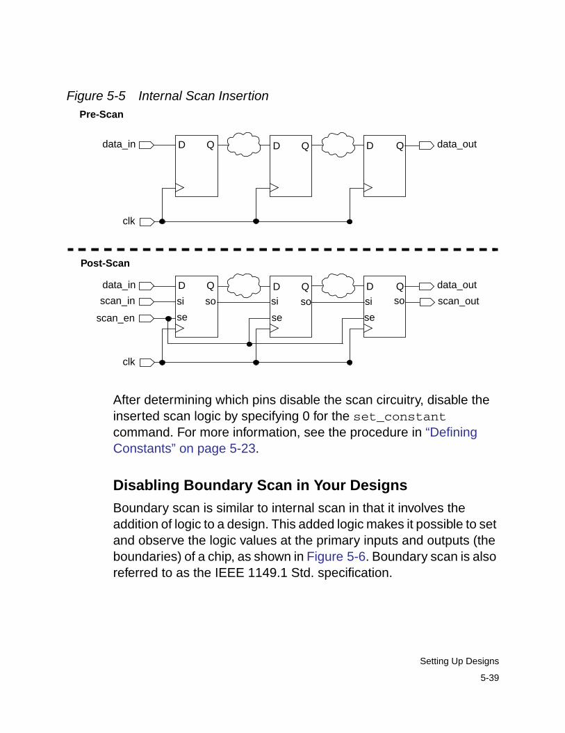
Figure 5-5 Internal Scan Insertion
After determining which pins disable the scan circuitry, disable theinserted scan logic by specifying 0 for the set_constantcommand. For more information, see the procedure in “DefiningConstants” on page 5-23.
Disabling Boundary Scan in Your Designs
Boundary scan is similar to internal scan in that it involves theaddition of logic to a design. This added logic makes it possible to setand observe the logic values at the primary inputs and outputs (theboundaries) of a chip, as shown in Figure 5-6. Boundary scan is alsoreferred to as the IEEE 1149.1 Std. specification.
data_in
clk
DD D QQ Q data_out
data_in
clk
DD D QQ Q data_out
scan_in
scan_en
scan_outsi
se
sosi siso so
se se
Pre-Scan
Post-Scan
5-39
Setting Up Designs
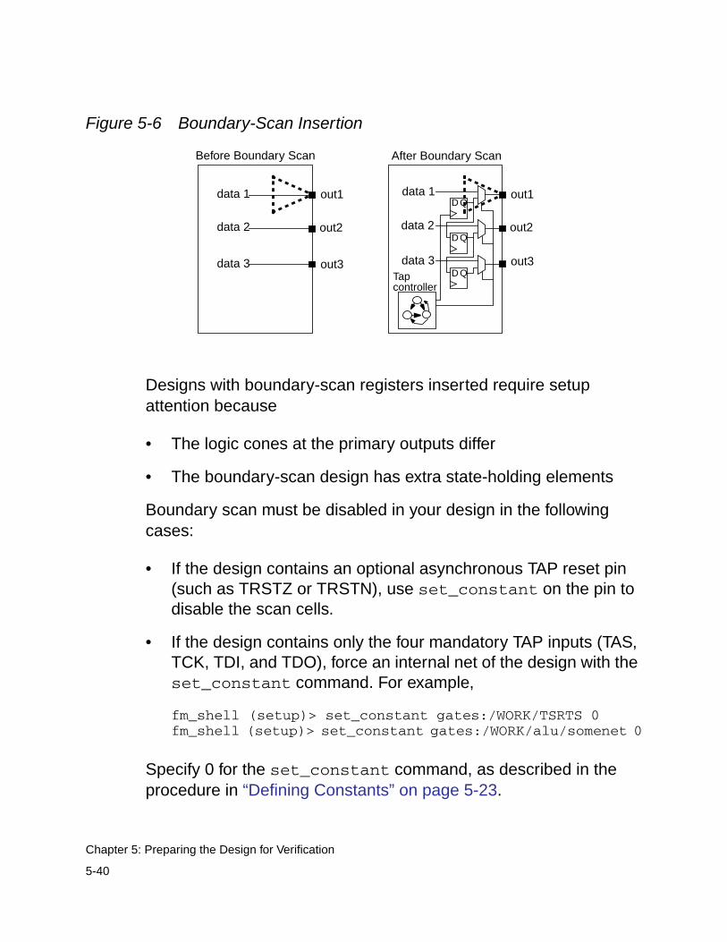
Figure 5-6 Boundary-Scan Insertion
Designs with boundary-scan registers inserted require setupattention because
• The logic cones at the primary outputs differ
• The boundary-scan design has extra state-holding elements
Boundary scan must be disabled in your design in the followingcases:
• If the design contains an optional asynchronous TAP reset pin(such as TRSTZ or TRSTN), use set_constant on the pin todisable the scan cells.
• If the design contains only the four mandatory TAP inputs (TAS,TCK, TDI, and TDO), force an internal net of the design with theset_constant command. For example,
fm_shell (setup)> set_constant gates:/WORK/TSRTS 0fm_shell (setup)> set_constant gates:/WORK/alu/somenet 0
Specify 0 for the set_constant command, as described in theprocedure in “Defining Constants” on page 5-23.
data 1
data 2
data 3
out1
out2
out3
data 1
data 2
data 3
out1
out2
out3Tapcontroller
Before Boundary Scan After Boundary Scan
D Q
D Q
D Q
5-40
Chapter 5: Preparing the Design for Verification
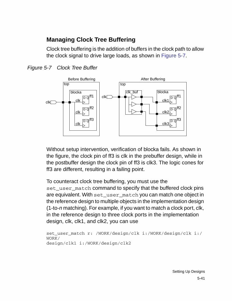
Managing Clock Tree Buffering
Clock tree buffering is the addition of buffers in the clock path to allowthe clock signal to drive large loads, as shown in Figure 5-7.
Figure 5-7 Clock Tree Buffer
Without setup intervention, verification of blocka fails. As shown inthe figure, the clock pin of ff3 is clk in the prebuffer design, while inthe postbuffer design the clock pin of ff3 is clk3. The logic cones forff3 are different, resulting in a failing point.
To counteract clock tree buffering, you must use theset_user_match command to specify that the buffered clock pinsare equivalent. With set_user_match you can match one object inthe reference design to multiple objects in the implementation design(1-to-n matching). For example, if you want to match a clock port, clk,in the reference design to three clock ports in the implementationdesign, clk, clk1, and clk2, you can use
set_user_match r: /WORK/design/clk i:/WORK/design/clk i:/WORK/design/clk1 i:/WORK/design/clk2
clk
clk
clk
clk
ff1
ff2
ff3
QD
QD
QD
blocka
topBefore Buffering After Buffering
clk1
clk3
clk2
ff1
ff2
ff3
QD
QD
QD
blockaclk
clk_buf
top
5-41
Setting Up Designs
Alternatively, you can issue multiple commands for each port in theimplementation:
set_user_match r: /WORK/design/clk i:/WORK/design/clkset_user_match r: /WORK/design/clk i:/WORK/design/clk1set_user_match r: /WORK/design/clk i:/WORK/design/clk2
If you know a clock port is inverted, use the -inverted option to theset_user_match command. Therefore, if your reference designhad a clock port, clk, and your implementation design had a clk portand an inverted clock port, clk_inv, you would use the followingcommand:
set_user_match r:/WORK/design/clk i:/WORK/design/clkset_user_match -inverted r:/WORK/design/clk i:/WORK/design/clk_inv
For more information about the set_user_match command, seethe man page.
Working With Sequential Design Changes
Like the combinational design changes described in “Working WithCombinational Design Changes” on page 5-38, sequential designchanges also require setup prior to verification. Sequential designchanges include:
• Adding asynchronous bypass circuitry to registers
• Clock gating
• Pushing inversions across registers
5-42
Chapter 5: Preparing the Design for Verification
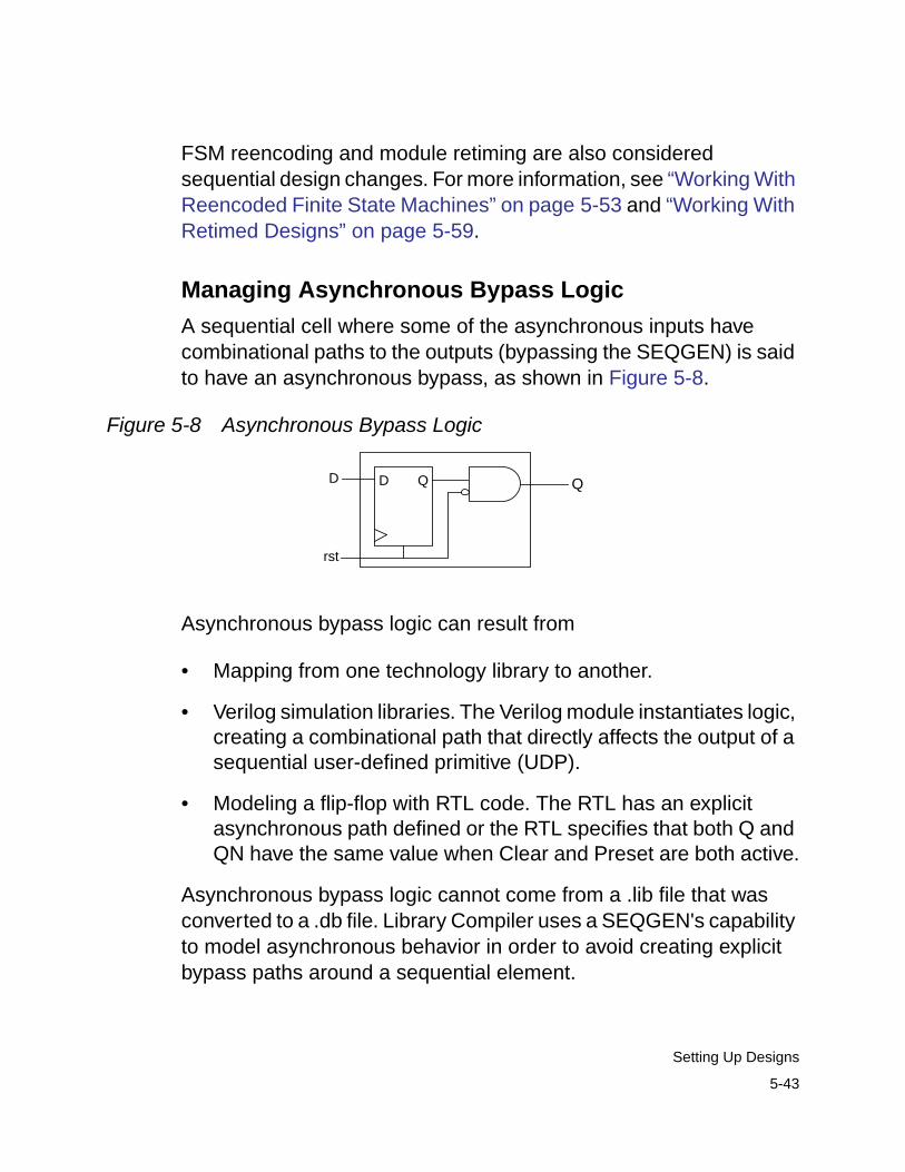
FSM reencoding and module retiming are also consideredsequential design changes. For more information, see “Working WithReencoded Finite State Machines” on page 5-53 and “Working WithRetimed Designs” on page 5-59.
Managing Asynchronous Bypass Logic
A sequential cell where some of the asynchronous inputs havecombinational paths to the outputs (bypassing the SEQGEN) is saidto have an asynchronous bypass, as shown in Figure 5-8.
Figure 5-8 Asynchronous Bypass Logic
Asynchronous bypass logic can result from
• Mapping from one technology library to another.
• Verilog simulation libraries. The Verilog module instantiates logic,creating a combinational path that directly affects the output of asequential user-defined primitive (UDP).
• Modeling a flip-flop with RTL code. The RTL has an explicitasynchronous path defined or the RTL specifies that both Q andQN have the same value when Clear and Preset are both active.
Asynchronous bypass logic cannot come from a .lib file that wasconverted to a .db file. Library Compiler uses a SEQGEN's capabilityto model asynchronous behavior in order to avoid creating explicitbypass paths around a sequential element.
D Q Q
rst
D
5-43
Setting Up Designs
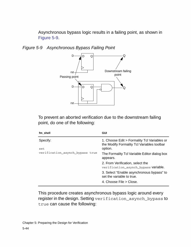
Asynchronous bypass logic results in a failing point, as shown inFigure 5-9.
Figure 5-9 Asynchronous Bypass Failing Point
To prevent an aborted verification due to the downstream failingpoint, do one of the following:
This procedure creates asynchronous bypass logic around everyregister in the design. Setting verification_asynch_bypass totrue can cause the following:
fm_shell GUI
Specify:
setverification_asynch_bypass true
1. Choose Edit > Formality Tcl Variables orthe Modify Formality Tcl Variables toolbaroption.
The Formality Tcl Variable Editor dialog boxappears.
2. From Verification, select theverification_asynch_bypass variable.
3. Select “Enable asynchronous bypass” toset the variable to true.
4. Choose File > Close.
D Q Q
rst
D
D Q Q
rst
D
Downstream failingpoint
Passing point
5-44
Chapter 5: Preparing the Design for Verification
• Longer verification runtimes
• Introduction of loops into the design
• Aborted verification due to design complexity
Asynchronous bypass affects the entire design and cannot beplaced on a single instance. In addition, asynchronous bypass isautomatically enabled when you verify cells in a technology library;because of the relative simplicity of library cells, no negative effectsoccur.
Setting Clock Gating
Clock gating can be used to implement load enable signals insynchronous registers. It results in more power-efficient circuits thanmultiplexer-based solutions. In its simplest form, clock gating is theaddition of logic in a register's clock path that disables the clock whenthe register output is not changing, as shown in Figure 5-10. You useclock gating to save power by not clocking register cellsunnecessarily.
5-45
Setting Up Designs
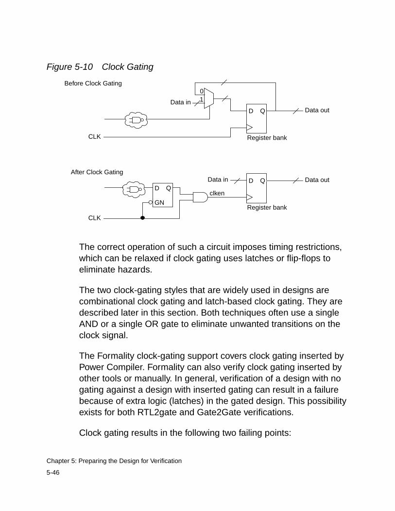
Figure 5-10 Clock Gating
The correct operation of such a circuit imposes timing restrictions,which can be relaxed if clock gating uses latches or flip-flops toeliminate hazards.
The two clock-gating styles that are widely used in designs arecombinational clock gating and latch-based clock gating. They aredescribed later in this section. Both techniques often use a singleAND or a single OR gate to eliminate unwanted transitions on theclock signal.
The Formality clock-gating support covers clock gating inserted byPower Compiler. Formality can also verify clock gating inserted byother tools or manually. In general, verification of a design with nogating against a design with inserted gating can result in a failurebecause of extra logic (latches) in the gated design. This possibilityexists for both RTL2gate and Gate2Gate verifications.
Clock gating results in the following two failing points:
D Q Data outData in
01
CLK Register bank
Before Clock Gating
D Q Data out
CLK
Register bank
D Qclken
Data in
GN
After Clock Gating
5-46
Chapter 5: Preparing the Design for Verification
• A compare point is created for the clock-gating latch. Thiscompare point does not have a matching point in the otherdesign, causing it to fail.
• The logic that feeds the clock input of the register bank changes.Thus, the compare points created at the register bank fail.
To instruct Formality to account for clock-gating logic, do one of thefollowing:
The verification_clock_gate_hold_mode variable can havethe following values:
• none (off) is the default.
• low allows clock gating that holds the clock low when inactive.
• high allows clock gating that holds the clock high when inactive.
• any allows both high and low styles of clock gating to beconsidered within the same design.
fm_shell GUI
Specify:
setverification_clock_gate_hold_mode[none | low | high | any |collapse_all_cg_cells ]
1. Choose Edit > Formality Tcl Variables orthe Formality Tcl Variables toolbar option.
The Formality Tcl Variable Editor dialog boxappears.
2. From Verification, select theverification_clock_gate_hold_modevariable.
3. From the “Choose a value” drop down,select the desired level from the menu.
4. Choose File > Close.
5-47
Setting Up Designs
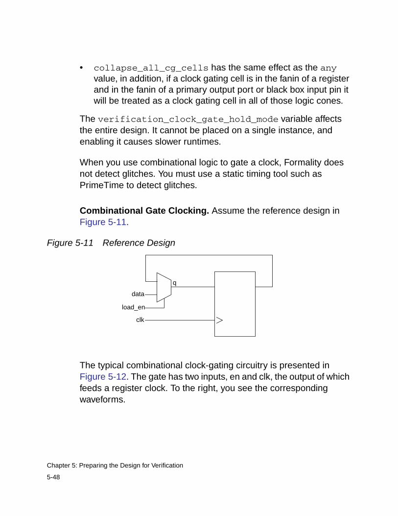
• collapse_all_cg_cells has the same effect as the anyvalue, in addition, if a clock gating cell is in the fanin of a registerand in the fanin of a primary output port or black box input pin itwill be treated as a clock gating cell in all of those logic cones.
The verification_clock_gate_hold_mode variable affectsthe entire design. It cannot be placed on a single instance, andenabling it causes slower runtimes.
When you use combinational logic to gate a clock, Formality doesnot detect glitches. You must use a static timing tool such asPrimeTime to detect glitches.
Combinational Gate Clocking. Assume the reference design inFigure 5-11.
Figure 5-11 Reference Design
The typical combinational clock-gating circuitry is presented inFigure 5-12. The gate has two inputs, en and clk, the output of whichfeeds a register clock. To the right, you see the correspondingwaveforms.
q
data
load_en
clk
5-48
Chapter 5: Preparing the Design for Verification
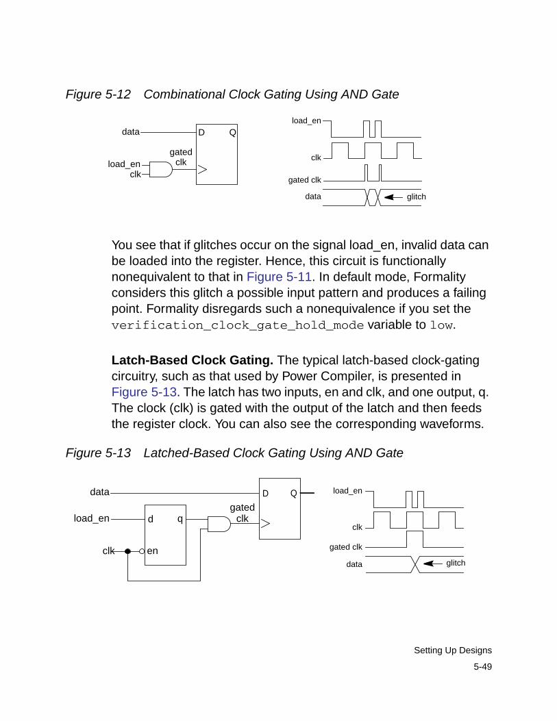
Figure 5-12 Combinational Clock Gating Using AND Gate
You see that if glitches occur on the signal load_en, invalid data canbe loaded into the register. Hence, this circuit is functionallynonequivalent to that in Figure 5-11. In default mode, Formalityconsiders this glitch a possible input pattern and produces a failingpoint. Formality disregards such a nonequivalence if you set theverification_clock_gate_hold_mode variable to low.
Latch-Based Clock Gating. The typical latch-based clock-gatingcircuitry, such as that used by Power Compiler, is presented inFigure 5-13. The latch has two inputs, en and clk, and one output, q.The clock (clk) is gated with the output of the latch and then feedsthe register clock. You can also see the corresponding waveforms.
Figure 5-13 Latched-Based Clock Gating Using AND Gate
D Qdata
clk
gatedclkload_en
load_en
clk
gated clk
data glitch
clk
D Q
load_en d q
en
data
gatedclk
clk
load_en
gated clk
data glitch
5-49
Setting Up Designs
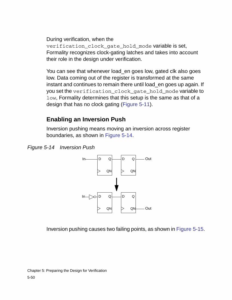
During verification, when theverification_clock_gate_hold_mode variable is set,Formality recognizes clock-gating latches and takes into accounttheir role in the design under verification.
You can see that whenever load_en goes low, gated clk also goeslow. Data coming out of the register is transformed at the sameinstant and continues to remain there until load_en goes up again. Ifyou set the verification_clock_gate_hold_mode variable tolow, Formality determines that this setup is the same as that of adesign that has no clock gating (Figure 5-11).
Enabling an Inversion Push
Inversion pushing means moving an inversion across registerboundaries, as shown in Figure 5-14.
Figure 5-14 Inversion Push
Inversion pushing causes two failing points, as shown in Figure 5-15.
D Q D Q
QNQN
In Out
D Q D Q
QNQN
In
Out
5-50
Chapter 5: Preparing the Design for Verification
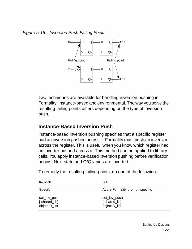
Figure 5-15 Inversion Push Failing Points
Two techniques are available for handling inversion pushing inFormality: instance-based and environmental. The way you solve theresulting failing points differs depending on the type of inversionpush.
Instance-Based Inversion Push
Instance-based inversion pushing specifies that a specific registerhad an inversion pushed across it. Formality must push an inversionacross the register. This is useful when you know which register hadan inverter pushed across it. This method can be applied to librarycells. You apply instance-based inversion pushing before verificationbegins. Next state and Q/QN pins are inverted.
To remedy the resulting failing points, do one of the following:
fm_shell GUI
Specify:
set_inv_push[-shared_lib]objectID_list
At the Formality prompt, specify:
set_inv_push[-shared_lib]objectID_list
D Q D Q
QNQN
In Out
D Q D Q
QNQN
In
Out
Failing pointFailing point
5-51
Setting Up Designs
For example,
fm_shell (setup)> set_inv_push ref:/WORK/alu/z_reg
To indicate an inversion push, you might prefer to use theset_user_match command with the -inverted or-noninverted option. This command with either option handlesinverted polarity. Polarity conflicts between set_inv_push andset_user_match applied to the same point are resolved by usingthe polarity specified by set_user_match.
For more information about the set_inv_push andset_user_match commands, see their respective man pages.
Environmental Inversion Push
Each compare point matched pair has a compare polarity that iseither inverted or noninverted. Inverted polarities can occur due tothe style of vendor libraries, design optimizations by synthesis, ormanually generated designs. If environmental inversion pushing isnot enabled, Formality matches all compare points with anoninverted compare polarity unless you specify otherwise by usingset_user_match -inverted.
Environmental inversion pushing allows Formality to match all statepoints automatically with the correct polarity during matching.Environmental inversion pushing is off by default. Enable it only afteryou resolve all setup issues and ensure that differences in thedesigns are due to inverted state points. If there are failing comparepoints and environmental inversion pushing is enabled, the tool canspend a long time attempting to find a set of inverted matches tosolve the verification, but this can be impossible because the
5-52
Chapter 5: Preparing the Design for Verification
compare points are not equivalent. Use this variable only if you knowan inversion push was used during creation of the implementationdesign.
Formality can automatically use environmental inversion pushing tomatch state points with the correct polarity. This is done in thefollowing way:
In the GUI, compare polarity is indicated by “+” for noninverted, “-” forinverted, and “?” for unspecified. In addition, match-related reportsnow have a column to indicate polarity. The “-” indicates invertedpolarity, a space, “ ”, indicates noninverted polarity. For user matchreports a “?” indicates unspecified polarity.
Working With Reencoded Finite State Machines
The architecture for a finite state machine (FSM) consists of a set offlip-flops for holding the state vector and a combinational logicnetwork that produces the next state vector and the output vector.For more information about FSMs, see the Design Compilerdocumentation.
fm_shell GUI
Specify:
set verification_inversion_pushtrue
1. Choose Edit > Formality Tcl Variables orthe Modify Formality Tcl Variables toolbaroption.
The Formality Tcl Variable Editor dialog boxappears.
2. From Verification, select theverification_inversion_push variable.
3. Select “Enable inversion push”.
4. Choose File > Close.
5-53
Setting Up Designs
Before verifying a reencoded FSM in the implementation designagainst its counterpart in the reference design, you must take stepsthat allow Formality to make verification possible. These steps definethe FSM state vectors and establish state names with theirrespective encoding.
Without your intervention, Formality is unable to verify two FSMs thathave different encoding, even if they have the same sequence ofstates and output vectors.
Formality provides several methods to name flip-flops and defineencoding. User-defined encoding is not verified by Formality, so takecare to specify the encoding correctly. The easiest method is to usethe automated setup file generated by Design Compiler. You canalso use a single fm_shell command to read a user-supplied filethat contains all the information at once, or you can use twocommands to first name state vector flip-flops and then define thestate names and their encoding. These methods are described in thefollowing sections.
Using the Automated Setup File for FSM Reencoding
The automated setup file generated by Design Compiler containsFSM state vector encoding. This encoding is in the form ofguide_fsm_reencoding commands. Use the following variable totell Formality to use the FSM guidance in the Design Compilerautomated setup file:
set svf_ignore_unqualified_fsm_information false
5-54
Chapter 5: Preparing the Design for Verification
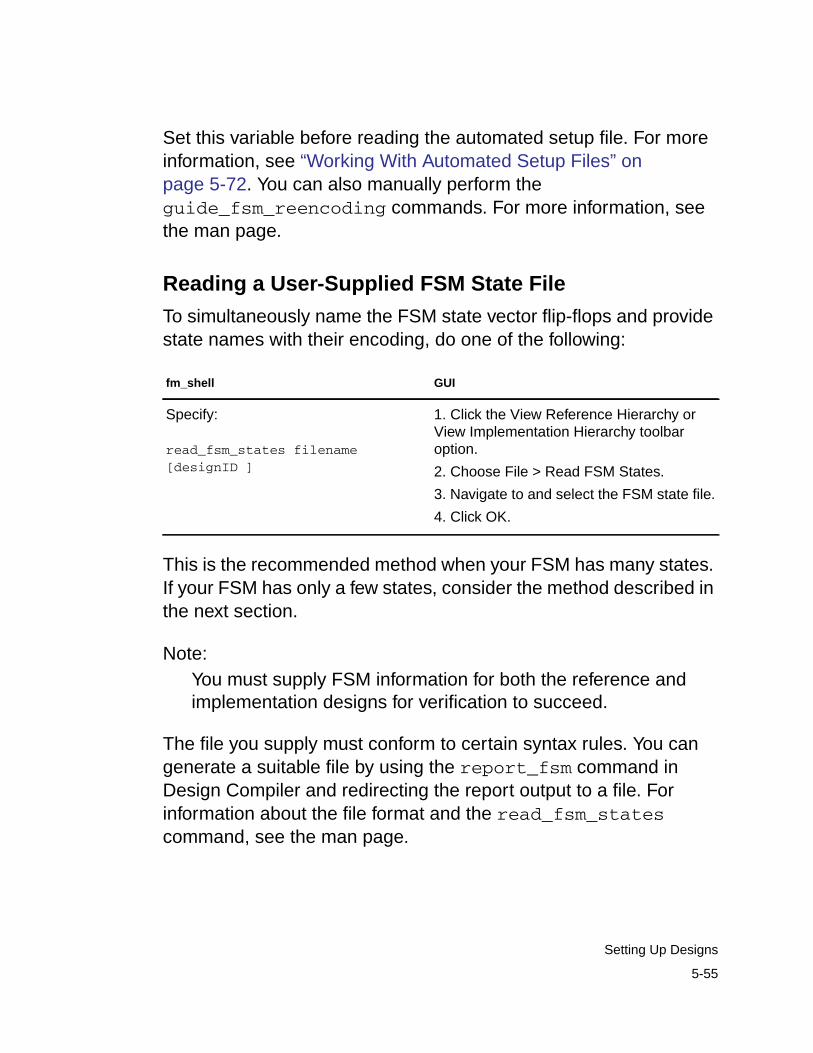
Set this variable before reading the automated setup file. For moreinformation, see “Working With Automated Setup Files” onpage 5-72. You can also manually perform theguide_fsm_reencoding commands. For more information, seethe man page.
Reading a User-Supplied FSM State File
To simultaneously name the FSM state vector flip-flops and providestate names with their encoding, do one of the following:
This is the recommended method when your FSM has many states.If your FSM has only a few states, consider the method described inthe next section.
Note:You must supply FSM information for both the reference andimplementation designs for verification to succeed.
The file you supply must conform to certain syntax rules. You cangenerate a suitable file by using the report_fsm command inDesign Compiler and redirecting the report output to a file. Forinformation about the file format and the read_fsm_statescommand, see the man page.
fm_shell GUI
Specify:
read_fsm_states filename[designID ]
1. Click the View Reference Hierarchy orView Implementation Hierarchy toolbaroption.
2. Choose File > Read FSM States.
3. Navigate to and select the FSM state file.
4. Click OK.
5-55
Setting Up Designs
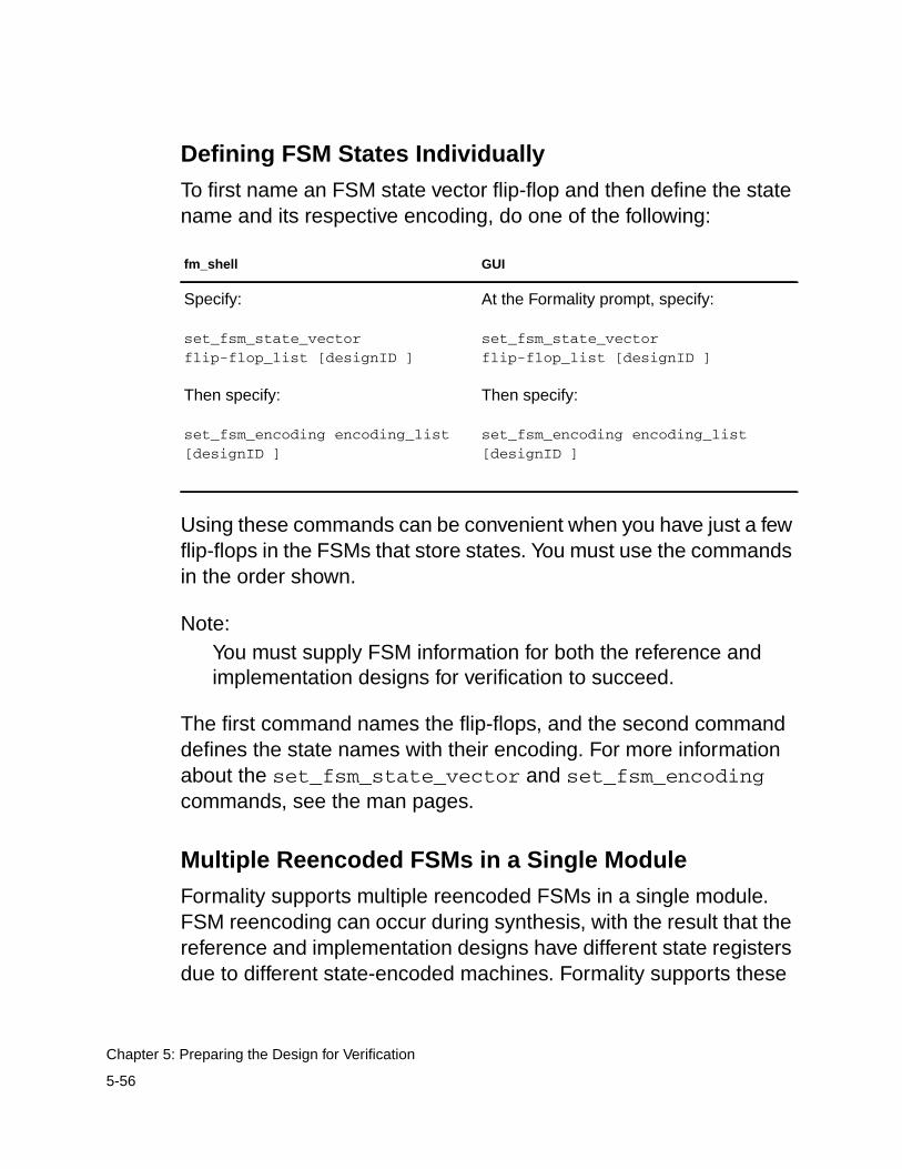
Defining FSM States Individually
To first name an FSM state vector flip-flop and then define the statename and its respective encoding, do one of the following:
Using these commands can be convenient when you have just a fewflip-flops in the FSMs that store states. You must use the commandsin the order shown.
Note:You must supply FSM information for both the reference andimplementation designs for verification to succeed.
The first command names the flip-flops, and the second commanddefines the state names with their encoding. For more informationabout the set_fsm_state_vector and set_fsm_encodingcommands, see the man pages.
Multiple Reencoded FSMs in a Single Module
Formality supports multiple reencoded FSMs in a single module.FSM reencoding can occur during synthesis, with the result that thereference and implementation designs have different state registersdue to different state-encoded machines. Formality supports these
fm_shell GUI
Specify:
set_fsm_state_vectorflip-flop_list [designID ]
Then specify:
set_fsm_encoding encoding_list[designID ]
At the Formality prompt, specify:
set_fsm_state_vectorflip-flop_list [designID ]
Then specify:
set_fsm_encoding encoding_list[designID ]
5-56
Chapter 5: Preparing the Design for Verification
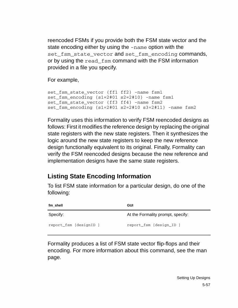
reencoded FSMs if you provide both the FSM state vector and thestate encoding either by using the -name option with theset_fsm_state_vector and set_fsm_encoding commands,or by using the read_fsm command with the FSM informationprovided in a file you specify.
For example,
set_fsm_state_vector {ff1 ff2} -name fsm1set_fsm_encoding {s1=2#01 s2=2#10} -name fsm1set_fsm_state_vector {ff3 ff4} -name fsm2set_fsm_encoding {s1=2#01 s2=2#10 s3=2#11} -name fsm2
Formality uses this information to verify FSM reencoded designs asfollows: First it modifies the reference design by replacing the originalstate registers with the new state registers. Then it synthesizes thelogic around the new state registers to keep the new referencedesign functionally equivalent to its original. Finally, Formality canverify the FSM reencoded designs because the new reference andimplementation designs have the same state registers.
Listing State Encoding Information
To list FSM state information for a particular design, do one of thefollowing:
Formality produces a list of FSM state vector flip-flops and theirencoding. For more information about this command, see the manpage.
fm_shell GUI
Specify:
report_fsm [designID ]
At the Formality prompt, specify:
report_fsm [design_ID ]
5-57
Setting Up Designs
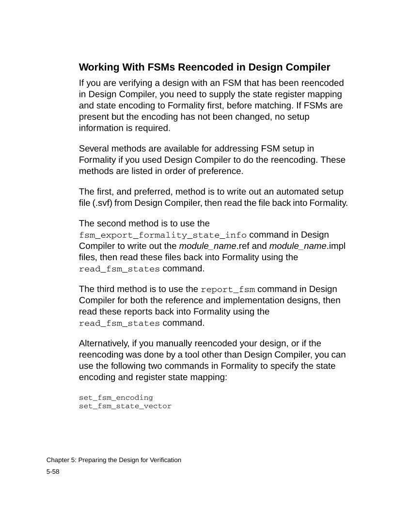
Working With FSMs Reencoded in Design Compiler
If you are verifying a design with an FSM that has been reencodedin Design Compiler, you need to supply the state register mappingand state encoding to Formality first, before matching. If FSMs arepresent but the encoding has not been changed, no setupinformation is required.
Several methods are available for addressing FSM setup inFormality if you used Design Compiler to do the reencoding. Thesemethods are listed in order of preference.
The first, and preferred, method is to write out an automated setupfile (.svf) from Design Compiler, then read the file back into Formality.
The second method is to use thefsm_export_formality_state_info command in DesignCompiler to write out the module_name.ref and module_name.implfiles, then read these files back into Formality using theread_fsm_states command.
The third method is to use the report_fsm command in DesignCompiler for both the reference and implementation designs, thenread these reports back into Formality using theread_fsm_states command.
Alternatively, if you manually reencoded your design, or if thereencoding was done by a tool other than Design Compiler, you canuse the following two commands in Formality to specify the stateencoding and register state mapping:
set_fsm_encodingset_fsm_state_vector
5-58
Chapter 5: Preparing the Design for Verification
You must use these two commands for both the reference andimplementation designs.
Working With Retimed Designs
Retiming a design moves registers across combinational logic in aneffort to meet timing or area requirements. Retiming can occurduring synthesis or it can be a result of “hand editing” a design.Retiming can change the number of registers in a design and thelogic driving the registers.
If the implementation design has been retimed but the referencedesign has not been retimed, the register compare points becomeunmatchable. In this case, setup is required to prepare Formality tomatch and verify the design. If the design has been retimed using theoptimize_registers command in Design Compiler, you can usethe automated setup file in Formality. If the design has been retimedwith another method, you can set a parameter to instruct Formalityto take into account the design changes caused by retiming.
Retiming Using Design Compiler
When using the optimize_registers command in DesignCompiler, a set of retiming guidance commands is written into theautomated setup file. If you do not specify an automated setup filewith the set_svf command, a default file called default.svf isautomatically created.
The retiming guidance commands represent the logic through whichthe retimed registers have moved. When the svf_retimingvariable is enabled, Formality adds logic to both the reference andimplementation designs that represents the retiming moves.Additionally, Formality adds black boxes that create cutpoints that
5-59
Setting Up Designs
allow the designs to be properly matched for verification. Theadditional logic and black boxes enable Formality to verify both thevalidity of retiming and the equivalence of the designs.
The retiming guidance commands are as follows:
• guide_retiming
• guide_retiming_decompose
• guide_retiming_multibit
• guide_retiming_finished
To retime a design using Design Compiler, do the following:
1. From Design Compiler, use the set_svf command to indicatethe automated setup file where the retiming guidance commandsare written.
If the set_svf command is not used, a file named default.svf isautomatically created.
2. Read into Design Compiler the design you want retimed.
3. Apply the appropriate timing constraints and implement thecompile strategy.
4. Use the optimize_registers command to retime the design.
5. After optimization is complete, write out the retimed netlist.
Multiple optimize_registers commands can beaccommodated by writing out an additional netlist after eachcommand. After each netlist is written, you must issue a newset_svf command with a unique file name before running thenext optimize_registers command. The additional netlists
5-60
Chapter 5: Preparing the Design for Verification
and guide files can then be used in a multistep verificationmethodology (RTL versus netlist 1, netlist 1 versus netlist 2,netlist 2 versus netlist 3, and so on).
To verify a retimed design with Formality, do the following:
1. In Formality, enable the following variable:
fm_shell (setup)> set svf_retiming true
The svf_retiming variable controls whether Formalityprocesses all retiming guidance commands located in theuser-specified automated setup file. A value of true indicatesthat retiming guidance commands are accepted. A value offalse indicates that related retiming guidance commands areignored. The svf_retiming variable affects only the retimingguidance commands.
2. Use the set_svf command to tell Formality the location of theautomated setup file that contains the retiming guidancecommands.
fm_shell (setup)> set_name.svf
3. Read the design data into Formality.
Read the original design as the reference design and the retimednetlist as the implementation design.
4. Apply any additional setup requirements for the designs.
5. Perform a verification of the design.
5-61
Setting Up Designs
Retiming Using Other Tools
For designs that have been retimed outside of Design Compiler or forpipelined DesignWare parts, specify that the design has beenretimed by doing one of the following:
Note:The pipelined DesignWare parts, DW02_mult_n_stage andDW_pipe_mult, are detected and handled automatically byFormality. Therefore, you do not need to set the retimedparameter for these parts.
Working With Single-State Holding Elements
A level-sensitive scan design (LSSD) cell is a single-state holdingelement that consists of two latches arranged in a master-slaveconfiguration. LSSD cells occur frequently when you use IBMlibraries.
LSSD cells result in two compare points in the gate-level design, asshown in Figure 5-16. The RTL design contains a SEQGEN thatresults in one compare point. The dotted line separates thereference design from the implementation design.
fm_shell GUI
Specify:
set_parameters -retimed designID
1. Choose Setup > Design Parameters.
2. Click the Reference or Implementationtab.
3. Select a library and a design.
4. Select the “Design has been retimed”box.
5-62
Chapter 5: Preparing the Design for Verification
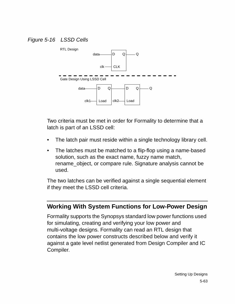
Figure 5-16 LSSD Cells
Two criteria must be met in order for Formality to determine that alatch is part of an LSSD cell:
• The latch pair must reside within a single technology library cell.
• The latches must be matched to a flip-flop using a name-basedsolution, such as the exact name, fuzzy name match,rename_object, or compare rule. Signature analysis cannot beused.
The two latches can be verified against a single sequential elementif they meet the LSSD cell criteria.
Working With System Functions for Low-Power Design
Formality supports the Synopsys standard low power functions usedfor simulating, creating and verifying your low power andmulti-voltage designs. Formality can read an RTL design thatcontains the low power constructs described below and verify itagainst a gate level netlist generated from Design Compiler and ICCompiler.
D Q D Qdata Q
Load Loadclk2clk1
D Qdata
CLKclk
QRTL Design
Gate Design Using LSSD Cell
5-63
Setting Up Designs
There are three constructs supported in both Verilog and VHDL.These are referred to by the Verilog system function call names:$isolate(), $power(), and $retain(). There are equivalent VHDLfunction calls in the snps_ext.power package provided with Formality(and Design Compiler). If you are using these constructs in yourdesign, Formality can be used to verify these designs.
Both $power() and $retain() specify hierarchical blocks and controlsignals for those blocks. Formality will add ports to the hierarchicalblocks in the design to propagate the required control signals intothose blocks. The function $isolate() is used add different types ofisolation cells between nets in the RTL. When the isolation functionappears in the RTL, Formality handles it automatically by insertingthe appropriate isolation cells into the design.
For more specific information on using these functions, refer to theDesign Compiler and Power Compiler documentation.
There are two ways designs synthesized using these constructs canbe verified:
1) Verify a netlist from Design Compiler.
Formality will verify the power up functionality of the netlist. In theblocks controlled by $power, Formality will not allow a failure at anycompare point in a block when that block is powered down in theRTL. As the netlist out of Design Compiler does not have power/ground connectivity, the gates will never power down. Thus,Formality is only verifying the power up behavior in this case.
2) Verify a netlist from IC Compiler.
5-64
Chapter 5: Preparing the Design for Verification
You must use IC Compiler to create a netlist that has the power andground nets connected to each cell. Formality can verify the powerup functionality (as in 1. above). In addition, if the gates power downunexpectedly, when compared with the RTL, there will be failingpoints.
If $retain is used in the RTL, Formality will substitute (in the specifiedblocks) retention registers for the normal registers inferred by theRTL. Formality will use the control signals specified in the $retainfunction to connect to the inserted retention registers to the save andrestore functionality. The netlist to be verified must have retentionregisters (consistent with clock-free RTL model) in the blocksspecified in the RTL or the verification will have failing points.
To support the verification of designs from IC Compiler using netliststhat contain power and ground connections to each cell, additionalsteps may be required to read and link the netlist. Formality willautomatically link the cells in the netlist to a library that does not havepower and ground pins specified in the technology library.
If there are two pins on the instances of cells with names that matchthe value of the Formality variables:
mw_logic0_net= "VSS" (for ground, which is set to logic 0)
mw_logic1_net= "VDD" (for power, which is set to logic 1)
For example, a Verilog netlist instance with power/ground pins mightlook like the following:
and2p1 U1(.A(state_3_0) , .B(state_4_0), .Z(dc42), .VDD(VDD), .VSS(VSS))
Formality can automatically link this instance to a cell that is declaredwithout the power and ground pins VDD and VSS.
5-65
Setting Up Designs
Some cells in the technology library may have multiple power pins -retention cells will typically have primary and secondary power andground pins; level shifters might also have multiple power andground pins. Formality cannot automatically link those cells to alibrary without additional power and ground pin information. Forthese cases, when reading the technology .db file containing thesecells with multiple power pins, use the read_db command with the-pg_pin switch.
read_db -pg_pin mytechlib.db
Formality will then look for pg_pin attribute information that is storedin the .db and generate the appropriate power and ground pins whenreading the technology library. This should allow you to read and linknetlists containing power and ground connections into Formality forverification.
Working with Retention Registers without RTL SystemFunctions for Low Power Design
Formality supports the verification of designs with retentionregisters. For information about retention registers, see the PowerCompiler User Guide. To verify a netlist with retention registersagainst RTL code without retention registers, you must disable allretention registers’ sleep mode. To disable their sleep mode, set aconstant on the sleep pins on the retention registers.
Formality reads design information describing retention registersfrom RTL, technology libraries, and implementation netlistsproduced by Power Compiler. During compare point matching,Formality checks retention registers in the reference design againstmatching registers in the implementation design for the
5-66
Chapter 5: Preparing the Design for Verification
power_gating_style attribute. Set theenable_power_gatingvariable to true to enable Formality to check retention registers. Thedefault is false.
You can define the power of the gating style by using theset_power_gating_style command. To apply different retentionregisters to different HDL blocks, use the commandset_power_gating_style-hdl_blocks block_label -type type_name. The-hdl_blocks option is required for this command. The value ofblock_label should match the Verilog name always blocks or VHDLprocesses. The type_name argument should name thepower_gating_cell attribute value.
To have Formality issue a retention register check report, use thereport_power_gating command. This report summarizesmatching register pairs without power-gating attributes, withcompatible power-gating attributes, and with incompatiblepower-gating attributes.
Working With Multiplier Architectures
Formality uses the arithmetic generator feature automatically toimprove the performance and ability to solve designs wheremultipliers have been flattened into gate-level netlists. Use of thearithmetic generator in Formality creates multipliers of a specific typeso that the synthesized representation of the reference RTL moreclosely matches the gate implementation. Therefore, assisting in theverification of difficult datapath problems.
The arithmetic generator can create the following multiplierarchitectures:
• Carry-save array (csa)
5-67
Setting Up Designs
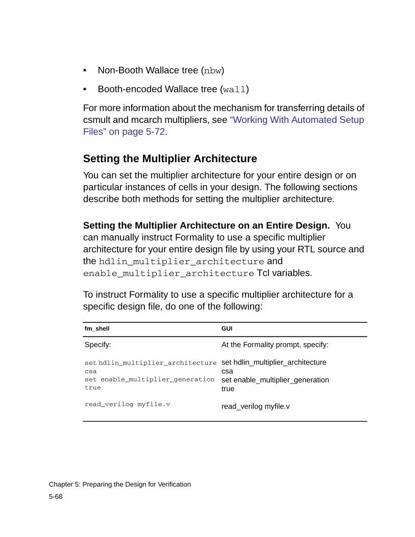
• Non-Booth Wallace tree (nbw)
• Booth-encoded Wallace tree (wall)
For more information about the mechanism for transferring details ofcsmult and mcarch multipliers, see “Working With Automated SetupFiles” on page 5-72.
Setting the Multiplier Architecture
You can set the multiplier architecture for your entire design or onparticular instances of cells in your design. The following sectionsdescribe both methods for setting the multiplier architecture.
Setting the Multiplier Architecture on an Entire Design. Youcan manually instruct Formality to use a specific multiplierarchitecture for your entire design file by using your RTL source andthe hdlin_multiplier_architecture andenable_multiplier_architecture Tcl variables.
To instruct Formality to use a specific multiplier architecture for aspecific design file, do one of the following:
fm_shell GUI
Specify:
set hdlin_multiplier_architecturecsaset enable_multiplier_generationtrue
read_verilog myfile.v
At the Formality prompt, specify:
set hdlin_multiplier_architecturecsaset enable_multiplier_generationtrue
read_verilog myfile.v
5-68
Chapter 5: Preparing the Design for Verification
The default value for hdlin_multiplier_architecture isnone. The arithmetic generator attempts to duplicate thearchitecture Design Compiler used in determining which architectureis appropriate. Formality uses the value defined in thedw_foundation_threshold Tcl variable to help select thearchitecture. If you do not want Formality to determine thearchitecture, set the value of thehdlin_multiplier_architecture variable to your preferredarchitecture.
For more information about thehdlin_multiplier_architecture anddw_foundation_threshold variables, see the man pages.
Note:You also have the choice of setting the multiplier architecture byusing the architecture_selection_precedence Tclvariable. With this variable you can define which mechanismtakes precedence.
Setting the Multiplier Architecture on a Specific Cell Instance.
You can replace the architecture for a specific multiplier ObjectID.While you are in setup mode and after elaboration, use theenable_multiplier_generation variable and theset_architecture command with the specific cell ObjectID andspecific architecture to set the desired multiplier architecture.
5-69
Setting Up Designs
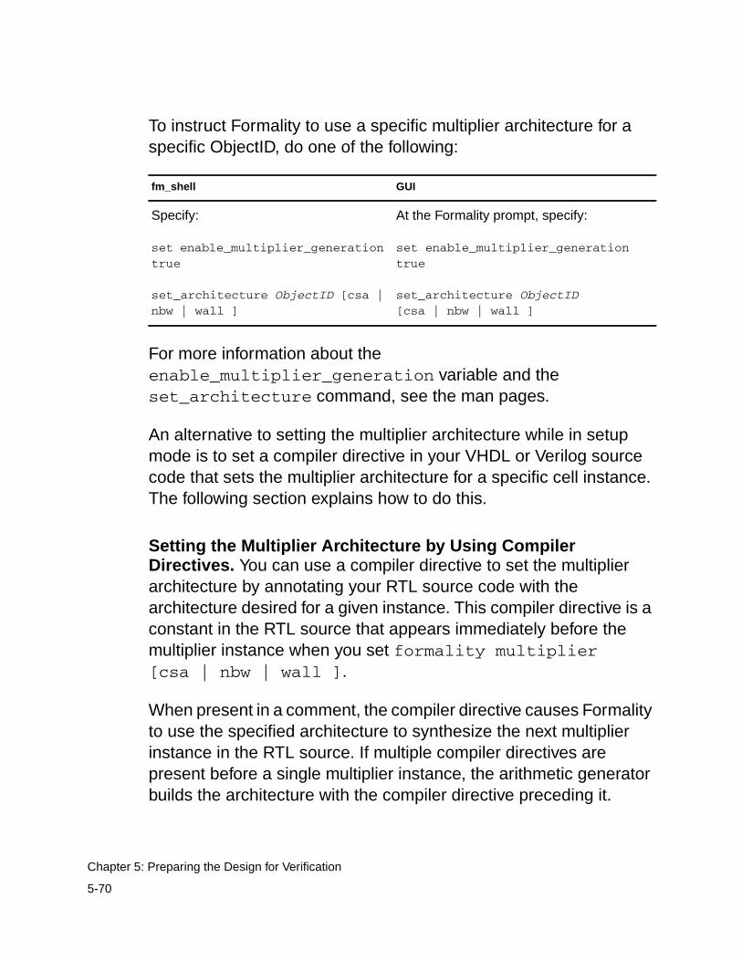
To instruct Formality to use a specific multiplier architecture for aspecific ObjectID, do one of the following:
For more information about theenable_multiplier_generation variable and theset_architecture command, see the man pages.
An alternative to setting the multiplier architecture while in setupmode is to set a compiler directive in your VHDL or Verilog sourcecode that sets the multiplier architecture for a specific cell instance.The following section explains how to do this.
Setting the Multiplier Architecture by Using CompilerDirectives. You can use a compiler directive to set the multiplierarchitecture by annotating your RTL source code with thearchitecture desired for a given instance. This compiler directive is aconstant in the RTL source that appears immediately before themultiplier instance when you set formality multiplier[csa | nbw | wall ].
When present in a comment, the compiler directive causes Formalityto use the specified architecture to synthesize the next multiplierinstance in the RTL source. If multiple compiler directives arepresent before a single multiplier instance, the arithmetic generatorbuilds the architecture with the compiler directive preceding it.
fm_shell GUI
Specify:
set enable_multiplier_generationtrue
set_architecture ObjectID [csa |nbw | wall ]
At the Formality prompt, specify:
set enable_multiplier_generationtrue
set_architecture ObjectID[csa | nbw | wall ]
5-70
Chapter 5: Preparing the Design for Verification
The compiler directive can be in Verilog or VHDL source. Thefollowing shows an example of each:
Verilog
// formality multiplier nbwz <= a*b;
VHDL
-- formality multiplier nbwz <= a*b;
In both instances, this compiler directive informs the arithmeticgenerator to use a non-Booth Wallace tree architecture (nbw) for the“a * b” multiplier instance.
Reporting Your Multiplier Architecture
To report the architecture used to implement a certain ObjectID, aswell as what caused that ObjectID to be selected, you can use thereport_architecture command.
To instruct Formality to report on the multiplier architecture used inyour design, do one of the following:
For more information about the report_architecturecommand and its options, see the man page.
fm_shell GUI
Specify:
report_architecture -all
At the Formality prompt, specify:
report_architecture -all
5-71
Setting Up Designs
Working With Automated Setup Files
The benefit of an automated setup file (.svf) is that it allows theimplementation tool to automatically provide setup information toFormality. It helps Formality understand and process designchanges caused by other tools that were used in the design flow.Formality uses this information to assist compare point matching andcorrectly set up verification without your intervention. It eliminatesthe need to enter setup information manually, a task that is timeconsuming and error prone. For example, during synthesis thephase of a register might be inverted. This change is recorded in theautomated setup file (.svf). When you read the automated setup fileinto Formality, the tool can account for the phase inversion duringcompare point matching and verification.
The first step in the automated setup flow is to create the automatedsetup file during synthesis. Both Design Compiler and Presto recorddata in the automated setup file that Formality can use. Next, youinstruct Formality to read this file at the start of the verificationprocess.
Creating an Automated Setup File
You would usually obtain an automated setup file from other tools,such as Design Compiler. In Design Compiler, you can write out anautomated setup file that describes the design changes. DesignCompiler automatically creates an automated setup file calleddefault.svf during a synthesis session.
To change the name of the file, use the set_svf Design Compilercommand as follows:
dc_shell> set_svf myfile.svf
5-72
Chapter 5: Preparing the Design for Verification
When Presto or Design Compiler performs an optimization thatFormality needs to know about, the relevant Formality guidancecommands are added to the automated setup file (.svf). If youchoose to use the set_svf command to specify the name of theautomated setup file, you must do this before optimization takesplace. Otherwise, those optimizations are not written to the userspecified automated setup file. Design Compiler may also create adirectory named dwsvf_processID, where processID is the processID. This directory is referenced by the automated setup file. Itcontains information about datapath optimizations performed byDesign Compiler.
To append the setup information to an existing automated setup file,use the following syntax:
dc_shell> set_svf -append myfile2.svf
You can use the -append argument if you compile a design usingmultiple invocations of Design Compiler. You may want to keep all thesetup information in a single file rather than using a separateautomated setup file for each Design Compiler invocation.
Reading an Automated Setup File Into Formality
To read an automated setup file into Formality, use the set_svfcommand. You must read in the automated setup file (.svf) beforeyou read in any design data. Formality uses the information in thesetup file during matching as well as verification. Formalityautomatically converts these binary files into text. It creates adirectory named formality_svf which will contain a text file namedsvf.txt representing all automated setup files read in and also anysub-directories for any automated setup file netlists encountered.
The following example reads in the automated setup file, myfile.svf.
5-73
Setting Up Designs
fm_shell> set_svf myfile.svfSVF set to '/home/my/designs/myfile.svf'.1fm_shell>
The set_svf command returns 1 if the command succeeds or 0 ifthe command fails. If you use set_svf without specifying theautomated setup file (.svf) to use, Formality resets the automatedsetup file. However, the appropriate method for removing the storedsetup data is to use the remove_guidance command.
Note:You can also invoke the set_svf command from the Guidancetab in the GUI.
Reading In Multiple Automated Setup Files
The commands in the automated setup files describetransformations in an incremental way. The transformations occur inthe order in which the commands were applied as the RTL designwas processed through design implementation or optimization.Therefore, the ability to read in multiple automated setup files isimportant because no command in the file can be viewed completelyindependently. It describes the incremental transformation and relieson the context in which it is applied.
You can read multiple automated setup files into Formality using theset_svf command or invoke the command from the Guidance tabin the GUI. To read multiple automated setup files, use the followingsyntax:
fm_shell> set_svf mysvf1.svf mysvf2.svf mysvf3.svf
5-74
Chapter 5: Preparing the Design for Verification
You can use the -ordered option to indicate that the list ofautomated setup files you specify is already ordered and thattimestamp should not reorder them. If you use -ordered and list adirectory or directories where the setup files are located, Formalitycan order the directory files in any order. The following example setsthe order of two automated setup files, bot.svf and top.svf, forFormality to process:
set_svf -ordered bot.svf top.svf
You can use the -extension option to load and automatically orderall matching files in the directory you define, based on the extensionthat you define. For example, Formality automatically looks for fileswith the .svf extension. If you have automated setup files in adirectory with extensions other than .svf, you use this option toinstruct Formality to read and order those files with that extension.The ordering of the files is done using time stamp informationtypically found in the setup file header. Formality does not require thetimestamp information to be in the header and can use specific guidecommands for passing time stamp information directly.
The following example instructs Formality to load and order setupfiles ending in fm in the fmdir directory:
set_svf -extenstion fm fmdir
Automated Setup File Messaging
Formality’s automated setup file flow information is correlated in asummary table and all relevant information is stored in a singledirectory (formality_svf). Any messages produced via reportcommands or in the formality.log file will reference line numbers/operations within the single svf.txt file automatically produced in theformality_svf directory.
5-75
Setting Up Designs
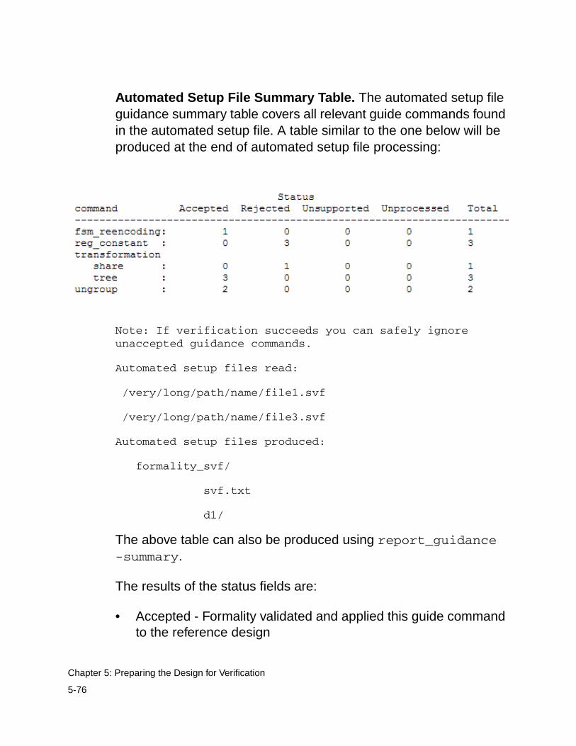
Automated Setup File Summary Table. The automated setup fileguidance summary table covers all relevant guide commands foundin the automated setup file. A table similar to the one below will beproduced at the end of automated setup file processing:
Note: If verification succeeds you can safely ignoreunaccepted guidance commands.
Automated setup files read:
/very/long/path/name/file1.svf
/very/long/path/name/file3.svf
Automated setup files produced:
formality_svf/
svf.txt
d1/
The above table can also be produced using report_guidance-summary.
The results of the status fields are:
• Accepted - Formality validated and applied this guide commandto the reference design
5-76
Chapter 5: Preparing the Design for Verification
• Rejected - Formality either could not validate or could not applythis guide command to the reference design
• Unsupported - Formality does not currently support some aspectof this guide command
• Unprocessed - Formality has not processed this guide command
For more information about the guide commands, see Appendix C,“Shell Commands” or the specific man page.
Automated Setup formality_svf Directory. Regardless of thenumber of .svf files read in, Formality will create a singleauto-decrypted text automated setup file (svf.txt) which representsthe ordered automated setup file guide commands read in. Allmessages related to guide commands generated will reference thisfile. This file, along with all decrypted dwsvf netlists, will be placedunder a single directory (formality_svf) in the current workingdirectory.
Users can easily examine the automated setup file contents ifneeded. In addition, if test cases are ever required, a single directorywill contain all the relevant guide commands and associated netlistdirectories.
The name of formality_svf/ will be tied to the name of theformality.log file and will follow the same "numbering" suffix that ituses. The integer number will always match that of theformality.log file.
Example:
set_svf foo1.svf foo2.svf foo3.svf
Formality will create:
5-77
Setting Up Designs
formality.logformality_svf/
svf.txtd1/…d2/……
The formality_svf/ directory is self-contained and can bemoved elsewhere without need of modification.
Reporting Automated Setup File Information. Severalcommands in Formality aid in reporting automated setup fileinformation.
find_svf_operation:
The find_svf_operation command takes guidance commandnames and automated setup file processing status as argumentsand returns a list of operation IDs.
Usage:
find_svf_operation # Get a list of automated setup fileoperation IDs
[-command ](Find operations of the specified command type(s))
[-status ] (Find operations with the specified status(es))
For command arguments, use what is found in the automated setupfile summary table. Note that you do not include the "guide_" prefix.When specifying transformation types, simply use the values map,tree, share, or merge.
For status arguments, use one of the following values: unprocessed,accepted, rejected, unsupported, or unaccepted.
5-78
Chapter 5: Preparing the Design for Verification
Refer to the man page for details on find_svf_operation.
report_svf_operation:
The report_svf_operation command will take a list of operationIDs and produce information regarding the same.
Usage:
Refer to the man page for details on report_svf_operation.
report_guidance:
There are three main uses of the report guidance command.
1.) Produce a summary table
This is the same as what is produced automatically after SVFprocessing.
report_guidance -summary
2.) Produce a "packed" Automated Setup File
report_svf_operation # Report information about specified operations
[-guide] (Report only the guide command itself)
[-message] (Report only the messages associated with theoperation)
[-summary] (Report a summary table of the specifiedoperations)
operationID_list (List of operation ID numbers)
5-79
Setting Up Designs
In future releases it is intended that Design Compiler will write out asingle "packed" automated setup file which will be a single file binaryrepresentation containing both the svf guide commands and thedwsvf netlists associated with them.
Formality supports this format, and you can write out these "packed"automated setup files.
For instance, given the following automated setup files andassociated dwsvf directories:
foo1.svf foo2.svf foo3.svf dwsvf-1234 dwsvf-2345dwsvf-3456
The following two commands will produce one single file (new.svf),which contains all the information found in the three automated setupfiles and the three dwsvf directories:
set_svf foo1.svf foo2.svf foo3.svf
report_guidance -to new.svf -pack
This packed automated setup file can also be read in by Formalityusing the following command:
set_svf new.svf
This command can also be used as an effective way of archiving allautomated setup file data.
3.) Produce a user defined text version of the Automated Setup file
report_guidance -to ascii.svf.txt
5-80
Chapter 5: Preparing the Design for Verification
This is very similar, but not formatted the same exact way as theautomatically generated formality_svf/svf.txt file. Because of this, it isnot reliable to use this file to correlate error messages for the currentrun, but could be used as input for any subsequent runs.
Automated Setup File Diagnostic Messages
Formality places detailed automated setup file diagnostic messagesin the formality.log file. Only messages pertaining to unacceptedguidance are produced and the line numbers correspond to linenumbers in the formality_svf/svf.txt file.
The following example is a formality.log file message:
SVF Operation 4 (line 47) - fsmInfo: Cannot find reference cell 'in_cur_reg[3]'.
Automated Setup File Conversion to Text
For every run, Formality will create the formality_svf/svf.txt file whichis a concatenated version of all svf read in. This file is to be used tocorrelate any messages produced during the run.
Formality can also be instructed to convert automatically theencrypted automated setup file information into ASCII text in placeduring the execution of the set_svf command. That is, a decryptedautomated setup file has the suffix .txt appended to the original filename in the original file location. To do this, enable the followingvariable which is disabled by default.
Set svf_auto_decrypt to true.
5-81
Setting Up Designs
Removing Information
Situations can arise that call for removing information from theFormality session prior to verification. This section describes how toremove designs, design libraries, technology libraries, andcontainers.
Removing Designs
Note:Before removing a design, be sure that its removal does notaffect the verification of surrounding logic. Surrounding logic candepend on states generated inside the removed design.
To remove one or more designs from the Formality environment, doone of the following:
The remove_design command is enabled only during setup mode.After you have executed the set_top command during theread-design flow as described in Chapter 4, Formality calls theset_black_box command when you specify remove_design.The design is treated as a black box for verification.
fm_shell GUI
Specify:
remove_design [-hierarchy ]design_list
1. Click the Reference or Implementationtab, and then the Read Design Files tab.
2. Click the Verilog, VHDL, or DB tab asapplicable to your design.
3. Select the design you want to remove.
4. Click Remove.
5-82
Chapter 5: Preparing the Design for Verification
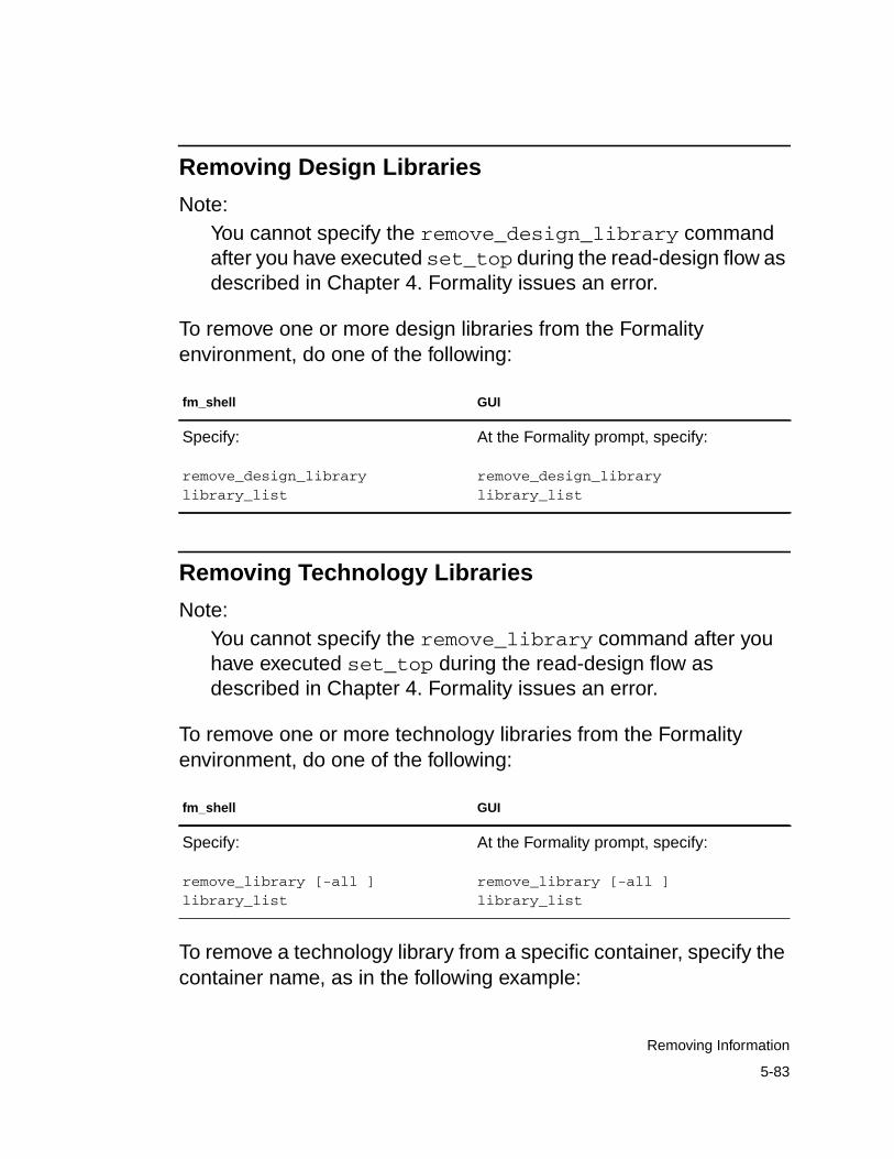
Removing Design Libraries
Note:You cannot specify the remove_design_library commandafter you have executed set_top during the read-design flow asdescribed in Chapter 4. Formality issues an error.
To remove one or more design libraries from the Formalityenvironment, do one of the following:
Removing Technology Libraries
Note:You cannot specify the remove_library command after youhave executed set_top during the read-design flow asdescribed in Chapter 4. Formality issues an error.
To remove one or more technology libraries from the Formalityenvironment, do one of the following:
To remove a technology library from a specific container, specify thecontainer name, as in the following example:
fm_shell GUI
Specify:
remove_design_librarylibrary_list
At the Formality prompt, specify:
remove_design_librarylibrary_list
fm_shell GUI
Specify:
remove_library [-all ]library_list
At the Formality prompt, specify:
remove_library [-all ]library_list
5-83
Removing Information
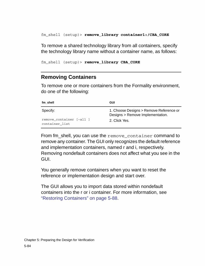
fm_shell (setup)> remove_library container1:/CBA_CORE
To remove a shared technology library from all containers, specifythe technology library name without a container name, as follows:
fm_shell (setup)> remove_library CBA_CORE
Removing Containers
To remove one or more containers from the Formality environment,do one of the following:
From fm_shell, you can use the remove_container command toremove any container. The GUI only recognizes the default referenceand implementation containers, named r and i, respectively.Removing nondefault containers does not affect what you see in theGUI.
You generally remove containers when you want to reset thereference or implementation design and start over.
The GUI allows you to import data stored within nondefaultcontainers into the r or i container. For more information, see“Restoring Containers” on page 5-88.
fm_shell GUI
Specify:
remove_container [-all ]container_list
1. Choose Designs > Remove Reference orDesigns > Remove Implementation.
2. Click Yes.
5-84
Chapter 5: Preparing the Design for Verification
Converting Objects to Black Boxes
Using black boxes in a designs can be beneficial when you are usinga bottom-up verification style for hierarchical designs. For example,during the course of verification, some large blocks in the lowerlevels of the design hierarchy can be successfully verified. After theyare verified, you might not want to spend time reverifying thesesubdesigns as you move up the hierarchy.
You can create black boxes in a design in one of three ways:
• After you have issued set_top on your design, use theset_black_box command on the individual design blocks ortechnology cells from the design library that you want convertedto black boxes.
• Use the hdlin_interface_only variable before you begin toread in your design objects. When the design is read in, theobjects you specified when setting the variable are black boxes.
• Read in your design, then issue set_top. If there are designreferences that cannot be found, by default the processterminates with an error. If you set thehdlin_unresolved_modules variable to black_box,Formality treats the missing references as black boxes.
Saving Information
Situations can arise that call for saving information in the Formalitysession. This section describes how to save individual containers aswell as how to save the entire Formality session.
5-85
Saving Information
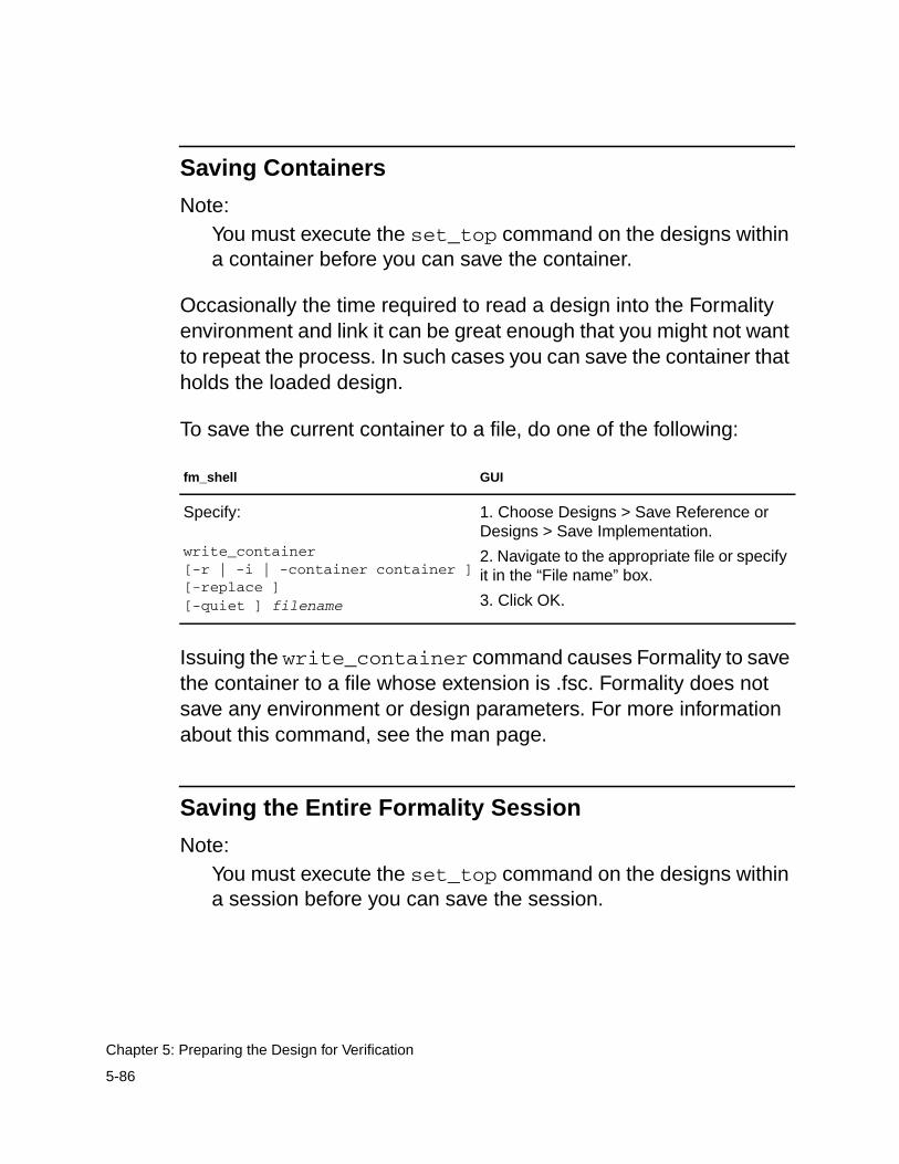
Saving Containers
Note:You must execute the set_top command on the designs withina container before you can save the container.
Occasionally the time required to read a design into the Formalityenvironment and link it can be great enough that you might not wantto repeat the process. In such cases you can save the container thatholds the loaded design.
To save the current container to a file, do one of the following:
Issuing the write_container command causes Formality to savethe container to a file whose extension is .fsc. Formality does notsave any environment or design parameters. For more informationabout this command, see the man page.
Saving the Entire Formality Session
Note:You must execute the set_top command on the designs withina session before you can save the session.
fm_shell GUI
Specify:
write_container[-r | -i | -container container ][-replace ][-quiet ] filename
1. Choose Designs > Save Reference orDesigns > Save Implementation.
2. Navigate to the appropriate file or specifyit in the “File name” box.
3. Click OK.
5-86
Chapter 5: Preparing the Design for Verification
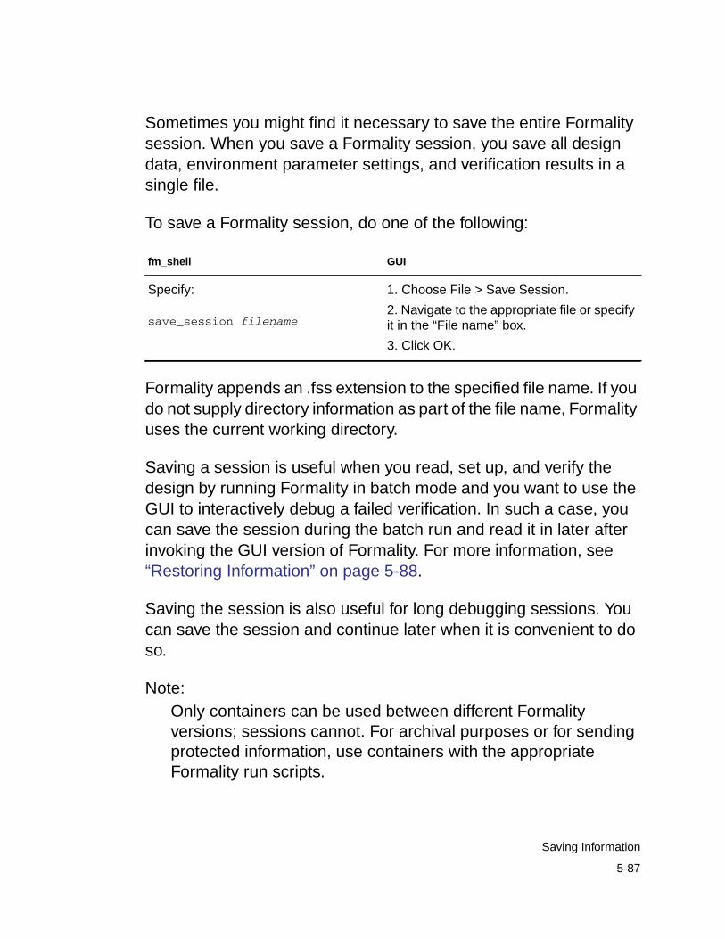
Sometimes you might find it necessary to save the entire Formalitysession. When you save a Formality session, you save all designdata, environment parameter settings, and verification results in asingle file.
To save a Formality session, do one of the following:
Formality appends an .fss extension to the specified file name. If youdo not supply directory information as part of the file name, Formalityuses the current working directory.
Saving a session is useful when you read, set up, and verify thedesign by running Formality in batch mode and you want to use theGUI to interactively debug a failed verification. In such a case, youcan save the session during the batch run and read it in later afterinvoking the GUI version of Formality. For more information, see“Restoring Information” on page 5-88.
Saving the session is also useful for long debugging sessions. Youcan save the session and continue later when it is convenient to doso.
Note:Only containers can be used between different Formalityversions; sessions cannot. For archival purposes or for sendingprotected information, use containers with the appropriateFormality run scripts.
fm_shell GUI
Specify:
save_session filename
1. Choose File > Save Session.
2. Navigate to the appropriate file or specifyit in the “File name” box.
3. Click OK.
5-87
Saving Information
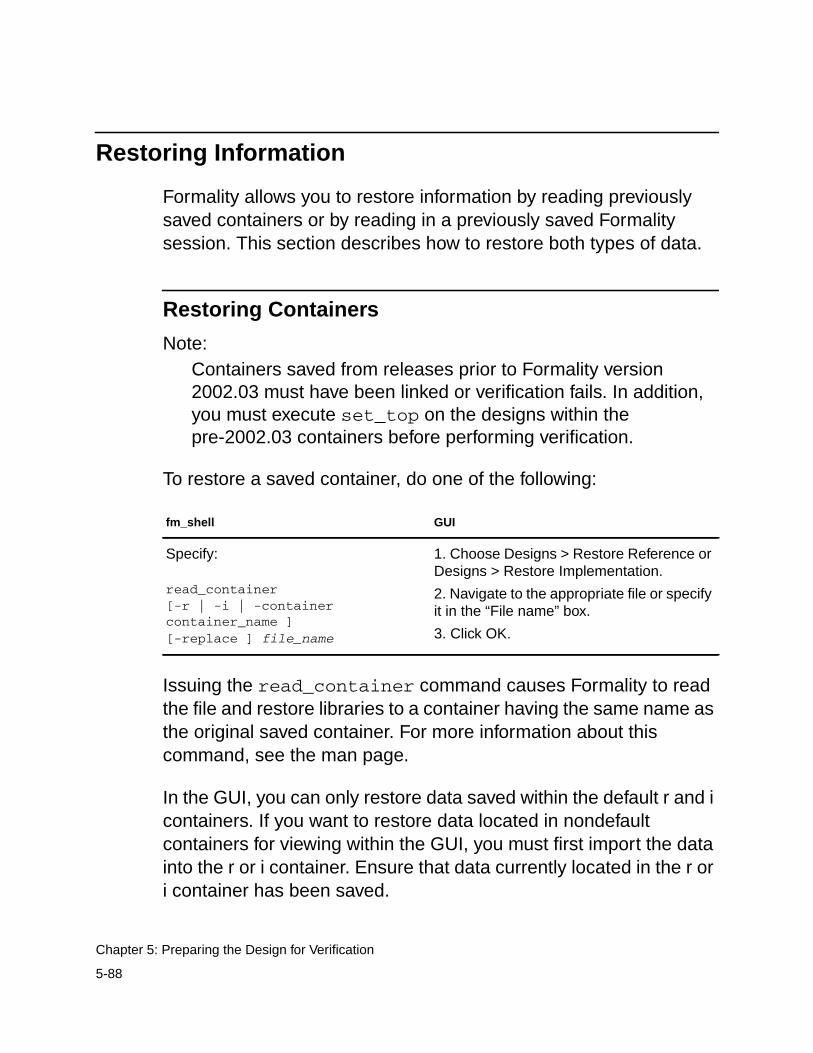
Restoring Information
Formality allows you to restore information by reading previouslysaved containers or by reading in a previously saved Formalitysession. This section describes how to restore both types of data.
Restoring Containers
Note:Containers saved from releases prior to Formality version2002.03 must have been linked or verification fails. In addition,you must execute set_top on the designs within thepre-2002.03 containers before performing verification.
To restore a saved container, do one of the following:
Issuing the read_container command causes Formality to readthe file and restore libraries to a container having the same name asthe original saved container. For more information about thiscommand, see the man page.
In the GUI, you can only restore data saved within the default r and icontainers. If you want to restore data located in nondefaultcontainers for viewing within the GUI, you must first import the datainto the r or i container. Ensure that data currently located in the r ori container has been saved.
fm_shell GUI
Specify:
read_container[-r | -i | -containercontainer_name ][-replace ] file_name
1. Choose Designs > Restore Reference orDesigns > Restore Implementation.
2. Navigate to the appropriate file or specifyit in the “File name” box.
3. Click OK.
5-88
Chapter 5: Preparing the Design for Verification
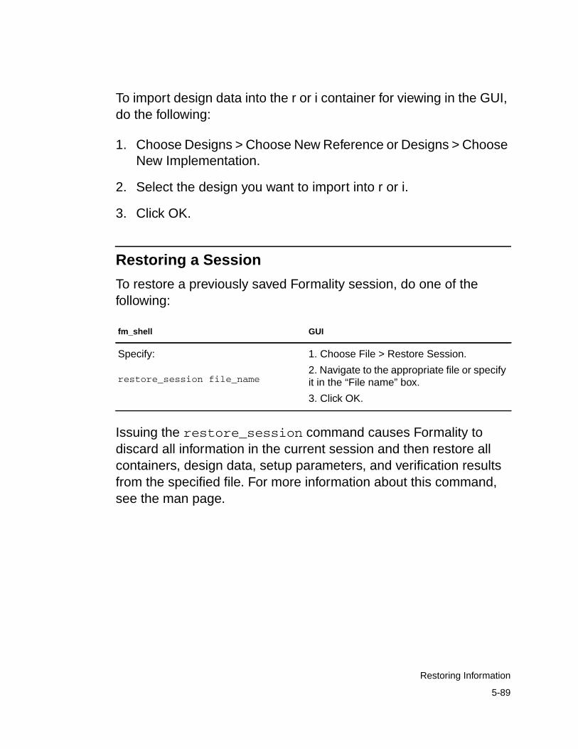
To import design data into the r or i container for viewing in the GUI,do the following:
1. Choose Designs > Choose New Reference or Designs > ChooseNew Implementation.
2. Select the design you want to import into r or i.
3. Click OK.
Restoring a Session
To restore a previously saved Formality session, do one of thefollowing:
Issuing the restore_session command causes Formality todiscard all information in the current session and then restore allcontainers, design data, setup parameters, and verification resultsfrom the specified file. For more information about this command,see the man page.
fm_shell GUI
Specify:
restore_session file_name
1. Choose File > Restore Session.
2. Navigate to the appropriate file or specifyit in the “File name” box.
3. Click OK.
5-89
Restoring Information

5-90
Chapter 5: Preparing the Design for Verification
6Compare Point Matching and Verification 6
After you have prepared your verification environment and set upyour design, you are ready to match compare points and then verifythe design. This chapter describes how to match compare points andverify one design against another. It also offers some tips for batchverifications, interpreting results, and saving data.
This chapter includes the following sections:
• Matching Compare Points
• Performing Verification
• Reporting and Interpreting Results
This chapter’s subject matter pertains to the boxes outlined inFigure 6-1.
6-1
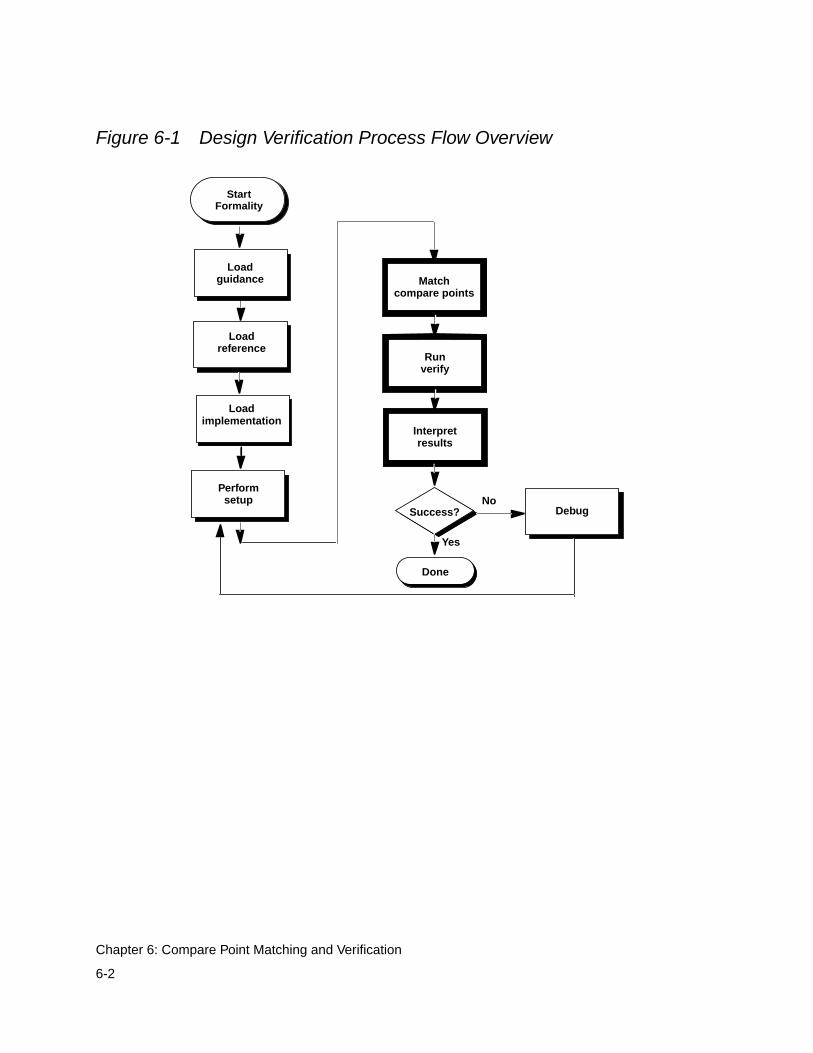
Figure 6-1 Design Verification Process Flow Overview
Interpretresults
Performsetup
Runverify
Success?No
Yes
Done
Matchcompare points
Loadreference
Loadimplementation
Debug
StartFormality
Loadguidance
6-2
Chapter 6: Compare Point Matching and Verification
Matching Compare Points
Prior to verification, Formality must match compare points in thedesigns as described in “Compare Points” on page 1-25. Thismatching occurs automatically when you specify the verifycommand. If automatic matching results in unmatched points, youmust then view and troubleshoot the results. Unmatched comparepoints can result in nonequivalence of the two designs.
Formality allows you to match compare points in a separate stepprior to specifying the verify command. Consequently you caniteratively debug unmatched compare points, as follows:
• Perform compare point matching.
• Report unmatched points.
• Modify or undo results of the match, as needed.
• Debug the unmatched compare points.
• Repeat these steps incrementally, as needed, until all comparepoints are matched.
Performing compare point matching changes the operational modefrom setup to match even if matching was incomplete. Ensure thatyou have properly set up your design as specified in Chapter 5,“Preparing the Design for Verification,” because the followingcommands and variables cannot be changed in the matched state:
6-3
Matching Compare Points
set_cutpointremove_black_boxremove_constantremove_cutpointremove_designremove_inv_pushremove_objectremove_parameters -resolution -retimed -all_parametersremove_resistive_driversrename_objectset_black_boxset_constantset_directionset_equivalenceset_fsm_encodingset_fsm_state_vectorset_inv_pushset_parameters -resolution -retimedungroupuniquifyverification_assume_reg_initverification_auto_loop_breakverification_clock_gate_hold_modeverification_constant_prop_modeverification_inversion_pushverification_merge_duplicated_registersverification_set_undriven_signalsverification_use_partial_modeled_cells
You can return to setup mode by using the setup command, but thiscauses all points matched during match mode to becomeunmatched.
6-4
Chapter 6: Compare Point Matching and Verification
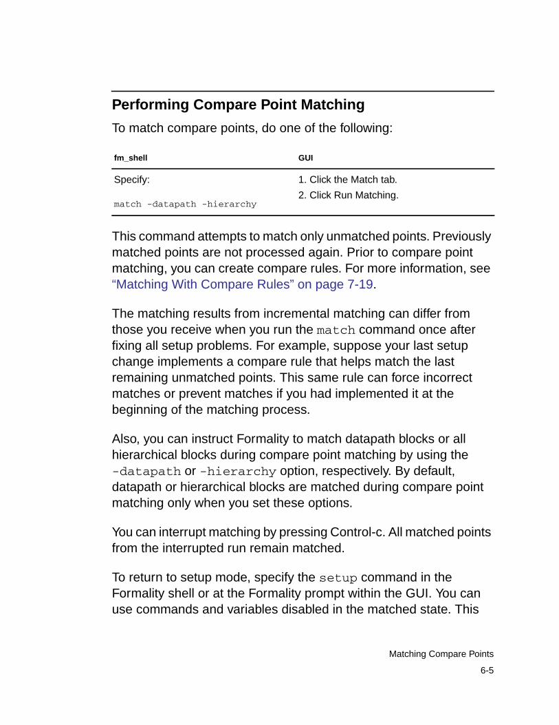
Performing Compare Point Matching
To match compare points, do one of the following:
This command attempts to match only unmatched points. Previouslymatched points are not processed again. Prior to compare pointmatching, you can create compare rules. For more information, see“Matching With Compare Rules” on page 7-19.
The matching results from incremental matching can differ fromthose you receive when you run the match command once afterfixing all setup problems. For example, suppose your last setupchange implements a compare rule that helps match the lastremaining unmatched points. This same rule can force incorrectmatches or prevent matches if you had implemented it at thebeginning of the matching process.
Also, you can instruct Formality to match datapath blocks or allhierarchical blocks during compare point matching by using the-datapath or -hierarchy option, respectively. By default,datapath or hierarchical blocks are matched during compare pointmatching only when you set these options.
You can interrupt matching by pressing Control-c. All matched pointsfrom the interrupted run remain matched.
To return to setup mode, specify the setup command in theFormality shell or at the Formality prompt within the GUI. You canuse commands and variables disabled in the matched state. This
fm_shell GUI
Specify:
match -datapath -hierarchy
1. Click the Match tab.
2. Click Run Matching.
6-5
Matching Compare Points
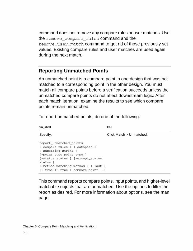
command does not remove any compare rules or user matches. Usethe remove_compare_rules command and theremove_user_match command to get rid of those previously setvalues. Existing compare rules and user matches are used againduring the next match.
Reporting Unmatched Points
An unmatched point is a compare point in one design that was notmatched to a corresponding point in the other design. You mustmatch all compare points before a verification succeeds unless theunmatched compare points do not affect downstream logic. Aftereach match iteration, examine the results to see which comparepoints remain unmatched.
To report unmatched points, do one of the following:
This command reports compare points, input points, and higher-levelmatchable objects that are unmatched. Use the options to filter thereport as desired. For more information about options, see the manpage.
fm_shell GUI
Specify:
report_unmatched_points[-compare_rules ] [-datapath ][-substring string ][-point_type point_type ][-status status ] [-except_statusstatus ][-method matching_method ] [-last ][[-type ID_type ] compare_point...]
Click Match > Unmatched.
6-6
Chapter 6: Compare Point Matching and Verification
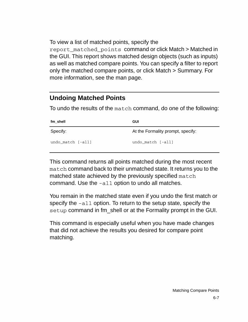
To view a list of matched points, specify thereport_matched_points command or click Match > Matched inthe GUI. This report shows matched design objects (such as inputs)as well as matched compare points. You can specify a filter to reportonly the matched compare points, or click Match > Summary. Formore information, see the man page.
Undoing Matched Points
To undo the results of the match command, do one of the following:
This command returns all points matched during the most recentmatch command back to their unmatched state. It returns you to thematched state achieved by the previously specified matchcommand. Use the -all option to undo all matches.
You remain in the matched state even if you undo the first match orspecify the -all option. To return to the setup state, specify thesetup command in fm_shell or at the Formality prompt in the GUI.
This command is especially useful when you have made changesthat did not achieve the results you desired for compare pointmatching.
fm_shell GUI
Specify:
undo_match [-all]
At the Formality prompt, specify:
undo_match [-all]
6-7
Matching Compare Points
Debugging Unmatched Points
After you report the unmatched compare points, you can use any orall of the following user-specified techniques to match them:
One of the most common reasons for unmatched compare points isdesign transformations incurred during Design Compiler processing.The intent of these transformations is not to change the features ofthe design, but to optimize it for speed or by area, or to prepare thedesign for back-end tools. Unfortunately, such designtransformations can cause severe compare point matching problemsbecause object names often change significantly.
Common transformations include moving features up and down thedesign hierarchy, explicitly applying name rules to objects in thedesign, and eliminating constant registers.
To resolve compare point mismatches caused by Design Compilerdesign transformations, you can specify a change file generated byDesign Compiler as input to Formality. This encrypted file lists all thename changes incurred during Design Compiler processing.Formality uses this file to map the new names back to their originalsfor compare point matching.
• Matching with user-supplied names
• Matching with compare rules
• Matching with name subset
• Renaming user-supplied names or mapping file
Each matching technique is described in detail in “UnmatchedPoints” on page 7-15.
6-8
Chapter 6: Compare Point Matching and Verification
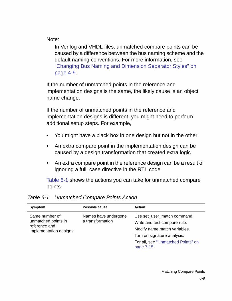
Note:In Verilog and VHDL files, unmatched compare points can becaused by a difference between the bus naming scheme and thedefault naming conventions. For more information, see“Changing Bus Naming and Dimension Separator Styles” onpage 4-9.
If the number of unmatched points in the reference andimplementation designs is the same, the likely cause is an objectname change.
If the number of unmatched points in the reference andimplementation designs is different, you might need to performadditional setup steps. For example,
• You might have a black box in one design but not in the other
• An extra compare point in the implementation design can becaused by a design transformation that created extra logic
• An extra compare point in the reference design can be a result ofignoring a full_case directive in the RTL code
Table 6-1 shows the actions you can take for unmatched comparepoints.
Table 6-1 Unmatched Compare Points Action
Symptom Possible cause Action
Same number ofunmatched points inreference andimplementation designs
Names have undergonea transformation
Use set_user_match command.
Write and test compare rule.
Modify name match variables.
Turn on signature analysis.
For all, see “Unmatched Points” onpage 7-15.
6-9
Matching Compare Points
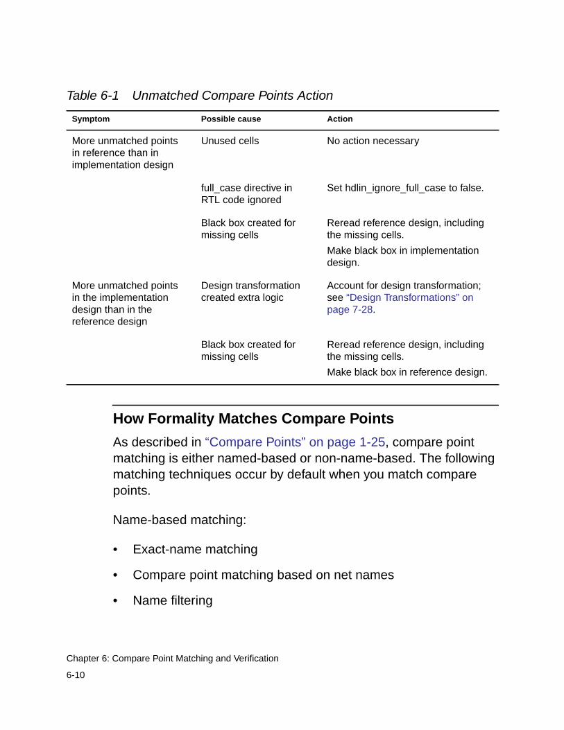
How Formality Matches Compare Points
As described in “Compare Points” on page 1-25, compare pointmatching is either named-based or non-name-based. The followingmatching techniques occur by default when you match comparepoints.
Name-based matching:
• Exact-name matching
• Compare point matching based on net names
• Name filtering
More unmatched pointsin reference than inimplementation design
Unused cells No action necessary
full_case directive inRTL code ignored
Set hdlin_ignore_full_case to false.
Black box created formissing cells
Reread reference design, includingthe missing cells.
Make black box in implementationdesign.
More unmatched pointsin the implementationdesign than in thereference design
Design transformationcreated extra logic
Account for design transformation;see “Design Transformations” onpage 7-28.
Black box created formissing cells
Reread reference design, includingthe missing cells.
Make black box in reference design.
Table 6-1 Unmatched Compare Points Action
Symptom Possible cause Action
6-10
Chapter 6: Compare Point Matching and Verification
Non-name-based matching:
• Topological equivalence
• Signature and topological analysis
These matching techniques are executed in the following order:
• Exact-name matching
• Name filtering
• Topological equivalence
• Signature analysis
• Compare point matching based on net names
Note:Four other user-specified matching techniques are alsoavailable, but you normally use them to debug unmatched points.For more information, see “Unmatched Points” on page 7-15.
After a technique succeeds in matching a compare point in onedesign to a compare point in the other design, that compare pointbecomes exempt from processing by other matching techniques.
All name matching in Formality is case-insensitive. The followingsections describe each default compare point matching technique.
6-11
Matching Compare Points
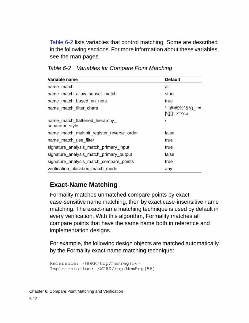
Table 6-2 lists variables that control matching. Some are describedin the following sections. For more information about these variables,see the man pages.
Exact-Name Matching
Formality matches unmatched compare points by exactcase-sensitive name matching, then by exact case-insensitive namematching. The exact-name matching technique is used by default inevery verification. With this algorithm, Formality matches allcompare points that have the same name both in reference andimplementation designs.
For example, the following design objects are matched automaticallyby the Formality exact-name matching technique:
Reference: /WORK/top/memreg(56)Implementation: /WORK/top/MemReg(56)
Table 6-2 Variables for Compare Point Matching
Variable name Default
name_match all
name_match_allow_subset_match strict
name_match_based_on_nets true
name_match_filter_chars ‘~!@#$%^&*()_+=|\{}[]”:;<>?,./
name_match_flattened_hierarchy_separator_style
/
name_match_multibit_register_reverse_order false
name_match_use_filter true
signature_analysis_match_primary_input true
signature_analysis_match_primary_output false
signature_analysis_match_compare_points true
verification_blackbox_match_mode any
6-12
Chapter 6: Compare Point Matching and Verification
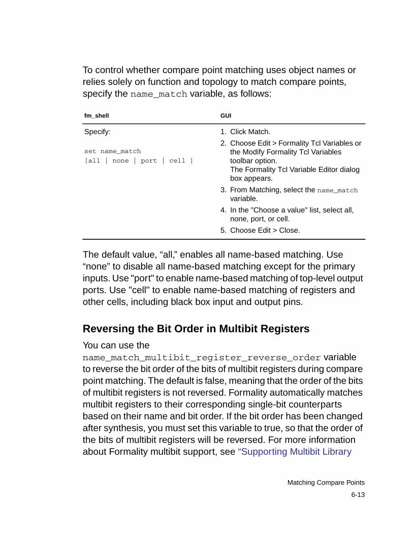
To control whether compare point matching uses object names orrelies solely on function and topology to match compare points,specify the name_match variable, as follows:
The default value, “all,” enables all name-based matching. Use“none” to disable all name-based matching except for the primaryinputs. Use "port" to enable name-based matching of top-level outputports. Use "cell" to enable name-based matching of registers andother cells, including black box input and output pins.
Reversing the Bit Order in Multibit Registers
You can use thename_match_multibit_register_reverse_order variableto reverse the bit order of the bits of multibit registers during comparepoint matching. The default is false, meaning that the order of the bitsof multibit registers is not reversed. Formality automatically matchesmultibit registers to their corresponding single-bit counterpartsbased on their name and bit order. If the bit order has been changedafter synthesis, you must set this variable to true, so that the order ofthe bits of multibit registers will be reversed. For more informationabout Formality multibit support, see “Supporting Multibit Library
fm_shell GUI
Specify:
set name_match
[all | none | port | cell ]
1. Click Match.
2. Choose Edit > Formality Tcl Variables orthe Modify Formality Tcl Variablestoolbar option.The Formality Tcl Variable Editor dialogbox appears.
3. From Matching, select the name_matchvariable.
4. In the "Choose a value" list, select all,none, port, or cell.
5. Choose Edit > Close.
6-13
Matching Compare Points
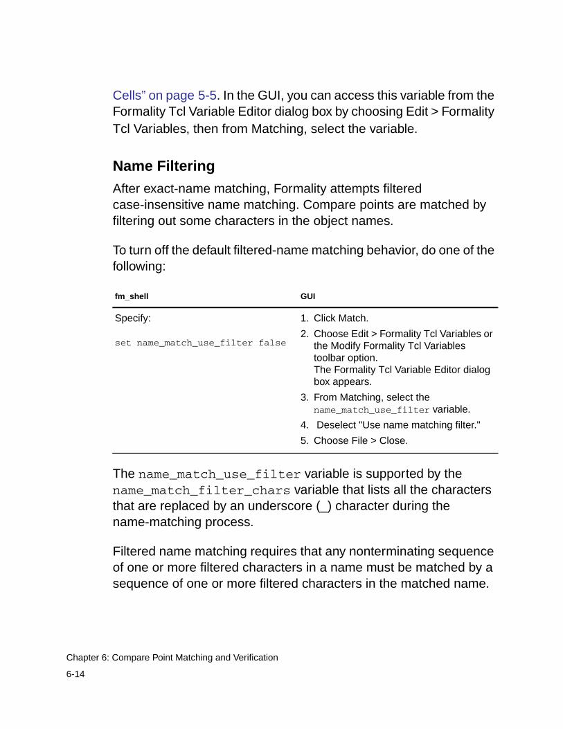
Cells” on page 5-5. In the GUI, you can access this variable from theFormality Tcl Variable Editor dialog box by choosing Edit > FormalityTcl Variables, then from Matching, select the variable.
Name Filtering
After exact-name matching, Formality attempts filteredcase-insensitive name matching. Compare points are matched byfiltering out some characters in the object names.
To turn off the default filtered-name matching behavior, do one of thefollowing:
The name_match_use_filter variable is supported by thename_match_filter_chars variable that lists all the charactersthat are replaced by an underscore (_) character during thename-matching process.
Filtered name matching requires that any nonterminating sequenceof one or more filtered characters in a name must be matched by asequence of one or more filtered characters in the matched name.
fm_shell GUI
Specify:
set name_match_use_filter false
1. Click Match.
2. Choose Edit > Formality Tcl Variables orthe Modify Formality Tcl Variablestoolbar option.The Formality Tcl Variable Editor dialogbox appears.
3. From Matching, select thename_match_use_filter variable.
4. Deselect "Use name matching filter."
5. Choose File > Close.
6-14
Chapter 6: Compare Point Matching and Verification
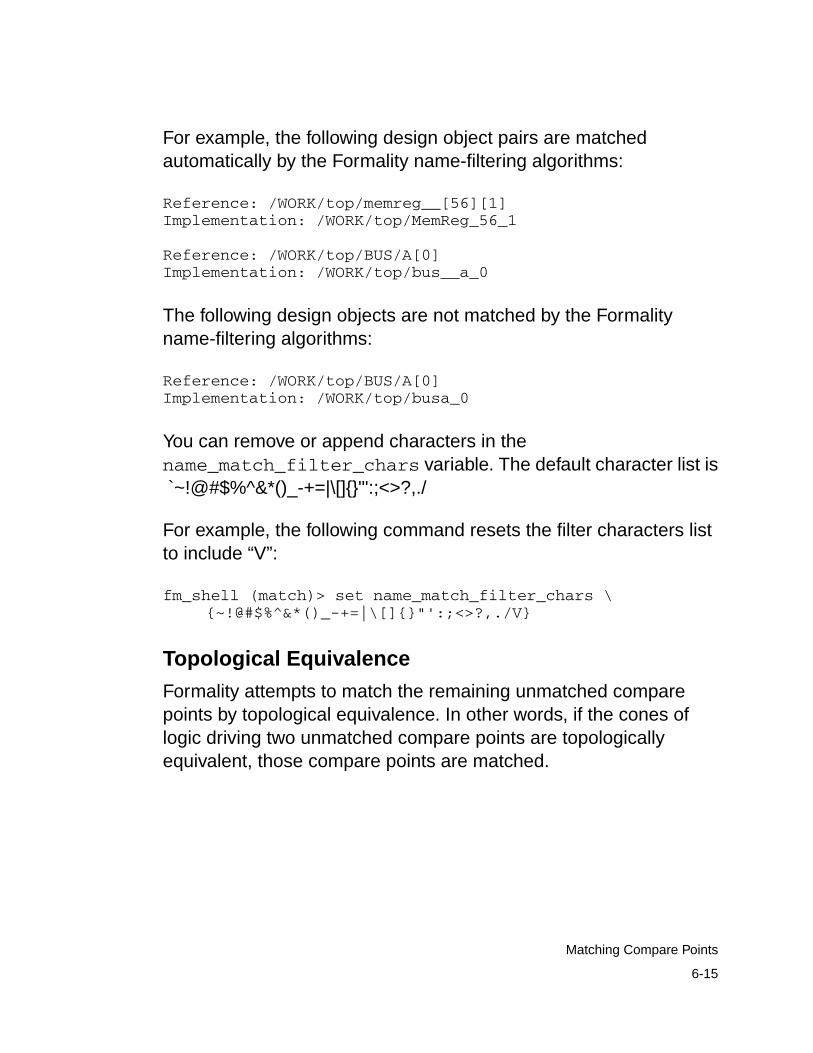
For example, the following design object pairs are matchedautomatically by the Formality name-filtering algorithms:
Reference: /WORK/top/memreg__[56][1]Implementation: /WORK/top/MemReg_56_1
Reference: /WORK/top/BUS/A[0]Implementation: /WORK/top/bus__a_0
The following design objects are not matched by the Formalityname-filtering algorithms:
Reference: /WORK/top/BUS/A[0]Implementation: /WORK/top/busa_0
You can remove or append characters in thename_match_filter_chars variable. The default character list is `~!@#$%^&*()_-+=|\[]{}"':;<>?,./
For example, the following command resets the filter characters listto include “V”:
fm_shell (match)> set name_match_filter_chars \{~!@#$%^&*()_-+=|\[]{}"':;<>?,./V}
Topological Equivalence
Formality attempts to match the remaining unmatched comparepoints by topological equivalence. In other words, if the cones oflogic driving two unmatched compare points are topologicallyequivalent, those compare points are matched.
6-15
Matching Compare Points
Signature Analysis
Signature analysis is an iterative analysis of the compare points’functional and topological signatures. Functional signatures arederived from random pattern simulation; topological signatures arederived from fanin cone topology.
The signature analysis algorithm uses simulation to produce outputdata patterns, or signatures, of output values at registers. Thesimulation process in signature analysis is used to uniquely identifya controlled node.
For example, if a vector makes a register pair go to a 1 and all othercontrolled registers go to a 0 in both designs, signature analysis hascompleted one match.
For signature analysis to work, the primary input ports from bothdesigns must have matching names or you must have manuallymatched them by using the set_user_match,set_compare_rule, or rename_object command.
During signature analysis, Formality also automatically attempts tomatch previously unmatched datapath and hierarchical blocks andtheir pins. To turn off automatic matching of datapath or hierarchicalblocks and pins, set thesignature_analysis_match_datapath orsignature_analysis_match_hierarchy variable to false,respectively. If you notice a performance decrease when runninghierarchical verification, you can change the setting ofsignature_analysis_match_hierarchy to false.
6-16
Chapter 6: Compare Point Matching and Verification
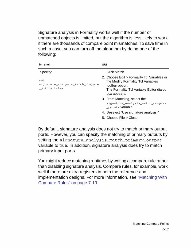
Signature analysis in Formality works well if the number ofunmatched objects is limited, but the algorithm is less likely to workif there are thousands of compare point mismatches. To save time insuch a case, you can turn off the algorithm by doing one of thefollowing:
By default, signature analysis does not try to match primary outputports. However, you can specify the matching of primary outputs bysetting the signature_analysis_match_primary_outputvariable to true. In addition, signature analysis does try to matchprimary input ports.
You might reduce matching runtimes by writing a compare rule ratherthan disabling signature analysis. Compare rules, for example, workwell if there are extra registers in both the reference andimplementation designs. For more information, see “Matching WithCompare Rules” on page 7-19.
fm_shell GUI
Specify:
setsignature_analysis_match_compare_points false
1. Click Match.
2. Choose Edit > Formality Tcl Variables orthe Modify Formality Tcl Variablestoolbar option.The Formality Tcl Variable Editor dialogbox appears.
3. From Matching, select thesignature_analysis_match_compare_points variable.
4. Deselect "Use signature analysis."
5. Choose File > Close.
6-17
Matching Compare Points
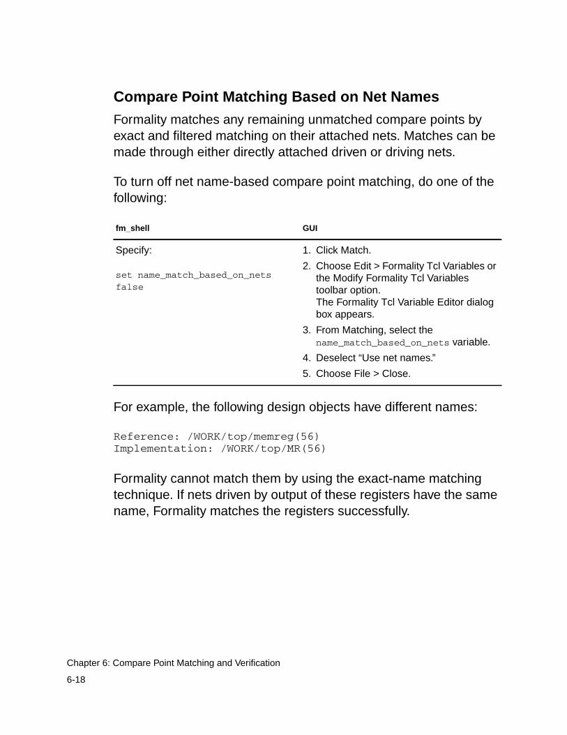
Compare Point Matching Based on Net Names
Formality matches any remaining unmatched compare points byexact and filtered matching on their attached nets. Matches can bemade through either directly attached driven or driving nets.
To turn off net name-based compare point matching, do one of thefollowing:
For example, the following design objects have different names:
Reference: /WORK/top/memreg(56)Implementation: /WORK/top/MR(56)
Formality cannot match them by using the exact-name matchingtechnique. If nets driven by output of these registers have the samename, Formality matches the registers successfully.
fm_shell GUI
Specify:
set name_match_based_on_netsfalse
1. Click Match.
2. Choose Edit > Formality Tcl Variables orthe Modify Formality Tcl Variablestoolbar option.The Formality Tcl Variable Editor dialogbox appears.
3. From Matching, select thename_match_based_on_nets variable.
4. Deselect “Use net names.”
5. Choose File > Close.
6-18
Chapter 6: Compare Point Matching and Verification
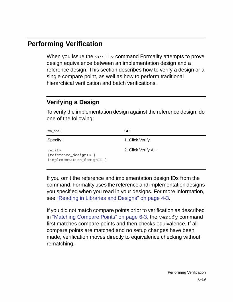
Performing Verification
When you issue the verify command Formality attempts to provedesign equivalence between an implementation design and areference design. This section describes how to verify a design or asingle compare point, as well as how to perform traditionalhierarchical verification and batch verifications.
Verifying a Design
To verify the implementation design against the reference design, doone of the following:
If you omit the reference and implementation design IDs from thecommand, Formality uses the reference and implementation designsyou specified when you read in your designs. For more information,see “Reading in Libraries and Designs” on page 4-3.
If you did not match compare points prior to verification as describedin “Matching Compare Points” on page 6-3, the verify commandfirst matches compare points and then checks equivalence. If allcompare points are matched and no setup changes have beenmade, verification moves directly to equivalence checking withoutrematching.
fm_shell GUI
Specify:
verify[reference_designID ][implementation_designID ]
1. Click Verify.
2. Click Verify All.
6-19
Performing Verification
If matching was performed but there are unmatched points or thesetup was altered, Formality attempts to match remainingunmatched points prior to equivalence checking. The verifycommand does not rematch already matched compare points.
To force the verify command to rematch everything, specify theundo_match -all command beforehand.
Formality makes an initial super-low-effort verification attempt on allcompare points before proceeding to the remaining compare pointswith matching hierarchy by signature analysis and high-effortverification. This initial attempt can significantly improveperformance by quickly verifying the easy-to-solve compare pointslocated throughout your designs. Set theverification_super_low_effort_first_pass variable totrue (the default) to force the verify command to run thissuper-low-effort verification first. Afterward, Formality proceeds withverifying all the remaining compare points.
Verification automatically runs in incremental mode, controlled by theverification_incremental_mode variable (true by default).Each verify command attempts to verify only compare points inthe unverified state. This means that after the verification iscompleted or has stopped, upon reissue of verify, the status ofpreviously passing and failing points is retained and verificationcontinues for unverified points. If matching setup has changedthrough use of set_user_match or set_compare_rule,Formality determines which compare points are affected, movesthem to the unverified state, and reverifies them. In addition, if theverification effort level has been raised, points that were aborted dueto complexity are also verified again. To force verify to reverify allcompare points, use the command’s -restart option.
6-20
Chapter 6: Compare Point Matching and Verification
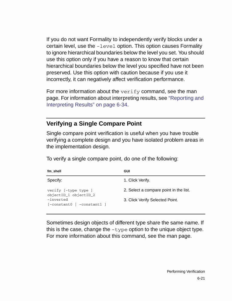
If you do not want Formality to independently verify blocks under acertain level, use the -level option. This option causes Formalityto ignore hierarchical boundaries below the level you set. You shoulduse this option only if you have a reason to know that certainhierarchical boundaries below the level you specified have not beenpreserved. Use this option with caution because if you use itincorrectly, it can negatively affect verification performance.
For more information about the verify command, see the manpage. For information about interpreting results, see “Reporting andInterpreting Results” on page 6-34.
Verifying a Single Compare Point
Single compare point verification is useful when you have troubleverifying a complete design and you have isolated problem areas inthe implementation design.
To verify a single compare point, do one of the following:
Sometimes design objects of different type share the same name. Ifthis is the case, change the -type option to the unique object type.For more information about this command, see the man page.
fm_shell GUI
Specify:
verify [-type type ]objectID_1 objectID_2-inverted[-constant0 | -constant1 ]
1. Click Verify.
2. Select a compare point in the list.
3. Click Verify Selected Point.
6-21
Performing Verification
Besides verifying single compare points between two designs, youcan also verify two points in the same design or verify an invertedrelationship between two points. To verify that a certain output porthas the same value as a certain input port in the same design, usethe command
verify $impl/input_port $impl/output_port
To verify an inverted relationship between two given points, use the-inverted switch to the verify command.
In addition, you can verify a single compare point with a constant 1or 0. Using either the -constant0 or -constant1 option to theverify command causes Formality to treat a point that evaluates toa constant as a special single compare point during verification. Youcan access this functionality through the GUI when you are in theMatch or Verify steps by using the Run menu from the main window’smenu bar. For more information about the -constant option, seethe verify command man page.
To verify a subset of compare points, see “Removing ComparePoints From the Verification Set” on page 6-22. For information aboutinterpreting results, see “Reporting and Interpreting Results” onpage 6-34.
Removing Compare Points From the Verification Set
You can elect to remove any matched compare points from theverification set. This is useful when you need to pinpoint problems ina failed verification.
6-22
Chapter 6: Compare Point Matching and Verification
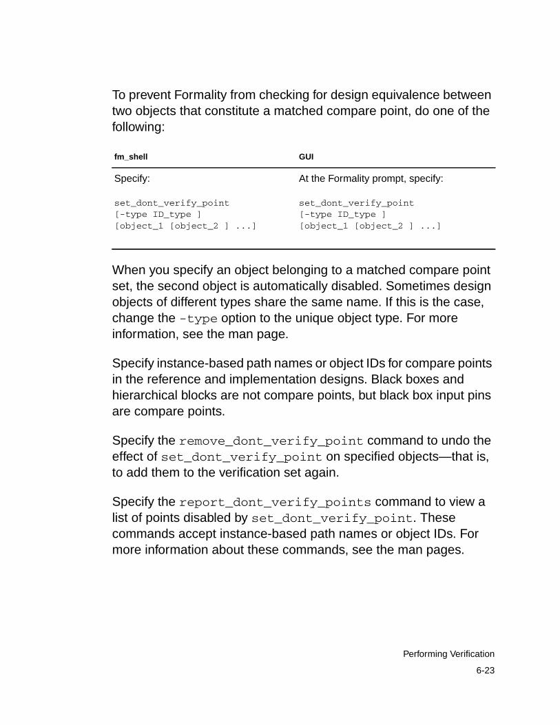
To prevent Formality from checking for design equivalence betweentwo objects that constitute a matched compare point, do one of thefollowing:
When you specify an object belonging to a matched compare pointset, the second object is automatically disabled. Sometimes designobjects of different types share the same name. If this is the case,change the -type option to the unique object type. For moreinformation, see the man page.
Specify instance-based path names or object IDs for compare pointsin the reference and implementation designs. Black boxes andhierarchical blocks are not compare points, but black box input pinsare compare points.
Specify the remove_dont_verify_point command to undo theeffect of set_dont_verify_point on specified objects—that is,to add them to the verification set again.
Specify the report_dont_verify_points command to view alist of points disabled by set_dont_verify_point. Thesecommands accept instance-based path names or object IDs. Formore information about these commands, see the man pages.
fm_shell GUI
Specify:
set_dont_verify_point[-type ID_type ][object_1 [object_2 ] ...]
At the Formality prompt, specify:
set_dont_verify_point[-type ID_type ][object_1 [object_2 ] ...]
6-23
Performing Verification
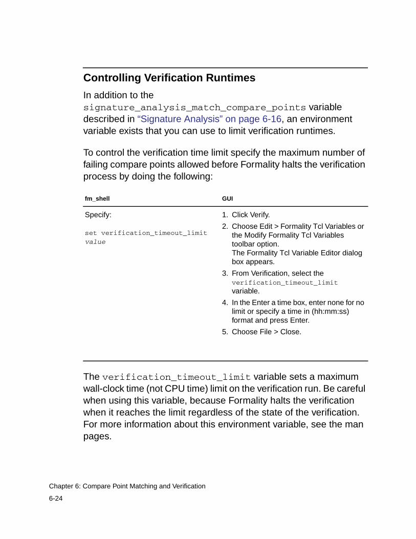
Controlling Verification Runtimes
In addition to thesignature_analysis_match_compare_points variabledescribed in “Signature Analysis” on page 6-16, an environmentvariable exists that you can use to limit verification runtimes.
To control the verification time limit specify the maximum number offailing compare points allowed before Formality halts the verificationprocess by doing the following:
The verification_timeout_limit variable sets a maximumwall-clock time (not CPU time) limit on the verification run. Be carefulwhen using this variable, because Formality halts the verificationwhen it reaches the limit regardless of the state of the verification.For more information about this environment variable, see the manpages.
fm_shell GUI
Specify:
set verification_timeout_limitvalue
1. Click Verify.
2. Choose Edit > Formality Tcl Variables orthe Modify Formality Tcl Variablestoolbar option.The Formality Tcl Variable Editor dialogbox appears.
3. From Verification, select theverification_timeout_limitvariable.
4. In the Enter a time box, enter none for nolimit or specify a time in (hh:mm:ss)format and press Enter.
5. Choose File > Close.
6-24
Chapter 6: Compare Point Matching and Verification
Distributing Verification Processes
You can execute Formality verification processes in parallel acrossseveral CPUs to increase performance. The following sectionsdescribe a typical user flow for working with parallel verification.
Setting Up the Distributed Environment
You must set the default working directory to FM_WORK/server; thisis the storage area for all the files required for exchanging data andinformation between the various machines. Make sure that thedirectory is accessible to each machine involved in the distributedprocess and that each machine is able to read from and write to thisdirectory. If this directory is not accessible from any one of theservers, or if you want to use another directory as a workingdirectory, you must change the working directory with thedistributed_work_directory Tcl variable. For example,
fm_shell (setup)> set distributed_work_directory /home/myname/dist/work
You specify the working directory by using an absolute path namestarting from the root of the system. Relative paths are notsupported.
After you set the working directory, you have two options forspecifying distribution. First, you can populate the distributed serverslist. For example,
fm_shell (setup)> add_distributed_processors {pandorahermes}
After defining the distributed servers list, you receive messages fromFormality similar to the following:
6-25
Performing Verification
Arch: sparc-64, Users: 22, Load: 2.18 2.14 2.17Arch: sparc-64, Users: 1, Load: 1.45 1.41 1.40
For each machine, Formality checks that fm_shell can be started onthe remote machine; that the release version matches the master;and that the distributed work directory is accessible. Formality printsthe type of platform (architecture), the number of users currentlylogged on to that machine, and the load average. There is a limit tothe number of servers you can add; you can have one master, withfour additional CPUs during verification. To avoid starting moredistributed servers than the number of available processors,determine the number of processors on that machine.
A second option for specifying distribution is to specify an LSFexecutable along with the number of servers. For example,
add_distributed_processors -lsf bsub_exec -nservers d-toptions"optionslist"
If using the -lsf option, you need to specify the path to the LSFsubmission executable.
You can use the report_distributed_processors commandto report the list of servers. For example,
fm_shell (setup)> report_distributed_processorsWorking directory ==> ``/remote/dtg654/fm/dfs'' (32bit)-------****-------MACHINE: pandora [ARCH: sparc-64]MACHINE: hermes [ARCH: sparc-64]-------****-------
Formality lists the name of the machine and its architecture; one lineper server. It also displays the working directory in the report alongwith the type of executable in use (32 bit or 64 bit). The master
6-26
Chapter 6: Compare Point Matching and Verification
machine automatically determines the executable type, subject tothe setting of the distributed_64bit_mode Tcl variable. Thisvariable is false by default; therefore, spawned servers run a 32-bitexecutable by default.
On occasion you might want to remove a server from the server list,for instance if you have an overloaded machine. In this situation, youuse the remove_distributed_processors command toremove servers from the server list. For example,
fm_shell (setup)> remove_distributed_processors pandorafm_shell (setup)> report_distributed_processorsWorking directory ==> ``/remote/dtg654/fm/dfs'' (32bit)-------****-------MACHINE: hermes [ARCH: sparc-64]-------****-------2.3.2 Starting Distributed Equivalence Checking
When you add servers and set thedistributed_verification_mode to enable (the default) Tclvariable, the verify command is executed in distributed mode:
fm_shell (setup)> verify ref:/WORK/test imp:/WORK/test
At the end of the verification, Formality reports verification results inthe same format as in serial process mode.
If unexpectedly one server process stops (for example, due to aninternal error or system problem), the entire verify command isimmediately terminated.
Verifying Your Environment
Whenever Formality starts a distributed server, it executes thefm_shell command. Your $PATH environment variable must findthe fm_shell command on each distributed host.
6-27
Performing Verification
Remote Shell Considerations. Formality relies on the rsh (remshfor HP platforms) UNIX command to start a process on a remotemachine. This command runs the login shell on the remote host andexecutes your shell initialization file. Interactive commands, runtimeerrors, and environment settings can cause remote execution to fail.The following notes can help diagnose such problems.
You need to have special privileges to start a distributed process withan rsh (or remsh) command. In many UNIX installations, thoseprivileges are given by default. However, the system administratormight have changed them. If you experience a problem startingservers and suspect it is due to a problem with rsh, you can testremote execution from the UNIX shell command prompt by using thefollowing command:
% rsh distributed_server_machine fm_shell
If you get an error message, its cause can be either commands orenvironment settings in your shell initialization file or privilegesettings that prevent you from executing a remote shell.
Tuning the Shell Resource File. Be aware of what is in your shellinitialization file, such as .cshrc and .profile, to avoid having shellcommands that have the following behavior:
• They interact with the user (that is, the shell asks you to entersomething from the keyboard). Because you do not have theability to answer (distributed processes are not interactive), theprocess might hang while waiting for an answer to a question itdoes not see.
• They require some GUI display. The DISPLAY environmentvariable is not set on the servers. X Windows clients fail.
6-28
Chapter 6: Compare Point Matching and Verification
If you have any trouble using add_distributed_processors,you might want to have a dedicated shell initialization file for runningdistributed tasks.
Interrupting Verification
To interrupt verification, press Control + c. Formality preserves thestate of the verification at the point you interrupted processing, andyou can report the results. You also can interrupt Formality duringautomatic compare point matching.
Performing Hierarchical Verification
By default, Formality incorporates a hybrid verification methodologythat combines the easy setup associated with flat verification with thebenefits of traditional hierarchical performance capacities. From auser perspective, Formality appears to be performing a flatverification, regardless of the design hierarchy, and all results arepresented in the context of the flat top-level design.
Formality allows you to perform a traditional hierarchical verificationthat is helpful when you want to view explicit, block-by-blockhierarchical results.
6-29
Performing Verification
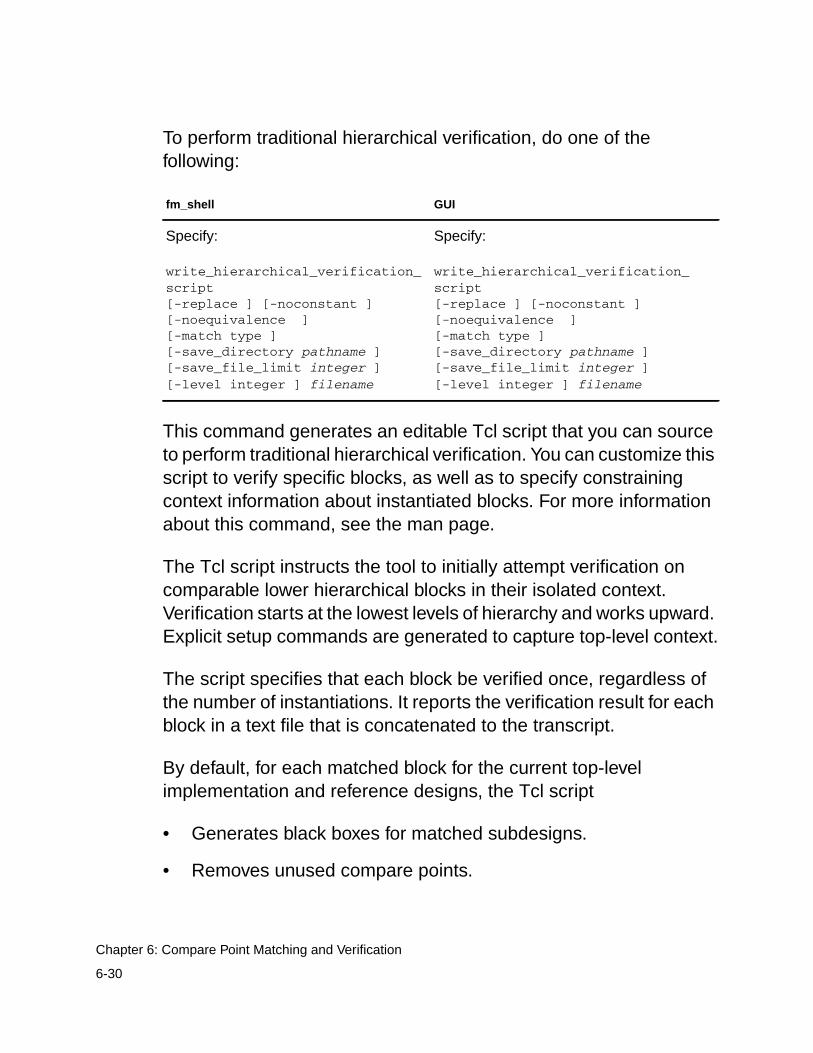
To perform traditional hierarchical verification, do one of thefollowing:
This command generates an editable Tcl script that you can sourceto perform traditional hierarchical verification. You can customize thisscript to verify specific blocks, as well as to specify constrainingcontext information about instantiated blocks. For more informationabout this command, see the man page.
The Tcl script instructs the tool to initially attempt verification oncomparable lower hierarchical blocks in their isolated context.Verification starts at the lowest levels of hierarchy and works upward.Explicit setup commands are generated to capture top-level context.
The script specifies that each block be verified once, regardless ofthe number of instantiations. It reports the verification result for eachblock in a text file that is concatenated to the transcript.
By default, for each matched block for the current top-levelimplementation and reference designs, the Tcl script
• Generates black boxes for matched subdesigns.
• Removes unused compare points.
fm_shell GUI
Specify:
write_hierarchical_verification_script[-replace ] [-noconstant ][-noequivalence ][-match type ][-save_directory pathname ][-save_file_limit integer ][-level integer ] filename
Specify:
write_hierarchical_verification_script[-replace ] [-noconstant ][-noequivalence ][-match type ][-save_directory pathname ][-save_file_limit integer ][-level integer ] filename
6-30
Chapter 6: Compare Point Matching and Verification
• Sets port matches for ports matched by means other than theirnames.
• Sets input port constants. Override this behavior by specifyingthe -noconstant option.
• Sets input port equivalences for unmatched input ports known tobe equivalent to other matched ports. Override this behavior byspecifying the -noequivalence option.
• Verifies the target block as a top-level design.
• Saves the Formality session if the verification fails. Override thisbehavior by specifying the -save_file_limit option.
The script ignores inconsistent setup information for port matches,constants, and equivalencies, and a comment appears in thegenerated script.
The script produced bywrite_hierarchical_verification_script is designed torun in the same session that it is created. If you run the hierarchicalverification script separately, you must manually insert commandsthat read and link the reference and implementation designs.
Using Batch Jobs
Running Formality shell commands in a batch job can save you timein situations where you have to verify the same design more thanonce. You can assemble a stream of commands, or script, that setsup the environment, loads the appropriate designs and libraries,performs the verification, and tests for a successful verification. Anytime you want to control verification through automatic processing,you can run a batch job.
6-31
Performing Verification
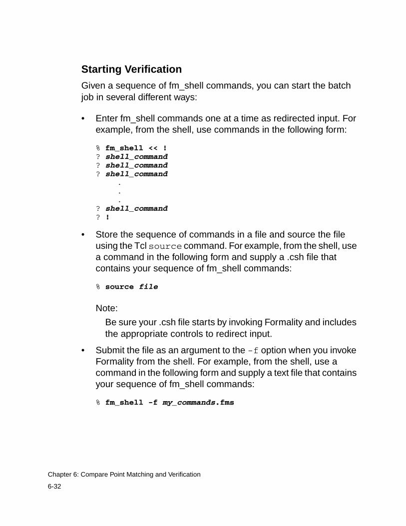
Starting Verification
Given a sequence of fm_shell commands, you can start the batchjob in several different ways:
• Enter fm_shell commands one at a time as redirected input. Forexample, from the shell, use commands in the following form:
% fm_shell << !? shell_command? shell_command? shell_command
.
.
.? shell_command? !
• Store the sequence of commands in a file and source the fileusing the Tcl source command. For example, from the shell, usea command in the following form and supply a .csh file thatcontains your sequence of fm_shell commands:
% source file
Note:
Be sure your .csh file starts by invoking Formality and includesthe appropriate controls to redirect input.
• Submit the file as an argument to the -f option when you invokeFormality from the shell. For example, from the shell, use acommand in the following form and supply a text file that containsyour sequence of fm_shell commands:
% fm_shell -f my_commands.fms
6-32
Chapter 6: Compare Point Matching and Verification
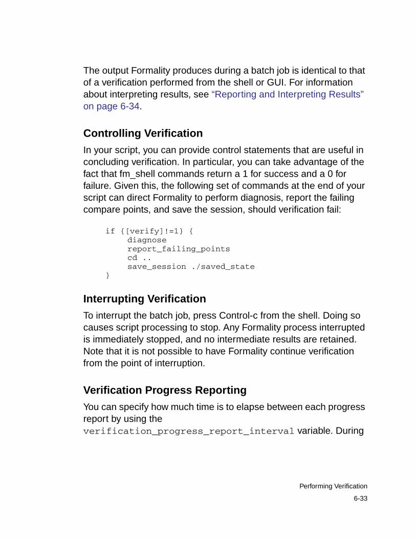
The output Formality produces during a batch job is identical to thatof a verification performed from the shell or GUI. For informationabout interpreting results, see “Reporting and Interpreting Results”on page 6-34.
Controlling Verification
In your script, you can provide control statements that are useful inconcluding verification. In particular, you can take advantage of thefact that fm_shell commands return a 1 for success and a 0 forfailure. Given this, the following set of commands at the end of yourscript can direct Formality to perform diagnosis, report the failingcompare points, and save the session, should verification fail:
if {[verify]!=1} {diagnosereport_failing_pointscd ..save_session ./saved_state
}
Interrupting Verification
To interrupt the batch job, press Control-c from the shell. Doing socauses script processing to stop. Any Formality process interruptedis immediately stopped, and no intermediate results are retained.Note that it is not possible to have Formality continue verificationfrom the point of interruption.
Verification Progress Reporting
You can specify how much time is to elapse between each progressreport by using theverification_progress_report_interval variable. During
6-33
Performing Verification
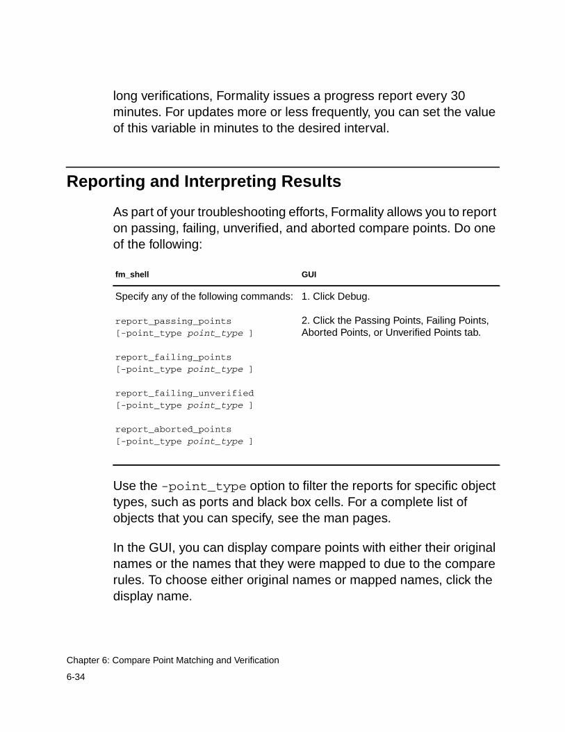
long verifications, Formality issues a progress report every 30minutes. For updates more or less frequently, you can set the valueof this variable in minutes to the desired interval.
Reporting and Interpreting Results
As part of your troubleshooting efforts, Formality allows you to reporton passing, failing, unverified, and aborted compare points. Do oneof the following:
Use the -point_type option to filter the reports for specific objecttypes, such as ports and black box cells. For a complete list ofobjects that you can specify, see the man pages.
In the GUI, you can display compare points with either their originalnames or the names that they were mapped to due to the comparerules. To choose either original names or mapped names, click thedisplay name.
fm_shell GUI
Specify any of the following commands:
report_passing_points[-point_type point_type ]
report_failing_points[-point_type point_type ]
report_failing_unverified[-point_type point_type ]
report_aborted_points[-point_type point_type ]
1. Click Debug.
2. Click the Passing Points, Failing Points,Aborted Points, or Unverified Points tab.
6-34
Chapter 6: Compare Point Matching and Verification
From the Formality shell, Formality displays information to standardoutput. This information is updated as the verification proceeds.From the transcript, you can see which design is being processedand observe the results of the verification. In the GUI, the transcriptis displayed in the transcript area.
During verification, Formality assigns one of three types of statusmessages for each compare point it identifies:
Passing
A passing point represents a compare point match that passesverification. Passing verification means that Formalitydetermined that the functions that define the values of the twocompare point design objects are functionally equivalent.
Failing
A failing point represents a compare point match that does notpass verification or does not consist of two design objects. Failingverification means that Formality determined that the two designobjects that constitute the compare point are not functionallyequivalent.
Unverified
An unverified point represents a compare point that has not yetbeen verified. Unverified points occur during the verificationprocess when the failing point limit has been reached or awall-clock time limit is exceeded. Formality normally stopsverification after 20 failing points have been found.
Aborted
An aborted point represents a compare point that Formality didnot determine to be either passing or failing. The cause can beeither a combinational loop that Formality cannot breakautomatically or a compare point that is too difficult to verify.
6-35
Reporting and Interpreting Results
Based on the preceding categories, Formality classifies finalverification results in one of the following ways:
Succeeded
The implementation design was determined to be functionallyequivalent to the reference design. All compare points passedverification.
Failed
The implementation design was determined to be not functionallyequivalent to the reference design. Formality could notsuccessfully match all design objects in the reference design withcomparable objects in the implementation design, or at least onedesign object in the reference design was determinednonequivalent to its comparable object in the implementationdesign (a compare point failure).
If verification is interrupted, either because you press Control-cor a user-defined time-out occurs (such as the CPU time limit),and if at least one failing point was detected prior to theinterruption, Formality reports a verification failure.
Inconclusive
Formality could not determine whether the reference andimplementation designs are equivalent. This situation occurs inthe following cases:
- A matched pair of compare points was too difficult to verify,causing an “aborted” compare point, and no failing points werefound elsewhere in the design.
- The verification was interrupted, either because you pressedControl-c or a user-defined time-out occurred, and no failingcompare points were detected prior to the interruption.
6-36
Chapter 6: Compare Point Matching and Verification

For information about what to look for when you have an inconclusiveverification due to an aborted compare point, see “Handling DesignsWhen Verification Is Incomplete” on page 7-4.
If a verification is inconclusive because it was interrupted, you mightget partial verification results. You can create reports on the partialverification results.
6-37
Reporting and Interpreting Results

6-38
Chapter 6: Compare Point Matching and Verification
7Debugging Failed Design Verifications 7
This chapter describes procedures that help you find problem areasin a design that fails verification.
It contains the following sections:
• Debugging Process Flow
• Gathering Information
• Handling Designs When Verification Is Incomplete
• Determining Failure Causes
• Debugging by Using Diagnosis
• Debugging by Using Logic Cones
• Eliminating Setup Possibilities
• Working With Schematics
7-1
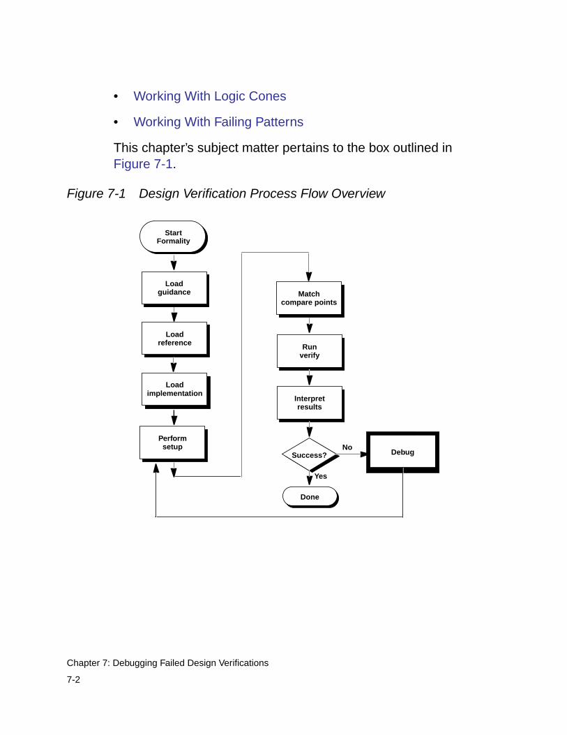
• Working With Logic Cones
• Working With Failing Patterns
This chapter’s subject matter pertains to the box outlined inFigure 7-1.
Figure 7-1 Design Verification Process Flow Overview
Interpretresults
Performsetup
Runverify
Success?No
Yes
Debug
Done
Matchcompare points
Loadreference
Loadimplementation
StartFormality
Loadguidance
7-2
Chapter 7: Debugging Failed Design Verifications
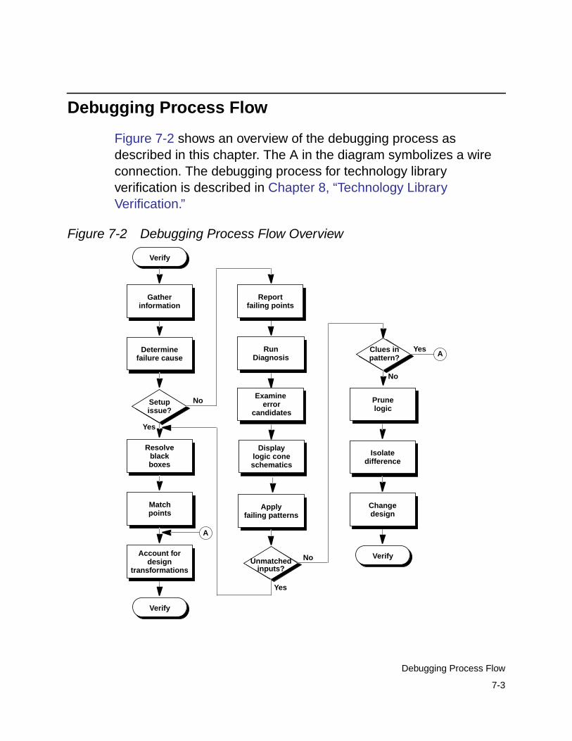
Debugging Process Flow
Figure 7-2 shows an overview of the debugging process asdescribed in this chapter. The A in the diagram symbolizes a wireconnection. The debugging process for technology libraryverification is described in Chapter 8, “Technology LibraryVerification.”
Figure 7-2 Debugging Process Flow Overview
Matchpoints
Verify
Gatherinformation
Determine
Resolveblack
Applyfailing patterns
Account fordesign
RunDiagnosis
Displaylogic cone
Unmatched No
Yes
Change
Setup No
Yes
issue?
Verify
boxes
transformations
schematics
inputs?
Prunelogic
Isolatedifference
Clues in
No
Yespattern?
Verify
design
A
Afailure cause
Reportfailing points
Examine error
candidates
7-3
Debugging Process Flow
Gathering Information
When a verification run reports that the designs are not equivalent,failure is due either to an incorrect setup or to a logical designdifference between the two designs. Formality provides informationthat can help you determine the cause of the verification failure. Theinformation sources are the following:
• The transcript window provides information about verificationstatus, black box creation, and simulation/synthesis mismatches.
• The formality.log file provides a complete list of black boxes in thedesign, assumptions made about directions of black box pins,and a list of multiply driven nets.
• Reports contain data on every compare point that affects theverification output. These reports are named report_failing,report_passing, and report_aborted.
This chapter describes when and how to use the various informationsources during the debugging process.
Handling Designs When Verification Is Incomplete
Occasionally, Formality encounters a design that cannot be verifiedbecause it is particularly complex. For example, asynchronousstate-holding loops can cause Formality to abort verification if youdid not check for their existence prior to executing the verifycommand. For more information, see “Eliminating AsynchronousState-Holding Loops” on page 5-10.
7-4
Chapter 7: Debugging Failed Design Verifications
The following steps provide a strategy to apply when verificationdoes not finish due to a design difficulty. Note that these steps aredifferent from those presented in “Determining Failure Causes” onpage 7-7, which describes what to do when verification finishes butfails.
Note:Incomplete verifications can occur when Formality reaches aprespecified number of failing compare points. This limit causesFormality to stop processing. Use theverification_failing_point_limit variable to adjustthe limit as needed.
1. If you have both aborted points and failing points, locate and fixthe failing compare points. For strategies about debugging failedcompare points, see “Debugging Unmatched Points” onpage 6-8.
2. Verify the design again. Fixing the failing compare points cansometimes eliminate the aborted points.
3. After eliminating all failing compare points, isolate the problem inthe design to the smallest possible block.
4. Declare the failing blocks as black boxes by using theset_black_box command. The set_black_box commandallows you to specify the designs that you want to black box. Formore information about this command, see the man page.
Alternatively, you can insert cutpoint black boxes to simplifyhard-to-verify designs, as described in “Working With Cutpoints”on page 5-12.
5. Verify the implementation design again. This time the verificationshould finish. However, the problem block remains unverified.
7-5
Handling Designs When Verification Is Incomplete
6. Use an alternative method to prove the functionality of theisolated problem block. For example, in a multiplier example, usea conventional simulation tool to prove that the multiplier havingthe different architecture in the implementation design isfunctionally equivalent to the multiplier in the reference design.
At this point, you have proved the problem block to be equivalentand you have proved the rest of the implementation designequivalent. One proof is accomplished through a conventionalsimulation tool, and the other is accomplished through Formality.Both proofs combined are sufficient to verify the designs asequal.
Establish the existing implementation design as the newreference design. This substitution follows the recommendedincremental verification technique described in Figure 1-1 onpage 1-5.
7. Prior to running verification a second time, match by hand anyequivalent multipliers that Formality has not automaticallymatched in the reference and implementation designs. Manuallymatching the multipliers aids the solver in successfully matchingremaining multipliers. Use the report_unmatched_points-datapath command to identify the unmatched multipliers.
8. Preverification might have timed out due to the effort level set inthe verification_datapath_effort_level variable. Youcan set this limit to a higher effort level to allow Formality moretime to successfully preverify any black box equivalent datapathblocks. For additional information, see the man page.
7-6
Chapter 7: Debugging Failed Design Verifications
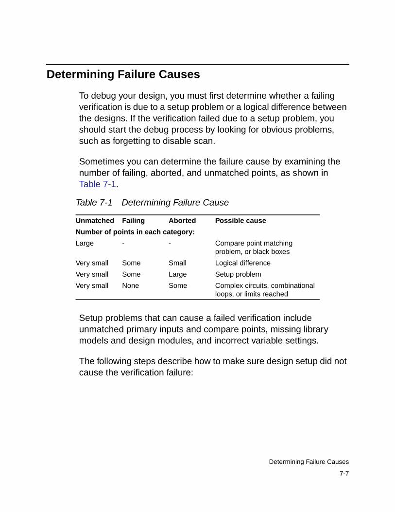
Determining Failure Causes
To debug your design, you must first determine whether a failingverification is due to a setup problem or a logical difference betweenthe designs. If the verification failed due to a setup problem, youshould start the debug process by looking for obvious problems,such as forgetting to disable scan.
Sometimes you can determine the failure cause by examining thenumber of failing, aborted, and unmatched points, as shown inTable 7-1.
Setup problems that can cause a failed verification includeunmatched primary inputs and compare points, missing librarymodels and design modules, and incorrect variable settings.
The following steps describe how to make sure design setup did notcause the verification failure:
Table 7-1 Determining Failure Cause
Unmatched Failing Aborted Possible cause
Number of points in each category:
Large - - Compare point matchingproblem, or black boxes
Very small Some Small Logical difference
Very small Some Large Setup problem
Very small None Some Complex circuits, combinationalloops, or limits reached
7-7
Determining Failure Causes
If you determine that your design contains setup errors, skip to“Eliminating Setup Possibilities” on page 7-14 to help you fix them.You must fix setup problems and then reverify the implementationdesign before debugging any problems caused by logical differencesbetween the designs.
1. If you automatically matched compare points with the verifycommand, look at the unmatched-points report by specifying thereport_unmatched_points command in fm_shell orchoosing Match > Unmatched in the GUI. The report showsmatched design objects (such as inputs) as well as matchedcompare points; use the filtering options included with thecommand to view only the unmatched compare points.
Use the iterative compare point matching technique described in“Matching Compare Points” on page 6-3 to resolve theunmatched points.
A likely consequence of an unmatched compare point (especiallya register) is that downstream compare points fail due to theirunmatched inputs.
2. Specify the report_black_boxes command in fm_shell or atthe GUI’s Formality prompt to check for unmatched black boxes.During verification, Formality treats comparable black boxes asequivalent objects. However, to be considered equivalent, a blackbox in the implementation design must map one to one with ablack box in the reference design. In general, use black boxmodels for large macrocells (such as RAMs and microprocessorcores) or when you are running a bottom-up verification.
Note:
Black boxes that do not match one to one result in unmatchedcompare points.
7-8
Chapter 7: Debugging Failed Design Verifications
For information about handling black boxes in your design, see“Working With Black Boxes” on page 5-15.
3. Check for incorrect environment variable settings, especially forthe design transformations listed in “Design Transformations” onpage 7-28. To view a list of current variable settings, use theprintvar command.
Debugging by Using Diagnosis
At this point, you have fixed all setup problems in your design ordetermined that no setup problems exist. Consequently, the failureoccurred because Formality found functional differences betweenthe implementation and reference designs. Use the following stepsto isolate the problem. This section assumes you are working in theGUI. For more information about the Formality verification anddebugging processes, see Chapter 2, “Quick Start With Formality.”
After you have run verification, debug your design by doing thefollowing:
1. From the Debug tab, click the Failing Points tab to view the failingpoints.
2. Run diagnosis on all of the failing points listed in this window byclicking Diagnose.
Note:
After clicking Diagnose, you might get a warning (FM-417)stating that too many distinct errors caused diagnosis to fail (ifthe number of distinct errors exceeds five). If this occurs, andyou have already verified that no setup problems exist, tryselecting a group of failing points (such as a group of buses
7-9
Debugging by Using Diagnosis
with common names), and click Diagnose Selected Points. Ifthe group diagnosis also fails, select a single failing point andrun selected diagnosis.
After the diagnosis is complete, the Error Candidate windowdisplays a list of error candidates. An error candidate can havemultiple distinct errors associated with it. For each error, thenumber of related failing points is reported. There can bealternate error candidates apart from the recommended onesshown in this window.
3. Inspect the alternate candidates by using Next and Previous. Youcan reissue the error candidate report anytime after runningdiagnosis by using the report_error_candidates Tclcommand.
4. Select an error with the maximum number of failing points.Right-click that error, then choose View Logic Cones. If there aremultiple failing points, a list appears from which you can select aparticular failing point to view. Errors are the drivers in the designwhose function can be changed to fix the failing compare point.
The schematic shows the error highlighted in the implementationdesign along with the associated matching region of thereference design.
Examine the logic cone for the driver causing the failure. Theproblem driver is highlighted in orange. You can select the IsolateError Candidates Pruning Mode option to view the error region inisolation. You can also prune the associated matching region ofthe reference design. To undo the pruning mode, choose Edit >Undo. For more information about pruning, see “Pruning Logic”on page 7-43.
7-10
Chapter 7: Debugging Failed Design Verifications
Note:You can employ the previous diagnosis method by setting thediagnosis_enable_error_isolation variable to false andthen rerunning verification.
Debugging by Using Logic Cones
You want to debug the failing point that shows the design differenceas quickly and easily as possible. Start with the primary outputs. Youknow that the designs are equivalent at primary outputs, whereasinternal points could have different logic cones due to changes suchas boundary optimization or retiming. Pick the smallest cone todebug. Look for a point that is not part of a vector.
You can open a logic cone view of a failing compare point to help youdebug design nonequivalencies. Use the following techniques todebug failing points in your design from the logic cone view:
1. To show the entire set of failing input patterns, click the ShowPatterns toolbar option in the logic cone window.
A pattern view window appears. Click the number above acolumn to view the pattern in the logic cone view. For eachpattern applied to the inputs, Formality displays logic values oneach pin of every instance in the logic cone.
Check the logic cone for unmatched inputs. Look for unmatchedinputs in the columns in both the reference and implementationdesigns. For example, if you see two adjacent unmatched coneinputs (one in the references and one in the implementationdesign) that have opposite values on all patterns, theseunmatched cone inputs should probably be matched.
7-11
Debugging by Using Logic Cones
Alternatively, you can also specify thereport_unmatched_points compare_point command atthe Formality prompt, or check the pattern view window for inputsthat appear in one design but not the other.
There are two types of unmatched inputs:
- Unmatched in cone
This input is not matched to any input in the correspondingcone for the other design. The logic for this cone might befunctionally different. The point might have been matchedincorrectly.
- Globally unmatched
This input is not matched to any input anywhere in the otherdesign. The point might need to be matched usingname-matching techniques. The point might represent extralogic that is in one design but not in the other.
Unmatched inputs indicate a possible setup problem notpreviously fixed. For more information about fixing problems, see“Eliminating Setup Possibilities” on page 7-14. If you change thesetup, you must reverify the implementation design beforecontinuing the debugging process.
For more information about failing input patterns and the patternview window, see “Working With Failing Patterns” on page 7-44.
2. Bring up a logic cone view of your design.
A pattern view window appears. Click the number above acolumn to view the pattern in the logic cone view. For eachpattern applied to the inputs, Formality displays logic values oneach pin of every instance in the logic cone.
7-12
Chapter 7: Debugging Failed Design Verifications
For more information about displaying your design in a logiccone, see “Working With Logic Cones” on page 7-38.
3. Look for clues in the input patterns. These clues can sometimesindicate that the implementation design has undergone atransformation of some kind.
For a list of design transformations that require setup prior toverification, see “Design Transformations” on page 7-28.
4. Prune the logic cones and subcones, as needed, to better isolatethe problem.
For more information, see “Pruning Logic” on page 7-43.
After you have isolated the difference between the implementationand reference designs, change the original design using theseprocedures and reverify it.
If the problem is in the gate-level design, a one-to-onecorrespondence between the symbols in the logic cone and theinstances in the gate netlist should help you pinpoint where to makechanges in the netlist.
To further help you debug designs, click the Zoom Full toolbar optionto view a failing point in the context of the entire design. Return to theprevious view by pressing Shift-a.
7-13
Debugging by Using Logic Cones
Eliminating Setup Possibilities
As discussed in the “Determining Failure Causes” on page 7-7section, you must resolve setup problems as part of the debuggingprocess. If your design has setup problems, you should check theareas discussed in the following sections (listed in order ofimportance):
1. Black Boxes
2. Unmatched Points
3. Design Transformations
Black Boxes
If the evidence points to a setup problem, check for black boxes. Youcan do this by:
• Viewing the transcript
• Checking the formality.log file
• Executing report_unmatched -point_type bboxcommand
• Executing the report_black_boxes command in theFormality shell or Formality prompt from within the GUI. For moreinformation about this command, see the man pages.
For more information about black boxes, see “Working With BlackBoxes” on page 5-15.
7-14
Chapter 7: Debugging Failed Design Verifications
Unmatched Points
As described in “Debugging Unmatched Points” on page 6-8, youmight need to manually match compare points by using thetechniques described in this section. Normally, you do this during thecompare point matching process, prior to running verification.
Matching With User-Supplied Names
You can force Formality to verify two design objects by setting twocompare points to match. For example, if your reference andimplementation designs have comparable output ports with differentnames, creating a compare point match that consists of the two portsforces Formality to match the object names.
Important:Use caution when adding and removing compare points. Avoidcreating a situation where two design objects not intended toform a match are used as compare points. Understanding thedesign and using the reporting feature in Formality can help youavoid this situation.
7-15
Eliminating Setup Possibilities
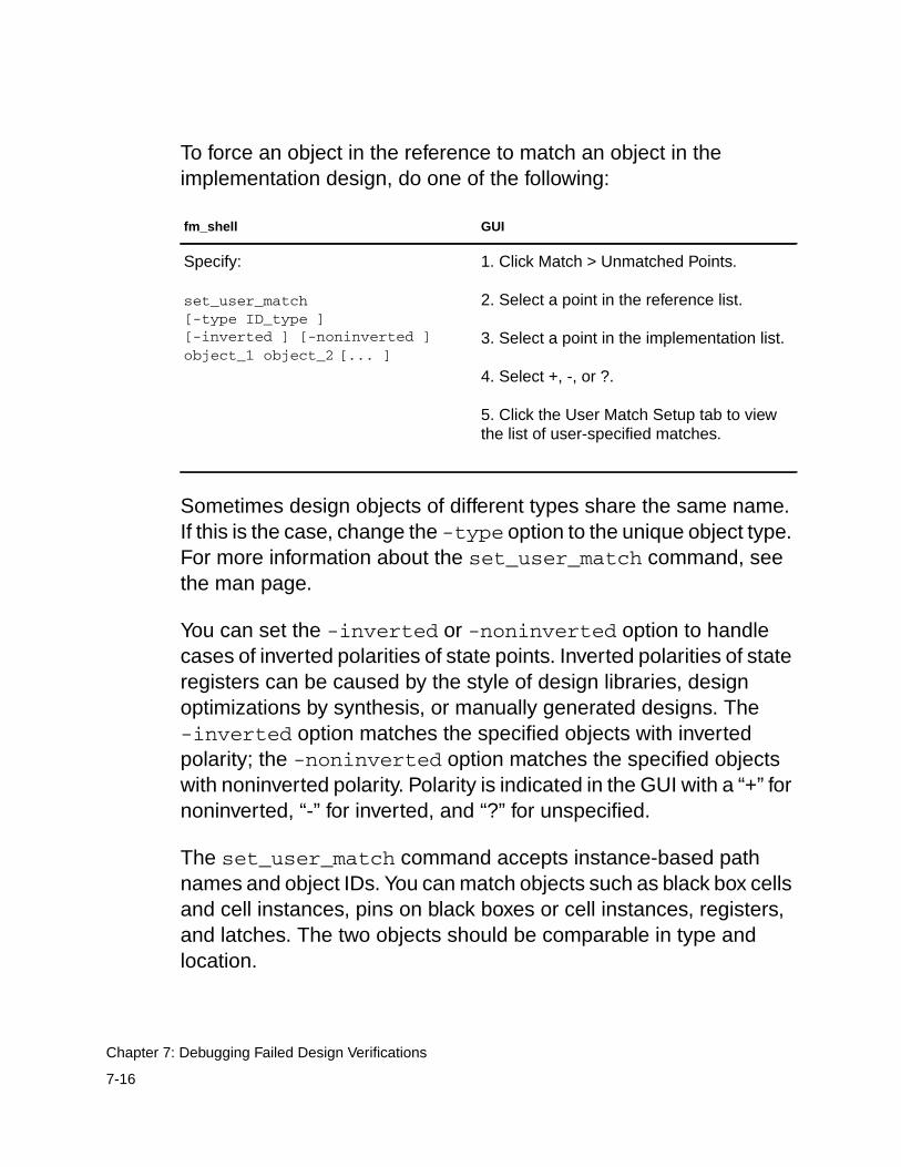
To force an object in the reference to match an object in theimplementation design, do one of the following:
Sometimes design objects of different types share the same name.If this is the case, change the -type option to the unique object type.For more information about the set_user_match command, seethe man page.
You can set the -inverted or -noninverted option to handlecases of inverted polarities of state points. Inverted polarities of stateregisters can be caused by the style of design libraries, designoptimizations by synthesis, or manually generated designs. The-inverted option matches the specified objects with invertedpolarity; the -noninverted option matches the specified objectswith noninverted polarity. Polarity is indicated in the GUI with a “+” fornoninverted, “-” for inverted, and “?” for unspecified.
The set_user_match command accepts instance-based pathnames and object IDs. You can match objects such as black box cellsand cell instances, pins on black boxes or cell instances, registers,and latches. The two objects should be comparable in type andlocation.
fm_shell GUI
Specify:
set_user_match[-type ID_type ][-inverted ] [-noninverted ]object_1 object_2 [... ]
1. Click Match > Unmatched Points.
2. Select a point in the reference list.
3. Select a point in the implementation list.
4. Select +, -, or ?.
5. Click the User Match Setup tab to viewthe list of user-specified matches.
7-16
Chapter 7: Debugging Failed Design Verifications
Along with matching individual points in comparable designs, youcan use this command to match multiple implementation objects toa single reference object (1-to-n matching). You do this by issuingset_user_match, matching each implementation object to thereference object. You cannot, however, match multiple referenceobjects to one implementation object. Doing so would cause anerror. For example, the following command sets severalimplementation objects to one reference object, datain[55]:
set_user_match $ref/CORE/RAMBLK/DRAM_64x16/I_TOP/datain[55] \
$impl/CORE/RAMBLK/DRAM_64x16/I_TOP/datain[55] \
$impl/CORE/RAMBLK/DRAM_64x16/I_TOP/datain[55]_0\
$impl/CORE/RAMBLK/DRAM_64x16/I_TOP/datain[56]_0\
$impl/CORE/RAMBLK/DRAM_64x16/I_TOP/datain[59]_0\
$impl/CORE/RAMBLK/DRAM_64x16/I_TOP/datain[60]_0
The set_user_match command allows you to match an individualpoint in a design, a useful technique if you do not see multiple similarmismatches. Note that this command does not change the names inthe database. For example, the following design objects are notmatched by the Formality name-matching algorithms:
reference:/WORK/CORE/carry_inimplementation:/WORK/CORE/cin
You can use the set_user_match command to match thesedesign objects as follows:
fm_shell (verify)> set_user_match ref:/WORK/CORE/carry_in \
7-17
Eliminating Setup Possibilities
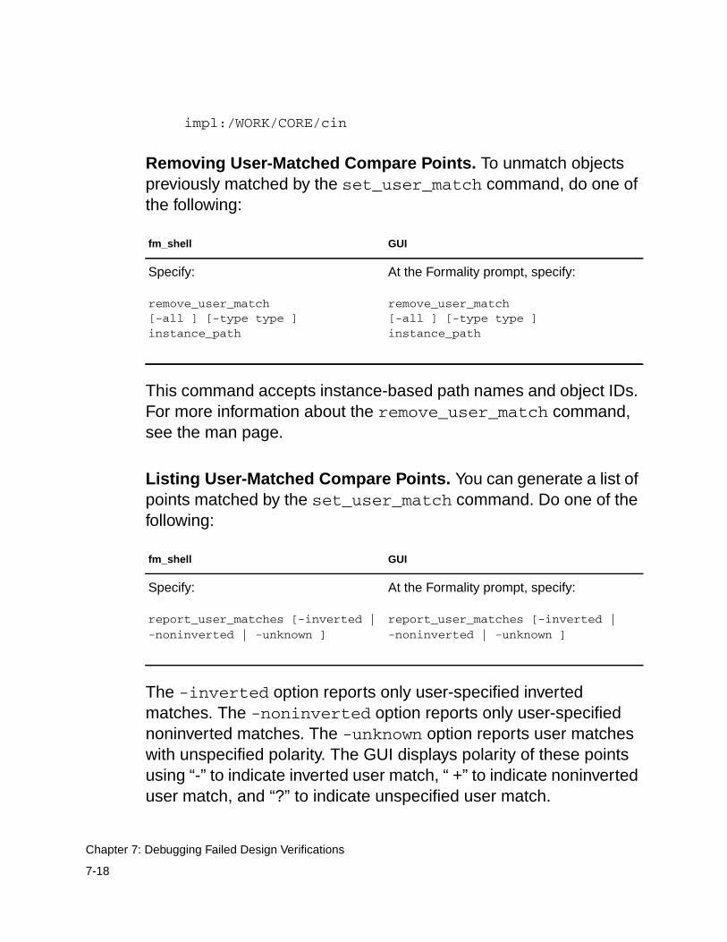
impl:/WORK/CORE/cin
Removing User-Matched Compare Points. To unmatch objectspreviously matched by the set_user_match command, do one ofthe following:
This command accepts instance-based path names and object IDs.For more information about the remove_user_match command,see the man page.
Listing User-Matched Compare Points. You can generate a list ofpoints matched by the set_user_match command. Do one of thefollowing:
The -inverted option reports only user-specified invertedmatches. The -noninverted option reports only user-specifiednoninverted matches. The -unknown option reports user matcheswith unspecified polarity. The GUI displays polarity of these pointsusing “-” to indicate inverted user match, “ +” to indicate noninverteduser match, and “?” to indicate unspecified user match.
fm_shell GUI
Specify:
remove_user_match[-all ] [-type type ]instance_path
At the Formality prompt, specify:
remove_user_match[-all ] [-type type ]instance_path
fm_shell GUI
Specify:
report_user_matches [-inverted |-noninverted | -unknown ]
At the Formality prompt, specify:
report_user_matches [-inverted |-noninverted | -unknown ]
7-18
Chapter 7: Debugging Failed Design Verifications
Matching With Compare Rules
As described in “Compare Rules” on page 1-28, compare rules areuser-defined regular expressions that Formality uses to translate thenames in one design before applying any name-matching methods.This approach is especially useful if names changed in a predictableway and many compare points are unmatched as a result.
Important:Because a single compare rule can map several design objectnames between the implementation and reference designs, usecaution when defining compare rules. Regular expressions withloose matching criteria can affect many design object names.
Defining a compare rule allows you to affect many design objectsduring compare point matching. For example, suppose theimplementation design uses a register naming scheme where allregisters end in the string _r_0, while the reference design uses ascheme where all registers end in _reg. One compare rule couldsuccessfully map all register names between the two designs.
Compare rules are applied during the compare point matching stepof the verification process.
7-19
Eliminating Setup Possibilities
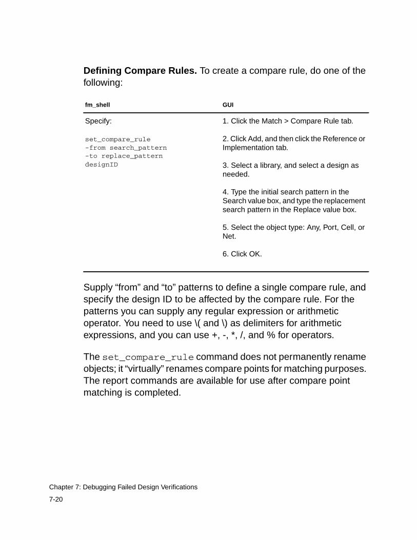
Defining Compare Rules. To create a compare rule, do one of thefollowing:
Supply “from” and “to” patterns to define a single compare rule, andspecify the design ID to be affected by the compare rule. For thepatterns you can supply any regular expression or arithmeticoperator. You need to use \( and \) as delimiters for arithmeticexpressions, and you can use +, -, *, /, and % for operators.
The set_compare_rule command does not permanently renameobjects; it “virtually” renames compare points for matching purposes.The report commands are available for use after compare pointmatching is completed.
fm_shell GUI
Specify:
set_compare_rule-from search_pattern-to replace_patterndesignID
1. Click the Match > Compare Rule tab.
2. Click Add, and then click the Reference orImplementation tab.
3. Select a library, and select a design asneeded.
4. Type the initial search pattern in theSearch value box, and type the replacementsearch pattern in the Replace value box.
5. Select the object type: Any, Port, Cell, orNet.
6. Click OK.
7-20
Chapter 7: Debugging Failed Design Verifications
Compare rules are additive in nature so they should be written insuch a way that rules do not overlap. Overlap can cause unwantedchanges to object names that can negatively affect subsequentcompare rules. The rules are applied one at a time throughout thedesign.
For example, the following registers are unmatched when twodesigns are verified:
reference:/WORK/top_mod/cntr_reg0..reference:/WORK/top_mod/cntr_reg9
implementation:/WORK/top_mod/cntr0..implementation:/WORK/top_mod/cntr9
You can use a single set_compare_rule command to match upall these points, as follows:
fm_shell (verify)> set_compare_rule ref:/WORK/top_mod \ -from {_reg\([0-9]*\)$} -to {\1}
In this example, the rule is applied on the reference design. Hence,all _reg# format object names in the reference design aretransformed to # format during compare point matching.
In the following example, assume that the registers are unmatchedwhen two designs are verified:
RTL:/WORK/P_SCHED/MC_CONTROL/FIFO_reg2[0][0]RTL:/WORK/P_SCHED/MC_CONTROL/FIFO_reg2[0][1]RTL:/WORK/P_SCHED/MC_CONTROL/FIFO_reg2[1][1]
GATE:/WORK/P_SCHED/MC_CONTROL/FIFO_reg20_0GATE:/WORK/P_SCHED/MC_CONTROL/FIFO_reg20_1
7-21
Eliminating Setup Possibilities
GATE:/WORK/P_SCHED/MC_CONTROL/FIFO_reg21_1
A single set_compare_rule matches up all these points:
fm_shell (verify)> set_compare_rule $ref \-from {_reg2\[\([0-1]\)\]\[\([0-1]\)\]$} \-to {\1_reg2\1_\2}
This rule transforms all objects in the reference design that follow theformat name_reg#[#][#] to name_reg##_#, where # is restricted toonly 0 and 1 values. This rule is applied on the reference design, butit also can be changed so that it can be applied on theimplementation design.
You can use \( and \) as delimiters for arithmetic expressions andthen use +, -, *, /, and % operators inside the delimiters tounambiguously determine them to be arithmetic operators. Forexample, to reverse a vector from the reference bus [15:0] to theimplementation bus [0:15] using an arithmetic expression, use thefollowing command:
fm_shell (verify)> set_compare_rule ref:/WORK/design_name-from {bus\[\([0-9]*\)\]} -to {bus\[\(15-\1\)\]}
The “-” operator in the replace pattern means arithmetic minus.
7-22
Chapter 7: Debugging Failed Design Verifications
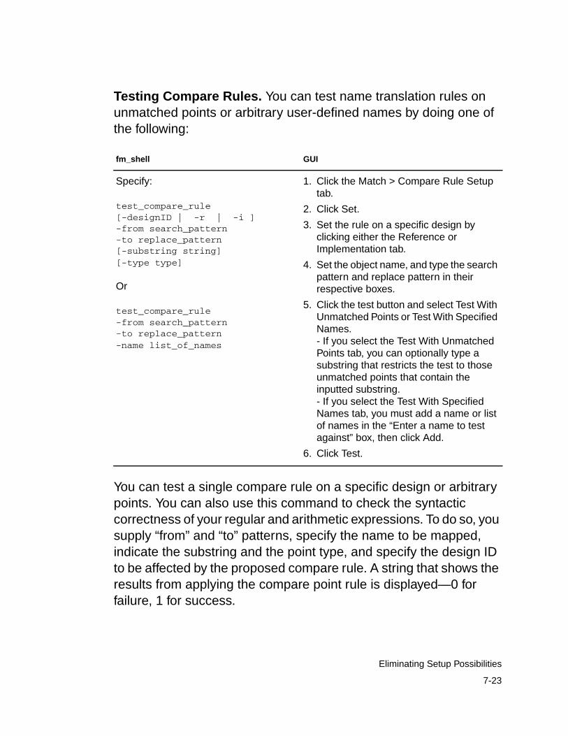
Testing Compare Rules. You can test name translation rules onunmatched points or arbitrary user-defined names by doing one ofthe following:
You can test a single compare rule on a specific design or arbitrarypoints. You can also use this command to check the syntacticcorrectness of your regular and arithmetic expressions. To do so, yousupply “from” and “to” patterns, specify the name to be mapped,indicate the substring and the point type, and specify the design IDto be affected by the proposed compare rule. A string that shows theresults from applying the compare point rule is displayed—0 forfailure, 1 for success.
fm_shell GUI
Specify:
test_compare_rule[-designID | -r | -i ]-from search_pattern-to replace_pattern[-substring string][-type type]
Or
test_compare_rule-from search_pattern-to replace_pattern-name list_of_names
1. Click the Match > Compare Rule Setuptab.
2. Click Set.
3. Set the rule on a specific design byclicking either the Reference orImplementation tab.
4. Set the object name, and type the searchpattern and replace pattern in theirrespective boxes.
5. Click the test button and select Test WithUnmatched Points or Test With SpecifiedNames.- If you select the Test With UnmatchedPoints tab, you can optionally type asubstring that restricts the test to thoseunmatched points that contain theinputted substring.- If you select the Test With SpecifiedNames tab, you must add a name or listof names in the “Enter a name to testagainst” box, then click Add.
6. Click Test.
7-23
Eliminating Setup Possibilities
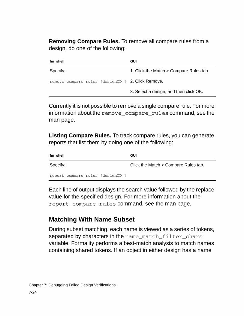
Removing Compare Rules. To remove all compare rules from adesign, do one of the following:
Currently it is not possible to remove a single compare rule. For moreinformation about the remove_compare_rules command, see theman page.
Listing Compare Rules. To track compare rules, you can generatereports that list them by doing one of the following:
Each line of output displays the search value followed by the replacevalue for the specified design. For more information about thereport_compare_rules command, see the man page.
Matching With Name Subset
During subset matching, each name is viewed as a series of tokens,separated by characters in the name_match_filter_charsvariable. Formality performs a best-match analysis to match namescontaining shared tokens. If an object in either design has a name
fm_shell GUI
Specify:
remove_compare_rules [designID ]
1. Click the Match > Compare Rules tab.
2. Click Remove.
3. Select a design, and then click OK.
fm_shell GUI
Specify:
report_compare_rules [designID ]
Click the Match > Compare Rules tab.
7-24
Chapter 7: Debugging Failed Design Verifications
that is a subset of an object name in the other design, Formality canmatch those two objects by using subset-matching algorithms. Ifmultiple potential matches are equally good, no matching occurs.
Digits are special cases, and mismatches involving digits lead to animmediate string mismatch. An exception is made if there is ahierarchy difference between the two strings and that hierarchyname contains digits.
Use the name_match_allow_subset_match variable to specifywhether to use a subset(token)-based name matching method andto specify which particular name to use. By default, the variable valueis set to strict. Strict subset matching should automatically matchmany of the uniform name changes that might otherwise require acompare rule. This is particularly helpful in designs that haveextensive, albeit fairly uniform, name changes resulting in anunreasonably high number of unmatched points for signatureanalysis to handle. The strict value ignores the delimiter charactersand alphabetic tokens that appear in at least 90 percent of all namesof a given type of object (as long as doing so does not cause namecollision issues).
If the value of the name_match_use_filter variable is false,subset matching is not performed regardless of the value of thename_match_allow_subset_match variable.
For example, the following design object pairs are matched by thesubset-matching algorithms:
7-25
Eliminating Setup Possibilities
reference:/WORK/top/stateimplementation:/WORK/top/state_reg
reference:/WORK/a/b/cimplementation:/WORK/a/c
reference:/WORK/cntr/state2/regimplementation:/WORK/cntr/reg
The following design object pairs would not be matched by thesubset-matching algorithms:
reference:/WORK/top/state_2implementation:/WORK/top/statereg_2
reference:/WORK/cntr/state_2/reg_3implementation:/WORK/cntr/state/reg[3]
The first pair fails because state is not separated from statereg witha “/” or “_”. In the second pair, the presence of digit 2 in state2 causesthe mismatch.
Renaming User-Supplied Names or Mapping File
Renaming design objects is generally used for matching primaryinput and outputs.
7-26
Chapter 7: Debugging Failed Design Verifications
To rename design objects, do one of the following:
This command permanently renames any object in the database.The new name is used by all subsequent commands and operations,including all name-matching methods. Supply a file whose formatmatches that of the report_names command in Design Compiler.For more information about the rename_object command, see theman page.
Note:To rename multiple design objects from a file, select the -fileoption. The file format should match that of the report_namescommand in Design Compiler.
The rename_object command also allows you to rename designobjects that are not verification compare points. For example, youcan use this command to rename the input ports of a design so thatthey match the input port names in the other design. Input ports mustbe matched to obtain a successful verification. This commandsupplies exact name pairs so you know the exact change that isgoing to take place.
For example, the following rename_object command renames aport called clk_in to clockin to match the primary inputs:
fm_shell GUI
Specify:
rename_object-file file_name[-type object_type ][-shared_lib ][-container container_name ][-reverse ] objectID[new_name ]
At the Formality prompt, specify:
rename_object-file file_name[-type object_type ][-shared_lib ][-container container_name ][-reverse ] objectID[new_name ]
7-27
Eliminating Setup Possibilities
fm_shell (verify)> rename_object impl:/*/am2910/clk_inclockin
You can use the rename_object command to change the name ofa hierarchical cell, possibly benefiting the automatic compare pointmatching algorithms. In addition, you can use it on primary ports tomake a verification succeed where the ports have been renamed(perhaps inadvertently).
You can also use the change_names command in Design Compilerto change the names in the gate-level netlist. However, depending onthe complexity of name changes, Formality might match thecompare points successfully when verifying two designs (one beforeand one after the use of the change_names command). To workaround this problem, obtain the changed-names report from DesignCompiler and supply it to Formality with the rename_objectcommand for compare point matching.
For example, the following rename_object command uses a file torename objects in a design:
fm_shell (verify)> rename_object -file names.rpt \-container impl -reverse
Design Transformations
Various combinational and sequential transformations can causeproblems if you do not perform the proper setup before verification.Setup requirements are discussed in Chapter 5, “Preparing theDesign for Verification,” for the following common designtransformations:
• Internal scan insertion on page 5-38.
• Boundary scan on page 5-39.
7-28
Chapter 7: Debugging Failed Design Verifications
• Clock tree buffering on page 5-41.
• Asynchronous bypass logic on page 5-43.
• Clock gating on page 5-45.
• Inversion push on page 5-50.
• Reencoded finite state machines on page 5-53.
• Retimed designs on page 5-59.
Working With Schematics
Viewing cells and other design objects in the context of the overalldesign can help you locate and understand failing areas of thedesign. This section describes how to use schematics to help youdebug failing compare points. It pertains to the GUI only.
Viewing Schematics
In any type of report window, you can view a schematic for any objectdescribed in the report. This feature lets you quickly find the area inyour design related to an item described in the report.
To generate a schematic view, do the following:
• Right-click in a design in any of the following report windows:
Verify
Match > Unmatched and Match > Unmatched
Debug > Failing Points, Debug > Passing Points, Debug >Aborted Points
7-29
Working With Schematics
• Choose View > View Reference Object or View > ViewImplementation Object.
After you perform these steps, a schematic view window appearsthat shows the selected object in the context of its parent design. Theobject is highlighted and centered in the schematic view window.
From the schematic view window you can zoom in and zoom out ofa view, print schematics, and search for objects. You can also use theschematic view window menus to move up and down through thedesign hierarchy of the design.
To change the text size in a schematic, choose View > Preferences> Increase Font Size or Decrease Font Size. Increasing ordecreasing the font size changes the menu and window text, but notthe text in the schematic. Schematic text automatically increases ordecreases as you zoom in or out.
Figure 7-3 shows a schematic view window.
7-30
Chapter 7: Debugging Failed Design Verifications
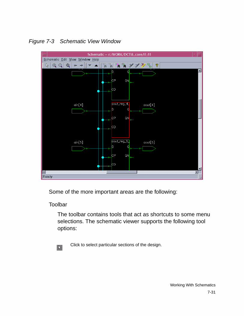
Figure 7-3 Schematic View Window
Some of the more important areas are the following:
Toolbar
The toolbar contains tools that act as shortcuts to some menuselections. The schematic viewer supports the following tooloptions:
Click to select particular sections of the design.
7-31
Working With Schematics

Click to increase the magnification applied to the schematic area byapproximately two times (2X).
Click to decrease the magnification applied to the schematic area byapproximately 2X.
Click to redraw the displayed schematic sheet so that all logic is viewable.
Click to view the previous view.
Click to view the next view.
Click to find the driver for the selected net.
Click to find the load on the selected net.
Click to find and zoom to the compare point in the schematic.
Click to display the object finder dialog box to find an object by name inthe schematic.
Click to set highlighting on the selected objects.
Click to remove highlighting from the selected objects.
Click to clear highlighting from all objects.
7-32
Chapter 7: Debugging Failed Design Verifications
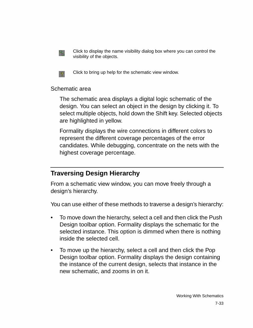
Schematic area
The schematic area displays a digital logic schematic of thedesign. You can select an object in the design by clicking it. Toselect multiple objects, hold down the Shift key. Selected objectsare highlighted in yellow.
Formality displays the wire connections in different colors torepresent the different coverage percentages of the errorcandidates. While debugging, concentrate on the nets with thehighest coverage percentage.
Traversing Design Hierarchy
From a schematic view window, you can move freely through adesign’s hierarchy.
You can use either of these methods to traverse a design’s hierarchy:
• To move down the hierarchy, select a cell and then click the PushDesign toolbar option. Formality displays the schematic for theselected instance. This option is dimmed when there is nothinginside the selected cell.
• To move up the hierarchy, select a cell and then click the PopDesign toolbar option. Formality displays the design containingthe instance of the current design, selects that instance in thenew schematic, and zooms in on it.
Click to display the name visibility dialog box where you can control thevisibility of the objects.
Click to bring up help for the schematic view window.
7-33
Working With Schematics
To retain selection of a port, pin, or net when traversing hierarchy,use the following method:
• To move down the hierarchy, select both the desired pin or netand the corresponding cell, using Control-click. Next, click thePush Design toolbar option.
• To move up the hierarchy, select a port or corresponding net, thenclick the Pop Design toolbar option.
Finding a Particular Object
To find an object in the currently displayed design, do the following:
1. In the schematic view window, choose Edit > Find by Name. Thisopens the Find By Name dialog box, which lists the objectscontained in the design.
2. In the top text box, select Cells, Ports, or Nets. Objects of theselected type are displayed in the list box, which you can scrollthrough.
3. Select an object from the list.
4. Click OK.
Formality zooms in on the object, putting it at the center of theview; the object is selected and highlighted in yellow.
7-34
Chapter 7: Debugging Failed Design Verifications
Generating a List of Objects
Using the object finder, you can interact with a schematic throughdynamic lists of drivers, loads, nets, cells, and ports. Click FindDriver, Find Load, Find X, or Find By Name on the toolbar, or choosethe corresponding item from the menu, to open the dialog box thatyou use to generate your preferred list.
For example, to get a list of loads for a net, follow these steps:
1. Click to select the desired net in your schematic.
2. On the toolbar, click Find Load.
The Object Finder dialog box appears with a list of loads for thenet you selected.
Note:
If the net has a single load and you click Find Load, the GUItakes you directly to the load without bringing up the dialogbox. This is also true when you are using Find Driver.
3. Click one of the loads from the list.
Notice that the schematic has centered on and highlighted thatcell.
You can also switch to a list of drivers from that cell by using FindDriver and selecting a driver from the list provided. Likewise, you canswitch to a list of all cells, nets, or ports, and select one of thoseinstead.
7-35
Working With Schematics
Zooming In and Out of a View
The schematic view window provides three tools that allow you toquickly size the logic in the window: Zoom In, Zoom Out, and ZoomFull.
Formality tracks each schematic view window’s display historybeginning with creation of the window. You can use the “Back toprevious view” toolbar option to step back through views and the“Forward to next view” option to return.
To display the entire design, use the Zoom Full tool. There are fourways to invoke this tool:
• Choose View > Zoom Full.
• Right-click in the schematic window and choose Zoom Full.
• Click the Zoom Full toolbar option.
• Press the letter f on the keyboard.
Similarly, to zoom in or zoom out, choose View > Zoom In Tool orZoom Out Tool, and click where you want the new view to becentered.
To repeatedly zoom into a design, do the following:
1. Place the pointer in the schematic area.
2. Press the equal sign key (=) to activate the Zoom In tool. Thepointer changes to a magnifying glass icon with a plus symbol asif you had clicked the Zoom In Tool toolbar option.
3. Place the pointer where you want to zoom in, then click.
4. Keep clicking as needed, to zoom in further.
7-36
Chapter 7: Debugging Failed Design Verifications
To repeatedly zoom out of a design, follow the same steps used tozoom into a design, except press the minus (–) key to activate theZoom Out tool.
To quickly zoom in on a small area, invoke the Zoom In tool to displaythe magnifying glass pointer. Hold down the left mouse button anddrag a box around the area of interest.
You can print the schematic from a schematic view window or areport from a report window.
To print a schematic, do the following:
1. In the schematic window, choose Schematic > Print. Make surethe schematic appears as you want it to print. You can use theZoom In and Zoom Out toolbar buttons to get different views ofthe schematic.
2. In the Setup Printer dialog box, select the print options asdesired, then click OK. If you print to a file, you are asked tospecify the file name.
After spooling the job to the printer, Formality restores theschematic view.
The procedure is the same for printing a schematic from a schematicwindow or a report from a report window. Use File > Print.
Viewing RTL Source Code
You can select an object from any schematic view (or logic coneview) and view its corresponding RTL source data. Source browsingworks with all RTL and netlist source files.
To view RTL source code, do the following:
7-37
Working With Schematics
• In the schematic, select a design object, such as a net.
• Right-click and choose View Source.
A window opens with the RTL source code. The selected object ishighlighted in red. The previous and next toolbar arrows allow you tocycle through instances of the selected object.
In addition, in any report window, you can right-click a design andthen choose View Reference Source or View ImplementationSource.
Working With Logic Cones
As described in step 2 of “Debugging by Using Logic Cones” onpage 7-11, you can open a logic cone view of a failing compare pointto help you debug design nonequivalencies.
To open a logic cone view,
1. Select a design object in a report window (passing points, failingpoints, aborted points, or verified points).
2. Right-click and choose View Logic Cones.
A logic cone window appears, as shown in Figure 7-4.
7-38
Chapter 7: Debugging Failed Design Verifications
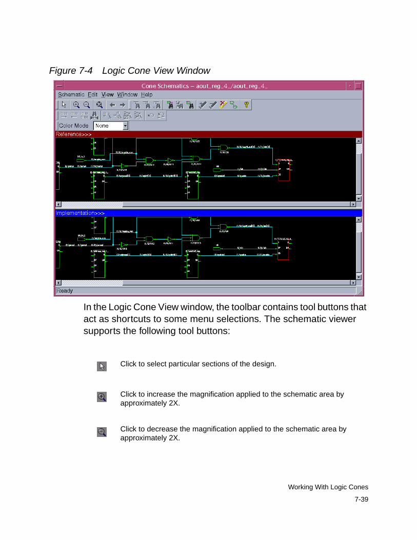
Figure 7-4 Logic Cone View Window
In the Logic Cone View window, the toolbar contains tool buttons thatact as shortcuts to some menu selections. The schematic viewersupports the following tool buttons:
Click to select particular sections of the design.
Click to increase the magnification applied to the schematic area byapproximately 2X.
Click to decrease the magnification applied to the schematic area byapproximately 2X.
7-39
Working With Logic Cones

Click to redraw the displayed schematic sheet so that all logic is viewable.
Click to view the previous view.
Click to view the next view.
Click to find the driver for the selected net.
Click to find the load on the selected net.
Click to find all net sources of the selected net with logic value X.
Click to find and zoom to the compare point in the schematic.
Click to find the point in the opposing window that matches the point youselected in a double-cone schematic.
Click to display the object finder dialog box to find an object by name inthe schematic.
Click to set highlighting on the selected objects.
Click to remove highlighting from the selected objects.
Click to clear highlighting from all objects.
7-40
Chapter 7: Debugging Failed Design Verifications
Click to display the name visibility dialog box where you can control thevisibility of the objects.
Click to bring up help for the logic cone view window.
Click to show the next pattern values on the schematic.
Click to show the previous pattern values on the schematic.
Click to open the patterns viewer window to show all patterns for thecurrent compare point.
Click to bring up the matching analysis tool for this compare point.
Click to find the point in the opposing window that matches the point youselected in a double-cone schematic.
Click to remove the subcones of the selected net.
Click to isolate the subcones of the selected net.
Click to prune logic and isolate error candidates.
Click to undo the last edit cone operation.
Click to revert to the original cone before editing operations.
7-41
Working With Logic Cones
In the Logic Cone View window, the two schematics display the logiccones, one for the reference design and one for the implementationdesign. The logic areas display object symbols, object names, objectconnections, applied states, and port names. To obtain informationabout an object in the logic area, place the mouse pointer on it.
Nets and registers highlighted in magenta denote objects set withuser-defined constants. The constant value is annotated next to theobject.
The following annotations are displayed next to failed registers:
• Failure Cause Data: One register loads a 0 while the other loadsa 1.
• Failure Cause Clock: One clock is triggered by a signal change,while the other is not.
• Failure Cause Asynch: One asynchronous reset line is high,while the other is low.
To view the logic cone schematic for an unmatched register, do thefollowing:
1. From the cone schematic window, select the unmatched coneinput register you want the schematic for.
2. Right-click to open the Context menu.
3. Choose View Logic Cones from this menu.
A single cone schematic window appears containing the cone oflogic feeding the unmatched register.
7-42
Chapter 7: Debugging Failed Design Verifications
Pruning Logic
Logic pruning reduces the complexity of a schematic so that you canbetter isolate circuitry pertinent to the failure. You generally prunelogic toward the end of the debugging process, as noted in step 4 in“Debugging by Using Diagnosis” on page 7-9.
To change the logic cone view to show only the logic that controls theoutput results, click the Remove Non-Controlling toolbar option. Thiscommand prunes away logic that does not have an effect on theoutput for the current input pattern, thus simplifying the schematic foranalysis.
To better find differences in the full schematic, remove thenon-controlling logic from the reference or implementation schematicand keep the full view in the other schematic.
To restore the full logic cone view, click the “Undo last cone edit” or“Revert to original” toolbar option, as applicable. The Undo buttonundoes the last change, while the Revert button restores the originallogic cone view.
Sometimes it is useful to look at part of a logic cone. Within Formality,a part of a cone is called a subcone. When you view logic in the logicarea, you might be interested only in a particular subcone. You canremove and restore individual subcones in the display area.
To remove a subcone, do the following:
1. In the schematic window, click the net from which you want thesubcone removed. The selected net is highlighted in yellow.
2. Click the “Remove Subcone of selected net or pin” toolbar option.
7-43
Working With Logic Cones
Formality redraws the logic without the subcone leading up to theselected net. Click the Undo last cone edit toolbar to restore thesubcone.
To isolate a subcone, do the following:
1. Click the net whose logic cone you want to isolate. The selectednet is highlighted in yellow.
2. Click the “Isolate subcone of selected pin or net” toolbar option.
Formality redraws the logic with only the subcone of the selectednet visible.
Working With Failing Patterns
Formality keeps track of the set of input patterns, 0s and 1s only, thatcause verification and diagnosis operations to fail. From the logiccone view window, you can simulate the logic by applying singlevectors from this set.
By default, Formality uses up to 256 failing patterns to performdiagnosis. When more than one failing compare point exists,Formality selects and uses a set of failing pattern vectors from thepatterns of all failing compare points.
A pattern is automatically applied to a displayed logic cone for boththe implementation and the reference design. Formality applies thefirst pattern to both logic areas and displays the state valuesassociated with the logic cones. When the displayed pattern is nothelpful for debugging, you can experiment with other failing patterns.
7-44
Chapter 7: Debugging Failed Design Verifications
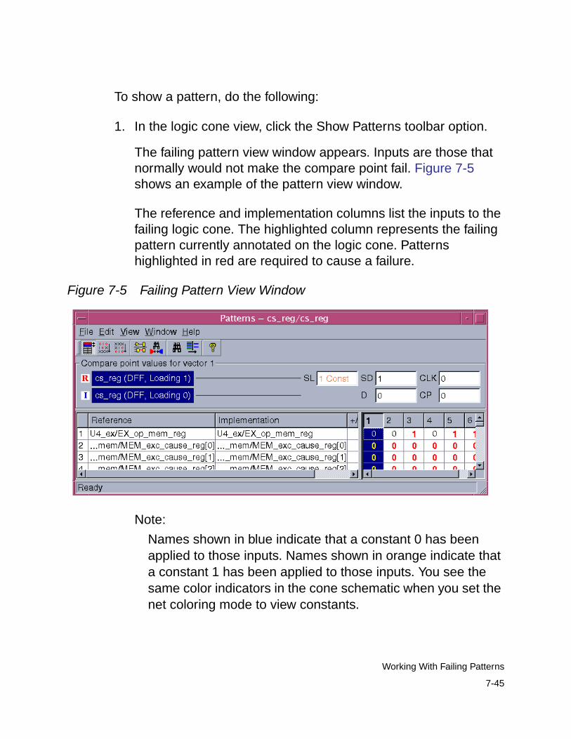
To show a pattern, do the following:
1. In the logic cone view, click the Show Patterns toolbar option.
The failing pattern view window appears. Inputs are those thatnormally would not make the compare point fail. Figure 7-5shows an example of the pattern view window.
The reference and implementation columns list the inputs to thefailing logic cone. The highlighted column represents the failingpattern currently annotated on the logic cone. Patternshighlighted in red are required to cause a failure.
Figure 7-5 Failing Pattern View Window
Note:
Names shown in blue indicate that a constant 0 has beenapplied to those inputs. Names shown in orange indicate thata constant 1 has been applied to those inputs. You see thesame color indicators in the cone schematic when you set thenet coloring mode to view constants.
7-45
Working With Failing Patterns
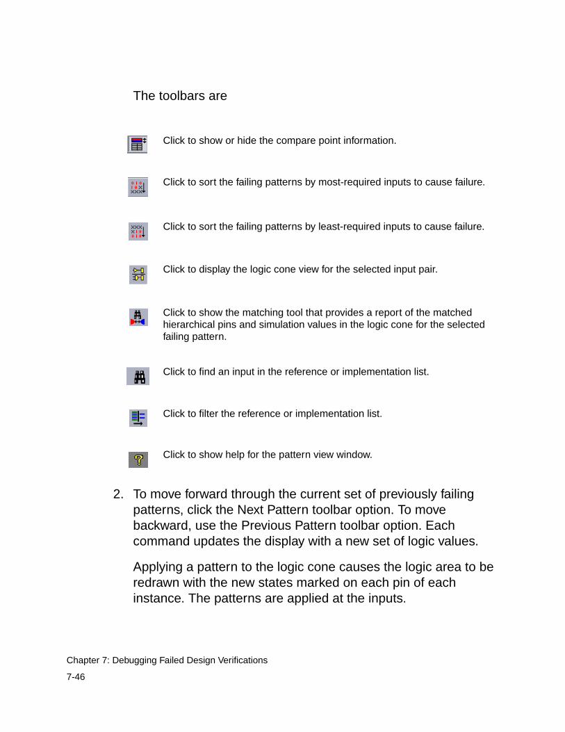
The toolbars are
2. To move forward through the current set of previously failingpatterns, click the Next Pattern toolbar option. To movebackward, use the Previous Pattern toolbar option. Eachcommand updates the display with a new set of logic values.
Applying a pattern to the logic cone causes the logic area to beredrawn with the new states marked on each pin of eachinstance. The patterns are applied at the inputs.
Click to show or hide the compare point information.
Click to sort the failing patterns by most-required inputs to cause failure.
Click to sort the failing patterns by least-required inputs to cause failure.
Click to display the logic cone view for the selected input pair.
Click to show the matching tool that provides a report of the matchedhierarchical pins and simulation values in the logic cone for the selectedfailing pattern.
Click to find an input in the reference or implementation list.
Click to filter the reference or implementation list.
Click to show help for the pattern view window.
7-46
Chapter 7: Debugging Failed Design Verifications
You can move through patterns only when the failed verification orcompleted diagnosis operation has identified more than one failingpattern for the displayed logic cone. If only one pattern exists, theNext Pattern and Previous Pattern options in the View menu areinactive (dimmed).
Saving Failing Patterns
Formality retains the set of failing patterns for the most recently failedverification. You can save these patterns for use in simulation at alater time.
To save the current set of failing patterns, do one of the following:
This command saves failing patterns to an external file (*.fpt). Formore information about this command, see the man page.
Note:Be sure that the verification section of the transcript shows thatverification failed.
fm_shell GUI
Specify:
write_failing_patterns[-diagnosis_patterns ][-verilog ] [-replace ]file_name
1. Choose File > Save Failing Patterns.
2. In the “File name” box, type the file name.
3. Select Save Diagnosis Patterns Only (tosave a diagnosis pattern subset) or SavePatterns in Verilog Format.
4. Click OK.
7-47
Working With Failing Patterns
Running Previously Saved Failing Patterns
To simulate the implementation and reference designs with a set ofpreviously saved failing patterns, do one of the following:
Note:The file containing previous failing patterns must be readable byFormality, not saved as a text file. If you save the failing patternsin Verilog format, you cannot use the resulting file with thesimulate_patterns command.
You can do two things with previously saved failing patterns:
• Simulate your top-level design by applying the entire set ofpatterns.
• Apply single patterns from the set to the design while viewing aparticular logic cone.
When you run a set of previously failing patterns, Formality performslogic simulation on the implementation and reference designs. Usingfailing patterns as input vectors can help you determine whetherchanges you have made to the implementation design have fixed aproblem found during verification.
fm_shell GUI
Specify:
simulate_patterns file
At the Formality prompt, specify:
simulate_patterns file
7-48
Chapter 7: Debugging Failed Design Verifications

After applying the patterns, Formality reports the success of thesimulation by refreshing the verification section of the informationbar. A report created at this point reflects the state of the completedsimulation; it does not reflect the state of the most recently failedverification.
Note:Passing simulation performed with a set of previously failingpatterns is not sufficient to prove design equivalence. Forfunctional equivalence to be proved, the implementation designmust pass verification.
7-49
Working With Failing Patterns

7-50
Chapter 7: Debugging Failed Design Verifications
8Technology Library Verification 8
Formality allows you to verify a reference design with animplementation design in the process described in Chapters 4through 6. However, you can also compare technology (or cell)libraries, as described in this chapter.
In this chapter it is assumed that you understand Formality conceptsand the general process for Formality design verification.
This chapter contains the following sections:
• Overview
• Initializing Library Verification
• Loading the Reference Library
• Loading the Implementation Library
• Listing the Cells
8-1
• Specifying a Customized Cell List
• Elaborating Library Cells
• Performing Library Verification
• Reporting and Interpreting Verification Results
• Debugging Failed Library Cells
For additional information about verifying libraries, see the FormalityESP User Guide in the ESP documentation suite.
8-2
Chapter 8: Technology Library Verification
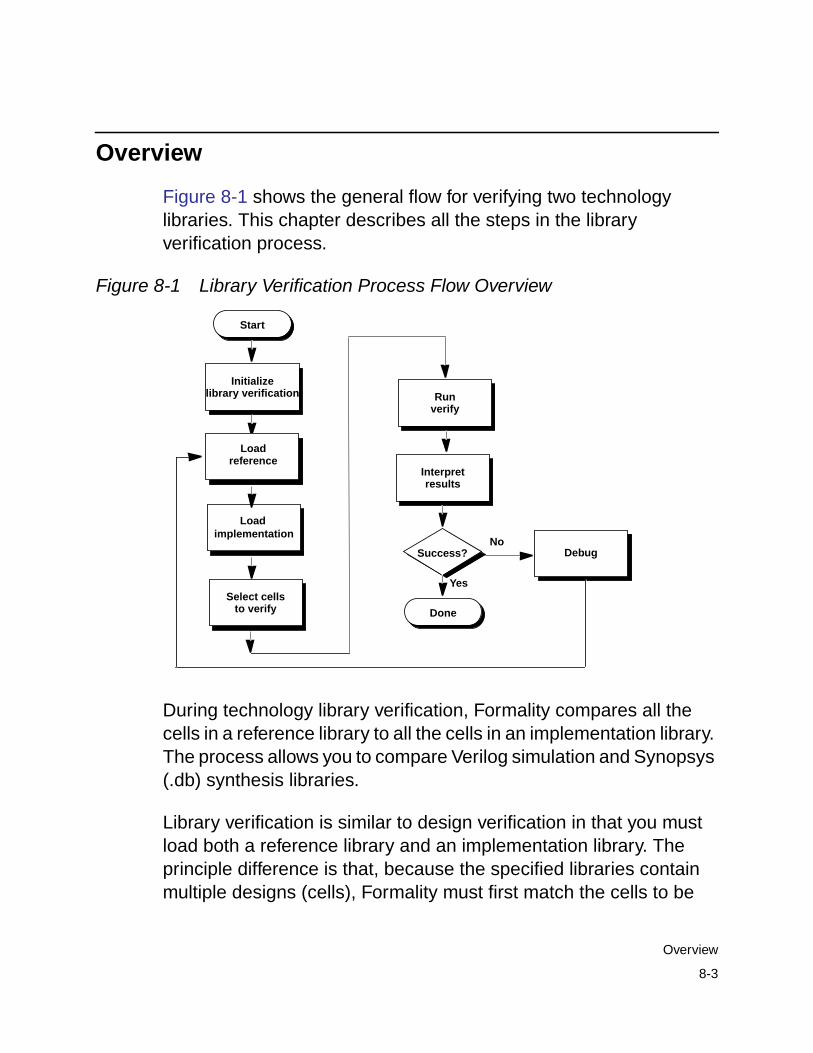
Overview
Figure 8-1 shows the general flow for verifying two technologylibraries. This chapter describes all the steps in the libraryverification process.
Figure 8-1 Library Verification Process Flow Overview
During technology library verification, Formality compares all thecells in a reference library to all the cells in an implementation library.The process allows you to compare Verilog simulation and Synopsys(.db) synthesis libraries.
Library verification is similar to design verification in that you mustload both a reference library and an implementation library. Theprinciple difference is that, because the specified libraries containmultiple designs (cells), Formality must first match the cells to be
Start
Interpretresults
Runverify
Success?No
Yes
Done
Initialize
Select cells
Loadreference
Debug
implementation
library verification
to verify
Load
8-3
Overview
verified from each library. This matching occurs when you load thereference and implementation designs. Formality then performscompare point matching and verification one cell-pair at a time.
The Formality add-on tool, Formality ESP, extends the functionalequivalence checking provided by Formality. For more informationabout functional equivalence for full-custom transistor-level memorymacros, datapath macros, and library cells, see the Formality ESPUser Guide.
Initializing Library Verification
To verify two libraries, you must first switch to thelibrary_verification mode (as opposed to setup, match,verify, or debug mode). The GUI closes if it is running. Libraryverification is a command-line-driven process. Each time you enter(or leave) library verification mode, Formality empties the contents ofthe r and i containers in readiness for a new library (or design)verification session.
To enter library verification mode, specify thelibrary_verification command, as follows:
fm_shell (setup)> library_verification argument
The fm_shell prompt changes to
fm_shell (library_setup)>
You can specify one of the following options for argument:
• verilog_verilog
• db_db
8-4
Chapter 8: Technology Library Verification
• verilog_db
• db_verilog
• none
The first design type in the preceding examples defines thereference library; the second type defines the implementation library.If you specify none, Formality returns to setup mode.
When you set this mode, Formality sets the following variable:
set verification_passing_mode "equality"
When you exit library verification mode, Formality sets the variableback to its default value, "consistency".
Note:Unsupported synthesis library formats must be translated byLibrary Compiler before being read into Formality.
Loading the Reference Library
As with the design verification process described in Chapter 4, youmust specify the reference library prior to the implementation library.
To specify the reference library, use one of the following readcommands, depending on the library format:
fm_shell (library_setup)> read_db -r file_listfm_shell (library_setup)> read_verilog -r [-tech] file_list
8-5
Loading the Reference Library
As described in the man pages, the read_db and read_verilogcommands have several options that do not apply to libraryverification. Use the read_verilog -tech option if you have aUDP file.
Formality loads the reference library into the r container. You cannotrename this container.
In the Formality shell, you represent the design hierarchy by using adesignID argument. The designID argument is a path namewhose elements indicate the container (r or i), library, and designname.
Unlike with the design verification process, you do not specify theset_top command because multiple top cells are available.
Loading the Implementation Library
Specify the implementation library in the same manner as describedin the previous section, with the exception of the -r argument.Instead, use the -i argument as follows:
fm_shell (library_setup)> read_db -i file_listfm_shell (library_setup)> read_verilog -i [-tech] file_list
Formality loads the reference library into the i container. You cannotrename this container.
After you read in the implementation library, Formality performs cellmatching to generate the list of cells that are verified. Cells and portsmust match by name. The cell list consists of single cell names, andeach cell on it is expected to be found in the reference library. If not,it is a nonmatching cell and remains unverified.
8-6
Chapter 8: Technology Library Verification
Listing the Cells
By default, Formality verifies all library cells that match by name. Youcan query the default cell list prior to verification to confirm thematched and unmatched cells.
Specify the following command to return a list of library cells:
fm_shell (library_setup)> report_cell_list -reference | \-implementation | -verify | -matched | -unmatched | \-filter wildcard
You must specify one of the following options:
• -reference: Returns the cells contained in the referencelibrary.
• -implementation: Returns the cells contained in theimplementation library.
• -verify: Returns the current list of cells to be verified, whichcould differ from the default cell list if you specified theselect_cell_list command. For more information, see“Specifying a Customized Cell List” on page 8-8.
• -matched: Returns a list of reference and implementation cellsthat match by name.
• -unmatched: Returns the names of cells that did not match inthe reference and implementation containers. This option isdynamic depending on the select_cell_list commandspecification.
• -filter wildcard: Filters the report to include cells thatmatch the specified wildcard. Always specify this option inconjunction with one of the preceding options.
8-7
Listing the Cells
In the rare case that the libraries contain no matching cells, do thefollowing:
1. Return to setup mode by entering thelibrary_verification none command.
2. Edit the cell names so they match.
3. Return to library verification mode by entering thelibrary_verification mode command.
4. Reload the updated library by using the applicable readcommand.
Specifying a Customized Cell List
When you load the libraries with the read_ commands, Formalityelaborates all matched cells in preparation for verification. Afterreporting the matched cells with the report_cell_listcommand, you can refine the default cell list as necessary.
To customize the default cell list, specify the following command:
fm_shell (library_setup)> select_cell_list [-filefilename]\
[-add cell_names] [-clear] [-remove cell_names]cell_names
You can use the following options as needed:
• -file filename: Specifies a file that contains a list of cells tobe verified.
• -add cell_names: Adds the specified cells to the cell list.
• -clear: Clears the cell list.
8-8
Chapter 8: Technology Library Verification
• -remove cell_names: Removes the specified cells from thecell list.
This command supports wildcards for cell names. Enclose lists ofcells in braces. For example,
fm_shell (library_setup)> select_cell_list {AND5 OR2 JFKLP}fm_shell (library_setup)> select_cell_list ra*
As part of the debugging process, use this command to specify onlythose cells that previously failed verification.
Elaborating Library Cells
Formality automatically elaborates your library cells when runningthe verify command. You might want to elaborate your library cellsprior to verification to apply constraints to specific cells. To elaboratethese library cells, run the elaborate_library_cellscommand.
If you do not want to apply constraints to individual library cells,proceed directly to verification. For more information about using theelaborate_library_cells command, see the man page.
Performing Library Verification
Proceed to verification after optionally refining your cell list. As withthe design verification process, specify the verify command:
fm_shell (library_setup)> verify
8-9
Elaborating Library Cells
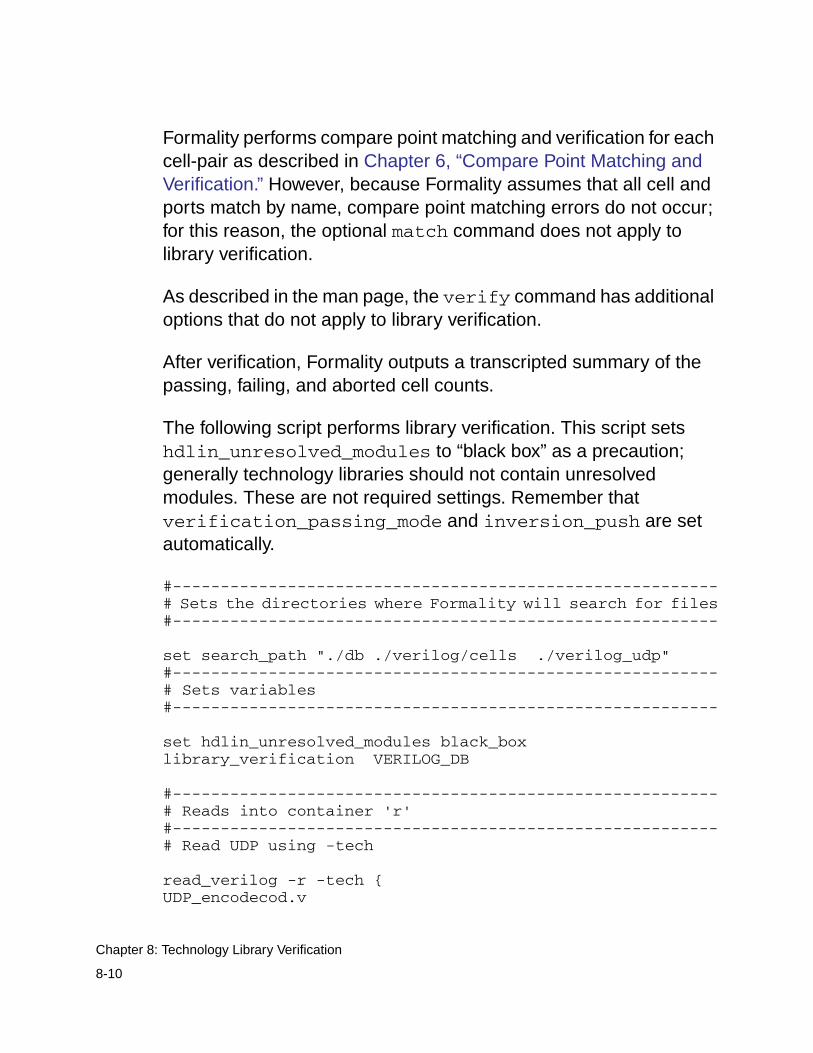
Formality performs compare point matching and verification for eachcell-pair as described in Chapter 6, “Compare Point Matching andVerification.” However, because Formality assumes that all cell andports match by name, compare point matching errors do not occur;for this reason, the optional match command does not apply tolibrary verification.
As described in the man page, the verify command has additionaloptions that do not apply to library verification.
After verification, Formality outputs a transcripted summary of thepassing, failing, and aborted cell counts.
The following script performs library verification. This script setshdlin_unresolved_modules to “black box” as a precaution;generally technology libraries should not contain unresolvedmodules. These are not required settings. Remember thatverification_passing_mode and inversion_push are setautomatically.
#---------------------------------------------------------# Sets the directories where Formality will search for files#---------------------------------------------------------
set search_path "./db ./verilog/cells ./verilog_udp"#---------------------------------------------------------# Sets variables#---------------------------------------------------------
set hdlin_unresolved_modules black_boxlibrary_verification VERILOG_DB
#---------------------------------------------------------# Reads into container 'r'#---------------------------------------------------------# Read UDP using -tech
read_verilog -r -tech {UDP_encodecod.v
8-10
Chapter 8: Technology Library Verification
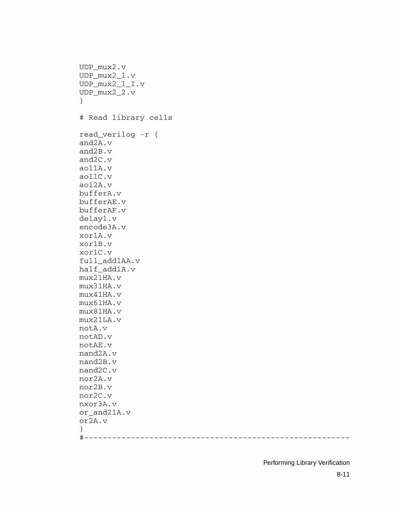
UDP_mux2.vUDP_mux2_1.vUDP_mux2_1_I.vUDP_mux2_2.v}
# Read library cells
read_verilog -r {and2A.vand2B.vand2C.vao11A.vao11C.vao12A.vbufferA.vbufferAE.vbufferAF.vdelay1.vencode3A.vxor1A.vxor1B.vxor1C.vfull_add1AA.vhalf_add1A.vmux21HA.vmux31HA.vmux41HA.vmux61HA.vmux81HA.vmux21LA.vnotA.vnotAD.vnotAE.vnand2A.vnand2B.vnand2C.vnor2A.vnor2B.vnor2C.vnxor3A.vor_and21A.vor2A.v}#---------------------------------------------------------
8-11
Performing Library Verification
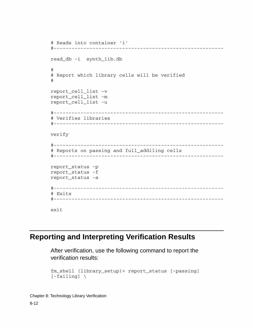
# Reads into container 'i'#---------------------------------------------------------
read_db -i synth_lib.db
## Report which library cells will be verified#
report_cell_list -vreport_cell_list -mreport_cell_list -u
#---------------------------------------------------------# Verifies libraries#---------------------------------------------------------
verify
#---------------------------------------------------------# Reports on passing and full_addiling cells#---------------------------------------------------------
report_status -preport_status -freport_status -a
#---------------------------------------------------------# Exits#---------------------------------------------------------
exit
Reporting and Interpreting Verification Results
After verification, use the following command to report theverification results:
fm_shell (library_setup)> report_status [-passing][-failing] \
8-12
Chapter 8: Technology Library Verification
[-aborting]
If you specify no arguments, Formality reports the passing, failing,and aborted cell counts. Use the options as follows:
• -passing: Returns a list of all passing cells.
• -failing: Returns a list of all failing cells.
• -aborting: Returns a list of all aborted cells.
During verification, Formality assigns one of three types of statusmessages for each library cell-pair it identifies:
Passing
A passing library cell-pair is one in which all its compare pointsare functionally equivalent.
Failing
A failing library cell-pair is one in which at least one comparepoint is not functionally equivalent.
Aborted
Verification stops. This occurs most often when Formalityreaches a user-defined failing limit. For example, Formality haltsverification on a cell after 20 failing points have been found in thecell.
In addition, any cells that fail elaboration are aborted, and a cellcan be aborted if Formality cannot determine whether one of itscompare points passes or fails. Aborted points can occur whenFormality is interrupted during the verification process.
8-13
Reporting and Interpreting Verification Results
Debugging Failed Library Cells
Use the following procedure to debug failed library cells:
1. Choose a failing cell from the status report and specify thefollowing command:
fm_shell (library_setup)> debug_library_cell cell_name
Formality reports the failing cells but retains the electrical dataonly from the last cell verified (which could be a passing cell).This command repopulates Formality with the verification datafor the specified cell, which then enables you to debug the cellfrom within the same session. You can specify the name of onlyone unique cell.
2. Specify the following command to view the failed cell’s logic:
fm_shell (library_setup)> report_truth_table signal \[-fanin signal_list] [-constraint signal_list=[0|1]
] \[-display_fanin] [-nb_lines number] \[-max_line length]
This command generates a Boolean logic truth table that you canuse to check the failed cell’s output signals. Often, this issufficient information to fix the failed cell. Use the arguments asfollows:
- signal: Specifies the signal you want to check. For example,specify the path name as follows: r:/lib/NAND/z
- -fanin signal_list: Filters the truth table for the specifiedfanin signals, where the list is enclosed in braces ({ }).
8-14
Chapter 8: Technology Library Verification
- -constraint signal_list=[0|1]: Applies the specifiedconstraint value (0 or 1) at the input and displays the outputvalues on the truth table.
- -display_fanin: Returns the fanin signals for the specifiedsignal.
- -nb_lines number: Specifies the maximum number of linesallowed for the truth table.
- -max_line length: Specifies the maximum length for eachtable line.
After fixing the cell, you can reverify it by customizing the cell listto include only the fixed cell and then specifying the verifycommand.
3. If further investigation is required to fix a failed cell, specify thefollowing command:
fm_shell (library_setup)> write_library_debug_scripts \[-dir filename]
This command generates individual Tcl scripts for each failed celland places them in the DEBUG directory unless you specify the-dir option. The DEBUG directory is located in the currentworking directory.
If you attempt to view library cells in the Formality GUI, you seeonly a black box. As shown in the following example, the Tclscripts direct Formality to treat the library cells as designs andperform traditional verification. You can then investigate thefailure results with the Formality GUI.
## --This is a run script generated by Formality libraryverification mode --set verification_passing_mode Equalityset verification_inversion_push true
8-15
Debugging Failed Library Cells
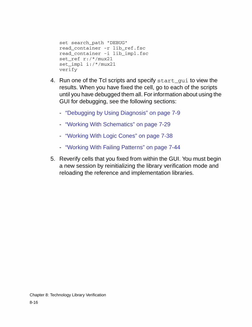
set search_path "DEBUG"read_container -r lib_ref.fscread_container -i lib_impl.fscset_ref r:/*/mux21set_impl i:/*/mux21verify
4. Run one of the Tcl scripts and specify start_gui to view theresults. When you have fixed the cell, go to each of the scriptsuntil you have debugged them all. For information about using theGUI for debugging, see the following sections:
- “Debugging by Using Diagnosis” on page 7-9
- “Working With Schematics” on page 7-29
- “Working With Logic Cones” on page 7-38
- “Working With Failing Patterns” on page 7-44
5. Reverify cells that you fixed from within the GUI. You must begina new session by reinitializing the library verification mode andreloading the reference and implementation libraries.
8-16
Chapter 8: Technology Library Verification
AAppendix A - Tcl Syntax as Applied toFormality Shell Commands A
This appendix describes the characteristics of Tcl syntax as appliedto Formality shell commands. For instructions about using theFormality shell, see “Formality Shell Environment” on page 3-6.
Tcl has a straightforward language syntax. Every Tcl script is aseries of commands separated by a new-line character orsemicolon. Each command consists of a command name and aseries of arguments.
This appendix includes the following sections:
• Using Application Commands
• Quoting Values
• Using Built-In Commands
A-1
• Using Procedures
• Using Lists
• Using Other Tcl Utilities
• Using Environment Variables
• Nesting Commands
• Evaluating Expressions
• Using Control Flow Commands
• Creating Procedures
A-2
Appendix A: Appendix A - Tcl Syntax as Applied to Formality Shell Commands
Using Application Commands
Application commands are specific to Formality. You can abbreviateall application command names, but you cannot abbreviate mostbuilt-in commands or procedures. Formality commands have thefollowing syntax:
command_name -option1 arg1 -option2 arg2 parg1 parg2
command_name
Names the application command.
-option1 arg1 -option2 arg2
Specifies options and their respective arguments.
parg1 parg2
Specifies positional arguments.
A-3
Using Application Commands
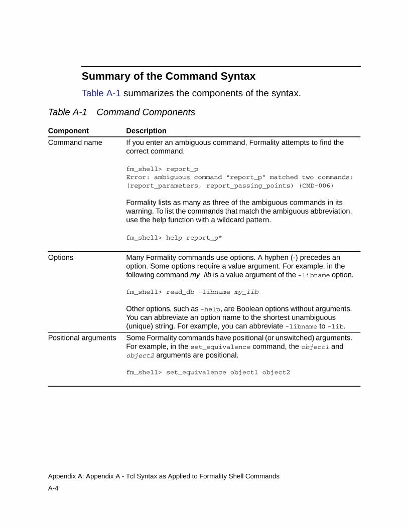
Summary of the Command Syntax
Table A-1 summarizes the components of the syntax.
Table A-1 Command Components
Component Description
Command name If you enter an ambiguous command, Formality attempts to find thecorrect command.
fm_shell> report_pError: ambiguous command “report_p” matched two commands:(report_parameters, report_passing_points) (CMD-006)
Formality lists as many as three of the ambiguous commands in itswarning. To list the commands that match the ambiguous abbreviation,use the help function with a wildcard pattern.
fm_shell> help report_p*
Options Many Formality commands use options. A hyphen (-) precedes anoption. Some options require a value argument. For example, in thefollowing command my_lib is a value argument of the -libname option.
fm_shell> read_db -libname my_lib
Other options, such as -help, are Boolean options without arguments.You can abbreviate an option name to the shortest unambiguous(unique) string. For example, you can abbreviate -libname to -lib.
Positional arguments Some Formality commands have positional (or unswitched) arguments.For example, in the set_equivalence command, the object1 andobject2 arguments are positional.
fm_shell> set_equivalence object1 object2
A-4
Appendix A: Appendix A - Tcl Syntax as Applied to Formality Shell Commands
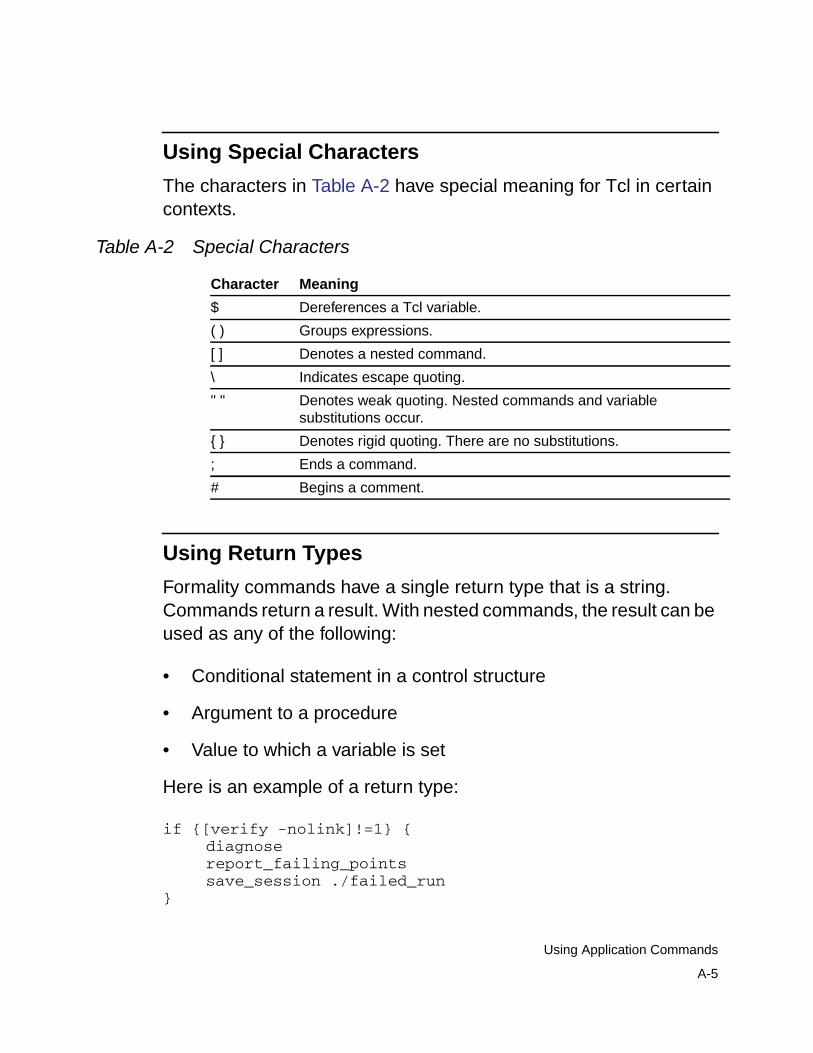
Using Special Characters
The characters in Table A-2 have special meaning for Tcl in certaincontexts.
Using Return Types
Formality commands have a single return type that is a string.Commands return a result. With nested commands, the result can beused as any of the following:
• Conditional statement in a control structure
• Argument to a procedure
• Value to which a variable is set
Here is an example of a return type:
if {[verify -nolink]!=1} {diagnosereport_failing_pointssave_session ./failed_run
}
Table A-2 Special Characters
Character Meaning
$ Dereferences a Tcl variable.
( ) Groups expressions.
[ ] Denotes a nested command.
\ Indicates escape quoting.
" " Denotes weak quoting. Nested commands and variablesubstitutions occur.
{ } Denotes rigid quoting. There are no substitutions.
; Ends a command.
# Begins a comment.
A-5
Using Application Commands
Quoting Values
You can surround values in quotation marks in several ways:
• Escape individual special characters by using the backslashcharacter (\) so that the characters are interpreted literally.
• Group a set of words separated by spaces by using doublequotation marks (“ ”). This syntax is referred to as weak quotingbecause variable, command, and backslash substitutions canoccur.
• Enclose a set of words that are separated by spaces by usingbraces ({ }). This technique is called rigid quoting. Variable,command, and backslash substitutions do not occur within rigidquoting.
The following commands are valid but yield different results.Assuming that variable a is set to 5, Formality yields the following:
fm_shell> set s "temp = data[$a]"temp = data[5]
fm_shell> set s {temp = data[$a]}temp = data[$a]
Using Built-In Commands
Most built-in commands are intrinsic to Tcl. Their arguments do notnecessarily conform to the Formality argument syntax. For example,many Tcl commands have options that do not begin with a hyphen,yet the commands use a value argument.
A-6
Appendix A: Appendix A - Tcl Syntax as Applied to Formality Shell Commands
Formality adds semantics to certain Tcl built-in commands andimposes restrictions on some elements of the language. Generally,Formality implements all of the Tcl intrinsic commands and iscompatible with them.
The Tcl string command has a compare option that is used likethis:
string compare string1 string2
Using Procedures
Formality comes with several procedures that are created throughthe /usr/synopsys/admin/setup/.synopsys_fm.setup file duringinstallation. You can see what procedures are included withFormality by entering the following command:
help
The help command returns a list of procedures, built-in commands,and application commands.
Procedures are user-defined commands that work like built-incommands. You can create your own procedures for Formality byfollowing the instructions in “Creating Procedures” on page A-16.
Procedures follow the same general syntax as applicationcommands:
command_name -option1 arg1 -option2 arg2 parg1 parg2
For a description of the syntax, see “Using Application Commands”on page A-3.
A-7
Using Procedures
Using Lists
Lists are an important part of Tcl. Lists represent collections of itemsand provide a convenient way to distribute the collections. Tcl listelements can consist of strings or other lists.
The Tcl commands you can use with lists are
• list
• concat
• join
• lappend
• lindex
• linsert
• llength
• lrange
• lreplace
• lsearch
• lsort
• split
While most publications about Tcl contain extensive discussionsabout lists and the commands that operate on lists, these Tclcommands highlight two important concepts:
A-8
Appendix A: Appendix A - Tcl Syntax as Applied to Formality Shell Commands
• Because command arguments and results are represented asstrings, lists are also represented as strings, but with a specificstructure.
• Lists are typically entered by enclosing a string in braces, asfollows:
{a b c d}
In this example, however, the string inside the braces is equivalent tothe command [list a b c d].
Note:Do not use commas to separate list items, as you do in DesignCompiler.
If you are attempting to perform command or variable substitution,the form with braces does not work. For example, this command setsthe variable a to 5.
fm_shell> set a 55
These next two commands yield different results because thecommand surrounded by braces does not expand the variable,whereas the command surrounded by square brackets (the secondcommand) does.
fm_shell> set b {c d $a [list $a z]}c d $a [list $a z]
fm_shell> set b [list c d $a [list $a z]]c d 5 {5 z}
Lists can be nested, as shown in the previous example. You can usethe concat command (or other Tcl commands) to concatenate lists.
A-9
Using Lists
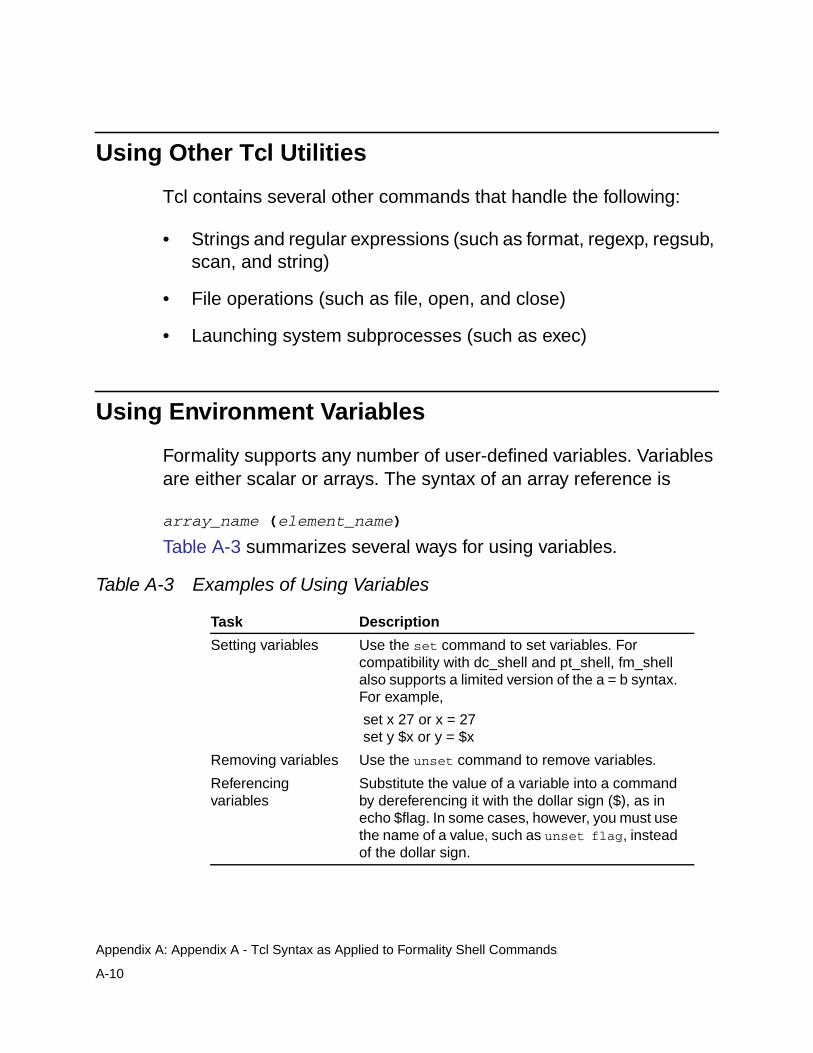
Using Other Tcl Utilities
Tcl contains several other commands that handle the following:
• Strings and regular expressions (such as format, regexp, regsub,scan, and string)
• File operations (such as file, open, and close)
• Launching system subprocesses (such as exec)
Using Environment Variables
Formality supports any number of user-defined variables. Variablesare either scalar or arrays. The syntax of an array reference is
array_name (element_name)
Table A-3 summarizes several ways for using variables.
Table A-3 Examples of Using Variables
Task Description
Setting variables Use the set command to set variables. Forcompatibility with dc_shell and pt_shell, fm_shellalso supports a limited version of the a = b syntax.For example,
set x 27 or x = 27 set y $x or y = $x
Removing variables Use the unset command to remove variables.
Referencingvariables
Substitute the value of a variable into a commandby dereferencing it with the dollar sign ($), as inecho $flag. In some cases, however, you must usethe name of a value, such as unset flag, insteadof the dollar sign.
A-10
Appendix A: Appendix A - Tcl Syntax as Applied to Formality Shell Commands
The following commands show how variables are set andreferenced:
fm_shell> set search_path ". /usr/synopsys/libraries". /usr/synopsys/libraries
fm_shell> adir = "/usr/local/lib"/usr/local/lib
fm_shell> set my_path "$adir $search_path"/usr/local/lib . /usr/synopsys/libraries
fm_shell> unset adir
fm_shell> unset my_path
Note:You can also set and unset environment variables in the GUI byentering them into the command bar or selecting File >Environment from the console window.
Nesting Commands
You can nest commands within other commands (also known ascommand substitution) by enclosing the nested commands withinsquare brackets ([ ]). Tcl imposes a depth limit of 1,000 for commandnesting.
The following examples show different ways of nesting a command.
fm_shell> set index [lsearch [set aSort \[lsort $l1]] $aValue]
fm_shell> set title "Gone With The Wind"Gone With The Wind
fm_shell> set lc_title [string tolower $title]
A-11
Nesting Commands
gone with the wind
Formality makes one exception to the use of command nesting withsquare brackets so that it can recognize netlist objects with busreferences. Formality accepts a string, such as data[63], as a namerather than as the word data followed by the result of command 63.Without this exception, data[63] must either be rigidly quoted with theuse of braces, as in {data[63]}, or the square brackets have to beescaped, as in data\[63\].
Evaluating Expressions
Tcl supports expressions. However, the base Tcl language syntaxdoes not support arithmetic operators. Instead, the expr commandevaluates expressions.
The following examples show the right and wrong ways to useexpressions:
set a (12 * $p) ;# Wrong.set a [expr (12*$p)] ;# Right!
The expr command can also evaluate logical and relationalexpressions.
Using Control Flow Commands
Control flow commands—if, while, for, foreach, break,continue, and switch—determine the order of other commands.You can use fm_shell commands in a control flow command,including other control flow commands.
A-12
Appendix A: Appendix A - Tcl Syntax as Applied to Formality Shell Commands
The following sections briefly describe the use of the control flowcommands.
Using the if Command
An if command has a minimum of two arguments:
• An expression to evaluate
• A script to conditionally start based on the result of theexpression
You can extend the if command to contain an unlimited number ofelseif clauses and one else clause. An elseif argument to theif command requires two additional arguments: an expression anda script. An else argument requires only a script.
The following example shows the correct way to specify elseif andelse clauses:
if {$x == 0} { echo "Equal"} elseif {$x > 0} { echo "Greater"} else { echo "Less"}
In this example, notice that the else and elseif clauses appear onthe same line with the closing brace ( } ). This syntax is requiredbecause a new line indicates a new command. Thus, if the elseifclause is on a separate line, it is treated as a command, although itis not one.
A-13
Using Control Flow Commands
Using while and for Loops
The while and for commands are similar to the same constructs inthe C language.
Using while Loops
The while command has two arguments:
• An expression
• A script
The following while command prints squared values from 0 to 10:
set p 0while {$p <= 10} { echo "$p squared is: [expr $p * $p]" incr p}
Using for Loops
The for command uses four arguments:
• An initialization script
• A loop-termination expression
• An iterator script
• An actual working script
The following example shows how the while loop in the previoussection is rewritten as a for loop:
for {set p 0} {$p <= 10} {incr p} { echo "$p squared is: [expr $p * $p]"}
A-14
Appendix A: Appendix A - Tcl Syntax as Applied to Formality Shell Commands
Iterating Over a List: foreach
The foreach command is similar to the same construct in the Clanguage. This command iterates over the elements in a list. Theforeach command has three arguments:
• An iterator variable
• A list
• A script to start (the script references the iterator’s variable)
To print an array, enter
foreach el [lsort [array names a]] { echo "a\($el\) = $a($el)"}
To search in the search path for several files and then report whetheror not the files are directories, enter
foreach f [which {t1 t2 t3}] { echo -n "File $f is " if { [file isdirectory $f] == 0 } { echo -n "NOT " } echo "a directory"}
Terminating a Loop: break and continue
The break and continue commands terminate a loop before thetermination condition has been reached. The break commandcauses the innermost loop to terminate. The continue commandcauses the current iteration of the innermost loop to terminate.
A-15
Using Control Flow Commands
Using the switch Command
The switch command is equivalent to an if tree that compares avariable with a number of values. One of a number of scripts is run,based on the value of the variable.
switch $x {a {incr t1}b {incr t2}c {incr t3}}
The switch command has other forms and several complexoptions. For more examples of the switch command, consult yourTcl documentation.
Creating Procedures
A powerful Formality function is the ability to write reusable Tclprocedures. With this function, you can extend the commandlanguage. You can write new commands that can use an unlimitednumber of arguments. The arguments can contain default values,and you can also use a varying number of arguments.
For example, the following procedure prints the contents of an array:
proc array_print {arr} { upvar $arr a foreach el [lsort [array names a]] { echo "$arr\($el) = $a($el)" }}
A-16
Appendix A: Appendix A - Tcl Syntax as Applied to Formality Shell Commands
Procedures can use any of the commands supported by Formality orother procedures you have defined. Procedures can even berecursive. Procedures can contain local variables and referencevariables outside of their scope. Arguments to procedures can bepassed by value or by reference.
The following sections provide some examples of procedures. Bookson the Tcl language offer additional information about writingprocedures.
Programming Default Values for Arguments
To set up a default value for an argument, you must locate theargument in a sublist that contains two elements: the name of theargument and the default value.
For example, the following procedure reads a favorite library bydefault, but reads a specific library if given:
proc read_lib { {lname favorite.db} } { read_db $lname}
Specifying a Varying Number of Arguments
You can specify a varying number of arguments by using the argsargument. You can enforce that at least some arguments are passedinto a procedure, then handle the remaining arguments as you seefit.
For example, to report the square of at least one number, use thefollowing procedure:
proc squares {num args} { set nlist $num
A-17
Creating Procedures

append nlist " " append nlist $args foreach n $nlist { echo "Square of $n is [expr $n*$n]" }
A-18
Appendix A: Appendix A - Tcl Syntax as Applied to Formality Shell Commands
BAppendix B - Formality Library Support B
This appendix provides information about verifying and modifyingtechnology libraries to make them suitable for Formality to performequivalence checking.
This appendix includes the following sections:
• Overview
• Supported Library Formats
• Updating Synthesis Libraries
• Library Enhancement and Generation Process
• Library Verification Process
• Library Loading Order
B-1
Overview
Formality compares two versions of a design for functionalequivalence. For this process to succeed, both versions of thedesign must have functional descriptions for all blocks of logic to beverified. These basic functions are defined by a library. The designlibraries must describe the functions of all cells that are used in adesign during the synthesis, test, and layout stages of the designflow.
If you are an ASIC vendor, you need to create technology librariesand provide different representations of these libraries to enable yourcustomers to use Synopsys tools. At a minimum, you must provide alibrary in Synopsys database (.db) format so that customers cansynthesize designs, and a Verilog library so that customers cansimulate designs with VCS.
There are some important library implementation issues to considerthat affect the usability, performance, and capacity of Formality forthe end user. This appendix provides guidelines to ensure that thebasic requirements of functional modeling are met. It describes thevarious library formats that Formality supports and tells you how todetermine whether any enhancements are required for the libraryand format you choose. It also provides suggestions to help youenhance your library, guidelines on verifying these enhancements,and information about packaging your library for proper use bycustomers.
B-2
Appendix B: Appendix B - Formality Library Support
Supported Library Formats
Formality works with the same libraries and design databases asDesign Compiler. Users of synthesis-based design flows can adoptFormality with little or no effort. Formality can also accept libraryinformation in the form of Verilog simulation libraries, synthesizableRTL, and gate-level netlists.
Synopsys Synthesis Libraries
To read cell definition information contained in Synopsys synthesislibraries (in .db format), use the read_db command. Readinginformation in this format is the fastest way to adopt Formality intoyour flow. Formality can use the same synthesis libraries that youdeliver to customers. However, some enhancements might berequired, as determined on a case-by-case basis. For informationabout such enhancements, see “Updating Synthesis Libraries” onpage B-4.
Verilog Simulation Libraries
To read cell definition information contained in Verilog simulationlibrary files, use the read_simulation_library orread_verilog -vcs -y command, also known as the Veriloglibrary reader. The library reader extracts the pertinent informationfrom the Verilog library to determine the gate-level behavior of thedesign, and generates a netlist that represents the functionality ofthe Verilog library cells.
B-3
Supported Library Formats
Synthesizable RTL
To read cell definition information from library cells modeled with asynthesizable subset Verilog or VHDL, use the read_verilog orread_vhdl command. Reading information in this form is typicallydone for an incremental library. You can model cells by using RTLdescriptions of the functional behavior and deliver such a collectionof cells to customers either as RTL source code or as .db output fromDesign Compiler.
Cells modeled with RTL can be inefficient for Formality to process,possibly causing a performance or capacity penalty. To avoid theseeffects, you can map the RTL to the GTECH technology and save theoptimized .db description.
Gate-Level Netlists
As an ASIC vendor, you have the option to provide the functionalinformation in the form of one or more gate-level netlists. You canprovide such netlists in .db, .v, or .vhd, format.
Updating Synthesis Libraries
If you choose to use a synthesis library, this section will help youdetermine whether any enhancements are required to supportFormality.
Typically, all vendor libraries have some black boxes in theirsynthesis libraries. There are two reasons for these black boxes:
• The current modeling capabilities of Library Compiler areinsufficient to capture the functional information.
B-4
Appendix B: Appendix B - Formality Library Support
• The modeling capability exists, but the library provider did notmodel some cells because some Synopsys tools do not usethese models and treat them as black boxes anyway.
These black boxes usually need to be updated for Formality becauseFormality needs functional models to perform verification of any cellsor modules that undergo any change in a design flow. However, theremight be some cells for which black box descriptions are acceptable.
To determine whether any additional work is required to supportFormality, use the flowchart shown in Figure B-1. If you determinethat cells need to be updated, use the flowchart shown in Figure B-2to identify the required enhancements.
B-5
Updating Synthesis Libraries
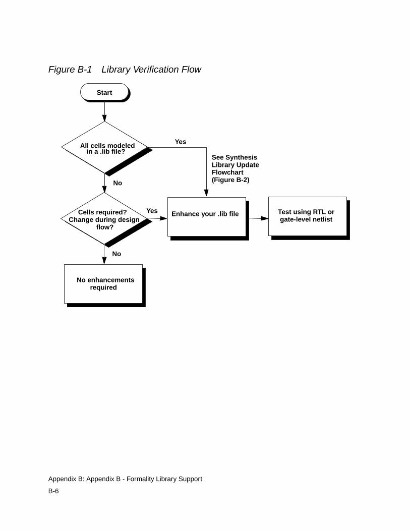
Figure B-1 Library Verification Flow
All cells modeled
Cells required?Change during design
flow?
Test using RTL orgate-level netlist
No enhancementsrequired
Start
No
Yes
No
Yes
See SynthesisLibrary UpdateFlowchart(Figure B-2)
Enhance your .lib file
in a .lib file?
B-6
Appendix B: Appendix B - Formality Library Support
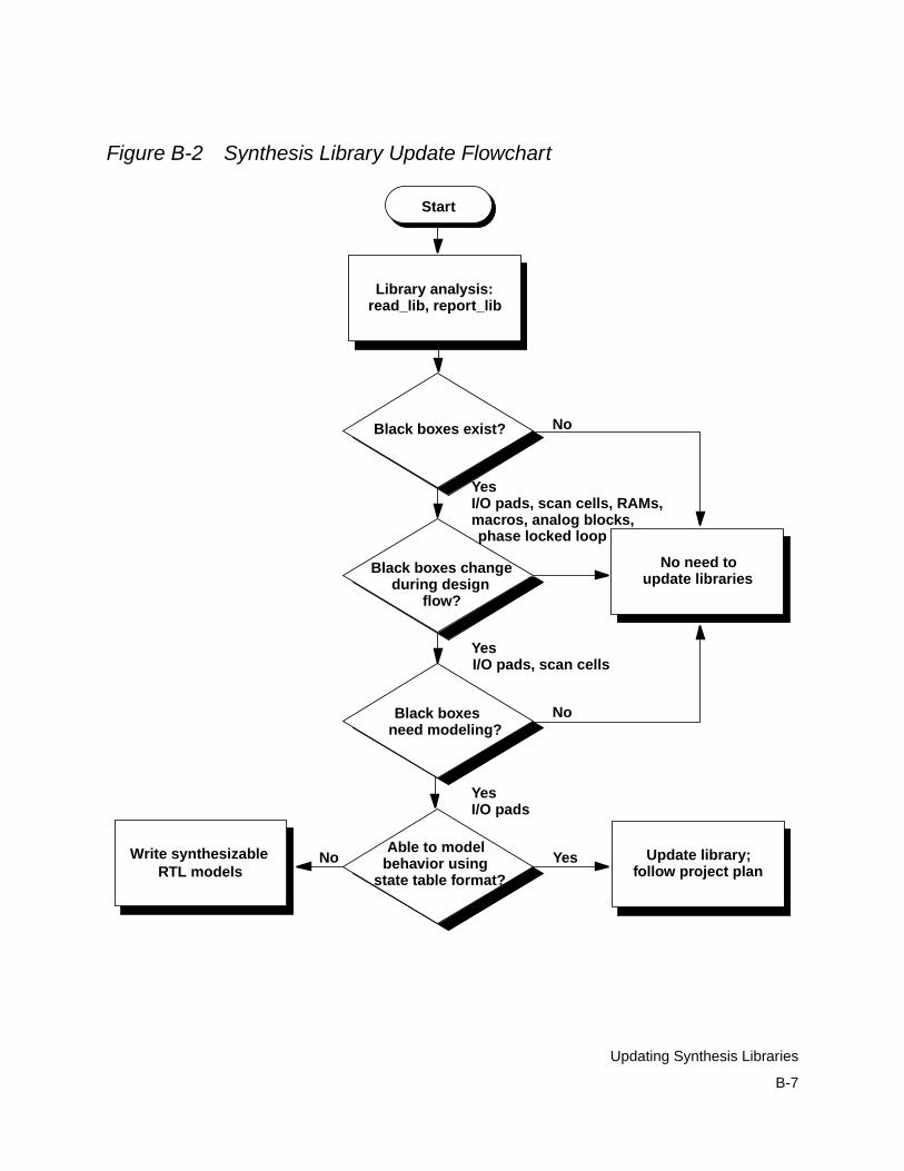
Figure B-2 Synthesis Library Update Flowchart
Black boxes exist?
Library analysis:
Start
Black boxes changeduring design
Black boxes
Able to modelbehavior using
No need to
Write synthesizable Update library;
read_lib, report_lib
flow?
update libraries
need modeling?
state table format?RTL models follow project plan
YesI/O pads, scan cells, RAMs,macros, analog blocks,
YesI/O pads, scan cells
No
No
YesI/O pads
YesNo
phase locked loop
B-7
Updating Synthesis Libraries
In Figure B-2, these are the basic steps to take to update a synthesislibrary:
1. Identify cells that do not need to be modeled to support Formality.A cell that is added by the user during the design flow andremains unchanged for the duration of the flow does not need afunctional model. Examples of this type of cell include analogcells such as phase-locked loops, analog I/O port drivers/receivers, hard macros or cores such as controllers and otherintellectual property, and highly regular structures such as RAMsand ROMs. Formality can successfully handle these cells asblack boxes.
2. Identify black box cells that need to be modeled. Most existing .dblibraries have all the important cells modeled already. Importantcells to model include registers, latches, scannable versions ofregisters and latches, all combinational cells, and I/O pad cells.The cells most likely to lack the necessary functional descriptionare the scan elements and I/O pads. Note that Formality handlessoft macro cells like any other piece of the design.
3. Identify cells that are missing in the synthesis (.db) library. If thereare cells that the tool requires and they are not present in yoursynthesis .db library, you must go through your regular librarydevelopment flow to add these cells.
Library Enhancement and Generation Process
The library enhancement and verification process depends onwhether you choose to use a synthesis (.db) library or Verilogsimulation libraries. Using a synthesis library is the preferred
B-8
Appendix B: Appendix B - Formality Library Support
method. In that case, see “Using Synthesis Libraries” on page B-9.If you choose to use Verilog simulation libraries instead, see “UsingVerilog Libraries” on page B-9.
After you generate or update the libraries, you need to verify them forfunctional accuracy as described in Chapter 8, “Technology LibraryVerification.”
Using Synthesis Libraries
If you use a synthesis library with Formality, it is necessary to definethe functionality for some cells. Most of the missing cells in a typicalsynthesis library can be modeled by using Library Compiler, whichreads an ASCII description of the cell timing and functionalcharacteristics and generates a .db file that can be read into DesignCompiler.
The “state table” format in Library Compiler is useful for modelingmany kinds of sequential cells because it provides an intuitive way todescribe complex sequential behavior. You can use this format toconvert a state table in a databook into a library cell description. TheLibrary Compiler tools reads the truth table for a cell and translatesit into a netlist. For more information, see the Library Compilerdocumentation.
Using Verilog Libraries
The read_simulation_library and read_verilog -vcs-y commands in Formality, also known as the Verilog library reader,provides a way to directly read in Verilog simulation libraries tosupport equivalence checking. It supports both gate-level anduser-defined primitive (UDP) Verilog models, but not RTL constructs.
B-9
Library Enhancement and Generation Process
To learn more about the read_simulation_library andread_verilog -vcs -y commands, use the man command inFormality. For additional information, see “Verilog Simulation Data”on page 4-18.
The read_simulation_library command has an option,-write_verilog, that is useful to silicon vendors and others whocreate technology libraries. As part of the library qualificationprocess, the silicon vendor should verify that Formality can translatethe models correctly. The -write_verilog option provides a wayto check the translation process.
Using the read_simulation_library command with the-write_verilog option reads in the Verilog simulation library andwrites out a Verilog file containing all the models that were read in.The ordering of I/O ports in the Verilog output file is compatible withthe original simulation model for all processed modules, allowing thesilicon vendor to use this file in the silicon vendor’s existing testbench to verify its correctness.
Note that Verilog written out is not the same as the Verilog read in.The command reads in the Verilog simulation models and convertsthis information into the internal Formality database. Then it convertsthis database information into Verilog and writes the results to a filecalled lib_name_fm_verilog_out.v, where lib_name is the technologylibrary name specified in the command (or the default name,TECH_WORK). Silicon vendor testing of the Verilog output file is themost complete way to verify that Formality can translate the Verilogsimulation libraries correctly.
B-10
Appendix B: Appendix B - Formality Library Support
If you are a silicon vendor using this technique, be aware that thesimulation models generated by Formality are not complete forsimulation purposes. In particular, note the following points:
• The simulation models contain no timing information. Therefore,the results from simulation test benches should not depend upondetails of the timing in the original, golden Verilog model. Forexample, be careful about changing two asynchronous controlpins at the same time.
• The simulation models accurately model the response of the cellto input conditions of logic 1, logic 0, and logic Z (whereappropriate). This meets the requirements of Formality forfunctional static verification. However, the models are notintended to exactly reproduce the handling of Xs on inputs orbidirectionals. In some cases, the models can be morepessimistic than the original, golden Verilog model in handlingsuch Xs. ASIC vendors should consider this when selecting aquality assurance (QA) testbench.
These points do not mean that Formality builds incorrect models.Formality builds models that are accurate for functional staticverification, not necessarily for simulation.
If you are a silicon vendor and you want to provide the customer withan encrypted version of the Verilog library, use the -save_binaryoption in conjunction with the -write_verilog option. Then thecommand writes the Verilog information in binary format, using thefile name lib_name_fm_verilog_out.bin. The customer can read inVerilog files saved in this format by using theread_simulation_library command. However, the-write_verilog option is disabled for this format.
B-11
Library Enhancement and Generation Process
Library Verification Process
After you decide on the library format and make any requiredenhancements, you can use any one or a combination of theverification flows described in this section. The library verificationprocess is normally a vendor-specific flow that verifies the generatedmodel against a known golden model.
The main goals of the verification process are to ensure that thegenerated functionality is accurate and complete, and to ensure thatthe generated model is understood correctly by Formality.
This section recommends generic flows that you can customize foryour specific methodology. The following recommendations areguidelines only. After you decide on a flow, you should update yourinternal test benches so that the process is automated.
The following methods are explained in this appendix:
• Verifying the synthesis (.db) libraries against the simulation (.v)libraries. This flow allows you to compare a synthesis modelversus an available simulation model. This flow also determineswhether Formality interprets a given model correctly. For moreinformation, see “Verify Synthesis and Simulation Libraries.”
• Verifying that the Verilog library reader generates the correctoutput. This flow compares the simulation results of the goldenVerilog libraries with the Verilog libraries produced by Formality.
• Verifying existing designs with the Verilog library reader.
These flows identify any problems with library support for Formality,irrespective of the library format you use.
B-12
Appendix B: Appendix B - Formality Library Support
Verify Synthesis and Simulation Libraries
This section describes a typical flow for functional verification oflibraries in Library Compiler (.db) format and Verilog library format(.v). You can use Formality for functional verification of the Veriloglibrary with the synthesis library. The flowchart shown in Figure B-3describes a typical flow for library verification.
B-13
Library Verification Process
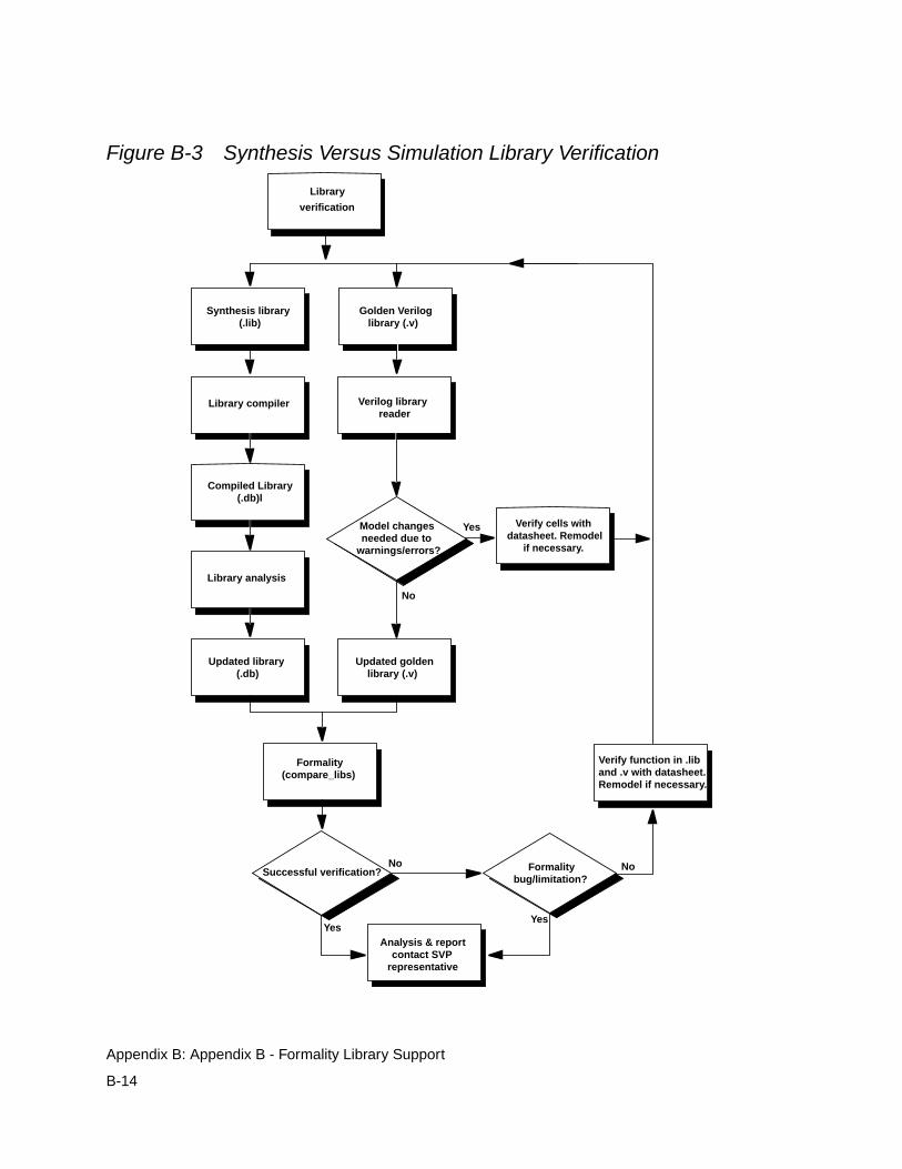
Figure B-3 Synthesis Versus Simulation Library Verification
Library
verification
Verify function in .liband .v with datasheet.Remodel if necessary.
Synthesis library(.lib)
Golden Veriloglibrary (.v)
Library compiler Verilog libraryreader
Compiled Library(.db)l
Library analysis
Updated library(.db)
Updated goldenlibrary (.v)
Formality(compare_libs)
Successful verification?
Model changesneeded due to
warnings/errors?
Analysis & reportcontact SVP
representative
Formalitybug/limitation?
Yes
No
No No
Yes
Verify cells withdatasheet. Remodel
if necessary.
Yes
B-14
Appendix B: Appendix B - Formality Library Support
The process shown in Figure B-3 can be summarized as follows:
1. Generate a synthesis database (.db) from the synthesis library(.lib).
2. Identify any problems in Verilog library (.v) generated by theVerilog library reader.
3. Use Formality to verify that the two libraries are equivalent.
Library Verification Using Formality
Before the verification process, make sure that neither thetechnology library nor the translated Verilog library haveunintentional black boxes.
You can use the library verification mode to compare the twolibraries. For information on verifying libraries and the process inwhich you run the library verification mode, see Chapter 8,“Technology Library Verification.”
Library Loading Order
Formality has the ability to load and manage multiple definitions of acell, such as synthesis .db files, simulation .db files, and Verilog/VHDL netlists. The order the library files are loaded determineswhich library model is used by Formality. If the libraries are notloaded in the correct sequence, it can lead to inconsistent orincorrect verification results.
If you are a library provider, it is recommended that you deliverexplicit Formality loading instructions for multiple libraries. One wayto do this is to provide a Formality script that loads the library files(such as .db, .v, and .vhd) in the proper order.
B-15
Library Loading Order
Single-Source Packaging
It is better to provide all the required functionality in a single source,either a synthesis (.db) or simulation (.v) file. Using a single sourcereduces support costs and maintenance requirements. However,you might choose to use multiple sources of functional information.
Multiple-Source Packaging
If you are a silicon vendor who wants to use multiple library sourcesor augment your synthesis libraries with simulation or RTLdescriptions, it is recommended that you specify the order in whichthe libraries are to be loaded.
Augmenting a Synthesis (.db) Library
If you want to use your current synthesis .db database and you donot want to update your .lib database, you can use Verilog simulationlibraries to augment the .db library. The recommended flow in thiscase is
1. Load the existing synthesis .db files.
2. Optionally load the Verilog simulation library .v files to describethe black boxes after step 1.
3. Optionally load the netlist or RTL descriptions for the black boxesafter step 2.
Augmenting a Simulation (.v) Library
If you want to use your Verilog simulation libraries and you do notwant to use your .lib-based .db database, you first need to verify thatthe Verilog library reader reads all the cells and Formality interprets
B-16
Appendix B: Appendix B - Formality Library Support
them correctly. You then need to decide whether you want to ship thetranslated .db or ship the Verilog simulation libraries. Therecommended flow in this case is
1. Load the Verilog-based .v files.
2. Optionally load synthesis-based .db files to describe the blackboxes after step 1.
3. Optionally load the netlist or RTL descriptions for black boxesafter step 2.
B-17
Library Loading Order

B-18
Appendix B: Appendix B - Formality Library Support
CAppendix C - Reference Lists C
This appendix provides reference tables that describe Formalityshell variables and commands.
This appendix includes the following sections:
• Shell Variables
• Shell Commands
C-1
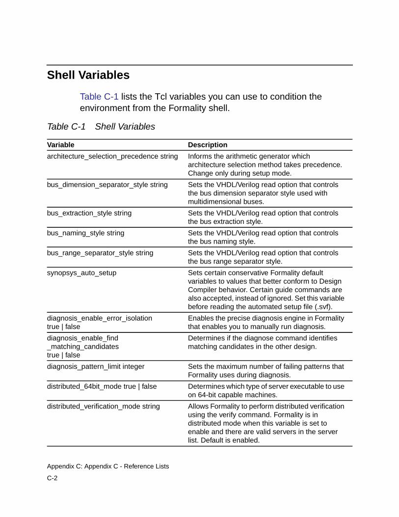
Shell Variables
Table C-1 lists the Tcl variables you can use to condition theenvironment from the Formality shell.
Table C-1 Shell Variables
Variable Description
architecture_selection_precedence string Informs the arithmetic generator whicharchitecture selection method takes precedence.Change only during setup mode.
bus_dimension_separator_style string Sets the VHDL/Verilog read option that controlsthe bus dimension separator style used withmultidimensional buses.
bus_extraction_style string Sets the VHDL/Verilog read option that controlsthe bus extraction style.
bus_naming_style string Sets the VHDL/Verilog read option that controlsthe bus naming style.
bus_range_separator_style string Sets the VHDL/Verilog read option that controlsthe bus range separator style.
synopsys_auto_setup Sets certain conservative Formality defaultvariables to values that better conform to DesignCompiler behavior. Certain guide commands arealso accepted, instead of ignored. Set this variablebefore reading the automated setup file (.svf).
diagnosis_enable_error_isolationtrue | false
Enables the precise diagnosis engine in Formalitythat enables you to manually run diagnosis.
diagnosis_enable_find_matching_candidatestrue | false
Determines if the diagnose command identifiesmatching candidates in the other design.
diagnosis_pattern_limit integer Sets the maximum number of failing patterns thatFormality uses during diagnosis.
distributed_64bit_mode true | false Determines which type of server executable to useon 64-bit capable machines.
distributed_verification_mode string Allows Formality to perform distributed verificationusing the verify command. Formality is indistributed mode when this variable is set toenable and there are valid servers in the serverlist. Default is enabled.
C-2
Appendix C: Appendix C - Reference Lists
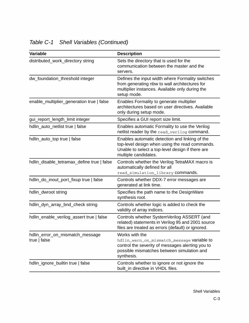
distributed_work_directory string Sets the directory that is used for thecommunication between the master and theservers.
dw_foundation_threshold integer Defines the input width where Formality switchesfrom generating nbw to wall architectures formultiplier instances. Available only during thesetup mode.
enable_multiplier_generation true | false Enables Formality to generate multiplierarchitectures based on user directives. Availableonly during setup mode.
gui_report_length_limit integer Specifies a GUI report size limit.
hdlin_auto_netlist true | false Enables automatic Formality to use the Verilognetlist reader by the read_verilog command.
hdlin_auto_top true | false Enables automatic detection and linking of thetop-level design when using the read commands.Unable to select a top-level design if there aremultiple candidates.
hdlin_disable_tetramax_define true | false Controls whether the Verilog TetraMAX macro isautomatically defined for allread_simulation_library commands.
hdlin_do_inout_port_fixup true | false Controls whether DDX-7 error messages aregenerated at link time.
hdlin_dwroot string Specifies the path name to the DesignWaresynthesis root.
hdlin_dyn_array_bnd_check string Controls whether logic is added to check thevalidity of array indices.
hdlin_enable_verilog_assert true | false Controls whether SystemVerilog ASSERT (andrelated) statements in Verilog 95 and 2001 sourcefiles are treated as errors (default) or ignored.
hdlin_error_on_mismatch_messagetrue | false
Works with thehdlin_warn_on_mismatch_message variable tocontrol the severity of messages alerting you topossible mismatches between simulation andsynthesis.
hdlin_ignore_builtin true | false Controls whether to ignore or not ignore thebuilt_in directive in VHDL files.
Table C-1 Shell Variables (Continued)
Variable Description
C-3
Shell Variables
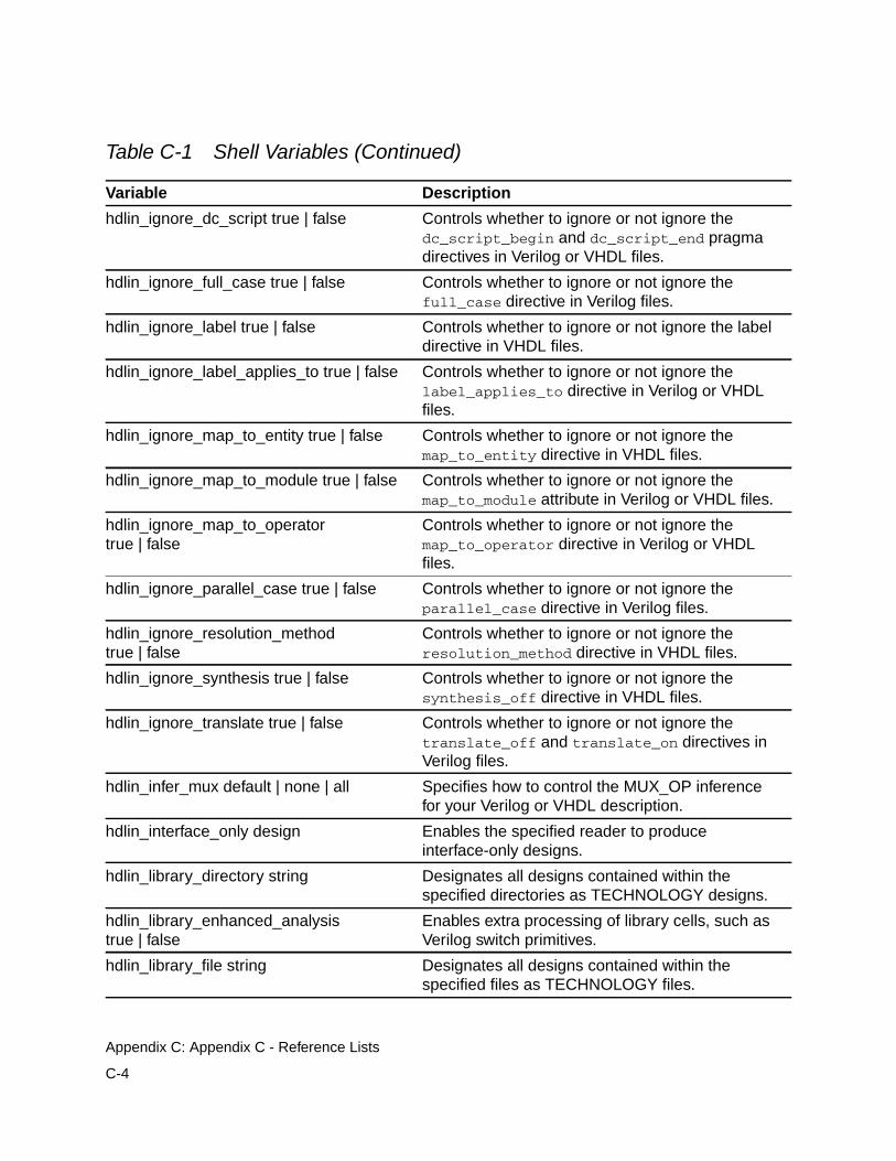
hdlin_ignore_dc_script true | false Controls whether to ignore or not ignore thedc_script_begin and dc_script_end pragmadirectives in Verilog or VHDL files.
hdlin_ignore_full_case true | false Controls whether to ignore or not ignore thefull_case directive in Verilog files.
hdlin_ignore_label true | false Controls whether to ignore or not ignore the labeldirective in VHDL files.
hdlin_ignore_label_applies_to true | false Controls whether to ignore or not ignore thelabel_applies_to directive in Verilog or VHDLfiles.
hdlin_ignore_map_to_entity true | false Controls whether to ignore or not ignore themap_to_entity directive in VHDL files.
hdlin_ignore_map_to_module true | false Controls whether to ignore or not ignore themap_to_module attribute in Verilog or VHDL files.
hdlin_ignore_map_to_operatortrue | false
Controls whether to ignore or not ignore themap_to_operator directive in Verilog or VHDLfiles.
hdlin_ignore_parallel_case true | false Controls whether to ignore or not ignore theparallel_case directive in Verilog files.
hdlin_ignore_resolution_methodtrue | false
Controls whether to ignore or not ignore theresolution_method directive in VHDL files.
hdlin_ignore_synthesis true | false Controls whether to ignore or not ignore thesynthesis_off directive in VHDL files.
hdlin_ignore_translate true | false Controls whether to ignore or not ignore thetranslate_off and translate_on directives inVerilog files.
hdlin_infer_mux default | none | all Specifies how to control the MUX_OP inferencefor your Verilog or VHDL description.
hdlin_interface_only design Enables the specified reader to produceinterface-only designs.
hdlin_library_directory string Designates all designs contained within thespecified directories as TECHNOLOGY designs.
hdlin_library_enhanced_analysistrue | false
Enables extra processing of library cells, such asVerilog switch primitives.
hdlin_library_file string Designates all designs contained within thespecified files as TECHNOLOGY files.
Table C-1 Shell Variables (Continued)
Variable Description
C-4
Appendix C: Appendix C - Reference Lists
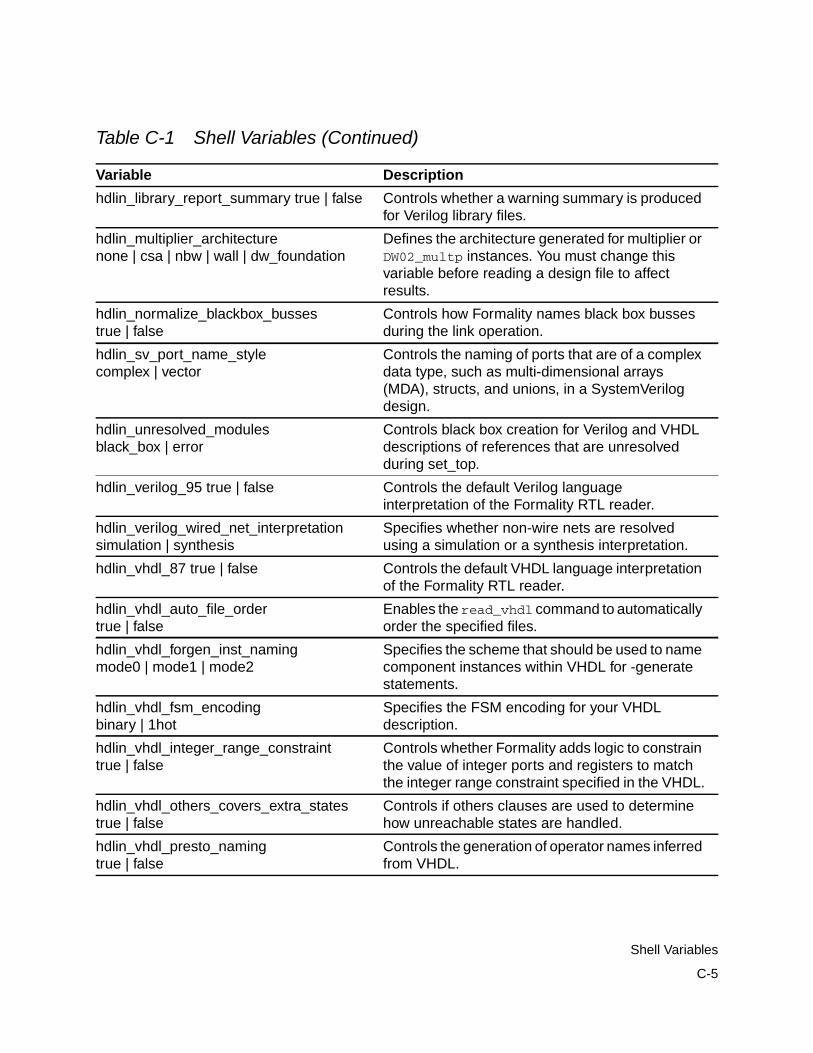
hdlin_library_report_summary true | false Controls whether a warning summary is producedfor Verilog library files.
hdlin_multiplier_architecturenone | csa | nbw | wall | dw_foundation
Defines the architecture generated for multiplier orDW02_multp instances. You must change thisvariable before reading a design file to affectresults.
hdlin_normalize_blackbox_bussestrue | false
Controls how Formality names black box bussesduring the link operation.
hdlin_sv_port_name_stylecomplex | vector
Controls the naming of ports that are of a complexdata type, such as multi-dimensional arrays(MDA), structs, and unions, in a SystemVerilogdesign.
hdlin_unresolved_modulesblack_box | error
Controls black box creation for Verilog and VHDLdescriptions of references that are unresolvedduring set_top.
hdlin_verilog_95 true | false Controls the default Verilog languageinterpretation of the Formality RTL reader.
hdlin_verilog_wired_net_interpretationsimulation | synthesis
Specifies whether non-wire nets are resolvedusing a simulation or a synthesis interpretation.
hdlin_vhdl_87 true | false Controls the default VHDL language interpretationof the Formality RTL reader.
hdlin_vhdl_auto_file_ordertrue | false
Enables the read_vhdl command to automaticallyorder the specified files.
hdlin_vhdl_forgen_inst_namingmode0 | mode1 | mode2
Specifies the scheme that should be used to namecomponent instances within VHDL for -generatestatements.
hdlin_vhdl_fsm_encodingbinary | 1hot
Specifies the FSM encoding for your VHDLdescription.
hdlin_vhdl_integer_range_constrainttrue | false
Controls whether Formality adds logic to constrainthe value of integer ports and registers to matchthe integer range constraint specified in the VHDL.
hdlin_vhdl_others_covers_extra_statestrue | false
Controls if others clauses are used to determinehow unreachable states are handled.
hdlin_vhdl_presto_namingtrue | false
Controls the generation of operator names inferredfrom VHDL.
Table C-1 Shell Variables (Continued)
Variable Description
C-5
Shell Variables
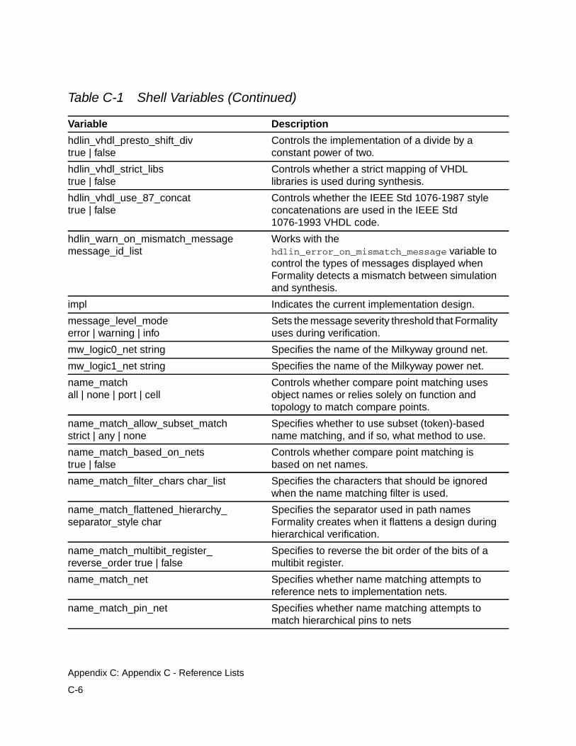
hdlin_vhdl_presto_shift_divtrue | false
Controls the implementation of a divide by aconstant power of two.
hdlin_vhdl_strict_libstrue | false
Controls whether a strict mapping of VHDLlibraries is used during synthesis.
hdlin_vhdl_use_87_concattrue | false
Controls whether the IEEE Std 1076-1987 styleconcatenations are used in the IEEE Std1076-1993 VHDL code.
hdlin_warn_on_mismatch_messagemessage_id_list
Works with thehdlin_error_on_mismatch_message variable tocontrol the types of messages displayed whenFormality detects a mismatch between simulationand synthesis.
impl Indicates the current implementation design.
message_level_modeerror | warning | info
Sets the message severity threshold that Formalityuses during verification.
mw_logic0_net string Specifies the name of the Milkyway ground net.
mw_logic1_net string Specifies the name of the Milkyway power net.
name_matchall | none | port | cell
Controls whether compare point matching usesobject names or relies solely on function andtopology to match compare points.
name_match_allow_subset_matchstrict | any | none
Specifies whether to use subset (token)-basedname matching, and if so, what method to use.
name_match_based_on_netstrue | false
Controls whether compare point matching isbased on net names.
name_match_filter_chars char_list Specifies the characters that should be ignoredwhen the name matching filter is used.
name_match_flattened_hierarchy_separator_style char
Specifies the separator used in path namesFormality creates when it flattens a design duringhierarchical verification.
name_match_multibit_register_reverse_order true | false
Specifies to reverse the bit order of the bits of amultibit register.
name_match_net Specifies whether name matching attempts toreference nets to implementation nets.
name_match_pin_net Specifies whether name matching attempts tomatch hierarchical pins to nets
Table C-1 Shell Variables (Continued)
Variable Description
C-6
Appendix C: Appendix C - Reference Lists
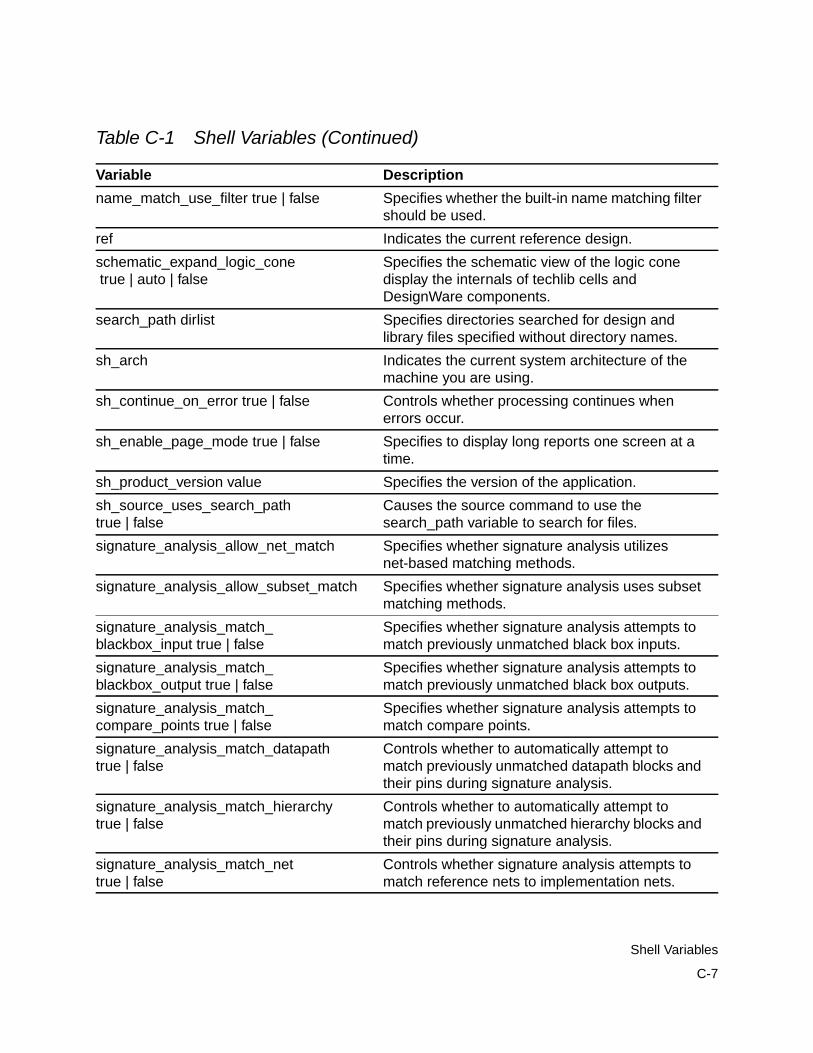
name_match_use_filter true | false Specifies whether the built-in name matching filtershould be used.
ref Indicates the current reference design.
schematic_expand_logic_cone true | auto | false
Specifies the schematic view of the logic conedisplay the internals of techlib cells andDesignWare components.
search_path dirlist Specifies directories searched for design andlibrary files specified without directory names.
sh_arch Indicates the current system architecture of themachine you are using.
sh_continue_on_error true | false Controls whether processing continues whenerrors occur.
sh_enable_page_mode true | false Specifies to display long reports one screen at atime.
sh_product_version value Specifies the version of the application.
sh_source_uses_search_pathtrue | false
Causes the source command to use thesearch_path variable to search for files.
signature_analysis_allow_net_match Specifies whether signature analysis utilizesnet-based matching methods.
signature_analysis_allow_subset_match Specifies whether signature analysis uses subsetmatching methods.
signature_analysis_match_blackbox_input true | false
Specifies whether signature analysis attempts tomatch previously unmatched black box inputs.
signature_analysis_match_blackbox_output true | false
Specifies whether signature analysis attempts tomatch previously unmatched black box outputs.
signature_analysis_match_compare_points true | false
Specifies whether signature analysis attempts tomatch compare points.
signature_analysis_match_datapathtrue | false
Controls whether to automatically attempt tomatch previously unmatched datapath blocks andtheir pins during signature analysis.
signature_analysis_match_hierarchytrue | false
Controls whether to automatically attempt tomatch previously unmatched hierarchy blocks andtheir pins during signature analysis.
signature_analysis_match_nettrue | false
Controls whether signature analysis attempts tomatch reference nets to implementation nets.
Table C-1 Shell Variables (Continued)
Variable Description
C-7
Shell Variables
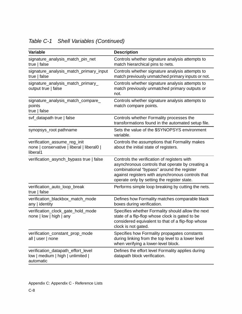
signature_analysis_match_pin_nettrue | false
Controls whether signature analysis attempts tomatch hierarchical pins to nets.
signature_analysis_match_primary_inputtrue | false
Controls whether signature analysis attempts tomatch previously unmatched primary inputs or not.
signature_analysis_match_primary_output true | false
Controls whether signature analysis attempts tomatch previously unmatched primary outputs ornot.
signature_analysis_match_compare_pointstrue | false
Controls whether signature analysis attempts tomatch compare points.
svf_datapath true | false Controls whether Formality processes thetransformations found in the automated setup file.
synopsys_root pathname Sets the value of the $SYNOPSYS environmentvariable.
verification_assume_reg_initnone | conservative | liberal | liberal0 |liberal1
Controls the assumptions that Formality makesabout the initial state of registers.
verification_asynch_bypass true | false Controls the verification of registers withasynchronous controls that operate by creating acombinational “bypass” around the registeragainst registers with asynchronous controls thatoperate only by setting the register state.
verification_auto_loop_breaktrue | false
Performs simple loop breaking by cutting the nets.
verification_blackbox_match_modeany | identity
Defines how Formality matches comparable blackboxes during verification.
verification_clock_gate_hold_modenone | low | high | any
Specifies whether Formality should allow the nextstate of a flip-flop whose clock is gated to beconsidered equivalent to that of a flip-flop whoseclock is not gated.
verification_constant_prop_modeall | user | none
Specifies how Formality propagates constantsduring linking from the top level to a lower levelwhen verifying a lower-level block.
verification_datapath_effort_levellow | medium | high | unlimited |automatic
Defines the effort level Formality applies duringdatapath block verification.
Table C-1 Shell Variables (Continued)
Variable Description
C-8
Appendix C: Appendix C - Reference Lists
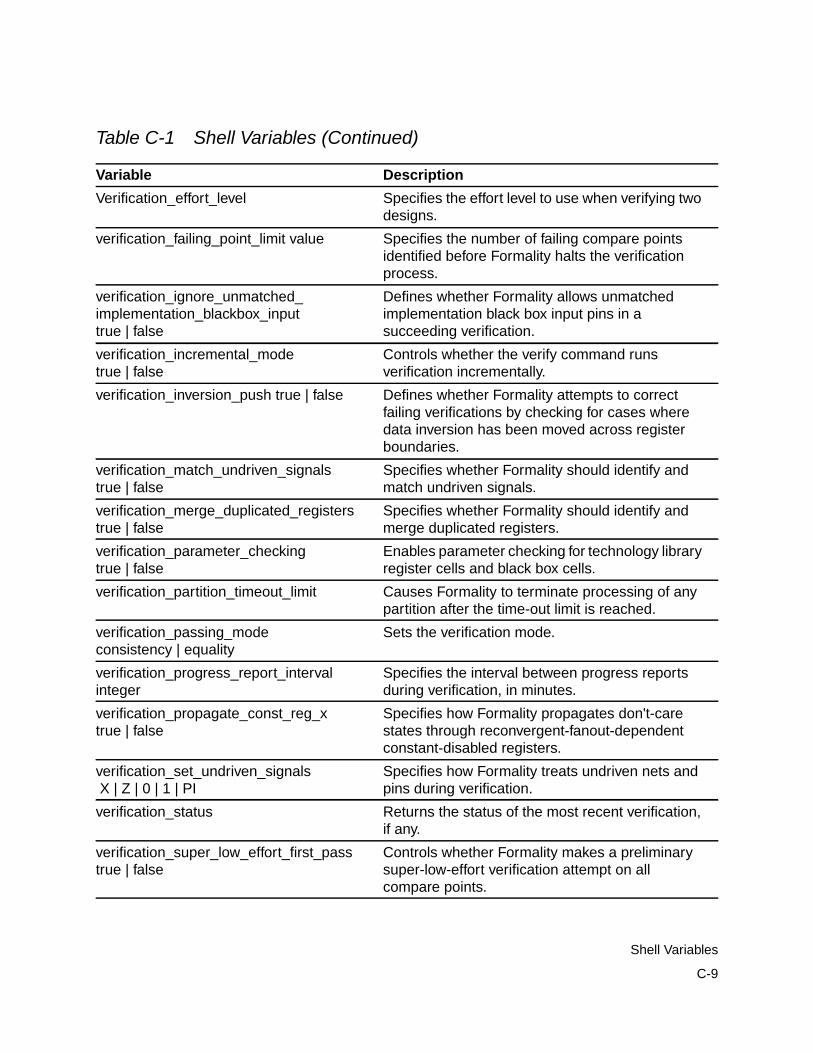
Verification_effort_level Specifies the effort level to use when verifying twodesigns.
verification_failing_point_limit value Specifies the number of failing compare pointsidentified before Formality halts the verificationprocess.
verification_ignore_unmatched_implementation_blackbox_inputtrue | false
Defines whether Formality allows unmatchedimplementation black box input pins in asucceeding verification.
verification_incremental_modetrue | false
Controls whether the verify command runsverification incrementally.
verification_inversion_push true | false Defines whether Formality attempts to correctfailing verifications by checking for cases wheredata inversion has been moved across registerboundaries.
verification_match_undriven_signalstrue | false
Specifies whether Formality should identify andmatch undriven signals.
verification_merge_duplicated_registerstrue | false
Specifies whether Formality should identify andmerge duplicated registers.
verification_parameter_checkingtrue | false
Enables parameter checking for technology libraryregister cells and black box cells.
verification_partition_timeout_limit Causes Formality to terminate processing of anypartition after the time-out limit is reached.
verification_passing_modeconsistency | equality
Sets the verification mode.
verification_progress_report_intervalinteger
Specifies the interval between progress reportsduring verification, in minutes.
verification_propagate_const_reg_xtrue | false
Specifies how Formality propagates don't-carestates through reconvergent-fanout-dependentconstant-disabled registers.
verification_set_undriven_signals X | Z | 0 | 1 | PI
Specifies how Formality treats undriven nets andpins during verification.
verification_status Returns the status of the most recent verification,if any.
verification_super_low_effort_first_passtrue | false
Controls whether Formality makes a preliminarysuper-low-effort verification attempt on allcompare points.
Table C-1 Shell Variables (Continued)
Variable Description
C-9
Shell Variables
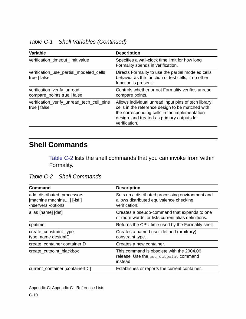
Shell Commands
Table C-2 lists the shell commands that you can invoke from withinFormality.
verification_timeout_limit value Specifies a wall-clock time limit for how longFormality spends in verification.
verification_use_partial_modeled_cellstrue | false
Directs Formality to use the partial modeled cellsbehavior as the function of test cells, if no otherfunction is present.
verification_verify_unread_compare_points true | false
Controls whether or not Formality verifies unreadcompare points.
verification_verify_unread_tech_cell_pinstrue | false
Allows individual unread input pins of tech librarycells in the reference design to be matched withthe corresponding cells in the implementationdesign. and treated as primary outputs forverification.
Table C-2 Shell Commands
Command Description
add_distributed_processors[machine machine... ] [-lsf ]-nservers -options
Sets up a distributed processing environment andallows distributed equivalence checkingverification.
alias [name] [def] Creates a pseudo-command that expands to oneor more words, or lists current alias definitions.
cputime Returns the CPU time used by the Formality shell.
create_constraint_typetype_name designID
Creates a named user-defined (arbitrary)constraint type.
create_container containerID Creates a new container.
create_cutpoint_blackbox This command is obsolete with the 2004.06release. Use the set_cutpoint commandinstead.
current_container [containerID ] Establishes or reports the current container.
Table C-1 Shell Variables (Continued)
Variable Description
C-10
Appendix C: Appendix C - Reference Lists
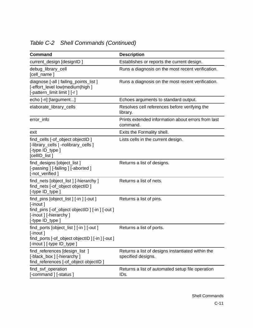
current_design [designID ] Establishes or reports the current design.
debug_library_cell[cell_name ]
Runs a diagnosis on the most recent verification.
diagnose [-all | failing_points_list ][-effort_level low|medium|high ][-pattern_limit limit ] [-r ]
Runs a diagnosis on the most recent verification.
echo [-n] [Iargument...] Echoes arguments to standard output.
elaborate_library_cells Resolves cell references before verifying thelibrary.
error_info Prints extended information about errors from lastcommand.
exit Exits the Formality shell.
find_cells [-of_object objectID ][-library_cells | -nolibrary_cells ][-type ID_type ][cellID_list ]
Lists cells in the current design.
find_designs [object_list ][-passing ] [-failing ] [-aborted ][-not_verified ]
Returns a list of designs.
find_nets [object_list ] [-hierarchy ]find_nets [-of_object objectID ][-type ID_type ]
Returns a list of nets.
find_pins [object_list ] [-in ] [-out ][-inout ]find_pins [-of_object objectID ] [-in ] [-out ][-inout ] [-hierarchy ][-type ID_type ]
Returns a list of pins.
find_ports [object_list ] [-in ] [-out ][-inout ]find_ports [-of_object objectID ] [-in ] [-out ][-inout ] [-type ID_type ]
Returns a list of ports.
find_references [design_list ][-black_box ] [-hierarchy ]find_references [-of_object objectID ]
Returns a list of designs instantiated within thespecified designs.
find_svf_operation[-command ] [-status ]
Returns a list of automated setup file operationIDs.
Table C-2 Shell Commands (Continued)
Command Description
C-11
Shell Commands
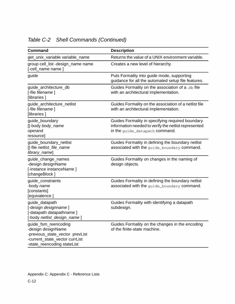
get_unix_variable variable_name Returns the value of a UNIX environment variable.
group cell_list -design_name name[-cell_name name ]
Creates a new level of hierarchy.
guide Puts Formality into guide mode, supportingguidance for all the automated setup file features.
guide_architecture_db[-file filename ][libraries ]
Guides Formality on the association of a .db filewith an architectural implementation.
guide_architecture_netlist[-file filename ][libraries ]
Guides Formality on the association of a netlist filewith an architectural implementation.
guide_boundary[[-body body_nameoperandresource]
Guides Formality in specifying required boundaryinformation needed to verify the netlist representedin the guide_datapath command.
guide_boundary_netlist[[-file netlist_file_namelibrary_name]
Guides Formality in defining the boundary netlistassociated with the guide_boundary command.
guide_change_names-design designName[-instance instanceName ][changeBlock ]
Guides Formality on changes in the naming ofdesign objects.
guide_constraints-body name[constants][equivalence ]
Guides Formality in defining the boundary netlistassociated with the guide_boundary command.
guide_datapath[-design designname ][-datapath datapathname ][-body netlist_design_name ]
Guides Formality with identifying a datapathsubdesign.
guide_fsm_reencoding-design designName-previous_state_vector prevList-current_state_vector currList-state_reencoding stateList
Guides Formality on the changes in the encodingof the finite-state machine.
Table C-2 Shell Commands (Continued)
Command Description
C-12
Appendix C: Appendix C - Reference Lists
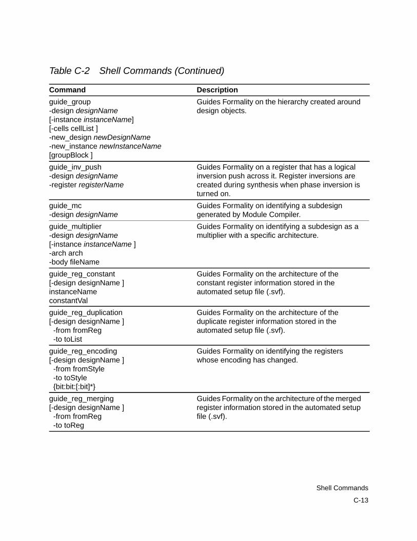
guide_group-design designName[-instance instanceName][-cells cellList ]-new_design newDesignName-new_instance newInstanceName[groupBlock ]
Guides Formality on the hierarchy created arounddesign objects.
guide_inv_push-design designName-register registerName
Guides Formality on a register that has a logicalinversion push across it. Register inversions arecreated during synthesis when phase inversion isturned on.
guide_mc-design designName
Guides Formality on identifying a subdesigngenerated by Module Compiler.
guide_multiplier-design designName[-instance instanceName ]-arch arch-body fileName
Guides Formality on identifying a subdesign as amultiplier with a specific architecture.
guide_reg_constant[-design designName ]instanceNameconstantVal
Guides Formality on the architecture of theconstant register information stored in theautomated setup file (.svf).
guide_reg_duplication[-design designName ] -from fromReg -to toList
Guides Formality on the architecture of theduplicate register information stored in theautomated setup file (.svf).
guide_reg_encoding[-design designName ] -from fromStyle -to toStyle {bit:bit:[:bit]*}
Guides Formality on identifying the registerswhose encoding has changed.
guide_reg_merging[-design designName ] -from fromReg -to toReg
Guides Formality on the architecture of the mergedregister information stored in the automated setupfile (.svf).
Table C-2 Shell Commands (Continued)
Command Description
C-13
Shell Commands
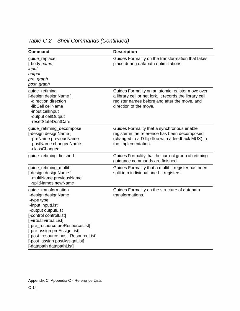
guide_replace[-body name]inputoutputpre_graphpost_graph
Guides Formality on the transformation that takesplace during datapath optimizations.
guide_retiming[-design designName ] -direction direction -libCell cellName -input cellInput -output cellOutput -resetStateDontCare
Guides Formality on an atomic register move overa library cell or net fork. It records the library cell,register names before and after the move, anddirection of the move.
guide_retiming_decompose[-design designName ] -preName previousName -postName changedName -classChanged
Guides Formality that a synchronous enableregister in the reference has been decomposed(changed to a D flip-flop with a feedback MUX) inthe implementation.
guide_retiming_finished Guides Formality that the current group of retimingguidance commands are finished.
guide_retiming_multibit[-design designName ] -multiName previousName -splitNames newName
Guides Formality that a multibit register has beensplit into individual one-bit registers.
guide_transformation -design designName -type type -input inputList -output outputList[-control controlList][-virtual virtualList][-pre_resource preResourceList][-pre-assign preAssignList][-post_resource post_ResourceList][-post_assign postAssignList][-datapath datapathList]
Guides Formality on the structure of datapathtransformations.
Table C-2 Shell Commands (Continued)
Command Description
C-14
Appendix C: Appendix C - Reference Lists
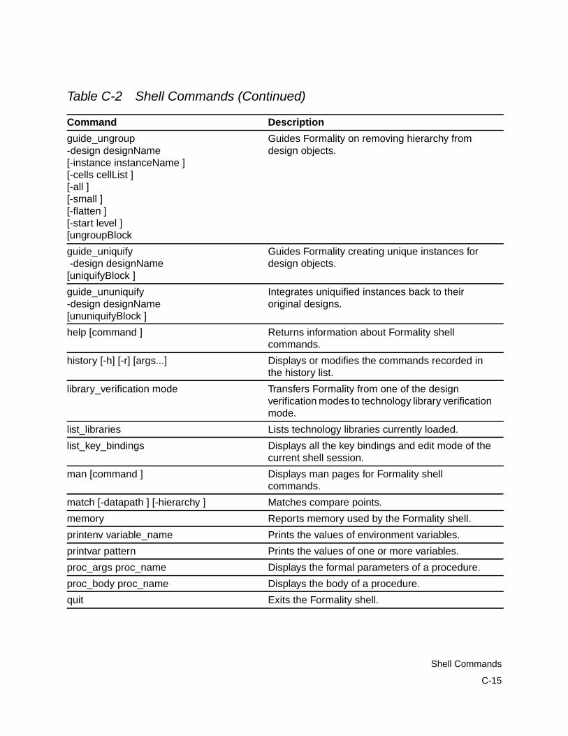
guide_ungroup-design designName[-instance instanceName ][-cells cellList ][-all ][-small ][-flatten ][-start level ][ungroupBlock
Guides Formality on removing hierarchy fromdesign objects.
guide_uniquify -design designName[uniquifyBlock ]
Guides Formality creating unique instances fordesign objects.
guide_ununiquify-design designName[ununiquifyBlock ]
Integrates uniquified instances back to theiroriginal designs.
help [command ] Returns information about Formality shellcommands.
history [-h] [-r] [args...] Displays or modifies the commands recorded inthe history list.
library_verification mode Transfers Formality from one of the designverification modes to technology library verificationmode.
list_libraries Lists technology libraries currently loaded.
list_key_bindings Displays all the key bindings and edit mode of thecurrent shell session.
man [command ] Displays man pages for Formality shellcommands.
match [-datapath ] [-hierarchy ] Matches compare points.
memory Reports memory used by the Formality shell.
printenv variable_name Prints the values of environment variables.
printvar pattern Prints the values of one or more variables.
proc_args proc_name Displays the formal parameters of a procedure.
proc_body proc_name Displays the body of a procedure.
quit Exits the Formality shell.
Table C-2 Shell Commands (Continued)
Command Description
C-15
Shell Commands
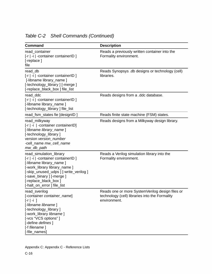
read_container[-r | -i | -container containerID ][-replace ]file
Reads a previously written container into theFormality environment.
read_db[-r | -i | -container containerID ] [-libname library_name ][-technology_library ] [-merge ][-replace_black_box ] file_list
Reads Synopsys .db designs or technology (cell)libraries.
read_ddc[-r | -i | -container containerID ][-libname library_name ][-technology_library ] file_list
Reads designs from a .ddc database.
read_fsm_states fie [designID ] Reads finite state machine (FSM) states.
read_milkyway[-r | -i | -container containerID][-libname library_name ][-technology_library ]version version_number-cell_name mw_cell_namemw_db_path
Reads designs from a Milkyway design library.
read_simulation_library[-r | -i | -container containerID ][-libname library_name ][-work_library library_name ][-skip_unused_udps ] [-write_verilog ][-save_binary ] [-merge ][-replace_black_box ][-halt_on_error ] file_list
Reads a Verilog simulation library into theFormality environment.
read_sverilog[-container container_name][-r | -i ][-libname libname ][-technology_library ][-work_library libname ][-vcs “VCS options” ][-define defines ][-f filename ][-file_names]
Reads one or more SystemVerilog design files ortechnology (cell) libraries into the Formalityenvironment.
Table C-2 Shell Commands (Continued)
Command Description
C-16
Appendix C: Appendix C - Reference Lists
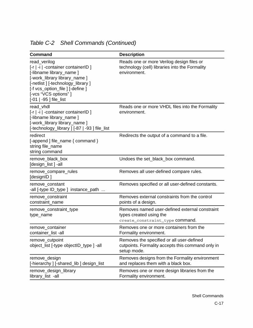
read_verilog[-r | -i | -container containerID ][-libname library_name ][-work_library library_name ][-netlist ] [-technology_library ][-f vcs_option_file ] [-define ][-vcs “VCS options” ][-01 | -95 ] file_list
Reads one or more Verilog design files ortechnology (cell) libraries into the Formalityenvironment.
read_vhdl[-r | -i | -container containerID ][-libname library_name ][-work_library library_name ][-technology_library ] [-87 | -93 ] file_list
Reads one or more VHDL files into the Formalityenvironment.
redirect[-append ] file_name { command }string file_namestring command
Redirects the output of a command to a file.
remove_black_box[design_list ] -all
Undoes the set_black_box command.
remove_compare_rules[designID ]
Removes all user-defined compare rules.
remove_constant-all [-type ID_type ] instance_path ...
Removes specified or all user-defined constants.
remove_constraintconstraint_name
Removes external constraints from the controlpoints of a design.
remove_constraint_typetype_name
Removes named user-defined external constrainttypes created using thecreate_constraint_type command.
remove_containercontainer_list -all
Removes one or more containers from theFormality environment.
remove_cutpointobject_list [-type objectID_type ] -all
Removes the specified or all user-definedcutpoints. Formality accepts this command only insetup mode.
remove_design[-hierarchy ] [-shared_lib ] design_list
Removes designs from the Formality environmentand replaces them with a black box.
remove_design_librarylibrary_list -all
Removes one or more design libraries from theFormality environment.
Table C-2 Shell Commands (Continued)
Command Description
C-17
Shell Commands
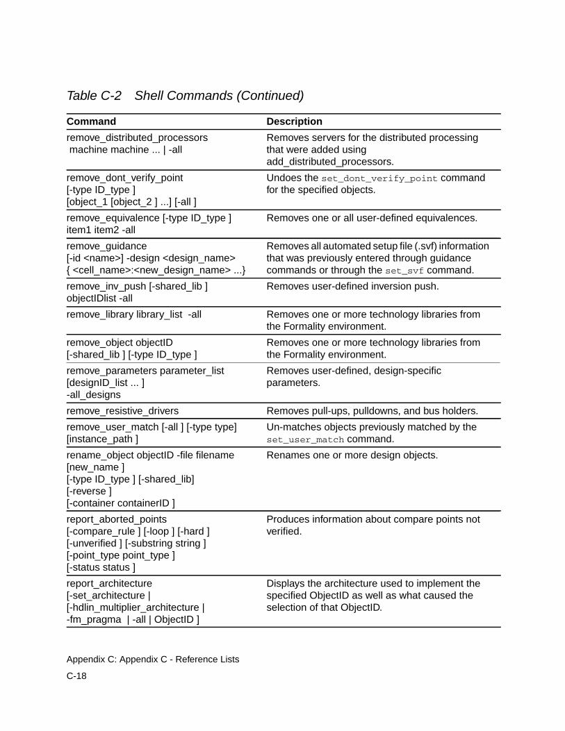
remove_distributed_processors machine machine ... | -all
Removes servers for the distributed processingthat were added usingadd_distributed_processors.
remove_dont_verify_point[-type ID_type ][object_1 [object_2 ] ...] [-all ]
Undoes the set_dont_verify_point commandfor the specified objects.
remove_equivalence [-type ID_type ]item1 item2 -all
Removes one or all user-defined equivalences.
remove_guidance[-id <name>] -design <design_name>{ <cell_name>:<new_design_name> ...}
Removes all automated setup file (.svf) informationthat was previously entered through guidancecommands or through the set_svf command.
remove_inv_push [-shared_lib ]objectIDlist -all
Removes user-defined inversion push.
remove_library library_list -all Removes one or more technology libraries fromthe Formality environment.
remove_object objectID[-shared_lib ] [-type ID_type ]
Removes one or more technology libraries fromthe Formality environment.
remove_parameters parameter_list[designID_list ... ]-all_designs
Removes user-defined, design-specificparameters.
remove_resistive_drivers Removes pull-ups, pulldowns, and bus holders.
remove_user_match [-all ] [-type type][instance_path ]
Un-matches objects previously matched by theset_user_match command.
rename_object objectID -file filename[new_name ][-type ID_type ] [-shared_lib][-reverse ][-container containerID ]
Renames one or more design objects.
report_aborted_points[-compare_rule ] [-loop ] [-hard ][-unverified ] [-substring string ][-point_type point_type ][-status status ]
Produces information about compare points notverified.
report_architecture[-set_architecture |[-hdlin_multiplier_architecture |-fm_pragma | -all | ObjectID ]
Displays the architecture used to implement thespecified ObjectID as well as what caused theselection of that ObjectID.
Table C-2 Shell Commands (Continued)
Command Description
C-18
Appendix C: Appendix C - Reference Lists
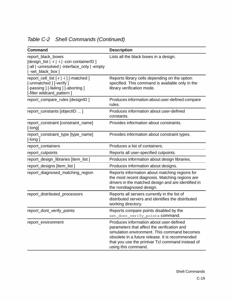
report_black_boxes[design_list | -r | -i | -con containerID ][-all | -unresolved | -interface_only | -empty| -set_black_box ]
Lists all the black boxes in a design.
report_cell_list [-r | -i ] [-matched ][-unmatched ] [-verify ][-passing ] [-failing ] [-aborting ][-filter wildcard_pattern ]
Reports library cells depending on the optionspecified. This command is available only in thelibrary verification mode.
report_compare_rules [designID ] Produces information about user-defined comparerules.
report_constants [objectID ... ] Produces information about user-definedconstants.
report_constraint [constraint_name][-long]
Provides information about constraints.
report_constraint_type [type_name][-long ]
Provides information about constraint types.
report_containers Produces a list of containers.
report_cutpoints Reports all user-specified cutpoints.
report_design_libraries [item_list ] Produces information about design libraries.
report_designs [item_list ] Produces information about designs.
report_diagnosed_matching_region Reports information about matching regions forthe most recent diagnosis. Matching regions aredrivers in the matched design and are identified inthe nondiagnosed design.
report_distributed_processors Reports all servers currently in the list ofdistributed servers and identifies the distributedworking directory.
report_dont_verify_points Reports compare points disabled by theset_dont_verify_points command.
report_environment Produces information about user-definedparameters that affect the verification andsimulation environment. This command becomesobsolete in a future release. It is recommendedthat you use the printvar Tcl command instead ofusing this command.
Table C-2 Shell Commands (Continued)
Command Description
C-19
Shell Commands
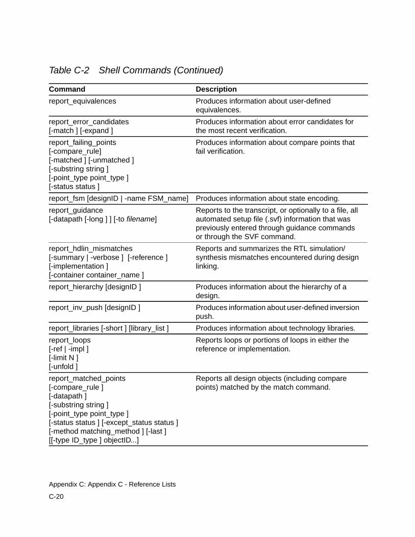
report_equivalences Produces information about user-definedequivalences.
report_error_candidates[-match ] [-expand ]
Produces information about error candidates forthe most recent verification.
report_failing_points[-compare_rule][-matched ] [-unmatched ][-substring string ][-point_type point_type ][-status status ]
Produces information about compare points thatfail verification.
report_fsm [designID | -name FSM_name] Produces information about state encoding.
report_guidance[-datapath [-long ] ] [-to filename]
Reports to the transcript, or optionally to a file, allautomated setup file (.svf) information that waspreviously entered through guidance commandsor through the SVF command.
report_hdlin_mismatches[-summary | -verbose ] [-reference ][-implementation ][-container container_name ]
Reports and summarizes the RTL simulation/synthesis mismatches encountered during designlinking.
report_hierarchy [designID ] Produces information about the hierarchy of adesign.
report_inv_push [designID ] Produces information about user-defined inversionpush.
report_libraries [-short ] [library_list ] Produces information about technology libraries.
report_loops[-ref | -impl ][-limit N ][-unfold ]
Reports loops or portions of loops in either thereference or implementation.
report_matched_points[-compare_rule ][-datapath ][-substring string ][-point_type point_type ][-status status ] [-except_status status ][-method matching_method ] [-last ][[-type ID_type ] objectID...]
Reports all design objects (including comparepoints) matched by the match command.
Table C-2 Shell Commands (Continued)
Command Description
C-20
Appendix C: Appendix C - Reference Lists
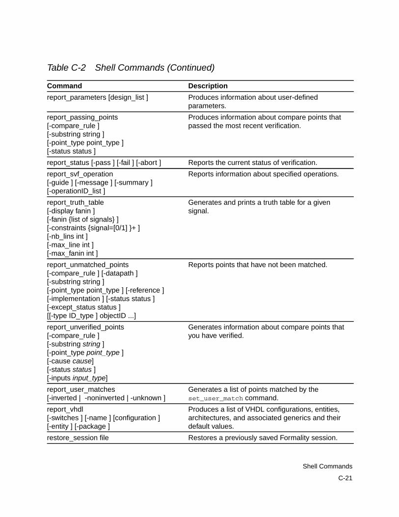
report_parameters [design_list ] Produces information about user-definedparameters.
report_passing_points[-compare_rule ][-substring string ][-point_type point_type ][-status status ]
Produces information about compare points thatpassed the most recent verification.
report_status [-pass ] [-fail ] [-abort ] Reports the current status of verification.
report_svf_operation[-guide ] [-message ] [-summary ][-operationID_list ]
Reports information about specified operations.
report_truth_table[-display fanin ][-fanin {list of signals} ][-constraints {signal=[0/1] }+ ][-nb_lins int ][-max_line int ][-max_fanin int ]
Generates and prints a truth table for a givensignal.
report_unmatched_points[-compare_rule ] [-datapath ][-substring string ][-point_type point_type ] [-reference ][-implementation ] [-status status ][-except_status status ][[-type ID_type ] objectID ...]
Reports points that have not been matched.
report_unverified_points[-compare_rule ][-substring string ][-point_type point_type ][-cause cause][-status status ][-inputs input_type]
Generates information about compare points thatyou have verified.
report_user_matches[-inverted | -noninverted | -unknown ]
Generates a list of points matched by theset_user_match command.
report_vhdl[-switches ] [-name ] [configuration ][-entity ] [-package ]
Produces a list of VHDL configurations, entities,architectures, and associated generics and theirdefault values.
restore_session file Restores a previously saved Formality session.
Table C-2 Shell Commands (Continued)
Command Description
C-21
Shell Commands
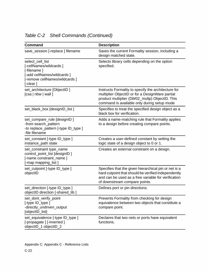
save_session [-replace ] filename Saves the current Formality session, including adesign matched state.
select_cell_list[-cellNames/wildcards ][-filename ][-add cellNames/wildcards ][-remove cellNames/wildcards ][-clear ]
Selects library cells depending on the optionspecified.
set_architecture [ObjectID ][csa | nbw | wall ]
Instructs Formality to specify the architecture formultiplier ObjectID or for a DesignWare partialproduct multiplier (DW02_multp) ObjectID. Thiscommand is available only during setup mode
set_black_box [designID_list ] Specifies to treat the specified design object as ablack box for verification.
set_compare_rule [designID ]-from search_pattern-to replace_pattern [-type ID_type ]-file filename
Adds a name-matching rule that Formality appliesto a design before creating compare points.
set_constant [-type ID_type ]instance_path state
Creates a user-defined constant by setting thelogic state of a design object to 0 or 1.
set_constraint type_namecontrol_point_list [designID ][-name constraint_name ][-map mapping_list ]
Creates an external constraint on a design.
set_cutpoint [-type ID_type ]objectID
Specifies that the given hierarchical pin or net is ahard cutpoint that should be verified independentlyand can be used as a free variable for verificationof downstream compare points.
set_direction [-type ID_type ]objectID direction [-shared_lib ]
Defines port or pin directions.
set_dont_verify_point[-type ID_type ]-directly_undriven_output[objectID_list]
Prevents Formality from checking for designequivalence between two objects that constitute acompare point.
set_equivalence [-type ID_type ][-propagate ] [-inverted ]objectID_1 objectID_2
Declares that two nets or ports have equivalentfunctions.
Table C-2 Shell Commands (Continued)
Command Description
C-22
Appendix C: Appendix C - Reference Lists
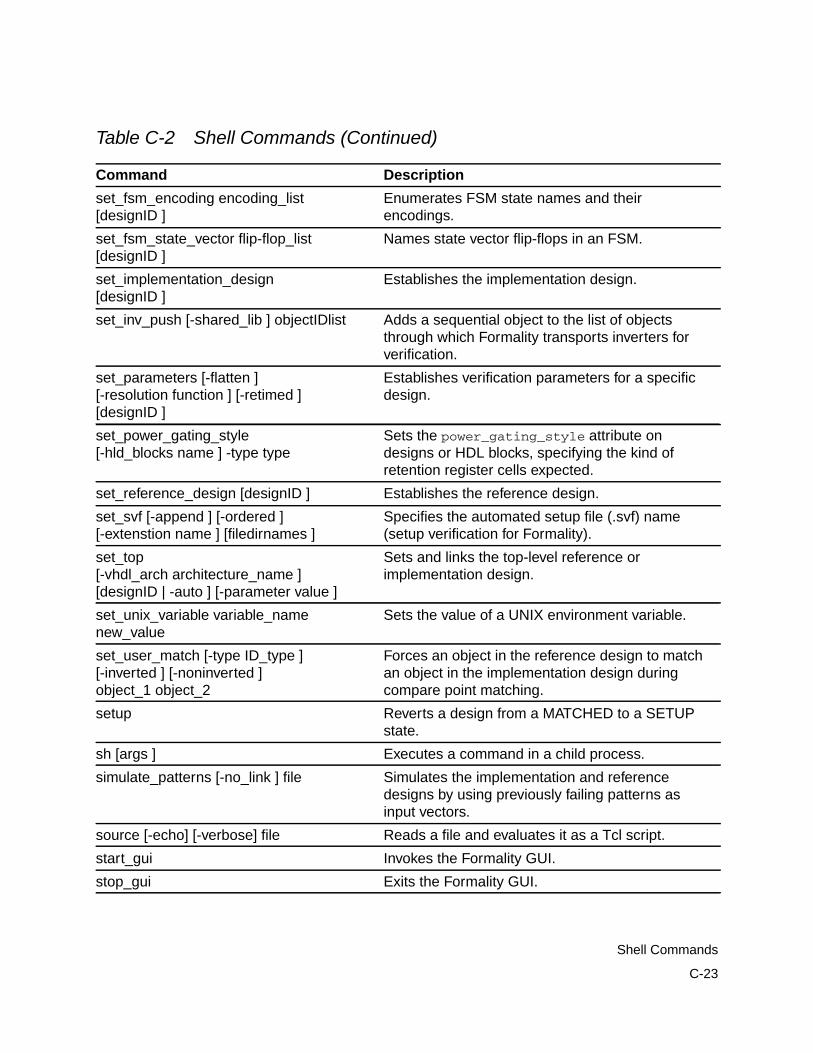
set_fsm_encoding encoding_list[designID ]
Enumerates FSM state names and theirencodings.
set_fsm_state_vector flip-flop_list[designID ]
Names state vector flip-flops in an FSM.
set_implementation_design[designID ]
Establishes the implementation design.
set_inv_push [-shared_lib ] objectIDlist Adds a sequential object to the list of objectsthrough which Formality transports inverters forverification.
set_parameters [-flatten ][-resolution function ] [-retimed ][designID ]
Establishes verification parameters for a specificdesign.
set_power_gating_style[-hld_blocks name ] -type type
Sets the power_gating_style attribute ondesigns or HDL blocks, specifying the kind ofretention register cells expected.
set_reference_design [designID ] Establishes the reference design.
set_svf [-append ] [-ordered ][-extenstion name ] [filedirnames ]
Specifies the automated setup file (.svf) name(setup verification for Formality).
set_top[-vhdl_arch architecture_name ][designID | -auto ] [-parameter value ]
Sets and links the top-level reference orimplementation design.
set_unix_variable variable_namenew_value
Sets the value of a UNIX environment variable.
set_user_match [-type ID_type ][-inverted ] [-noninverted ]object_1 object_2
Forces an object in the reference design to matchan object in the implementation design duringcompare point matching.
setup Reverts a design from a MATCHED to a SETUPstate.
sh [args ] Executes a command in a child process.
simulate_patterns [-no_link ] file Simulates the implementation and referencedesigns by using previously failing patterns asinput vectors.
source [-echo] [-verbose] file Reads a file and evaluates it as a Tcl script.
start_gui Invokes the Formality GUI.
stop_gui Exits the Formality GUI.
Table C-2 Shell Commands (Continued)
Command Description
C-23
Shell Commands
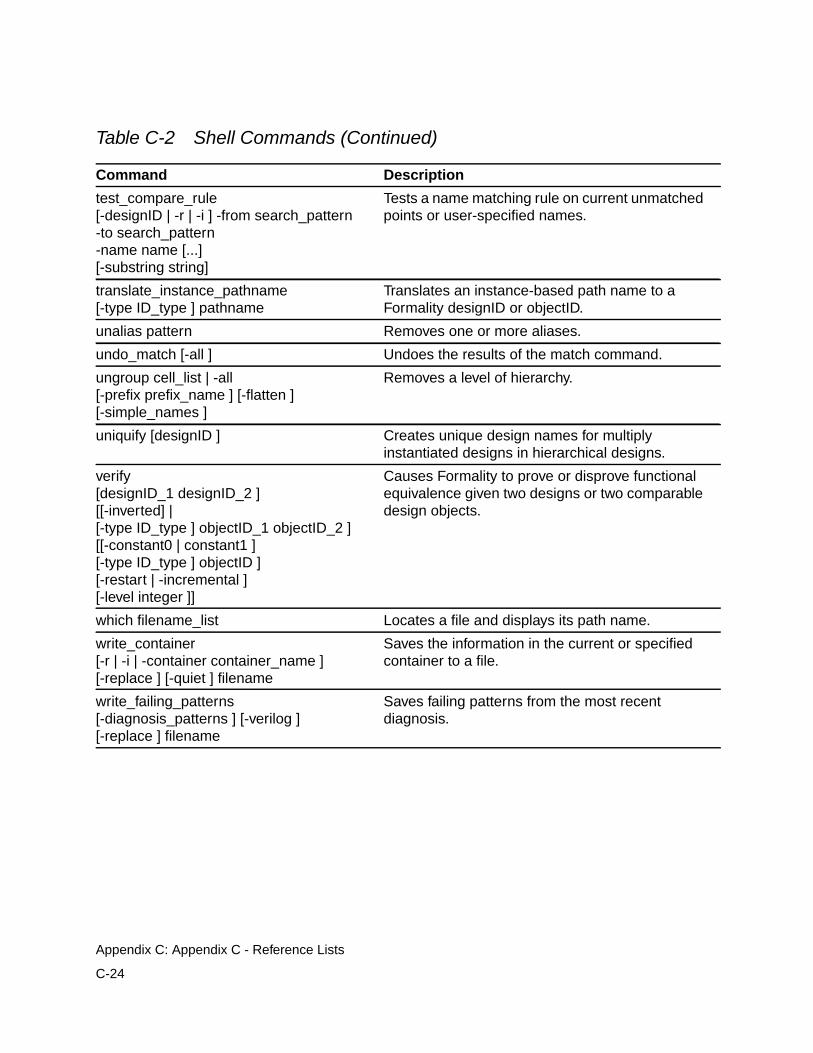
test_compare_rule[-designID | -r | -i ] -from search_pattern-to search_pattern-name name [...][-substring string]
Tests a name matching rule on current unmatchedpoints or user-specified names.
translate_instance_pathname[-type ID_type ] pathname
Translates an instance-based path name to aFormality designID or objectID.
unalias pattern Removes one or more aliases.
undo_match [-all ] Undoes the results of the match command.
ungroup cell_list | -all[-prefix prefix_name ] [-flatten ][-simple_names ]
Removes a level of hierarchy.
uniquify [designID ] Creates unique design names for multiplyinstantiated designs in hierarchical designs.
verify[designID_1 designID_2 ][[-inverted] |[-type ID_type ] objectID_1 objectID_2 ][[-constant0 | constant1 ][-type ID_type ] objectID ][-restart | -incremental ][-level integer ]]
Causes Formality to prove or disprove functionalequivalence given two designs or two comparabledesign objects.
which filename_list Locates a file and displays its path name.
write_container[-r | -i | -container container_name ][-replace ] [-quiet ] filename
Saves the information in the current or specifiedcontainer to a file.
write_failing_patterns[-diagnosis_patterns ] [-verilog ][-replace ] filename
Saves failing patterns from the most recentdiagnosis.
Table C-2 Shell Commands (Continued)
Command Description
C-24
Appendix C: Appendix C - Reference Lists
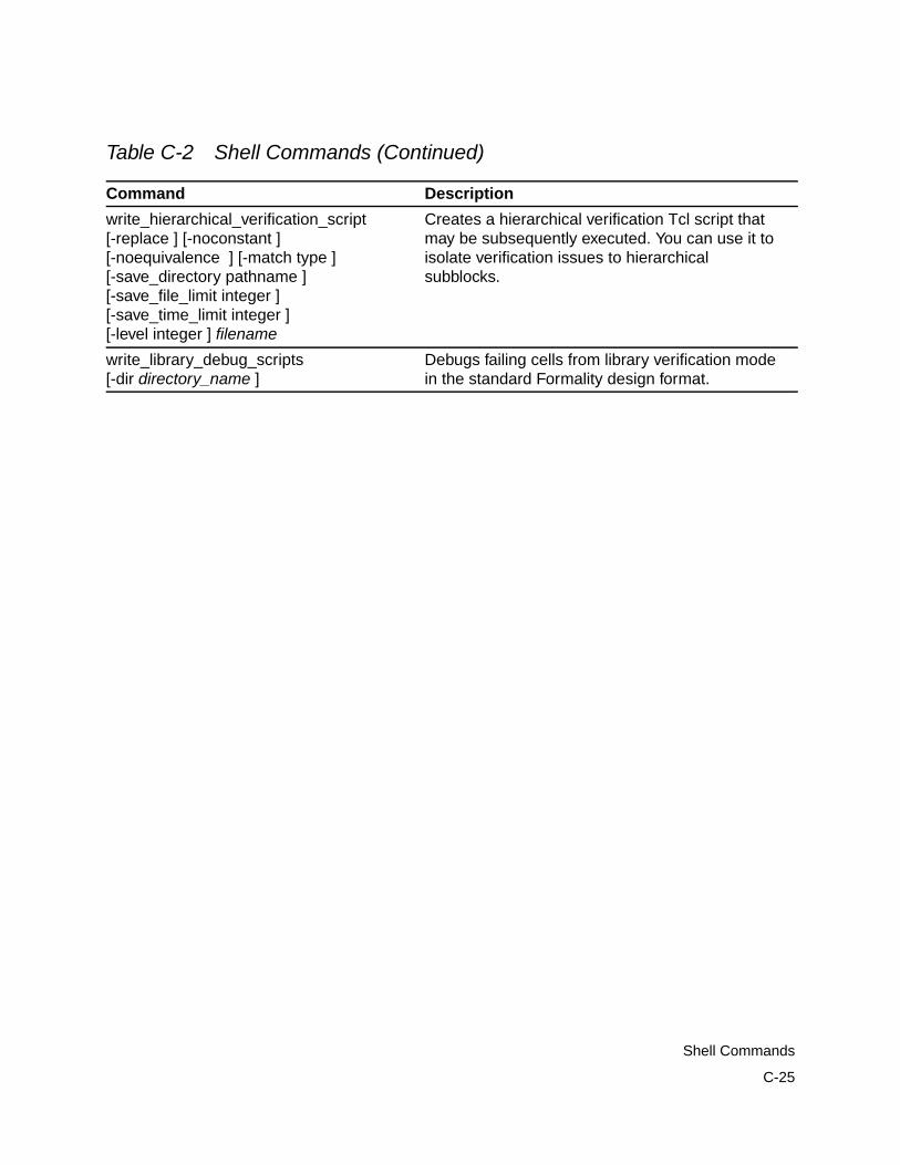
write_hierarchical_verification_script[-replace ] [-noconstant ][-noequivalence ] [-match type ][-save_directory pathname ][-save_file_limit integer ][-save_time_limit integer ][-level integer ] filename
Creates a hierarchical verification Tcl script thatmay be subsequently executed. You can use it toisolate verification issues to hierarchicalsubblocks.
write_library_debug_scripts[-dir directory_name ]
Debugs failing cells from library verification modein the standard Formality design format.
Table C-2 Shell Commands (Continued)
Command Description
C-25
Shell Commands

C-26
Appendix C: Appendix C - Reference Lists
Index
Symbols$isolate() function 5-64$power() function 5-64$retain() function 5-64<< operator> 6-32> operator 3-13>> operator 3-13
Aaborted compare points
defined 6-35during verification 6-36
add_distributed_processors command 6-25,C-10
alias command 3-15, C-10aliases 3-14AND resolution function 5-7application commands A-3architecture_selection_precedence variable
C-2arguments
designID 4-21positional A-4programming default values A-17varying the number of A-17
arithmetic generator
creating multiplier architectures 5-67ASIC libraries 1-16ASIC verification flow diagram 1-7asynchronous bypass logic 5-43asynchronous state-holding loops 5-10attributes, black box 5-19automated setup file 1-17
creating 5-72reading 5-73reading multiple 5-74
automaticcreating compare points 1-26creating containers 1-30
Bbatch mode
controlling verification 6-33interrupting 6-33overview 6-31preparing for 6-31running 6-32scripts 6-31
batch script 1-18, 3-3black box
attributes 5-19controlling 5-16creating cutpoints 5-13
IN-1
debugging 7-14identity check 3-25, 5-17, 5-20loading design interfaces 5-17locating 7-8marking designs 5-18overview 5-15redefining 5-21reporting 5-19resolution function 5-7, 5-8setting pins and port directions 5-21unresolved 5-21verifying 5-15, 7-8
boundary scan 5-39built-in commands A-6bus holders 5-16bus naming
changing the style 4-10mapping 1-29VHDL and Verilog design styles 4-9
bus_dimension_separator_style variable 4-11,C-2
bus_extraction_style variable C-2bus_naming_style variable 4-10, C-2bus_range_separator_style variable C-2
Ccell
defined 1-29library verification 8-1listing 3-16
change_names command 7-28clock gating 5-45clock tree buffering 5-41codes for messages 3-24collapse_all_cg_cells value 5-48color-coding
error candidates 7-33schematic area 7-33
combinational design changes 5-38boundary scan 5-39
clock tree buffering 5-41internal scan insertion 5-38
command alias 3-14command log file 3-27command names, syntax A-4command results, returning A-5command shortcuts 3-12command-line editing 3-9command-line interface (see fm_shell)commands
add_distributed_processors 6-25, C-10alias 3-15, C-10application, using A-3built-in A-6case-sensitivity 3-7change_names 7-28commenting A-5cputime 3-22, C-10create_constraint_type 5-33, C-10create_container 3-25, 4-30, 5-6, 5-20, 5-21,
C-10create_cutpoint_blackbox 7-48, C-10current_container C-10current_design C-11debug_library_cell 8-14, C-11diagnose C-11echo 3-14, 3-29, C-11elaborate_library_cells 8-9, C-11entering commands 3-7error_info C-11exit C-10, C-11find_cells 3-16, C-10, C-11find_designs C-11find_nets 3-16, C-11find_pins 3-16, C-11find_ports 3-16, C-11find_references 3-16, C-11flow control, Tcl A-13fm_shell 1-23, 3-3get_unix_variable C-12getting syntax information 3-21, 3-22
IN-2
group C-12guide C-10, C-12guide_architecture_db C-12guide_architecture_netlist C-10, C-12guide_change_names C-10, C-12guide_datapath C-10, C-12guide_fsm_reencoding C-12guide_group C-13guide_multiplier C-13guide_reg_constant C-13guide_reg_duplication C-13guide_reg_merging C-13, C-14guide_transformation C-14guide_ungroup C-15guide_uniquify C-15guide_ununiquify C-15help 3-21, A-7, C-15-help option 3-21, 3-22history 3-10, C-15interrupting 3-22library_verification 8-4, C-15line breaks 3-7list_key_bindings 3-10, C-15list_libraries C-15man 3-21, 3-22, C-15match 6-5, C-15memory C-15multiline shell commands 3-7nesting A-5positional arguments A-4printenv C-15printvar C-15proc_args C-15proc_body C-15procedures A-7puts 3-14quit C-15read_container 5-88, C-16read_db 4-15, 8-5, 8-6, B-3, C-16read_ddc 4-24, C-16read_fsm_states 5-55, C-16read_milkyway 4-23
read_simulation_library 4-19, B-3, C-16read_verilog 4-17, 8-5, 8-6, C-16, C-17read_vhdl 4-17, C-17recalling 3-12redirect 3-13, C-17remove_black_box C-17remove_compare_rules 6-6, 7-24, C-17remove_constant 5-24, C-17remove_constraint 5-34, C-17remove_constraint_type 5-34, C-17remove_container 5-84, C-17remove_cutpoint 5-14remove_cutpoint_blackbox C-17remove_design 5-82, C-17remove_design_library 5-83, C-17remove_distributed_processors 6-27, C-18remove_dont_verify_point 6-23, C-18remove_equivalence 5-26, 5-27, C-18remove_guidance C-18remove_inv_push C-18remove_library 5-83, 5-84, C-18remove_parameters C-18remove_resistive_drivers C-18remove_user_match 6-6, 7-18, C-18rename_object 7-27, 7-28, C-18report_aborted_points 6-34, C-18report_architecture 5-71, C-18report_black_boxes 5-19, C-19report_cell_list 8-7, C-19report_compare_rules 7-24, C-19report_constants 5-24, C-19report_constraint 5-35, C-19report_constraint_type 5-35, C-19report_containers C-19report_cutpoints 5-14, C-19report_design_libraries C-19report_designs C-19report_diagnosed_matching_region C-19report_distributed_processors 6-26, C-19report_dont_verify_points 6-23, C-19report_environment C-19report_equivalences C-20
IN-3
report_error_candidates C-20report_failing_points 6-34, C-20report_fsm 5-57, C-20report_guidance C-20report_hdlin_mismatches C-20report_hierarchy C-20report_inv_push C-20report_libraries C-20report_loops 5-11, C-20report_matched_points 6-7report_parameters C-21report_passing_points C-21report_power_gating 5-67report_status 8-12, C-21report_truth_table 8-14, C-21report_unmatched_inputs 7-8report_unmatched_points 6-6, C-20, C-21report_unverified_points C-21report_user_matches 7-18, C-21restore_session 5-89, C-21returning results 3-7save_session 5-87, C-22select_cell_list 8-8, C-22set 3-28set_architecture 5-69, C-22set_black_box 5-18, C-22set_compare_rule 7-20, C-22set_constant 5-23, C-22set_constraint 5-32, C-22set_cutpoint 5-13, C-22set_direction C-22set_dont_verify_point 6-23, C-22set_equivalence 5-25, 5-26, C-22set_fsm_encoding 5-56, C-23set_fsm_state_vector 5-56, C-23set_implementation_design C-23set_inv_push 5-51, 5-52, C-23set_parameters 5-62, C-23set_power_gating_style 5-67, C-23set_reference_design C-23set_svf 5-72, C-23set_top 4-24, C-23
set_unix_variable C-23set_user_match 5-13, 5-41, 7-16, C-23setup 6-5, C-23sh C-23simulate_patterns C-23source 3-26, C-23special characters A-5start_gui C-23stop_gui C-23Tcl syntax A-1test_compare_rule 1-29, 7-23translate_instance_pathname C-24unalias 3-15, C-24undo_match 6-7, C-24ungroup C-24uniquify C-24verify 6-19, 6-21, 6-34, 8-9, C-24which C-24write_container 5-86, C-24write_failing_patterns 7-47, C-24write_hierarchical_verification_script 6-30,
C-25write_library_debug_scripts 8-15, C-25
commenting commands A-5compare points
aborted 6-35, 6-36automatic creation of 1-26debugging 7-15debugging unmatched 6-9defining your own 1-27exact-name matching 6-12example 1-27failing 6-35listing user-matched points 7-18mapping names between 1-25, 1-27matched state 6-3matching 6-5
flow 6-3related variables 6-12techniques 1-27, 6-10
name filtering 6-14name-based matching 6-10
IN-4
net-name matching 6-18non-name-based matching 6-11objects used to create 1-25overview 1-25passing 6-35removing 7-18removing from verification set 6-22restart matching 6-7revert to NOT_RUN state 6-7signature analysis 6-16status messages 6-35topological equivalence 6-15undoing match command 6-7unmatched, debugging techniques 6-8unmatched, reporting 6-6unverified 6-35verifying single 6-19, 6-21
compare rules 7-19checking syntax 1-29defining 7-20listing 7-24mapping object names 1-28overview 1-28removing 7-24testing 7-23
complete verification 1-26concepts
black boxes 5-15compare points 1-25compare rules 1-28constants 5-22containers 1-29current container 4-31cutpoints 5-12design equivalence 1-31design libraries 1-19design objects 1-29designs 4-8don’t care information 5-3external constraints 5-30FSMs 5-53implementation design 1-34
libraries 1-19logic cones 1-33LSSD cell 5-62reference design 1-34resolution functions 5-7signature analysis 6-16verification 6-19
consensus, resolution function 5-7consistency, defined 1-12console window
Formality prompt 3-18, 3-19toolbar 7-31transcript area 3-19
constantsdefining 5-22listing 5-24overview 5-22propagating 5-22, 5-37removing 5-24types 5-22user-defined 5-22
constraint module 5-33containers
automatic creation 1-30contents 1-29creating 1-30, 4-30current 1-31, 4-31listing 4-31managing 4-29naming 4-30overview 1-29reading data into 1-31removing 5-84restoring 5-88saving 1-18, 1-21, 5-86setting up 4-29
control flow commands, Tcl A-13control statements 6-33Control-c interrupt 3-22, 6-29, 6-33controlling
black boxes 5-16
IN-5
verification runtimes 6-24copying text
from shell window 3-18, 3-19from transcript area 3-19
coverage percentage 7-33cputime command 3-22, C-10create_constraint_type command 5-33, C-10create_container command 3-25, 4-30, 5-6,
5-20, 5-21, C-10create_cutpoint_blackbox command 7-48,
C-10creating
automated setup files 5-72constraint types 5-33containers 1-30, 4-30cutpoints 5-13don’t care cells 5-3multiplier architectures 5-67procedures A-16tutorial directories 2-2
.cshrc 2-2current
container 1-31, 4-31design 4-31
current_container command C-10current_design command C-11cutpoint black boxes 5-13
removing 5-14reporting 5-14
Ddata
ASIC libraries 1-16automated setup files 1-17containers 1-18, 1-21, 1-29failing patterns 1-21, 7-47, 7-48.fpt files 1-21, 7-47.fsc files 1-18, 1-21, 5-86.fss files 1-18, 1-21, 5-87input file types 1-15
output file types 1-20reading
Synopsys database files (.db) 4-9Verilog files 4-9VHDL files 4-9
removing 5-82restoring 5-88, 5-89saving 1-18, 1-21, 5-85Synopsys database files (.db) 1-16, 4-9Verilog files 1-16, 1-17, 4-9Verilog simulation library files 1-17VHDL files 1-17, 4-9
.db files 1-16
.ddc databasesdesigns from 4-22reading designs 4-24
.ddc files 1-16, 4-8, 4-22debug_library_cell command 8-14, C-11debugging
black boxes 7-14compare points 7-15determining failure causes 7-7eliminating setup possibilities 7-14failing patterns 7-46gathering information 7-4library cells 8-14matching with compare rules 7-19renaming objects 7-27setting compare points to match 7-15strategies 7-4subset matching 7-24unmatched compare points 6-9using diagnosis 7-9using logic cones 7-11working with subcones 7-43
definingcompare points 1-27constants 5-22FSM states 5-54
deletingcontainers 5-84
IN-6
design libraries 5-83designs 5-82technology libraries 5-83
dereferencing variables A-5design equivalence 5-25
overview 1-31design flow, methodology 1-3, 1-4design libraries 1-19
default name 4-22library ID 1-20reading 1-20removing 5-83restoring 1-18, 5-88, 5-89saving 5-86viewing 1-20
design management 1-12design objects
finding 7-34generating lists 7-35overview 1-29renaming 7-26unmatched 1-27used in compare point creation 1-25
designID, argument 4-21designs
black box 5-85bus naming, VHDL and Verilog 4-9constants 5-22current 4-31designID 4-21failing patterns, simulating 7-48flattened 5-36hierarchy separator style 5-36implementation 1-34, 1-35inserting cutpoints 5-13linking (with set_top) 4-14locating problem areas 7-4marking as black boxes 5-18overview 4-8propagating constants 5-22reference 1-34, 1-35
removing 5-82restoring 5-88retiming 5-59retiming using Design Compiler 5-59retiming with other tools 5-62saving 5-86, 5-87setting the top-level design 4-27setting up 5-1Synopsys database (.db) 1-16, 4-8Verilog 1-16, 1-17, 4-9VHDL 1-17, 4-9
DesignWarereading in instantiated 4-12root directory 2-8supported components 4-11
diagnose command C-11diagnosis
debugging with 7-9interrupting 3-22overview 1-13
diagnosis_enable_error_isolation variable C-2diagnosis_enable_find_matching_candidates
variable C-2diagnosis_pattern_limit variable C-2dimension separator styles 4-9directives in VHDL and Verilog ignored/used
4-12directory
creating for tutorial 2-2work 1-22
distributed verification process 6-25setting up environment 6-25verifying environment 6-27
distributed_64bit_mode variable C-2distributed_verification_mode variable C-2distributed_work_directory variable C-3don’t care cells
creating 5-3don’t care information
overview 5-3verification modes 1-31
IN-7
dw_foundation_threshold variable C-3
Eecho command 3-14, 3-29, C-11editing, command line 3-9elaborate_library_cells command 8-9, C-11enable_mulitplier_generation variable C-3enable_multiplier_generation variable 5-69enable_power_gating variable 5-67equality, verifying 1-12equivalences 5-25
defining 5-26listing user-defined 5-27removing 5-26
error candidatescolor-coding 7-33coverage percentage 7-33
error messages 3-23, 3-24error_info command C-11escape quoting A-5exact-name compare point matching 6-12examples
bus holder 5-16compare point, creation 1-27logic cone 1-34multiply-driven nets 5-8resolution function 5-8schematic view window 7-30
exit command C-10, C-11expressions
evaluation, Tcl A-12grouping A-5
external constraintscreating constraint types 5-33overview 5-30removing 5-34removing constraint type 5-34reporting 5-35reporting constraint types 5-35
setting 5-32types 5-31user-defined 5-33
Ffailed verification 6-36failing compare points, defined 6-35failing patterns
applying from logic cone window 7-46applying in the logic cone view window 7-38coverage percentage 7-33default number 7-44file 1-21limiting 7-44saving 7-47simulating 7-48
features, Formality 1-3files
ASIC libraries 1-16automated setup 1-17batch script 1-18, 6-31black boxing 5-85command log 3-27.ddc 4-8, 4-22failing patterns 1-21, 7-47fm_shell_command log 1-23fm_shell_command.log 1-22formality.log 1-22, 7-4format types supported 1-15.fpt type 1-21, 7-47.fsc type 1-18, 1-21, 5-86.fss type 1-18, 1-21, 5-87input 1-15log 1-23name mapping 1-18output 1-20reading automated setup 5-73removing 5-82search path 3-28session log 3-27
IN-8
state files for FSMs 1-17, 5-55Synopsys database (.db) 1-16, 4-8.synopsys_fm.setup 1-24Verilog 1-16, 1-17, 4-9Verilog simulation library 1-17VHDL 1-17, 4-9
find_cells command 3-16, C-10, C-11find_designs command C-11find_nets command 3-16, C-11find_pins command 3-16, C-11find_ports command 3-16, C-11find_references command 3-16, C-11find_svf_operation command 5-78, C-11finding
design objects 7-34lists of design objects 7-35unmatched black boxes 7-8
finite state machines (FSMs)defining states individually 5-54, 5-56listing state encoding information 5-57overview 5-53preparing for verification 5-54state files 1-17, 5-55
flattening designsconstant propagation 5-37during verification 5-36separator style 5-36
fm_shell 1-12getting help 3-20listing commands 3-21starting 3-3
fm_shell command 1-23, 3-3-f option 3-3, 3-4, 6-32-gui option 3-4-no_init option 3-4syntax A-3-version option 3-4within GUI 3-18
fm_shell_command.log file 1-22for loops, Tcl flow control A-14
foreach command, Tcl flow control A-15Formality
generated file names, controlling 1-23introduction 1-2library support B-1log files 1-22, 7-4supported library formats B-3
formality_svf directory 5-75formality.log file 1-22, 7-4format, of files 1-15.fpt files 1-21, 7-47.fsc files 1-18, 1-21, 5-86FSM reencoding 5-54.fss files 1-18, 1-21, 5-87
Ggate-level netlists B-4gate-to-gate verification 1-10get_unix_variable command C-12golden design 1-2, 1-34graphical user interface, see GUI 1-11group command C-12grouping expressions A-5grouping words, Tcl commands A-6GUI
current container 4-31displaying during startup 3-4logic cone view window 7-38overview 1-11, 3-17starting 3-5
gui_report_lentgh_limit variable C-3guide command C-10, C-12guide_architecture_db command C-12guide_architecture_netlist command C-10,
C-12guide_change_names command C-10, C-12guide_datapath command C-10, C-12guide_fsm_reencoding command C-12guide_group command C-13
IN-9
guide_inv_push variable C-13guide_multiplier command C-13guide_reg_constant command C-13guide_reg_duplication command C-13guide_reg_encoding variable C-10, C-13guide_reg_merging command C-13, C-14guide_retiming variable C-14guide_retiming_decompose variable C-14guide_retiming_finished variable C-14guide_retiming_multibit variable C-14guide_transformation command C-14guide_ungroup command C-15guide_uniquify command C-15guide_ununiquify command C-15
Hhdlin_auto_netlist variable 4-22, C-3hdlin_auto_top variable 4-27, C-3hdlin_disable_tetramax_define variable C-3hdlin_do_inout_port_fixup variable C-3hdlin_dwroot variable 4-12, C-3hdlin_dyn_array_bnd_check variable C-3hdlin_enable_verilog_assert variable C-3hdlin_error_on_mismatch_message variable
C-2, C-3hdlin_ignore_builtin variable C-2, C-3hdlin_ignore_dc_script variable C-4hdlin_ignore_full_case variable 4-13, C-4hdlin_ignore_label variable C-4hdlin_ignore_label_applies_to variable C-4hdlin_ignore_map_to_entity variable C-4hdlin_ignore_map_to_module variable C-4hdlin_ignore_map_to_operator variable C-2,
C-4hdlin_ignore_parallel_case variable 4-13, C-4hdlin_ignore_resolution_method variable C-4hdlin_ignore_synthesis variable 4-14, C-4hdlin_ignore_translate variable 4-14, C-4
hdlin_infer_multibit variable 5-5hdlin_infer_mux variable C-4hdlin_interface_only variable C-4hdlin_interface_only variables 5-17hdlin_library_directory variable 4-17, C-4hdlin_library_enhanced_analysis variable C-4hdlin_library_file variable 4-17, C-4hdlin_library_report_summary variable C-5hdlin_multiplier_architecture variable 5-68, C-5hdlin_normalize_blackbox_busses variable
C-2, C-5hdlin_synroot variable C-5hdlin_unresolved_modules variable C-5hdlin_verilog_95 variable C-5hdlin_verilog_wired_net_interpretation
variable C-5hdlin_vhdl_87 variable C-5hdlin_vhdl_auto_file_order variable C-5hdlin_vhdl_forgen_inst_naming variable C-5hdlin_vhdl_fsm_encoding variable C-5hdlin_vhdl_integer_range_constraint variable
C-5hdlin_vhdl_others_covers_extra_states
variable C-5hdlin_vhdl_presto_naming variable C-5hdlin_vhdl_presto_shift_div variable C-6hdlin_vhdl_strict_libs variable 4-21, C-6hdlin_vhdl_use_87_concat variable C-6hdlin_warn_on_mismatch_message variable
C-6help
command 3-21, A-7, C-15fm_shell commands 3-20
-help, options 3-21hierarchical designs 5-35
GUI representation 4-21hierarchy separator style 5-36propagating constants 5-37storaging 1-30traversing 7-30, 7-33
IN-10
hierarchical separator character, defining 5-36hierarchical verification 6-29history command 3-10, C-15
Iidentity check, black boxes 3-25, 5-17, 5-20if command, Tcl flow control A-13impl variable C-6implementation design 1-2
establishing 1-35overview 1-34restoring 5-89
implementation libraries 8-6inconclusive verification status 6-36input
file types 1-15redirecting during batch jobs 6-32
insertingcutpoints 5-13
install directory 2-2installation 2-2interface
command line 1-12interfaces
GUI 1-11, 3-17internal scan insertion 5-38interpreting verification results 6-33interrupting
batch mode verification 6-33diagnosis 3-22fm_shell commands 3-22verification 6-29
introduction to Formality 1-1inversion push 5-50
environmental 5-52instance-based 5-51
invokingfm_shell 2-3, 3-1, 3-3GUI 3-5
isolatingdesign problems 7-1subcones 7-44
Llibraries
design 1-19DesignWare 4-11functional verification B-13loading order B-15support B-1supported formats B-3Synopsys synthesis B-3synthesis, updating B-4synthesis, using B-9technology 1-19, 1-20verification process B-12Verilog simulation 4-19, B-3Verilog, using B-9
library filesVerilog simulation 1-17
library ID 1-20library verification 8-1
debugging process 8-9, 8-14implementation library 8-6initializing 8-4process flow 8-3reference library 8-5reporting library cells 8-7reporting status 8-12sample Tcl script 8-10specifying the cells to verify 8-8status messages 8-13supported formats 8-3truth tables 8-14verifying the libraries 8-9versus design verification 8-3, 8-6, 8-10
library_verification command 8-4, C-15limiting
failing patterns 7-44messages 3-25
IN-11
linking designs 4-14list_key_bindings command 3-10, C-15list_libraries command C-15listing
constants 5-24design objects 7-35fm_shell commands 3-21previously entered commands 3-10
lists in Tcl A-8loading design interfaces, black boxes 5-17locating
design objects 7-34design problems 7-4lists of design objects 7-35problems 5-22unmatched black boxes 7-8
log file 3-27log files 1-22, 1-23
fm_shell_command.log 1-22formality.log 1-22, 7-4
logic cone view windowapplying failed patterns 7-38overview 7-38removing non-controlling logic 7-43subcones 7-43
logic cone, diagnose 7-11logic cones 7-45
originating point 1-33overview 1-33termination points 1-33viewing 7-38
loops, Tcl A-14LSSD cell, defined 5-62
Mman command 3-21, 3-22, C-15man page overview 3-21managing, black boxes 5-16mapping names
buses 1-29, 4-10compare points 1-25, 1-27compare rules 1-28design objects 7-26file used for 1-18
marking designs as black boxes 5-18match command 6-5, C-15matched verification status 6-3matching compare points 6-5memory command C-15message thresholds, setting 3-25message_level_mode variable C-6messages
codes 3-24error 3-23limiting 3-25setting threshold 3-25severity 3-23syntax 3-23types 3-25
methodology, design flow 1-3, 1-4Milkyway databases
allowed formats 4-8reading 4-22
Milkyway databases, reading 4-23multibit support 5-5mw_logic0_net variable 4-23, C-6mw_logic1_net variable 4-23, C-6
Nname filtering compare point matching 6-14name mapping see mapping namesname_match variable 6-12, 6-13, C-6name_match_allow_subset_match variable
6-12, 7-25, C-6name_match_based_on_nets variable 6-12,
6-18, C-6name_match_filter_chars variable 6-12, 6-14,
7-24, C-6
IN-12
name_match_flattend_hierarchy_separator_style variable C-6
name_match_flattened_hierarchy_separator_style variable 6-12
name_match_multibit_register_reverse_ordervariable 6-12, 6-13, C-6
name_match_net variable C-6name_match_pin_net variable C-6name_match_use_filter variable 6-12, 6-14,
7-25, C-7name_matched_flattened_hierarchy_separato
r_style variables 5-36nesting commands A-5, A-11net-name compare point matching 6-18nets
constant value 5-22listing 3-16setting to a constant 5-23with multiple drivers 5-6
Ooptions, syntax A-4OR resolution function 5-7output
file types 1-20redirecting 3-13
overviewblack boxes 5-15compare points 1-25compare rules 1-28constants 5-22containers 1-29design equivalence 1-31design libraries 1-19design objects 1-29designs 4-8don’t care information 5-3external constraints 5-30finite state machines (FSMs) 5-53Formality 1-2
implementation design 1-34libraries 1-19library support B-2library verification 8-3logic cones 1-33man pages 3-21reference design 1-34reports 1-21resolution functions 5-7technology libraries 1-19verification 6-19
overwriting file names 1-23
Pparameters
automatically flattening designs 5-36bus naming 1-29, 4-10constant propagation 5-37design 5-1hierarchical separator style 5-36identity check, black boxes 3-25, 5-20message threshold 3-25multiply-driven net resolution 5-8restoring 5-89saving 5-86, 5-87
passing compare points 6-35path, setting 2-2pins
defining direction 5-21listing 3-16
portsconstant value 5-22defining direction 5-21direction, black boxes 5-16listing 3-16setting to a constant 5-23
positional arguments with, commands A-4previous session, sourcing 3-27printenv command C-15printing
IN-13
schematics 7-37transcript area 3-18
printvar command C-15problem areas, see troubleshootingproc_args command C-15proc_body command C-15procedures
creating A-16default A-7
process flow, general 1-13propagating constants 5-22, 5-37puts built-in command 3-14
Qquick-start tutorial 2-1quit command C-15quotation marks, using A-6quotes, using A-6
Rread_container command 5-88, C-16read_db command 4-15, 8-5, 8-6, B-3, C-16read_ddc command 4-24, C-16read_fsm_states command 5-55, C-16read_milkyway command 4-23read_simulation_library command 4-19, B-3,
C-16read_verilog command 4-17, 8-5, 8-6, C-16,
C-17read_vhdl command 4-17, C-17reading
containers 5-88.ddc databases 4-22FSM states 5-55mutliple automated setup files 5-74session data 5-89
redefiningblack boxes 5-21
redirect command 3-13, C-17redirecting
input 6-32output 3-13
ref variable C-7reference design 1-2
establishing 1-35overview 1-34
reference libraries 8-5references, design objects 3-16regression testing 1-35remove_black_box command C-17remove_compare_rules command 6-6, 7-24,
C-17remove_constant command 5-24, C-17
-type option 5-24remove_constraint command 5-34, C-17remove_constraint_type command 5-34, C-17remove_container command 5-84, C-17remove_cutpoint command 5-14remove_cutpoint_blackbox command C-17remove_design command 5-82, C-17remove_design_library command 5-83, C-17remove_distributed_processors command
6-27, C-18remove_dont_verify_point command 6-23,
C-18remove_equivalence command 5-26, 5-27,
C-18remove_guidance command C-18remove_inv_push command C-18remove_library command 5-83, 5-84, C-18remove_parameters command C-18remove_resistive_drivers command C-18remove_user_match command 6-6, 7-18, C-18removing
containers 5-84design libraries 5-83designs 5-82subcones 7-43
IN-14
technology libraries 5-83rename_object command 7-27, 7-28, C-18renaming design objects 7-26report_aborted_points command 6-34, C-18report_architecture command 5-71, C-18report_black_boxes command 5-19, C-19report_cell_list command 8-7, C-19report_compare_rules command 7-24, C-19report_constants command 5-24, C-19report_constraint command 5-35, C-19report_constraint_type command 5-35, C-19report_containers command C-19report_cutpoints command 5-14, C-19report_design_libraries command C-19report_designs command C-19report_diagnosed_matching_region command
C-19report_distributed_processors command 6-26,
C-19report_dont_verify_points command 6-23,
C-19report_environment command C-19report_equivalences command C-20report_error_candidates command C-20report_failing_points command 6-34, C-20report_fsm command 5-57, C-20report_guidance command 5-79, C-20report_hdlin_mismatches command C-20report_hierarchy command C-20report_inv_push command C-20report_libraries command C-20report_loops command 5-11, C-20report_parameters command C-21report_passing_points command C-21report_power_gating command 5-67report_status command 8-12, C-21report_svf_operation command 5-79report_truth_table command 8-14, C-21report_unmatched_inputs command 7-8
report_unmatched_points command 6-6, 6-7,C-20, C-21
report_unverified_points command C-21report_user_matches command 7-18, C-21reporting
black boxes 7-8reporting black boxes 5-19reports 7-4
compare rules 7-24constants, user-defined 5-24containers 4-31equivalences, user-defined 5-27finite state machine (FSMs) information 5-57library cells 8-7library verification results 8-12overview 1-13, 1-21truth tables 8-14
requirements, Formality 1-8resolution functions
multiply-driven nets 5-7overview 5-7
resolvingmultiply-driven nets 5-7nets with multiple drivers 5-6
restore_session command 5-89, C-21restoring
data 1-18, 5-88, 5-89parameters 5-89session 1-18, 5-89
results 6-36retimed designs, working with 5-59retiming designs
using Design Compiler 5-59using other tools 5-62verifying with Formality 5-61
returning shell command results A-5rigid quoting A-5root directory 1-24RTL B-4
designs 1-9
IN-15
RTL-to-gates verification 1-9RTL-to-RTL verification 1-9
Ssave_session command 5-87, C-22saving
containers 1-18, 1-21, 5-86data 5-85failing patterns 7-47parameters 5-86, 5-87session 1-21, 5-87
schematic view windowexample 7-30zooming 7-36
schematic_expand_logic_cone variable C-7schematics
printing 7-37viewing logic cones 7-38
script filebatch jobs 6-31sourcing 3-26, 6-32tasks 3-26
search pathexamining 3-29files 3-28
search_path variable 3-28, C-7select_cell_list command 8-8, C-22separating list items, Tcl commands A-9separator character, bus names 4-11, 4-12sequential design changes 5-42
asynchronous bypass logic 5-43clock gating 5-45inversion push 5-50
session data, restoring 5-89set command 3-28set_architecture command 5-69, C-22set_black_box command 5-18, C-22set_compare_rule command 7-20, C-22set_constant command 5-23, C-22
-type option 5-23set_constraint command 5-32, C-22set_cutpoint command 5-13, C-22set_direction command C-22set_dont_verify –directly_undriven_output
command 4-5set_dont_verify_point command 6-23, C-22set_equivalence command 5-25, 5-26, C-22set_fsm_encoding command 5-56, C-23set_fsm_state_vector command 5-56, C-23set_implementation_design command C-23set_inv_push command 5-51, 5-52, C-23set_parameters command 5-62, C-23set_power_gating_style command 5-67, C-23set_reference_design command C-23set_svf command 5-72, C-23set_top command 4-24, C-23
conditions 4-25set_unix_variable command C-23set_user_match command 5-13, 5-41, 7-16,
C-23setting
implementation design 1-35message thresholds 3-25pins and port directions 5-21reference design 1-35top-level design 4-27
setup command 6-5, C-23setup files 1-24Setup-free Flow 4-5severity rating for messages 3-23, 3-25sh command C-23sh_arch variable C-7sh_continue_on_error variable C-7sh_enable_line_editing variable 3-10sh_enable_page_mode variable C-7sh_line_editing_mode variable 3-10sh_product_version variable C-7
IN-16
sh_source_uses_search_path variable 3-28,C-7
shell interface, starting 3-3shell window
copying text 3-18, 3-19signature analysis 6-16signature_analysis_allow_net_match variable
C-2, C-7signature_analysis_allow_subset_match
variable C-7signature_analysis_match_blackbox_input
variable C-7signature_analysis_match_blackbox_output
variable C-7signature_analysis_match_compare_point
variable C-7signature_analysis_match_compare_points
variable C-8signature_analysis_match_datapath variable
C-7signature_analysis_match_hierarchy variable
C-7signature_analysis_match_net variable C-7signature_analysis_match_primary_input
variable 6-12, C-2, C-8signature_analysis_match_primary_output
variable 6-12, 6-17, C-8signature_analysis_matching variable 6-12,
6-17simulate_patterns command C-23simulating previously failing patterns 7-48single-state holding elements 5-62source command C-23
batch jobs 6-32-echo option 3-26file search exception 3-28syntax 3-26-verbose option 3-26
sourcingprevious sessions 3-27script files 3-26, 6-32
special charactersTcl A-5
start_gui command C-23starting
fm_shell 2-3, 3-1, 3-3GUI 3-5
state files for FSMs 1-17, 5-55stop_gui command C-23subcones 7-43, 7-44succeeded verification 6-36supported library formats B-3svf_datapath variable C-8svf_ignore_unqualified_fsm_information
variable 5-54switch command, Tcl flow control A-16Synopsys database files (.db) 1-16, 4-8, 4-9Synopsys synthesis libraries B-3synopsys_auto_setup mode 2-6, 4-3synopsys_auto_setup variable C-2.synopsys_fm.setup file 1-24synopsys_root variable C-8syntax
fm_shell commands A-4procedures A-7
synthesis libraries, updating B-4
TTcl
arguments, varying the number of A-17break command A-15commands that support lists A-8continue command A-15control flow commands A-13expression evaluation A-12for loops A-14foreach command A-15grouping words A-6lists A-8nesting commands A-11
IN-17
overview A-1quoting values A-6separating list items 3-8, A-9special characters A-5switch command A-16user-defined variables A-10while command A-14
Tcl variablesdistributed_64bit_mode 6-27distributed_verification_mode 6-27distributed_work_directory 6-25sh_source_uses_search_path 3-28
TECH_WORK library 4-15technology libraries 1-19
default name 4-15library ID 1-20reading 1-20, 4-7removing 5-83restoring 1-18, 5-88, 5-89saving 5-86, 5-87shared 1-19, 4-30, 4-31unshared 1-19, 4-30verifying 8-1viewing 1-20
terminating loops, Tcl A-15test_compare_rule command 1-29, 7-23thresholds, message level 3-25toolbar, console window 7-31top-level designs 4-14topological equivalence 6-15transcript area
copying text 3-19printing 3-18
transcript window 7-4translate_instance_pathname command C-24traversing hierarchical designs 7-30, 7-33troubleshooting
asynchronous state-holding loops 5-10black boxes 7-8, 7-14determining failure cause 7-4, 7-7eliminating setup possibilities 7-14
extraneous bus drivers 5-16failed verifications 7-1failing patterns 7-46failing patterns, simulating 7-48gathering information 7-4incomplete verification 7-4locating problems 5-22logic cones, viewing 1-33matching with compare rules 7-19problem areas, locating 7-4renaming objects 7-27setting compare points to match 7-15subset matching 7-24unmatched compare points 6-9using diagnosis 7-9using logic cones 7-11working with subcones 7-43
truth table 8-14tutorial 2-1
directory 2-3tutorial directories
creating 2-2
Uunalias command 3-15, C-24undo_match command 6-7, C-24ungroup command C-24uniquify command C-24unmatched compare points 6-6unverified compare points, defined 6-35updating, synthesis libraries B-4usage model diagram 1-5user-defined
compare points 1-27constants 5-22
removing 5-24reporting 5-24
equivalences 5-25variables, Tcl A-10
user-defined equivalence, removing 5-26
IN-18
user-specified file names 1-23/usr/synopsys root directory 1-24
Vvalues, quoting A-6variables
architecture_selection_precedence C-2bus_dimension_separator_style 4-11, C-2bus_extraction_style C-2bus_naming_style 4-10, C-2bus_range_separator_style C-2dereferencing A-5diagnosis_enable_error_isolation C-2diagnosis_enable_find_matching_candidate
s C-2diagnosis_pattern_limit C-2distributed_64bit_mode C-2distributed_verification_mode C-2distributed_work_directory C-3dw_foundation_threshold C-3enable_multiplier_generation 5-69, C-3enable_power_gating 5-67get_unix_variable C-12gui_report_length_limit C-3guide_inv_push C-13guide_reg_encoding C-10, C-13guide_retiming C-14guide_retiming_decompose C-14guide_retiming_finished C-14guide_retiming_multibit C-14hdlin_auto_netlist 4-22, C-3hdlin_auto_top 4-27, C-3hdlin_disable_tetramax_define C-3hdlin_do_inout_port_fixup C-3hdlin_dwroot 4-12, C-3hdlin_dyn_array_bnd_check C-3hdlin_enable_verilog_assert C-3hdlin_error_on_mismatch_message C-2,
C-3hdlin_ignore_builtin C-2, C-3hdlin_ignore_dc_script C-4
hdlin_ignore_full_case 4-13, C-4hdlin_ignore_label C-4hdlin_ignore_label_applies_to C-4hdlin_ignore_map_to_entity C-4hdlin_ignore_map_to_module C-4hdlin_ignore_map_to_operator C-2, C-4hdlin_ignore_parallel_case 4-13, C-4hdlin_ignore_resolution_method C-4hdlin_ignore_synthesis 4-14, C-4hdlin_ignore_translate 4-14, C-4hdlin_infer_multibit 5-5hdlin_infer_mux C-4hdlin_interface_only 5-17, C-4hdlin_library_directory 4-17, C-4hdlin_library_enhanced_analysis C-4hdlin_library_file 4-17, C-4hdlin_library_report_summar C-5hdlin_multiplier architecture 5-68hdlin_multiplier_architecture C-5hdlin_normalize_blackbox_busses C-2, C-5hdlin_synroot C-5hdlin_unresolved_modules C-5hdlin_verilog_95 C-5hdlin_verilog_wired_net_interpretation C-5hdlin_vhdl_87 C-5hdlin_vhdl_auto_file_order C-5hdlin_vhdl_forgen_inst_naming C-5hdlin_vhdl_fsm_encoding C-5hdlin_vhdl_integer_range_constraint C-5hdlin_vhdl_others_covers_extra_states C-5hdlin_vhdl_presto_naming C-5hdlin_vhdl_presto_shift_div C-6hdlin_vhdl_strict_libs 4-21, C-6hdlin_vhdl_use_87_concat C-6hdlin_warn_on_mismatch_message C-6impl C-6message_level_mode C-6mw_logic0_net 4-23, C-6mw_logic1_net 4-23, C-6name_match 6-12, 6-13, C-6name_match_allow_subset_match 6-12,
7-25, C-6
IN-19
name_match_based_on_nets 6-12, 6-18,C-6
name_match_filter_chars 6-12, 6-14, 7-24,C-6
name_match_flattened_hierarchy_separator_style 6-12, C-6
name_match_multibit_register_reverse_order 6-12, 6-13, C-6
name_match_net C-6name_match_pin_net C-6name_match_use_filter 6-14, 7-25, C-7name_match_user_filter 6-12name_matched_flattened_hierarchy_separa
tor_style 5-36ref C-7schematic_expand_logic_cone C-7search_path 3-28, C-7sh_arch C-7sh_continue_on_error C-7sh_enable_line_editing 3-10sh_enable_page_mode C-7sh_line_editing_mode 3-10sh_product_version C-7sh_source_uses_search_path 3-28, C-7signature_analysis_allow_net_match C-2,
C-7signature_analysis_allow_subset_match
C-7signature_analysis_match_blackbox_input
C-7signature_analysis_match_blackbox_output
C-7signature_analysis_match_compare_point
C-7signature_analysis_match_compare_points
C-8signature_analysis_match_datapath C-7signature_analysis_match_hierarchy C-7signature_analysis_match_net C-7signature_analysis_match_primary_input
6-12, C-2, C-8signature_analysis_match_primary_output
6-12, 6-17, C-8
signature_analysis_matching 6-12, 6-17svf_datapath C-8svf_ignore_unqualified_fsm_information
5-54synopsys_root C-8verification_assume_reg_init C-8verification_asynch_bypass 5-44, C-8verification_auto_loop_break C-8verification_blackbox_match_mode 6-12,
C-8verification_clock_gate_hold_mode 5-47,
5-50, C-8verification_constant_prop_mode 5-37, C-8verification_datapath_effort_level C-8verification_effort_level C-9verification_failing_point_limit C-9verification_ignore_unmatched_implementat
ion_blackbox_input C-9verification_incremental_mode 6-20, C-9verification_inversion_push 5-53, C-9verification_match_undriven_signals C-9verification_merge_duplicated_registers C-9verification_parameter_checking C-9verification_partition_timeout_limit C-9verification_passing_mode C-9verification_progress_report_interval C-9verification_propagate_const_reg_x C-9verification_set_undriven_signals C-9verification_status C-9verification_super_low_effort_first_pass
6-20, C-9verification_timeout_limit 6-24, C-10verification_use_partial_modeled_cells C-10verification_verify_unread_compare_points
C-10verification_verify_unread_tech_cells C-10
verificationbatch mode 6-31boundary scan 5-39cell libraries 8-1clock tree buffering 5-41compare point matching 6-10
IN-20
complete 1-26consistency 1-12, 1-31constant propagation 5-22, 5-37controlling 6-33controlling runtimes 6-24CPU time 1-35debugging failed 7-1design equality 1-12, 1-31, 5-4establishing environment 5-1failed 7-7failed status 6-36finite state machines 5-54flattened designs 5-36gates-to-gates 1-10getting ready 4-1hierarchical 6-29hierarchical designs 5-35, 5-36inconclusive status 6-36inserting cutpoints 5-12internal scan insertion 5-38interrupting 6-29library process B-12LSSD cells 5-62mode 1-32overview 1-12, 6-19performing 6-1problem areas, locating 7-4removing matched compare points 6-22reporting progress 6-33reporting results 6-34restoring the state of 5-89results 6-33RTL-to-gate 1-9RTL-to-RTL 1-9sequential design changes 5-42setting external constraints 5-30single compare point 6-19, 6-21starting 6-19status messages 6-35, 6-36succeeded status 6-36technology libraries 8-1transformed designs 5-38
troubleshooting 7-4using diagnosis 7-9using logic cones 7-11viewing results 6-35
verification_assume_reg_init variable C-8verification_asynch_bypass variable 5-44, C-8verification_auto_loop_break variable C-8verification_blackbox_match_mode variable
6-12, C-8verification_clock_gate_hold_mode variable
5-47, 5-50, C-8verification_constant_prop_mode variable
5-37, C-8verification_datapath_effort_level variable C-8verification_effort_level variable C-9verification_failing_point_limit variable C-9verification_ignore_unmatched_implementatio
n_blackbox_input variable C-9verification_incremental_mode variable 6-20,
C-9verification_inversion_push variable 5-53, C-9verification_match_undriven_signals variable
C-9verification_merge_duplicated_registers
variable C-9verification_parameter_checking variable C-9verification_partition_timeout_limit variable
C-9verification_passing_mode variable C-9verification_progress_report_interval variable
C-9verification_propagate_const_reg_x variable
C-9verification_set_undriven_signals variable C-9verification_status variable C-9verification_super_low_effort_first_pass
variable 6-20, C-9verification_timeout_limit variable 6-24, C-10verification_use_partial_modeled_cells
variable C-10
IN-21
verification_verify_directly_undriven_outputvariable 4-5
verification_verify_unread_compare_pointsvariable C-10
verification_verify_unread_tech_cells variableC-10
verify command 6-19, 6-21, 6-34, 8-9, C-24verifying
black box behavior 5-15black boxes 5-15designs 6-19marking design as black box 5-18single compare point 6-21
Verilog files 1-16, 1-17, 4-9naming buses 4-9
Verilog simulation, library files 1-17, 4-19, B-3version, displaying during startup 3-4VHDL files 1-17, 4-9viewing
design libraries 1-20viewing logic cones 7-38
Wweak quoting A-5which command C-24wildcard characters 3-20, 3-21windows, managing 3-17WORK design library 4-22work directory 1-22write_container command 5-86, C-24write_failing_patterns command 7-47, C-24write_hierarchical_verification_script
command 6-30, C-25write_library_debug_scripts command 8-15,
C-25writing container to disk 5-86
Zzooming in and out 7-36
IN-22