Embed Size (px)
Citation preview

Technical Note 1Form feature recognition usingconvex decomposition: resultspresented at the 1997 ASMECIE Feature Panel Session
Eric Wang and Yong Se Kim*
This paper is a summary of the results we presented at the FeaturePanel Session of the 1997 ASME Computers in EngineeringConference. Five participating groups submitted a total of nine testparts for feature recognition. To these test parts, we have appliedour feature recognition method using a convex decompositionmethod calledAlternating Sum of Volumes with Partitioning(ASVP). By applying combination operations to the ASVPdecomposition of a part boundary, we obtain a Form FeatureDecomposition (FFD) consisting of volumetric form features. TheFFD can be further converted into application-specific featurerepresentations, including the Negative Feature Decomposition(NFD) for machining or cast-then-machined applications. Wedescribe an additional application of the ASVP algorithm toidentify and filter out cylindrical features from a part boundary.q 1999 Published by Elsevier Science Ltd. All rights reserved
Keywords: feature recognition, convex decomposition,machining volume
INTRODUCTION
Research results in feature recognition have become richeras they are crucial in product and manufacturing processdesign applications. Recently efforts have been made toovercome the problem of recognizing interacting features.This has been done primarily by escaping from the usage of
predefinedfeature characteristics and by relying more on thegeometric informationof the part boundary. With thepioneering sketch of using intrinsic geometry rather thanfeature definitions in Ref. 1, we have demonstrablyestablished the form feature recognition method based onconvex decomposition calledAlternating Sum of Volumeswith Partitioning (ASVP), which emphasizes originalhalfspace information derived from the boundary faces ofthe part2,3,12.
FORM FEATURE RECOGNITION USINGCONVEX DECOMPOSITION
Geometric domain
Our geometric domain includes polyhedral features, cylind-rical features that interact with polyhedral features alongprincipal directions, and constant-radius blending featuresapplied to these polyhedral and cylindrical features. Of thenine test parts, two contain geometry that is outside thisdomain: Han Part 2 has numerous cylinder–cylinderinteractions, and Regli Part 1 contains NURBS and conicalsurfaces.
Extraction of cylindrical hole features
We have devised a new application of ASVP to filter outcylindrical hole features that interact with polyhedralfeatures4. Such interactions can result in needlesslycomplex decompositions, whereas it is easy to identifycylindrical holes in the part model, so that a filtering step toremove them from the part is practical. A cylindrical holefeature can be identified as a cylindrical surface that isclosed (having 3608 circumference) at some position alongits axis. If it is closed along its entire axis, it does not interact
Computer-Aided Design, Vol. 30, No. 13, pp. 983–989, 1998Copyright q 1999 Published by Elsevier Science Ltd
All rights reserved. Printed in Great Britain0010-4485/99/$ – see front matterPII: S0010-4485(98)00058-X
983
*Corresponding author. Tel.: +1-414-229-4756; Fax: +1-414-229-6958;e-mail: [email protected]/CAM Laboratory, University of Wisconsin–Milwaukee, 3200 N.Cramer Street, Milwaukee, WI 53211, USAPaper Received: 20 April 1998. Revised: 4 August 1998. Accepted: 4August 1998

with any feature, while if it is not closed at any positionalong its axis, then it is treated as a cylindrical or blendingfeature instead and is extracted in a subsequent step.
Figure 1(a) shows Han Part 1, which contains twocylindrical hole features. These hole features are boundedby circles at their bottom faces but by arcs at their top faces,indicating an interaction with polyhedral features. For eachhole feature, the cylindrical surface is given as input to theASVP algorithm. By combiningcylindrical hull, set differ-ence and cutting operations, the cylindrical surface isdecomposed into a set of volumes representing whole orpartial cylindrical cross-sections enclosed by the cylindricalsurface, as shown inFigure 1(b). These volumes are com-bined with the part to fill in the volume of the cylindricalhole without affecting the interacting polyhedral geometry,as shown inFigure 1(c). The cylindrical surface’shullcylinder, or smallest cylinder that encloses all of its faces,is calculated and stored. After the ASVP decomposition ofthe filtered Han Part 1 is obtained, the hull cylinders areadded as negative hole features at the top level of thedecomposition to obtain the ASVP decomposition of theunfiltered part.
Polyhedral abstraction of blending and cylindricalfaces
Any remaining cylindrical faces must comprise blendingand cylindrical features. These faces are identified andreplaced with polyhedral faces to obtain apolyhedralabstractionof the part5,6. The blending and cylindrical faceinformation is recorded, and is re-attached to the completedfeature decomposition(s) for the part.
ASVP decomposition
Alternating sum of volumes with partitioning (ASVP) is aconvex decomposition using convex hull, set difference andcutting operations2. It organizes the boundary faces of thepart in an outside-in hierarchy, while associating volumetriccomponents with these faces.Figure 2(a) shows the ASVPdecomposition of Part B.
Form feature decomposition
Intrinsic interrelations between the faces of the part can besystematically found by dealing with the componentsaccording to the hierarchical structure of the ASVPdecomposition and explicit face dependency informationobtained during the decomposition. By applying combi-nation operations between components, the ASVP decom-position is converted into theForm Feature Decomposition(FFD), where the feature volumes correspond to meaningfulhigh-level constituents of the product shape.Figure 2(b)shows the FFD of Part B, consisting of a base block,rectangular through-hole and rectangular boss.
Conversion to machining volumes
The FFD provides a central feature representation that cansupport many manufacturing processes through application-specific geometric reasoning. For machining applications,we can applypositive-to-negativeconversion3,7 to convertthe FFD into aNegative Feature Decomposition(NFD),where negative features represent removal volumes thatprovide information about machined faces, tool accessi-bility and outside-in geometric hierarchy for precedencerelations. Alternative machining volumes can be obtainedby growing or aggregating negative features3.
The positive components in the FFD can also be com-bined with the stock component to obtain a cast-then-machined decomposition with simple removal volumes.
Re-attachment of cylindrical and blendinginformation
Cylindrical and blending information can be re-attached tothe FFD or any subsequent application-specific featurerepresentation. Blending features between a set of part facesare restored to a feature when it contains all correspondingpart faces. Other blends between multiple features aremaintained as implicit relations between those features’faces.
Form feature recognition: E Wang and Y S Kim
984
Figure 1 Extraction of interacting cylindrical holes: (a) Han Part 1; (b)cylindrical hole surfaces and the resulting cylindrical hulls and hullcylinders; (c) Han Part 1 with cylindrical holes removed and representedseparately
Figure 2 ASVP decomposition of Part B: (a) ASVP decomposition; (b)FFD
Implementation status
Our feature recognition system is implemented in C, Cþþand Prolog, using Richoh’sdesignbase solid modelingtoolkit on Sun SPARCstation 2s.
RESULTS FOR FEATURE TEST PARTS
In this section, we present the results obtained by ourfeature recognition system for six of the nine test parts:Kim Part 1 (Differential Housing) and Kim Part 2(Gehaeuse) parts that we submitted, and Gadh Part 2,Han Part 1, and UK Parts 1 and 2. Two of the remainingparts lay outside our domain: Han Part 2 has numerouscylinder–cylinder intersections, and Regli Part containsone NURBS surface and four conical surfaces. We wereunable to obtain detailed geometric information for GadhPart 1. All parts were modeled in Ricoh’sdesignbasesolid modeling toolkit, while Intergraph Solid Edge wasutilized to read the parts that were submitted in ACIS .satformat.
Kim Part 1 (differential housing)
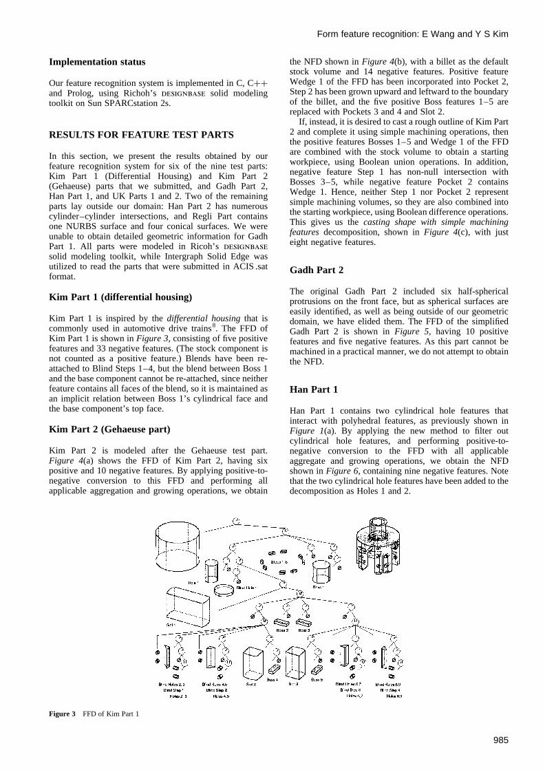
Kim Part 1 is inspired by thedifferential housingthat iscommonly used in automotive drive trains8. The FFD ofKim Part 1 is shown inFigure 3, consisting of five positivefeatures and 33 negative features. (The stock component isnot counted as a positive feature.) Blends have been re-attached to Blind Steps 1–4, but the blend between Boss 1and the base component cannot be re-attached, since neitherfeature contains all faces of the blend, so it is maintained asan implicit relation between Boss 1’s cylindrical face andthe base component’s top face.
Kim Part 2 (Gehaeuse part)
Kim Part 2 is modeled after the Gehaeuse test part.Figure 4(a) shows the FFD of Kim Part 2, having sixpositive and 10 negative features. By applying positive-to-negative conversion to this FFD and performing allapplicable aggregation and growing operations, we obtain
the NFD shown inFigure 4(b), with a billet as the defaultstock volume and 14 negative features. Positive featureWedge 1 of the FFD has been incorporated into Pocket 2,Step 2 has been grown upward and leftward to the boundaryof the billet, and the five positive Boss features 1–5 arereplaced with Pockets 3 and 4 and Slot 2.
If, instead, it is desired to cast a rough outline of Kim Part2 and complete it using simple machining operations, thenthe positive features Bosses 1–5 and Wedge 1 of the FFDare combined with the stock volume to obtain a startingworkpiece, using Boolean union operations. In addition,negative feature Step 1 has non-null intersection withBosses 3–5, while negative feature Pocket 2 containsWedge 1. Hence, neither Step 1 nor Pocket 2 representsimple machining volumes, so they are also combined intothe starting workpiece, using Boolean difference operations.This gives us thecasting shape with simple machiningfeaturesdecomposition, shown inFigure 4(c), with justeight negative features.
Gadh Part 2
The original Gadh Part 2 included six half-sphericalprotrusions on the front face, but as spherical surfaces areeasily identified, as well as being outside of our geometricdomain, we have elided them. The FFD of the simplifiedGadh Part 2 is shown inFigure 5, having 10 positivefeatures and five negative features. As this part cannot bemachined in a practical manner, we do not attempt to obtainthe NFD.
Han Part 1
Han Part 1 contains two cylindrical hole features thatinteract with polyhedral features, as previously shown inFigure 1(a). By applying the new method to filter outcylindrical hole features, and performing positive-to-negative conversion to the FFD with all applicableaggregate and growing operations, we obtain the NFDshown inFigure 6, containing nine negative features. Notethat the two cylindrical hole features have been added to thedecomposition as Holes 1 and 2.
Form feature recognition: E Wang and Y S Kim
985
Figure 3 FFD of Kim Part 1

UK Part 1
UK Part 1 contains numerous pocket and hole features. TheNFD of UK Part 1 is shown inFigure 7, with 28 negativefeatures. Starting from the top-level billet, we recognize atotal of seven through-holes, seven blind holes, seven
pockets, three slots, one blind slot, one step and twoprofiles. Note that Pockets 1, 2 and 5 arebottomlesspockets obtained through aggregation after positive-to-negative conversion, and furthermore that all cylindricaland blending surfaces have been re-attached to all holes,pockets and profiles.
Form feature recognition: E Wang and Y S Kim
986
Figure 4 (a) FFD of Kim Part 2; (b) NFD of Kim Part 2; (c) casting shape with simple machining features for Kim Part 2

Form feature recognition: E Wang and Y S Kim
987
Figure 5 FFD of Gadh Part 2
Figure 6 NFD of Han Part 1
Figure 7 NFD of UK Part 1

UK Part 2
Figure 8shows the FFD of a simplified version of UK Part2, containing two positive and 13 negative features. Theoriginal UK Part 2 contained a few borderline violations ofour geometric domain. Two vertical fillet blends at thejunction of the upper and lower portions of the part weresuch thatdesignbase could not successfully unblend andthen re-create the proper geometry. These two fillets havebeen replaced by unblended edges, which appear in Step 2and Rib 1. Additionally, the original UK Part 2 has acylindrical depression in the right side face of Pocket 1,concentric with Hole 2, that opens onto the inclined face ofPocket 1, and thus does not interact along Pocket 1’sprincipal directions.
FUTURE RESEARCH
We are currently investigating ways to minimize thedetrimental global effects of cutting operations in ASVPdecomposition, new combination operations to improve theconversion to FFD13, support for a wider domain of plane–cylinder interactions in obtaining a polyhedral abstraction ofthe part model, and geometric reasoning for additionalmanufacturing applications. We have completed a pre-liminary implementation of a geometric reasoning methodto generate assembly mating relations suitable for assemblyplanning9, and an incremental updating mechanism forASVP decompositions to support interactive designmodifications10.
We have previously integrated this feature recognitionsystem with a process planning system and applied it tomill-turn parts provided by an industry sponsor11, and arecurrently integrating it with a machining process planning
system to be realistically used in an industrial environment.As part of this latest development effort, we are currentlyre-implementing our system using Visual Cþþ and theACIS 3.0 solid modeling toolkit on Windows NT 4.0.
ACKNOWLEDGEMENTS
This research was supported by the US National ScienceFoundation, the NSF Industry/University CooperativeResearch Center for Machine-Tool Systems at the Univer-sity of Illinois, Caterpillar, Inc., and the Korea Institute ofScience and Technology. The provision ofdesignbase byRicoh Corporation is also greatly appreciated. In addition,the research and implementation of our current featurerecognition method has received contributions fromDouglas Waco, Sreekumar Menon and Fre´deric Pariente´,as well as the authors.
REFERENCES
1. Woo, T. C., Feature extraction by volume decomposition. InProceed-ings of the Conference on CAD/CAM Technology in MechanicalEngineering, Massachusetts, MA, March 1982.
2. Kim, Y. S., Recognition of form features using convex decomposition.Computer-Aided Design, 1992,24(9), 461–476.
3. Waco, D. and Kim, Y. S., Geometric reasoning for machining featuresusing convex decomposition. Computer-Aided Design, 1994,26(6),477–489.
4. Wang, E. and Kim, Y. S., Status of the form feature recognitionmethod using convex decomposition. Presented atASME Computersin Engineering Conference, Sacramento, CA, September 1997.
5. Menon, S. and Kim, Y. S., Cylindrical features in form featurerecognition using convex decomposition. InProceedings of the IFIPConference on Feature Modeling and Recognition in Advanced CAD/CAM Systems, Valenciennes, France, May 1994.
6. Menon, S. and Kim, Y. S., Handling blending features using convexdecomposition. InProceedings of the ASME Computers in Engineer-ing Conference, Vol. 1, Minneapolis, MN, September 1994, pp. 79–92.
7. Waco, D. and Kim, Y. S., Handling interacting positive components inmachining feature reasoning using convex decomposition. Advancesin Engineering Software, 1994,20(2/3), 107–119.
8. Chocholek, S. E., The development of a differential for the manage-ment of traction control. Proceedings of the Institution of MechanicalEngineers, 1988,C368, 75–82.
9. Wang, E. and Kim, Y. S., Feature-based assembly mating reasoning.In Proceedings of the ASME Computer in Engineering Conference,Irvine, CA, August 1996.
10. Pariente´, F. and Kim, Y. S., Incremental and localized update ofconvex decomposition used for form feature recognition. Computer-Aided Design, 1996,28(8), 589–602.
11. Dutta, D., Kim, Y. S., Kim, Y. J., Wang, E. and Yip-Hoi, D., Featureextraction and operation sequencing for machining on mill-turns. Pre-sented atASME Computers in Engineering Conference, Sacramento,CA, September 1997.
12. Kim, Y. S., Volumetric feature recognition using convex decomposi-tion. In Advances in Feature Based Manufacturing, ed. J. Shahet al.Elsevier, Amsterdam, 1994, Ch. 3, pp. 39–63.
13. Wang, E. and Kim, Y. S., Inductive generation of combination opera-tions for form feature recognition using convex decomposition. InProceedings of the 16th International Conference On Computersand Industrial Engineering, March 1994, pp. 317–320.
Form feature recognition: E Wang and Y S Kim
988
Figure 8 FFD of UK Part 2

Eric Wang is a Research Associate at the CAD/CAM Laboratory at theUniversity of Wisconsin–Milwaukee (UWM), and is a Ph.D. candidatein the Computer Science Department of the University of Illinois atUrbana–Champaign. Eric Wang’s research interests include feature-based computer-aided process planning, assembly planning and geo-metric reasoning.
Yong Se Kim is an Associate Professor of Mechanical Engineering atthe University of Wisconsin–Milwaukee (UWM), where he directs theCAD/CAM Laboratory. He joined UWM in 1997. From 1990 to 1997,he was an Assistant Professor at the University of Illinois at Urbana–Champaign. He received his Ph.D. in Mechanical Engineering from theDesign Division of Stanford University in 1990. Yong Se Kim’sresearch interests include computer-integrated design and manufactur-ing, process planning, product development and visual reasoning. He iscurrently the Vice-Chair of Computers and Information in Engineering(CIE) Division of the American Society of Mechanical Engineers(ASME), and will be General Chair for the 2000 ASME CIE Con-ference. Professor Kim is also the Director of International Relationsof the Society of CAD/CAM Engineers in Korea.
Form feature recognition: E Wang and Y S Kim
989