Embed Size (px)
Citation preview
State of Connecticut
Department of Transportation
SUPPLEMENTAL SPECIFICATIONS
TO
THE STANDARD SPECIFICATIONS
FOR
ROADS, BRIDGES AND INCIDENTAL CONSTRUCTION
FORM 816
2004
JULY 2012
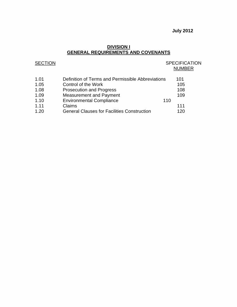
July 2012
DIVISION I GENERAL REQUIREMENTS AND COVENANTS
SECTION SPECIFICATION NUMBER 1.01 Definition of Terms and Permissible Abbreviations 101 1.05 Control of the Work 105 1.08 Prosecution and Progress 108 1.09 Measurement and Payment 109 1.10 Environmental Compliance 110 1.11 Claims 111 1.20 General Clauses for Facilities Construction 120
July 2012
DIVISION II CONSTRUCTION DETAILS
SECTION SPECIFICATION NUMBER 2.02 Roadway Excavation, Formation of Embankment and Disposal of Surplus Material 202 2.05 Trench Excavation 205 3.04 Processed Aggregate Base 304 4.01 Concrete Pavement 401 5.14 Prestressed Concrete Members 514 6.01 Concrete for Structures 601 6.03 Structural Steel 603 6.12 Concrete Cylinder Curing Box 612 6.51 Culverts 651 7.02 Piles 702 8.22 Temporary Precast Concrete Barrier Curb 822 9.10 Metal Beam Rail 910 9.18 Three-Cable Guide Railing (I-Beam Post) and Anchorages 918 9.22 Bituminous Concrete Sidewalk Bituminous Concrete Driveway 922 9.44 Topsoil 944 9.49 Furnishing, Planting and Mulching Trees, Shrubs, Vines and Ground Cover Plants 949 9.75 Mobilization 975 10.01 Trenching and Backfilling 1001 10.10 Concrete Handhole 1010 11.13 Control Cable 1113 12.10 Epoxy Resin Pavement Markings, Symbols and Legends 1210
July 2012
DIVISION III MATERIALS SECTION
SECTION SPECIFICATION NUMBER M.06 Metals M06 M.13 Roadside Development M13 M.16 Traffic Control Signals M16 M.17 Elastomeric Materials M17 M.18 Signing M18
July 2012 STANDARD SPECIFICATIONS
FOR ROADS, BRIDGES AND INCIDENTAL CONSTRUCTION
FORM 816
ERRATA ARTICLE OR LINE PG. SUBARTICLE NO. CORRECTION iv Table of Contents 11 Change “Guild” to “Guide” 4 1.01.01 8 After the end of the definition for “Plans,” insert as a subset, “A. Standard Sheets – Standardized plans containing details approved by the Department and the FHWA, for construction of a given type on any project, included in contracts on an as-needed basis.” 6 1.01.02 41 Change “Aluminum Association” to “Aluminum Association, Inc. (The)” 6 1.01.02 42 Delete “AAA – Aluminum Alloy Association” 7 1.01.02 1 Insert “AABC – Associated Air Balance Council” 7 1.01.02 1 Insert “AAMA – American Architectural Manufacturers Association” 7 1.01.02 12 Insert “ABMA – American Bearing Manufacturers Association” 7 1.01.02 12 Insert “ACGIH – American Council of Government Industrial Hygienists” 7 1.01.02 12 Change “American Concrete Institute” to “ACI International (American Concrete Institute)” 7 1.01.02 14 Insert “ADAAG – Americans with Disabilities Act (ADA) Accessibility Guidelines for Buildings and Facilities” 7 1.01.02 16 Change “Associated General Contractors of America” to “Associated General Contractors of America (The)” 7 1.01.02 19 Insert “AI – Asphalt Institute” 7 1.01.02 19 Change “American Institute of Architects” to “American Institute of Architects (The)” 7 1.01.02 20 Delete “AIEE – American Institute of Electrical Engineers “ 7 1.01.02 24 Delete “ALI – Associated Laboratories, Inc.” 7 1.01.02 26 Change “American Lumber Standard Committee” to “American Lumber Standards Committee, Incorporated” 7 1.01.02 27 Change “Air Movement and Control Association” to “Air Movement and Control Association International, Inc.” 7 1.01.02 31 Delete “AOEC – Area of Environmental Concern” 7 1.01.02 33 Change “The Engineered Wood Association” to “APA-The Engineered Wood Association” 7 1.01.02 37 Change “Air Conditioning” to “Air-Conditioning” 8 1.01.02 7 Change “Air Conditioning” to “Air-Conditioning” 8 1.01.02 8 Change “American Society of Mechanical Engineers” to “ASME International (The American Society of Mechanical Engineers International)” 8 1.01.02 18 Delete “ATA – American Transit Association” 8 1.01.02 20 Delete “AWG – American Wire Gauge” 8 1.01.02 22 Change “Wood-Preservers” to “Wood-Preservers’ “ 8 1.01.02 33 Delete “AZI – American Zinc Institute” 8 1.01.02 35 Change “Building Officials and Code Administrators International” to “BOCA International, Inc.”
ARTICLE OR LINE PG. SUBARTICLE NO. CORRECTION 8 1.01.02 38 Change “Library” to “Laboratory” 9 1.01.02 2 Change “CONNDOT” to “ConnDOT” 9 1.01.02 6 Delete “CPI – Clay Pipe Institute” 9 1.01.02 9 Delete “CS – Commercial Standard” 9 1.01.02 10 Change “Construction Specifications Institute” to “Construction Specifications Institute (The)” 9 1.01.02 12 Change “Tower” to ”Technology” 9 1.01.02 17 Delete “DFPA – Douglas Fir Plywood Association” 9 1.01.02 19 Change “Department of Defense” to “Department of Defense Military Specifications and Standards” 9 1.01.02 21 Change “Association” to “Alliance” 9 1.01.02 23 Delete “U.S. Department of Transportation” 9 1.01.02 28 Delete “U.S. Department of Transportation” 9 1.01.02 30 Insert “FMG – FM Global” 9 1.01.02 31 Delete “U.S. Department of Transportation” 10 1.01.02 2 Delete “HASP – Health and Safety Plan” 10 1.01.02 3 Delete “HMA – Hot Mix Asphalt or Bituminous Concrete” 10 1.01.02 4 Delete “HPMA – Hardwood Plywood Manufacturers Association” 10 1.01.02 5 Insert “HPVA – Hardwood Plywood & Veneer Association” 10 1.01.02 9 Insert “ICC – International Code Council” 10 1.01.02 9 Change “Insulated Cable Engineers Association” to “Insulated Cable Engineers Association, Inc.” 10 1.01.02 10 Change “Institute of Electrical and Electronics Engineers” to “Institute of Electrical and Electronics Engineers, Inc. (The)” 10 1.01.02 21 Change “Military Standardization Documents, U.S. Department of Defense” to “(MILSPEC) Military Specification and Standards” 10 1.01.02 24 Delete “MS – Military Specifications” 10 1.01.02 26 Change “Manufacturers Standardization Society of the Valve and Fittings Industry Inc.” to “Manufacturers Standardization Society of The Valve and Fittings the Valve Industry Inc.” 10 1.01.02 29 Change “National Association of Architectural Metal Manufacturers (The)” to “National Association of Architectural Metal Manufacturers” 10 1.01.02 31 Insert “NADCA – National Air Duct Cleaners Association” 10 1.01.02 34 Delete “NBS – National Bureau of Standards” 10 1.01.02 35 Delete “NC – National Course” 11 1.01.02 3 Delete “NCPRC – National Clay Pipe Research Corporation” 11 1.01.02 10 Change “International Electrical Testing Association” to “InterNational Testing Association” 11 1.01.02 12 Delete “NFS – NFS International” 11 1.01.02 13 Insert “NHLA – National Hardwood Lumber Association” 11 1.01.02 18 Insert “NLGA – National Lumber Grades Authority” 11 1.01.02 18 Delete “NLMA – National Lumber Manufacturers Association” 11 1.01.02 21 Insert “NSF – NSF International” 11 1.01.02 21 Change “National Terrazzo and Mosaic Association (The)” to “National Terrazzo and Mosaic Association, Inc.” 11 1.01.02 26 Delete “PCC – Portland Cement Concrete” 11 1.01.02 28 Delete “PLP – Plastic Laminate Producers” 11 1.01.02 29 Delete “PS – Product Standard of NBS, U.S. Department of Commerce” 11 1.01.02 32 Delete “RLMI – Reflector and Lamp Manufacturers’ Institute”
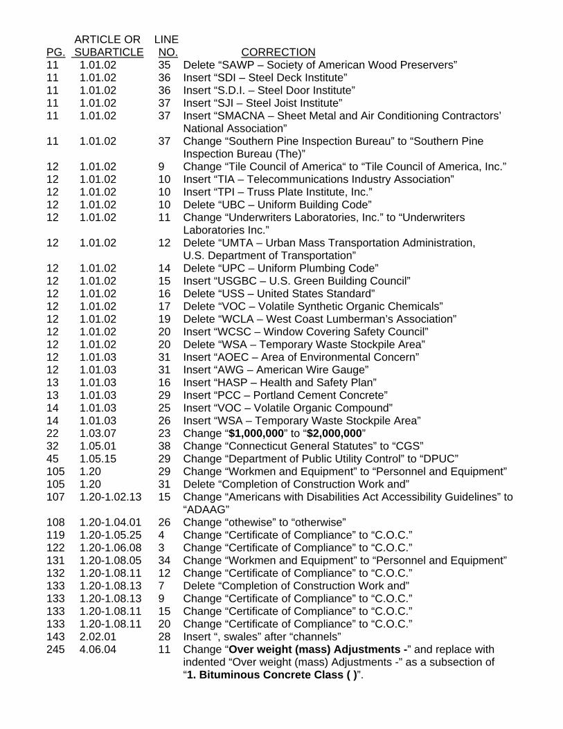
ARTICLE OR LINE PG. SUBARTICLE NO. CORRECTION 11 1.01.02 35 Delete “SAWP – Society of American Wood Preservers” 11 1.01.02 36 Insert “SDI – Steel Deck Institute” 11 1.01.02 36 Insert “S.D.I. – Steel Door Institute” 11 1.01.02 37 Insert “SJI – Steel Joist Institute” 11 1.01.02 37 Insert “SMACNA – Sheet Metal and Air Conditioning Contractors’ National Association” 11 1.01.02 37 Change “Southern Pine Inspection Bureau” to “Southern Pine Inspection Bureau (The)” 12 1.01.02 9 Change “Tile Council of America“ to “Tile Council of America, Inc.” 12 1.01.02 10 Insert “TIA – Telecommunications Industry Association” 12 1.01.02 10 Insert “TPI – Truss Plate Institute, Inc.” 12 1.01.02 10 Delete “UBC – Uniform Building Code” 12 1.01.02 11 Change “Underwriters Laboratories, Inc.” to “Underwriters Laboratories Inc.” 12 1.01.02 12 Delete “UMTA – Urban Mass Transportation Administration, U.S. Department of Transportation” 12 1.01.02 14 Delete “UPC – Uniform Plumbing Code” 12 1.01.02 15 Insert “USGBC – U.S. Green Building Council” 12 1.01.02 16 Delete “USS – United States Standard” 12 1.01.02 17 Delete “VOC – Volatile Synthetic Organic Chemicals” 12 1.01.02 19 Delete “WCLA – West Coast Lumberman’s Association” 12 1.01.02 20 Insert “WCSC – Window Covering Safety Council” 12 1.01.02 20 Delete “WSA – Temporary Waste Stockpile Area” 12 1.01.03 31 Insert “AOEC – Area of Environmental Concern” 12 1.01.03 31 Insert “AWG – American Wire Gauge” 13 1.01.03 16 Insert “HASP – Health and Safety Plan” 13 1.01.03 29 Insert “PCC – Portland Cement Concrete” 14 1.01.03 25 Insert “VOC – Volatile Organic Compound” 14 1.01.03 26 Insert “WSA – Temporary Waste Stockpile Area” 22 1.03.07 23 Change “$1,000,000” to “$2,000,000” 32 1.05.01 38 Change “Connecticut General Statutes” to “CGS” 45 1.05.15 29 Change “Department of Public Utility Control” to “DPUC” 105 1.20 29 Change “Workmen and Equipment” to “Personnel and Equipment” 105 1.20 31 Delete “Completion of Construction Work and” 107 1.20-1.02.13 15 Change “Americans with Disabilities Act Accessibility Guidelines” to “ADAAG” 108 1.20-1.04.01 26 Change “othewise” to “otherwise” 119 1.20-1.05.25 4 Change “Certificate of Compliance” to “C.O.C.” 122 1.20-1.06.08 3 Change “Certificate of Compliance” to “C.O.C.” 131 1.20-1.08.05 34 Change “Workmen and Equipment” to “Personnel and Equipment” 132 1.20-1.08.11 12 Change “Certificate of Compliance” to “C.O.C.” 133 1.20-1.08.13 7 Delete “Completion of Construction Work and” 133 1.20-1.08.13 9 Change “Certificate of Compliance” to “C.O.C.” 133 1.20-1.08.11 15 Change “Certificate of Compliance” to “C.O.C.” 133 1.20-1.08.11 20 Change “Certificate of Compliance” to “C.O.C.” 143 2.02.01 28 Insert “, swales” after “channels” 245 4.06.04 11 Change “Over weight (mass) Adjustments -” and replace with indented “Over weight (mass) Adjustments -” as a subsection of “1. Bituminous Concrete Class ( )”.
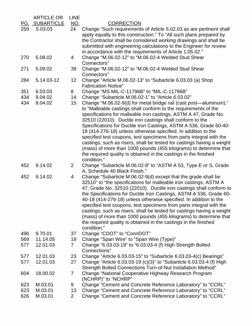
ARTICLE OR LINE PG. SUBARTICLE NO. CORRECTION 259 5.03.03 24 Change “Such requirements of Article 5.02.03 as are pertinent shall
apply equally to this construction.” To “All such plans prepared by the Contractor shall be considered working drawings and shall be submitted with engineering calculations to the Engineer for review in accordance with the requirements of Article 1.05.02."
270 5.08.02 4 Change “M.06.02-12” to “M.06.02-4 Welded Stud Shear Connectors”
271 5.09.02 39 Change “M.06.02-12” to “M.06.02-4 Welded Stud Shear Connectors”
284 5.14.03-12 12 Change “Article M.06.02-13” to “Subarticle 6.03.03 (a) Shop Fabrication Notice”
351 6.03.03 8 Change “MS MIL-C-11796B” to “MIL-C-11796B” 434 9.04.02 14 Change “Subarticle M.06.02-1” to “Article 6.03.02” 434 9.04.02 15 Change “M.06.02-9(d) for metal bridge rail (cast post—aluminum).”
to “Malleable castings shall conform to the requirements of the specifications for malleable iron castings, ASTM A 47, Grade No. 32510 (22010). Ductile iron castings shall conform to the Specifications for Ductile Iron Castings, ASTM A 536, Grade 60-40-18 (414-276-18) unless otherwise specified. In addition to the specified test coupons, test specimens from parts integral with the castings, such as risers, shall be tested for castings having a weight (mass) of more than 1000 pounds (455 kilograms) to determine that the required quality is obtained in the castings in the finished condition.”
452 9.14.02 2 Change “Subarticle M.06.02-8” to “ASTM A 53, Type E or S, Grade A, Schedule 40 Black Finish.”
452 9.14.02 4 Change “Subarticle M.06.02-9(d) except that the grade shall be 32510” to “the specifications for malleable iron castings, ASTM A 47, Grade No. 32510 (22010). Ductile iron castings shall conform to the Specifications for Ductile Iron Castings, ASTM A 536, Grade 60-40-18 (414-276-18) unless otherwise specified. In addition to the specified test coupons, test specimens from parts integral with the castings, such as risers, shall be tested for castings having a weight (mass) of more than 1000 pounds (455 kilograms) to determine that the required quality is obtained in the castings in the finished condition.”
496 9.70.01 37 Change “CDOT” to “ConnDOT” 569 11.14.05 19 Change “Span Wire” to “Span Wire (Type)” 577 12.01.03 7 Change “6.03.03-19” to “6.03.03-4 (f) High Strength Bolted
Connections” 577 12.01.03 23 Change “Article 6.03.03-15” to “Subarticle 6.03.03-4(c) Bearings” 577 12.01.03 27 Change “Article 6.03.03-19 (c)(3)” to “Subarticle 6.03.03-4 (f) High
Strength Bolted Connections Turn-of-Nut Installation Method” 604 18.00.02 7 Change “National Cooperative Highway Research Program (NCHRP)” to “NCHRP” 623 M.03.01 9 Change “Cement and Concrete Reference Laboratory” to “CCRL” 623 M.03.01 13 Change “Cement and Concrete Reference Laboratory” to “CCRL” 626 M.03.01 2 Change “Cement and Concrete Reference Laboratory” to “CCRL”

ARTICLE OR LINE PG. SUBARTICLE NO. CORRECTION 626 M.03.01 3 Change “NBS” to “NIST” 632 M.03.01 18 Change “Cement and Concrete Reference Laboratory” to “CCRL” 638 M.04.02 37 Change “Asphalt Institute’s” to “AI’s” 711 M.10.02-1 17 Change “Subarticle M.06.02-1(b)” to “Article M.06.02” 720 M.10.08-3 2 Change “Subarticle M.06.02-1(b)” to “Article M.06.02” 735 M.13.03 22 Change “AOAC International” to “AOAC” 760 M.15.15 21 Change “non-fusible” to “fused” 780 M.16.08 41 Change “Americans With Disabilities Act (ADA)” to “ADA” 790 M.16.10 24 Change “Underwriter’s Laboratory” to “UL” 800 M.17.01 19 Change “AAA 6061-T6” to “AA 6061-T6” 837 Pay Items 24 Change “Span Wire” to “Span Wire (Type)” 845 Index 6 Add page 133 to “Acceptance of Project” 846 Index 13 Add page 107 to “Bids: Consideration of” 847 Index 28 Add page 132 to “Cleaning Up, Final” 849 Index 25 Add page 107 to “Consideration of Bids” 849 Index 39 Add page 108 to “Contract: Intent of” 850 Index 3 Add page 133 to “Contractor’s: Responsibility, Termination of the” 850 Index 13 Add page 114 to “Cooperation by Contractor” 850 Index 15 Add page 114 to “Coordination of Special Provisions, Plans, Supplemental Specifications and Standard Specifications and Other Contract Requirements” 850 Index 40 Add page 128 to “Cutting and Patching:” 852 Index 16 Add page 106 to “Examination of Plans, Specifications, Special Provisions and Site of Work” 852 Index 38 Insert “Facilities, Temporary…126” 853 Index 7 Add page 132 to “Final: Cleaning Up” 854 Index 35 Add page 115 to “Inspection” 855 Index 11 Add page 108 to “Intent of Contract” 855 Index 22 Add page 106 to “Knowledge of Applicable Laws” 855 Index 25 Add page 106 to “Laws: Knowledge of Applicable” 856 Index 27 Add page 120 to “Materials: Source of Supply and Quality” 856 Index 28 Add page 121 to “Materials: Storage of” 857 Index 33 Add page 133 to “Operation and Maintenance Manuals:” 857 Index 34 Change page 133 to 136 for “Equipment and Systems Maintenance Manual” 859 Index 2 Add page 131 to “Personnel and Equipment” 860 Index 6 Add page 114 to “Plans: Coordination of Special Provisions, Supplemental Specifications and Standard Specifications and Other Contract Requirements” 860 Index 7 Add page 106 to “Plans: Examination of” 860 Index 30 Change page 108 to 112 for “Product Data” 860 Index 31 Change page 108 to 112 for “Product Samples “ 860 Index 32 Add page 124 to “Product Selection:” 861 Index 12 Add page 126 to “Prosecution of Work” 861 Index 38 Change page 115 to 135 for “Record Drawings” 863 Index 3 Add page 125 to “Sanitary Provisions” 863 Index 18 Insert “Services, Temporary…126” 863 Index 23 Add page 111 to “Shop Drawings” 864 Index 4 Add page 106 to “Site of Work, Examination of”
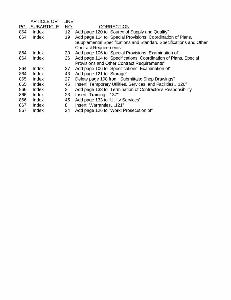
ARTICLE OR LINE PG. SUBARTICLE NO. CORRECTION 864 Index 12 Add page 120 to “Source of Supply and Quality” 864 Index 19 Add page 114 to “Special Provisions: Coordination of Plans, Supplemental Specifications and Standard Specifications and Other Contract Requirements” 864 Index 20 Add page 106 to “Special Provisions: Examination of” 864 Index 26 Add page 114 to “Specifications: Coordination of Plans, Special Provisions and Other Contract Requirements” 864 Index 27 Add page 106 to “Specifications: Examination of” 864 Index 43 Add page 121 to “Storage” 865 Index 27 Delete page 108 from “Submittals: Shop Drawings” 865 Index 45 Insert “Temporary Utilities, Services, and Facilities…126” 866 Index 2 Add page 133 to “Termination of Contractor’s Responsibility” 866 Index 23 Insert “Training…137” 866 Index 45 Add page 133 to “Utility Services” 867 Index 8 Insert “Warranties…121” 867 Index 24 Add page 126 to “Work: Prosecution of”
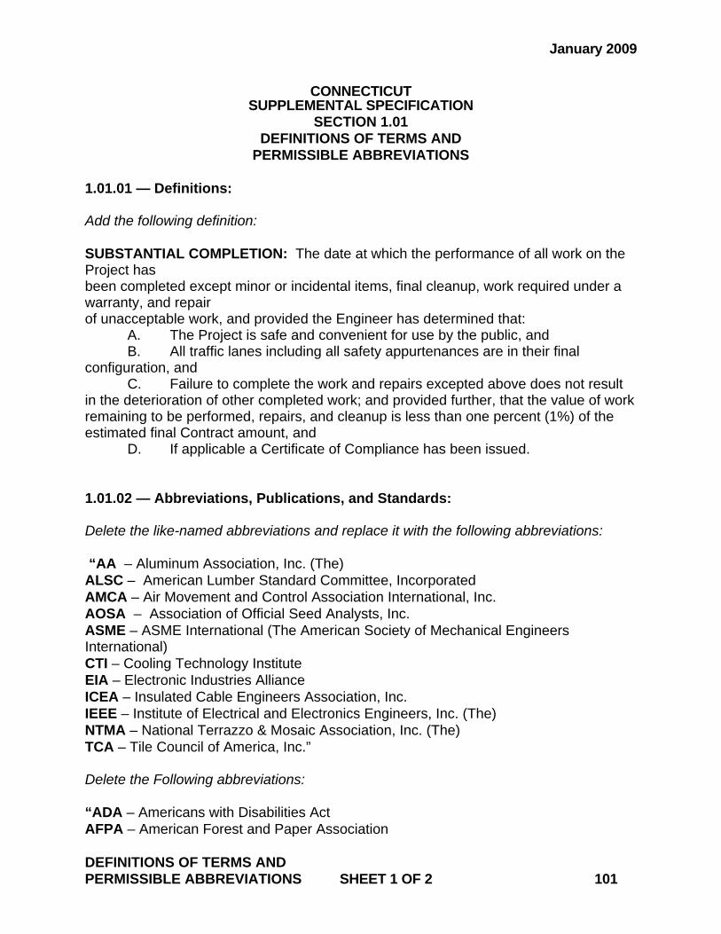
January 2009
CONNECTICUT SUPPLEMENTAL SPECIFICATION
SECTION 1.01 DEFINITIONS OF TERMS AND
PERMISSIBLE ABBREVIATIONS 1.01.01 — Definitions: Add the following definition: SUBSTANTIAL COMPLETION: The date at which the performance of all work on the Project has been completed except minor or incidental items, final cleanup, work required under a warranty, and repair of unacceptable work, and provided the Engineer has determined that: A. The Project is safe and convenient for use by the public, and B. All traffic lanes including all safety appurtenances are in their final configuration, and C. Failure to complete the work and repairs excepted above does not result in the deterioration of other completed work; and provided further, that the value of work remaining to be performed, repairs, and cleanup is less than one percent (1%) of the estimated final Contract amount, and D. If applicable a Certificate of Compliance has been issued. 1.01.02 — Abbreviations, Publications, and Standards: Delete the like-named abbreviations and replace it with the following abbreviations: “AA – Aluminum Association, Inc. (The) ALSC – American Lumber Standard Committee, Incorporated AMCA – Air Movement and Control Association International, Inc. AOSA – Association of Official Seed Analysts, Inc. ASME – ASME International (The American Society of Mechanical Engineers International) CTI – Cooling Technology Institute EIA – Electronic Industries Alliance ICEA – Insulated Cable Engineers Association, Inc. IEEE – Institute of Electrical and Electronics Engineers, Inc. (The) NTMA – National Terrazzo & Mosaic Association, Inc. (The) TCA – Tile Council of America, Inc.” Delete the Following abbreviations: “ADA – Americans with Disabilities Act AFPA – American Forest and Paper Association DEFINITIONS OF TERMS AND PERMISSIBLE ABBREVIATIONS SHEET 1 OF 2 101
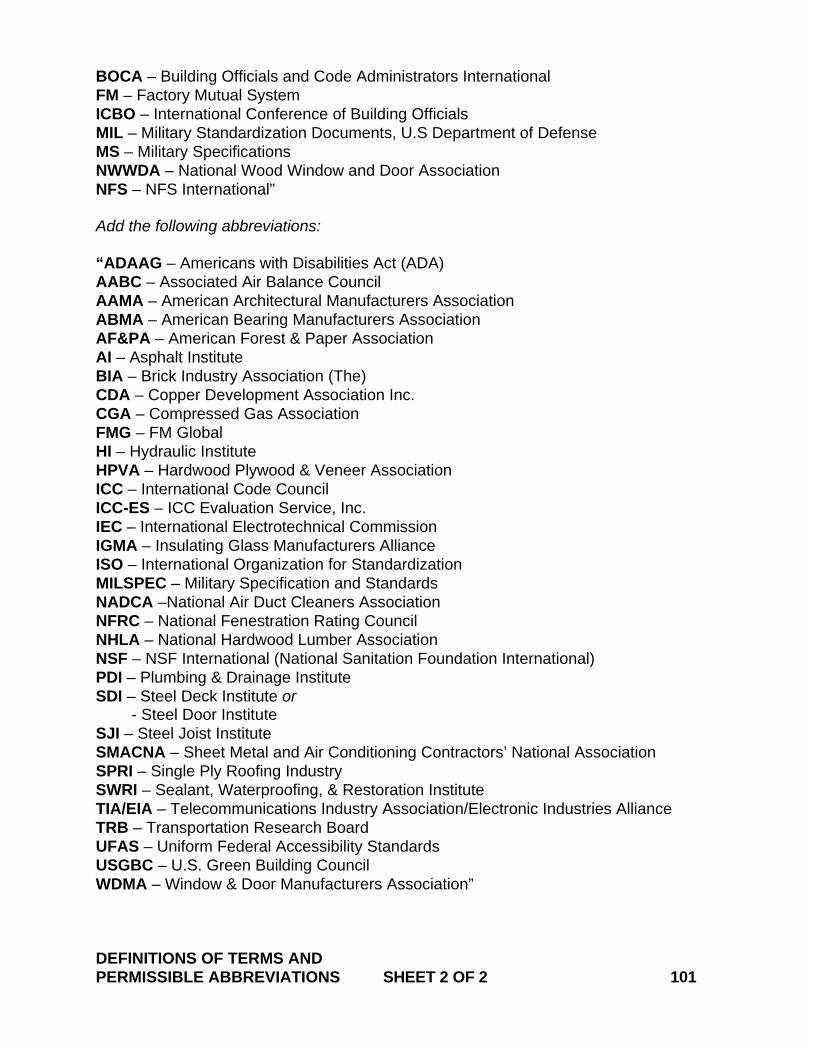
BOCA – Building Officials and Code Administrators International FM – Factory Mutual System ICBO – International Conference of Building Officials MIL – Military Standardization Documents, U.S Department of Defense MS – Military Specifications NWWDA – National Wood Window and Door Association NFS – NFS International” Add the following abbreviations: “ADAAG – Americans with Disabilities Act (ADA) AABC – Associated Air Balance Council AAMA – American Architectural Manufacturers Association ABMA – American Bearing Manufacturers Association AF&PA – American Forest & Paper Association AI – Asphalt Institute BIA – Brick Industry Association (The) CDA – Copper Development Association Inc. CGA – Compressed Gas Association FMG – FM Global HI – Hydraulic Institute HPVA – Hardwood Plywood & Veneer Association ICC – International Code Council ICC-ES – ICC Evaluation Service, Inc. IEC – International Electrotechnical Commission IGMA – Insulating Glass Manufacturers Alliance ISO – International Organization for Standardization MILSPEC – Military Specification and Standards NADCA –National Air Duct Cleaners Association NFRC – National Fenestration Rating Council NHLA – National Hardwood Lumber Association NSF – NSF International (National Sanitation Foundation International) PDI – Plumbing & Drainage Institute SDI – Steel Deck Institute or - Steel Door Institute SJI – Steel Joist Institute SMACNA – Sheet Metal and Air Conditioning Contractors’ National Association SPRI – Single Ply Roofing Industry SWRI – Sealant, Waterproofing, & Restoration Institute TIA/EIA – Telecommunications Industry Association/Electronic Industries Alliance TRB – Transportation Research Board UFAS – Uniform Federal Accessibility Standards USGBC – U.S. Green Building Council WDMA – Window & Door Manufacturers Association” DEFINITIONS OF TERMS AND PERMISSIBLE ABBREVIATIONS SHEET 2 OF 2 101
July 2012
CONNECTICUT SUPPLEMENTAL SPECIFICATION
SECTION 1.05 CONTROL OF THE WORK
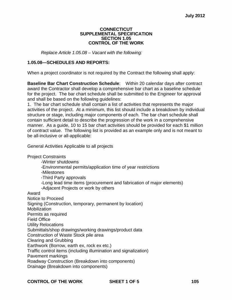
Replace Article 1.05.08 – Vacant with the following: 1.05.08—SCHEDULES AND REPORTS: When a project coordinator is not required by the Contract the following shall apply: Baseline Bar Chart Construction Schedule: Within 20 calendar days after contract award the Contractor shall develop a comprehensive bar chart as a baseline schedule for the project. The bar chart schedule shall be submitted to the Engineer for approval and shall be based on the following guidelines: 1. The bar chart schedule shall contain a list of activities that represents the major activities of the project. At a minimum, this list should include a breakdown by individual structure or stage, including major components of each. The bar chart schedule shall contain sufficient detail to describe the progression of the work in a comprehensive manner. As a guide, 10 to 15 bar chart activities should be provided for each $1 million of contract value. The following list is provided as an example only and is not meant to be all-inclusive or all-applicable: General Activities Applicable to all projects Project Constraints -Winter shutdowns -Environmental permits/application time of year restrictions -Milestones -Third Party approvals -Long lead time items (procurement and fabrication of major elements) -Adjacent Projects or work by others Award Notice to Proceed Signing (Construction, temporary, permanent by location) Mobilization Permits as required Field Office Utility Relocations Submittals/shop drawings/working drawings/product data Construction of Waste Stock pile area Clearing and Grubbing Earthwork (Borrow, earth ex, rock ex etc.) Traffic control items (including illumination and signalization) Pavement markings Roadway Construction (Breakdown into components) Drainage (Breakdown into components) CONTROL OF THE WORK SHEET 1 OF 5 105
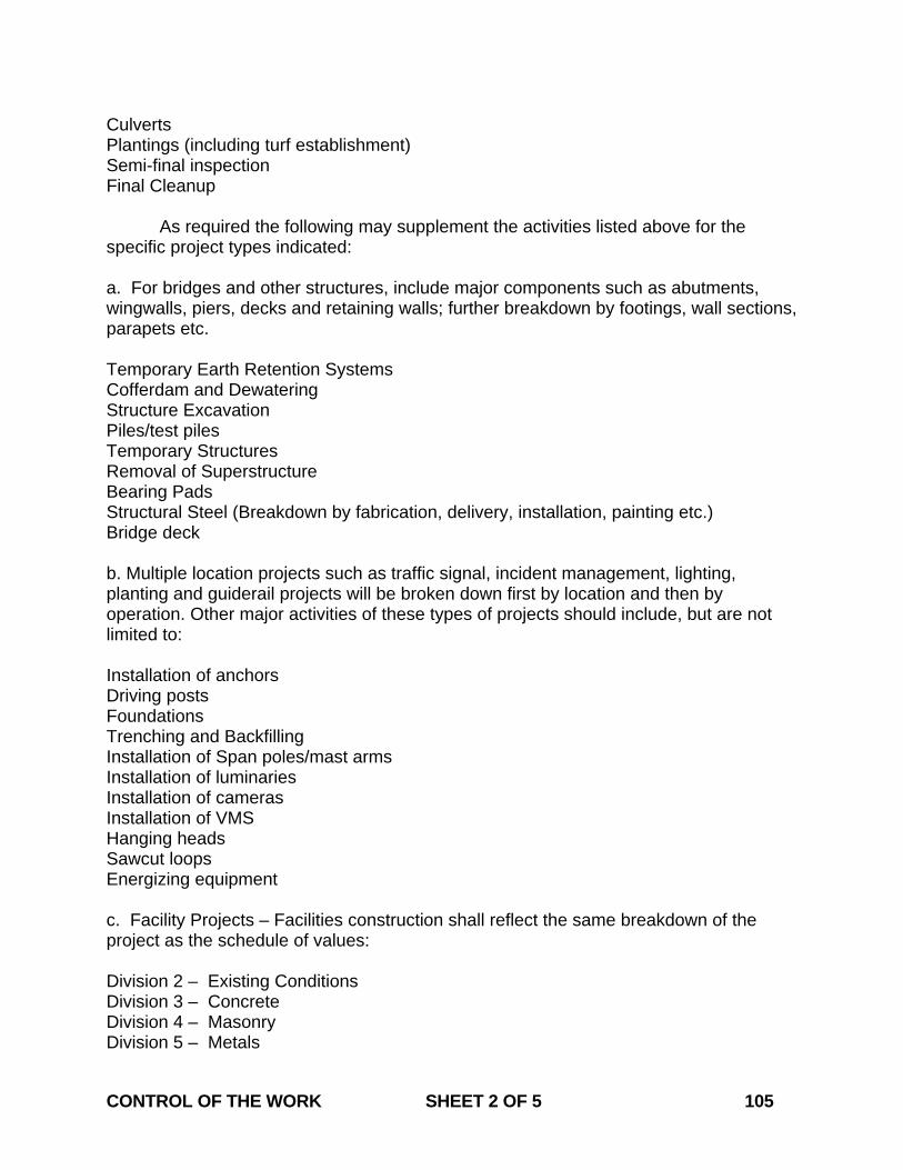
Culverts Plantings (including turf establishment) Semi-final inspection Final Cleanup As required the following may supplement the activities listed above for the specific project types indicated: a. For bridges and other structures, include major components such as abutments, wingwalls, piers, decks and retaining walls; further breakdown by footings, wall sections, parapets etc. Temporary Earth Retention Systems Cofferdam and Dewatering Structure Excavation Piles/test piles Temporary Structures Removal of Superstructure Bearing Pads Structural Steel (Breakdown by fabrication, delivery, installation, painting etc.) Bridge deck b. Multiple location projects such as traffic signal, incident management, lighting, planting and guiderail projects will be broken down first by location and then by operation. Other major activities of these types of projects should include, but are not limited to: Installation of anchors Driving posts Foundations Trenching and Backfilling Installation of Span poles/mast arms Installation of luminaries Installation of cameras Installation of VMS Hanging heads Sawcut loops Energizing equipment c. Facility Projects – Facilities construction shall reflect the same breakdown of the project as the schedule of values: Division 2 – Existing Conditions Division 3 – Concrete Division 4 – Masonry Division 5 – Metals CONTROL OF THE WORK SHEET 2 OF 5 105
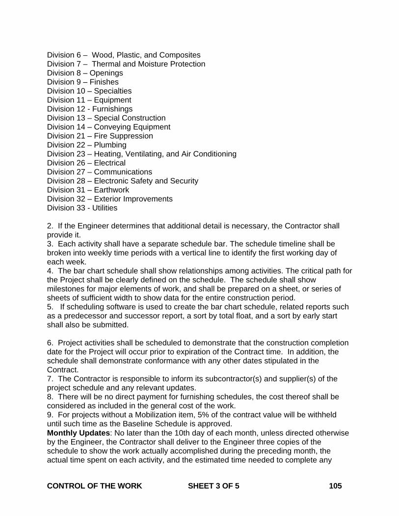
Division 6 – Wood, Plastic, and Composites Division 7 – Thermal and Moisture Protection Division 8 – Openings Division 9 – Finishes Division 10 – Specialties Division 11 – Equipment Division 12 - Furnishings Division 13 – Special Construction Division 14 – Conveying Equipment Division 21 – Fire Suppression Division 22 – Plumbing Division 23 – Heating, Ventilating, and Air Conditioning Division 26 – Electrical Division 27 – Communications Division 28 – Electronic Safety and Security Division 31 – Earthwork Division 32 – Exterior Improvements Division 33 - Utilities 2. If the Engineer determines that additional detail is necessary, the Contractor shall provide it. 3. Each activity shall have a separate schedule bar. The schedule timeline shall be broken into weekly time periods with a vertical line to identify the first working day of each week. 4. The bar chart schedule shall show relationships among activities. The critical path for the Project shall be clearly defined on the schedule. The schedule shall show milestones for major elements of work, and shall be prepared on a sheet, or series of sheets of sufficient width to show data for the entire construction period. 5. If scheduling software is used to create the bar chart schedule, related reports such as a predecessor and successor report, a sort by total float, and a sort by early start shall also be submitted. 6. Project activities shall be scheduled to demonstrate that the construction completion date for the Project will occur prior to expiration of the Contract time. In addition, the schedule shall demonstrate conformance with any other dates stipulated in the Contract. 7. The Contractor is responsible to inform its subcontractor(s) and supplier(s) of the project schedule and any relevant updates. 8. There will be no direct payment for furnishing schedules, the cost thereof shall be considered as included in the general cost of the work. 9. For projects without a Mobilization item, 5% of the contract value will be withheld until such time as the Baseline Schedule is approved. Monthly Updates: No later than the 10th day of each month, unless directed otherwise by the Engineer, the Contractor shall deliver to the Engineer three copies of the schedule to show the work actually accomplished during the preceding month, the actual time spent on each activity, and the estimated time needed to complete any CONTROL OF THE WORK SHEET 3 OF 5 105

activity which has been started but not completed. Each time bar shall indicate, in 10% increments, the estimated percentage of that activity which remains to be completed. As the Project progresses, the Contractor shall place a contrasting mark in each bar to indicate the actual percentage of the activity that has been completed. The monthly update shall include revisions of the schedule necessitated by revisions to the Project directed by the Engineer (including, but not limited to extra work), during the month preceding the update. Similarly, any changes of the schedule required due to changes in the Contractor’s planning or progress shall also be included. The Engineer reserves the right to reject any such revisions. If the schedule revisions extend the contract completion date, due to extra or added work or delays beyond the control of the Contractor, the Contractor shall submit a request in writing for an extension of time in accordance with Article 1.08.08. This request shall be supported by an analysis of the schedules submitted previously. Any schedule revisions shall be identified and explained in a cover letter accompanying the monthly update. The letter shall also describe in general terms the progress of the Project since the last schedule update and shall identify any items of special interest. If the Contractor fails to provide monthly schedule updates, the Engineer has the right to hold 10% of the monthly estimated payment, or $5,000, whichever is less, until such time as an update has been provided in accordance with this provision. Biweekly Schedules: Each week, the Contractor shall submit to the Engineer a two week look-ahead schedule. This short-term schedule may be handwritten but shall clearly indicate all work planned for the following two week period. Recovery Schedules: If the updated schedule indicates that the Project has fallen behind schedule, the Contractor shall either submit a time extension request in accordance with 1.08.08 or immediately institute steps acceptable to the Engineer to improve its progress of the Project. In such a case, the Contractor shall submit a recovery plan, as may be deemed necessary by the Engineer, to demonstrate the manner in which an acceptable rate of progress will be regained. Replace the first paragraph of Article 1.05.12 – Payrolls with the following: For each week of the Project from the first week during which an employee of the Contractor does Project work to which prevailing wage requirements apply, until the last week on which such an employee does such work, the Contractor shall furnish to the Engineer certified copies of payrolls showing (a) the names of the employees who worked on the Project and whose work is subject to prevailing wage requirements, (b) the specific days and hours and numbers of hours that each such employee worked on the Project, and (c) the amount of money paid to each such employee for Project work. Each such payroll shall include the statement(s) of compliance with prevailing wage laws required by the State of Connecticut and, if applicable, by the Federal government. Said payrolls must contain all information required by Connecticut General Statutes Section 31-53 (as it may be revised). For contracts subject to Federal prevailing wage requirements, each payroll shall also contain the information required by the Davis Bacon and Related Acts (DBR). All of the payroll requirements in this Article shall also apply to the work of any subcontractor or other party that performs work on the Project site, and the Contractor shall be responsible for ensuring that each such party meets said requirements. CONTROL OF THE WORK SHEET 4 OF 5 105
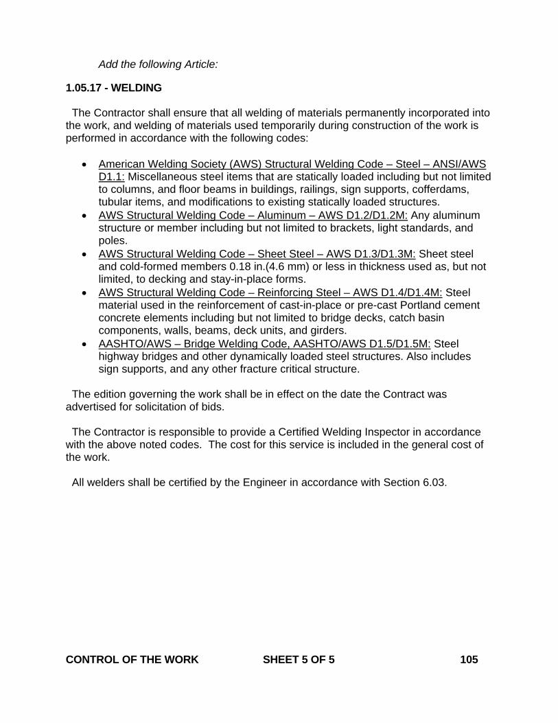
Add the following Article: 1.05.17 - WELDING The Contractor shall ensure that all welding of materials permanently incorporated into the work, and welding of materials used temporarily during construction of the work is performed in accordance with the following codes:
• American Welding Society (AWS) Structural Welding Code – Steel – ANSI/AWS D1.1: Miscellaneous steel items that are statically loaded including but not limited to columns, and floor beams in buildings, railings, sign supports, cofferdams, tubular items, and modifications to existing statically loaded structures.
• AWS Structural Welding Code – Aluminum – AWS D1.2/D1.2M: Any aluminum structure or member including but not limited to brackets, light standards, and poles.
• AWS Structural Welding Code – Sheet Steel – AWS D1.3/D1.3M: Sheet steel and cold-formed members 0.18 in.(4.6 mm) or less in thickness used as, but not limited, to decking and stay-in-place forms.
• AWS Structural Welding Code – Reinforcing Steel – AWS D1.4/D1.4M: Steel material used in the reinforcement of cast-in-place or pre-cast Portland cement concrete elements including but not limited to bridge decks, catch basin components, walls, beams, deck units, and girders.
• AASHTO/AWS – Bridge Welding Code, AASHTO/AWS D1.5/D1.5M: Steel highway bridges and other dynamically loaded steel structures. Also includes sign supports, and any other fracture critical structure.
The edition governing the work shall be in effect on the date the Contract was advertised for solicitation of bids. The Contractor is responsible to provide a Certified Welding Inspector in accordance with the above noted codes. The cost for this service is included in the general cost of the work. All welders shall be certified by the Engineer in accordance with Section 6.03. CONTROL OF THE WORK SHEET 5 OF 5 105

July 2012
CONNECTICUT SUPPLEMENTAL SPECIFICATION
SECTION 1.08 PROSECUTION AND PROGRESS
Article 1.08.01 – Transfer of Work or Contract: Replace the last paragraph with the following: The Contractor shall not sublet, sell, transfer, assign, or otherwise dispose of the Contract or any portion thereof, or of the work provided for therein, or of its right, title, or interest therein, to any individual or entity without the written consent of the Commissioner. No payment will be made for such work until written consent is provided by the Commissioner. Article 1.08.07 – Determination of Contract Time: Replace the fifth paragraph with the following: The total elapsed time in calendar days, computed as described above, from the commencement date specified in the Engineer's "Notice to Proceed" to the “Substantial Completion” date specified in the Engineer's "Notice of Substantial Completion" shall be considered as the time used in the performance of the Contract work. Article 1.08.09 – Failure to Complete Work on Time: Replace the second paragraph with the following: If the last day of the initial Contract time or the initial Contract date determined for Substantial Completion is before December 1 in the given year, liquidated damages as specified in the Contract shall be assessed against the Contractor per calendar day (including any days during a winter shutdown period) from that day until the date on which the Project is substantially completed.
1.08.12—Final Inspection: Replace the first paragraph with the following: If the Engineer determines that the work may be substantially complete, a Semi Final Inspection will be held as soon as practical. After the Semi Final Inspection is held and the Engineer determines that the requirements for Substantial Completion have been satisfied the Engineer will prepare a “Notice of Substantial Completion”.
PROSECUTION AND PROGRESS SHEET 1 OF 2 108
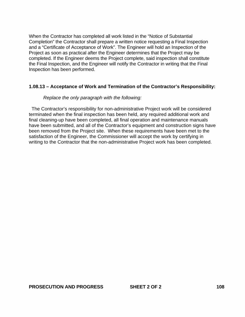
When the Contractor has completed all work listed in the “Notice of Substantial Completion” the Contractor shall prepare a written notice requesting a Final Inspection and a “Certificate of Acceptance of Work”. The Engineer will hold an Inspection of the Project as soon as practical after the Engineer determines that the Project may be completed. If the Engineer deems the Project complete, said inspection shall constitute the Final Inspection, and the Engineer will notify the Contractor in writing that the Final Inspection has been performed.
1.08.13 – Acceptance of Work and Termination of the Contractor’s Responsibility: Replace the only paragraph with the following: The Contractor’s responsibility for non-administrative Project work will be considered terminated when the final inspection has been held, any required additional work and final cleaning-up have been completed, all final operation and maintenance manuals have been submitted, and all of the Contractor’s equipment and construction signs have been removed from the Project site. When these requirements have been met to the satisfaction of the Engineer, the Commissioner will accept the work by certifying in writing to the Contractor that the non-administrative Project work has been completed. PROSECUTION AND PROGRESS SHEET 2 OF 2 108
January 2009
CONNECTICUT SUPPLEMENTAL SPECIFICATION
SECTION 1.09 MEASUREMENT AND PAYMENT
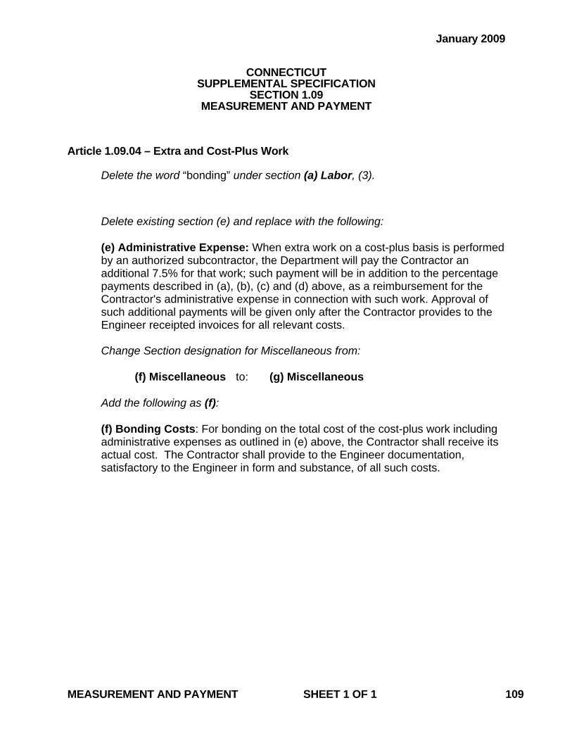
Article 1.09.04 – Extra and Cost-Plus Work Delete the word “bonding” under section (a) Labor, (3).
Delete existing section (e) and replace with the following: (e) Administrative Expense: When extra work on a cost-plus basis is performed by an authorized subcontractor, the Department will pay the Contractor an additional 7.5% for that work; such payment will be in addition to the percentage payments described in (a), (b), (c) and (d) above, as a reimbursement for the Contractor's administrative expense in connection with such work. Approval of such additional payments will be given only after the Contractor provides to the Engineer receipted invoices for all relevant costs. Change Section designation for Miscellaneous from:
(f) Miscellaneous to: (g) Miscellaneous
Add the following as (f):
(f) Bonding Costs: For bonding on the total cost of the cost-plus work including administrative expenses as outlined in (e) above, the Contractor shall receive its actual cost. The Contractor shall provide to the Engineer documentation, satisfactory to the Engineer in form and substance, of all such costs.
MEASUREMENT AND PAYMENT SHEET 1 OF 1 109
January 2007
CONNECTICUT SUPPLEMENTAL SPECIFICATION
SECTION 1.10 ENVIRONMENTAL COMPLIANCE
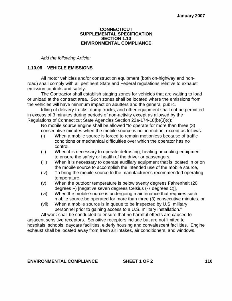
Add the following Article: 1.10.08 – VEHICLE EMISSIONS
All motor vehicles and/or construction equipment (both on-highway and non-road) shall comply with all pertinent State and Federal regulations relative to exhaust emission controls and safety.
The Contractor shall establish staging zones for vehicles that are waiting to load or unload at the contract area. Such zones shall be located where the emissions from the vehicles will have minimum impact on abutters and the general public.
Idling of delivery trucks, dump trucks, and other equipment shall not be permitted in excess of 3 minutes during periods of non-activity except as allowed by the Regulations of Connecticut State Agencies Section 22a-174-18(b)(3)(c):
No mobile source engine shall be allowed “to operate for more than three (3) consecutive minutes when the mobile source is not in motion, except as follows: (i) When a mobile source is forced to remain motionless because of traffic
conditions or mechanical difficulties over which the operator has no control,
(ii) When it is necessary to operate defrosting, heating or cooling equipment to ensure the safety or health of the driver or passengers,
(iii) When it is necessary to operate auxiliary equipment that is located in or on the mobile source to accomplish the intended use of the mobile source,
(iv) To bring the mobile source to the manufacturer’s recommended operating temperature,
(v) When the outdoor temperature is below twenty degrees Fahrenheit (20 degrees F) [negative seven degrees Celsius (-7 degrees C)],
(vi) When the mobile source is undergoing maintenance that requires such mobile source be operated for more than three (3) consecutive minutes, or
(vii) When a mobile source is in queue to be inspected by U.S. military personnel prior to gaining access to a U.S. military installation.”
All work shall be conducted to ensure that no harmful effects are caused to adjacent sensitive receptors. Sensitive receptors include but are not limited to hospitals, schools, daycare facilities, elderly housing and convalescent facilities. Engine exhaust shall be located away from fresh air intakes, air conditioners, and windows.
ENVIRONMENTAL COMPLIANCE SHEET 1 OF 2 110
A Vehicle Emissions Mitigation plan will be required for areas where extensive
work will be performed within (less than 50 feet (15 meters)) to sensitive receptors. No work will proceed until a sequence of construction and a Vehicle Emissions Mitigation plan is submitted in writing to the Engineer for review and all comments are addressed in a manner acceptable to the Engineer. The mitigation plan must address the control of vehicle emissions from all vehicles and construction equipment.
Any costs associated with this “Vehicle Emissions” article shall be included in the general cost of the Contract. In addition, there shall be no time granted to the contractor for compliance with this notice. The contractor’s compliance with this notice and any associated regulations shall not be grounds for claims as outlined in Section 1.11 – “Claims”.
ENVIRONMENTAL COMPLIANCE SHEET 2 OF 2 110
July 2010
CONNECTICUT SUPPLEMENTAL SPECIFICATION
SECTION 1.11 CLAIMS
Add the following Section: 1.11.01 – General: When filing a formal claim under Section 4-61 (referred to as “Section 4-61” below) of the C.G.S. (as revised), either as a lawsuit in the Superior Court or as a demand for arbitration, the Contractor must follow the procedures and comply with the requirements set forth in this Section of the Specifications. This Section does not, unless so specified, govern informal claims for additional compensation which the Contractor may bring before the Department. The Contractor should understand, however, that the Department may need, before the Department can resolve such a claim, the same kinds of documentation and other substantiation that it requires under this Section. It is the intent of the Department to compensate the Contractor for actual increased costs caused by or arising from acts or omissions on the part of the Department that violate legal or contractual duties owed to the Contractor by the Department. 1.11.02 – Notice of Claim: Whenever the Contractor intends to file a formal claim against the Department under Section 4-61, seeking compensation for additional costs, the Contractor shall notify the Commissioner in writing (in strict compliance with Section 4-61) of the details of said claim. Such written notice shall contain all pertinent information described in Article 1.11.05 below. Once formal notice of a claim under C.G.S. Section 4-61 (b) (as revised) has been given to the Commissioner, the claimant may not change the claim in any way, in either concept or monetary amount, (1) without filing a new notice of claim and demand for arbitration to reflect any such change and (2) without the minimum period of six months after filing of the new demand commencing again and running before any hearing on the merits of the claim may be held. The only exception to this limitation will be for damages that continue to accrue after submission of the notice, in ways described and anticipated in the notice. 1.11.03 – Record Keeping: The Contractor shall keep daily records of all costs incurred in connection with its construction-related activities on behalf of the Department. These daily records shall identify each aspect of the Project affected by matters related to any claim for additional compensation that the Contractor has filed, intends to file, or has reason to believe that it may file against the Department; the specific Project locations where Project work has been so affected; the number of people working on the affected aspects of the Project at the pertinent time(s); and the types and number of pieces of equipment on the Project site at the pertinent time(s). If possible, any potential or anticipated effect on the Project’s progress or schedule which may result in a claim by the Contractor should also be noted contemporaneously with the cause of the effect, or as soon thereafter as possible. CLAIMS SHEET 1 OF 5 111
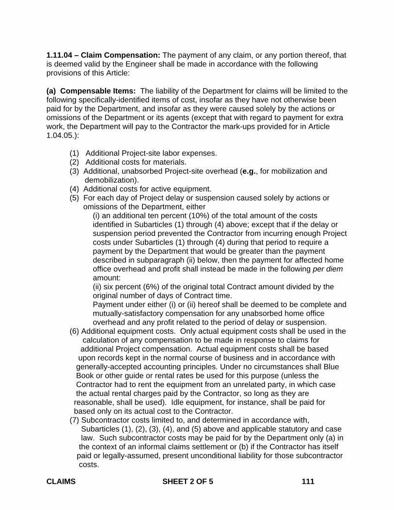
1.11.04 – Claim Compensation: The payment of any claim, or any portion thereof, that is deemed valid by the Engineer shall be made in accordance with the following provisions of this Article: (a) Compensable Items: The liability of the Department for claims will be limited to the following specifically-identified items of cost, insofar as they have not otherwise been paid for by the Department, and insofar as they were caused solely by the actions or omissions of the Department or its agents (except that with regard to payment for extra work, the Department will pay to the Contractor the mark-ups provided for in Article 1.04.05.):
(1) Additional Project-site labor expenses. (2) Additional costs for materials. (3) Additional, unabsorbed Project-site overhead (e.g., for mobilization and demobilization). (4) Additional costs for active equipment. (5) For each day of Project delay or suspension caused solely by actions or
omissions of the Department, either (i) an additional ten percent (10%) of the total amount of the costs identified in Subarticles (1) through (4) above; except that if the delay or suspension period prevented the Contractor from incurring enough Project costs under Subarticles (1) through (4) during that period to require a payment by the Department that would be greater than the payment described in subparagraph (ii) below, then the payment for affected home office overhead and profit shall instead be made in the following per diem amount: (ii) six percent (6%) of the original total Contract amount divided by the original number of days of Contract time. Payment under either (i) or (ii) hereof shall be deemed to be complete and mutually-satisfactory compensation for any unabsorbed home office overhead and any profit related to the period of delay or suspension.
(6) Additional equipment costs. Only actual equipment costs shall be used in the calculation of any compensation to be made in response to claims for additional Project compensation. Actual equipment costs shall be based upon records kept in the normal course of business and in accordance with generally-accepted accounting principles. Under no circumstances shall Blue Book or other guide or rental rates be used for this purpose (unless the Contractor had to rent the equipment from an unrelated party, in which case the actual rental charges paid by the Contractor, so long as they are reasonable, shall be used). Idle equipment, for instance, shall be paid for based only on its actual cost to the Contractor. (7) Subcontractor costs limited to, and determined in accordance with,
Subarticles (1), (2), (3), (4), and (5) above and applicable statutory and case law. Such subcontractor costs may be paid for by the Department only (a) in the context of an informal claims settlement or (b) if the Contractor has itself paid or legally-assumed, present unconditional liability for those subcontractor costs. CLAIMS SHEET 2 OF 5 111
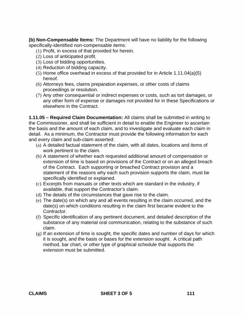
(b) Non-Compensable Items: The Department will have no liability for the following specifically-identified non-compensable items:
(1) Profit, in excess of that provided for herein. (2) Loss of anticipated profit. (3) Loss of bidding opportunities. (4) Reduction of bidding capacity. (5) Home office overhead in excess of that provided for in Article 1.11.04(a)(5)
hereof. (6) Attorneys fees, claims preparation expenses, or other costs of claims
proceedings or resolution. (7) Any other consequential or indirect expenses or costs, such as tort damages, or
any other form of expense or damages not provided for in these Specifications or elsewhere in the Contract.
1.11.05 – Required Claim Documentation: All claims shall be submitted in writing to the Commissioner, and shall be sufficient in detail to enable the Engineer to ascertain the basis and the amount of each claim, and to investigate and evaluate each claim in detail. As a minimum, the Contractor must provide the following information for each and every claim and sub-claim asserted:
(a) A detailed factual statement of the claim, with all dates, locations and items of work pertinent to the claim.
(b) A statement of whether each requested additional amount of compensation or extension of time is based on provisions of the Contract or on an alleged breach of the Contract. Each supporting or breached Contract provision and a statement of the reasons why each such provision supports the claim, must be specifically identified or explained.
(c) Excerpts from manuals or other texts which are standard in the industry, if available, that support the Contractor’s claim.
(d) The details of the circumstances that gave rise to the claim. (e) The date(s) on which any and all events resulting in the claim occurred, and the
date(s) on which conditions resulting in the claim first became evident to the Contractor.
(f) Specific identification of any pertinent document, and detailed description of the substance of any material oral communication, relating to the substance of such claim.
(g) If an extension of time is sought, the specific dates and number of days for which it is sought, and the basis or bases for the extension sought. A critical path method, bar chart, or other type of graphical schedule that supports the extension must be submitted.
CLAIMS SHEET 3 OF 5 111
(h) When submitting any claim over $50,000, the Contractor shall certify in writing, under oath and in accordance with the formalities required by the contract, as to the following:
(1) That supporting data is accurate and complete to the Contractors best knowledge and belief;
(2) That the amount of the dispute and the dispute itself accurately reflects what the Contractor in good faith believes to be the Departments liability;
(3) The certification shall be executed by: a. If the Contractor is an individual, the certification shall be
executed by that individual. b. If the Contractor is not an individual, the certification shall be
executed by a senior company official in charge at the Contractor’s plant or location involved or an officer or general partner of the Contractor having overall responsibility for the conduct of the Contractors affairs.
1.11.06 – Auditing of Claims: All claims filed against the Department shall be subject to audit by the Department or its agents at any time following the filing of such claim. The Contractor and its subcontractors and suppliers shall cooperate fully with the Department's auditors. Failure of the Contractor, its subcontractors, or its suppliers to maintain and retain sufficient records to allow the Department or its agents to fully evaluate the claim shall constitute a waiver of any portion of such claim that cannot be verified by specific, adequate, contemporaneous records, and shall bar recovery on any claim or any portion of a claim for which such verification is not produced. Without limiting the foregoing requirements, and as a minimum, the Contractor shall make available to the Department and its agents the following documents in connection with any claim that the Contractor submits:
(1) Daily time sheets and foreman's daily reports. (2) Union agreements, if any. (3) Insurance, welfare, and benefits records. (4) Payroll register. (5) Earnings records. (6) Payroll tax returns. (7) Records of property tax payments. (8) Material invoices, purchase orders, and all material and supply acquisition
contracts. (9) Materials cost distribution worksheets. (10) Equipment records (list of company equipment, rates, etc.). (11) Vendor rental agreements (12) Subcontractor invoices to the Contractor, and the Contractor's certificates of
payments to subcontractors. (13) Subcontractor payment certificates. (14) Canceled checks (payroll and vendors). (15) Job cost reports. (16) Job payroll ledger.
CLAIMS SHEET 4 OF 5 111
(17) General ledger, general journal (if used), and all subsidiary ledgers and journals, together with all supporting documentation pertinent to entries made in these ledgers and journals.
(18) Cash disbursements journals. (19) Financial statements for all years reflecting the operations on the Project. (20) Income tax returns for all years reflecting the operations on the Project. (21) Depreciation records on all company equipment, whether such records are
maintained by the company involved, its accountant, or others. (22) If a source other than depreciation records is used to develop costs for the
Contractor's internal purposes in establishing the actual cost of owning and operating equipment, all such other source documents.
(23) All documents which reflect the Contractor's actual profit and overhead during the years that the Project was being performed, and for each of the five years prior to the commencement of the Project.
(24) All documents related to the preparation of the Contractor's bid, including the final calculations on which the bid was based.
(25) All documents which relate to the claim or to any sub-claim, together with all documents that support the amount of damages as to each claim or sub-claim.
(26) Worksheets used to prepare the claim, which indicate the cost components of each item of the claim, including but not limited to the pertinent costs of labor, benefits and insurance, materials, equipment, and subcontractors’ damages, as well as all documents which establish the relevant time periods, individuals involved, and the Project hours and the rates for the individuals.
(27) The name, function, and pertinent activity of each Contractor’s or subcontractor’s official, or employee involved in or knowledgeable about events that give rise to, or facts that relate to, the claim.
(28) The amount(s) of additional compensation sought and a break-down of the amount(s) into the categories specified as payable under Article 1.11.04 above.
(29) The name, function, and pertinent activity of each Department official, employee or agent involved in or knowledgeable about events that give rise to, or facts that relate to, the claim.
CLAIMS SHEET 5 OF 5 111
January 2010
CONNECTICUT SUPPLEMENTAL SPECIFICATION
SECTION 1.20 GENERAL CLAUSES FOR FACILITIES CONSTRUCTION
1.20-1.00 – General: Delete the last sentence of the first paragraph and replace with the following: “Facilities Construction is defined as the type of construction that requires the issuance of a Certificate of Compliance (C.O.C.) by the State Building Inspector or his authorized representative at the completion of a project, and includes site work considered ancillary to this type of construction.” Add the following article: 1.20-1.01.01—Definitions: OWNER: Where used herein, it is synonymous with Department or State. 1.20-1.02.04 – Examination of Plans, Specifications, Special Provisions and Site of Work: Delete the first sentence of the first paragraph and replace with the following: “CSI-formatted specifications are organized into Divisions and Sections based on the CSI’s “MasterFormat” numbering system.” 1.20-1.02.13 – Knowledge of Applicable Laws: Delete Items 1 through 9 in their entirety and replace with the following: 1. “The 2003 International Building Code with the State Building Code, including
latest Connecticut Supplement and Amendments. 2. The 2003 International Plumbing Code. 3. The 2003 International Mechanical Code. 4. The 2003 International Existing Building Code. 5. The 2006 International Energy Conservation Code. 6. The 2005 NFPA 70 National Electrical Code. 7. The 2003 ICC/ANSI A117.1. GENERAL CLAUSES FOR FACILITIES CONSTRUCTION SHEET 1 OF 16 120
8. The Fire Safety Code, including latest Connecticut Supplement and Amendments.
9. The 2003 International Fire Code. 10. The 2003 NFPA 1 Uniform Fire Code. 11. The 2003 NFPA 101 Life Safety Code.” Add the following as the new last paragraph: “All work to be performed by the Contractor shall comply with the “Americans with Disabilities Act Accessibility Guidelines.” 1.20-1.03.01 – Consideration of Bids: Delete the entire article and replace with the following: “The apparent low bidder shall submit to the Manager of Contracts a Schedule of Values within 14 days after bid opening. Any other Contractor that the Department may subsequently designate as the apparent lowest bidder shall make the aforesaid submission within 14 days from the date on which the Department notifies said Contractor that it has become the apparent lowest bidder. If, however, the Department deems it necessary for such a subsequently designated Contractor to make said submission within a shorter period of time, the Contractor shall make the submission within the time designated by the Department.
The total in the Schedule of Values shall equal the bid dollar amount for the Major Lump Sum Item (MLSI).
The Schedule of Values shall be divided into “Line Items” listed separately for each CSI Section of the Special Provisions. An additional line item for “Mobilization” may be incorporated into the Schedule of Values; however, this item may not exceed 10% of the value of the MLSI. The “Mobilization” line item will also include costs associated with “General Conditions” and “Insurance/Bonding.” Where requested by the Department, the Contractor shall break down the line items further into more specific line items.
In the event that this Contract is terminated or a portion of this Contract is deleted for any reason or in any way allowable by law under this Contract after the apparent low bidder has been awarded the Contract, the Schedule of Values will not be used for estimating payment due the Contractor for work completed prior to such termination of the Contract or deletion of work thereunder. In the case of Contract termination, payment shall be made in accordance with Article 1.05.14.” GENERAL CLAUSES FOR FACILITIES CONSTRUCTION SHEET 2 OF 16 120

1.20-1.05.02--Shop Drawings, Product Data, Product Samples and Quality Assurance Submittals Delete the last sentence of the first paragraph and replace with the following: “All facsimiles or other electronic documents from the Contractor shall be followed by an official transmittal.” Delete the third paragraph and replace with the following: “The Contractor shall number each submittal consecutively: When resubmitting a “Revise and Resubmit” or “Rejected” submittal, the Contractor shall label the transmittal with the original submittal number followed by a letter to designate the additional submission. All submittals shall be numbered conforming to the following examples:” In column B of line 001, line 001a, and line 001b of the table in subsection 1, replace “07511” with “075110.” Add the following to the end of the first paragraph of subsection 2: “The Department reserves the right to return partial submittals unreviewed to the Contractor.” Revise the third paragraph of subsection 2 to read: “The Contractor shall allow at least 60 calendar days for review of any submittal requiring approval by FAA, FTA, any railroad, DEP, U.S. Coast Guard, Army Corps of Engineers, or any other outside agency.” Delete the third and fourth paragraphs of subsection 3 and replace with the following: “The Designer will not review submittals and the Engineer will not process payment estimates until the initial submittal schedule has been provided. Any delays in construction due to the Contractor's failure to provide a submittal schedule shall be the responsibility of the Contractor. The Contractor must update its submittal schedule at least once a month, and distribute and post each updated schedule in the manner described above. The Engineer reserves the right not to process payment estimates without a recently updated submittal schedule on file.” Replace the first sentence of the first paragraph of subsection 4 with the following: GENERAL CLAUSES FOR FACILITIES CONSTRUCTION SHEET 3 OF 16 120

“Shop Drawings consist of fabrication and installation drawings, roughing-in and setting drawings, schedules, patterns, templates and similar drawings, and wiring diagrams showing field-installed wiring, including power, signal, and control wiring.” Replace the second paragraph of subsection 4 with the following: “Shop drawings shall include the following information: Contract number, Project description, number and title of the drawing, date of drawing, revision number, name of Contractor and subcontractor submitting drawings, dimensions, identification of products, shopwork manufacturing instructions, design calculations, statement of compliance with Contractual standards, notation of dimensions established by field measurement, relationship to adjoining construction clearly indicated, seal and signature of a professional engineer if specified, and any other information required by individual Contract provisions.” Replace the first sentence of the first paragraph of subsection 5 with the following: “Product data consist of printed information such as manufacturer’s product specifications, manufacturer’s installation instructions, manufacturer’s catalog cuts, standard color charts, wiring diagrams showing factory-installed wiring, printed performance curves, operational range diagrams, and mill reports.” Replace the first sentence of the first paragraph of subsection 7 with the following: “Quality assurance submittals consist of qualification data, design data, certifications, manufacturer’s instructions, manufacturer’s field reports, test reports, Material Safety Data Sheets (MSDSs), and other quality assurance information required by individual Contract provisions.” 1.20-1.05.04—Coordination of Special Provisions, Plans, Supplemental Specifications and Standard Specifications and Other Contract Requirements: Delete the first and second paragraphs and replace with the following: “Industry Standards: Each entity engaged in construction of the Contract shall be familiar with industry standards applicable to that entity's construction activities. If printed standards have been established by organizations referenced in Article 1.01.02 or in the Contract, the Contractor shall obtain copies of said standards directly from the publication source. Unless the Special Provisions include more stringent requirements, applicable construction industry standards have the same force and effect as if bound or copied directly into the Special Provisions to the extent referenced. Such standards are made a part of the Contract by reference.” GENERAL CLAUSES FOR FACILITIES CONSTRUCTION SHEET 4 OF 16 120
Add the following article: 1.20-1.05.08—Schedules and Reports: Daily Construction Reports: The Contractor shall assist the Engineer in the preparation of a daily construction report, by ensuring that each of the Contractor’s employees and subcontractors working on the Project site on a given day signs the Engineer’s sign-in sheet for that day; and by keeping and providing to the Engineer its own daily list of employees and subcontractors who worked on the Project site on that day. Add the following article: 1.20-1.05.23—Requests for Information (RFIs): The Contractor shall forward all RFIs to the Engineer in writing (facsimile or other electronic document) for review. The Engineer will forward the RFI to the Designer for review. Upon receipt of an RFI, the Designer will attempt to determine if additional information is required from the Contractor to respond to the RFI, and request said information from the Engineer. All other RFIs will be responded to within 10 calendar days of receipt by the Designer. 1.20-1.05.24--Project Meetings: Delete the third paragraph under subsection 1. Delete the second paragraph under subsection 2 and replace with the following: “The meeting participants shall review progress of other construction activities and preparations for the particular activity under consideration, including requirements of Contract documents, related requests for interpretations, related construction orders, purchases, deliveries, submittals, review of mockups, possible conflicts, compatibility problems, time schedules, weather limitations, manufacturer’s written recommendations, warranty requirements, compatibility of materials, acceptability of substrates, temporary facilities and controls, space and access limitations, regulations of authorities having jurisdiction, testing and inspecting requirements, installation procedures coordination with other work, required performance results, protection of adjacent work, and protection of construction and personnel.” Delete the second, third and fourth paragraph under subsection 3 and replace with the following: “The Contractor shall provide the Engineer with a detailed agenda for the proposed GENERAL CLAUSES FOR FACILITIES CONSTRUCTION SHEET 5 OF 16 120
meeting, specifying what topics will be covered. In addition to representatives of the Engineer, each subcontractor, supplier or other entity concerned with current progress or involved in planning, coordination or performance of future activities shall attend these meetings. All participants at the meeting shall be familiar with the Project and authorized to conclude matters relating to the Project. At each progress meeting, the participants shall (1) review items of significance that could affect progress; (2) discuss topics appropriate to the current status of the Project; (3) review progress since the last meeting; (4) determine whether each activity is on time, ahead of schedule, or behind schedule, in relation to the Contractor's Construction Schedule; (5) determine how to expedite any Project work that may be behind schedule; (6) discuss whether or not schedule revisions are required to ensure that current and subsequent activities will be completed within the Contract time; and (7) review the present and future needs of each entity represented at the meeting, including such items as interface requirements, time, sequences, deliveries, off-site fabrication problems, access, site utilization, temporary facilities and controls, hours of work, hazards and risks, housekeeping, quality and work standards, status of correction of deficient items, field observations, requests for interpretations, status of proposal requests, pending changes, status of construction orders, and documentation of information for payment requests. The Engineer will distribute copies of minutes of the meeting to the Designer and the Contractor. The Contractor shall distribute copies to parties who were or should have been at the meeting.” Delete article 1.20-1.05.25—Schedules and Reports in its entirety 1.20-1.06.08 - Warranties: Delete the eighth and ninth paragraph and replace with the following: “The Contractor shall: (a) Bind warranties in heavy-duty, commercial-quality, durable 3-ring vinyl-covered loose-leaf binders, thick enough to accommodate the contents, and sized to receive 8 1/2-inch x 11-inch paper (216-millimeter x 279-millimeter) paper. (b) Identify the binder’s contents on the binder’s front and spine with the typed or printed title “WARRANTIES,” the Project title or name, and the name of the Contractor. (c) Provide a heavy paper divider with a tab for each separate warranty. (d) Mark the tab to identify the related product or installation. (e) Provide a typed description of the product or installation, including the name of the product, and the name, address and telephone number of the Contractor or pertinent subcontractor. (f) Furnish to the Department a written warranty for all Project work accompanied by a cover letter with the following contents: [Addressed to:] GENERAL CLAUSES FOR FACILITIES CONSTRUCTION SHEET 6 OF 16 120

Commissioner of Transportation Department of Transportation P.O. Box 317546 Newington, Connecticut 06131-7546 Project Title and Number [We] hereby warrant all materials and workmanship for all work performed under this Contract for a period of one (1) year from [date of issuance of C.O.C.] against failures of workmanship and materials in accordance with the Contract. Furthermore, as a condition of this warranty, [we] agree to have in place all insurance coverage identified in the Contract for the performance of any warranty work. [Signature:] [Name of authorized signatory] [Title] (g) Submit to the Engineer, upon completion of installation of materials or assemblies that are required to have either a flame-rating or a fire-endurance hourly rating, a detailed letter certifying that the required rating has been attained. Upon determination by the Engineer that Project work covered by a warranty has failed, the Contractor shall replace or rebuild the work to an acceptable condition complying with Contract requirements. The Contractor is responsible for the cost of replacing or rebuilding defective construction or components and those which may have needed to be damaged or removed in order to cure the defective work including costs of material, equipment, labor, and material disposal, regardless of whether or not the State has benefited from use of the work through a portion of its anticipated useful service life. The Contractor shall respond to the Project Site when Project work covered by a warranty has failed within 3 calendar days, unless in the Engineer’s opinion said failure is deemed to be an emergency, in which case the Contractor shall respond to the Project Site as directed by the Engineer.” 1.20-1.08.03—Prosecution of Work: Under subsection ‘3. Cutting and Patching,’ delete the heading ‘B. Protection of Structural Elements’ and replace with the following: “B. Protection:” Move the existing first and second paragraphs to under the following subparagraph: “1. Structural Elements:” GENERAL CLAUSES FOR FACILITIES CONSTRUCTION SHEET 7 OF 16 120
Add the following after the first paragraph under B: “2. Operational Elements: The Contractor shall not cut and patch operating elements and related components in a manner that results in their reducing their capacity to perform as intended or that results in increased maintenance or decreased operational life or safety. 3. Miscellaneous Elements: The Contractor shall not cut and patch miscellaneous elements or related components in a manner that could change their load-carrying capacity, that results reducing their capacity to perform as intended, or that results in increased maintenance or decreased operational life or safety.” Add the following after subsection 3: “4. Selective Demolition: A. Definitions: Remove: The Contractor shall detach materials from existing construction and legally dispose or recycle them off-site, unless indicated to be removed and salvaged or removed and reinstalled. Except for materials indicated to be reused, salvaged, reinstalled, or otherwise indicated to remain Engineer's property, demolished materials shall become Contractor's property and shall be removed from the Project Site. Remove and Salvage: The Contractor shall detach materials from existing construction and deliver them to Engineer. The Engineer reserves the right to identify other materials for salvage during the course of demolition. Remove and Reinstall: The Contractor shall detach materials from existing construction, prepare them for reuse, and reinstall them where indicated. Existing to Remain: Existing materials of construction that are not to be removed and that are not otherwise indicated to be removed, removed and salvaged, or removed and reinstalled. B. Approval Process: The Contractor shall submit pre-demolition photographs to the Engineer prior to the commencement of Project work to show existing conditions of adjoining construction and site improvements, including finish surfaces, that might be misconstrued as damage caused by selective demolition operations. GENERAL CLAUSES FOR FACILITIES CONSTRUCTION SHEET 8 OF 16 120
Well in advance of performing any selective demolition on the Project, the Contractor shall submit to the Engineer a proposal describing the procedures that the Contractor intends to use for same. The Contractor shall include the following information, as applicable, in its proposal: (1) detailed sequence of selective demolition and removal work with starting and ending dates for each activity while ensuring that the Engineer's on-site operations are not disrupted; (2) interruption of utility services; (3) coordination for shutoff, capping, and continuation of utility services; (4) use of elevators and stairs; (5) locations of temporary partitions and means of egress; (6) coordination of Engineer's continuing occupancy of portions of existing building and of Engineer's partial occupancy of completed Project work; and (7) means of protection for items to remain and items in path of waste removal from building. The Contractor shall comply with (1) governing EPA notification regulations before beginning selective demolition; (2) hauling and disposal regulations of authorities having jurisdiction; (3) ANSI A10.6; and (4) NFPA 241. The Engineer will conduct a Pre-Demolition Meeting at the Project site in accordance with Article 1.20-1.05.24. Said meeting will review the methods and procedures related to selective demolition including, but not limited to, the following: (1) an inspection and discussion of the condition of construction to be selectively demolished; (2) a review of the structural load limitations of the existing structure; (3) a review and finalization of the selective demolition schedule and a verification of the availability of materials, demolition personnel, equipment, and facilities needed to make progress and avoid delays; (4) a review of requirements of Project work performed by other trades that rely on substrates exposed by selective demolition operations; and (5) a review of areas where existing construction is to remain and requires protection. C. Repair Materials: The Contractor shall comply with Article 1.20-1.08.03 subsection 3E for repair materials and shall comply with material and installation requirements specified in other Contract provisions. D. Examination: The Contractor shall (1) verify that utilities have been disconnected and capped; (2) survey existing conditions and correlate with requirements indicated to determine extent of selective demolition required; (3) inventory and record the condition of items to be removed and reinstalled and items to be removed and salvaged; (4) investigate and measure the nature and extent of unanticipated mechanical, electrical, or structural elements that conflict with intended function or design and submit a written report to GENERAL CLAUSES FOR FACILITIES CONSTRUCTION SHEET 9 OF 16 120
Engineer; and (5) perform surveys as the Project work progresses to detect hazards resulting from selective demolition activities. E. Utility Services: The Contractor shall (1) maintain existing utility services indicated to remain and protect them against damage during selective demolition operations; (2) not interrupt existing utilities serving occupied or operating facilities unless authorized in writing by the Engineer; (3) provide temporary services during interruptions to existing utilities, as acceptable to Engineer; (4) provide at least 3 calendar days notice to the Engineer if shutdown of service is required during changeover; and (5) locate, identify, disconnect, and seal or cap off indicated utilities serving areas to be selectively demolished. The Contractor shall arrange to shut off indicated utilities with utility companies. If utility services are required to be removed, relocated, or abandoned, before proceeding with selective demolition the Contractor shall provide temporary utilities that bypass area of selective demolition and that maintain continuity of service to other parts of building. The Contractor shall cut off pipe or conduit in walls or partitions to be removed and shall cap, valve, or plug and seal remaining portion of pipe or conduit after bypassing. The Contractor shall refer to other Contract provisions for shutting off, disconnecting, removing, and sealing or capping utilities. The Contractor shall not start selective demolition work until utility disconnecting and sealing have been completed and verified by the Engineer in writing. F. Preparation: The Contractor shall conduct selective demolition and debris-removal operations to ensure minimum interference with adjacent occupied and used facilities on the Project site. The Contractor shall not disrupt the Owner’s operations without the Engineer’s permission. The Contractor shall protect existing site improvements, appurtenances, and landscaping to remain. The Contractor shall provide temporary barricades and other protection required to prevent injury to people and damage to adjacent buildings and facilities to remain. The Contractor shall provide temporary weather protection, during interval between selective demolition of existing construction on exterior surfaces and new construction, to prevent water leakage and damage to structure and interior areas. The Contractor shall protect walls, ceilings, floors, and other existing finish work that are to remain or that are exposed during selective demolition operations. The Contractor shall cover and protect furniture, furnishings, and equipment that have not been removed. The Contractor shall provide temporary enclosures for protection of existing building GENERAL CLAUSES FOR FACILITIES CONSTRUCTION SHEET 10 OF 16 120
and construction, in progress and completed, from exposure, foul weather, other construction operations, and similar activities. The Contractor shall provide temporary weathertight enclosure for building exterior. Where heating is needed and permanent enclosure is not complete, the Contractor shall provide insulated temporary enclosures and shall coordinate enclosure with ventilating and material drying or curing requirements to avoid dangerous conditions and effects. The Contractor shall erect and maintain dustproof partitions and temporary enclosures to limit dust and dirt migration and to separate areas from fumes and noise. The Contractor shall provide and maintain interior and exterior shoring, bracing, or structural support to preserve stability and prevent movement, settlement, or collapse of construction to remain, and to prevent unexpected or uncontrolled movement or collapse of construction being demolished. The Contractor shall strengthen or add new supports when required during progress of selective demolition. G. Pollution Controls: The Contractor shall comply with governing regulations pertaining to environmental protection. The Contractor shall not use water when it may create a hazardous or objectionable condition such as ice, flooding, or pollution. The Contractor shall remove and transport debris in a manner that will prevent spillage on adjacent surfaces and areas. The Contractor shall remove debris from elevated portions of building by chute, hoist, or other device that will convey debris to grade level in a controlled descent. The Contractor shall clean adjacent structures and improvements of dust, dirt, and debris caused by selective demolition operations. The Contractor shall return adjacent areas to condition existing before selective demolition operations began. H. Performance: The Contractor shall not use explosives for demolition purposes. The Contractor shall demolish and remove existing construction only to the extent required by new construction and as indicated. The Contractor shall (1) proceed with selective demolition systematically; (2) neatly cut openings and holes plumb, square, and true to dimensions required; (3) use cutting methods least likely to damage remaining or adjoining construction; (4) use hand tools or small power tools designed for sawing or grinding, not hammering and chopping, to minimize disturbance of adjacent surfaces; (5) temporarily cover openings to remain; (6) cut or drill from the GENERAL CLAUSES FOR FACILITIES CONSTRUCTION SHEET 11 OF 16 120
exposed or finished side into concealed surfaces to avoid marring existing finished surfaces; (7) not use cutting torches until work area is cleared of flammable materials; (8) verify condition and contents of concealed spaces such as duct and pipe interiors before starting flame-cutting operations; (9) maintain fire watch and portable fire-suppression devices during flame-cutting operations; (10) maintain adequate ventilation when using cutting torches; (11) remove decayed, vermin-infested, or otherwise dangerous or unsuitable materials and promptly dispose of off-site; (12) remove structural framing members and lower to ground by method suitable to avoid free fall and to prevent ground impact or dust generation; (13) locate selective demolition equipment and remove debris and materials so as not to impose excessive loads on supporting walls, floors, or framing; and (14) dispose of demolished items and materials promptly. The Contractor shall comply with the Engineer's requirements for using and protecting walkways, building entries, and other building facilities during selective demolition operations. The Contractor shall demolish and remove foundations and other below grade structures completely unless otherwise indicated on the plans. The Contractor shall fill below grade areas and voids resulting from demolition of structures with granular fill materials. Prior to placement of fill materials, the Contractor shall ensure that the areas to be filled are free of standing water, frost, frozen material, trash, and debris. After fill placement and compaction, grade surface to meet adjacent contours and provide flow to surface drainage structures. Backfilling and grading related to demolition is included in the Major Lump Sum Item (MLSI) for the Project. There will be no separate payment for this backfilling and grading. The Contractor shall (1) demolish concrete in sections; (2) cut concrete at junctures with construction to remain to the depth shown on the Contract plans and at regular intervals using power-driven saw; and (3) remove concrete between saw cuts. The Contractor shall (1) demolish masonry in small sections; (2) cut masonry at junctures with construction to remain using power-driven saw; and (3) remove masonry between saw cuts. The Contractor shall (1) saw-cut perimeter of concrete slabs-on-grade to be demolished as shown on the Contract plans; and (2) break up and remove concrete slabs-on-grade. The Contractor shall (1) remove floor coverings and adhesive according to recommendations in RFCI-WP and its Addendum; and (2) remove residual adhesive and prepare substrate for new floor coverings by one of the methods recommended by RFCI. The Contractor shall (1) only remove existing roofing in one day to the extent that it can GENERAL CLAUSES FOR FACILITIES CONSTRUCTION SHEET 12 OF 16 120
be covered by new roofing; and (2) refer to other Contract provisions for new roofing requirements. The Contractor shall remove air conditioning equipment without releasing refrigerants. I. Reuse of Building Elements: The Contractor shall not demolish building elements beyond what is indicated on the plans without the Engineer’s approval. J. Removed and Salvaged Materials: Unless otherwise directed by the Engineer, the Contractor shall (1) store materials in a secure area until delivery to the owner; (2) transport materials to the owner’s storage area off-site; and (3) protect materials from damage during transport and storage. K. Removed and Reinstalled Materials: Unless otherwise directed by the Engineer, the Contractor shall (1) clean and repair materials to functional condition adequate for intended reuse; (2) paint equipment to match the color of new equipment; (3) protect materials from damage during transport and storage; and (4) reinstall items in locations indicated complying with installation requirements for new materials and equipment and providing connections, supports, and miscellaneous materials necessary to make item functional for use indicated. L. Existing Materials to Remain: The Contractor shall protect construction indicated to remain against damage and soiling during selective demolition. The Contractor shall drain piping and cap or plug piping with the same or a compatible piping material for piping to be abandoned in place. The Contractor shall cap or plug ducts with the same or a compatible ductwork material for ducts to be abandoned in place. The Contractor shall cut and remove concealed conduits and wiring to be abandoned in place 2-inches (50-mm) below the surface of the adjacent construction, cap the conduit end, and patch the surface to match the existing finish. The Contractor shall cut existing conduits installed in concrete slabs to be abandoned in place flush with the top of the slab and fill conduit end with a minimum of 4-inches (100-mm) of concrete. M. Patching and Repairing: The Contractor shall comply with Article 1.20-1.08.03 subsection 3H for patching and GENERAL CLAUSES FOR FACILITIES CONSTRUCTION SHEET 13 OF 16 120
repairing damage to adjacent construction caused by selective demolition operations. N. Disposal of Demolished Materials: The Contractor shall (1) not allow demolished materials to accumulate or be sold on the Project Site; (2) not burn demolished materials on the Project Site; and (3) promptly and legally dispose or recycle demolished materials off the Project Site.” 1.20-1.08.05--Personnel and Equipment: Replace “FM with “FMG” in subsection (a) Add the following article: “1.20-1.08.12--Semi-Final and Final Inspections: 1. Semi-Final Inspection: Before requesting the Semi-Final Inspection, the Contractor shall show 100% completion for all Project work claimed as complete. The Contractor shall submit final test/adjust/balance records including the final air and water balance report. For all incomplete Project work, the Contractor shall prepare its own “Punch List” of the incomplete items and reasons the work is not complete. The Contractor shall submit final test/adjust/balance records including the final air and water balance report. On receipt of a Contractor request for inspection, the Engineer will proceed with inspection or notify the Contractor of unfulfilled requirements. The Engineer will prepare a “Punch List” of unfilled, substandard, or incomplete items. During this inspection, the Contractor shall have all technicians necessary to demonstrate the complete operation of all systems on-site. Examples of such systems include, but are not limited to, the following: boiler, HVAC, fire alarm, and building automation. The Engineer will advise the Contractor of the construction that must be completed or corrected before the issuance of the C.O.C. Results of the completed inspection will form the basis of requirements for the Final Inspection. The Engineer reserves the right to issue the C.O.C. after the Semi-Final Inspection if there are no Building Code or Fire Code compliance issues or any major “Punch List” items. 2. Final Inspection: Before requesting Final Inspection for issuance of the C.O.C., the Contractor shall: (1) submit specific warranties, maintenance service agreements, final certifications and similar documents; (2) submit Record Drawings, Record Specifications, operations and maintenance manuals, final project photographs, property surveys, and similar final record information; (3) deliver spare parts; (4) make final changeover of permanent locks and deliver the keys to the Engineer; (5) complete start-up testing of systems; (6) train the owner's operation and maintenance personnel; (7) discontinue or change over and remove temporary facilities from the Project Site, along with construction tools, mock-ups, and similar elements; (8) complete final GENERAL CLAUSES FOR FACILITIES CONSTRUCTION SHEET 14 OF 16 120

cleaning requirements, including touch-up painting; (9) touch-up and otherwise repair and restore marred exposed finishes to eliminate visual defects; (10) submit a certified copy of the Engineer's “Punch List” of items to be completed or corrected, stating that each item has been completed or otherwise resolved for acceptance, and the list has been endorsed and dated by the Engineer; (11) submit final meter readings for utilities, a measured record of stored fuel, and similar data as of the date of Final Inspection, or when the Engineer took possession of and responsibility for corresponding elements of the Project work; and (12) install permanent electrical service. The Contractor shall install permanent electrical service prior to Semi-Final Inspection if requested by the Engineer, or if necessary for the Engineer or Contractor to perform testing of building and other related systems and equipment to certify acceptance and completion of Project work. The Contractor shall submit all outstanding items or unacceptable submissions from the Semi-Final Inspection, or other outstanding items required for submittal, prior to the Final Inspection. On receipt of a Contractor request for inspection, the Engineer will proceed with inspection and notify the Contractor of unfulfilled requirements.” 1.20 – 1.08.13 – Termination of the Contractor’s Responsibility: Add subsection 3 as follows: “3. Insurance Coverage: The Contractor shall have in place all insurance coverage identified in Article 1.03.07 for the performance of any warranty work.” 1.20-1.08.14--Acceptance of Project: Add the following to subsection 2 under the heading “Equipment and Systems Maintenance Manual:” “(j) Copies of maintenance agreements with service agent name and telephone number.” Add the following paragraph in subsection 3 after the second paragraph: “The Contractor shall provide a syllabus prior to the training to ensure that the appropriate owner’s operation and maintenance personnel are in attendance.” Delete the last paragraph and replace with the following: The Contractor shall submit to the Engineer for approval, a qualified commercial videographer to videotape the training sessions. The videographer shall be a firm or an individual of established reputation that has been regularly engaged as a professional videographer for not less than 3 years. GENERAL CLAUSES FOR FACILITIES CONSTRUCTION SHEET 15 OF 16 120
The Contractor shall video record each training session and provide said video in DVD format to the Engineer for the owner’s future use.” Add the following section: “1.20-1.09.06—Partial Payments: With each payment request under the MLSI, the Contractor shall submit AIA Form G702 (Application and Certificate of Payment) and Form G703 (Continuation Sheet). The Contractor is not required to obtain the Architect’s signature on Form G702. Once approved by the Engineer, the Forms G702 and G703 become the basis of payment under the MLSI.” Add the following section: “1.20-9.75.04—Method of Measurement: Mobilization as defined in Article 1.20-1.03.01 will be paid in the manner described hereinafter; however, the determination of the total contract price earned shall not include the amount of mobilization earned during the period covered by the current monthly estimate – but shall include amounts previously earned and certified for payment: 1. When the first payment estimate is made, 25 percent of the “Mobilization” line item will be certified for payment. 2. When the Baseline Schedule, as specified under Section 1.05.08, is accepted, 50 percent of the “Mobilization” line item, minus any previous payments, will be certified for payment. 3. When 10 percent of the total original contract price is earned and the Baseline Schedule, as specified under Section 1.05.08, is accepted, 75 percent of the “Mobilization” line item, minus any previous payments, will be certified for payment. 4. When 30 percent of the total original contract price is earned and the Baseline Schedule, as specified under Section 1.05.08, is accepted, 100 percent of the “Mobilization” line item, minus any previous payments, will be certified for payment.” GENERAL CLAUSES FOR FACILITIES CONSTRUCTION SHEET 16 OF 16 120

January 2010
CONNECTICUT SUPPLEMENTAL SPECIFICATION
SECTION 2.02 ROADWAY EXCAVATION, FORMATION OF
EMBANKMENT AND DISPOSAL OF SURPLUS MATERIAL
2.02.04 – Method of Measurement: Second to last Paragraph - replace the last sentence with the following: “Bituminous parking areas are considered as bituminous concrete pavement.”
ROADWAY EXCAVATION, FORMATION OF EMBANKMENT AND DISPOSAL OF SURPLUS MATERIAL SHEET 1 OF 1 202
January 2010
CONNECTICUT SUPPLEMENTAL SPECIFICATION
SECTION 2.05 TRENCH EXCAVATION
Delete the entire Section and replace with the following: 2.05.01--Description: Paragraph 2 - Delete the only sentence and replace with the following: 2) The removal of stormwater drainage structures, stormwater pipes and appurtenances beyond the limits of the roadway and structure excavation. Sub article 2 - Rock in Trench - Delete the only sentence and replace with the following: (2) Rock, insofar as it applies to trench excavation, shall be defined as rock in definite ledge formation, boulders, or portions of boulders, cement masonry structures, concrete structures, reinforced concrete pipe, Portland cement concrete pavement or base, of 1/2 cubic yard (0.5 cubic meters) or more in volume, removed as indicated or directed from within the payment lines for trench excavation. 2.05.05 -Basis of Payment Paragraph 13 - Delete the entire sentence “There will be no direct payment for the plugging of existing pipes....." and replace with the following: There will be no direct Payment for the plugging of existing pipes, removal and disposal of metal or plastic pipes or for the breaking up of floors in drainage structures being abandoned. The cost shall be included in the contract unit prices of the drainage and excavation items.
TRENCH EXCAVATION SHEET 1 OF 1 205
July 2005
CONNECTICUT SUPPLEMENTAL SPECIFICATION
SECTION 3.04 PROCESSED AGGREGATE BASE
Delete the entire Section and replace with the following: 3.04.01--Description: The base shall consist of a foundation constructed on the prepared subbase or subgrade in accordance with these specifications and in conformity with the lines, grades, compacted thickness and typical cross-section as shown on the plans. 3.04.02--Materials: All materials for this work shall conform to the requirements of Article M.05.01. 3.04.03--Construction Methods: Only one type of coarse aggregate shall be used on a project unless otherwise permitted by the Engineer.
Prior to placing the processed aggregate base, the prepared subbase or subgrade shall be maintained true to line and grade, for a minimum distance of 200 feet (60 meters) in advance of the work. None of the aggregate courses shall be placed more than 500 feet (150 meters) ahead of the compaction and binding operation on that particular course.
The processed aggregate base shall be spread uniformly by a method approved by the Engineer. The thickness of each course shall not be more than 4 inches (100 millimeters) after compaction, unless otherwise ordered.
After the aggregate is spread, it shall be thoroughly compacted and bound by use of equipment specifically manufactured for that purpose. Rollers shall deliver a ground pressure of not less than 300 pounds per lineal inch (52.5 newtons/millimeter) of contact width and shall have a weight (mass) not less than 10 tons (9100 kilograms). Vibratory units shall have a static weight (mass) of not less than 4 tons (3650 kilograms). Water may be used during the compaction and binding operation and shall be applied from an approved watering device. The compacting and binding operation shall begin at the outside edges, overlapping the shoulders for a distance of not less than 6 inches (150 millimeters) and progress towards the middle, parallel with the centerline of the pavement. The work shall cover the entire surface of the course with uniform overlapping of each preceding track or pass. Areas of super-elevation and special cross slope shall be compacted by beginning at the lowest edge and proceeding towards the higher edge, unless otherwise directed by the Engineer. The compacting and binding operation shall be continued until the voids in the aggregates have been reduced to provide a firm and uniform surface satisfactory to the Engineer. The amount of compactive effort shall in no case shall be less than four (4) complete passes of the compacting and binding operations. All aggregate shall be completely compacted and bound at the end of each day’s work or when traffic is to be permitted to operate on the
PROCESSED AGGREGATE BASE SHEET 1 OF 2 304
road. The dry density of each layer of processed aggregate base after compaction shall not be less than 95 percent of the dry density for that material when tested in accordance with AASHTO T180, Method D.
Should the subbase or subgrade material become churned up or mixed with the
processed aggregate base at any time, the Contractor shall, without additional compensation remove the mixture. The Contractor shall add new subbase material, if required, and reshape and recompact the subbase in accordance with the requirements of Article 2.12.03. New aggregate material shall be added, compacted and bound, as hereinbefore specified, to match the surrounding surface.
Any surface irregularities which develop during, or after work on each course, shall be corrected by loosening material already in place and removing or adding aggregate as required. The entire area, including the surrounding surface, shall be re-compacted and rebound until it is brought to a firm and uniform surface satisfactory to the Engineer.
3.04.04--Method of Measurement: Processed Aggregate Base will be measured horizontally in place after final grading and compaction. Materials placed beyond the horizontal limits indicated on the plans will not be measured for payment.
The total thickness shall be as indicated on the plans, or as ordered by the Engineer and within a tolerance of minus three-fourths of an inch (-3/4”) to plus one-half inch (+ 1/2”) (-19 millimeters to +13 millimeters).
Measurements to determine the thickness will be taken by the Engineer at
intervals of 500 feet (150 meters) or less, along lanes, and shall be considered representative of the lane. For the purpose of these measurements, a shoulder will be considered a lane.
If a thickness measurement is taken and found deficient, the Engineer will take
such additional measurements as he considers necessary to determine the longitudinal limits of the deficiency. Areas not within allowable tolerances shall be corrected, as ordered by the Engineer, without additional compensation to the Contractor. 3.04.05--Basis of Payment: This work will be paid for at the contract unit price per cubic yard for “Processed Aggregate Base”, complete in place, which price shall include all materials, tools, equipment and work incidental thereto. Pay Item Pay Unit Processed Aggregate Base c.y. (cu. m)
PROCESSED AGGREGATE BASE SHEET 2 OF 2 304
July 2006
CONNECTICUT SUPPLEMENTAL SPECIFICATION
SECTION 4.01 CONCRETE PAVEMENT
Article 4.01.03-A. Composition: Add the following new paragraph before the last paragraph: “The temperature of the concrete at the time of placement shall not be less than 60˚ F (15.5˚ C) or greater than 90˚ F (32˚ C). For pumped concrete, the temperature shall be determined at the placement end of the pump line. The temperature of the concrete shall be determined in accordance with ASTM C1064.”
CONCRETE PAVEMENT SHEET 1 OF 1 401
January 2009
CONNECTICUT SUPPLEMENTAL SPECIFICATION
SECTION 5.14 PRESTRESSED CONCRETE MEMBERS
Article 5.14.03 – Construction Methods: Change the last sentence of 5.14.03-16 – Methods and Equipment to read: “The results of this investigation, including computations, shall be submitted to the Engineer.”
PRESTRESSED CONCRETE MEMBERS SHEET 1 OF 1 514
July 2010
CONNECTICUT SUPPLEMENTAL SPECIFICATION
SECTION 6.01 CONCRETE FOR STRUCTURES
Article 6.01.02 – Materials: Add the following: Material for stay-in-place metal forms shall be made of zinc-coated (galvanized) steel sheet conforming to ASTM Specification A653, Structural Steel (SS) Grade 33 through 80 (ASTM Specification A653M, Structural Steel (SS) Grade 250 through 550). The minimum gage thickness shall be 20 gage. Coating weight shall conform to ASTM A924, Class G235 (ASTM A924M, Class Z700) and shall otherwise meet all requirements relevant to steel stay-in-place metal forms and the placing of concrete as specified herein and as noted on the contract drawings. Material for the form supports shall be fabricated from the same material and conform to the same material requirements as the forms themselves or they shall be fabricated from structural steel conforming to the requirements of ASTM A36 (ASTM A36M) which shall be hot-dip galvanized in accordance with ASTM A123 (ASTM A123M). Lightweight filler material shall be as recommended by the form’s manufacturer. Subarticle 6.01.03 – 3, Forms: Add the following: Stay-in-Place Metal Form System: Stay-in-place metal forms shall have a minimum depth of form valley equal to two inches (50 millimeters). The forms shall have closed tapered ends. Lightweight filler material shall be used in the form valleys. The metal forms shall be designed on the basis of dead load of the form, reinforcement and the plastic concrete, including the additional weight of concrete due to the deflection of the metal forms, plus 50 pounds per square foot (2.40 kilopascals) for construction loads. The allowable stress in the corrugated form and the accessories shall not be greater than 0.725 times the yield strength of the furnished material and the allowable stress shall not exceed 36,000 psi (250 megapascal). The span for design and deflection shall be the clear distance between edges of the beams or girders less two inches (50 millimeters) and shall be measured parallel to the form flutes. Maximum deflection of the forms under the weight of the plastic concrete, reinforcement, and forms shall not exceed 1/180 of the form span or 0.5 inches (13 millimeters), whichever is less. The permissible form camber shall be based on the actual dead load condition. Camber shall not be used to compensate for deflection in excess of the foregoing limits. CONCRETE FOR STRUCTURES SHEET 1 OF 4 601
Form support angles shall be designed as a cantilever. The horizontal leg of the form’s support angle shall not be greater than 3 inches (75 millimeters). Before fabricating any material, the Contractor shall submit working drawings to the Engineer for review in accordance with Article 1.05.02-2, Working Drawings. These drawings shall include the proposed method of form construction, erection plans including weld procedure(s), material lists, material designation, gage of all materials, and the details of corrugation. Also, copies of the form design computations shall be submitted with the working drawings. Form supports shall be used and no stay-in-place metal forms shall be placed over or be directly supported by the top flanges of beams or girders. The form supports may be supported by or be attached to the top flanges. Stay-in-place metal forms shall not be used in bays where longitudinal slab construction joints are located. Stay-in-place metal forms shall not be used under cantilevered slabs such as the overhang outside of fascia members. Welding to the top flanges of steel beams and girders is not allowed in the areas where the top flanges are in tension, or as indicated on the plans. Alternate installation procedures shall be submitted addressing this condition. Drilling of holes in prestressed concrete beams or the use of power-actuated tools on the prestressed concrete beams for fastening of the form supports to the prestressed concrete beams will not be permitted. No welding will be permitted on the reinforcing steel in the prestressed units. All edges of openings cut for drains, pipes, and similar appurtenances shall be independently supported around the entire periphery of the opening. All fabricated stay-in-place metal forms shall be unloaded, stored, and handled in such a manner as to preclude damage to the forms. Damaged material shall be replaced at no additional cost. Any exposed form or form support metal where the galvanized coating has been damaged, shall be thoroughly cleaned, wire brushed, then coated with two coats of a zinc dust-zinc oxide primer, FS No. TT-P-641d, Type II, as directed by the Engineer. All fabricated stay-in-place metal forms shall be stored at the project site at least four inches (100 millimeters) above the ground on platforms, skids or other suitable supports and shall be protected against corrosion and damage. Forms shall be installed from the topside in accordance with the manufacturer’s placing plans, recommended details, and printed instructions. Forms shall be constructed to the lines, grades, shapes, and dimensions shown on the plans, unless otherwise directed by the Engineer. Form supports shall ensure that forms retain their correct dimensions and positions during use at all times. Form supports shall provide vertical adjustment to maintain design slab thickness at the crest of corrugation, to compensate for variations in camber of beams and girders, and to allow for deflections. CONCRETE FOR STRUCTURES SHEET 2 OF 4 601
Field cutting of form sheet metal shall be made by a steel cutting saw. Supports, closures and cut-outs shall be cut with shears or saw. No flame cutting will be permitted. All welding shall be accomplished by Connecticut certified welders in accordance with Subarticle 6.03.03 – 6, Welding. The steel form supports shall be placed in direct contact with the flange of stringer or floor beam flanges and attached by bolts, clips, welding where permitted, or other approved means. Form sheets shall not be permitted to rest directly on the top of the stringer or floor beam flanges. Forms shall be securely fastened to form supports with self-drilling fasteners and shall have a minimum bearing length of one inch (25 millimeters) at each end. In the areas where the form sheets lap, the form sheets shall be securely fastened to one another by fasteners at a maximum spacing of eighteen inches (450 millimeters). The ends of the form sheets shall be securely attached to the support angles with fasteners at a maximum spacing of eighteen inches (450 millimeters) or two corrugation widths, whichever is less. Welding of forms to supports is not allowed. The depth of the concrete slab shall be as shown on the plans and the corrugated forms shall be placed so that the top of the corrugation will coincide with the bottom of the deck slab. No part of the forms or their supports shall protrude into the slab. All reinforcement in the bottom reinforcement mat shall have a minimum concrete cover of one inch (25 millimeters) unless noted otherwise on the plans. The completed stay-in-place metal form system shall be sufficiently tight to prevent leakage of mortar or concrete. Where forms or their installation are unsatisfactory in the opinion of the Engineer, either before or during placement of the concrete, the Contractor shall correct the defects before proceeding with the construction work. The cost of such corrective work shall be at the sole expense of the Contractor. There will be no direct payment for the cost of the forms and form supports, or any material, tools, equipment, or labor incidental thereto, but the cost shall be considered included in the contract unit price per cubic yard (cu. m) for “Class ‘F’ Concrete”. Article 6.01.03-8. Placing Concrete: Add the following new paragraph after the first paragraph: “The temperature of the concrete at the time of placement shall not be less than 60˚ F (15.5˚ C) or greater than 90˚ F (32˚ C). For pumped concrete, the temperature shall be determined at the placement end of the pump line. The temperature of the concrete shall be determined in accordance with ASTM C1064.”
CONCRETE FOR STRUCTURES SHEET 3 OF 4 601
Subarticle 6.01.03 – 9, Concrete for Bridge Decks: Add the following: Screed and runway supports shall not be located on any stay-in-place metal form sheets, form supports or reinforcing steel. Concrete shall not be placed on the forms to a depth greater than twelve inches (300 millimeters) above the top of the forms. Concrete shall not be dropped more than three feet (1 meter) above the top of the forms, beams or girders.
CONCRETE FOR STRUCTURES SHEET 4 OF 4 601
STRUCTURAL STEEL SHEET 1 OF 20 603
July 2010
CONNECTICUT SUPPLEMENTAL SPECIFICATION
SECTION 6.03 STRUCTURAL STEEL
Delete the entire section and replace it with the following:
SECTION 6.03 STRUCTURAL STEEL
Description: Work under this item shall consist of furnishing, fabricating, transporting, storing, handling and erecting of structural steel of the type and size designated, as shown on the plans, as directed by the Engineer and in accordance with these specifications. All work except as stated in the following paragraph shall conform to the requirements of the AASHTO LRFD Bridge Construction Specifications and the ANSI/AASHTO/AWS D1.5 – Bridge Welding Code. All work subject to railroad loading shall conform to AREMA and the ANSI/AASHTO/AWS D1.5 – Bridge Welding Code. Materials: The materials for this work shall conform to the requirements of Section M.06. Materials for this work shall be stored off the ground before, during, and after fabrication. It shall be kept free from dirt, grease and other contaminants and shall be reasonably protected from corrosion. In addition, weathering steel shall be stored as to allow free drainage and promote the development of the oxide coating and a uniform appearance. Construction Methods: 1. Pre-qualification: (a) Fabricators producing material for Department projects under this item are required to have as a minimum, an active AISC Certification for Simple Steel Bridges. For fabrication of material for use on bridges other than un-spliced rolled beam bridges, AISC Major Steel Bridge Certification is required. If so noted on the plans, additional AISC endorsement for fabrication of fracture critical members is also required. (b) Field Welders: Prior to working on material for Department projects under this specification, all field welders, field welding operators, and field tackers must posses a valid welder certification card issued by the Department’s Division of Materials Testing. If such person has not been engaged in welding operations on a Department project or
STRUCTURAL STEEL SHEET 2 OF 20 603
project acceptable to the Department within a period of six months, or if he cannot produce an approved welding certificate dated within the previous twelve months from a welding agency acceptable to the Engineer, he shall be required to re-qualify through examination. The Engineer may require re-qualification of anyone whose quality of work he questions. 2. Submittals: (a) Shop Drawings: Prior to any fabrication, the Contractor shall submit shop drawings in accordance with Article 1.05.02-3 to the Engineer for review and approval. Shop drawings shall include a cambering procedure and diagram. In the case of trusses, the Contractor is responsible for calculation of the camber (lengthening and shortening) of all truss members. (b) Shop Schedule: The Contractor shall submit a detailed shop fabrication schedule to the Engineer for review within 30 days of the notice to proceed unless otherwise agreed to by the Engineer. At a minimum the schedule shall include the start date, milestone dates, and completion date. Any significant changes shall be brought to the attention of the Engineer immediately. (c) Welding Procedures: Prior to start of fabrication, all weld procedures shall be submitted to the Engineer for review and approval. (d) Working Drawings for Falsework and Erection of Structural Steel: Prior to erecting any steel fabricated under this specification, the Contractor shall submit drawings and supporting calculations, including erection stresses, in accordance with Article1.05.02-2 to the Engineer. The design of temporary supports and falsework shall conform to the AASHTO Specifications, the AASHTO Guide Design Specifications for Bridge Temporary Works or any other standard acceptable to the Engineer. Falsework shall be of sufficient rigidity and strength to safely support all loads imposed and to produce in the finished structure the lines and grades indicated in the contract documents. The submittal shall include at a minimum: • Title block with contract number, project identification number (PIN), town, and
structure number and name. • Plan of the work area showing support structures, roads, railroad tracks, Federal and
State regulated areas as depicted on the plans, utilities or any other information relative to erection.
• A detailed narrative describing the erection sequence for main members and secondary members (cross frames, diaphragms, lateral bracing, portals, etc.), noting use of holding cranes or temporary supports, falsework, or bents.
• Delivery location of each girder. • Location of each crane for each pick. • Capacity chart for each crane and boom length used in the work. • The capacity of the crane and of all lifting and connecting devices shall be adequate
for the total pick load including spreaders and other materials. In the area of railroads and navigable waterways, the capacity shall be as required by Amtrak, Metro North, U.S. Coast Guard or other regulatory authorities. No picks shall be
STRUCTURAL STEEL SHEET 3 OF 20 603
allowed over vehicular or pedestrian traffic unless otherwise noted on the plans or permitted by the Engineer.
• Pick point location(s) on each member. • Lifting weight of each member (including clamps, spreader beams, etc.) • Lift and setting radius for each pick (or maximum lift radius). • Description of lifting devices or other connecting equipment. • Girder tie-down details or other method of stabilizing erected girders. • Bolting requirements, including the minimum number of bolts and erection pins
required to stabilize members during the erection sequence. • Blocking details for stabilizing members supported on expansion bearings and on
bearings that do not limit movement in the transverse direction. • The method and location for temporary supports for field spliced or curved girders,
including shoring, false work, holding cranes, guys, etc. The Engineer will review, but not approve details of temporary supports. The design, erection, and stability of these supports shall be the sole responsibility of the Contractor.
• Offsets necessary to adjust expansion bearings during erection to provide for temperature variance and dead load rotation.
The following notes shall be placed on the Erection Drawings: • Cranes shall be operated in accordance with the Connecticut Department of Public
Safety regulations. • The Contractor shall be responsible for verifying the weight of each lift and for
insuring the stability of each member during all phases of erection. • Members shall be subject to only light drifting to align holes. Any drifting that results
in distortion of the member or damage to the holes will be cause for rejection of the member.
• Field reaming of holes shall not be performed unless required by the Contract Drawing or approved by the Engineer.
The Contractor shall submit these documents to the Engineer at least 60 calendar days in advance of their proposed use. If the proposed method of erection requires additional members or modifications to the existing members of the structure, such additions and modifications shall be made by the Contractor at no expense to the State. 3. Shop Fabrication: Unless otherwise shown on the plans or indicated in the Special Provisions, Structural Steel shall be fabricated in accordance with the AASHTO LRFD Bridge Construction Specifications, amended as follows: (a) Notification: The Contractor shall submit written notification to both the Engineer and the Director of Research and Materials Testing not less than 30 calendar days prior to start of fabrication. No material shall be manufactured or worked in the shop before the Engineer has been so notified. The notification shall include the name and location of the fabrication shop where the work will be done so that arrangements can be made for an audit of the facility and the assignment of a Department Quality Assurance inspector.
STRUCTURAL STEEL SHEET 4 OF 20 603
(b) Camber: All members shall be cambered prior to heat curving and painting. Rolled beams shall be heat cambered by methods approved by the Engineer. Plate girders shall be cambered by cutting the web to the prescribed shape with allowances for shrinkage due to cutting, welding, and heat curving. The fabricator is responsible to determine what allowances should be made. Rolled, plate-rolled, or fabricated sections shall be cambered to the total amount shown on the plans and within the camber deviation tolerances permitted for welded beams and girders, as indicated in the ANSI/AASHTO/AWS D1.5 Bridge Welding Code. The Contractor must submit to the Engineer for approval, a plan for corrective action if the actual camber is not within tolerance. (c) Welding: Unless otherwise indicated on the plans or specifications, all work shall be performed in accordance with ANSI/AASHTO/AWS D1.5 – Bridge Welding Code. (d) Preassembly of Field Connections: Field connections of main members of continuous beams, plate girders, bents, towers, rigid frames, trusses and arches shall be preassembled prior to erection as necessary to verify the geometry of the completed structure or unit and to verify or prepare field splices. The Contractor shall propose an appropriate method of preassembly for review and comment by the Engineer. The method and details of preassembly shall be consistent with the erection procedures shown on the working drawings and camber diagrams. As a minimum, the preassembly procedure shall consist of assembling three contiguous panels accurately adjusted for line and camber. Successive assemblies shall consist of at least one section or panel of the previous assembly plus two or more sections or panels added at the advancing end. In the case of structures longer than 150 feet (45 meters), each assembly shall not be less than 150 feet (45 meters) long regardless of the length of individual continuous panels or section. All falsework, tools, machinery and appliances, including drift pins and bolts necessary for the expeditious handling of the work shall be provided by the Contractor at no cost to the State. (e) Inspection: The Contractor shall furnish facilities for the inspection of material and workmanship in the shop by the Engineer. The Engineer and his representative shall be allowed free access to the necessary parts of the premises.
The Engineer will provide Quality Assurance (QA) inspection at the fabrication shop to assure that all applicable Quality Control plans and inspections are adequately adhered to and maintained by the Contractor during all phases of the fabrication. A thorough inspection of a random selection of elements at the fabrication shop may serve as the basis of this assurance. Prior to shipment to the project, each individual piece of structural steel shall be stamped or marked in a clear and permanent fashion by a representative of the fabricators’ Quality Control (QC) Department to indicate complete final inspection by the fabricator and conformance to the project specifications for that piece. The stamp or mark must be dated. A Materials Certificate in accordance with Article 1.06.07 may be used in lieu of individual stamps or markings, for all material in a single shipment. The Materials Certificate must list each piece within the shipment and accompany the shipment to the project site.
STRUCTURAL STEEL SHEET 5 OF 20 603
Following the final inspection by the fabricator’s QC personnel, the Engineer may select pieces of structural steel for re-inspection by the Department’s QA inspector. Should non-conforming pieces be identified, all similar pieces must be re-inspected by the fabricator and repair procedure(s) submitted to the Engineer for approval. Repairs will be made at the Contractor’s expense. The pieces selected for re-inspection and found to be in conformance, or adequately repaired pieces, may be stamped or marked by the QA inspector. Such markings indicate the Engineer takes no exception to the pieces being sent to the project site. Such marking does not indicate acceptance or approval of the material by the Engineer. Following delivery to the project site, the Engineer will perform a visual inspection of all material to verify shipping documents, fabricator markings, and that there was no damage to the material or coatings during transportation and handling. The Engineer is not responsible for approving or accepting any fabricated materials prior to final erection and assembly at the project site. (f) Nondestructive Testing: All nondestructive testing of structural steel and welding shall be performed as designated on the plans and in the project specifications. Such testing shall be performed by personnel approved by the Engineer. Personnel performing Radiographic, Ultrasonic or Magnetic Particle testing shall be certified as a NDT Level II technician in accordance with the American Society for Non Destructive Testing (ASNT), Recommended Practice SNT-TC-1A. Nondestructive testing shall be performed in accordance with the procedures and standards set forth in the AASHTO/AWS D1.5, Bridge Welding Code. The Department reserves the right to perform additional testing as determined by the Engineer. All nondestructive testing shall be witnessed by an authorized representative of the Department. Certified reports of all tests shall be submitted to the Materials Testing Division for examination. Each certified report shall identify the structure, member, and location of weld or welds tested. Each report shall also list the length and location of any defective welds and include information on the corrective action taken and results of all retests of repaired welds. Should the Engineer require nondestructive testing on welds not designated in the contract, the cost of such inspection shall be borne by the Contractor if the testing indicates that any weld is defective. If the testing indicates the weld to be satisfactory, the actual cost of such inspection will be paid by the Department. (g) Marking: Each member shall be identified with an erection mark corresponding with the member identification mark on the approved shop drawings. Identification marks shall be impressed into the member with a low stress stamp in a location in accordance with standard industry practice.
STRUCTURAL STEEL SHEET 6 OF 20 603
(h) Shipping, Handling, Storage and Receiving: The Contractor shall make all arrangements necessary to properly load, transport, unload, handle and store all material. The Contractor shall furnish to the Engineer copies of all shipping statements. The weight (mass) of the individual members shall be shown on the statements. Members having a weight (mass) of more than 3 tons (2700 kilograms) shall have the weight (mass) marked thereon. All material shall be unloaded promptly upon delivery. The Contractor shall be responsible for any demurrage charges. Damage to any material during transportation, improper storage, faulty erection, or undocumented fabrication errors may be cause for rejection of said material at the project site. Top lateral bracing should be installed in tub girders prior to shipping and erection of the field pieces. All costs associated with any corrective action will be borne by the Contractor. 4. Field Erection: A meeting shall be held on site prior to any erection of structural steel. The Contractor shall name the person responsible for the steel erection work and provide copies of all crane operator licenses. Proposed equipment, rigging, timetable and methods shall be proposed at this meeting. (a) Falsework: Any temporary work shall be constructed in conformance with the working drawings. The Contractor shall verify that the quality of materials and work employed are consistent with their design. All girders shall be stabilized with falsework, temporary braces, or holding cranes until a sufficient number of adjacent girders are erected with all diaphragms and cross frames connected to provide necessary lateral support as shown in the erecting diagrams. Adjustment shall be provided in the falsework and other temporary supports so that the temporary elevation of the structural steel provided by the falsework is consistent with the deflections that will occur as the structure is completed. The elevation of falsework shall be such as to support the girders at the cambered no-load elevation. Unloading of temporary supports should be performed such that all temporary supports at each cross section are unloaded uniformly. Unless specifically permitted by the Engineer, welding of falsework support brackets to structural steel is not allowed. Unless erected by the cantilever method, truss spans shall be erected on blocking. The blocking shall be left in place until the tension chord splices are fully bolted and all other truss connections pinned and bolted and the proper geometric shape is achieved. (b) Anchorages: Anchor bolts and similar materials which are to be placed during the erection of the structural steel shall be carefully and accurately set to the requirements of Article 6.01.03. (c) Bearings: Bearing plates shall have a full and uniform bearing upon the substructure masonry. Bearing plates shall be placed upon bearing areas which are finished according to the requirements of Article 6.01.03.
Prefabricated pads conforming to the requirements of Article M-12.01 shall be installed unless specifically noted otherwise on the contract plans.
STRUCTURAL STEEL SHEET 7 OF 20 603
Each piece shall be the same size as the bearing plate it is to support and the holes to accommodate the anchor bolts shall be clearly and accurately punched before setting the pad in place.
In placing expansion bearings, due consideration shall be given to the temperature at the time of erection and stage construction requirements. The nuts of anchor bolts at expansion bearings shall be adjusted to permit the free movement of the span. (d) Field Assembly: Members and components shall be accurately assembled as shown on the plans and any match marks shall be followed. The material shall be carefully handled so that no components will be bent, broken or otherwise damaged. Hammering which will injure or distort the members is not permitted. Bearing surfaces and surfaces to be in permanent contact shall be cleaned before the members are assembled.
Cylindrical erection pins shall be 1/32 inch (0.8 mm) larger than the nominal diameter of the holes.
Splices and field connections of main stress carrying members shall be made with a minimum of 50% of the holes filled and tightened with high strength bolts before the lifting system is released. The bolts shall be installed uniformly throughout the connection. Lateral stability must be maintained until the deck is placed. The Contractor shall ensure that girders are stable throughout the erection process. The stage of completeness of the bolted connections shall be considered when evaluating the strength and stability of the steel during erection. For Closed Box and Tub Girders the Contractor shall ensure that the cross- section shape of each box is maintained during erection. Top lateral bracing should be installed in tub girders prior to shipping and erection of the field pieces. (e) Welded Connections: Unless otherwise shown on the plans or indicated by the special provisions, welding of structural steel shall be done in accordance with “ANSI/AASHTO/AWS D1.5 Bridge Welding Code.” The Contractor’s welding and inspection procedures for each type of field weld and field tacking must be submitted to the Engineer on the form designated by the Department. All procedures must be approved by the Materials Testing Division prior to any work and must be adhered to at all times. Quality control is the responsibility of the Contractor. The Contractor must provide an AWS Certified Welding Inspector (CWI) in accordance with AWS D1.5. The CWI must be qualified and certified in accordance with the provisions of AWS QC1, Standard for Qualification and Certification of Welding Inspectors. The CWI shall make visual inspection of all welds. The Contractor will perform magnetic particle inspection, ultrasonic testing inspection, or radiographic testing inspection of field welds when required on the plans or special provisions. Each test may be witnessed by an authorized representative of the Engineer.
STRUCTURAL STEEL SHEET 8 OF 20 603
Welds or sections of welds containing imperfections determined to be unacceptable by either the CWI or the Engineer shall be removed and re-welded by the Contractor at their expense. Welds so removed and replaced shall be re-inspected by the CWI. All costs for re-inspection or testing of such welds shall be borne by the Contractor. (f) High Strength Bolted Connections: The assembly of structural connections using ASTM A 325/ A 325M or ASTM A 490/A 490M high-strength bolts shall be installed so as to develop the minimum required bolt tension specified in Table A. The Manufacturer’s certified test report; including the rotational capacity test results must accompany the fastener assemblies. Fastener Assemblies delivered without the certified reports will be rejected. Bolts, nuts and washers from each rotational-capacity lot shall be shipped in the same container. If there is only one production lot number for each size of nut and washer, the nuts and washers may be shipped in separate containers. Each container shall be permanently marked with the rotational-capacity lot number such that identification will be possible at any stage prior to installation. Assemblies of bolts, nuts and washers shall be installed from the same rotational-capacity lot. Pins, small parts and packages of bolts, washers, and nuts shall be shipped in boxes, crates, kegs, or barrels. A list and description of the contained materials shall be plainly marked on the outside of each shipping container. Bolted Parts: All material within the grip of the bolt shall be steel; there shall be no compressible material, such as gaskets or insulation, within the grip. Bolted steel shall fit solidly together after the bolts are tensioned. The length of the bolts shall be such that the end of the bolt will be flush with or outside of the face of the nut when properly installed. Surface Conditions: At the time of assembly, all connection surfaces, including surfaces adjacent to the bolt head and nut, shall be free of scale, except tight mill scale, and shall be free of dirt or other foreign material. Burrs that would prevent solid seating of the connected parts in the snug tight condition shall be removed. Paint is permitted on the faying surface, including slip critical connections, only when shown on the plans. The faying surfaces of slip-critical connections shall meet the requirements of the following paragraphs, as applicable:
• Connections specified to have un-coated faying surfaces: any paint, including any inadvertent over spray, shall be excluded from areas closer than one bolt diameter, but not less than 1.0 in. (25 mm), from the edge of any hole and all areas within the bolt pattern.
• Connections specified to have painted faying surfaces: shall be blast cleaned and
coated in accordance with Section 6.04, and shall not be assembled until the coating system has been properly cured.
STRUCTURAL STEEL SHEET 9 OF 20 603
• Connections specified to have galvanized faying surfaces: shall be hot-dip galvanized in accordance with ASTM A 123/A 123M, and shall subsequently be roughened by means of hand wire brushing. Power wire brushing is not permitted.
Installation: At the pre-erection meeting, the Contractor shall inform the Engineer of their planned method of tensioning high strength bolts. Acceptable methods are: Turn-of-Nut, Calibrated Wrench or Direct Tension Indicator. Fastener Assemblies: A "fastener assembly" is defined as a bolt, a nut, and a washer. Only complete
fastener assemblies of appropriately assigned lot numbers shall be installed. Fastener assemblies shall be stored in an area protected from dirt and moisture.
Only as many fastener assemblies as are anticipated to be installed and tensioned during a work shift shall be taken from protected storage. Fastener assemblies not used shall be returned to protected storage at the end of the shift. Prior to installation, fastener assemblies shall not be cleaned of lubricant. Fastener assemblies which accumulate rust or dirt resulting from site conditions shall be cleaned, relubricated and tested for rotational-capacity prior to installation. All galvanized nuts shall be lubricated with a lubricant containing a visible dye. Plain bolts must be oily to the touch when delivered and installed. Lubricant shall be removed prior to painting.
All bolts shall have a hardened washer under the turned element (nut or bolt
head). All hardened washers shall conform to the requirements of ASTM F 436/F 436M.
Where necessary, washers may be clipped on one side to a point not closer than
7/8 of the bolt diameter from the center of the washer. Circular and beveled washers, when used adjacent to direct tension indicator washers shall not be clipped. Direct tension indicator washers shall not be clipped.
Bolt Tension Measuring Device: The Contractor shall provide a calibrated bolt tension measuring device (a Skidmore-Wilhelm calibrator (Skidmore) or other acceptable bolt tension indicating device) at all times when, and at all locations where high-strength fasteners are being installed and tensioned. The tension measuring device (Skidmore) shall be calibrated by an approved testing agency at least annually. The Skidmore shall be used to perform the rotational-capacity test of the fastener assemblies. The Skidmore will also be used to substantiate (1) the suitability of the fastener assembly to satisfy the requirements of Table A, including lubrication as required, (2) calibration of the installation wrenches, if applicable, and (3) the understanding and proper use by the contractor of the selected method of tensioning to be used.
Complete fastener assemblies shall be installed in properly aligned holes and then tensioned by the Turn-of-Nut, Calibrated Wrench or Direct Tension Indicator method to the minimum tension specified in Table A. Tensioning may be done by turning the bolt while the nut is prevented from rotating when it is impractical to turn the nut. Impact wrenches, if
STRUCTURAL STEEL SHEET 10 OF 20 603
used, shall be of adequate capacity and sufficiently supplied with air to perform the required tensioning of each bolt in approximately 10 seconds. Bolts shall be installed in all holes of the connection and the connection brought to a snug condition. Snug is defined as having all the plies of the connection in firm contact. Snugging shall progress systematically from the most rigid part of the connection to the free edges. The bolts of the connection shall then be tightened in a similar manner as necessary until the connection is properly tensioned. Nuts shall be located, whenever practical, on the side of the connection which will not be visible from the traveled way. Unless otherwise approved by the Engineer fastener assemblies shall be brought to full tension immediately following snugging. Fully tensioned fastener assemblies shall not be reused. Retightening previously tensioned bolts which may have been loosened by the tensioning of adjacent bolts shall not be considered as reuse. Rotational-Capacity Tests: In addition to the certified test reports, on site Rotational-capacity tests may be required by the Engineer. This test shall be performed by the Contractor at the location where the fasteners are installed and tensioned. When performed in the field, the procedure shall conform to the requirements of ASTM A 325/ A 325M Appendix A-1. Turn-of-Nut Installation Method: At the start of the work, the Contractor shall demonstrate that the procedure used by
the bolting crew to develop a snug condition and to control the turns from a snug condition develops the tension required in Table A. To verify their procedure, the Contractor shall test a representative sample of not less than three complete fastener assemblies of each diameter, length and grade to be used in the work. This shall be performed at the start of work using a Skidmore. Periodic retesting shall be performed when ordered by the Engineer.
After snugging the connection, the applicable amount of rotation specified in Table B
shall be achieved. During the tensioning operation there shall be no rotation of the part not turned by the wrench. Tensioning shall progress systematically from the most rigid part of the connection to its free edges.
Calibrated Wrench Installation Method:
Calibrated wrench method may be used only when the installation wrenches are properly calibrated daily, or as determined by the Engineer. Standard torques determined from tables or from formulas which are assumed to relate torque to tension shall not be acceptable.
STRUCTURAL STEEL SHEET 11 OF 20 603
The Contractor shall demonstrate to the Engineer periodically that all equipment and wrenches are providing a torque which has been calibrated to produce the minimum tension specified in Table A. The installation procedures shall be verified periodically, as determined by the Engineer, for each bolt diameter, length and grade using the fastener assemblies that are being installed in the work. This verification testing shall be accomplished in a Skidmore by tensioning three complete fastener assemblies of each diameter, length and grade from those being installed with a hardened washer under the element turned.
When significant difference is noted in the surface condition of the bolts, threads, nuts
or washers, as determined by the Engineer, wrenches shall be recalibrated. The Contractor shall verify during the installation of the assembled steel work that the wrench adjustment selected by the calibration does not produce a nut or bolt head rotation from snug greater than that permitted in Table B. If manual torque wrenches are used, nuts shall be turned in the tensioning direction when torque is measured.
When calibrated wrenches are used to install and tension bolts in a connection, bolts
shall be installed with hardened washers under the element turned to tension the bolts. Once the connection has been snugged, the bolts shall be tensioned using the calibrated wrench. Tensioning shall progress systematically from the most rigid part of the connection to its free edges. A calibrated torque wrench shall be used to "touch up" previously tensioned bolts which may have been relaxed as a result of the subsequent tensioning of adjacent bolts until all bolts are tensioned to the prescribed amount.
Direct Tension Indicator Installation Method:
When Direct Tension Indicators (DTIs) meeting the requirements of Section M.06 are used with high-strength bolts to indicate bolt tension, they shall be subjected to the verification testing described below and installed in accordance with the method specified below. Unless otherwise approved by the Engineer, the DTIs shall be installed under the head of the bolt and the nut turned to tension the bolt. The Manufacturer’s recommendations shall be followed for the proper orientation of the DTI and additional washers, if any, required for the correct use of the DTI. Installation of a DTI under the turned element may be permitted if a washer is used to separate the turned element from the DTI. Verification: Verification testing shall be performed in a Skidmore. A special flat insert shall be used in place of the normal bolt head holding insert. Three verification tests shall be required for each combination of fastener assembly rotational-capacity lot, DTI lot, and DTI position relative to the turned element (bolt head or nut) to be used on the project. The fastener assembly shall be installed in the tension-measuring device with the DTI located in the same position as in the work. The element intended to be stationary (bolt or nut) shall be restrained from rotation. The verification tests shall be conducted in two stages. The bolt nut and DTI assembly shall be installed in a manner so that at least three and preferably not more than five threads are located between the bearing face of the nut and the bolt head. The bolt shall be tensioned first to the load equal to that listed in Table C
STRUCTURAL STEEL SHEET 12 OF 20 603
under Verification Tension for the grade and diameter of the bolt. If an impact wrench is used, the tension developed using the impact wrench shall be no more than two-thirds of the required tension. Subsequently, a manual wrench shall be used to attain the required tension. The number of refusals of the 0.005-in. (0.125-mm) tapered feeler gage in the spaces between the protrusions shall be recorded. The number of refusals for uncoated DTIs under the stationary or turned element, or coated DTIs under the stationary element, shall not exceed the number listed under Maximum Verification Refusals in Table C for the grade and diameter of bolt used. The maximum number of verification refusals for coated DTIs (galvanized, painted, or epoxy-coated), when used under the turned element, shall be no more than the number of spaces on the DTI less one. The DTI lot shall be rejected if the number of refusals exceeds the values in the table or, for coated DTIs if the gage is refused in all spaces. After the number of refusals is recorded at the verification load, the bolt shall be further tensioned until the 0.005-in (0.125-mm) feeler gage is refused at all the spaces and a visible gap exists in at least one space. The load at this condition shall be recorded and the bolt removed from the tension-measuring device. The nut shall be able to be run down by hand for the complete thread length of the bolt excluding thread run-out. If the nut cannot be run down for this thread length, the DTI lot shall be rejected unless the load recorded is less than 95 percent of the average load measured in the rotational capacity test of the fastener lot as specified previously in “Rotational-Capacity Tests.” If the bolt is too short to be tested in the calibration device, the DTI lot shall be verified on a long bolt in a calibrator to determine the number of refusals at the verification tension listed in Table C. The number of refusals shall not exceed the values listed under maximum verification refusals in Table C. Another DTI from the same lot shall then be verified with the short bolt in a convenient hole in the work. The bolt shall be tensioned until the 0.005-in. (0.125-mm) feeler gage is refused in all spaces and a visible gap exists in at least one space. The bolt shall then be removed from the tension-measuring device and the nut shall be able to be run down by hand for the complete thread length of the bolt excluding thread run-out. The DTI lot shall be rejected if the nut cannot be run down this thread length. Installation: Installation of fastener assemblies using DTIs shall be performed in two stages. The stationary element shall be held against rotation during each stage of the installation. The connection shall be first snugged with bolts installed in all holes of the connection and tensioned sufficiently to bring all the plies of the connection into firm contact. The number of spaces in which a 0.005-in. (0.125-mm) feeler gage is refused in the DTI after snugging shall not exceed those listed under maximum verification refusals in Table C. If the number exceeds the values in the table, the fastener assembly shall be removed and another DTI installed and snugged. For uncoated DTIs used under a stationary or turned element and for coated DTIs used under a stationary element, the bolts shall be further tensioned until the number of refusals of the 0.005-in. (0.125-mm) feeler gage shall be equal or greater than the number listed under Minimum Installation Refusals in Table C. If the bolt is
STRUCTURAL STEEL SHEET 13 OF 20 603
tensioned so that no visible gap in any space remains, the bolt and DTI shall be removed and replaced by a new properly tensioned bolt and DTI. When coated DTIs (galvanized, painted or epoxy coated) are used under a turned element, the 0.005-in (0.125-mm) feeler gage shall be refused in all spaces.
Inspection: The Contractor shall provide all the material, equipment, tools and labor necessary for the inspection of the bolted connections. Access to the bolted parts and fastener assemblies, both before and after the fasteners are installed and tensioned, shall be provided. The Contractor is responsible for Quality Control (QC). The Contractor shall review this specification with its project personnel prior to performing the work. The Contractor shall verify the proper markings, surface conditions and storage of fastener assemblies. The Contractor shall inspect the faying surfaces of connections for compliance with the plans and specifications. The Contractor shall provide to the Engineer a copy of their written QC report for each shift of the calibration or verification testing specified. This report shall confirm that the selected procedure is properly used and that the fastener assemblies installed meet the tensions specified in Table A. The Contractor shall monitor the installation of fasteners in the work to assure that the selected procedure, as demonstrated in the initial testing to provide the specified tension, is routinely and properly applied. The Contractor, in the presence of the Engineer, shall inspect the tensioned bolts using an inspection torque wrench, as defined below. If direct tension indicator devices are used, the appropriate feeler gauge will be used. Inspection tests shall be performed within 24 hours of bolt tensioning to prevent possible loss of lubrication or corrosion influence on tensioning torque. The inspection torque wrench shall be calibrated as follows. Three bolts of the same grade, size, and condition as those under inspection shall be placed individually in a device calibrated to measure bolt tension. This calibration operation shall be done at least once each inspection day. There shall be a washer under the part turned in torquing each bolt. In the calibrated device, each bolt shall be tightened by any convenient means to the specified tension. The inspection wrench shall then be applied to the tensioned bolt to determine the torque required to turn the nut or head five degrees in the tightening direction. The average of the torque required for all three bolts shall be defined as the job-inspection torque. Twenty-five percent, but a minimum of two, of the tensioned bolts shall be selected by the Engineer for inspection in each connection. (The Engineer may reduce the number of bolts tested at a connection to 10% based on the Contractor’s past performance and splice location.) The job-inspection torque shall then be applied to each selected assembly with the inspection torque wrench turned in the tightening direction. If all inspected bolt heads or nuts do not turn, the bolts in the connection shall be considered to be properly tensioned. If the torque turns one or more bolt heads or nuts, the job-inspection torque shall then be applied to all bolts in the connection or to the satisfaction of the Engineer. Any bolt whose head or nut turns shall be re-tensioned and re-inspected. The Contractor
STRUCTURAL STEEL SHEET 14 OF 20 603
may, however, re-tension all the bolts in the connection with the inspection torque wrench and resubmit it for inspection, so long as the bolts are not over-tensioned or damaged by this action. (g) Field Corrections and Misfits: Reaming of bolt holes during erection shall be permitted only with approval of the Engineer. No excessive forces shall be applied to any member to provide for proper alignment of the bolt holes.
The correction of minor misfits involving minor amounts of reaming, cutting, grinding and chipping shall be considered a legitimate part of the erection. However, any error in the shop fabrication or deformation resulting from handling and transportation may be cause for rejection. The Contractor shall be responsible for all misfits, errors and damage and shall make the necessary corrections and replacements.
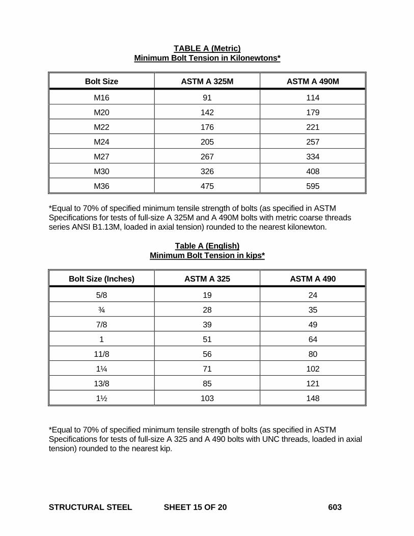
STRUCTURAL STEEL SHEET 15 OF 20 603
TABLE A (Metric) Minimum Bolt Tension in Kilonewtons*
Bolt Size ASTM A 325M ASTM A 490M
M16 91 114
M20 142 179
M22 176 221
M24 205 257
M27 267 334
M30 326 408
M36 475 595 *Equal to 70% of specified minimum tensile strength of bolts (as specified in ASTM Specifications for tests of full-size A 325M and A 490M bolts with metric coarse threads series ANSI B1.13M, loaded in axial tension) rounded to the nearest kilonewton.
Table A (English) Minimum Bolt Tension in kips*
Bolt Size (Inches) ASTM A 325 ASTM A 490
5/8 19 24
¾ 28 35
7/8 39 49
1 51 64
11/8 56 80
1¼ 71 102
13/8 85 121
1½ 103 148 *Equal to 70% of specified minimum tensile strength of bolts (as specified in ASTM Specifications for tests of full-size A 325 and A 490 bolts with UNC threads, loaded in axial tension) rounded to the nearest kip.
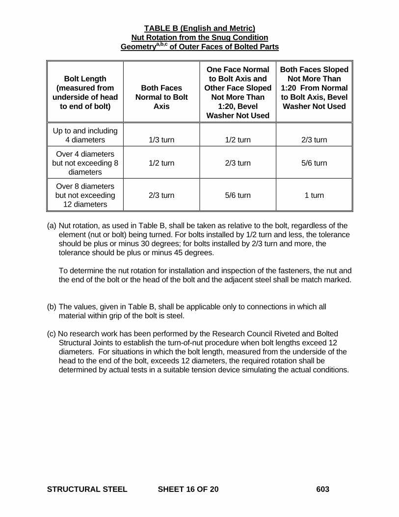
STRUCTURAL STEEL SHEET 16 OF 20 603
TABLE B (English and Metric) Nut Rotation from the Snug Condition Geometrya,b,c of Outer Faces of Bolted Parts
Bolt Length
(measured from underside of head
to end of bolt)
Both Faces Normal to Bolt
Axis
One Face Normal to Bolt Axis and
Other Face Sloped Not More Than
1:20, Bevel Washer Not Used
Both Faces Sloped Not More Than
1:20 From Normal to Bolt Axis, Bevel Washer Not Used
Up to and including 4 diameters
1/3 turn
1/2 turn
2/3 turn
Over 4 diameters but not exceeding 8
diameters
1/2 turn
2/3 turn
5/6 turn
Over 8 diameters but not exceeding
12 diameters
2/3 turn
5/6 turn
1 turn
(a) Nut rotation, as used in Table B, shall be taken as relative to the bolt, regardless of the
element (nut or bolt) being turned. For bolts installed by 1/2 turn and less, the tolerance should be plus or minus 30 degrees; for bolts installed by 2/3 turn and more, the tolerance should be plus or minus 45 degrees.
To determine the nut rotation for installation and inspection of the fasteners, the nut and
the end of the bolt or the head of the bolt and the adjacent steel shall be match marked.
(b) The values, given in Table B, shall be applicable only to connections in which all
material within grip of the bolt is steel. (c) No research work has been performed by the Research Council Riveted and Bolted
Structural Joints to establish the turn-of-nut procedure when bolt lengths exceed 12 diameters. For situations in which the bolt length, measured from the underside of the head to the end of the bolt, exceeds 12 diameters, the required rotation shall be determined by actual tests in a suitable tension device simulating the actual conditions.
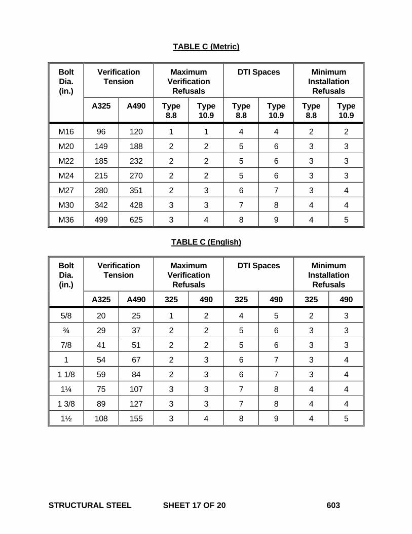
STRUCTURAL STEEL SHEET 17 OF 20 603
TABLE C (Metric)
Bolt Dia. (in.)
Verification Tension
Maximum Verification
Refusals
DTI Spaces Minimum Installation Refusals
A325 A490 Type 8.8
Type 10.9
Type 8.8
Type 10.9
Type 8.8
Type 10.9
M16 96 120 1 1 4 4 2 2
M20 149 188 2 2 5 6 3 3
M22 185 232 2 2 5 6 3 3
M24 215 270 2 2 5 6 3 3
M27 280 351 2 3 6 7 3 4
M30 342 428 3 3 7 8 4 4
M36 499 625 3 4 8 9 4 5
TABLE C (English)
Bolt Dia. (in.)
Verification Tension
Maximum Verification
Refusals
DTI Spaces Minimum Installation Refusals
A325 A490 325 490 325 490 325 490
5/8 20 25 1 2 4 5 2 3
¾ 29 37 2 2 5 6 3 3
7/8 41 51 2 2 5 6 3 3
1 54 67 2 3 6 7 3 4
1 1/8 59 84 2 3 6 7 3 4
1¼ 75 107 3 3 7 8 4 4
1 3/8 89 127 3 3 7 8 4 4
1½ 108 155 3 4 8 9 4 5
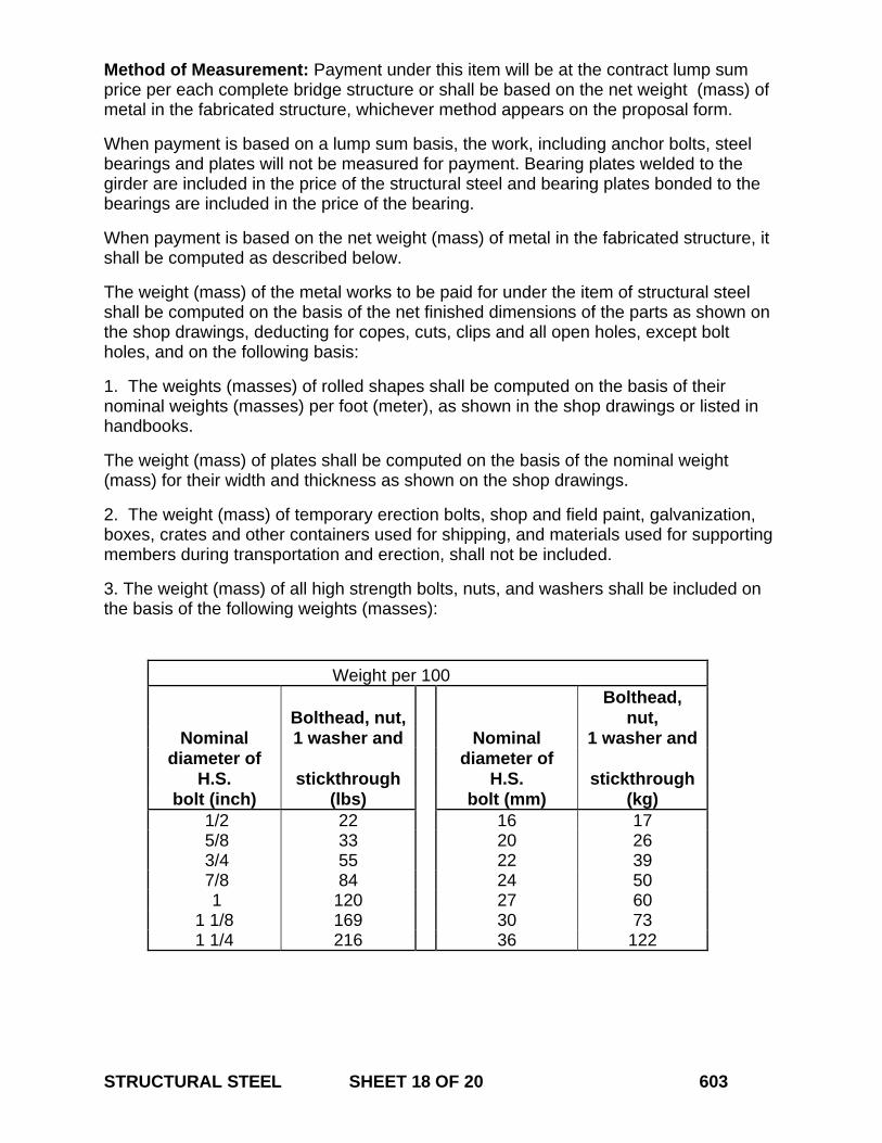
STRUCTURAL STEEL SHEET 18 OF 20 603
Method of Measurement: Payment under this item will be at the contract lump sum price per each complete bridge structure or shall be based on the net weight (mass) of metal in the fabricated structure, whichever method appears on the proposal form.
When payment is based on a lump sum basis, the work, including anchor bolts, steel bearings and plates will not be measured for payment. Bearing plates welded to the girder are included in the price of the structural steel and bearing plates bonded to the bearings are included in the price of the bearing.
When payment is based on the net weight (mass) of metal in the fabricated structure, it shall be computed as described below.
The weight (mass) of the metal works to be paid for under the item of structural steel shall be computed on the basis of the net finished dimensions of the parts as shown on the shop drawings, deducting for copes, cuts, clips and all open holes, except bolt holes, and on the following basis:
1. The weights (masses) of rolled shapes shall be computed on the basis of their nominal weights (masses) per foot (meter), as shown in the shop drawings or listed in handbooks.
The weight (mass) of plates shall be computed on the basis of the nominal weight (mass) for their width and thickness as shown on the shop drawings.
2. The weight (mass) of temporary erection bolts, shop and field paint, galvanization, boxes, crates and other containers used for shipping, and materials used for supporting members during transportation and erection, shall not be included.
3. The weight (mass) of all high strength bolts, nuts, and washers shall be included on the basis of the following weights (masses):
Weight per 100
Bolthead, nut, Bolthead,
nut, Nominal 1 washer and Nominal 1 washer and
diameter of H.S. stickthrough
diameter of H.S. stickthrough
bolt (inch) (lbs) bolt (mm) (kg) 1/2 22 16 17 5/8 33 20 26 3/4 55 22 39 7/8 84 24 50 1 120 27 60
1 1/8 169 30 73 1 1/4 216 36 122
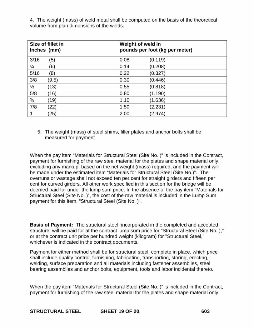
STRUCTURAL STEEL SHEET 19 OF 20 603
4. The weight (mass) of weld metal shall be computed on the basis of the theoretical volume from plan dimensions of the welds.
Size of fillet in Weight of weld in Inches (mm) pounds per foot (kg per meter)
3/16 (5) 0.08 (0.119) ¼ (6) 0.14 (0.208) 5/16 (8) 0.22 (0.327) 3/8 (9.5) 0.30 (0.446) ½ (13) 0.55 (0.818) 5/8 (16) 0.80 (1.190) ¾ (19) 1.10 (1.636) 7/8 (22) 1.50 (2.231) 1 (25) 2.00 (2.974)
5. The weight (mass) of steel shims, filler plates and anchor bolts shall be measured for payment.
When the pay item “Materials for Structural Steel (Site No. )” is included in the Contract, payment for furnishing of the raw steel material for the plates and shape material only, excluding any markup, based on the net weight (mass) required, and the payment will be made under the estimated item “Materials for Structural Steel (Site No.)”. The overruns or wastage shall not exceed ten per cent for straight girders and fifteen per cent for curved girders. All other work specified in this section for the bridge will be deemed paid for under the lump sum price. In the absence of the pay item “Materials for Structural Steel (Site No. )”, the cost of the raw material is included in the Lump Sum payment for this item, “Structural Steel (Site No. )”. Basis of Payment: The structural steel, incorporated in the completed and accepted structure, will be paid for at the contract lump sum price for "Structural Steel (Site No. )," or at the contract unit price per hundred weight (kilogram) for "Structural Steel," whichever is indicated in the contract documents.
Payment for either method shall be for structural steel, complete in place, which price shall include quality control, furnishing, fabricating, transporting, storing, erecting, welding, surface preparation and all materials including fastener assemblies, steel bearing assemblies and anchor bolts, equipment, tools and labor incidental thereto.
When the pay item “Materials for Structural Steel (Site No. )” is included in the Contract, payment for furnishing of the raw steel material for the plates and shape material only,
STRUCTURAL STEEL SHEET 20 OF 20 603
excluding any markup, based on the net weight (mass) required, and the payment will be made under the estimated item “Materials for Structural Steel (Site No.)”. All remaining work including, but not limited to, preparation of shop drawings, fabricating, transporting, storage and handling, erecting, surface preparation and all materials, equipment, tools and labor incidental thereto, will be paid for under “Structural Steel (Site No. )”. In the absence of the pay item “Materials for Structural Steel (Site No. )”, the cost of the raw material is included in the Lump Sum payment for this item, “Structural Steel (Site No. )”. All remaining work including, but not limited to, preparation of shop drawings, fabricating, transporting, storage and handling, erecting, surface preparation and all materials, equipment, tools and labor incidental thereto, will be paid for under “Structural Steel (Site No. )”.
No direct payment will be made for setting anchor bolts, preparing bearing areas, furnishing and placing materials under bearings. No direct payment will be made for non destructive testing as shown on the plans.
Pay Item Pay Unit Structural Steel (Site No. ) l.s. (l.s.) Structural Steel cwt. (kg)

July 2005
CONNECTICUT SUPPLEMENTAL SPECIFICATION
SECTION 6.12 CONCRETE CYLINDER CURING BOX
Delete the entire section and replace with it the following: 6.12.01 –Description: This item shall consist of furnishing a box for curing concrete test cylinders. The box shall be commercially available and manufactured specifically for curing concrete test cylinders. The box will remain the property of the Contractor at the conclusion of the project. The box shall be delivered to a location on the project as directed by the Engineer. 6.12.02 – Materials: A catalog cut listing detailed specifications of the box and operating instructions from the manufacturer must be submitted to the Engineer. The box and its components shall be constructed of non-corroding materials and shall be capable of storing a minimum of 18 test cylinders, 6” X 12” (152 mm X 305 mm) stored vertically with the lid closed. The lid must be watertight when closed and hinged in the back with security latches on the front that can be padlocked. The box must be capable of holding water to a maximum level of one inch above test cylinders placed in the box vertically. A drain hole must be provided in a wall of the box to allow manual drainage of the water that exceeds this level. A drain hole must also be provided at the bottom of the box so that it can be manually emptied. The temperature of the water must be controlled by heating and cooling device capable of maintaining the temperature of the water within a range of 60 to 80º F, +/- 2 ºF (15.5 to 26.7 ºC, +/- 1 ºC) within an outside ambient air temperature range of -10 to 120 º F (-23.3 to 49 ºC). The heating and cooling device must be positioned to allow free circulation of air and water around the cylinders and be rated at 120 volts and 15 amps. A rack must be provided within the box to support the cylinders above the pool of temperature controlled water. The device must be thermostatically controlled with a digital readout that is capable of displaying the high/low water temperature within the box since the last reading was taken. 6.12.03 - Construction Methods: The Contractor shall maintain the curing box in working order and shall provide all necessary electrical service and water so that the curing box can be used properly during the entire course of the project. Any curing box that is not operating properly, as determined by the Engineer, shall be replaced within 24 hours by the Contractor at no expense to the State. The Engineer reserves the right to prohibit placement of fresh concrete on the project until a curing box acceptable to the Engineer is operational on the project site. 6.12.04 - Method of Measurement: The furnishing of the concrete test cylinder curing box will be measured for payment by the number of boxes delivered by the Contractor and accepted by the Engineer. CONCRETE CYLINDER CURING BOX SHEET 1 OF 2 612
6.12.05 – Basis of Payment: This item will be paid for at the contract unit price each for “Concrete Cylinder Curing Box” ordered and accepted on the project, which price shall include all submittals, material, tools, equipment, and labor incidental thereto. The price shall also include all maintenance and operating costs related to the curing box for the duration of the project. CONCRETE CYLINDER CURING BOX SHEET 2 OF 2 612
July 2008
CONNECTICUT SUPPLEMENTAL SPECIFICATION
SECTION 6.51 CULVERTS
6.51.02 – Materials: In the 2nd paragraph replace “Gravel fill” with “Granular fill”. 6.51.03 – Construction Methods: In the 8th paragraph replace “gravel fill” with “granular fill”. Delete the 13th paragraph, “Bituminous fiber and … as the pipe.” 6.51.04 – Methods of Measurement: In the 7th paragraph replace “Gravel Fill” with “Granular Fill”. 6.51.05 – Basis of Payment: In the 8th paragraph replace “Gravel Fill” with “Granular Fill”.
CULVERTS SHEET 1 OF 1 651
July 2005
CONNECTICUT SUPPLEMENTAL SPECIFICATION
SECTION 7.02 PILES
Article 7.02.05- Basis of Payment: In the first sentence of the first paragraph of Section “2. Timber Piles” change “Furnishing Timber Piles Foot (Meter Length) and Furnishing Treated Timber Piles Foot (Meter Length)” to “Furnishing (Type) Timber Piles (Foot (Meter) Length)”. In the first sentence of the last paragraph of Section “2. Timber Piles” change “Driving Timber Piles” and “Driving Treated Timber Piles “ to “Driving (Type) Timber Piles”. Under Pay Items: Delete:
Pay Item Pay Unit Furnishing (Type) Piles (Lengths) lb. (kg) Add:
Pay Item Pay Unit Furnishing (Type) Timber Piles (Length) ea. (ea) Furnishing Steel Piles lb. (kg) Furnishing (Type) Prestressed Concrete Piles l.f. (m) Cast-in-Place Concrete Piles l.f. (m)
PILES SHEET 1 OF 1 702
January 2009
CONNECTICUT SUPPLEMENTAL SPECIFICATION
SECTION 8.22 TEMPORARY PRECAST CONCRETE BARRIER CURB
Article 8.22.04 – Method of Measurement: Add the following sentence to the end of the second paragraph: “Relocation of Temporary Precast Concrete Barrier Curb for access to the work area or for the convenience of the Contractor shall be considered incidental to Maintenance and Protection of Traffic and will not be measured for payment.”
TEMPORARY PRECAST CONCRETE BARRIER CURB SHEET 1 OF 1 822
January 2005
CONNECTICUT SUPPLEMENTAL SPECIFICATION
SECTION 9.10 METAL BEAM RAIL
Article 9.10.04 – Method of Measurement Subarticle 1 – Metal Beam Rail (Type)
Delete the only sentence and replace with the following:
The length of metal beam rail measured for payment will be the number of linear feet (meters) of accepted rail of the type or designation installed, including radius rail other than Curved Guide Rail Treatment, measured along the top of rail between centers of end posts in each continuous section.
METAL BEAM RAIL SHEET 1 OF 1 910
July 2006
CONNECTICUT SUPPLEMENTAL SPECIFICATION
SECTION 9.18 THREE CABLE GUIDE RAILING
(I-BEAM POSTS) AND ANCHORAGES 9.18.03 – Construction Methods: In the 10th paragraph, replace “MIL” with “MILSPEC.”
THREE CABLE GUIDE RAILING (I-BEAM POSTS) AND ANCHORAGES SHEET 1 OF 1 918
January 2010
CONNECTICUT SUPPLEMENTAL SPECIFICATION
SECTION 9.22 BITUMINOUS CONCRETE SIDEWALK BITUMINOUS CONCRETE DRIVEWAY
9.22.03 – Construction Methods: Replace the first paragraph with the following:
“1. Excavation: Excavation, including saw cutting, removal of any existing sidewalk, or driveway, shall be made to the required depth below the finished grade, as shown on the plans or as directed by the Engineer. All soft and yielding material shall be removed and replaced with suitable material.”
9.22.05 – Basis of Payment: Replace the only paragraph with the following: “This work will be paid for at the contract unit price per square yard (square meter) for "Bituminous Concrete Sidewalk" or "Bituminous Concrete Driveway," as the case may be, complete in place, which price shall include all saw cutting, excavation as specified above, backfill, disposal of surplus material, gravel or reclaimed miscellaneous aggregate base, and all equipment, tools, labor and materials incidental thereto.”
BITUMINOUS CONCRETE SIDEWALK BITUMINOUS CONCRETE DRIVEWAY SHEET 1 OF 1 922
January 2010
CONNECTICUT SUPPLEMENTAL SPECIFICATION
SECTION 9.44 TOPSOIL
Add the following paragraph to the beginning of article 9.44.03 – Construction Methods: “The Contractor shall notify the Engineer of the location of the topsoil at least 15 calendar days prior to delivery. The topsoil and its source shall be inspected and approved by the Engineer before the material is delivered to the project. Any material delivered to the project, which does not meet specifications or which has become mixed with undue amounts of subsoil during any operation at the source or during placing and spreading, will be rejected and shall be replaced by the Contractor with acceptable material.”
TOPSOIL SHEET 1 OF 1 944
January 2010
CONNECTICUT SUPPLEMENTAL SPECIFICATION
SECTION 9.49 FURNISHING, PLANTING and MULCHING
TREES, SHRUBS, VINES and GROUND COVER PLANTS 9.49.03 – Construction Methods: Replace subsection 5. Pits with the following:
“5. Pits: The pit diameters shall be twice the diameter of the root-spread or container diameters, and shall be 2- inches (50 millimeters) less than the height of the rootball measured from the bottom of the ball to the root collar. (i. e. A 12-inch (300 millimeters) measurement between the root collar and the bottom of the rootball will require a 10-inch (250 millimeters) deep pit). Any excavation in excess of that required shall be replaced with planting soil and compacted to the satisfaction of the Engineer.”
Add the following sentence to subsection 6. Obstructions Below Ground: “If removal of obstructions results in a deeper hole than needed for planting, backfill material shall be added and compacted to the satisfaction of the Engineer.” Replace subsection 7. Preparation of Backfill with the following:
“7. Backfill: Backfill shall conform to M.13.01-1 Planting Soil.” Replace subsection 8. Setting Plants with the following:
“8. Setting Plants: All plants shall be plumb and at a level that is 2-inches (50 millimeters) higher than the surrounding ground. Backfill material for all plants shall be thoroughly and properly settled by firming or tamping. Thorough watering shall accompany backfilling. Saucers capable of holding water shall be formed at individual plants (exclusive of plant beds) by placing ridges of planting soil around each, or as directed by the Engineer. a. Balled and Burlapped plants: Plants shall be handled in such manner so that the soil will not be loosened from the roots inside of the ball. Carefully place the plant into the prepared pits and backfill with planting soil to one - half the depth of the pit, thoroughly tamp to the satisfaction of the Engineer around the ball. Fill the remaining area of the pit with water. Once water has completely drained, loosen the burlap and peel down the top one third. If wire baskets are used, cut and bend down the top third of the basket. Roots that have been wrapped around the ball within the burlap shall be straightened and the remainder of the pit filled with planting soil tamped to ensure that no air pockets remain.
FURNISHING, PLANTING and MULCHING TREES, SHRUBS, VINES and GROUND COVER PLANTS SHEET 1 OF 3 949
b. Container Grown Plants: Carefully remove the plant from the container over the prepared pits. Gently loosen the soil and straighten all roots as naturally as possible. Place into the bottom of the pit. Backfill with planting soil to one - half the depth of the pit. Thoroughly tamp to the satisfaction of the Engineer. Fill remaining area of the pit with water. Once water has completely drained fill the remainder of the pit with planting soil tamped to ensure that no air pockets remain.
c. Bare-roots Plants: Carefully spread roots as naturally as possible and place into the bottom of the pit. All broken or frayed roots shall be cleanly cut off. Backfill with planting soil to one - half the depth of the pit. Thoroughly tamp to the satisfaction of the Engineer. Fill remaining area of the pit with water. Once water has completely drained fill the remainder of the pit with planting soil tamped to ensure that no air pockets remain.”
Replace subsection 10. Watering with the following:
“10. Watering: All plants shall be watered upon setting and as many times thereafter as conditions warrant. The following is a guide for minimum requirements: Trees: 2 ½” Caliper and less – Fifteen (15) gallons each. 3” to 5” Caliper – Twenty (20) gallon each. 5 ½” Caliper and above – Twenty-five (25) gallon each. Shrubs: 24” and less – Six (6) gallon each. More than 24”- Ten (10) gallon each. Vines, Perennials, and Ornamental Grasses – Three (3) gallons each. Groundcovers and Bulbs – Two (2) gallons per square foot. Water shall be applied at a controlled rate and in such a manner to ensure that the water reaches the root zone (saucer) of the plant or plant bed and does not run off to adjacent areas. Watering shall be applied in a manner that does not dislodge plants, erode soil or mulch, or cause damage to saucer. The Contractor may use slow-release, drip irrigation bags for watering in accordance with manufacturer’s instructions. The use of these portable/temporary irrigation bags will require the approval of the Engineer.
Overhead hydro-seeder spray nozzles shall not be used as watering devices.”
Replace subsection 17. Establishment Period with the following:
“17. One-Year Establishment Period: All plant material shall be subject to a One-Year Establishment Period. During this time, the Contractor shall use currently accepted horticultural practices to keep all plant material installed in a healthy, vigorous growing condition at the date of final acceptance. The date of final
FURNISHING, PLANTING and MULCHING TREES, SHRUBS, VINES and GROUND COVER PLANTS SHEET 2 OF 3 949
acceptance shall be one full calendar year following the satisfactory completion of the planting activities as confirmed by the Engineer. An inspection will be held one year from the date of installation with the Contractor, Engineer, and Landscape Designer to determine the acceptability of the plant establishment. An inventory of losses and rejected materials will be made and corrective and necessary clean up measures will be determined at the plant inspection.”
FURNISHING, PLANTING and MULCHING TREES, SHRUBS, VINES and GROUND COVER PLANTS SHEET 3 OF 3 949
January 2009
CONNECTICUT SUPPLEMENTAL SPECIFICATION
SECTION 9.75 MOBILIZATION
9.75.04 – Method of Measurement: Delete the entire section and replace with the following: This work will be measured for payment in the manner described hereinafter; however, the determination of the total contract price earned shall not include the amount of mobilization earned during the period covered by the current monthly estimate- but shall include amounts previously earned and certified for payment: 1. When the first payment estimate is made, 25 percent of the lump sum bid price for this item or 2.5 percent of the total original contract price, whichever is less, shall be certified for payment. 2. When the Baseline Schedule, as specified under Section 1.05.08, is accepted, 50 percent of the lump sum bid price or 5 percent of the total original contract price, whichever is less, minus any previous payments, will be certified for payment. 3. When 10 percent of the total original contract price is earned and the Baseline Schedule, as specified under Section 1.05.08, is accepted, 75 percent of the lump sum price of this item or 7.5 percent of the total original contract price, whichever is less, minus any previous payments, will be certified for payment. 4. When 30 percent of the total original contract price is earned and the Baseline Schedule, as specified under Section 1.05.08, is accepted, 100 percent of the lump sum price of this item or 10 percent of the total original contract price, whichever is less, minus any previous payments, will be certified for payment. Upon completion of all work on the project, payment of any amount bid for mobilization in excess of 10 percent of the original contract amount will be paid. Nothing herein shall be construed to limit or preclude partial payments otherwise provided for by the contract.
MOBILIZATION SHEET 1 OF 1 975
July 2010
CONNECTICUT SUPPLEMENTAL SPECIFICATION
SECTION 10.01 TRENCHING AND BACKFILLING
Article 10.01.01- Description: In the only sentence of the first paragraph after “…satisfactory…” add the following: “clean-up and”. In the only sentence of the second paragraph after “…reconstruction of…” add the following: “bituminous, concrete and granite curbing,”. Article 10.01.05- Basis of Payment: In the only sentence of the second paragraph after “…mulching…” add the following: “clean-up and”. After “…installing…” add the word “curbing,”. At the end of the third paragraph, add the following: “In the absence of a “Rock in Trench Excavation” item, the work will be compensated as extra work.” In the only sentence of the sixth paragraph, after …”…unit price for ’Concrete Sidewalk’…” add the following: “or as extra work, if no unit price has been established.”
TRENCHING AND BACKFILLING SHEET 1 OF 1 1001
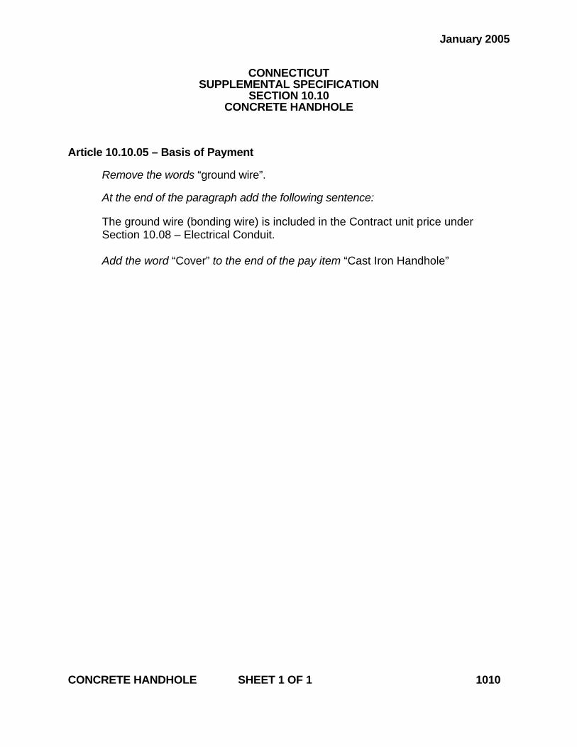
January 2005
CONNECTICUT SUPPLEMENTAL SPECIFICATION
SECTION 10.10 CONCRETE HANDHOLE
Article 10.10.05 – Basis of Payment Remove the words “ground wire”.
At the end of the paragraph add the following sentence:
The ground wire (bonding wire) is included in the Contract unit price under Section 10.08 – Electrical Conduit. Add the word “Cover” to the end of the pay item “Cast Iron Handhole”
CONCRETE HANDHOLE SHEET 1 OF 1 1010
July 2006
CONNECTICUT SUPPLEMENTAL SPECIFICATION
SECTION 11.13 CONTROL CABLE
11.13.03 – Construction Methods: In the 1st paragraph of subsection 2 replace “MIL” with “MILSPEC.”
CONTROL CABLE SHEET 1 OF 1 1113

January 2007
CONNECTICUT SUPPLEMENTAL SPECIFICATION
SECTION 12.10 EPOXY RESIN PAVEMENT MARKINGS, SYMBOLS AND LEGENDS
12.10.03 (2) – Procedures:
Insert the following after the sixth paragraph:
The epoxy shall be uniformly applied to the surface to be marked to ensure a wet film thickness of the applied epoxy, without glass beads, of 20 mils +/- 1 mil (500 um +/- 25 um).
EPOXY RESIN PAVEMENT MARKINGS, SYMBOLS AND LEGENDS SHEET 1 OF 1 1210
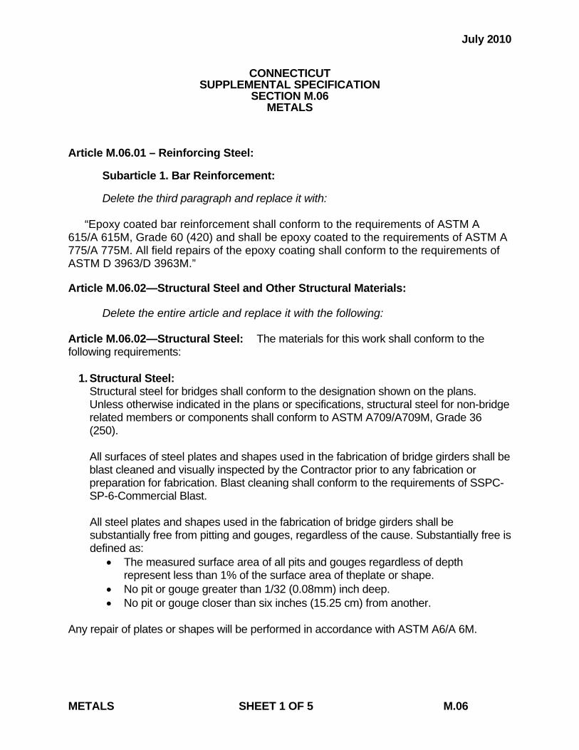
July 2010
CONNECTICUT SUPPLEMENTAL SPECIFICATION
SECTION M.06 METALS
Article M.06.01 – Reinforcing Steel: Subarticle 1. Bar Reinforcement: Delete the third paragraph and replace it with:
“Epoxy coated bar reinforcement shall conform to the requirements of ASTM A 615/A 615M, Grade 60 (420) and shall be epoxy coated to the requirements of ASTM A 775/A 775M. All field repairs of the epoxy coating shall conform to the requirements of ASTM D 3963/D 3963M.”
Article M.06.02—Structural Steel and Other Structural Materials: Delete the entire article and replace it with the following: Article M.06.02—Structural Steel: The materials for this work shall conform to the following requirements: 1. Structural Steel: Structural steel for bridges shall conform to the designation shown on the plans. Unless otherwise indicated in the plans or specifications, structural steel for non-bridge
related members or components shall conform to ASTM A709/A709M, Grade 36 (250).
All surfaces of steel plates and shapes used in the fabrication of bridge girders shall be
blast cleaned and visually inspected by the Contractor prior to any fabrication or preparation for fabrication. Blast cleaning shall conform to the requirements of SSPC-SP-6-Commercial Blast.
All steel plates and shapes used in the fabrication of bridge girders shall be substantially free from pitting and gouges, regardless of the cause. Substantially free is defined as:
• The measured surface area of all pits and gouges regardless of depth represent less than 1% of the surface area of theplate or shape.
• No pit or gouge greater than 1/32 (0.08mm) inch deep. • No pit or gouge closer than six inches (15.25 cm) from another.
Any repair of plates or shapes will be performed in accordance with ASTM A6/A 6M.
METALS SHEET 1 OF 5 M.06
2. Anchor Bolts: Unless otherwise designated on the plans, anchor bolts, including suitable nuts and
washers, shall conform to the following requirements:
Anchor bolt assemblies shall conform to the requirements of ASTM F1554, Grade 36 (250). All components of the bolt assembly shall be galvanized in conformance with ASTM A 153/A 153M. Certified Test Reports and Material Samples: The Contractor shall submit notarized copies of Certified Test Reports in conformance with Article 1.06.07. Prior to incorporation into the work, the Contractor shall submit samples of the anchor bolt assemblies to the Engineer for testing in accordance with the latest edition of the “Schedule of Minimum Requirements for Acceptance Testing”. One sample shall be submitted for each diameter, material designation, grade or coating of anchor bolt assembly.
3. High Strength Bolts: High strength bolts, including suitable nuts and hardened
washers, shall conform to the following requirements: a) High strength bolts shall conform to ASTM A325 or ASTM A490 as shown on
the plans. High-strength bolts used with coated steel shall be mechanically galvanized, unless otherwise specified. High-strength bolts used with uncoated weathering grades of steel shall be Type 3.
Nuts for ASTM A325 bolts shall conform to ASTM A563, grades DH, DH3, C, C3 and D. Where galvanized high-strength bolts are used, the nuts shall be galvanized, heat treated grade DH or DH3. Where Type 3 high-strength bolts are used, the nuts shall be grade C3 or DH3. Nuts for ASTM A490 bolts shall conform to the requirements of ASTM A563, grades DH and DH3. Where Type 3 high-strength bolts are used, the nuts shall be grade DH3. All galvanized nuts shall be lubricated with a lubricant containing a visible dye of any color that contrasts with the color of the galvanizing. Black bolts must be oily to the touch when delivered and installed. Circular flat and square or rectangular beveled, hardened steel washers shall conform to ASTM F436. Unless otherwise specified, galvanized washers shall be furnished when galvanized high-strength bolts are specified, and washers with atmospheric corrosion resistance and weathering characteristics shall be furnished when Type 3 high-strength bolts are specified. Compressible-washer-type direct tension indicator washers, used in conjunction with high strength bolts, shall conform to ASTM F959. Where galvanized high-strength bolts are used, the washers shall be galvanized in accordance with ASTM B695, Class 50. Where Type 3 high-strength bolts are used, the washers shall be galvanized in accordance with ASTM B695, Class 50 and coated with epoxy.
METALS SHEET 2 OF 5 M.06
b) Identifying Marks: ASTM A325 for bolts and the specifications referenced therein for nuts require that bolts and nuts manufactured to the specification be identified by specific markings on the top of the bolt head and on one face of the nut. Head markings must identify the grade by the symbol "A325", the manufacturer and the type, if Type 2 or 3. Nut markings must identify the grade, the manufacturer and if Type 3, the type. Markings on direct tension indicators must identify the manufacturer and Type "325". Other washer markings must identify the manufacturer and if Type 3, the type.
ASTM A490 for bolts and the specifications reference therein for nuts require that bolts and nuts manufactured to the specifications be identified by specific markings on the top of the bolt head and on one face of the nut. Head markings must identify the grade by the symbol "A490", the manufacturer and the type, if Type 2 or 3. Nut markings must identify the grade, the manufacturer and if Type 3, the type. Markings on direct tension indicators must identify the manufacturer and Type "490". Other washer markings must identify the manufacturer and if Type 3, the type.
c) Dimensions: Bolt and nuts dimensions shall conform to the requirements for
Heavy Hexagon Structural Bolts and for Heavy Semi-Finished Hexagon Nuts given in ANSI Standard B18.2.1 and B18.2.2, respectively.
d) Galvanized Bolts: Galvanized bolts shall conform to ASTM A325, Type 1.
The bolts shall be hot-dip galvanized in accordance with ASTM A153, Class C or mechanically galvanized in accordance with ASTM B695, Class 50. Bolts, nuts, and washers of any assembly shall be galvanized by the same process. The nuts shall be overtapped to the minimum amount required for the fastener assembly, and shall be lubricated with a lubricant containing a visible dye so a visual check can be made for the lubricant at the time of field installation. Galvanized bolts shall be tension tested after galvanizing. ASTM A 490 bolts shall not be galvanized.
e) Test Requirements: The maximum hardness of A325 bolts 1" or less in
diameter shall be 33 HRC. Plain, ungalvanized nuts shall have a minimum hardness of 89 HRB. Proof load tests, in accordance with the requirements of ASTM F606 Method 1, shall be required for the bolts. Wedge tests of full-size bolts are required in accordance with Section 8.3 of ASTM A325. Galvanized bolts shall be wedge tested after galvanizing. Proof load tests of ASTM A563 are required for nuts. Proof load tests for nuts used with galvanized bolts shall be performed after galvanizing, overtapping and lubricating.
METALS SHEET 3 OF 5 M.06
Rotational-capacity tests are required and shall be performed on all plain or galvanized (after galvanizing) bolt, nut and washer assemblies by the manufacturer or distributor prior to shipping and by the Contractor at the job site. The thickness of galvanizing on bolts, nuts and washers shall be measured. On bolts, it shall be measured on the wrench flats or on top of the bolt head, and on nuts it shall be measured on the wrench flats.
f) Certified Test Reports and Materials Certificates: The Contractor shall
submit notarized copies of Certified Test Reports and Materials Certificates in conformance with Article 1.06.07 for fastener assemblies. In addition the Certified Test Reports and Materials Certificates shall include the following:
a. Mill test reports shall indicate the place where the material was
melted and manufactured. b. Test reports for proof load tests, wedge tests, and rotational-
capacity tests shall indicate where the tests were performed, date of tests, location of where the components were manufactured and lot numbers.
c. The test report for galvanized components shall indicate the
thickness of the galvanizing.
g) Material Samples: Prior to incorporation into the work, the Contractor shall submit samples of the bolt assemblies to the Engineer for testing in accordance with the latest edition of the “Schedule of Minimum Requirements for Acceptance Testing”. Samples shall be submitted for each diameter, length, material designation, grade, coating and manufacturer of bolt assembly.
4. Welded Stud Shear Connectors:
a) Materials: Stud shear connectors shall conform to the requirements of ASTM A 108, cold-drawn bar, Grades 1015, 1018 or 1020, either semi- or fully-killed. If flux-retaining caps are used, the steel for the caps shall be of a low carbon grade suitable for welding and shall comply with ASTM A 109.
Stud shear connectors shall be of a design suitable for electrically end-welding to steel with automatically timed stud welding equipment. The studs shall be of the sizes and dimensions noted on the plans. Flux for welding shall be furnished with each stud, either attached to the end of the stud or combined with the arc shield for automatic application in the welding operation. Each stud shall be furnished with a disposable ferrule of sufficient strength to remain intact during the welding operation and not crumble or break; it shall not be detrimental to the weld or create excessive slag.
METALS SHEET 4 OF 5 M.06
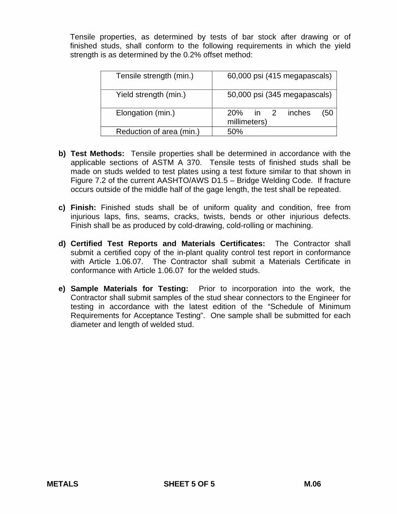
Tensile properties, as determined by tests of bar stock after drawing or of finished studs, shall conform to the following requirements in which the yield strength is as determined by the 0.2% offset method:
b) Test Methods: Tensile properties shall be determined in accordance with the
applicable sections of ASTM A 370. Tensile tests of finished studs shall be made on studs welded to test plates using a test fixture similar to that shown in Figure 7.2 of the current AASHTO/AWS D1.5 – Bridge Welding Code. If fracture occurs outside of the middle half of the gage length, the test shall be repeated.
c) Finish: Finished studs shall be of uniform quality and condition, free from
injurious laps, fins, seams, cracks, twists, bends or other injurious defects. Finish shall be as produced by cold-drawing, cold-rolling or machining.
d) Certified Test Reports and Materials Certificates: The Contractor shall
submit a certified copy of the in-plant quality control test report in conformance with Article 1.06.07. The Contractor shall submit a Materials Certificate in conformance with Article 1.06.07 for the welded studs.
e) Sample Materials for Testing: Prior to incorporation into the work, the
Contractor shall submit samples of the stud shear connectors to the Engineer for testing in accordance with the latest edition of the “Schedule of Minimum Requirements for Acceptance Testing”. One sample shall be submitted for each diameter and length of welded stud.
METALS SHEET 5 OF 5 M.06
Tensile strength (min.) 60,000 psi (415 megapascals)
Yield strength (min.) 50,000 psi (345 megapascals)
Elongation (min.) 20% in 2 inches (50 millimeters)
Reduction of area (min.) 50%
January 2010
CONNECTICUT SUPPLEMENTAL SPECIFICATION
SECTION M.13 ROADSIDE DEVELOPMENT
Delete article M.13.01 – Topsoil and replace it with the following: “Article M.13.01 – Topsoil: The term topsoil used herein shall mean a soil meeting the soil textural classes established by the USDA Classification System based upon the proportion of sand, silt, and clay size particles after passing a No. 10 (2 millimeter) sieve and subjected to a particle size analysis. The topsoil shall contain 5% to 20% organic matter as determined by loss on ignition of oven-dried samples dried at 221° F (105° C). The pH range of the topsoil shall be 5.5 to 7.0. The following textural classes shall be acceptable:
Loamy sand, including coarse, loamy fine, and loamy very fine sand, with not more than 80% sand Sandy loam, including coarse, fine and very fine sandy loam Loam Clay loam, with not more than 30% clay Silt loam, with not more than 60% silt Sandy clay loam, with not more than 30% clay All textural classes of topsoil with greater than 80% sand content will be rejected.
The topsoil furnished by the Contractor shall be a natural, workable soil that is screened and free of subsoil, refuse, stumps, roots, brush, weeds, rocks and stones over 1 1/4 inches (30 millimeters) in diameter, and any other foreign matter that would be detrimental to the proper development of plant growth. The Contractor shall notify the Engineer of the location of the topsoil at least 15 calendar days prior to delivery. The topsoil and its source shall be inspected and approved by the Engineer before the material is delivered to the project. Any material delivered to the project, which does not meet specifications or which has become mixed with undue amounts of subsoil during any operation at the source or during placing and spreading, will be rejected and shall be replaced by the Contractor with acceptable material. When topsoil is not furnished by the Contractor, it shall be material that is stripped in accordance with Section 2.02 or is furnished by the State, and will be tested as determined by the Engineer. 1. Planting Soil: Soil Material to be used for plant backfill shall be one of the following textural classes:
Loamy sand, with not more than 80% sand Sandy loam Loam Clay loam, with not more than 30% clay Silt loam, with not more than 60% silt Sandy clay loam, with not more than 30% clay
ROADSIDE DEVELOPMENT SHEET 1 OF 2 M.13
Planting soil shall be premixed, consisting of approximately 50 % topsoil, 25 % compost or peat, and 25% native soil. Planting soil shall be loose, friable, and free from refuse, stumps, roots, brush, weeds, rocks and stones 2 inches (50 millimeters) in diameter. In addition, the material shall be free from any material that will prevent proper development and plant growth.
(a) For ericaceous plants and broad-leaved evergreens requiring an acid soil, planting soil shall have a true pH of 4.5 to 5.5. If it has not, it shall be amended by the Contractor at his own expense to the proper pH range by mixing with sulphur.
(b) Planting soil for general planting of nonacid-loving plants shall have a true pH value of 5.6 to 6.5. If it has not, it shall be amended by the Contractor at his own expense to the proper pH range by mixing with dolomitic limestone.
The amount of either sulphur or limestone required to adjust the planting soil to the proper pH range (above) shall be determined by the Engineer based on agronomic tests. The limestone shall conform to the requirements of Article M.13.02. The sulphur shall be commercial or flour sulphur, unadulterated, and shall be delivered in containers with the name of the manufacturer, material, analysis, and net weight (mass) appearing on each container. The Engineer reserves the right to draw such samples and to perform such tests as he deems necessary to ensure that these specifications are met.”
ROADSIDE DEVELOPMENT SHEET 2 OF 2 M.13
July 2012
CONNECTICUT SUPPLEMENTAL SPECIFICATION
SECTION M.16 TRAFFIC CONTROL SIGNALS
Article M.16.04 – Poles: Subarticle 1. Steel Poles: (i) Wire Entrance Fitting:
In the second sentence, delete “required to accept the cables”.
Article M.16.06 – Traffic Signals: In the 1st paragraph of subsection 9 replace “MIL” with “MILSPEC”. Under the paragraph entitled Third Coat, replace the first two sentence with the following:
“ Dark Green Enamel: Shall be Dark Green exterior baked enamel and shall comply with FS A-A 2962. The color shall be No. 14056, FS No. 595.”
and in the third sentence replace “MIL” with “MILSPEC.”
Article M.16.08 – Pedestrian Push Button Subarticle – Painting
Delete the entire “Third Coat” paragraph and replace with the following:
Third Coat: Dark Green Enamel, shall be DARK GREEN exterior-baking enamel and shall comply with Federal Specifications A-A 2962. The color shall be No. 14056, Federal Standard No. 595.
M.16.15 – Messenger and Span Wire:
Delete the entire article and replace with the following: The materials for this work shall conform to the following requirements: 1. Messenger wire shall be made of double-galvanized 7-strand utilities-grade steel wire cable, not less than 3/16 inch (4.8 millimeters) in diameter, with at least a 2,400-pound (10.7-killinewton) breaking strength. TRAFFIC CONTROL SIGNALS SHEET 1 OF 2 M.16
2. Span wire: (a) “Span wire” shall be made of double-galvanized 7-strand utilities-grade steel wire cable, not less than 3/8 inch (9.5 millimeters) in diameter, with at least an 11,200-pound (50-kilonewton) breaking strength. (b) “Span wire (high strength)” shall be made of double-galvanized 7-strand extra-high-strength-grade steel wire cable, not less than 7/16 inch (11.1 millimeters) in diameter, with at least a 20,800-pound (94-kilonewton) breaking strength. 3. All hardware accessories shown on the plans to be used in span wire or messenger mounting shall be made of high-strength, double-galvanized, first-quality materials.
TRAFFIC CONTROL SIGNALS SHEET 2 OF 2 M.16
July 2006
CONNECTICUT SUPPLEMENTAL SPECIFICATION
SECTION M.17 ELASTOMERIC MATERIALS
M.17.01 – Elastomeric Bearing Pads: In the 2nd paragraph of subsection 4(b), replace “MS MIL” with “MILSPEC.”
ELASTOMERIC MATERIALS SHEET 1 OF 1 M.17
July 2006
CONNECTICUT SUPPLEMENTAL SPECIFICATION
SECTION M.18 SIGNING
M.18.10 – Demountable Copy: In the chart under subsection 3H, replace “MS MIL” with “MILSPEC.”
SIGNING SHEET 1 OF 1 M.18