Embed Size (px)
Citation preview
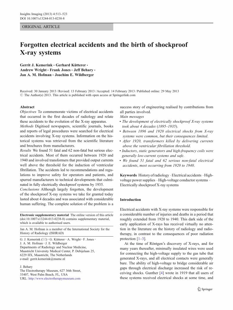
ORIGINAL ARTICLE
Forgotten electrical accidents and the birth of shockproofX-ray systems
Gerrit J. Kemerink & Gerhard Kütterer &
Andrew Wright & Frank Jones & Jeff Behary &
Jan A. M. Hofman & Joachim E. Wildberger
Received: 30 January 2013 /Revised: 13 February 2013 /Accepted: 14 February 2013 /Published online: 29 May 2013# The Author(s) 2013. This article is published with open access at Springerlink.com
AbstractObjectives To commemorate victims of electrical accidentsthat occurred in the first decades of radiology and relatethese accidents to the evolution of the X-ray apparatus.Methods Digitised newspapers, scientific journals, booksand reports of legal procedures were searched for electricalaccidents involving X-ray systems. Information on the his-torical systems was retrieved from the scientific literatureand brochures from manufacturers.Results We found 51 fatal and 62 non-fatal but serious elec-trical accidents. Most of them occurred between 1920 and1940 and involved transformers that provided output currentswell above the threshold for the induction of ventricularfibrillation. The accidents led to recommendations and regu-lations to improve safety for operators and patients, andspurred manufacturers to technical developments that culmi-nated in fully electrically shockproof systems by 1935.Conclusions Although largely forgotten, the developmentof the shockproof X-ray systems we take for granted todaylasted about 4 decades and was associated with considerablehuman suffering. The complete solution of the problem is a
success story of engineering realised by contributions fromall parties involved.Main messages• The development of electrically shockproof X-ray systemstook about 4 decades (1895–1935).
• Between 1896 and 1920 electrical shocks from X-raysystems were common, but their consequences limited.
• After 1920, transformers killed by delivering currentsabove the ventricular fibrillation threshold.
• Inductors, static generators and high-frequency coils weregenerally low-current systems and safe.
• We found 51 fatal and 62 serious non-fatal electricalaccidents, most occurring from 1920 to 1940.
Keywords Historyof radiology .Electrical accidents .High-voltage power supplies . High-voltage conductor systems .
Electrically shockproof X-ray systems
Introduction
Electrical accidents with X-ray systems were responsible fora considerable number of injuries and deaths in a period thatroughly extended from 1920 to 1940. This dark side of theearly application of X-rays has received virtually no atten-tion in the literature on the history of radiology and radio-therapy, in contrast to the consequences of poor radiationprotection [1–3].
At the time of Röntgen’s discovery of X-rays, and formany years thereafter, minimally insulated wires were usedfor connecting the high-voltage supply to the gas tube thatgenerated X-rays, and all electrical contacts were generallybare. The ability of high-voltage to bridge considerable airgaps through electrical discharge increased the risk of re-ceiving shocks. Gunther [4] wrote in 1919 that all users ofthese systems received electrical shocks at some time, and
Electronic supplementary material The online version of this article(doi:10.1007/s13244-013-0238-8) contains supplementary material,which is available to authorised users.
Jan A. M. Hofman is a member of the International Society for theHistory of Radiology (ISHRAD)
G. J. Kemerink (*) :G. Kütterer :A. Wright : F. Jones :J. A. M. Hofman : J. E. WildbergerDepartments of Radiology and Nuclear Medicine,Maastricht University Medical Center, P. Debijelaan 25,6229 HX, Maastricht, The Netherlandse-mail: [email protected]
J. BeharyThe Electrotherapy Museum, 627 36th Street,33407, West Palm Beach, FL, USAURL: http://www.electrotherapymuseum.com
Insights Imaging (2013) 4:513–523DOI 10.1007/s13244-013-0238-8
although the shocks were painful and could cause burns, theimpact on the victim’s health (and attitude) was minimal.The high-voltage generators of this period primarilyconsisted of induction coils, static generators and high-frequency coils of low electrical power. Apart from thedanger of personal electrical shock, risk of fire existed inplaces where inflammable, volatile anaesthetics were used.Moreover, corona discharges around exposed high tensionwere responsible for the formation of noxious nitrogenoxides and ozone. Over time, wiring configurations receivedconsiderable attention, but wires and contacts still remainedpartially unprotected. The potential danger of X-ray ma-chines increased after the development of high-voltagetransformers, which allowed for an increase in electricalpower. Ensuing fatal and serious non-fatal accidents incitedseveral authors to formulate safety recommendations [4–6],which ultimately led to legislation [7, 8]. Though manufac-turers developed many modifications to improve electricalsafety, it was not until around 1935 that new X-ray systemsmight be considered electrically safe for the patient andoperator (see Grigg [9] for many historical details).
In this work we present the lethal and serious non-lethalaccidents we were able to retrieve from the literature. Toprovide a context for how the accidents occurred and howthey contributed to the development of electrically shock-proof X-ray systems, the following subjects will beaddressed: (1) electrical current and the human body, (2)high-voltage power supplies used in X-ray systems, (3) X-ray tubes, (4) wiring of X-ray systems, (5) safety recom-mendations and legislation, (6) victims of electrical shock,(7) types of electrical accidents.
Electrical current and the human body
The magnitude of the electrical current passing throughhuman tissue is the main determinant of its effect. Therefore,
it makes sense to first look at the effects of mains-likevoltages, as these have been studied in great detail [10, 11].
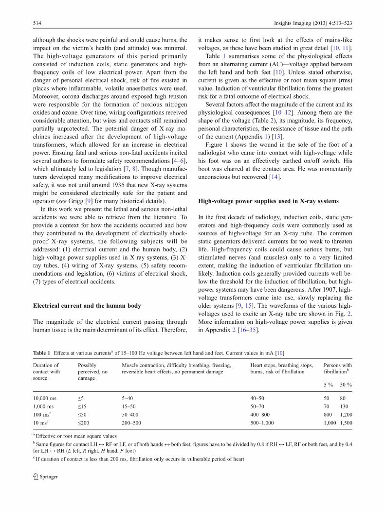
Table 1 summarises some of the physiological effectsfrom an alternating current (AC)—voltage applied betweenthe left hand and both feet [10]. Unless stated otherwise,current is given as the effective or root mean square (rms)value. Induction of ventricular fibrillation forms the greatestrisk for a fatal outcome of electrical shock.
Several factors affect the magnitude of the current and itsphysiological consequences [10–12]. Among them are theshape of the voltage (Table 2), its magnitude, its frequency,personal characteristics, the resistance of tissue and the pathof the current (Appendix 1) [13].
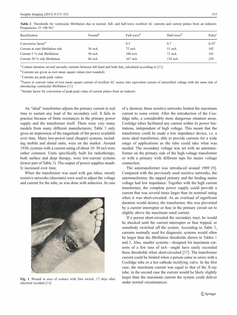
Figure 1 shows the wound in the sole of the foot of aradiologist who came into contact with high-voltage whilehis foot was on an effectively earthed on/off switch. Hisboot was charred at the contact area. He was momentarilyunconscious but recovered [14].
High-voltage power supplies used in X-ray systems
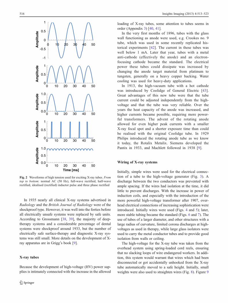
In the first decade of radiology, induction coils, static gen-erators and high-frequency coils were commonly used assources of high-voltage for an X-ray tube. The commonstatic generators delivered currents far too weak to threatenlife. High-frequency coils could cause serious burns, butstimulated nerves (and muscles) only to a very limitedextent, making the induction of ventricular fibrillation un-likely. Induction coils generally provided currents well be-low the threshold for the induction of fibrillation, but high-power systems may have been dangerous. After 1907, high-voltage transformers came into use, slowly replacing theolder systems [9, 15]. The waveforms of the various high-voltages used to excite an X-ray tube are shown in Fig. 2.More information on high-voltage power supplies is givenin Appendix 2 [16–35].
Table 1 Effects at various currentsa of 15–100 Hz voltage between left hand and feet. Current values in mA [10]
Duration ofcontact withsource
Possiblyperceived, nodamage
Muscle contraction, difficulty breathing, freezing,reversible heart effects, no permanent damage
Heart stops, breathing stops,burns, risk of fibrillation
Persons withfibrillationb
5 % 50 %
10,000 ms ≤5 5–40 40–50 50 80
1,000 ms ≤15 15–50 50–70 70 130
100 msc ≤50 50–400 400–800 800 1,200
10 msc ≤200 200–500 500–1,000 1,000 1,500
a Effective or root mean square valuesb Same figures for contact LH↔ RF or LF, or of both hands↔ both feet; figures have to be divided by 0.8 if RH↔ LF, RF or both feet, and by 0.4for LH ↔ RH (L left, R right, H hand, F foot)c If duration of contact is less than 200 ms, fibrillation only occurs in vulnerable period of heart
514 Insights Imaging (2013) 4:513–523
An “ideal” transformer adjusts the primary current in realtime to sustain any load of the secondary coil. It fails inpractice because of finite resistances in the primary powersupply and the transformer itself. There were very manymodels from many different manufacturers; Table 3 onlygives an impression of the magnitude of the power availableover time. Many low-power (and cheaper) systems, includ-ing mobile and dental units, were on the market. Around1930, systems with a current rating of about 10–50 mAwererather common. Units specifically built for radiotherapy,both surface and deep therapy, were low-current systems(lower part of Table 3). The output of power supplies steadi-ly increased over time.
When the transformer was used with gas tubes, mostlyresistive networks (rheostats) were used to adjust the voltageand current for the tube, as was done with inductors. In case
of a shortcut, these resistive networks limited the maximumcurrent to some extent. After the introduction of the Coo-lidge tube, a considerably more dangerous situation arose.Coolidge tubes facilitated any current within its power lim-itations, independent of high voltage. This meant that thetransformer could be made a low impedance device, i.e. amore ideal transformer, able to provide currents for a widerange of applications as the tube could take what wasneeded. The secondary voltage was set with an autotrans-former on the primary side of the high-voltage transformeror with a primary with different taps for mains voltageconnection.
The autotransformer was introduced around 1909 [9].Compared with the previously used resistive networks, theautotransformer, the tapped primary and the feeding mainsvoltage had low impedance. Together with the high currenttransformer, the complete power supply could provide acurrent that was several times larger than its nominal ratingwhen it was short-circuited. As an overload of significantduration would destroy the transformer, this was preventedby a current interrupter or fuse in the primary circuit set toslightly above the maximum rated current.
If a person short-circuited the secondary tract, he wouldbe shocked until the current interrupter or fuse tripped, orsomebody switched off the system. According to Table 3,currents normally used for diagnostic systems would oftenbe larger than the fibrillation thresholds shown in Tables 1and 2. Also, smaller systems—designed for maximum cur-rents of a few tens of mA—might have easily exceededthese thresholds when short-circuited [37]. The transformercurrent could be limited when a person came in series with aCoolidge tube or a hot cathode rectifying valve. In the firstcase, the maximum current was equal to that of the X-raytube, in the second case the current would be likely slightlylarger than the maximum current the system could deliverunder normal circumstances.
Table 2 Thresholds for ventricular fibrillation due to normal, full- and half-wave rectified AC currents and current pulses from an inductor.Frequencies 15–100 Hza
Rectification Normalb Full-waveb Half-waveb Pulsec
Conversion factord 0.5 0.7 0.35e
Current at start fibrillation risk 36 mA 72 mA 51 mA 102
Current 5 % risk fibrillation 50 mA 100 mA 71 mA 141
Current 50 % risk fibrillation 84 mA 167 mA 118 mA 238
a Contact duration several seconds; currents between left hand and both feet, calculated according to [11]b Currents are given as root mean square values (not rounded)c Currents are peak-peak valuesd Factor to convert value of root mean square current of rectified AC source into equivalent current of unrectified voltage with the same risk ofintroducing ventricular fibrillation [11]e Similar factor for conversion of peak-peak value of current pulses from an inductor
Fig. 1 Wound at area of contact with foot switch, 17 days afterelectrical accident [14]
Insights Imaging (2013) 4:513–523 515
In 1935 nearly all clinical X-ray systems advertised inRadiology and the British Journal of Radiology were of theshockproof type. However, it was well into the forties beforeall electrically unsafe systems were replaced by safe units.According to Grossmann [38, 39], the majority of deep-therapy systems and a considerable percentage of dentalsystems were shockproof around 1933, but the number ofelectrically safe surface-therapy and diagnostic X-ray sys-tems was still small. More details on the development of X-ray apparatus are in Grigg’s book [9].
X-ray tubes
Because the development of high-voltage (HV) power sup-plies is intimately connected with the increase in the allowed
loading of X-ray tubes, some attention to tubes seems inorder (Appendix 3) [40, 41].
In the very first months of 1896, tubes with the glasswall functioning as anode were used, e.g. Crookes no. 9tube, which was used in some recently replicated his-torical experiments [42]. The current in these tubes waswell below 1 mA. Later that year, tubes with a metalanti-cathode (effectively the anode) and an electron-focusing cathode became the standard. The electricalpower these tubes could dissipate was increased bychanging the anode target material from platinum totungsten, generally on a heavy copper backing. Watercooling was used for heavy-duty applications.
In 1913, the high-vacuum tube with a hot cathodewas introduced by Coolidge of General Electric [43].Great advantages of this new tube were that the tubecurrent could be adjusted independently from the high-voltage and that the tube was very reliable. Over theyears the heat capacity of the anode was increased, andhigher currents became possible, requiring more power-ful transformers. The advent of the rotating anodeallowed for even higher peak currents with a smallerX-ray focal spot and a shorter exposure time than couldbe realised with the original Coolidge tube. In 1929Philips introduced the rotating anode tube as we knowit today, the Rotalix Metalix. Siemens developed thePantix in 1933, and Machlett followed in 1938 [9].
Wiring of X-ray systems
Initially, simple wires were used for the electrical connec-tion of a tube to the high-voltage generator (Fig. 3). Adischarge between the two conductors was prevented withample spacing. If the wires had isolation at the time, it didlittle to prevent discharges. With the increase in power ofinduction coils, and especially with the introduction of themore powerful high-voltage transformer after 1907, over-head electrical connections of increasing sophistication wereintroduced. Initially wires were used (Figs. 4 and 5); later,more stable tubing became the standard (Figs. 6 and 7). Theuse of tubes of a larger diameter, and other structures with alarge radius of curvature, limited corona discharges at high-voltages as used in therapy, while large glass isolators wereused to carry the metal conductor tubes and to provide goodisolation from walls or ceiling.
The high-voltage for the X-ray tube was taken from theoverhead system using spring-loaded cord reels, ensuringthat no slacking loops of wire endangered workers. In addi-tion, this system would warrant that wires which had beendisconnected or got accidentally unhooked from the X-raytube automatically moved to a safe height. Initially, smallweights were also used to straighten wires (Fig. 8). Figure 9
0
0.5
1
0 10 20 30 40 50
Am
plit
ud
e
0.0
0.5
1.0
0 10 20 30 40 50
Am
plit
ud
e
0
0.5
1
0 10 20 30 40 50
Am
plit
ud
e
0.0
0.5
1.0
0 10 20 30 40 50
Am
plit
ud
e
Time [ms]
-1
-0.5
0
0.5
1
0 10 20 30 40 50
Am
plit
ud
e
Fig. 2 Waveforms of high tension used for exciting X-ray tubes. Fromtop to bottom: normal AC (50 Hz), full-wave rectified, half-waverectified, idealised (rectified) inductor pulse and three phase rectified
516 Insights Imaging (2013) 4:513–523
shows the wiring of a mobile system, Fig. 10 for a dentalsystem.
The power supply was initially often found in the exam-ination room on a table. In later years it was moved to a
safer location, e.g. to a high place along the wall of theroom, to another room or out of reach in a cage orcabinet. Some manufacturers built systems with twotransformers and tubes, which, among other advantages,limited the amount of dangerous wiring (Fig. 11). Efforts werealso made to improve the safety by electrically sensing wheth-er one pole of the secondary of the transformer came intocontact with earth or whether both poles were short-circuited,e.g. through a person. But devices such as the Securo [50] andthe Salvator [51] did not find wide application. Notwithstand-ing, the Securo was favourably tested [52].
The dangerous high-voltage-carrying structures startedto disappear after the development of electrically shock-proof cables a few years before 1930 [9]. A cross-section of a modern shockproof cable is shown inFig. 12. Figure 13 displays an early shockproof systemdeveloped by Philips.
Table 3 Power specifications of some transformers for X-ray systemsa
Application/manufacturer
Year Primary power (max)[kW]
Secondary power[kW]
Secondary current (max.)[mA]
Corresponding high voltage[kVP]
Diagnosis (& other purposes)
Snook [9] 1907 10 100 100
Siemens & Halskeb 1909 2–4 2–4
Siemens & Halskeb 1910 3–6 4 30–60 100–120
Meyer, Chicago [36] 1914–5
300 150
Reiniger, Gebbert &Schallb
1922 15.4 12 160 75
Reiniger, Gebbert &Schallb
1929 160 2,000 80
Therapy
Reiniger, Gebbert &Schallb
1922 1.54 0.8 4 150–160
Siemens & Halskeb 1923 1.75 10 175
Reiniger, Gebbert &Schallb
1924 2.4 8 300
Siemens-Reiniger-Veifab 1929 0.72 6 120
a Systems from later than 1914 could be used with Coolidge tubesb From Siemens MedArchiv (personal communication)
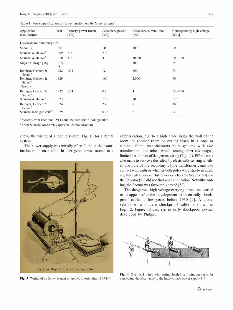
Fig. 3 Wiring of an X-ray system as applied shortly after 1895 [44]Fig. 4 Overhead wires with spring loaded self-winding reels forconnecting the X-ray tube to the high-voltage power supply [45]
Insights Imaging (2013) 4:513–523 517
Safety recommendations and regulations
Initially, little attention was paid to preventing electricalshocks from X-ray systems. Many of the first bookscontained only casual warnings against electrical shocks.However, in 1913 Albers-Schönberg warned: “Even if atthis time no injuries of patients and medical doctors havebecome known, there is no doubt that they can happen if
unfortunate circumstances coincide” [53]. With the increaseof the electrical power of the high-voltage supplies, shocksand their consequences were more severe, and electricalsafety became an issue within the professional societies. Itbecame a serious concern after the electrocution of a well-
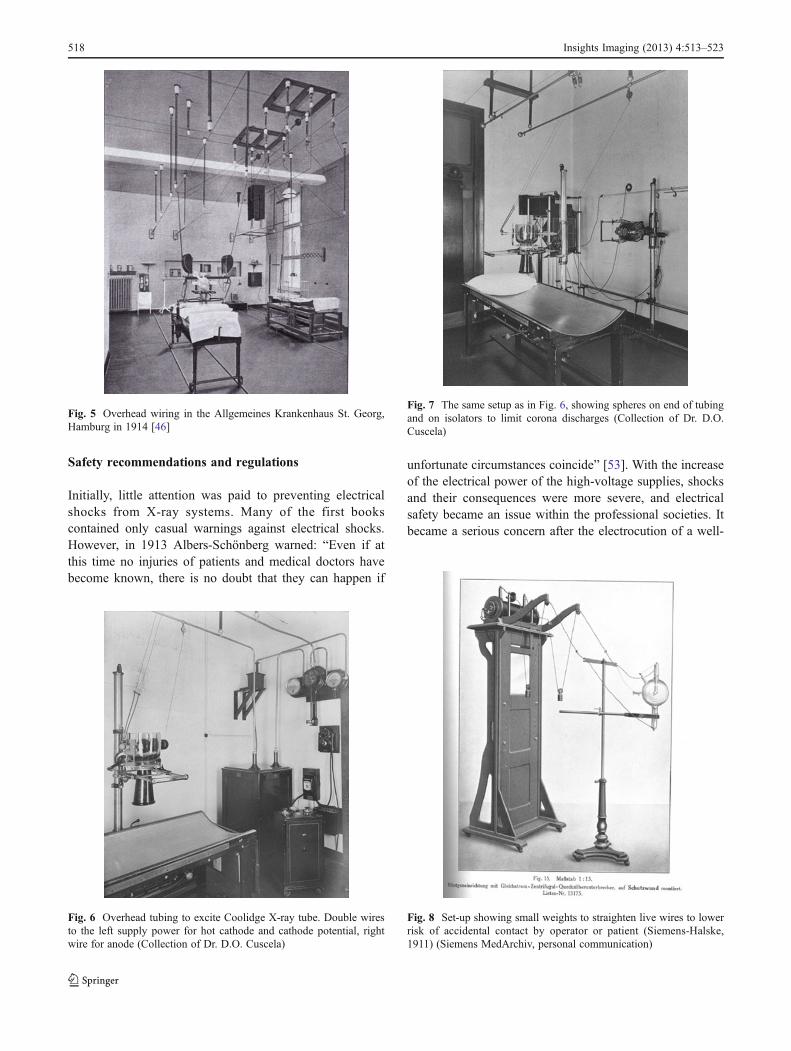
Fig. 5 Overhead wiring in the Allgemeines Krankenhaus St. Georg,Hamburg in 1914 [46]
Fig. 6 Overhead tubing to excite Coolidge X-ray tube. Double wiresto the left supply power for hot cathode and cathode potential, rightwire for anode (Collection of Dr. D.O. Cuscela)
Fig. 7 The same setup as in Fig. 6, showing spheres on end of tubingand on isolators to limit corona discharges (Collection of Dr. D.O.Cuscela)
Fig. 8 Set-up showing small weights to straighten live wires to lowerrisk of accidental contact by operator or patient (Siemens-Halske,1911) (Siemens MedArchiv, personal communication)
518 Insights Imaging (2013) 4:513–523
known and experienced French radiologist, Jaugeas [54], in1919. Electrical safety regulations were issued both in theUSA and Germany (Appendix 4) [55–57]. Between 1920and 1935, a few authors discussed aspects of electrical risks[5, 6, 38, 39], some to provide better recommendations [5, 6]
and others to show how the new regulation “DIN RÖNT I”would have affected the accidents had these rules already beenobserved [38, 39].
Victims of electrical shock
Information on electrical accidents with X-ray systems wasretrieved from newspapers in digital archives, scientificarticles, reports of legal procedures and two books [1, 58].We distinguished fatal and severe non-fatal accidents. To thelatter category we attributed accidents that were deemedimportant enough at the time to report in writing or to bethe subject of a legal procedure. Geographical coverage waslimited and determined by accessibility of sources in En-glish, German, French and Dutch. Countries for whichaccidents were found are: Australia, Austria, Denmark, Fin-land, France, Germany, Hungary, Italy, Spain, Switzerland,United Kingdom and the USA. A few articles contained
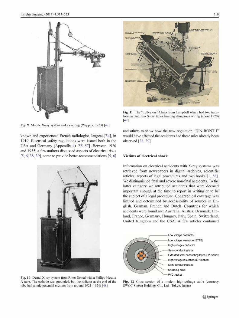
Fig. 9 Mobile X-ray system and its wiring (Wappler, 1923) [47]
Fig. 10 Dental X-ray system from Ritter Dental with a Philips MetalixA tube. The cathode was grounded, but the radiator at the end of thetube had anode potential (system from around 1921–1924) [48]
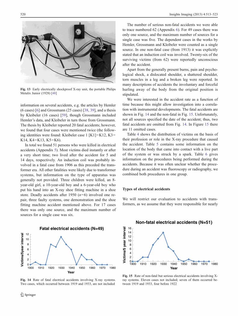
Fig. 11 The “trolleyless” Clinix from Campbell which had two trans-formers and two X-ray tubes limiting dangerous wiring (about 1920)[49]
Fig. 12 Cross-section of a modern high-voltage cable (courtesySWCC Showa Holdings Co., Ltd., Tokyo, Japan)
Insights Imaging (2013) 4:513–523 519
information on several accidents, e.g. the articles by Hemler(6 cases) [6] and Grossmann (25 cases) [38, 39], and a thesisby Kleibeler (16 cases) [59], though Grossmann includedHemler’s data, and Kleibeler in turn those from Grossmann.The thesis by Kleibeler reported 20 fatal accidents; however,we found that four cases were mentioned twice (the follow-ing identities were found: Kleibeler case 1 [K1]=K12, K3=K14, K4=K13, K5=K6).
In total we found 51 persons who were killed in electricalaccidents (Appendix 5). Most victims died instantly or aftera very short time; two lived after the accident for 5 and14 days, respectively. An induction coil was probably in-volved in a fatal case from 1906 as this preceded the trans-former era. All other fatalities were likely due to transformersystems, but information on the type of apparatus wasgenerally not provided. Three children were killed, an 8-year-old girl, a 10-year-old boy and a 6-year-old boy whoput his hand into an X-ray shoe fitting machine in a shoestore. Deadly accidents after 1950 (n=6) involved one re-pair, three faulty systems, one demonstration and the shoefitting machine accident mentioned above. For 17 casesthere was only one source, and the maximum number ofsources for a single case was six.
The number of serious non-fatal accidents we were ableto trace numbered 62 (Appendix 6). For 49 cases there wasonly one source, and the maximum number of sources for asingle case was five. The dependent cases in the works byHemler, Grossmann and Kleibeler were counted as a singlesource. In one non-fatal case (from 1913) it was explicitlystated that an induction coil was involved. Twenty-six of thesurviving victims (from 62) were reportedly unconsciousafter the accident.
Apart from the generally present burns, pain and psycho-logical shock, a dislocated shoulder, a shattered shoulder,torn muscles in a leg and a broken leg were reported. Inmany descriptions of accidents the involuntary and forcefulhurling away of the body from the original position isstipulated.
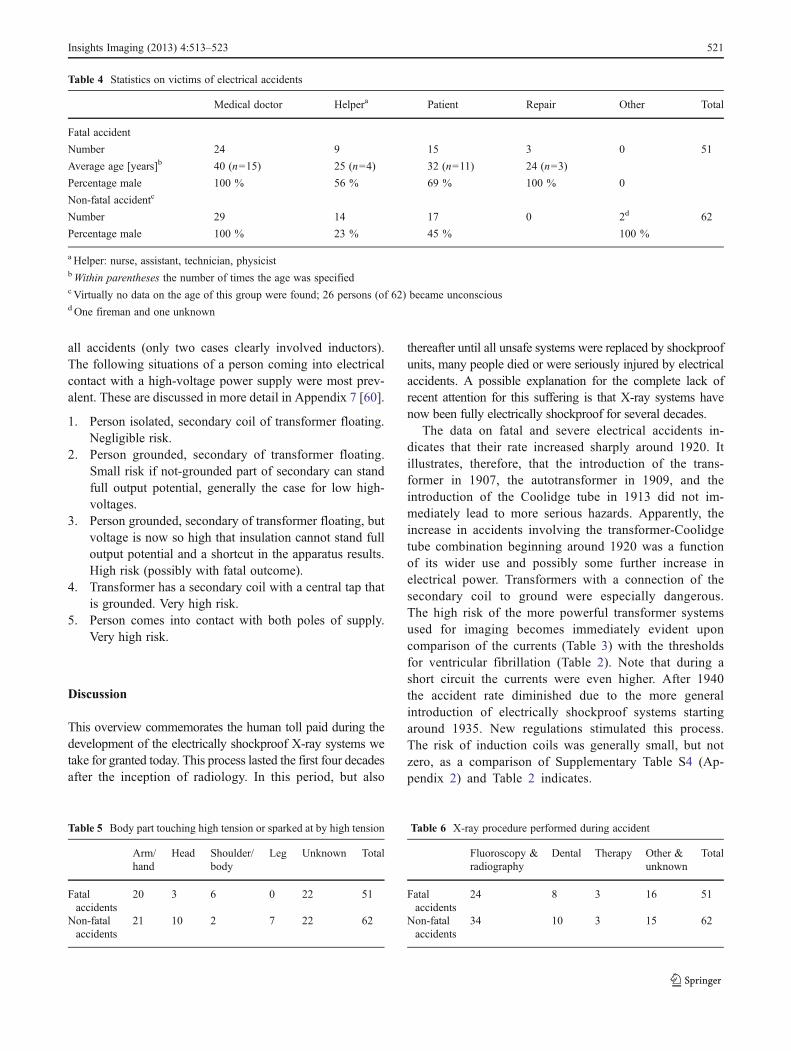
We were interested in the accident rate as a function oftime because this might allow investigation into a correla-tion with instrumental developments. The fatal accidents areshown in Fig. 14 and the non-fatal in Fig. 15. Unfortunately,not all sources specified the date of the accident; thus, twofatal accidents are omitted from Fig. 14. In Figure 15 thereare 11 omitted cases.
Table 4 shows the distribution of victims on the basis oftheir profession or role in the X-ray procedure that causedthe accident. Table 5 contains some information on thelocation of the body that came into contact with a live partof the system or was struck by a spark. Table 6 givesinformation on the procedures being performed during theaccidents. Because it was often unclear whether the proce-dure during an accident was fluoroscopy or radiography, wecombined both procedures in one group.
Types of electrical accidents
We will restrict our evaluation to accidents with trans-formers, as we assume that they were responsible for nearly
Fig. 13 Early electrically shockproof X-ray unit, the portable PhilipsMetalix Junior (1928) [48]
0
2
4
6
8
10
12
1900 1910 1920 1930 1940 1950 1960 1970 1980
Vic
tim
s/5y
ear
inte
rval
Year
Fatal electrical accidents (N=49)
Fig. 14 Rate of fatal electrical accidents involving X-ray systems.Two cases, which occurred between 1919 and 1933, are not included
02468
10121416
1900 1910 1920 1930 1940 1950 1960 1970 1980Vic
tim
s/5
year
inte
rval
Year
Non-fatal electrical accidents (N=51)
Fig. 15 Rate of non-fatal but serious electrical accidents involving X-ray systems. Eleven cases not included; seven of them occurred be-tween 1919 and 1933, four before 1922
520 Insights Imaging (2013) 4:513–523
all accidents (only two cases clearly involved inductors).The following situations of a person coming into electricalcontact with a high-voltage power supply were most prev-alent. These are discussed in more detail in Appendix 7 [60].
1. Person isolated, secondary coil of transformer floating.Negligible risk.
2. Person grounded, secondary of transformer floating.Small risk if not-grounded part of secondary can standfull output potential, generally the case for low high-voltages.
3. Person grounded, secondary of transformer floating, butvoltage is now so high that insulation cannot stand fulloutput potential and a shortcut in the apparatus results.High risk (possibly with fatal outcome).
4. Transformer has a secondary coil with a central tap thatis grounded. Very high risk.
5. Person comes into contact with both poles of supply.Very high risk.
Discussion
This overview commemorates the human toll paid during thedevelopment of the electrically shockproof X-ray systems wetake for granted today. This process lasted the first four decadesafter the inception of radiology. In this period, but also
thereafter until all unsafe systems were replaced by shockproofunits, many people died or were seriously injured by electricalaccidents. A possible explanation for the complete lack ofrecent attention for this suffering is that X-ray systems havenow been fully electrically shockproof for several decades.
The data on fatal and severe electrical accidents in-dicates that their rate increased sharply around 1920. Itillustrates, therefore, that the introduction of the trans-former in 1907, the autotransformer in 1909, and theintroduction of the Coolidge tube in 1913 did not im-mediately lead to more serious hazards. Apparently, theincrease in accidents involving the transformer-Coolidgetube combination beginning around 1920 was a functionof its wider use and possibly some further increase inelectrical power. Transformers with a connection of thesecondary coil to ground were especially dangerous.The high risk of the more powerful transformer systemsused for imaging becomes immediately evident uponcomparison of the currents (Table 3) with the thresholdsfor ventricular fibrillation (Table 2). Note that during ashort circuit the currents were even higher. After 1940the accident rate diminished due to the more generalintroduction of electrically shockproof systems startingaround 1935. New regulations stimulated this process.The risk of induction coils was generally small, but notzero, as a comparison of Supplementary Table S4 (Ap-pendix 2) and Table 2 indicates.
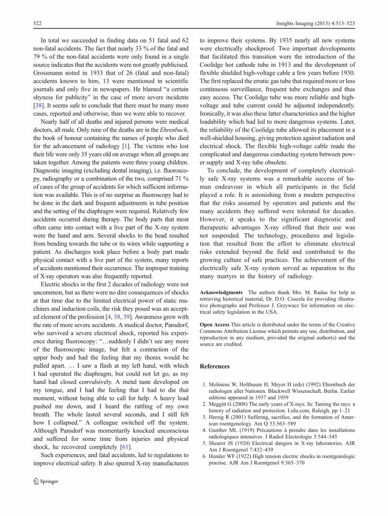
Table 4 Statistics on victims of electrical accidents
Medical doctor Helpera Patient Repair Other Total
Fatal accident
Number 24 9 15 3 0 51
Average age [years]b 40 (n=15) 25 (n=4) 32 (n=11) 24 (n=3)
Percentage male 100 % 56 % 69 % 100 % 0
Non-fatal accidentc
Number 29 14 17 0 2d 62
Percentage male 100 % 23 % 45 % 100 %
a Helper: nurse, assistant, technician, physicistbWithin parentheses the number of times the age was specifiedc Virtually no data on the age of this group were found; 26 persons (of 62) became unconsciousd One fireman and one unknown
Table 5 Body part touching high tension or sparked at by high tension
Arm/hand
Head Shoulder/body
Leg Unknown Total
Fatalaccidents
20 3 6 0 22 51
Non-fatalaccidents
21 10 2 7 22 62
Table 6 X-ray procedure performed during accident
Fluoroscopy &radiography
Dental Therapy Other &unknown
Total
Fatalaccidents
24 8 3 16 51
Non-fatalaccidents
34 10 3 15 62
Insights Imaging (2013) 4:513–523 521
In total we succeeded in finding data on 51 fatal and 62non-fatal accidents. The fact that nearly 33 % of the fatal and79 % of the non-fatal accidents were only found in a singlesource indicates that the accidents were not greatly publicised.Grossmann noted in 1933 that of 26 (fatal and non-fatal)accidents known to him, 13 were mentioned in scientificjournals and only five in newspapers. He blamed “a certainshyness for publicity” in the case of more severe incidents[38]. It seems safe to conclude that there must be many morecases, reported and otherwise, than we were able to recover.
Nearly half of all deaths and injured persons were medicaldoctors, all male. Only nine of the deaths are in the Ehrenbuch,the book of honour containing the names of people who diedfor the advancement of radiology [1]. The victims who losttheir life were only 35 years old on average when all groups aretaken together. Among the patients were three young children.Diagnostic imaging (excluding dental imaging), i.e. fluorosco-py, radiography or a combination of the two, comprised 71 %of cases of the group of accidents for which sufficient informa-tion was available. This is of no surprise as fluoroscopy had tobe done in the dark and frequent adjustments in tube positionand the setting of the diaphragm were required. Relatively fewaccidents occurred during therapy. The body parts that mostoften came into contact with a live part of the X-ray systemwere the hand and arm. Several shocks to the head resultedfrom bending towards the tube or its wires while supporting apatient. As discharges took place before a body part madephysical contact with a live part of the system, many reportsof accidents mentioned their occurrence. The improper trainingof X-ray operators was also frequently reported.
Electric shocks in the first 2 decades of radiology were notuncommon, but as there were no dire consequences of shocksat that time due to the limited electrical power of static ma-chines and induction coils, the risk they posed was an accept-ed element of the profession [4, 38, 39]. Awareness grew withthe rate of more severe accidents. A medical doctor, Pansdorf,who survived a severe electrical shock, reported his experi-ence during fluoroscopy: “…suddenly I didn’t see any moreof the fluoroscopic image, but felt a contraction of theupper body and had the feeling that my thorax would bepulled apart. … I saw a flash at my left hand, with whichI had operated the diaphragm, but could not let go, as myhand had closed convulsively. A metal taste developed onmy tongue, and I had the feeling that I had to die thatmoment, without being able to call for help. A heavy loadpushed me down, and I heard the rattling of my ownbreath. The whole lasted several seconds, and I still felthow I collapsed.” A colleague switched off the system.Although Pansdorf was momentarily knocked unconsciousand suffered for some time from injuries and physicalshock, he recovered completely [61].
Such experiences, and fatal accidents, led to regulations toimprove electrical safety. It also spurred X-ray manufacturers
to improve their systems. By 1935 nearly all new systemswere electrically shockproof. Two important developmentsthat facilitated this transition were the introduction of theCoolidge hot cathode tube in 1913 and the development offlexible shielded high-voltage cable a few years before 1930.The first replaced the erratic gas tube that requiredmore or lesscontinuous surveillance, frequent tube exchanges and thuseasy access. The Coolidge tube was more reliable and high-voltage and tube current could be adjusted independently.Ironically, it was also these latter characteristics and the higherloadability which had led to more dangerous systems. Later,the reliability of the Coolidge tube allowed its placement in awell-shielded housing, giving protection against radiation andelectrical shock. The flexible high-voltage cable made thecomplicated and dangerous conducting system between pow-er supply and X-ray tube obsolete.
To conclude, the development of completely electrical-ly safe X-ray systems was a remarkable success of hu-man endeavour in which all participants in the fieldplayed a role. It is astonishing from a modern perspectivethat the risks assumed by operators and patients and themany accidents they suffered were tolerated for decades.However, it speaks to the significant diagnostic andtherapeutic advantages X-ray offered that their use wasnot suspended. The technology, procedures and legisla-tion that resulted from the effort to eliminate electricalrisks extended beyond the field and contributed to thegrowing culture of safe practices. The achievement of theelectrically safe X-ray system served as reparation to themany martyrs in the history of radiology.
Acknowledgments The authors thank Mrs. M. Radau for help inretrieving historical material, Dr. D.O. Cuscela for providing illustra-tive photographs and Professor J. Grzywacz for information on elec-trical safety legislation in the USA.
Open Access This article is distributed under the terms of the CreativeCommons Attribution License which permits any use, distribution, andreproduction in any medium, provided the original author(s) and thesource are credited.
References
1. Molineus W, Holthusen H, Meyer H (eds) (1992) Ehrenbuch derradiologen aller Nationen. Blackwell Wissenschaft, Berlin. Earliereditions appeared in 1937 and 1959
2. Meggitt G (2008) The early years of X-rays. In: Taming the rays: ahistory of radiation and protection. Lulu.com, Raleigh, pp 1–21
3. Herzig R (2001) Suffering, sacrifice, and the formation of Amer-ican roentgenology. Am Q 53:563–589
4. Gunther ML (1919) Précautions à prendre dans les installationsradiologiques intensives. J Radiol Electrologie 3:544–545
5. Shearer JS (1920) Electrical dangers in X-ray laboratories. AJRAm J Roentgenol 7:432–439
6. Hemler WF (1922) High tension electric shocks in roentgenologicpractise. AJR Am J Roentgenol 9:365–370
522 Insights Imaging (2013) 4:513–523
7. National Electrical Code (NEC) Regulations. National Board ofFire Underwriters, New York (1931)
8. DIN RÖNT 1. Vorschriften für den Hochspannungsschutz inmedizinischen Röntgenanlagen. Deutsche Röntgen-Gesellschaft,Fachnormenausschuβ Krankenhaus, Verband DeutscherElektrotechniker E.V. (1930) Beuth, Berlin
9. Grigg ERN (1965) The trail of the invisible light. Charles CThomas, Springfield
10. International Electrotechnical Commission. Effects of current onhuman beings and livestock. Part 1. General aspects. IEC/TS60479–1. Edition 4 2005–7
11. International Electrotechnical Commission. Effects of current onhuman beings and livestock. Part 2. Special aspects. IEC/TS60479–2. Edition 3 2005–7
12. Olson W (1998) Electrical safety (Chapter 14). In: Webster JG (ed)Medical instrumentation, 3rd edn. John Wiley & Sons, New York
13. Chemical Rubber Company (1969) Spark gap voltages. In: CRChandbook of chemistry and physics, 50th edn. Chemical RubberCompany, Cleveland, p E61
14. Nisbet AT (1929) A case of burn from high-voltage current. AJRAm J Roentgenol 22:158
15. Eisenberg RL (1992) Radiology: an illustrated history. Mosby, StLouis
16. Gray J (1890) Electrical influence machines. Whittaker, London17. Graetz L (1918) Handbuch der Elektrizität und des
Magnetismus. Band I. Elektrizitätserregung und Elektrostatik.Barth, Leipzig
18. Wehrsen A (1913) Neue Starkstrommaschinen. Catalog, Berlin19. Wagner RV (1907) Catalogue of electrical instruments for physi-
cians and surgeons. Chicago20. Kassabian MK (1910) Röntgen rays and electro-therapeutics, 2nd
edn. JB Lippincott, Philadelphia21. Kaye GWC (1922) The practical applications of X-rays. Chapman
& Hall, London22. Wommelsdorf H (1912) Verbesserungen an Kondensatormaschinen.
Ann Phys 39:1201–120623. Armagnat H (1908) The theory, design and construction of induc-
tion coils. McGraw Publishing, New York24. Salomonson W (1920) Discussion on the papers by Morton, Phil-
lips and Wright. J Inst Electr Eng 58:732–73525. Morton ER (1915) A text-book of radiology. EB Treat & Co, New
York, p 11126. Morton R (1920) The efficiency of high-tension transformers as
used for X-ray purposes. J Inst Electr Eng 58:719–72627. Phillips CES (1920) Problems of interrupted and fluctuating cur-
rents. J Inst Electr Eng 58:727–72928. Crowther JA (1922) The principles of radiography. J & A Chur-
chill, London, p 10029. Donath B (1903) Die Einrichtungen zur Erzeugung der
Roentgenstrahlen, 2nd edn. Von Reuther & Reichard, Berlin30. Dessauer F, Wiesner B (1905) Kompendium der Röntgenographie.
Otto Nemnich, Leipzig31. Albers-Schönberg HE (1906) Die Röntgentechnik, 2nd edn. Lucas
Gräfe & Sillem, Hamburg32. Ruhmer EW (1904) Konstruktion, Bau und Betrieb von
Funkeninduktoren und deren Anwendung, mit besondererBerücksichtigung der Röntgenstrahlentechnik. Hachmeister &Thal, Leipzig
33. Taylor JE (1932) Induction coil—theory and applications. Pitman& Sons, London
34. Coolidge WD (1920) Oil-immersed X-ray generating outfits. AJRAm J Roentgenol 7:181–190
35. Bouwers A (1928) A new X-ray apparatus with complete X-rayand electrical protection. Acta Radiol 9:600–605
36. Meyer WM (ca. 1914–1915) Meyer interrupterless apparatus. WMMeyer, Chicago
37. Grashey G (1941) In: Grashey G (ed) RöntgendiagnostischeGeräte und Anlagen, Chapter 4, Albers-Schönberg HE—DieRöntgentechnik, vol I, 6th edn. Thieme, Leipzig
38. Grossmann G (1933) Elektrische Unfälle. Röntgen praxis 5:269–28639. Grossmann G (1933) Elektrische Unfälle (Schluβ). Röntgen praxis
5:354–36340. Green H (1910) Clover leaf tube pointers. Green & Bauer, Hartford41. General Electric Company (1924) Coolidge X-ray tube. Instruction
book 89136B. General Electric Company, Schenectady, NY, 1920.Additional information. In: Jerman C (ed) (1928) Modern X-raytechnic. Bruce Publishing, St. Paul-Minneapolis
42. Kemerink M, Dierichs TJ, Dierichs J, Huynen HJ, WildbergerJE, van Engelshoven JM, Kemerink GJ (2011) Characteristicsof a first-generation X-ray system. Radiology 259:534–539
43. Coolidge WD (1913) A powerful Röntgen ray tube with a pureelectron discharge. Phys Rev 2:409–430
44. Aubert L (1898) La photographie de l’invisible—les rayons X.Schleicher Frères, Paris
45. American X-Ray Equipment Co. Catalogue A (1915) Dental X-rayapparatus and accessories. American X-Ray Equipment Co., NewYork Chicago
46. Albers-Schönberg HE, Seeger F, Lasser I (1915) Das Röntgenhausdes Allgemeinen Krankenhauses St. Georg-Hamburg, errichtet1914/1915. Von F. Leineweber, Leipzig
47. Wappler Mobile Unit, advertisement (1923) Radiology 1:XX48. Hofman JAM (2010) The art of medical imaging. Koninklijke
Philips Electronics NV, Eindhoven49. Campbell Electric Co. (1920) Trolleyless Clinix X-ray plant. Lynn,
Mass50. Fritsch E (1928) Die Beseitigung der Hochspannungsgefahr
im Röntgenbetriebe durch den “Securo”. Strahlentherapie28:810
51. Sarsfield LGH (1934) Safety measures in X-ray work, includinghigh-voltage flexible cables. J Inst Electr Eng 75:253–270
52. Levy DM (1929) Eenige opmerkingen over de beveiliging tegenhoogspanningsgevaar in het röntgenlaboratorium. Ned TijdschrGeneeskd 73:3206–3211
53. Albers-Schönberg HE (1913) Die Röntgentechnik, 4th edn. LucasGräfe & Sillem, Hamburg
54. Case JT (1921) Death of Dr. F. Jaugeas. AJR Am J Roentgenol7:167–168
55. Christie AC (1921) New committees. AJR Am J Roentgenol 8:20456. Imboden HM (1923) Report of the safety committee presented at
the Los Angeles Meeting of the A.R.R.S. Am J Roentgenol Radi-um Ther 10:246–247
57. Warnshuis FC (1936) Concerning an imaginary law demandingshockproof X-ray rooms. Cal West Med 44:136
58. Jellinek S (1931) Der elektrische Unfall, 3rd edn. Franz Deuticke,Leipzig
59. Kleibeler B (1965) Tödliche Hochspannungsunfälle beimUmgang mit Röntgenapparaten für medizinische Zwecke,Inaugural-Dissertation an der Medizinischen Fakultät derFreien Universität, Berlin
60. Wetterstrand GA (1925) A roentgen accident with a fatal resultthrough the short-circuiting of the secondary current. Acta Radiol5:105–108
61. Pansdorf H (1930) Starkstrom- und Hochspannungsschäden imRöntgenbetriebe. Roentgenpraxis 2:359–366
Insights Imaging (2013) 4:513–523 523