Embed Size (px)
Citation preview

Transmitted by the expert from the NetherlandsInformal document GRB-68-10(68th GRB, 12-14 September 2018,agenda item 16)
Draft measurement methods for piek noise during loading and unloading (2018 update)
Date July 2018Number of pages 70 (incl. appendices) Number of appendices 1
Stichting Piek-Keur Postbus 74800 1070 DM Amsterdam Tel. (+31) 020-5044949 Fax (+31) 020-6463857 [email protected]
All rights reserved. No part of this report may be reproduced and/or published by means of printing, photocopying, microfilm or by any other means without prior written permission from Piek-Keur.© 2018 Piek-Keur
1Draft

Foreword
These are the concept 2018 Piek-Keur measurement methods for peak noise during loading and unloading, published by Stichting Piek-Keur. These measurement methods are an update to the ‘Methods of measurement for peak noise during loading and unloading’ of 2015 [8]. The measurement methods must be agreed by the Piek-Keur panel of experts.
These measurement methods are intended for everyone involved in producing and marketing new equipment and materials used in loading and unloading goods in the retail trade. In the future, the methodology may be able to be adapted for use in other fields like package delivery, quiet truck parkings etc.
A measurement and report in accordance with the 2018 Piek-Keur methods of measurement for peak noise during loading and unloading make it possible for participants of Stichting Piek-Keur to have their component certified under Piek-Keur.
Changes to this version:Substantial changes to the protocol were made in 2018. These changes can be found in Chapters 1, 2, 3 and 4 amongst others. Parts of the text have been updated, elucidated and amended in order to reflect current understandings and standards. Part of the existing text has been moved and the order has been changed.
- The method’s background has been clustered in Chapter 1 and a new Section with definitions has been added. These definitions are primarily based on the methods of measurement for QuietTrucks (chapter 4). Future updates to the protocol may be necessary if other products need to be added to the Section with definitions.
- The requirements for product certification have been clustered in Chapter 2 together with a more detailed description of the requirements for product conformity.
- Chapter 3 gives the general requirements for the measurements. The requirements have been upgraded and amended to reflect the latest (ISO and IEC) standards
- The methods of measurement for the QuietTruck dealt with in Chapter 4 are now more in line with international type approval requirements for vehicles in accordance with UNECE Regulation R51. A number of measurements included in the 2015 version have been replaced with measurements from R51. Chapter 4 may be further adapted to reflect UNECE Regulations in the future. However, this depends on developments in UNECE GRBP. A number of “informative” measurements have been included in Chapter 4 in anticipation of these developments. These need to be executed and reported but the limit values do not need to be matched.
Chapters 5 up to and including 11 have barely changed.- A small change has been made to Section 5.1 to help clarify the measurement distance.- The Section which was part of Chapter 11 which related to product requirements using
multiple methods of measurement has been moved to Chapter 2.The data which needs to be recorded for QuietTruck which was included in Chapter 11 has been amended.
2Draft

Summary This document describes the methods of measurement that are suitable for determining the peak noise levels of various noise sources during loading and unloading. The methods of measurement provide peak noise levels for single sources under controlled conditions at a distance of 7.5 metres from the source.
The methods of measurement are set up to yield both representative and reproducible results, which approach the practical conditions as closely as possible. The methods are set up in such a way that noise-reducing measures are clearly expressed in the measurement results.
The measured peak levels can be used to obtain an indication of whether the product in question will meet the legal limit values in most practical situations. Furthermore, the methods of measurement are used to compare the peak noise emissions of products with each other.
The methods include: Rolling noise of van and lorry. Doors, hatches, hinged and roller doors of cargo bodies and sliding
partitions, steps and strip curtains Tailboards, floors and walls of cargo body in commercial vehicles and lashing devices Shopping trolleys, roll containers, rollies, dollies and pallet trucks (Mobile) forklift trucks Transport refrigeration
3Draft

Table of contents
ContentsForeword............................................................................................................................................2
Summary............................................................................................................................................4
Table of contents................................................................................................................................5
1. Introduction...................................................................................................................................9
1.1. Objective, background and scope of the methods of measurement.......................................9
1.2 Directionality..........................................................................................................................10
1.3 PEAK mode.............................................................................................................................10
1.4 Definitions..............................................................................................................................11
2. Product certification requirements..............................................................................................12
2.1 Limits per product..................................................................................................................12
2.2 Mandatory methods of measurement per product................................................................12
2.3. Product family, worst-case scenario and representative samples.........................................13
2.4. Product conformity (PC)........................................................................................................14
2.5. Continuing conformity during the product’s use phase........................................................15
2.6. Procedure for applying for certification.................................................................................15
2.7. Transitional provisions...........................................................................................................15
3. Measuring equipment, general measuring conditions and procedure.........................................16
3.1 Measuring equipment............................................................................................................16
3.2 Measuring conditions.............................................................................................................16
3.3 Measurements.......................................................................................................................18
4. Method of measurement for pass by noise of vans and lorries, and alarm systems....................20
4.1 Measuring course, measuring conditions...............................................................................20
4.2 Accelerating............................................................................................................................21
4.3 Compressed air noise.............................................................................................................22
4.4 Reversing alarm system and blind spot warning....................................................................23
4.5 Pass by noise..........................................................................................................................24
5. Method of measurement for opening and closing doors of loading areas and cabins and air curtains for cargo bodies and sliding partitions, steps and strip curtains.........................................25
5.1 Vehicle doors, hatches, hinged and roller doors and air curtains of cargo bodies.................25
5.2 Roller doors and sliding panels...............................................................................................26
5.3 Sliding partition......................................................................................................................27
4Draft

5.4 Steps.......................................................................................................................................28
5.5 Strip curtain............................................................................................................................28
6. Methods of measurement for the tailboard and walls of commercial vehicles and lashing devices.........................................................................................................................................................30
6.1 Measuring arrangement.........................................................................................................30
6.2 Tailboard................................................................................................................................30
6.3 Rolling noise...........................................................................................................................31
6.4 Noise of collision with walls of the cargo body.......................................................................33
6.5 Load fastening system............................................................................................................35
7. Method of measurement for shopping trolleys and pallet trucks................................................36
7.1 Rolling noise...........................................................................................................................36
8. Method of measurement for roll containers, rollies and dollies..................................................38
8.1 Rolling noise...........................................................................................................................38
8.2 Colliding/nesting roll containers.............................................................................................38
8.3 Placing and removing additional loading shelves...................................................................39
8.4 Stacking rollies and dollies......................................................................................................39
9. Method of measurement for forklift trucks and mobile forklift trucks.........................................40
9.1 Driving....................................................................................................................................40
9.2 Evaluation of lifting.................................................................................................................40
9.3 Evaluation of connecting mobile forklift truck........................................................................40
10. Method of measurement for transport refrigeration.................................................................42
10.1 Types of transport refrigeration...........................................................................................42
10.2 Measuring arrangements.....................................................................................................43
10.3 Measurement procedures....................................................................................................45
10.4 Refrigeration system with PEAK mode.................................................................................49
11. Reporting....................................................................................................................................50
12. References..................................................................................................................................67
13. Signatures...................................................................................................................................68
Annex A NOVEM memo, 4 July 2002....................................................................................................69
5Draft

1. Introduction
The 2018 Piek-Keur test protocol complies with the Decree on Environmental Management in Craft and Retail Trades (the Decree), which was incorporated in the Decree on General Rules for Environmental Management in 1998.This report describes methods of measurement that are suitable for determining the peak noise levels of relevant sources of noise during loading and unloading. The measurement methods determine peak noise levels for single sources under controlled conditions at a distance of 7.5 metres from the source. The measurement methods are set up to yield both representative and reproducible results, which approach the practical conditions as closely as possible. Furthermore, the methods of measurement are set up in such a way that the noise-reducing measures are clearly expressed in the measurement results.
Technology develops at lightning speed; Piek-Keur is no exception to this. This protocol incorporates the relevant innovations. Furthermore, the experiences of the past twenty years regarding Piek-Keur were incorporated in the 2018 Piek-Keur test protocol.
In addition, a clear structure was chosen, with a subdivision into the following subjects:- requirements to products, measuring conditions and measuring equipment (chapter 2),- methods of measurement (chapters 3 up to and including 10),- and the reports (chapter 11)
This subdivision improves the protocol's accessibility for certification.The protocol was extensively discussed with our partners. A large number of our partners provided their expertise free of charge, and we thank them for this.The result of all the efforts is an up-to-date and accessible protocol, safeguarding the validity and
reliability of the measurement results as much as possible.
1.1. Objective, background and scope of the methods of measurement The methods of measurement described in this document are used for determining the peak noise levels of various noise sources during loading and unloading. The measurement methods provide peak noise levels for single sources under controlled conditions at a distance of 7.5 metres from the source. Dutch law on peak noise during loading and unloading (the Decree) applies to the peak noise level at the outer wall in practical conditions. The measured peak levels can be used to obtain an indication of whether the product in question will meet the legal limit values in most practical situations. It may be, however, that a product complies with the limit value at 7.5 metres, but that the distance from the source to the outer wall is less in a particular practical situation, so that it does not comply with the legal limit value in that specific situation. Furthermore, the methods of measurement are used to compare the peak noise emissions of products with each other.
6Draft

The methods of measurement are intended to evaluate partial sources in their practical conditions, where there is interaction with other components. In cases where artificial collision is used, this is done to ensure that the measurements are reproducible. The methods are not suitable for determining the noise capacity level.
1.2 Directionality Many noise sources have directional noise radiation, which means that noise levels vary depending on the direction from which noise radiates. As noise can be observed in all possible directions in terms of the noise source in inner-city situations (both around and above the noise source), the measured level should be the maximum noise level from all possible radiation directions. This type of measurement may require disproportionate measurement efforts in practice, especially in the case of highly variable noises. For practical reasons, the aim therefore was to prescribe as few measuring points as possible. The radiation directions that are expected to be most critical, however, were taken into account. For some noise sources, such as moving vehicles, it is difficult to measure in all radiation directions. Here it was decided, in accordance with international rules, to measure to the left and right of the vehicle only. Conversely, the method of measurement must not result in noise-limiting measures being designed so that the maximum effects are achieved only in the direction of the measuring points indicated in this report. A good example of less than optimal design (for inner-city use) is transport refrigeration systems installed at the front end of a cargo body. The insulating enclosure is often designed in such a way that an effect is achieved horizontally, but little effect upwards. The top of the enclosure is usually left open.
1.3 PEAK modeFor various parts/machines present on a vehicle, the speed of functioning may affect the noise level produced by the part. Examples of this are the RPM of a refrigeration unit's motor or a lorry's engine. If the part has two speeds and the part/machine is tested at the low speed setting, this is called “PEAK mode”.
If a part or machine has a PEAK mode it should activate automatically and should not function dependent on the actions of the driver. PEAK mode must ensure that the part/machine meets the PEAK noise requirements within a distance of 300 metres from the loading/unloading location.
The basic principle of a PEAK mode is that it is driver-independent and that, outside of the PEAK-specified time frames and outside of the so-called PEAK locations, the machine can be set to maximum power with technical tools. In other words, PEAK mode is the normal operating setting of the machine. In case of a defect in the technical tool or other faults relating to the functioning of PEAK mode, the part/machine must operate in PEAK mode. The functioning of PEAK mode must be guaranteed. The functioning of PEAK mode must also be demonstrated and described in the report.
The above listed demands do not apply to drive by noise of vans and lorries (in accordance with Chapter 4). The PEAK mode may be operated manually and does not need to be driver-independent.
7Draft

Vans and lorries which require driver intervention to switch on the PEAK mode should switch this function on as soon as they enter a zone of 300 metres surrounding the loading/unloading location.
1.4 Definitions n,rated: The highest engine speed at which 90% of the maximum power output is still achieved. n,max: The highest engine speed which can be achieved without engine load. nmax reduced: The maximum idling speed in the event that a reduced PEAK mode in engine
management has been activated. Pn: The maximum vehicle power output in its normal state without any possible limitations
resulting from PEAK mode. mtest: The total mass of the vehicle which is being tested including the driver, measurement
equipment etc. PEAK mode: A deliberately changed operating condition in a product with the goal of
temporarily reducing noise production.
Vehicle category (in accordance with UNECE RE3 [4]):N: motor vehicle with a least 4 wheels intended for the transportation of goods
N1: ... with a maximum mass of no more than 3.5 tonnes N2: ... with a maximum mass of more than 3.5 tonnes but not more than 12 tonnes N3: ... with a maximum mass of more than 12 tonnes
8Draft

2. Product certification requirements
2.1 Limits per productThe noise level of the product being certified may, in accordance with the protocol described below, never exceed the following limit values:
Limit (dB(A))QuietTruck 72Other products 60* These are the limits for Stichting Piek-Keur Certification. Other bodies may apply different limit values (e.g. for subsidy purposes).
2.2 Mandatory measurement methods per productChapters 4 up to and including 10 describe the measurement methods for the various products. One or more measurement methods may need to be executed during the certification process depending on the type of product. Multiple measurement methods need to be executed in accordance with the list below for the following products. All measurements need to meet the limit values included in 2.1, unless explicitly stated otherwise. The final result per product is the highest value of the methods of measurement listed
2.2.1 QuietTruckThe following measurements need to be carried out when certifying a QuietTruck:
- The following values need to be measured and reported and they need to meet the limit values included in paragraph 2.1 (normative)
o Paragraph 4.2 Accelerating 0-20 kpho Paragraph 4.3 Compressed air noise (measured in conformity with ECE R51.03 Annex
5)o Paragraph 4.4 Reversing alarm system and/or blind spot alarm
- The following values need to be measured and reported but they do not need to meet the limit values included in paragraph 2.1 (informative)
o Paragraph 4.5 The pass by noise (measured in conformity with ECE R51.03 Annex 3)o Paragraph 5.1 Cabin doors
Remarks relating to the use of ECE R51 for the certification of a QuietTruck:- In contrast to any passages in ECE R51 relating to permissible noise levels or limit values; all
PEAK noise measurements are subject to the PEAK limits included in Section 2.1 and 2.2.1
2.2.2 TailboardTo certify a tailboard, it must pass the following measurements:
- 6.2.1 Opening and closing- 6.2.2 Roll-off stop
9Draft

- 6.3.1 Rolling over the tailboard- 6.3.3 Rolling over transitions
2.2.3 Pallet truckTo certify a pallet truck, it must pass the following measurements:
- 7.1 Rolling noise- 7.3 Lowering and raising
2.2.4 Roll containerTo certify a roll container, it must pass the following measurements:
- 8.1.1 Loaded- 8.1.2 Rolling nested roll containers or- 8.1.3 Rolling empty roll containers that cannot be nested- 8.2 Colliding/nesting roll containers- 8.3 Placing and removing additional loading shelves
2.2.5 Rolly or dollyTo certify a rolly or dolly, it must pass the following measurements:
- 8.1.1 Loaded- 8.1.4 Rolling stacked rollies and dollies- 8.4 Stacking rollies and dollies
2.2.6 Forklift truckTo certify a forklift truck, it must pass the following measurements:
- 9.1 Driving- 9.2 Evaluation of lifting
2.2.7 Mobile forklift truckTo certify a mobile forklift truck, it must pass the following measurements:
- 9.1 Driving- 9.2 Evaluation of lifting- 9.3 Evaluation of connecting mobile forklift truck
2.3. Product family, worst-case scenario and representative samples In principle, PEAK certificates are issued for a single product or for a series of identical products. To certify a series of identical products, PEAK noise measurements need to be carried out on a (random) sample from that series.
In analogy with vehicle type approval, permission will be granted for the use of product families upon request from the manufacturer. The most important noise sources (like the engine) are identical within a family. The parts or characteristics which are less important to noise production may differ
10Draft

within a family. However, PEAK noise measurements need to be carried out under “worst-case scenario” conditions for the product family in question. In other words, the product within a family which is expected to produce the most noise needs to be tested. In some cases permission will be granted to demonstrate the worst-case scenario using the measurement results gained during the vehicle type approval.
Determining the worst-case scenario for QuietTrucks (Chapter 4) will take place in line with the vehicle type approval as set down in ECE R51. The following requirements are applicable to determine the worst-case scenario for QuietTrucks:
Vehicle component Worst-case scenario for PEAK soundEngine Engine from a family with the highest power
outputCabin Shortest cabinWheelbase Shortest wheelbaseExhaust The position of the opening (left, right, low, high)
and the order of pipes and dampers is relevant. The worst-case scenario needs to be demonstrated using data from the vehicle type approval or by carrying out multiple PEAK measurements
Rear axle * The highest reductionGearbox * The highest reduction while in first gearTyres * Tyre with the smallest diameter(Side) skirts, covers, underrun protection** As small and as bare as possible, with minimal
acoustic absorption and/or shieldingVehicle body** As small and as bare as possible, with minimal
acoustic absorption and/or shielding* In practice, the worst-case scenario is determined by combining these three items. Together they help determine
the total final reduction. The worst-case scenario is the version with the highest practical and deliverable total final reduction; one which results in the lowest possible vehicle speed for a particular engine speed.
** A vehicle which has been fitted with a side cover or body etc. will be deemed to be representative of the whole vehicle family. It will be assumed that all vehicles within that family have been equipped with the same side cover or body etc., or with a side cover or body which offers the same acoustic reduction.
***Measurements should be used to prove which variant offers the worst-case scenario if vehicles within a product family fall into different vehicle categories (like N1 and N2)
We recommend the manufacturer contact Stichting Piek-Keur in advance for advice about the worst-case scenario. PEAK noise measurements carried out for a vehicle which is not the theoretical worst-case scenario within a Product Family will result in the allocation of a de facto upper limit for vehicles within that Product Family. Other products which are assumed to be noisier following an analysis of the criteria featured in the table will not be considered part of the Product Family.
2.4. Product conformity (PC) PEAK certificates are issued for a series of identical products or for a family of acoustically comparable products. The noise requirements are applicable to both the representative sample and
11Draft

to the other products in that series which are produced by the manufacturer. The manufacturer or the participant affiliated with Stichting Piek-Keur will do everything within its power to ensure that manufactured products meet the noise standards featured in the PEAK protocol. Stichting Piek-Keur may execute spot checks to help verify this.Failing a noise value spot check by more than 1 dB(A) may result in a second and third spot check being carried out. Stichting Piek-Keur retains the right to withdraw PEAK certification until a manufacturer can prove that their products are in conformity with PEAK demands if more than one noise value spot check is failed by more than 1 dB(A).
2.5. Continuing conformity during the product’s use phaseDuring the design and production phase, the manufacturer will do everything within their power to ensure that the product’s noise emissions, during normal usage, will in the long run continue to meet the requirements in the PEAK protocol. This includes, but is not limited to, preventing corrosion, the sustainable mounting of noise reducing measures and the prevention of wear and tear.
2.6. Procedure for applying for certificationWhen applying for a PEAK certificate and the right to apply PEAK stickers to their product, the manufacturer or importer will be asked to sign a declaration.
- With every individual sticker request in the System, the manufacturer needs to refer to the initial Product Family report which they believe is applicable to the individual vehicle body in question.
- By referring to a particular report the manufacturer believes that the product in question meets the characteristics included in that report;
- Additionally, the manufacturer also states - by means of selecting the disclaimer for the product in question - that the product being entered into the System as part of the administrative process for allocating a sticker also meets the characteristics in that report to the maximum extent possible. The manufacturer accepts all possible (financial) consequences and indemnifies the Stichting for all liabilities resulting from any party if it becomes apparent that this is not the case;
- Furthermore, the Stichting should also be provided with the opportunity to carry out spot checks and the manufacturer accepts the risk that failing this type of test may result in a fine or in other appropriate measures such as: a warning, a temporary suspension of the certification’s validity for a Product Family or the permanent withdrawal of certification.
2.7. Transitional provisionsAs of 1 January 2019, Stichting Piek-Keur will not issue PEAK certificates if the noise measurements and additional documents do not meet the demands in the test protocol entitled “Measurement methods for piek noise during loading and unloading (2018 update).
12Draft

3. Measuring equipment, general measuring conditions and procedure The requirements made on the equipment, acoustic environment, meteorological conditions and background level mostly reflect those included in ECE regulation R51 Annex 3 [3]. The following deviations and additions apply:
3.1 Measuring equipment The following equipment is required to measure peak levels: Sound level meter, type 1 (in conformity with “IEC 61672-1:2013: Sound Level Meters”, equipped
with an A filter, “Fast” adjustable integration time and read-out option set to “Max. Hold” or an equivalent data acquisition system (to be proven using certificates)
Windshield for microphone Acoustic source type 1 (in accordance with IEC 60942:2017, Sound calibrator) to calibrate the
sound level meter Speedometer, accuracy +/- 1 kph Revolution counter, accuracy +/- 3%The sound level meter and the acoustic source must be calibrated by a certified institution at least once every two years. The necessary certificates for the measuring equipment used should be submitted to Stichting Piek-Keur upon request.
3.2 Measuring conditions During measuring, the background noise level (LpA) should be at least 10 dB(A) lower than the noise level produced by the source/activity being assessed. Ideally, the background noise level in area should be lower than 45 dB(A). The background noise level is the maximum noise level LA,max resulting from external sources during the execution of a PEAK noise measurement. The amount of background noise level can be determined by measuring the maximum noise level LA,max resulting from external sources, for a period of 1 minute. This value should be recorded. No corrections are to be carried out due to eventual contributions from background noise.The current wind speed (at the measurement height) may not exceed 5 m/s. Noise measurements should be carried out when it is dry.The air temperature should be between 5 and 35oC.
There should not be any reflecting outer walls or objects within a radius of 25m from the object to be measured or the microphone(s). There should not be any objects or people between the target object and the microphone.
Ideally, measurements should be executed in a testing area and on a surface which meets the requirements in ISO 10844:2014. However, to ensure that the methods of measurement remain accessible to smaller manufacturers, acoustically comparable testing areas may be used, like a car park, as long as they meet the following qualifications:
- This testing area is large enough to accommodate the prescribed actions and/or movements the target object needs to perform as well as being large enough to accommodate microphones at the prescribed distance.
13Draft

- The surface under the microphone, under the target object, between the (moving) target objects and microphone, as well as within a radius of at least 1 metre surrounding that area should be smooth and ‘acoustically’ hard (see figure 3.1). ‘Acoustically hard’ is understood to mean a surface with an absorption coefficient of ≤ 10% in the frequency range of 315 up to and including 1600 Hz. A closed surface consisting of dense concrete, dense clinkers or dense asphalt concrete are considered sufficient. Other surfaces like porous road surfaces (pervious concrete), gravel, sand or (planted) ground are considered insufficient. If there are any doubts, the manufacturer is obliged to prove that the surface meets the demands listed above by means of additional measurements demonstrating the absorption coefficient.
The surface under the target object, under the microphone and between the target object and the microphone should be clean and dry and free of any snow, ice, leaves, grass, sand or noise scattering and/or noise absorbing substances.
Figure 3.1: Minimum dimensions for the acoustically hard surface (e.g. to determine the pass by noise of vehicles in accordance with Chapter 4).
Deviations can be made from the measurement conditions described. However, this is only permitted if it leads to higher noise levels. Some examples are:
- obstacles behind the noise source or sound level meter if these obstacles are nearer to these items than prescribed
- higher levels of background noise than permitted - measurements are carried out indoors instead of outdoors- a wet surface or a surface with a rougher finish
Deviations which may result in lower noise levels are not permitted. Examples include:- Obstacles located between the noise source and the sound level meter- Absorbent surfaces like pervious asphalt or gravel- A surface covered in snow, leaves etc.
All deviations from the prescribed measurement conditions should be accurately recorded and images should be included in the report.
14Draft
Microphone
Road axis
7.5m

3.3 Measurements For stationary tests, the microphone is aimed at the measured object, parallel to the ground. For moving objects, the microphone is also directed perpendicular to the direction of movement. The standard measuring distance for moving test objects is 7.5m from the driving line, and for stationary set-ups 7.5m from the axis of the object to be measured, on the side of the noise source. A stationary set-up at 7.5m from the edge of the target object is required for ‘some’ measurements. The standard microphone height is between 1.2m ± 0.02m above the road surface.
All measurements (measurement distances, courses etc.) which are listed in the test protocol are subject to a standard tolerance of 1% unless otherwise stated. All target speeds are subject to a standard tolerance of 10% with a minimum of 1 kph unless stated otherwise.Measurements outside the tolerance area or measurements with unexpected, non-representative noise peaks must be discounted. Complete working cycles are always measured at least 3 times.
In general, measurements will be taken in an unloaded condition, unless the paragraphs in question demand a loaded condition. Readings of non-representative, interrupted or erroneous measurements must be removed. If only one microphone (sound level meter) is available, the prescribed number of actions will have to be carried out for each measuring point. A reading of the A-weighted maximum noise level (LA,max) will be recorded during the prescribed working cycle with the settings - ‘Fast’ and ‘Max hold’ activated - using a sound level meter.
The following sections indicate how the noise level is specified for each type of source.In some cases, the highest value of multiple readings will be determined and arithmetically rounded to a whole number in dB(A), see table 3.1.
Table 3.1: Example of highest value reading rounded to a whole number
In other test set-ups, an energetic average noise level will be determined for a number of LA,max values. The energetic average of a series of n measured values L1, L2, L3,….Ln is defined in accordance with:
For energetic averaging over multiple measurements, only the average value is arithmetically rounded to a whole number in dB(A), see table 3.2. Table 3.2: Example of energetic averaging with rounding to a whole number.
15Draft
1st reading2nd reading 3rd reading 4th reading Highest value
86.3 87.6 86.8 84.5 88

The number of averages varies depending on the type of measurement. The number of averages may be increased, which may result in a more stable average value. The recorded results are read off and presented with one decimal place. The mathematical results are presented with one decimal place. The evaluation result is then presented in whole dB. Rounding to the nearest whole number is done arithmetically. This means that, if the number to be rounded ends in 5 after the decimal point, it is rounded to the higher nearest whole number. For example, 40.5 is rounded to 41.
16Draft
1st reading 2nd reading 3rd reading 4th reading Energetic average value86.3 87.4 86.8 84.5 86

4. Method of measurement for pass by noise of vans and lorries, and alarm systems
4.1 Measuring course, measuring conditions The measuring course must be part of a straight section of road approx. 100m long. A microphone is placed halfway along the measuring course at 7.5m ± 0.075m in line CC’ with the microphone (see Figure 4.1). The noise measurements can be done with a single microphone (sound level meter), in which case the measuring course must be driven from right to left and from left to right to measure both sides of the vehicle. One direction is deemed sufficient if two microphones (sound level meters) are available. However, one microphone can be moved back and forth depending on local traffic situations or the manufacturer’s preferences.
At least three measurements are taken on both sides of the vehicle.
The following measuring conditions apply to the vehicle: The vehicle to be measured must be in normal, ready to use condition Vehicles which have multiple modes (sport, eco, winter, off-road, etc.) should activate the
standard mode used for driving on public roads If the vehicle is equipped with a PEAK mode function, the tests can be performed with PEAK mode
activated. This is on the condition that the driver has access to the PEAK mode switch inside the cabin or if PEAK mode is automatically activated by the vehicle itself.
Load during noise measurements: N2 and N3 vehicle category lorries (> 3,500 kg) should carry a load consisting of a test mass
for the vehicle mtest = 50 [kg/kW] x Pn [kW] where Pn equals the vehicle’s maximum power output in an unlimited condition. However, the test mass is limited to the maximum permissible vehicle weight.
N1 vehicle category vans (≤ 3,500 kg) should carry a load consisting of test mass mtest of the empty weight plus 50% of the loading capacity.
The test mass is measured with the vehicle in running order. This means it incudes the measuring equipment, driver, fuel and any additional load etc. The measured test mass must be reported in the test report.
The tolerance for the prescribed test mass is +/- 5%. The prescribed load may be placed in or on top of the towing vehicle. The added weight may
not affect the character of the powertrain noise resulting from the vehicle, i.e. it may not be equipped with noise absorbent and/or noise blocking surfaces. These constructions may not contribute to the noise produced in any significant way, e.g. the vehicle should not contain any loose, rattling items.
The use of a construction, articulated element or a trailer for transporting the load is not permitted unless this type of construction is standard for the vehicle and is covered by the “worst-case scenario” definition which has been described in Section 2.3
Given the low speed during testing, tyre noise falls outside the scope of this test. The brand and type of tyres used is, as a result, at the manufacturer’s discretion. Please note that the tyres must
17Draft

meet the legal requirements for use on public roads. For a low and reproducible noise level during the test, it may be important to avoid traction tyres, winter tyres or other tyres with a coarse tyre profile. The size of the tyre is part of the worst-case scenario description found in Section 2.3.
4.2 Accelerating The following procedure must be completed (see Figure 4.1):
The 1st series of measurements (for all vehicles): accelerating and changing gears if necessary The length of the measuring course is 20m (10m before and 10m after the microphone). The loaded vehicle at the beginning of the measurement is standing still and is located at the start
of the course (before line AA’) and is ready to accelerate. This means for example (if applicable):o With idling engineo PEAK mode has been activatedo The brakes are on if necessaryo Vehicles with a manual gearbox should be in first gear with the engine disengaged.
First gear is understood to mean the lowest possible gear ratio suitable for moving forwards on a flat public road while taking the vehicle’s test mass into account. Special low gears for the use in terrain, manoeuvring or crawling up hill etc. should not be used (please consult the manufacturer’s user manual for further information about normal usage).
o Vehicles with an automatic transmission should be placed in the standard mode for driving forward and automatic shifting (D/Drive)
The vehicle should then accelerate as quickly as possible, at full throttle, from a stationary position.
Acceleration will continue until one of the following situations occurs: o A speed of 20 kph is reachedo The rear of the vehicle reaches the end of the course at line BB’
At that moment, the accelerator is released, the measurement is stopped and the noise levels are read.
On the measuring course, gears may need to be shiftedo Vehicles with an automatic gearbox will shift automatically and the moment to shift
gear, if relevant, may be supported by a PEAK modeo Vehicles with manual transmission require the driver to change gears as quickly as
possible to the next higher gear, as soon as: the RPM A x n,rated , is reached. Factor A equals
A= 0.72 ± 0.02 for category N1 and N2 vehicles A= 0.87 ± 0.02 for category N3 vehicles
the RPM nmax reduced is achieved (if the test is being carried out in PEAK mode).After shifting gear, the driver again goes full throttle as quickly as possible to accelerate as much as possible. This procedure for accelerating and shifting gears may need to be repeated a number of times until the vehicle has reached the end of the course or achieves a speed of 20 kph.
18Draft

Figure 4.1: Measuring course for the acceleration test.
2nd series of measurements: accelerating without shifting gears (only applicable to vehicles with manual transmission) The length of the measuring course is 20m (line AA’ is located 10m before the microphone line
and line BB’ is located 10m past the microphone line). The loaded vehicle should drive along the driving line (line CC’) in first gear with an idle speed
setting. First gear is understood to mean the lowest possible gear ratio suitable for moving forwards on a flat public road while taking the vehicle’s test mass into account. Special low gears for the use in terrain, manoeuvring or crawling up hill etc. should not be used (please consult the manufacturer’s user manual for further information about normal usage).
The accelerator is pressed down as hard as possible when the start of the measuring course (line AA’) is reached.
The accelerator is kept down until the rear of the vehicle reaches the end of the course and crosses line BB’. The accelerator is then released, the measurement is stopped and the measurement values are read
The measurement result is determined as follows: The highest value from both measuring points of the 1st series of measurements is taken. The highest value from both measuring points of the 2nd series of measurements is taken. The highest value for the two runs is rounded to a whole number in accordance with Section 3.3. This is the measurement result.
4.3 Compressed air noise The compressed air noise for the following sources is measured in accordance with the procedures described in ECE R51.03 Annex 5 [3]
Pressurising the compressor and blowing off the pressure regulator Blowing off or decompressing the foot brake Blowing off or decompressing the hand brake.
At least three measurements of each of the three above-mentioned blow off events are made.
19Draft
Start accelerating
Microphone
Driving line
7.5m

The measurement result is determined as follows: The highest value from both measuring points of the 3 series of measurements is taken. The maximum of these two values is rounded to a whole number in accordance with Section 3.3. This is the measurement result.
4.4 Reversing alarm system and blind spot warning The measurement is only carried out if the system can be used when manoeuvring during loading and unloading. If applicable, the measurement will be carried out in PEAK mode, which automatically reduces the volume emitted by the warning signal. If the system is not present or is switched off automatically in 'PEAK mode', the measurement does not need to be taken.
The following procedure must be completed for measuring the sound signal: Only the towing vehicle will be measured, i.e. without trailers or articulated elements. The vehicle is stationary during the test, and the warning systems for reversing and turning right
(blind spot) are measured. The warning systems are operating separately for this. See Figure 4.4 for the measurement setup.
Reversing: The noise from the reversing alarm system is measured three times at a distance of 7.5m from the rear of the vehicle (signal duration 30 seconds).
Turning right: The noise is measured three times at a distance of 7.5m from the side of the vehicle, directly across from the cabin’s rear (signal duration 30 seconds).
The highest value from each measurement point is determined separately and rounded to a whole number in accordance with Section 3.3; these are the measurement results.
Figure 4.2: Microphone positions for measurements of reverse and blind spot warning systems
20Draft
Microphone position reversing alarm system
Microphone position blind spot warning system
7.5m
vehicle axis7.5m

4.5 Pass by noiseThe pass by noise for the vehicle in motion is measured in accordance with the procedures described in ECE R51.03 Annex 3 [3]
Remarks relating to the use of ECE R51 for the certification of a QuietTruck:- In deviation from parts of the text in ECE R51 dealing with “driving modes” and “urban
driving”, the PEAK mode shall be activated during PEAK noise measurements (if applicable).- RPM during the R51 test: When determining the target RPM, calculations are done in
accordance with R51 with percentages of the RPM at maximum power output (n,rated). The RPM which is achieved in practice can be limited to nmax reduced through intervention of the PEAK mode. The new target RPM for the R51 test will now be nmax reduced.
- N1 vehicle category vans (≤ 3,500 kg) should carry a load consisting of test mass mtest of the empty weight plus 50% of the loading capacity. This in accordance with Section 4.1, but contrary to what is stated in ECE R51.03.
- The testing area and the surface must comply with the conditions set out in Section 3.2 and may deviate from what has been stated in ECE R51.03 and/or ISO 10844
21Draft

5. Method of measurement for opening and closing doors of loading areas and cabins and air curtains for cargo bodies and sliding partitions, steps and strip curtains
5.1 Vehicle doors, hatches, hinged and roller doors and air curtains of cargo bodies The following set-up is used for this method of measurement (see Figure 5.1): The engine and any other noise sources of the vehicle are switched off The measuring microphone is at a distance of 7.5m from the vehicle’s edge opposite the centre of
the vehicle door to be measured (hatch or door). The microphone is 1.2m above the paved surface
The following procedure must be completed: The vehicle door (hatch or hinged door) is opened and closed by standing at arm’s length from the
vehicle door (hatch or hinged door) and grasping the door handle with an outstretched arm. A raised platform may be necessary to be able to operate the vehicle door (hatch or hinged door). The door is then opened until the handle is next to one’s shoulder. If a door holder is present, the door must be fully opened and secured with the door holder. The vehicle door (hatch or hinged door) is then closed with a single uniform motion
A cabin which has two different doors on the right and left will have both doors measured individually. A cabin which has two identical doors on both the left and the right will only have the door on the driver’s side measured.
For hinged doors to the cargo body, both doors are opened and closed. For a roller door, the tester walks along in the direction of the door so that the complete motion
of unlocking and sliding and relocking can be carried out The opening and closing of the vehicle door (hatch or hinged door) is repeated at least 5 times,
waiting approx. 5 seconds after closing each time before reading the noise level For air curtains, the doors of the cargo body are fully opened and the air curtain fans are turned
to maximum power. Measurements are taken three times at a distance of 7.5m from the rear of the lorry (at least 10 seconds between the measurements)
The energetic average value of the measured levels is rounded to a whole number in accordance with Section 3.3. The rounded number is the measured value.
22Draft

Figure 5.1 Microphone positions for measuring the noise of vehicle doors, hinged and roller doors and air curtains for loading areas
5.2 Roller doors and sliding panels In addition to hinged doors and hatches, the cargo body area may also be closed by means of roller doors and sliding panels. If there are several roller doors or sliding panels, these must be tested separately. Noise during opening and closing is evaluated as follows: The roller door or sliding panel is unlocked, opened fully, secured and then closed and locked
again as quickly as reasonably possible. Sliding panels are slid completely open and then closed as quickly as reasonably possible.
See Figure 5.2 for the microphone positions. If the roller door or sliding panel is mounted to the side of the vehicle, microphone 2 is located on that side of the vehicle where the actions take place. If the roller door or sliding panel is mounted to the rear, microphone 2 is located on the side where the drive system is located. The cycle is repeated and measured at least 5 times.
The measurement result is the energetic average value of the readings (minimum of 5 per measuring point) at both measuring points, rounded to a whole number in accordance with Section 3.3.
Figure 5.2
23Draft
Microphone position for vehicle door measurements
7.5m
vehicle axis
7.5m
Door
Hatch or hinged door
Microphone 2
7.5m
Microphone 1
7.5m
7.5m

5.3 Sliding partitionA sliding partition may be present in the cargo body. This kind of partition allows the cargo body to be divided into two sections, so that cargo can be transported at two different temperatures.
The noise produced while moving it is measured as follows: At the start of the cycle, the partition is located against the ceiling at the rear opening of the cargo
body without being locked. After putting the partition into the correct position, it is moved to the front of the vehicle at a speed of 3 kph. At the front, the partition is moved towards the ceiling without locking it to the ceiling. Here the tester waits for a few seconds, after which the partition is moved back to the rear of the vehicle and then moved towards the ceiling without locking it to the ceiling
The partition is slid against the stops both at the start of the rail and at the end of the rail. The cycle of moving the partition to the front and back is performed 3 times The measurement result is the energetic average value of the readings (minimum of 3 per
measuring point) at both measuring points, rounded to a whole number in accordance with Section 3.3
See Figure 5.3 for the measurement setup
The noise produced during unlocking and locking is measured as follows: The following cycle is performed: The sliding partition is locked to the ceiling, then unlocked, and
the partition is then moved to the position on the floor and locked in place. The partition is then unlocked again and moved towards the ceiling, where it is locked.
For each locking point, the cycle is performed at least 3 times The unlocking and locking of the partition on the floor is performed at a distance of 1/4L, 1/2L and
3/4L from the rear opening of the cargo body. If the rail in the vehicle is shorter, as a result of which these distances cannot be reached, the points closest to these must be used
The measurement result is determined as follows: the energetic average of 3 readings is calculated for each measuring point and collision point. The measurement result is the highest of the 6 energetic average values of the readings, rounded to a whole number in accordance with Section 3.3
See Figure 5.3 for the measurement setup
Figure 5.3
24Draft
Microphone 2
Microphone 1
7.5m
7.5m

5.4 StepsIn order to enter the cargo body, certain vehicles are equipped with steps.
The noise produced while lowering and lifting the steps is measured as follows: The steps are in the transport position and are used in the usage position in accordance with the
manufacturer's instructions. The steps are then returned to the transport position The above cycle is performed at least 5 times. Between the measurements, a pause of about 5
seconds must be added to read the noise level The measuring microphone is at a distance of 7.5m opposite the centre of the steps to be
measured. The microphone is 1.2m above the paved surface. See Figure 5.1 The energetic average value of the measured levels is rounded to a whole number in accordance
with Section 3.3. The rounded number is the measured value
5.5 Strip curtainApart from having an air curtain, a cargo body can also be closed off by a strip curtain.
This can be a sliding strip curtain (perpendicular to the direction of travel) or a fixed curtain. In case of a sliding curtain, the sliding should be measured as follows: The doors to the cargo body in front of the strip curtain are fully open During the measurement, the strip curtain must be moved from being fully closed to being fully
open and back, and locked in place if possible. If the curtain consists of several sections, all the sections must be tested
If various types of strip curtains are present in the vehicle (opening to the right, opening to the left, opening in the middle, etc.), these must be tested separately
The above cycle is performed at least 5 times. Between the measurements, a pause of about 5 seconds must be added to read the noise level
The energetic average value of the measured levels is rounded to a whole number in accordance with Section 3.3. The rounded number is the measured value
The noise produced while moving it in the direction of travel is measured as follows: At the start of the cycle, the strip curtain is located at the furthest position at the rear opening of
the cargo body and locked in place. The strip curtain is moved as far as possible into the vehicle at a speed of 3 kph. At the front, the strip curtain is locked in place. Following this, the tester waits a few seconds, after which the curtain is moved back to the rear of the vehicle and locked
The curtain is slid against the stops both at the start of the rail and at the end of the rail The cycle of moving the curtain to the front and back is performed 3 times The measurement result is the energetic average value of the readings (minimum of 3 per
measuring point) at both measuring points, rounded to a whole number in accordance with Section 3.3
See Figure 5.4 for the measurement setup
25Draft

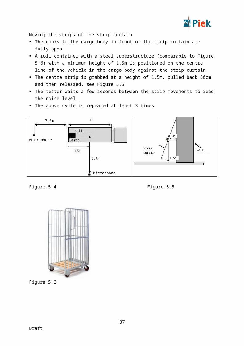
Moving the strips of the strip curtain The doors to the cargo body in front of the strip curtain are fully open A roll container with a steel superstructure (comparable to Figure 5.6) with a minimum height of
1.5m is positioned on the centre line of the vehicle in the cargo body against the strip curtain The centre strip is grabbed at a height of 1.5m, pulled back 50cm and then released, see Figure
5.5 The tester waits a few seconds between the strip movements to read the noise level The above cycle is repeated at least 3 times
Figure 5.4 Figure 5.5
Figure 5.6
26Draft
7.5m
Microphone 1
Microphone 2
7.5m
Roll container
Strip curtain
Roll containerStrip curtain
0.5m
1.5m

6. Methods of measurement for the tailboard and walls of commercial vehicles and lashing devices
This section deals with the methods of measurement regarding the use of the tailboard, fastening the load and moving transport equipment over the tailboard, floor and walls of the cargo body. All tests described in this section are conducted with an empty cargo body.
6.1 Measuring arrangement Two microphones are placed around the vehicle, with its engine switched off (see Figure 6.1): One at 7.5m from the rear, on the axis of the vehicle One at the side of the vehicle (tailboard operation side), 7.5m from the axis and at the halfway
point of the cargo body length (L/2)
The microphones are 1.2m above the paved surface If the drive system is located on the other side of the lorry than the controls, a measuring point is
selected on that side as well and a measurement taken
Figure 6.1 Microphone positions for measurements near the tailboard, cargo body and fasteners
6.2 Tailboard The tailboard is a platform at the rear of the lorry that can be raised. It is used to load and unload goods in roll containers or pallet trucks from the cargo body floor level to street level and vice versa. The tailboard is hydraulically driven. The hydraulic pump is electrically powered. This section describes the method of measurement for the power source of the tailboard and the roll-off stops.
6.2.1 Opening and closing The method of measurement for opening and closing the tailboard is as follows: The noise measurement is taken during a complete cycle of opening and closing the tailboard See Figure 6.1 for the measuring points. Microphone 2 is at the side of the tailboard drive system. The cycle is repeated and measured three times
27Draft
Microphone 1
7.5m
road axis
Microphone 2
Tailboard controls
7.5m

The noise measurement begins as soon as the tailboard (in the closed position) is activated, followed by the complete lowering cycle, including any folding out, until the tailboard touches the ground. The tailboard must lie on the ground so that a roll container can be rolled onto the tailboard. The folding-up cycle then follows until the tailboard is fully folded up. The measurement is stopped
The measurement result is the higher of the two energetic average values of the readings (minimum of 3 per measuring point) at both measuring points, rounded to a whole number in accordance with Section 3.3
6.2.2 Roll-off stop The roll-off stop is a small folding barrier built into the tailboard near the rear edge of the tailboard. In its raised position, this barrier prevents a roll container from rolling off the tailboard.
The method of measurement for the roll-off stop is as follows: The tailboard is in its lowest position See Figure 6.1 for the measuring points The roll-off stop is folded down and raised at least five times using one’s foot. A pause of several
seconds is added between folding down and raising. If there are several ways to lock the stop in place, all the methods must be tested
The measurement result is the higher of the two energetic average values of the readings (minimum of 5 times raising and pushing down) at both measuring points, rounded to the nearest whole number in accordance with Section 3.3
6.3 Rolling noise When rolling transportation equipment over a tailboard, through the cargo body or over a plate bridging a difference in height, both the transportation equipment and the plate or lift can create noise. This section describes a method of measurement for evaluating only the noise radiated by the plate or lift. To obtain a collision comparable with practical conditions, a modified ‘quiet’ roll container is used as shown in Figure 6.2. The modified roll container must be fitted with four hard (shore 100) standard plastic wheels (no rubber tyres) with a diameter of 100 mm. The roll container is loaded with a sandbag weighing 25 kg.
28Draft
Figure 6.2: Schematic representation of a ‘quiet’ roll container with hard standard plastic wheels (no rubber tyres) with a diameter of 100 mm and a 25 kg sandbag as load.

6.3.1 Rolling over the tailboard The method used to evaluate the noise produced in rolling over the tailboard is as follows: The tailboard is horizontal in its highest position, extending from the floor of the van or lorry The rolling speed must be approx. 3 kph See Figure 6.1 for the measuring points The ‘quiet’ roll container (see Figure 6.2) is rolled at least three times from left to right and back
(perpendicular to the driving direction) and at least three times from front to rear and back (in the driving direction) without rolling over the gap between the tailboard and the cargo body. (back and forth is 1 cycle). If the platform of the tailboard consists of several components, all the components must be measured.
The measurement result is the energetic average value of the readings (minimum of 6 per measuring point) at both measuring points, rounded to a whole number in accordance with Section 3.3
6.3.2 Rolling over the floor of the cargo body The method used to evaluate noise production while rolling over the floor of the cargo body of the commercial vehicle is as follows: The tailboard is horizontal in its highest position, extending from the floor of the van or lorry The rolling speed must be approx. 3 kph See Figure 6.1 for the measuring points The doors are open as wide as possible The ‘quiet’ roll container (see Figure 6.2) is rolled into the cargo body, starting at the entrance to
the cargo body, to the rear panel and back If the floor consists of several components, all the components must be measured There must be no collisions with the wall while rolling The measurement cycle is carried out and measured at least three times (back and forth is 1 cycle) The measurement result is the energetic average value of the readings (minimum of 3 per
measuring point) at both measuring points, rounded to a whole number in accordance with Section 3.3
6.3.3 Rolling over transitions (e.g. from tailboard to cargo body floor) The method used to evaluate the noise occurring while rolling over the gap between the tailboard and the cargo body floor is as follows: The ‘quiet’ roll container (see Figure 6.2) is rolled onto and off the tailboard from the cargo body,
in the driving direction of the vehicle. The rolling speed must be approx. 3 kph See Figure 6.1 for the measuring points The measurement cycle is carried out and measured at least three times (back and forth is 1 cycle) The measurement result is the energetic average value of the readings (minimum of 3 per
measuring point) at both measuring points, rounded to a whole number in accordance with Section 3.3
6.4 Noise of collision with walls of the cargo body6.4.1 Wall
29Draft

The noise radiated by the wall of the cargo body as a result of colliding roll containers, for example, is evaluated as follows: The collision is simulated using a ball on a cord, which is released at a distance from the side wall
and then collides with the wall (see Figure 6.3). By using a ball (that radiates little noise) instead of a roll container, for example, only the noise radiated from the wall is measured, in analogy with the rolling noise measurement (see Section 6.4). In principle, measurements are taken on one side of the vehicle only
A steel ball weighing 1 kg hangs on a cord. The distance from the centre of the ball to the fastening point (directly above the collision point) of the cord is 1m. The ball is released at a distance of 10cm from the wall (see Figure 6.3). The ball is caught after the collision. The noise level is read
If there are wheel housings in the cargo body, a single collision point on the vertical wall of the wheel housing is chosen. The fastening point of the cord is kept directly above the collision point on the wheel housing. The collision is equivalent to the collision with the wall
The collision points are 15cm above the floor and at a distance of 1/4L, 1/2L and 3/4L from the rear opening of the cargo body
If any parts protrude in relation to the collision points located 15cm above the floor, these must also be measured. Only the highest point of these protruding parts should be measured
See Figure 6.4 for the measuring points.
A pause of a few seconds is added between the collisions to read the noise level.
6.4.2 Front end A steel ball weighing 1 kg hangs on a cord. The distance from the centre of the ball to the
fastening point (directly above the collision point) of the cord is 1m. The ball is released at a distance of 10cm from the front end (see Figure 6.3). The ball is caught after the collision. The noise level is read
The collision points are 15cm above the floor and at a distance of 1/3L from the side walls of the cargo body
If any parts protrude in relation to the collision points located 15cm above the floor, these must also be measured. Only the highest point should be measured
See Figure 6.5 for the measuring points.
A pause of a few seconds is added between the collisions to read the noise level.
30Draft

Figure 6.5
31Draft
ball
floor
wall
0.15m0.1m
7.5m
7.5m7.5m
microphone
microphone
Microphone 2
7.5m
7.5m
Figure 6.3
Figure 6.4

The measurement is performed at least three times per point.
The measurement result is determined as follows: the energetic average of 3 readings is calculated for each measuring point and collision point. The measurement result is the highest of the 6 energetic average values of the readings, rounded to a whole number in accordance with Section 3.3
6.5 Load fastening system Straps and clamping blocks are used to secure the load in the cargo body. Setting and releasing the load fasteners creates noise in the fastener itself and the wall, floor or ceiling of the cargo body. The following methods are intended to determine the noise resulting from securing, strapping down and collisions.
6.5.1 Straps The method of measurement is as follows: Attach the hooks of the straps to both fastening rails of the cargo body. Pull the strap tight. It is then released again This cycle is carried out at least 3 times for each point (3 times in the front, 3 in the middle and 3
in the back) See Figure 6.1 for the measuring points The measurement result is determined as follows: the energetic average of 3 readings is
calculated for each measuring point and fastening point. The measurement result is the highest of the 6 energetic average values of the readings at both measuring points, rounded to a whole number in accordance with Section 3.3
6.5.2 Clamping blocks The method of measurement is as follows: Place the clamping block in both fastening rails in the cargo body Click the clamping block into place. It is then released again This cycle is carried out at least 3 times for each point (3 times in the front, 3 in the middle and 3
in the back) See Figure 6.1 for the measuring points The measurement result is determined as follows: the energetic average of 3 readings is
calculated for each measuring point and fastening point. The measurement result is the highest of the 6 energetic average values of the readings at both measuring points, rounded to a whole number in accordance with Section 3.3
32Draft

7. Method of measurement for shopping trolleys and pallet trucks
7.1 Rolling noise In order to evaluate the noise of shopping trolleys, manually and electrically operated pallet trucks while rolling, a smooth surface is used with standardised irregularities applied to it. The surface itself must not radiate noise.
The irregularities consist of steel strips, preferably glued to the surface, in accordance with Figure 7.1. A different attachment method may be used, possibly combined with glue. The transport equipment is measured unloaded.
Measuring course The measuring course for these three types of transport equipment is as follows (see Figure 7.1): The surface must consist of smooth asphalt or concrete The irregularities consist of four rectangular metal strips 30mm wide and 5mm high, as indicated
in Figure 7.1 The strips are at least 1.5 times the width of the transport equipment in length The strips are preferably glued or attached over the entire length of the surface The four strips are applied to the measuring course in parallel at a distance of 2m from each other The test course is at least 1.5 times as wide as the transport equipment being evaluated The length of the measuring course is 12m
Figure 7.1: Situation for measuring the rolling noise of roll containers, pallet trucks and shopping trolleys.
Measurement procedureThe measurement procedure is as follows: The transport equipment is rolled over the course at a walking speed of approximately 3 kph The rolling direction is perpendicular to the irregularities, in both directions All wheels must pass over the irregularities The transport equipment is unloaded When measuring the pallet truck, the fork is in its lowest position The measuring course is covered at least 3 times
33Draft
Microphone
7.5m
As measuring course
StripsTransport device

See Figure 7.1 for the measuring point The measurement result is the energetic average value of the readings (minimum of 3) at the
measuring point, rounded to a whole number in accordance with Section 3.3
7.2 Lowering and raising electrically and manually operated pallet trucksThe method of measurement applied to lowering and raising electrically and manually operated pallet trucks is the one used for evaluating the lowering and raising of a forklift truck. See Section 9.2 for this.
34Draft

8. Method of measurement for roll containers, rollies and dollies The roll container is a transporter for a large range of products. The roll container has a folding base and sides that can be hinged, so that the empty roll containers can be nested together for moving. The rolly (half Europallet) and the dolly (quarter Europallet) are wheeled pallets for transporting crates and boxes, and are used, among other things, for direct positioning. The empty rollies and dollies are stacked for moving around.
8.1 Rolling noise 8.1.1 Loaded The method of measurement for rolling noise is identical to that used for shopping trolleys and pallet trucks described in Section 7.1, with the difference that the strips are 3mm high. The roll container and the rolly are loaded with a weight of 100kg; the dolly is loaded with a weight of 50kg. If several loading shelves can be placed in a roll container, rolly or dolly, the test must be performed without additional loading shelves and with 75% of the maximum number of loading shelves (number must be rounded up). When using several loading shelves, the load must be evenly distributed with a minimum of 10kg.
8.1.2 Rolling nested roll containers The method of measurement involves rolling three nested roll containers in accordance with the method of measurement described in Section 8.1.1, but unloaded.
8.1.3 Rolling empty roll containers that cannot be nested The method of measurement for rolling noise is identical to that used for shopping trolleys and pallet trucks described in Section 7.1, with the difference that the strips are 3mm high. If several loading shelves can be placed in a roll container, the test must be performed without additional loading shelves and with 75% of the maximum number of loading shelves (number must be rounded up).
8.1.4 Rolling stacked rollies and dollies The rollies and dollies are rolled along the measuring course in accordance with the method of measurement described in Section 8.1.1, with 5 stacked but unloaded rollies or dollies.
8.2 Colliding/nesting roll containers For the collision noise, the method of measurement involves nesting the roll containers. One roll container is rolled into two already nested roll containers, as is customary with nesting.
Nest test
35Draft
Approx. 3 kph2 nested roller containers
braking chock

Figure 8.1: Test. Figure 8.1 shows the measuring arrangement. The floor surface should consist of smooth asphalt or concrete. The two nested roll containers should be stopped by a braking chock or a similar obstacle.
Measurement procedure The measurement procedure is as follows: Roll container 1 is pushed against the nested roll containers 2 and 3, at a speed of approximately
3 kph, as is customary with nesting The transport equipment is unloaded and of the same type The microphone is at 7.5m from the collision point on a line perpendicular to the rolling direction The test is repeated at least three times The measurement result is the energetic average value of the readings (minimum of 3) at the
measuring point, rounded to a whole number in accordance with Section 3.3
8.3 Placing and removing additional loading shelves No additional loading shelves are present in a roll container During the measurement, an additional loading shelf is placed; after placing it, the tester waits for
a few seconds, after which the additional loading shelf is removed The cycle is repeated at least 3 times The microphone is at 7.5m from the centre point of the roll container The measurement result is the energetic average value of the readings (minimum of 3) at the
measuring point, rounded to a whole number in accordance with Section 3.3
8.4 Stacking rollies and dollies The empty rollies and dollies are stacked for moving around.
Measurement procedure The measurement procedure is as follows: The transport equipment is unloaded and of the same type The microphone is placed at 7.5m from the stacking point An empty rolly or dolly is lifted up and placed on a stationary rolly or dolly from standing height,
while measuring the noise level. The next rolly or dolly is then lifted up and placed on the two stacked rollies or dollies from standing height and the noise level is measured. Finally, one more rolly or dolly is placed on the stacked rollies or dollies and the noise level is measured
The measurement result is the energetic average value of the 3 measurements, rounded to a whole number in accordance with Section 3.3
36Draft
9. Method of measurement for forklift trucks and mobile forklift trucks A mobile forklift truck differs from other forklift trucks in that it is connected to the rear of the lorry during transport. There are versions for which the operating personnel are not seated on the forklift but walk behind it. There are no functional differences. Like a forklift truck, a mobile forklift truck has its own drive system. Forklift trucks and mobile forklift trucks are evaluated in the same manner in terms of noise production during driving and lifting. Because of peak noise, collisions are important when driving over irregularities. A driving test is therefore proposed in which forklifts are driven over several standardised irregularities, see Figure 7.1. For a mobile forklift truck, the (collision) noise that occurs when connecting it to the lorry is also measured.
9.1 Driving The requirements for the measuring course and the forklift to be measured are: See Figure 7.1 for the layout of the measuring course At least another 10m of smooth surface must be available before and after the measuring course
with irregularities The forklift is unloaded The forks are in their lowest position, so that the scoops of the pallet truck do not touch the strips The forklift is tested in its standard version as described by the manufacturer The engine and hydraulic system (see 8.2) of the forklift truck must be within the limits of the
operating temperature indicated by the manufacturer
Measurement procedure The measurement procedure is as follows: The forklift truck is driven over the measuring course at a constant speed of 13 ± 2 kph or, if this is
not possible, the maximum speed indicated by the supplier For a forklift truck with a manual gearbox, the highest gear is selected For mobile forklift trucks that are operated while walking, the driving speed is approx. 3 kph Each side of the forklift truck (left and right) is measured at least 3 times The measurement result is the energetic average value of the readings (minimum of 6) at both
measuring points, rounded to a whole number in accordance with Section 3.3
9.2 Evaluation of lifting Measurements are taken at 4 measuring points (front, side (2), rear) around the stationary forklift. The evaluation distance of 7.5m to the microphone is from the vertical projection of the geometric centre of the forklift to the reflecting surface.
The following measurement procedure for evaluating the lifting noise must be completed: The forklift lifts a load equal to 70% of the actual capacity (permitted by the manufacturer) from
minimum to maximum height at maximum acceleration Each side of the forklift truck is measured at least 2 times The measurement result is the energetic average value of the readings (minimum of 8) at the
measuring points, rounded to a whole number in accordance with Section 3.3
37Draft

9.3 Evaluation of connecting mobile forklift truck This test uses an unloaded lorry. The doors and panels of the vehicle are closed. Measurements are taken in two directions (see Figure 9.1).
Figure 9.1: Test for mobile forklift truck
The following measurement procedure must be completed to evaluate the noise when connecting and disconnecting the mobile forklift truck: The lorry is placed in the measuring position and its engine is switched off The measurement begins before the engine of the mobile forklift truck is started, on the lorry The mobile forklift truck is unloaded and placed on the ground, after which it is reversed until the
forklift is clear of the lorry The mobile forklift truck is then driven back into the lorry clamp The truck is put in the transport position and locked The engine is switched off and the measurement stops Measurements are taken at least three times. The measurement result is the energetic average
value of the readings (minimum of 6) at both measuring points, rounded to a whole number in accordance with Section 3.3
38Draft
Microphone 1
7.5m
road axis
Microphone 2
7.5m
Connected mobile forklift truck

10. Method of measurement for transport refrigeration Refrigeration is used to keep perishable goods at the correct temperature during transport [6]. The following systems are distinguished:
10.1 Types of transport refrigeration10.1.1 Refrigeration system with integrated combustion engine A refrigeration system with a compressor, one or more evaporators, a control valve, a condenser and an integrated combustion engine that provides the power. The unit, possibly excluding the evaporator(s), is placed in an enclosure that is attached against the front end of the cargo body or underneath the floor. An electric motor may also be present within the enclosure to power the compressor when the lorry’s engine is switched off. The electric motor is then connected to the public mains.
10.1.2 Refrigeration system without separate combustion engineA refrigeration system with a compressor, one or more evaporators (possibly in the cargo body), a control valve, a condenser. The unit is powered by the lorry's engine or by a separate diesel engine mounted underneath the loading body, or the unit is connected directly to the vehicle's battery. The following are distinguished:10.1.2.1 Electrical systems in which a generator is powered directly or indirectly by the lorry's engine.
For a direct drive system, the generator is powered by the lorry's engine without any other components. One example of an indirect drive system is having a hydraulic transmission mounted between the lorry's engine and the generator.
10.1.2.2 Systems in which the mechanical compressor of the refrigeration unit is powered directly by the lorry's engine.
10.1.2.3 Electrical systems stated under 10.1.2.1 with additional support by a (quickly exchangeable) powerpack ((diesel) generator set). The latter consists of a (diesel) engine with a generator that can power the refrigeration system when the lorry's engine is switched off.
10.1.2.4 Systems in which the original integrated diesel engine has been removed and mounted in a separate diesel engine enclosure underneath the cargo body.
10.1.2.5 Systems in which the unit is connected directly to the vehicle's battery.
10.1.3 Refrigeration system based on an “open” gas systemA cooling system with a control valve in which gas (e.g. nitrogen or carbon dioxide) evaporates directly in the cargo body or indirectly in one or more evaporators.
10.1.4 Refrigeration system with eutectic mass In this system, a eutectic mass is installed in the body instead of the evaporator. The eutectic refrigerant is usually frozen when the vehicle is stationary (at night). The cooling occurs because the cooled air is heavier and floats down in the cargo body. It is also possible to use a fan in the cargo body to lead air along the eutectic mass and cool it. This system is expected to be sufficiently quiet in terms of the peak noise issue and will not be discussed any further.
If the vehicle is equipped with a PEAK mode switch, the tests can also be performed with PEAK mode activated. PEAK mode must be driver-independent. The driver must not be able to influence PEAK mode either, see also 10.4.
39Draft

10.2 Measuring arrangementsThe lorry with transport refrigeration is placed in the middle of the measuring surface.
10.2.1 Measuring points for refrigeration unit at front endIf the refrigeration unit is mounted to the front end of the vehicle, measurements are taken in 2 directions (angular width is 90o) at the front of the transport refrigeration unit in the horizontal plane at a height of 3m and at 1 measuring point above the transport refrigeration unit (see Figure 10.1). The distance from the 2 measuring points in the horizontal plane to the geometric centre of the refrigeration unit is 7.5m. By way of exception, measurements may be taken at a distance of 2m above the refrigeration unit instead of 7.5m, converting the level to 7.5m as follows: Lp, 7.5m calculated = Lp, 2m measured -11 dB(A), to a noise level at a distance of 7.5m. If measurements can be taken at 7.5m above the vehicle, this will be preferable.
Figure 10.1 Measuring points around the transport refrigeration unit mounted to the front end
10.2.2 Measuring points for refrigeration unit underneath cargo bodyIf the refrigeration unit is not mounted to the front end, but underneath the cargo body, the measuring points indicated in Figure 10.2 will be used rather than the measuring points indicated in Figure 10.1.
Figure 10.2 Measuring points if the refrigeration unit is mounted underneath the vehicle.
40Draft
7.5m
7.5 m, in exceptional cases 2 m
7.5m
Measuring points for refrigeration unit underneath the vehicle
1.2m

10.2.3 Additional measuring point for unit powered by lorry's engineIf the lorry's engine is used to power the refrigeration unit, a measuring point at a distance of 7.5m from the front of the engine compartment and at a height of 1.2m will be chosen in addition to the measuring points stated in Figure 10.1 or 10.2, see Figure 10.3. The entire installation must be operational during the measurements.
Figure 10.3: Additional measuring point for unit powered by lorry's engine
10.2.4 Additional measuring points for drive system underneath cargo bodyIf the drive system for the refrigeration unit is mounted underneath the vehicle (10.3.4 and 10.3.5), measuring points will be selected at 7.5m from the sides of the vehicle, positioned parallel to the centre of the drive unit (e.g. diesel engine, compressor, hydraulic motor, etc.) at a height of 1.2m in accordance with Figure 10.4, in addition to the measuring points indicated in Figure 10.1 or 10.2. The entire installation must be operational during the measurements.
Figure 10.4 Additional measuring points for drive system underneath cargo body.
41Draft
7.5m
Additional measuring point for unit powered by lorry's engine
1.2m
7.5m
Additional measuring points for drive system underneath vehicle
1.2m

10.3 Measurement proceduresThere are different measurement procedures for the refrigeration systems described in 10.1. These measurement procedures are described in 10.3.
It may be possible to drive a refrigeration system in various ways, for example, using an integrated combustion engine and through a power connection with the public mains. If a refrigeration system can be driven in various ways, all the possible methods must be tested.
Only a full system can be evaluated; individual parts such as a (quickly exchangeable) powerpack cannot be evaluated separately.
42Draft

10.3.1 Evaluation of refrigeration system with integrated combustion engine (see 10.1.1 Refrigeration system with integrated combustion engine)The following measurement procedure must be completed: Position lorry in measuring location, switch off engine. To guarantee that the refrigeration system to be measured operates under full load, the noise
measurement will have to be taken at a cargo body temperature of between +15°C and +5°C, with the ‘set’ temperature at -/- 20°C. If the refrigeration system cannot be set to a ‘set’ temperature of -/- 20°C, the refrigeration system must be set to the lowest possible ‘set’ temperature
Start the diesel engine of the refrigeration unit, turn the refrigeration unit on and set it to the‘diesel-high’ operating condition or to PEAK mode (unit settings in accordance with the manufacturer's instructions)
Main evaporator/evaporator with greatest capacity is operational Read the maximum noise levels every 10 seconds for about 30 seconds (at least 3 readings) The measurement result is the highest value read from the measuring points and any value
corrected to a distance of 7.5m, rounded to a whole number in accordance with Section 3.3
For the ‘diesel-low’ operating condition, the noise level is lower than for the ‘diesel-high’ operating condition. As the diesel engine runs at reduced RPM in the ‘low’ setting, this situation will therefore not be evaluated.
If the compressor can be powered by an additional electric motor (connection to the public mains), the refrigeration system will also be measured in accordance with 10.3.6.
10.3.2 Evaluation of refrigeration system without separate combustion engine (see 10.1.2.1 Refrigeration system without separate combustion engine)The following measurement procedure must be completed: Position lorry in measuring location, leave lorry engine running. To guarantee that the refrigeration system to be measured operates under full load, the noise
measurement will have to be taken at a cargo body temperature of between +15°C and +5°C, with the ‘set’ temperature at -/- 20°C. If the refrigeration system cannot be set to a ‘set’ temperature of -/- 20°C, the refrigeration system must be set to the lowest possible ‘set’ temperature.
Turn on refrigeration unit and set it to the ‘fast’ or ’high’ operating condition or to PEAK mode (unit settings in accordance with the manufacturer's instructions).
Main evaporator/evaporator with greatest capacity is operational. Read the maximum noise levels every 10 seconds for about 30 seconds (at least 3 readings). The measurement result is the highest value read from the measuring points and any value
corrected to a distance of 7.5m, rounded to a whole number in accordance with Section 3.3.
At the current state of the art, the noise level of the lorry engine will be higher than the noise level produced by the refrigeration system when performing the above measurement procedure. Until vehicles are introduced that can be used to perform the above test, the refrigeration unit may be measured using a connection to the public mains in accordance with measurement procedure 10.3.6.
If the system has an “overnight cooling system” using a power connection and an electric drive system, this system must also be tested as stated under 10.3.6.
43Draft

10.3.3 Evaluation of refrigeration system without separate combustion engine (see 10.1.2.2 Refrigeration system without separate combustion engine, with a compressor directly connected to the lorry's engine)The following measurement procedure must be completed: Position lorry in measuring location, leave lorry engine running and bring it to its operating
temperature. To guarantee that the refrigeration system to be measured operates under full load, the noise
measurement will have to be taken at a cargo body temperature of between +15°C and +5°C, with the ‘set’ temperature at -/- 20°C. If the refrigeration system cannot be set to a ‘set’ temperature of -/- 20°C, the refrigeration system must be set to the lowest possible ‘set’ temperature.
Turn on refrigeration unit and set it to the ‘fast’ or ’high’ operating condition or to PEAK mode (unit settings in accordance with the manufacturer's instructions).
Main evaporator/evaporator with greatest capacity is operational. Read the maximum noise levels every 10 seconds for about 30 seconds (at least 3 readings). The measurement result is the highest value read from the measuring points and any value
corrected to a distance of 7.5m, rounded to a whole number in accordance with Section 3.3.
At the current state of the art, the noise level of the lorry engine will be higher than the noise level produced by the refrigeration system when performing the above measurement procedure. Until vehicles are introduced that can be used to perform the above test, the refrigeration unit may be measured using a connection to the public mains in accordance with the measurement procedure below. If the system has an “overnight cooling system” using a power connection and an electric drive system, this system must also be tested as stated under 10.3.6
10.3.4 Evaluation of refrigeration system without separate combustion engine (see 10.1.2.3 Refrigeration system without separate combustion engine, with additional support by a (quickly exchangeable) powerpack)
The following measurement procedure must be completed if the system can operate without a functioning powerpack ((diesel) generator set): Position lorry in measuring location, switch off engine. Electrically connect refrigeration system to the public mains. To guarantee that the refrigeration system to be measured operates under full load, the noise
measurement will have to be taken at a cargo body temperature of between +15°C and +5°C, with the ‘set’ temperature at -/- 20°C. If the refrigeration system cannot be set to a ‘set’ temperature of -/- 20°C, the refrigeration system must be set to the lowest possible ‘set’ temperature.
Turn on refrigeration unit and set it to the ‘fast’ or ’high’ operating condition or to PEAK mode (unit settings in accordance with the manufacturer's instructions).
Main evaporator/evaporator with greatest capacity is operational. Read the maximum noise levels every 10 seconds for about 30 seconds (at least 3 readings). The measurement result is the highest value read from the measuring points and any value
corrected to a distance of 7.5m, rounded to a whole number in accordance with Section 3.3.
The following measurement procedure must also be followed if the system has a functioning powerpack ((diesel) generator set):
Position lorry in measuring location, switch off engine.
44Draft

Start powerpack and set it to the ‘fast’ or ’high’ operating condition (unit settings in accordance with the manufacturer's instructions). Run the engine until it reaches its operating temperature.
To guarantee that the refrigeration system to be measured operates under full load, the noise measurement will have to be taken at a cargo body temperature of between +15°C and +5°C, with the ‘set’ temperature at -/- 20°C. If the refrigeration system cannot be set to a ‘set’ temperature of -/- 20°C, the refrigeration system must be set to the lowest possible ‘set’ temperature.
Turn on refrigeration unit and set it to the ‘fast’ or ’high’ operating condition or to PEAK mode (unit settings in accordance with the manufacturer's instructions).
Main evaporator/evaporator with greatest capacity is operational. Read the maximum noise levels every 10 seconds for about 30 seconds (at least 3 readings). The measurement result is the highest value read from the measuring points and any value
corrected to a distance of 7.5m, rounded to a whole number in accordance with Section 3.3.
For the ‘slow’ or ‘low’ operating condition, the noise level is lower than for the ‘diesel-high’ operating condition. As the diesel engine runs at reduced RPM in the ‘low’ setting, this situation will therefore not be evaluated.
10.3.5 Evaluation of refrigeration system with external combustion engine (see 10.1.2.4 Systems with the original integrated diesel engine installed externally) The following measurement procedure must be completed: Position lorry in measuring location, switch off lorry engine Start diesel engine of refrigeration unit and leave it running until it reaches its operating
temperature. Turn on refrigeration unit and set it to the ‘fast’ or ’high’ operating condition or to PEAK mode (unit settings in accordance with the manufacturer's instructions).
To guarantee that the refrigeration system to be measured operates under full load, the noise measurement will have to be taken at a cargo body temperature of between +15°C and +5°C, with the ‘set’ temperature at -/- 20°C. If the refrigeration system cannot be set to a ‘set’ temperature of -/- 20°C, the refrigeration system must be set to the lowest possible ‘set’ temperature.
Main evaporator/evaporator with greatest capacity is operational. Read the maximum noise levels every 10 seconds for about 30 seconds
(at least 3 readings). Read the maximum noise levels per measuring point during the entire cycle.
The measurement result is the highest value of the measuring points and any value corrected to a distance of 7.5m, rounded to a whole number in accordance with Section 3.3.
If the compressor can be powered by an additional electric motor (connection to the public mains), the refrigeration system will also be measured in accordance with 10.3.6.
10.3.6 Evaluation of electrically powered refrigeration system with a connection to the public mains and refrigeration system based on an “open” gas system with a connection to the public mains
The following measurement procedure must be completed: Position lorry in measuring location, switch off lorry engine or other combustion engine. Electrically connect refrigeration system to the public mains. To guarantee that the refrigeration system to be certified operates under full load, the noise
45Draft

measurement will have to be taken at a cargo body temperature of between +15°C and +5°C, with the ‘set’ temperature at -/- 20°C. If the refrigeration system cannot be set to a ‘set’ temperature of -/- 20°C, the refrigeration system must be set to the lowest possible ‘set’ temperature.
Turn on refrigeration unit and set it to the ‘fast’ or ’high’ operating condition or to PEAK mode (unit settings in accordance with the manufacturer's instructions).
Main evaporator/evaporator with greatest capacity is operational. Read the maximum noise levels every 10 seconds for about 30 seconds (at least 3 readings). The measurement result is the highest value read from the measuring points and any value
corrected to a distance of 7.5m, rounded to a whole number in accordance with Section 3.3.
10.3.7 Evaluation of electrically powered refrigeration system with a connection to the vehicle's battery and refrigeration system based on an “open” gas system with a connection to the vehicle's batteryThe following measurement procedure must be completed: Position lorry in measuring location, switch off engine. To guarantee that the refrigeration system to be measured operates under full load, the noise
measurement will have to be taken at a cargo body temperature of between +15°C and +5°C, with the ‘set’ temperature at -/- 20°C. If the refrigeration system cannot be set to a ‘set’ temperature of -/- 20°C, the refrigeration system must be set to the lowest possible ‘set’ temperature
Turn on refrigeration system and set it to the ‘fast’ or ’high’ operating condition or to PEAK mode (unit settings in accordance with the manufacturer's instructions)
Main evaporator/evaporator with greatest capacity is operational Read the maximum noise levels every 10 seconds for about 30 seconds (at least 3 readings) The measurement result is the highest value read from the measuring points and any value
corrected to a distance of 7.5m, rounded to a whole number in accordance with Section 3.3
If the compressor can be powered by an additional electric motor (connection to the public mains), the refrigeration system will also be measured in accordance with 10.3.6.
10.4 Refrigeration system with PEAK modeFor a refrigeration unit that is fitted with a driver-independent PEAK mode control system, it must be demonstrated that PEAK mode functions in addition to the above methods of measurement. PEAK mode must ensure that the refrigeration unit meets the legal noise requirements within a distance of 300 metres from the loading/unloading location.
There are several types of driver-independent PEAK modes. The basic principle of a PEAK mode is that it is driver-independent and that, outside of the PEAK-specified time frames and outside of the so-called PEAK locations, the machine can be set to maximum power with technical tools. In other words, PEAK mode is the normal operating setting of the machine. In case of a defect in the technical tool or other faults relating to the functioning of PEAK mode, the machine must operate in PEAK mode. The functioning of PEAK mode must be guaranteed. The functioning of PEAK mode must also be demonstrated and described in the report.
46Draft

11. ReportingThe report must state all relevant matters that are required for the certification of a product. Details that must always be included in the measurement report are:
Product details in accordance with the form below:* Vehicle doors, hatches, hinged and roller doorsDescription of vehicle doors, hatches, hinged and roller doors:
ManufacturerMakeTypeHingeMakeTypeNumberPicture Place picture hereLocking systemMakeTypeNumberPicture Place picture hereDoor gripMakeTypeNumberPicture Place picture hereDoor catchMakeTypeNumberPicture Place picture hereRubberMakeTypeNumberPicture Place picture hereOtherPart nameMakeTypeNumberPicture Place picture herePeak-specific modificationPart nameMakeTypeNumberPicture Place picture here
47Draft

* Air curtainDescription of air curtain:
ManufacturerMakeTypeFanMakeTypeNumberRPMPicture Place picture hereEnclosureMaterialMaterial thicknessPictureInsulation materialInsulation materialInsulation material thicknessPicture Place picture hereOtherPart nameMakeTypeNumberPicture Place picture herePeak-specific modificationPart nameMakeTypeNumberPicture Place picture here
* Roller doorDescription of roller door:
ManufacturerMakeTypeWheelsMakeTypeNumberPicture Place picture hereWheel bearingMakeType
48Draft

NumberPicture Place picture hereLocking systemMakeTypeNumberPicture Place picture hereRubberMakeTypeNumberPicture Place picture hereStopTypeMaterialPicture Place picture hereIf electricElectric motorMakeTypeRPMPicture Place picture hereIf pneumaticCylinderMakeTypePicture Place picture hereOpening speedOtherPart nameMakeTypeNumberPicture Place picture herePeak-specific modificationPart nameMakeTypeNumberPicture Place picture here
* Sliding panelDescription of sliding panel:
ManufacturerMakeTypeWheels
49Draft

MakeTypeNumberPicture Place picture hereWheel bearingMakeTypeNumberPicture Place picture hereLocking systemMakeTypeNumberPicture Place picture hereStopTypeMaterialPicture Place picture hereOtherPart nameMakeTypeNumberPicture Place picture herePeak-specific modificationPart nameMakeTypeNumberPicture Place picture here
* Sliding partitionDescription of sliding partition
ManufacturerMakeTypeWheelsMakeTypeNumberPicture Place picture hereWheel bearingMakeTypeNumberPicture Place picture hereLocking system
50Draft

MakeTypeNumberPicture Place picture hereLocking systemMakeTypeNumberPicture Place picture hereRubberMakeTypePicture Place picture hereStopTypeMaterialPicture Place picture hereOtherPart nameMakeTypeNumberPicture Place picture herePeak-specific modificationPart nameMakeTypeNumberPicture Place picture here
* StepsDescription of steps
ManufacturerMakeTypeMaterialTypeThicknessPicture Place picture hereRubberMakeTypePicture Place picture hereStopTypeMaterialPicture Place picture hereOther
51Draft

Part nameMakeTypeNumberPicture Place picture herePeak-specific modificationPart nameMakeTypeNumberPicture Place picture here
* Strip curtainDescription of curtain
ManufacturerMakeTypeWheelsMakeTypeNumberPicture Place picture hereWheel bearingMakeTypeNumberPicture Place picture hereStopTypeMaterialPicture Place picture hereStripsNumberMaterialThicknessPicture Place picture hereOtherPart nameMakeTypeNumberPicture Place picture herePeak-specific modificationPart nameMakeTypeNumber
52Draft

Picture Place picture here
* TailboardDescription of tailboard
ManufacturerMakeTypeVersion rear-closing tailboard / slides underneath vehicle / internal vertical
tailboardEngineMakeTypeRPMPicture Place picture herePumpMakeTypeRPMPicture Place picture hereRoll-off stop typeRoll-off stop modificationsPicture Place picture hereRollersMakeTypeNumberPicture Place picture hereRubber possibly present on rear frameMakeTypeThicknessNumberPicture Place picture hereRubber possibly present at bottom of cargo bodyMakeTypeThicknessNumberPicture Place picture herePlatformMaterialCoating materialCoating thickness
53Draft

Picture Place picture hereOtherPart nameMakeTypeNumberPicture Place picture herePeak-specific modificationPart nameMakeTypeNumberPicture Place picture here
* FloorDescription of floor:
ManufacturerMakeTypeFloorMakeTypeStructureThicknessPicture Place picture hereIf coating presentMakeTypeThicknessPicture Place picture hereAnti-skidPicture Place picture hereOtherPart nameMakeTypeNumberPicture Place picture herePeak-specific modificationPart nameMakeTypeNumberPicture Place picture here
54Draft

* WallDescription of wall:
ManufacturerMakeTypeWallMakeTypeMaterialStructureThicknessPicture Place picture hereIf impact plate presentMakeTypeDimensionsPicture Place picture hereOtherPart nameMakeTypeNumberPicture Place picture herePeak-specific modificationPart nameMakeTypeNumberPicture Place picture here
* Load fastening systemDescription of load fastening system
Locking systemManufacturerMakeTypeLocking system typeMaterialPicture Place picture hereRailManufacturerMakeTypeMaterial
55Draft

Picture Place picture hereOtherPart nameMakeTypeNumberPicture Place picture herePeak-specific modificationPart nameMakeTypeNumberPicture Place picture here
Refrigeration unitDescription of refrigeration unit:
ManufacturerMakeModelTypeWhere applicable: Variation on standard type:PEAK mode: Operating methodDrive system type: Powered by vehicle engine / Powered by separate diesel engine
Electrically powered / Diesel-electrically poweredNitrogen unit / Carbon dioxide unit
Diesel engineMakeTypeRPMPictureCompressorMakeTypeRPMPicture Place picture hereGenerator frequency (where applicable)RPM of condenser fan(s)OtherPart nameMakeTypeNumber
56Draft

Picture Place picture hereNoise insulation method:Enclosure materialMaterial thicknessPictureWhere applicable for separate drive systemEnclosure materialMaterial thicknessPictureInsulationInsulation materialInsulation material thicknessInsulation material typePicture Place picture hereDamping fitted inside enclosure
yes/no
Where applicable: water- or air-cooled generatorExhaust damperMakeTypeDimensions of exhaust damperLocation of exhaust damperRelease location of exhaust gasesPicture Place picture hereOtherPart namePart nameMakeTypeNumberPicture Place picture herePeak-specific modificationPart nameMakeTypeNumberPicture Place picture here
57Draft

* Drive noiseDescription of vehicle0. General0.1. Make (trade name of manufacturer): 0.2. Means of identification of type, if marked on the vehicle:1
0.2.1. Location of that marking: 0.3. Category of vehicle:2 0.4. Company name and address of manufacturer: 0.5. Name and address of the manufacturer's representative (if any): 0.6. Name(s) and address(es) of assembly plant(s): 0.7 Building series (model year):
1. General construction characteristics of the vehicle1.1. Photographs and/or drawings of a representative vehicle: 1.2. Number of axles and wheels:3
1.2.1. Powered axles (number, position, interconnection): 1.3. Position and arrangement of the engine:
2. Masses and dimensions 4 (in kg and mm) (Refer to drawing where applicable): 2.1. Range of vehicle dimensions (overall): 2.1.1. For chassis without bodywork: 2.1.1.1. Length: 2.1.1.2. Width: 2.1.2. For chassis with bodywork 2.1.2.1. Length: 2.1.2.2. Width: 2.13. Wheelbase:
2.2. Mass in running order5
(a) Minimum and maximum for each variant: (b) Mass of each version (a matrix shall be provided): 2.3. Technically permissible maximum laden mass stated by the manufacturer:6, 7
3. Power plant8
3.1. Manufacturer of the engine: 3.1.1. Manufacturer's engine code (as marked on the engine, or other means of identification):
3.2. Internal combustion engine3.2.1. Specific engine information3.2.1.1. Working principle: positive ignition/compression ignition, cycle fourstroke/two stroke/rotary9
3.2.1.2. Number and arrangement of cylinders:3.2.1.2.1. Firing order: 3.2.1.3. Engine capacity:10 …. cm3
58Draft

3.2.1.4. Rated maximum net power: ……. kW at …….. min–1 (manufacturer's declaredvalue)
3.2.2. Fuel feed3.2.2.1. By fuel injection (compression ignition only): yes/no93.2.2.1.1. Working principle: Direct injection/pre-chamber/swirl chamber93.2.2.1.2. Governor3.2.2.1.2.1. Type: 3.2.2.1.2.2. Speed at which Cut-off starts under load: …. min–13.2.2.2. By fuel injection (positive ignition only): yes/no93.2.2.2.1. Working principle: Intake manifold (single-/multi-point2)/directinjection/other (specify)
3.2.3. Intake system3.2.3.1. Air filter, drawings, or3.2.3.1.1. Make(s): 3.2.3.1.2. Type(s): 3.2.3.2. Intake silencer, drawings,3.2.3.2.1. Make(s): 3.2.3.2.2. Type(s):
3.2.4. Exhaust system3.2.4.1. Description and/or drawing of the exhaust system: 3.2.4.2. Exhaust silencer(s): Type, marking of exhaust silencer(s): Where relevant for exterior noise, reducing measures in the engine compartment and on the engine: 3.2.4.3. Location of the exhaust outlet: 3.2.4.4. Exhaust silencer containing fibrous materials: 3.2.5. Catalytic convertor: yes/no93.2.5.1. Number of catalytic convertors and elements (provide the information below for each separate unit):
3.3. Electric motor3.3.1. Type (winding, excitation):3.3.1.1. Maximum hourly output: ….….….….….…. kW3.3.1.2. Operating voltage: ….….….….…. V
3.4. Engine or motor combination: 3.4.1. Hybrid electric vehicle: yes/no9
3.4.2. Category of hybrid electric vehicle: off-vehicle charging/not off-vehicle charging:93.4.3. Operating mode switch: with/without9
3.4.3.1. Selectable modes3.4.3.1.1. Pure electric: yes/no9
3.4.3.1.2. Pure fuel consuming: yes/no9
59Draft

3.4.3.1.3. Hybrid modes: yes/no9 (if yes, short description):
3.4.4. Electric motor (describe each type of electric motor separately)3.4.4.1. Make: 3.4.4.2. Type: 3.4.4.3. Rated maximum net power: …….….….….… kW
3.4.5. Piek-mode3.4.5.1. Make: 3.4.5.2. Operation method:
4. Transmission11
4.1. Type (mechanical, hydraulic, electric, etc.): 4.2. Gear ratios
4.2.1 Where relevant for exterior noise, reducing measures in the transmission compartment and on the transmission: 4.3. Maximum vehicle design speed (in km/h):13
5. Suspension5.1. Tyres and wheels5.1.1. Tyre/wheel combination(s)(a) For tyres indicate size designation, load-capacity index and speedcategory symbol;(b) For wheels indicate rim size(s) and off-set(s).5.1.2. Upper and lower limits of rolling radii5.1.2.1. Axle 1: 5.1.2.2. Axle 2: 5.1.2.3. Axle 3: 5.1.2.4. Axle 4: etc.
6. Axle
60Draft

6.1.1. Axle ratio 1: 5.1.2. Axle ratio 2: 5.1.3. Axle ratio 3: 5.1.4. Axle ratio 4:
7. Bodywork7.1. Type of bodywork: 7.2. Materials used and methods of construction: 7.3. Lateral protection (side guards) : 7.3.1. Material(s) : 7.3.2. Dimensions: 7.4. Mudgards: 7.4.1. Make: 7.4.2. Type: 7.5 Type of cabin7.5.1. Where relevant for exterior noise, reducing measures in/at the cabin
8. Miscellaneous8.1. Details of any non-engine devices designed to reduce noise (if not covered by other items):
1 If the means of identification of type contains characters not relevant to describe the vehicle types
covered by the type-approval certificate such characters shall be represented in the documentation by
the symbol: '?' (e.g. ABC??123??).
2 As defined in the Consolidated Resolution on the Construction of Vehicles (R.E.3.), document
ECE/TRANS/WP.29/78/Rev.3, para. 2 -
www.unece.org/trans/main/wp29/wp29wgs/wp29gen/wp29resolutions.html
3 Only for the purpose of defining "off-road vehicles".
4 Standard ISO 612: 1978 — Road vehicles — Dimensions of motor vehicles and towed vehicles -
terms and definitions.
(a) Where there is one version with a normal cab and another with a sleeper cab, both sets of
masses and dimensions are to be stated.
(b) Optional equipment that affects the dimensions of the vehicle shall be specified.
5 The mass of the driver is assessed at 75 kg. The liquid containing systems (except those for used
water that shall remain empty) are filled to 90 per cent of the capacity specified by the manufacturer.
The information referred to in points 2.2. (b) do not need to be provided for vehicle categories N2, N3,
M2 and M3.
6 For vehicles coupled with a trailer or a semi-trailer, which exert a significant vertical load on the
coupling device or the fifth wheel, this load, divided by standard acceleration of gravity, is included
in the maximum technically permissible mass. Please fill in here the upper and lower values for each
variant.
7 Please fill in here the upper and lower values for each variant.
8 In the case of a vehicle that can run either on petrol, diesel, etc., or also in combination with another
fuel, items shall be repeated. In the case of non-conventional engines and systems, particulars
equivalent to those referred here shall be supplied by the manufacturer.
9 Delete what does not apply.
10 This value shall be calculated (π = 3.1416) and rounded off to the nearest cm³.
11 The specified particulars are to be given for any proposed variants.
12 Continuous Variable Transmission (CVT): transmission with variable gear ratios.
13 With respect to trailers, maximum speed permitted by the manufacturer.
61Draft

* Reversing alarm system and blind spot warningDescription of warning system
MakeTypePicture Place picture hereOtherPart nameMakeTypeNumberPicture Place picture herePeak-specific modificationPart nameMakeTypeNumberPicture Place picture here
Method of measurement Title, reference to section of peak methods of measurement report and description of the test used: (where applicable, indicate any deviations from the method and the reason for doing so).
Measuring environment Description of the measuring location: - Date and time of the measurements - Description of the weather conditions: temperature, wind speed, rainfall: - Distance to reflecting objects (walls, etc.): - If indoors, dimensions and furnishings of the space: - Description of the road surface: - Background level (LpAmax,Fast) in dB(A):Pictures of the measured object with immediate surroundings. Measuring equipment List of measuring equipment used, indicating the type, type number, serial number and last calibration date. Measuring quantity: LpAmax,Fast
Load and operating condition If laden, describe the load. Operation method, driving speeds, pictures of the load: Measuring points
62Draft

Distance to the source and height of the measuring microphone for each measuring point. Pictures of the measuring points in relation to the measured object.Measured levels and processing Levels read for each measuring condition and each measuring point. Number of averaging operations and type of averaging: Measurement results by type of source and condition
63Draft

12. References [1] ‘Proposals for methods of measurement for peak noise during loading and unloading’, TNO report HAG-RPT-980088, November 1998
[2] ‘Feasibility study on reducing peak noise during loading and unloading’, TNO report HAG-RPT-970095, 30 September 1997
[3] ECE regulation R51 revision 3, “Uniform provisions concerning the approval of motor vehicles having at least four wheels with regard to their sound emissions”, 5 February 2016, http://www.unece.org/fileadmin/DAM/trans/main/wp29/wp29regs/updates/R051r3e.pdf
[4] UNECE RE3; United Nations Economic Commission for Europe, Consolidated Resolution on the Construction of Vehicles (R.E. 3), Revision 1, Annex 7
[5] ‘Method to determine the noise capacity level in dB(A) radiated by a forklift’, Vamil publication series number 3.1, October 1997, Ministry of Housing, Spatial Planning and the Environment
[6] ‘Feasibility study on quiet transport refrigeration’, Environmental technology publication series, number 1990/3, Ministry of Housing, Spatial Planning and the Environment
[7] ‘Methods of measurement for peak noise during loading and unloading (2010 update)’ TNO report MON-RPT-2010-00466, 18 February 2010
[8] ‘Methods of measurement for peak noise during loading and unloading (2015 update)’, Stichting Piek-Keur, 2015.
64Draft

13. Signatures Leidschendam,
65Draft

Annex A NOVEM memo, 4 July 2002
To: Mrs de Gooijer, Mr. Niehoff, Mr. Visser
From : R. Goevaers Copy to : Hielke Zandberg Subject : Motivation for evaluation method for peak noise in road vehicles Reference : Noise measurement vs 0
Introduction These notes briefly discuss the specific noise measurements regarding the Retail Trade Decree and the Piek programme.
General The following measurement and calculation methods are used in the Netherlands: 1 Type testing: Based on EU rules for devices used outside an establishment: Noise Abatement Act, Chapter II (devices) and road traffic legislation. These devices are indicated for each Decree. Examples include vehicles, construction equipment, lawnmowers and similar.
2 Traffic noise (under the Noise Abatement Act, Chapter VI, art. 102 +103): All traffic noise in terms of equivalent noise levels on the outer walls of homes. This therefore includes traffic noise caused by urban distribution, combined with passenger vehicles, motorcycles, etc. The legally established method is indicated in the Calculation and Measurement Directive. The rules are applied to all public roads. The legal basis is presented in the Decree by the Minister of Health and Environmental Protection of 22 May 1981, Government Gazette no. 107, most recently amended by a Decree of the Minister of Spatial Planning, Housing and the Environment of 28 March 2002, Government Gazette no. 62.
3 Industrial noise, Noise Abatement Act + Environmental Management Act: Under Chapter V of the Noise Abatement Act, Art. 73, for each specific Decree of the Environmental Management Act and for each permit directive (+ existing jurisprudence), refer to the ‘Industrial Noise Measurement and Calculation Guide’. This guide describes measurement and calculation methods for transfer of noise from noise sources in and related to facilities to recipients of the noise. The results of measurements and calculations are equated within the limits of the guide. The legal basis of the Guide is given in the ministerial orders of 20 August 1982, Government Gazette no. 161, and 31 May 2001, Government Gazette no. 117.
Retail Trade Decree The Industrial Noise Circular (1979), fully supported by existing jurisprudence, states that for establishments, therefore including retail trade, peak levels must be included in permit directives along with limits in terms of equivalent noise levels. In the 1980s, this policy was also included in the general rules on the basis of the Abatement Act. The Retail Trade Decrees contain limits for both
66Draft

phenomena. This policy was continued in 1998 in the ‘Retail Trade and Craft Businesses Environmental Management Decree’ (hereinafter referred to as the Retail Trade Decree), although the hard limits of the Abatement Act Decree were changed to target values. In addition to the familiar series for the equivalent noise level during the day, evening and night periods of 50, 45 and 40 dB(A), it was established that deliveries to shops in the evening and night were permitted, provided the peak levels (Lmax) complied with the following values: Day: 07.00 am – 07.00 pm: No restrictions in terms of Lmax. Night: 07.00 pm – 11.00 pm: 65 dB(A) maximum. Night: 11.00 pm – 07.00 am: 60 dB(A) maximum.
The competent authority may deviate from these guidelines, independently or on request, in a positive or negative sense, by setting a further requirement. This allows for optimal balancing of the interests of the operator and of the area. To determine whether loading and unloading occurs within these limits in practice, the noise level must be measured or calculated on location at the outer wall of the nearest home.
PIEK MULTI-ANNUAL PLAN The PIEK programme has been initiated to support business in developing logistical solutions so that loading and unloading can occur within these noise limits. To measure and compare the quiet solutions developed within this programme in terms of noise performance, TNO has designed a proprietary special method of measurement for the PIEK programme whereby the results of tested objects are comparable with each other. The Retail Trade Decree specifies immission values for homes. The PIEK method of measurement is a resource for manufacturers to determine whether their equipment complies with these values in principle. The method is therefore not directly applicable for the assessment of immission levels on the outer walls of homes as incorporated in the Decree. For the assessment of these noise levels, a translation of the results of a ‘PIEK measurement’ can take place on the basis of the ‘Industrial Noise Measurement and Calculation Guide’, possibly supplemented with the ‘traffic noise measurement and calculation method’. The rule of thumb is that the noise level decreases by 6 dB(A) every time the distance is doubled. These measurement and calculation methods must be applied in addition to the PIEK method of measurement to relate to practical conditions..
The basis for compiling this protocol for PIEK in addition to that of the guide was: The Retail Trade Decree As much relevance to the practical situation as possible ‘worst-case scenario’ approach for the measurement conditions The method of measurement must be repeatable and provide the same results Simple and pragmatic evaluation method. The idea is that the methods of measurement must
provide representative values that can be translated to problem situations, possibly by means of calculation. The choice was therefore made to compare noise levels (Lmax) at a distance of 7.5 metres and a height of 1.2m above a hard surface
Lmax versus LA,eq Another decision involved the choice of the Lmax versus the LA,eq (LA,equivalent or in the Decree: the LAeq). Lmax measures the maximum noise peak occurring in a short time at the standardised meter setting ‘F’. LA,eq measures the noise level of a constant noise source over a longer time at the standardised
67Draft

meter setting ‘S’. The purpose of the Decree is to prevent sleep disturbances and startle reactions, which are measured by the Lmax. People are generally more easily startled awake by a sudden noise occurring suddenly – a noise peak – than by a noise that builds slowly. For example, compare a blow with a hammer and a passing car. The first example can be more of a nuisance than the second, even though they may reach the same maximum level at the location of the observer. After all, the observer is given some warning in the second case. Therefore, Lmax was selected in addition to LA,eq. The following remarks may be made: The application of the Lmax and the LA,eq is consistent for all establishments in the Netherlands and
is legally established in all Decrees and permit directives LA,eq is used in many (but not all) European countries; Lmax only if sudden percussive noises may
occur. Measuring noise sources using LA,eq provides lower values, as the time window of the ‘S’ setting is larger than for the ‘F’ setting and a peak is simply the maximum of a very short noise burst, whereas the equivalent noise level is evaluated as the energetic average over 12, 4 and 8 hours during the day, evening and night respectively. The results of LA,eq and Lmax measurements must be determined using the method of measurement of the ‘Industrial Noise Measurement and Calculation Guide’. The results of the “PIEK method of measurement” may only be converted to the noise load on the outer walls of homes using the guide. The values of the PIEK method of measurement and those of the Decrees therefore cannot be used in combination, or compared with each other
The broadening of PIEK at the European level will require Lmax to be clearly explained to prevent debate
Choice of a distance of 7.5 metres within the PEAK programme. To make the measurement results comparable, the following aspects were involved in the choice of distance: a set distance between the noise source and the microphone an environment free of obstacles a comparable (hard) surface between the source and receiver a calm environment with few sources of disruption (avoid large measuring distances because of
the potential for measuring other noise sources) Staying out of the proximity field of the noise source Assume narrow streets in a city centre, with a width of approx. 15 metres, and halve this The measurement distances must always be equal in order to compare results
The distance from the source to homes may vary in practice from 2m (very close) to several hundred metres.
When measuring, two issues must be avoided: The influence of background noise. When measuring at greater distances, background noises on
the measuring microphone may influence the results of the measurement, so that the results cannot be reproduced
The measuring distance should not be too small. When measuring close to the source, the measurement result is not reliable as one may end up in the proximity field, where measurement deviations may occur
68Draft

Additional arguments for a 7.5 metre distance At a distance of 7.5 metres, the probability that background noise levels will affect the
measurement is relatively low, as the noise source will produce a much higher level than at greater distances
The 7.5 metre distance of the method of measurement is consistent with a measuring distance indicated in several noise methods of measurement, such as Industrial Noise, Noise Abatement Act + Environmental Management Act and ISO 362 – a measuring distance also applied in international standards
The pragmatic choice of a distance of 7.5 metres is justified by the inner-city situation in which homes are close to a loading/unloading location
The measuring height is prescribed in the Guide and must be maintained to make it possible to determine or maintain limits at a later stage
PIEK method of measurement and method to determine noise immissionThe PIEK method of measurement serves to determine reproduceable measurement results quickly and easily so that products are mutually comparable. The PIEK method of measurement is not intended to determine noise capacity. A separate method will have to be developed to measuring the noise capacity level of each noise source that does justice to the operating conditions of the device in question. For example, the EU has developed and established such specific methods for vehicles, building equipment and so on. The noise capacity determined using these methods can be converted to immission levels near homes using the ‘Industrial Noise Measurement and Calculation Guide’. The PIEK method of measurement is a proximity measurement. The immission thus measured at 7.5m may be extrapolated to greater distances using the methods in the Guide. This takes into account factors such as geometric expansion of noise, ground attenuation, shielding, reflection, molecular attenuation, meteorological conditions, etc. All municipalities, provinces and acoustic consulting firms have this Guide. Collective disturbance in an urban environment may be calculated by combining the legally established ‘Industrial Noise Measurement and Calculation Guide’ with the ‘traffic noise measurement and calculation method’, also established by law. For an indication of the extent of the influence of traffic, industry, etc., in relation to the annual average noise level, the site www.xs4all.nl/~rigolett provides an indication of Lden if the individual contributions of the various noise sources are known.
Evaluation of the PIEK method of measurementThe PIEK method of measurement are currently being assessed by TNO. The request submitted to TNO is to adjust a number of shortcomings discovered during practical situations. This includes a more detailed description to prevent inaccuracies in measuring.
Conclusion The Retail Trade Decree specifies immission values for homes. The PIEK method of measurement is a resource for manufacturers to determine whether their equipment complies with these values in principle. Determining whether or not the PIEK methods of measurements are in keeping with practical situations is more difficult. Practical situations vary greatly when it comes to distances and the composition of noise sources. However, the ‘Industrial Noise Measurement and Calculation Guide’ allows the PIEK value to be extrapolated to the immission value near a home with relative ease. The
69Draft

additional method in the ‘Industrial Noise Measurement and Calculation Guide’, possibly complemented by the ‘traffic noise measurement and calculation method’, may therefore be applied so that the PIEK method of measurement is in line with practical conditions. It is precisely in order to be able to reproduce measurement results so that the individual noise sources can be assessed and compared that the PIEK method of measurement has been chosen. The measurement conditions have, after all, been set out in the PIEK method of measurement, i.e., the measuring distance, operating condition, situation and measuring environment, for optimal and comparable evaluation. In relation to practical conditions, however, the selected distances are always open to discussion as practical conditions will deviate from the principles of the method of measurement. After all, in practice, there is almost never an area free of obstacles, and distances other than 7.5 metres must be taken into consideration along with the presence of obstacles, which can give rise to shielding or reflection. It can be concluded that the selected distances have been carefully chosen for the PIEK method of measurement based on several considerations, with ‘optimum’ as the basic principle. TNO will be adjusting the method of measurement soon, based on the conclusions of the evaluation of the PIEK method of measurement.
70Draft