Embed Size (px)
Citation preview
23
ГОДИШНИК НА УНИВЕРСИТЕТА ПО АРХИТЕКТУРА, СТРОИТЕЛСТВО И ГЕОДЕЗИЯ
СОФИЯ
Том 51 2018
Брой 1
Volume Issue
ANNUAL OF THE UNIVERSITY OF ARCHITECTURE, CIVIL ENGINEERING AND GEODESY
SOFIA
FORENSIC ENGINEERING
I. Vayas1
ABSTRACT
Forensic Engineering is a subject that is introduced relatively recently in universities as
a separate course. The present paper introduces the subject with respect to structural failures
and investigates one such failure of a steel roof covering the archaeological site of
Santorin/Greece. With this motive, remarks of general consideration are made.
1. Introduction and Definitions
Damages and local or global structural failures, up to collapse, may occur in Civil
Engineering projects. Main reasons range from overloading, fire, strong earthquakes,
explosions or due to inappropriate design, erection or service. They refer to roofs, buildings,
bridges, as illustrated in Fig. 1, but also to tanks, silos, towers, masts, chimneys, racks or other
type of construction. The investigation and study of failures is the objective of Forensic
Engineering.
According to the definition of the American Society of Civil Engineers (ASCE):
“Forensic engineering is the application of engineering principles to the investigation of
failures or other performance problems. Forensic engineering also involves testimony on the
findings of these investigations before a court of law”.
Forensic Engineering may be studied in universities, especially in UK or USA, in
specifically dedicated MSc Programmes. Graduates may find jobs in companies offering
services in this specific sector that exist in many countries. Services may go beyond structural
failure and refer to Product failure, Materials Engineering, Construction Claims, Fire &
Explosion, Geotechnical, Road/rail safety, Photovoltaic Arrays or other Civil Engineering
1 I. Vayas, Professor, Dr., Institute of Steel Structures, School of Civil Engineering, National Technical
University of Athens (NTUA), e-mail: [email protected]

24
failure. However, the subject extends also to other Engineering disciplines, such as Electrical,
Mechanical, Mining, etc.
Forensic Engineering is not only associated to practice, but also to research and is
supported by specific scientific Journals, such as the International Journal of Forensic
Engineering or the Proceedings of the Institution of Civil Engineers – Forensic Engineering.
In the following, one case of partial structural collapse is presented and conclusions are
drawn.
a)
b)
c)
Figure 1. Examples of structural failure due to a) overloading, b) explosion, c) fire
25
2. Collapse of the Roof of the Archaeological Site in Santorini,
Greece
2.1. Description of the Case
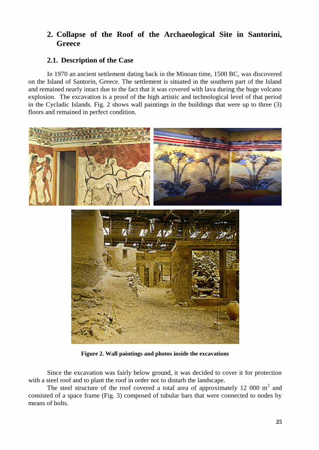
In 1970 an ancient settlement dating back in the Minoan time, 1500 BC, was discovered
on the Island of Santorin, Greece. The settlement is situated in the southern part of the Island
and remained nearly intact due to the fact that it was covered with lava during the huge volcano
explosion. The excavation is a proof of the high artistic and technological level of that period
in the Cycladic Islands. Fig. 2 shows wall paintings in the buildings that were up to three (3)
floors and remained in perfect condition.
Figure 2. Wall paintings and photos inside the excavations
Since the excavation was fairly below ground, it was decided to cover it for protection
with a steel roof and to plant the roof in order not to disturb the landscape.
The steel structure of the roof covered a total area of approximately 12 000 m2 and
consisted of a space frame (Fig. 3) composed of tubular bars that were connected to nodes by
means of bolts.
26
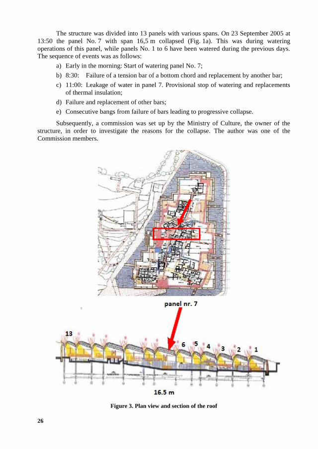
The structure was divided into 13 panels with various spans. On 23 September 2005 at
13:50 the panel No. 7 with span 16,5 m collapsed (Fig. 1a). This was during watering
operations of this panel, while panels No. 1 to 6 have been watered during the previous days.
The sequence of events was as follows:
a) Early in the morning: Start of watering panel No. 7;
b) 8:30: Failure of a tension bar of a bottom chord and replacement by another bar;
c) 11:00: Leakage of water in panel 7. Provisional stop of watering and replacements
of thermal insulation;
d) Failure and replacement of other bars;
e) Consecutive bangs from failure of bars leading to progressive collapse.
Subsequently, a commission was set up by the Ministry of Culture, the owner of the
structure, in order to investigate the reasons for the collapse. The author was one of the
Commission members.
Figure 3. Plan view and section of the roof

27
2.2. Investigation of the Loads and the Structure
In order to investigate the case, the actual loads on the roof were determined. They were
composed of the, known, self-weights of the structure and the covering panels, as well as of the
self-weight of the soil that was determined by measuring its depth (Fig. 4) and its density in
fully saturated conditions.
Figure 4. Measuring the depth of the soil
The measurements showed that the actual weight of the soil was much higher than its
nominal design values, assumed in the structural design (Fig. 5). This was due to the fact that
both its depth and its specific weight were much higher than those anticipated in the design
phase.
Figure 5. Comparison of actual vs. assumed in design soil weight

28
In addition, specimens were taken from bars, bolts and nodes to determine the actual
material properties and to investigate the behaviour of the bars under compression and tension
(Fig. 6). It was found out that the material was in accordance with the specifications assumed
in the structural design.
Figure 6. Buckled bars of the structure
3. Numerical Simulation
3.1. Numerical Models for Structural Members
a)
b)
Figure 7. Bars in the actual structure (a) and their models (b)
29
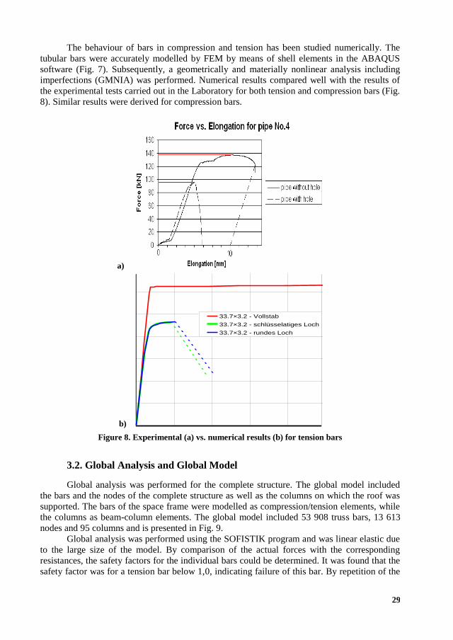
The behaviour of bars in compression and tension has been studied numerically. The
tubular bars were accurately modelled by FEM by means of shell elements in the ABAQUS
software (Fig. 7). Subsequently, a geometrically and materially nonlinear analysis including
imperfections (GMNIA) was performed. Numerical results compared well with the results of
the experimental tests carried out in the Laboratory for both tension and compression bars (Fig.
8). Similar results were derived for compression bars.
a)
b)
33.7×3.2 - Εφελκυσμός
0
20
40
60
80
100
120
140
0,0% 0,1% 0,2% 0,3% 0,4% 0,5%
Dehnung [%]
Last
[kN
]
33.7×3.2 - Vollstab
33.7×3.2 - schlüsselatiges Loch
33.7×3.2 - rundes Loch
Figure 8. Experimental (a) vs. numerical results (b) for tension bars
3.2. Global Analysis and Global Model
Global analysis was performed for the complete structure. The global model included
the bars and the nodes of the complete structure as well as the columns on which the roof was
supported. The bars of the space frame were modelled as compression/tension elements, while
the columns as beam-column elements. The global model included 53 908 truss bars, 13 613
nodes and 95 columns and is presented in Fig. 9.
Global analysis was performed using the SOFISTIK program and was linear elastic due
to the large size of the model. By comparison of the actual forces with the corresponding
resistances, the safety factors for the individual bars could be determined. It was found that the
safety factor was for a tension bar below 1,0, indicating failure of this bar. By repetition of the

30
analysis with this bar missing, safety factors below 1,0 were determined for other bars,
indicating progressive collapse. This was promoted also by the fact that the bars had no
ductility due to the provision of large holes opened in order to pass the connection bolts
through them (Fig. 7). More information is provided in [1].
Figure 9. Plan view of the global model
Finally, the reasons of failure are summarized as following:
1. Severe overloading due to higher depth and higher density of soil;
2. Development of substantial restraint forces due to structural imperfections;
3. Reduction of resistance due to slotted holes;
4. Reduction of ductility due to large holes and small material overstrength.
4. List of Actions and Lessons
The list of actions when performing forensic research on structural failures may be
recommended as follows:
On-site documentation: Visit the site, take photos and observe closely the
debris;
Historical data: History of the structure during the construction and operation
period;

31
Event: Information, preferably by eyewitnesses, on the conditions at the time of
the event and possibly the failure progress;
Survey of existing design and construction documents;
Performance of experimental tests for materials and components;
Loads: Environmental conditions, live loads and other actions at the time of the
event;
New design: Independent structural design with the loads at the time of the
event. Focus on the area and elements of collapse;
Technical report: Includes all documentation, tests and calculations and
concludes with the causes of failure not forgetting that they are in most cases
more than one.
The examination of a number of cases by the author leads to following lessons in order
to avoid structural failure:
1. Structures must be properly designed, executed, operated and maintained;
2. Structural designs must be appropriately checked and certified;
3. Fabrication and erection must be appropriately checked and certified according
to the quality control plan.
5. Ethics
When performing Forensic Engineering services some ethical considerations should be
followed that might be summarized as follows:
Perform services only in areas of competence. Call other specialists if necessary;
Never compromise your personal integrity;
Treat information given by your client confidentially;
Be objective in your reports or oral statements and make a distinction between
facts and opinions.
REFERENCES
1. Vayas, I., Ermopoulos, J., Thanopoulos, P. Versagen des Daches der archäologischen
Stätte in Santorin/Griechenland. // Stahlbau, 2006, 75(5): 349-356.
2. Penelis, G et al. 2006, Report of the Committee for the Clarification of the Causes of
a Part of the Roof of the Archaeological Site in Santorini.


![Forensic Engineering Equals Detective Engineering … Engineering ... Forensic Engineering Equals Detective Engineering (1) [Compatibility Mode] Author: Owner Created Date: 11/19/2013](https://img.pdfslide.us/doc/110x75/5b0c643d7f8b9af65e8bfc74/forensic-engineering-equals-detective-engineering-engineering-forensic-engineering.jpg)