Embed Size (px)
Citation preview
6R80
FORD 6R80 UPDATES• Presented by:• David Chalker• ATRA Technical Advisor

6R80
Welcome To Today’s Presentation
Sponsored By:
6R80

6R80

6R80
Any Questions Or Comments Please Send Emails To [email protected]
Any Questions That You May Have During The Webinar Please Feel Free
To Text Them In At Any Time
6R80
THE HANDOUT IS NOW AVAILABLE AS A DOWNLOAD. IF YOU DO NOT HAVE THE HANDOUT SIMPLY CLICK ON THE ICON IN THE QUESTION BOX
TO DOWNLOAD THE HANDOUT NOW
6R80
FORD 6R80 UPDATES
6R80
Ford began using the ZF6HP26 transmission in the 2005 Ford Expedition and Lincoln Navigator with the 5.4L engine. In subsequent years, this transmission, known as the 6R60/75/80, began showing up in Explorer, Mountaineer, F150, and Mustang vehicles. The 6R60/75/80 automatic transmission provides six forward speeds using these components:
• a four-element torque converter which houses a multi-disc lockup clutch• 3 driving clutches — clutches A, B, and E• 2 brake clutches — clutches C and D• a Lepelletier planetary geartrain and a valve body assembly fitted with a Mechatronic control unit.
The mechatronic control unit commands all hydraulic functions through the electronic shift solenoids, to control garage shifting, shift timing, and shift feel. The Mechatronic module also includes an output shaft speed sensor (OSS), a turbine shaft speed sensor (TSS), a transmission fluid temperature sensor (TFT), and a transmission range sensor (TR).
In 2011, Ford revamped its engine lineup for the F150 series vehicles. The familiar 4.6L and 5.4L engines were replaced with four new engines.
• 3.5L Turbo V6• 3.7L Ti-VCT V6 with twin independent variable camshaft timing• 5.0L V8• 6.2L V8
In addition to the new engine line-up, new features and changes were made to the 6R80 transmission. To enhance customer satisfaction, performance and durability. In this webinar, we will go into those important updates that have been made for this 6-speed transmission.
6R80
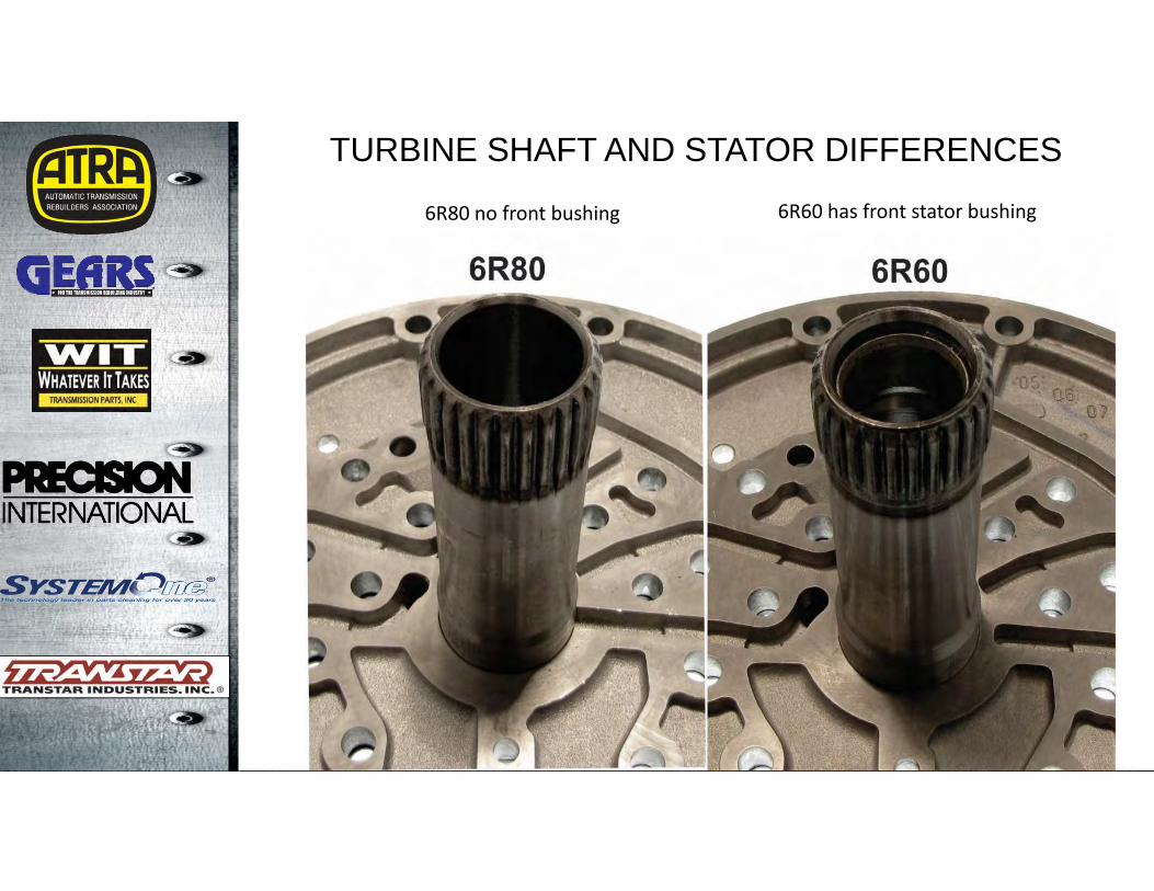
TURBINE SHAFT AND STATOR DIFFERENCES
6R60 has front stator bushing6R80 no front bushing
6R80
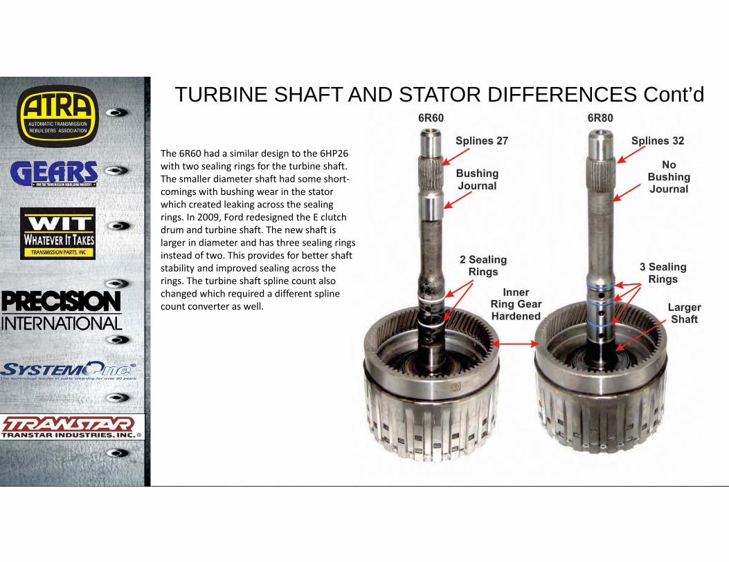
The 6R60 had a similar design to the 6HP26 with two sealing rings for the turbine shaft. The smaller diameter shaft had some short‐comings with bushing wear in the stator which created leaking across the sealing rings. In 2009, Ford redesigned the E clutch drum and turbine shaft. The new shaft is larger in diameter and has three sealing rings instead of two. This provides for better shaft stability and improved sealing across the rings. The turbine shaft spline count also changed which required a different spline count converter as well.
TURBINE SHAFT AND STATOR DIFFERENCES Cont’d
6R80
D1 RegulatorValve SpringEliminated
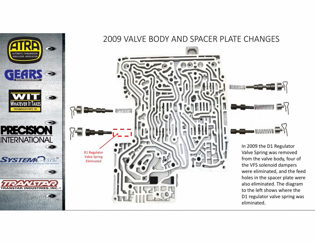
In 2009 the D1 Regulator Valve Spring was removed from the valve body, four of the VFS solenoid dampers were eliminated, and the feed holes in the spacer plate werealso eliminated. The diagram to the left shows where the D1 regulator valve spring was eliminated.
2009 VALVE BODY AND SPACER PLATE CHANGES
6R80
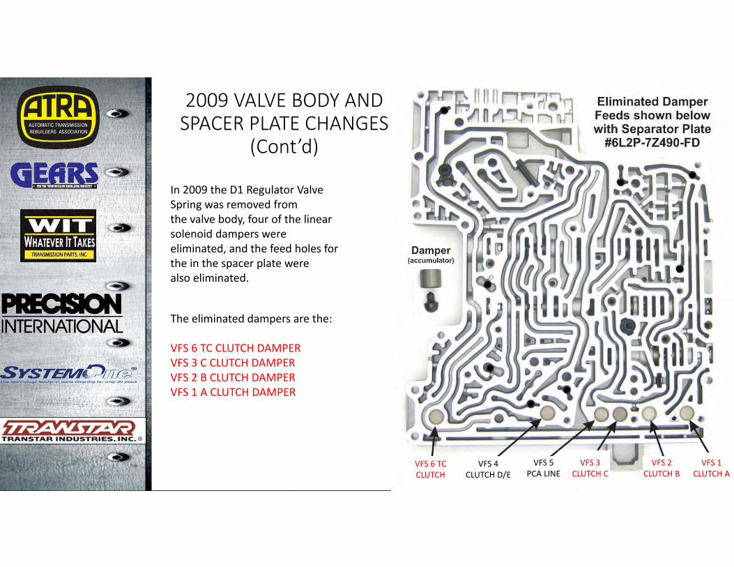
2009 VALVE BODY AND SPACER PLATE CHANGES
(Cont’d)
In 2009 the D1 Regulator Valve Spring was removed fromthe valve body, four of the linear solenoid dampers were eliminated, and the feed holes for the in the spacer plate werealso eliminated.
The eliminated dampers are the:
VFS 6 TC CLUTCH DAMPERVFS 3 C CLUTCH DAMPERVFS 2 B CLUTCH DAMPERVFS 1 A CLUTCH DAMPER
VFS 6 TCCLUTCH
VFS 4CLUTCH D/E
VFS 5PCA LINE
VFS 3CLUTCH C
VFS 2CLUTCH B
VFS 1CLUTCH A
6R80
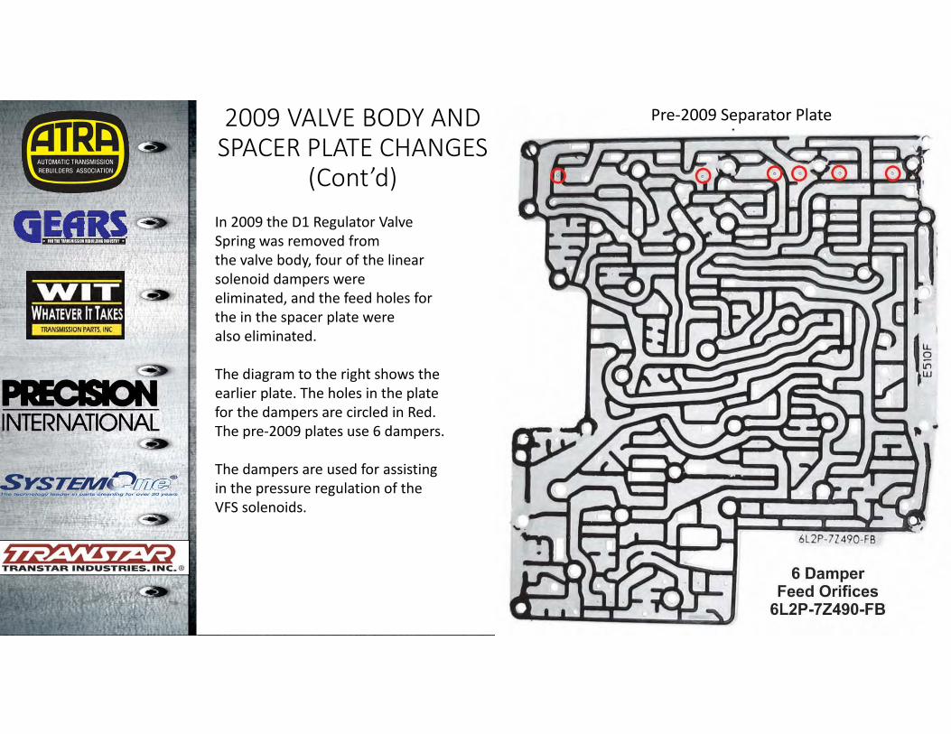
Pre‐2009 Separator Plate2009 VALVE BODY AND SPACER PLATE CHANGES
(Cont’d)In 2009 the D1 Regulator Valve Spring was removed fromthe valve body, four of the linear solenoid dampers were eliminated, and the feed holes for the in the spacer plate werealso eliminated.
The diagram to the right shows the earlier plate. The holes in the plate for the dampers are circled in Red. The pre‐2009 plates use 6 dampers.
The dampers are used for assisting in the pressure regulation of the VFS solenoids.
6R80
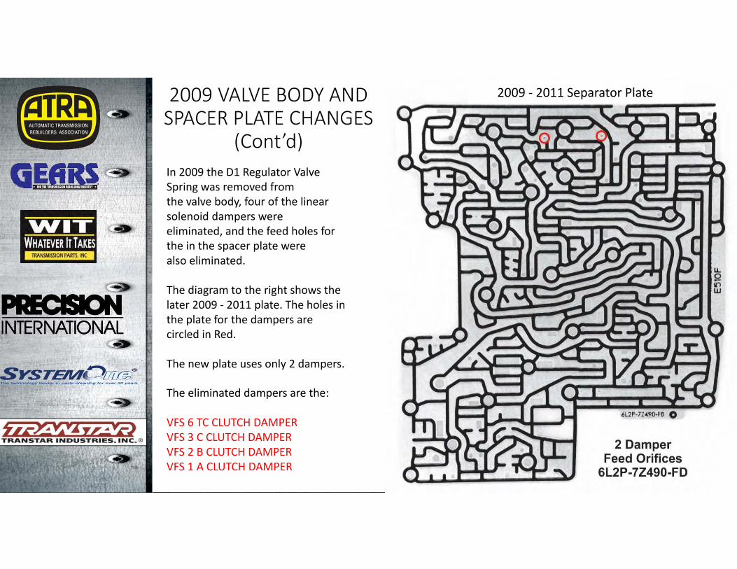
2009 ‐ 2011 Separator Plate
The eliminated dampers are the:
VFS 6 TC CLUTCH DAMPERVFS 3 C CLUTCH DAMPERVFS 2 B CLUTCH DAMPERVFS 1 A CLUTCH DAMPER
2009 VALVE BODY AND SPACER PLATE CHANGES
(Cont’d)In 2009 the D1 Regulator Valve Spring was removed fromthe valve body, four of the linear solenoid dampers were eliminated, and the feed holes for the in the spacer plate werealso eliminated.
The diagram to the right shows the later 2009 ‐ 2011 plate. The holes in the plate for the dampers are circled in Red.
The new plate uses only 2 dampers.
6R80
ONE‐WAY CLUTCH ADDED
• The addition of the one‐way clutch required multiple changes to the transmission case, the C and D support and all of its components, and the rear planetary assembly. Changes were also made in the valve body, the molded lead frame, and the wiring harness, plus changes to the computer strategy for control of the D clutch. The TCM was removed from inside the transmission on the molded lead‐frame and was incorporated into the PCM.
• In previous models there were a number of complaints of harsh 1‐2 and 2‐1 shifts which Ford tried to solve by updating PCM/TCM calibration. In this unit, Ford added a one‐way clutch to the rear planetary assembly to provide smoother transitions from 1‐2 and 2‐1. Adding the one‐way clutch required changing the strategy for application of the D clutch and solenoid D. In previous models without the one‐way clutch, the D clutch applies throughout first gear. In the 2011‐later models with the one‐way clutch, the D clutch only applies until about 3 MPH; then the D clutch releases. In earlier models without the one‐way clutch, SSD or VFS4 D/E clutch solenoid didn’t energize until 2nd gear. In the 2011‐later models with the one‐way clutch, the solenoid turns on at about 3 MPH.
• The remainder of this webinar will be geared to the changes that occurred with the addition of the one‐way clutch in the 6R80.
6R80
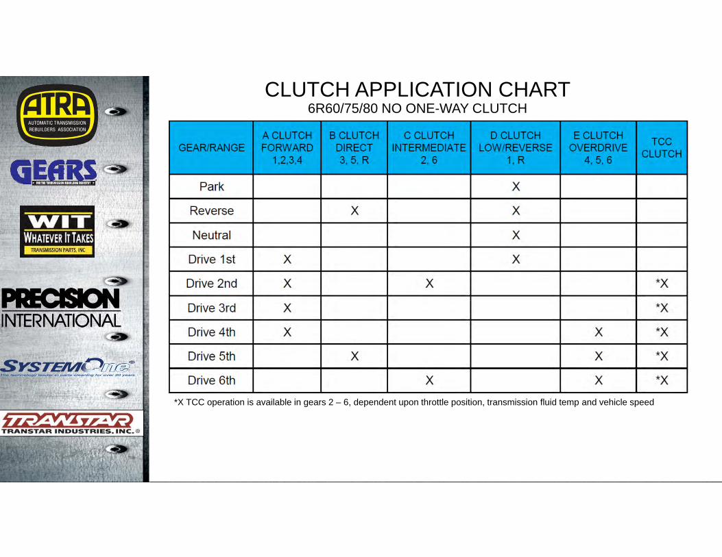
CLUTCH APPLICATION CHART6R60/75/80 NO ONE-WAY CLUTCH
*X TCC operation is available in gears 2 – 6, dependent upon throttle position, transmission fluid temp and vehicle speed
6R80
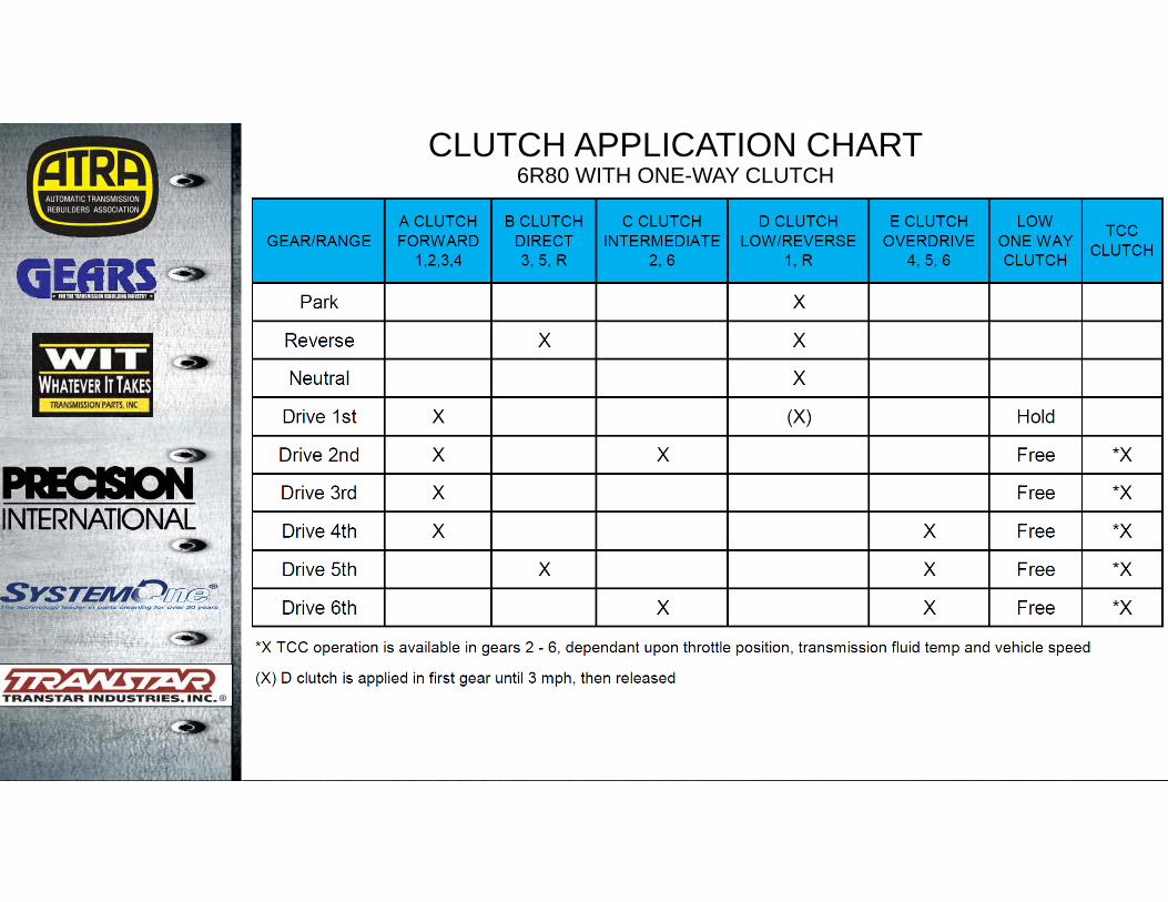
CLUTCH APPLICATION CHART6R80 WITH ONE-WAY CLUTCH
6R80
ONE WAY CLUTCH ADDED (Cont’d)
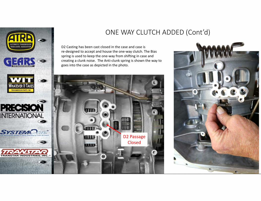
D2 Casting has been cast closed in the case and case isre‐designed to accept and house the one‐way clutch. The Bias spring is used to keep the one‐way from shifting in case and creating a clunk noise. The Anti‐clunk spring is shown the way to goes into the case as depicted in the photo.
D2 PassageClosed
6R80
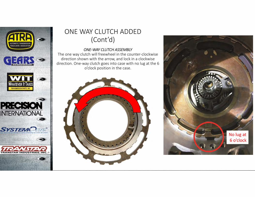
ONE‐WAY CLUTCH ASSEMBLYThe one way clutch will freewheel in the counter‐clockwise direction shown with the arrow, and lock in a clockwise
direction. One‐way clutch goes into case with no lug at the 6 o’clock position in the case.
No lug at6 o’clock
ONE WAY CLUTCH ADDED (Cont’d)

6R80
ONE WAY CLUTCH ADDED (Cont’d)
Insert the springs and locks (10 required) into the one‐way clutch housing, hold the springs and locks in place using Transgel®. This will keep the springs compressed when assembling the one‐way clutch
and will make it easier to assemble.
6R80
ONE WAY CLUTCH ADDED (Cont’d)
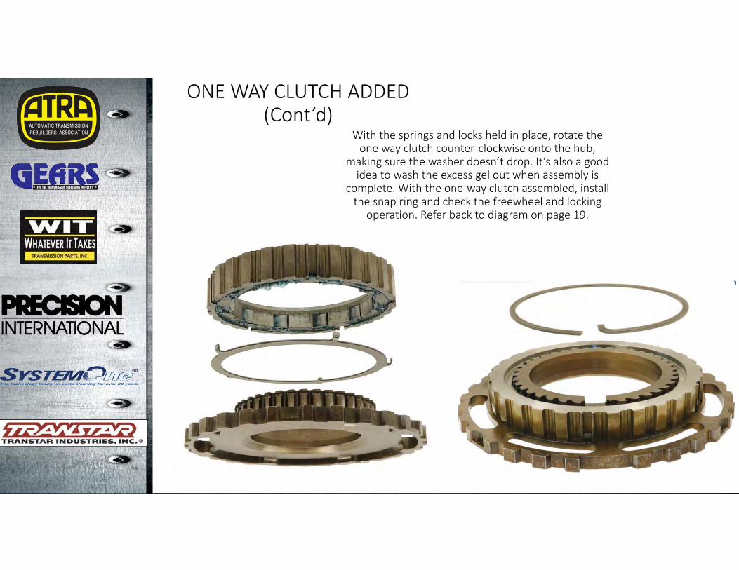
With the springs and locks held in place, rotate the one way clutch counter‐clockwise onto the hub,
making sure the washer doesn’t drop. It’s also a good idea to wash the excess gel out when assembly is
complete. With the one‐way clutch assembled, install the snap ring and check the freewheel and locking
operation. Refer back to diagram on page 19.
6R80
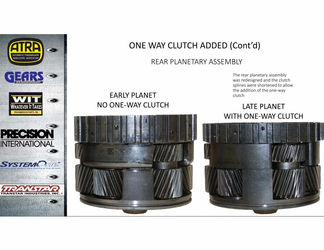
REAR PLANETARY ASSEMBLY
EARLY PLANETNO ONE‐WAY CLUTCH LATE PLANET
WITH ONE‐WAY CLUTCH
ONE WAY CLUTCH ADDED (Cont’d)
The rear planetary assembly was redesigned and the clutch splines were shortened to allow the addition of the one‐way clutch
6R80
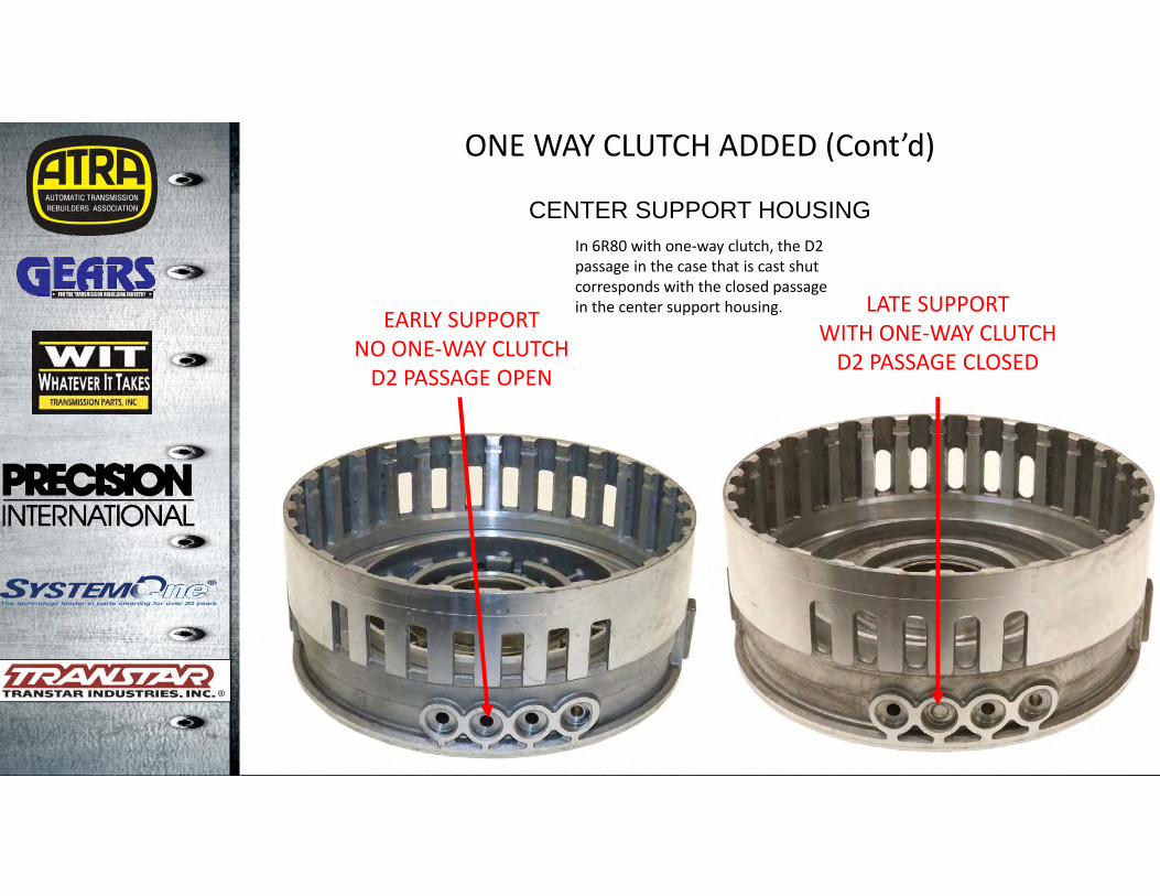
CENTER SUPPORT HOUSING
LATE SUPPORTWITH ONE‐WAY CLUTCHD2 PASSAGE CLOSED
EARLY SUPPORTNO ONE‐WAY CLUTCHD2 PASSAGE OPEN
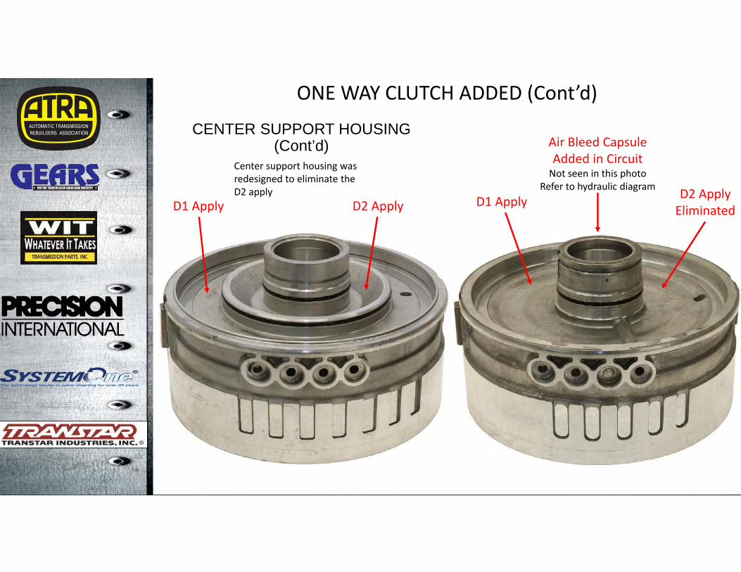
In 6R80 with one‐way clutch, the D2 passage in the case that is cast shut corresponds with the closed passage in the center support housing.
ONE WAY CLUTCH ADDED (Cont’d)
6R80
Center support housing was redesigned to eliminate theD2 apply
D1 Apply D2 Apply D1 Apply D2 ApplyEliminated
Air Bleed CapsuleAdded in CircuitNot seen in this photo
Refer to hydraulic diagram
CENTER SUPPORT HOUSING (Cont’d)
ONE WAY CLUTCH ADDED (Cont’d)
6R80
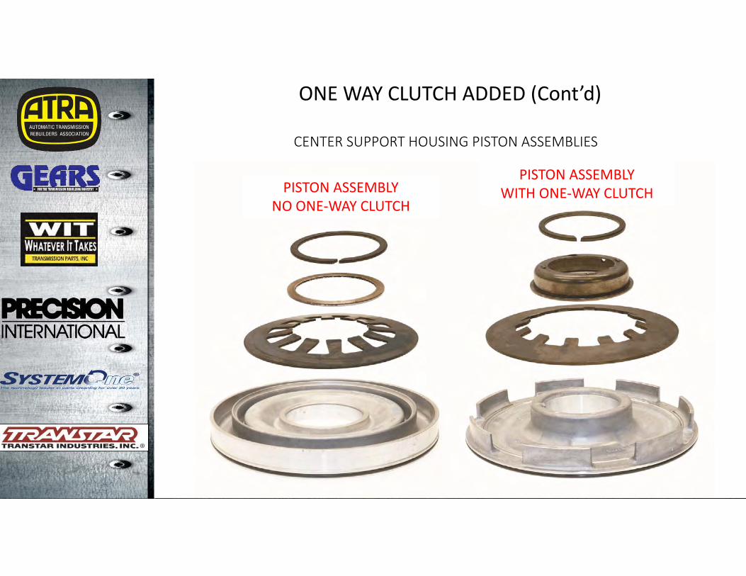
CENTER SUPPORT HOUSING PISTON ASSEMBLIES
PISTON ASSEMBLYNO ONE‐WAY CLUTCH
PISTON ASSEMBLYWITH ONE‐WAY CLUTCH
ONE WAY CLUTCH ADDED (Cont’d)
6R80
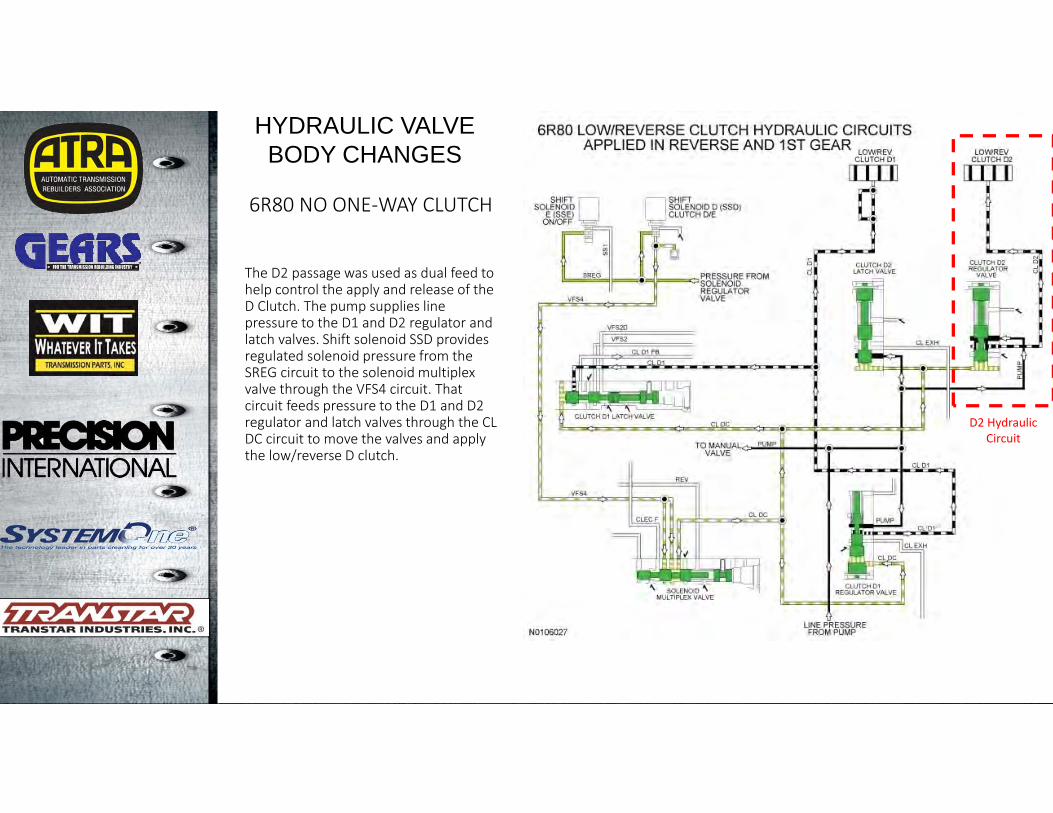
6R80 NO ONE‐WAY CLUTCH
HYDRAULIC VALVE BODY CHANGES
The D2 passage was used as dual feed to help control the apply and release of the D Clutch. The pump supplies line pressure to the D1 and D2 regulator and latch valves. Shift solenoid SSD provides regulated solenoid pressure from the SREG circuit to the solenoid multiplex valve through the VFS4 circuit. That circuit feeds pressure to the D1 and D2 regulator and latch valves through the CL DC circuit to move the valves and apply the low/reverse D clutch.
D2 HydraulicCircuit
6R80
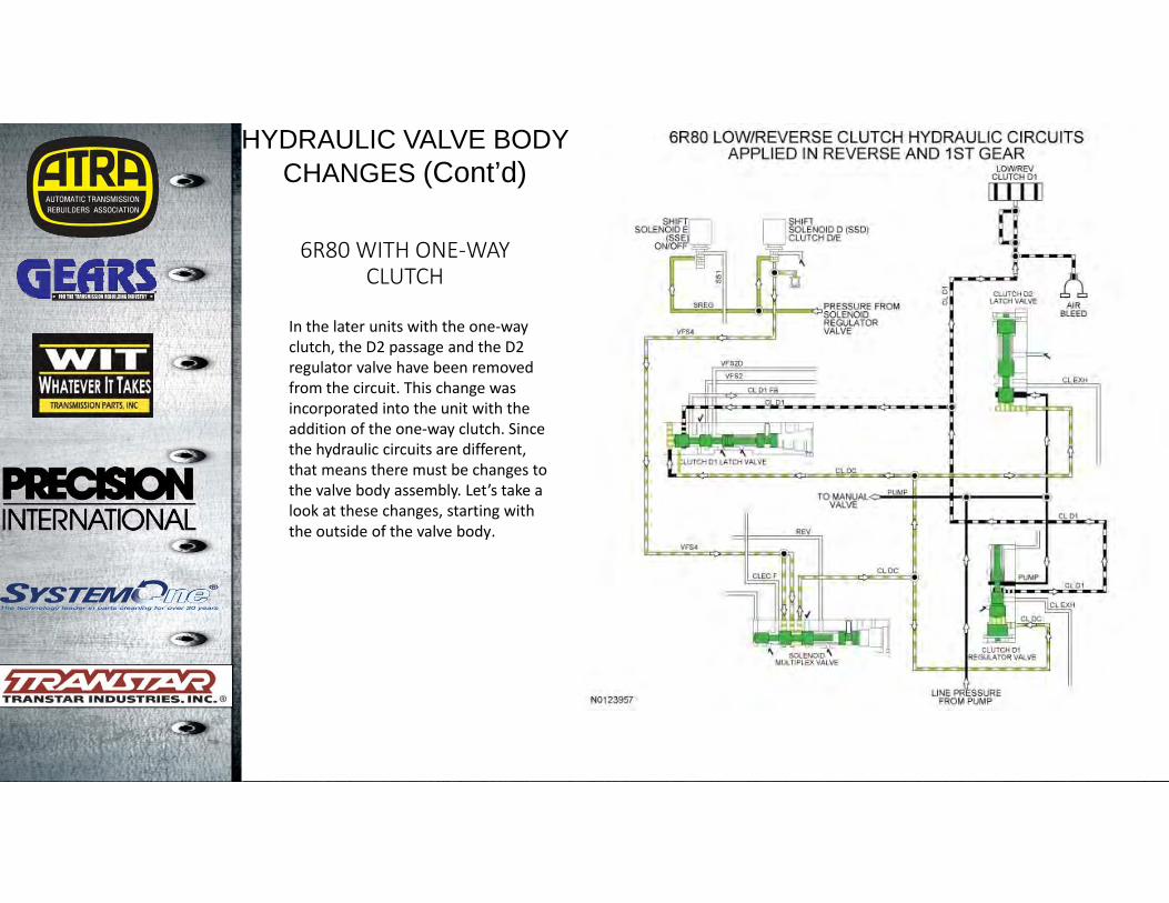
6R80 WITH ONE‐WAY CLUTCH
HYDRAULIC VALVE BODY CHANGES (Cont’d)
In the later units with the one‐way clutch, the D2 passage and the D2 regulator valve have been removed from the circuit. This change was incorporated into the unit with the addition of the one‐way clutch. Since the hydraulic circuits are different, that means there must be changes to the valve body assembly. Let’s take a look at these changes, starting with the outside of the valve body.
6R80
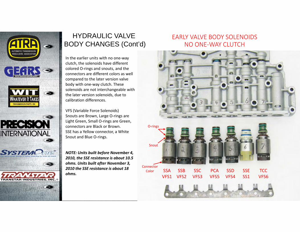
EARLY VALVE BODY SOLENOIDS NO ONE‐WAY CLUTCH
HYDRAULIC VALVEBODY CHANGES (Cont’d)
SSAVFS1
SSBVFS2
SSCVFS3
PCAVFS5
SSDVFS4
SSESS1
TCCVFS6
In the earlier units with no one‐way clutch, the solenoids have different colored O‐rings and snouts, and the connectors are different colors as well compared to the later version valve body with one‐way clutch. These solenoids are not interchangeable with the later version solenoids, due to calibration differences.
VFS (Variable Force Solenoids)Snouts are Brown, Large O‐rings are Light Green, Small O‐rings are Green, connectors are Black or Brown.SSE has a Yellow connector, a White Snout and Blue O‐rings.
NOTE: Units built before November 4, 2010, the SSE resistance is about 10.5 ohms. Units built after November 3, 2010 the SSE resistance is about 18 ohms.
O‐rings
Snout
ConnectorColor

6R80
LATE VALVE BODY SOLENOIDSWITH ONE‐WAY CLUTCH
In the earlier units with no one‐way clutch, the solenoids have different colored O‐rings and snouts, and the connectors are different colors as well. These solenoids are not interchangeable with the earlier version solenoids, due to calibration differences.
VFS (Variable Force Solenoids)The Normally Vented Solenoids (VFS 1, VFS 3, and VFS 6 each have a brown snout and the O‐rings are Green and Red.The Normally Applied solenoids (VFS 2, VFS 4, and VFS 5 have a Black snout and the O‐rings are Orange and Red.SSE has a White snout and Blue O‐rings.
NOTE: Units built before November 4, 2010, the SSE resistance is about 10.5 ohms. Units built after November 3, 2010 the SSE resistance is about 18 ohms.
SSAVFS1
SSBVFS2
SSCVFS3
PCAVFS5
SSDVFS4
SSESS1
TCCVFS6
HYDRAULIC VALVEBODY CHANGES (Cont’d)
6R80
HYDRAULIC VALVEBODY CHANGES (Cont’d)
4
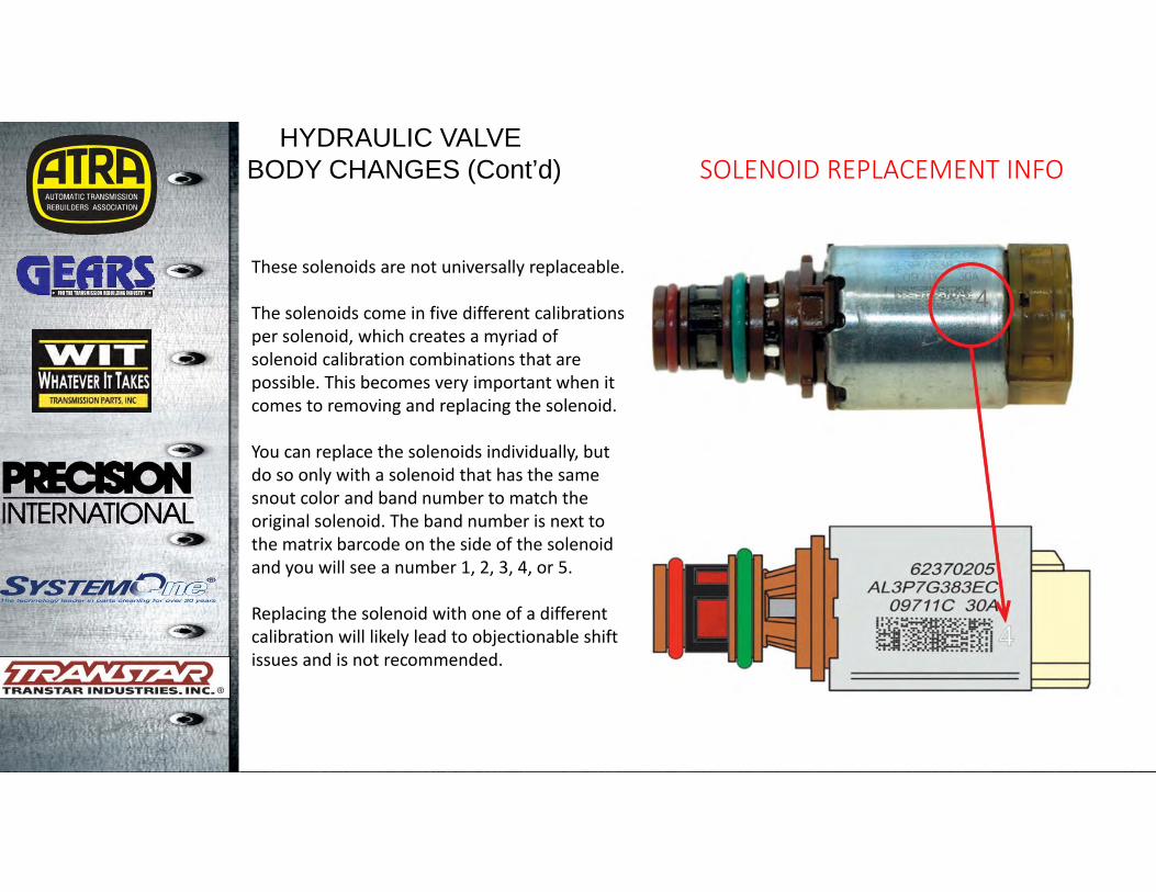
SOLENOID REPLACEMENT INFO
These solenoids are not universally replaceable.
The solenoids come in five different calibrations per solenoid, which creates a myriad of solenoid calibration combinations that are possible. This becomes very important when it comes to removing and replacing the solenoid.
You can replace the solenoids individually, but do so only with a solenoid that has the same snout color and band number to match the original solenoid. The band number is next to the matrix barcode on the side of the solenoid and you will see a number 1, 2, 3, 4, or 5.
Replacing the solenoid with one of a different calibration will likely lead to objectionable shift issues and is not recommended.
6R80
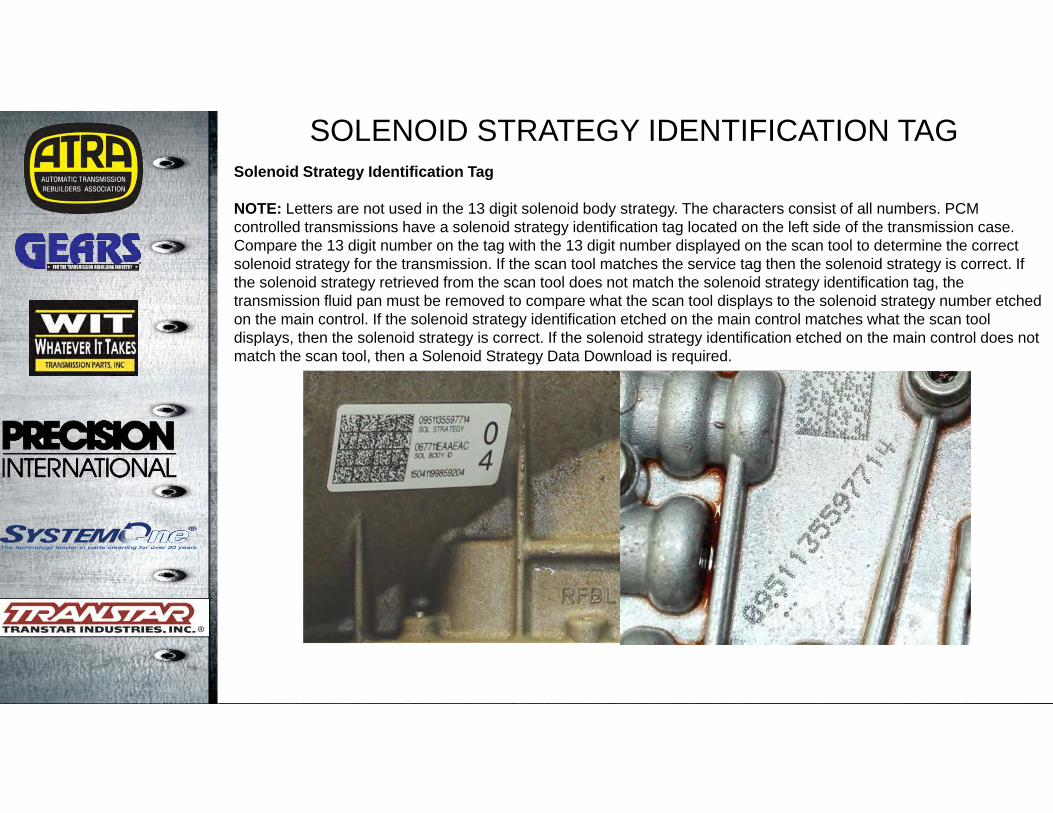
SOLENOID STRATEGY IDENTIFICATION TAGSolenoid Strategy Identification Tag
NOTE: Letters are not used in the 13 digit solenoid body strategy. The characters consist of all numbers. PCM controlled transmissions have a solenoid strategy identification tag located on the left side of the transmission case. Compare the 13 digit number on the tag with the 13 digit number displayed on the scan tool to determine the correct solenoid strategy for the transmission. If the scan tool matches the service tag then the solenoid strategy is correct. If the solenoid strategy retrieved from the scan tool does not match the solenoid strategy identification tag, the transmission fluid pan must be removed to compare what the scan tool displays to the solenoid strategy number etched on the main control. If the solenoid strategy identification etched on the main control matches what the scan tool displays, then the solenoid strategy is correct. If the solenoid strategy identification etched on the main control does not match the scan tool, then a Solenoid Strategy Data Download is required.
6R80
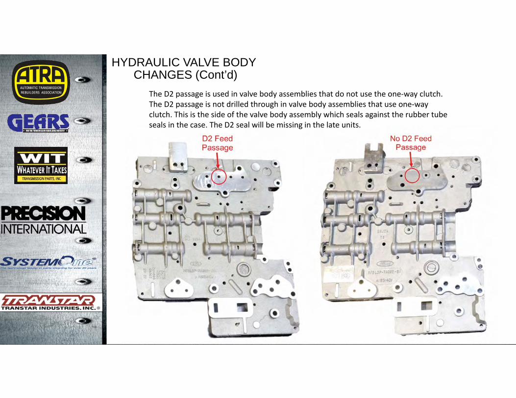
HYDRAULIC VALVE BODYCHANGES (Cont’d)
The D2 passage is used in valve body assemblies that do not use the one‐way clutch.The D2 passage is not drilled through in valve body assemblies that use one‐way clutch. This is the side of the valve body assembly which seals against the rubber tube seals in the case. The D2 seal will be missing in the late units.
6R80
HYDRAULIC VALVE BODYCHANGES (Cont’d)
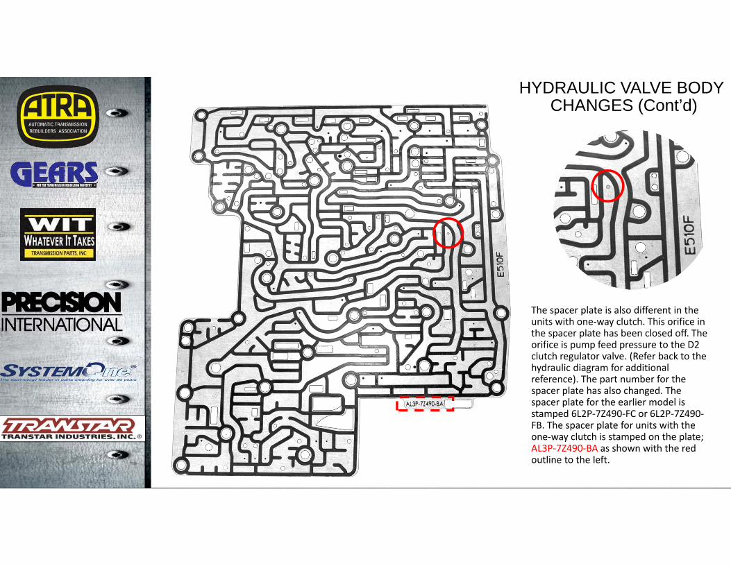
The spacer plate is also different in the units with one‐way clutch. This orifice in the spacer plate has been closed off. The orifice is pump feed pressure to the D2 clutch regulator valve. (Refer back to the hydraulic diagram for additional reference). The part number for the spacer plate has also changed. The spacer plate for the earlier model is stamped 6L2P‐7Z490‐FC or 6L2P‐7Z490‐FB. The spacer plate for units with the one‐way clutch is stamped on the plate;AL3P‐7Z490‐BA as shown with the red outline to the left.

6R80
HYDRAULIC VALVE BODYCHANGES (Cont’d)
With the D2 circuit in the transmission being eliminated, the clutch dampers were reinstalled back into the valve body assembly and the orifices in the spacer plate are again seen as shown in the diagram to the left.
6R80
HYDRAULIC VALVE BODYCHANGES (Cont’d)
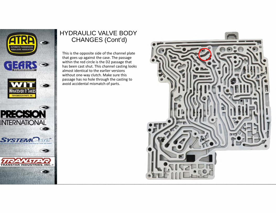
This is the opposite side of the channel plate that goes up against the case. The passage within the red circle is the D2 passage that has been cast shut. This channel casting looks almost identical to the earlier versions without one‐way clutch. Make sure this passage has no hole through the casting to avoid accidental mismatch of parts.
6R80
HYDRAULIC VALVE BODYCHANGES (Cont’d)
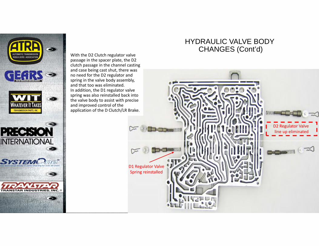
With the D2 Clutch regulator valve passage in the spacer plate, the D2 clutch passage in the channel casting and case being cast shut, there was no need for the D2 regulator and spring in the valve body assembly, and that too was eliminated. In addition, the D1 regulator valve spring was also reinstalled back into the valve body to assist with precise and improved control of the application of the D Clutch/LR Brake.
D2 Regulator Valve line up eliminated
D1 Regulator ValveSpring reinstalled
6R80
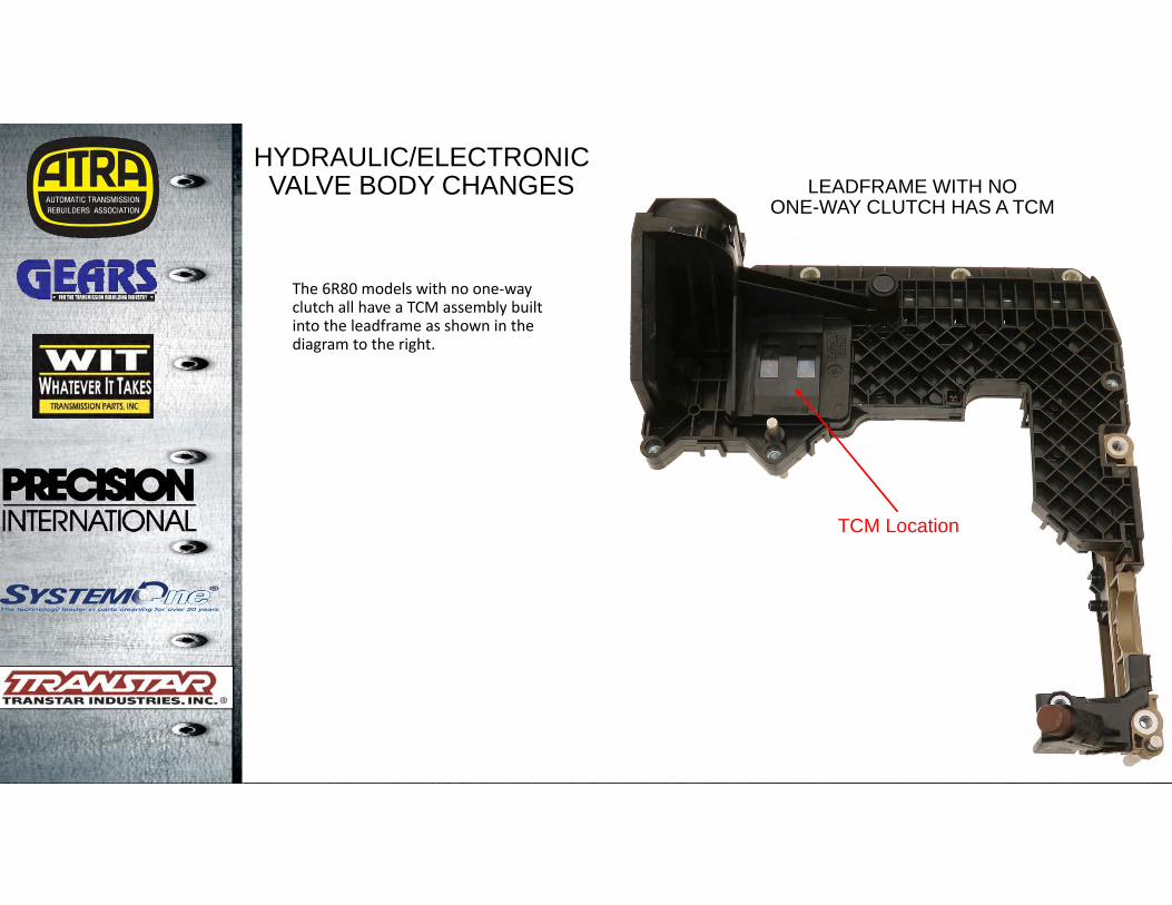
HYDRAULIC/ELECTRONIC VALVE BODY CHANGES LEADFRAME WITH NO
ONE-WAY CLUTCH HAS A TCM
TCM Location
The 6R80 models with no one‐way clutch all have a TCM assembly built into the leadframe as shown in the diagram to the right.

6R80
HYDRAULIC/ELECTRONIC VALVE BODY CHANGES
(Cont’d) LEADFRAME WITH ONE-WAY CLUTCH HAS NO TCM
TCM Removed fromleadframe assembly
The 6R80 models with one-way clutch all have the TCM eliminated from the leadframe as shown in the diagram to the right. Control over the transmission now is performed by the Powertrain Control Module. The removal of the TCM and addition of PCM control required changes and additions to the wiring harness to accommodate PCM control.As always, refer to the factory manual for wiring diagrams, as they may change from year to year and model to model.
6R80
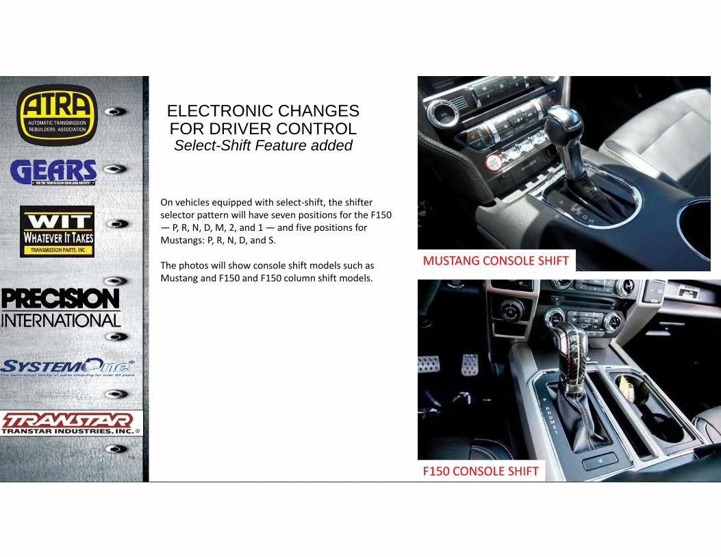
ELECTRONIC CHANGESFOR DRIVER CONTROLSelect-Shift Feature added
On vehicles equipped with select‐shift, the shifter selector pattern will have seven positions for the F150 — P, R, N, D, M, 2, and 1 — and five positions for Mustangs: P, R, N, D, and S.
The photos will show console shift models such as Mustang and F150 and F150 column shift models.
F150 CONSOLE SHIFT
MUSTANG CONSOLE SHIFT

6R80
F150 COLUMN SHIFT
In drive (D), all driving is automated and controlled by the PCM. In SelectShift (S), driver control is engaged, giving the driver shift control through a button on the shifter handle on the steering column for F150s, and on the console shifter handle for Mustangs as well as some F150 models.
The manual position lets you control shifting by pressing the + and – buttons on the shifter. In addition, you can lock out gears for driving in hilly conditions or when towing.
By selecting M (F150’s) or S (Mustang) in first gear and pressing the – button, you can lock out the higher gears, essentially turning the 6R80 into a 5‐speed, 4‐speed, or even a 3‐speed transmission.
ELECTRONIC CHANGESFOR DRIVER CONTROLSelect-Shift Feature added
(Cont’d)

6R80
Today’s Presentation
Sponsored By:
Any Questions?Thank You For
Attending