Embed Size (px)
Citation preview

American Journal of Energy Engineering 2015; 3(3): 37-45
Published online May 8, 2015 (http://www.sciencepublishinggroup.com/j/ajee)
doi: 10.11648/j.ajee.20150303.12
ISSN: 2329-1648 (Print); ISSN: 2329-163X (Online)
Forced Convection Heat Transfer Analysis through Dimpled Surfaces with Different Arrangements
Hasibur Rahman Sardar1, Abdul Razak Kaladgi
2, *
1Department of Electronics & Communication Engineering, P.A College of Engineering, Karnataka, India 2Department of Mechanical Engineering, P.A College of Engineering, Karnataka, India
Email address: [email protected] (H. R. Sardar), [email protected] (A. R. Kaladgi)
To cite this article: Hasibur Rahman Sardar, Abdul Razak Kaladgi. Forced Convection Heat Transfer Analysis through Dimpled Surfaces with Different
Arrangements. American Journal of Energy Engineering. Vol. 3, No. 3, 2015, pp. 37-45. doi: 10.11648/j.ajee.20150303.12
Abstract: Dimples play a very important role in heat transfer enhancement of electronic cooling systems, heat exchangers
etc. This work mainly deals with the experimental investigation of forced convection heat transfer over circular shaped dimples
of different diameters on a flat copper plate under external laminar flow conditions. Experimental measurements on heat
transfer characteristics of air (with various inlet flow rates) on a flat plate with dimples were conducted. From the obtained
results, it was observed that the heat transfer coefficient and Nusselt number were high for the copper plate in which the
diameter of dimples increases centrally in the direction of flow (case c) as compared to the other two cases.
Keywords: Forced Convection, Dimples, Heat Transfer, Passive Techniques
1. Introduction
There are various heat transfer applications where the use
of fluid-to-gas heat exchanger is important. The issues like
accurate heat transfer rate analysis, estimations of pressure
drops, long-term performance and economic aspect of the
equipment make the design of heat exchangers quite
complicated. Also higher performance, higher heat transfer
rate with minimum pumping power requirements are some of
the main challenges of the heat exchanger design. Therefore,
improving the heat exchanger efficiency through the
enhancement techniques resulting in a considerable reduction
in cost is one of main task faced by the engineers [1].Various
heat transfer enhancement techniques are developed and used
for heat exchanger applications over the past couple of years.
Several attempts are also made to reduce the size and cost of
the heat exchangers. Among these the passive techniques can
be considered important one because of its wide variety of
applications like in electronic cooling (heat sinks), process
industries, cooling and heating in evaporators, solar air
heaters, turbine airfoil cooling etc [2]. The main principle of
heat transfer enhancement in passive techniques is the
surface modifications such as protrusions, pin fins, and
dimples. Among these, the dimples (concavities) can be
considered special one as they not only enhance the heat
transfer rate but also produce minimum pressure drop
penalties [3]. The dimple produces vortex pairs, induces flow
separation & creates reattachment zones to increase the heat
transfer. And as they do not protrude into the flow so they
contribute less to the foam drag, to produce minimum
pressure drop penalties [4]. Another added advantage in
dimple manufacture is the removal of material which reduces
cost and weight of the equipment.
Kuethe [5] can be considered as the first person to make
dimples on flat surfaces to increase the heat transfer rate.
According to him the dimples are expected to promote
turbulent mixing in the flow, acting as vortex generator &
hence increase the heat transfer rate. Afanasyev et al [6]
carried an experimental to study the heat transfer
characteristics of flow over a flat plate having spherical
dimples and reported an increment of 30-40% in the heat
transfer rate with a minimum pressure drop. Chyu et al [7]
conducted an experiment to study local heat transfer
coefficient distribution in a channel having dimples of
spherical & tear drop type. They observed a considerable
increase in the distribution of local heat transfer coefficient
everywhere on these dimple surfaces as compared to flat
surface. Mahmood et al [8], experimentally investigated the
effect of dimples on heat transfer augmentation .They used
the flow visualization techniques and concluded that the
periodic nature of shedding off of vortices is the main cause
of enhancement of heat transfer and is much more
pronounced at the downstream rims of the dimples. Xie et al
38 Hasibur Rahman Sardar and Abdul Razak Kaladgi: Forced Convection Heat Transfer Analysis Through Dimpled
Surfaces with Different Arrangements
[9] numerically investigated the heat transfer and fluid flow
characteristics of teardrop dimple along with teardrop
protrusion having different eccentricities. They used the K-Ɛ
model to capture the turbulence effects. They concluded that
the heat transfer enhancement along with energy savings are
more in teardrop dimples as compared to flat surfaces.Farhad
sangtarash & hosseinshokuhmand [10] conducted
experimental & numerical investigation on inline &
staggered arrangement of dimples on multilouvered fins to
study the heat transfer and pressure drop characteristics of air
through these multilouvered fin banks at varying Reynolds
number. They concluded that the augumentation of heat
transfer was more in staggered arrangements as compared to
online arrangement.
From the literature above, it is abundantly clear that
dimples or vortex generators and the vortex heat transfer
enhancement (VHTE) techniques have a high potential to
increase the heat transfer rate along with the production of
lower pressure drop penalties. The other advantages are:
a. Fouling rate reduction b. Cost reduction c. weight
reduction etc [11], however, much of the research work either
experimental or numerical is on spherical dimples of uniform
diameter [7, 12]. It is also seen that most of the research is
confined to flow in the channel i.e. Internal flow, with a very
few studies on external flow [12]. So the main focus of this
experimental work is to study the effect of circular dimples
of various diameters under external laminar flow conditions
2. Experimental Setup
The prime objective of the present work was to study
experimentally the heat transfer enhancement through dimple
surfaces of different diameters on a flat plate using force
convection technique. For this to be possible we required a
forced convection setup which was fabricated as required.
The fabricated setup is shown below.
Figure 1. Experimental setup.
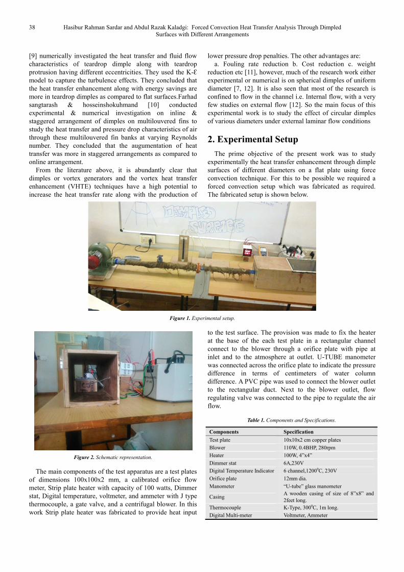
Figure 2. Schematic representation.
The main components of the test apparatus are a test plates
of dimensions 100x100x2 mm, a calibrated orifice flow
meter, Strip plate heater with capacity of 100 watts, Dimmer
stat, Digital temperature, voltmeter, and ammeter with J type
thermocouple, a gate valve, and a centrifugal blower. In this
work Strip plate heater was fabricated to provide heat input
to the test surface. The provision was made to fix the heater
at the base of the each test plate in a rectangular channel
connect to the blower through a orifice plate with pipe at
inlet and to the atmosphere at outlet. U-TUBE manometer
was connected across the orifice plate to indicate the pressure
difference in terms of centimeters of water column
difference. A PVC pipe was used to connect the blower outlet
to the rectangular duct. Next to the blower outlet, flow
regulating valve was connected to the pipe to regulate the air
flow.
Table 1. Components and Specifications.
Components Specification
Test plate 10x10x2 cm copper plates
Blower 110W, 0.4BHP, 280rpm
Heater 100W, 4”x4”
Dimmer stat 6A,230V
Digital Temperature Indicator 6 channel,12000C, 230V
Orifice plate 12mm dia.
Manometer “U-tube” glass manometer
Casing A wooden casing of size of 8”x8” and
2feet long.
Thermocouple K-Type, 3000C, 1m long.
Digital Multi-meter Voltmeter, Ammeter

American Journal of Energy Engineering 2015; 3(3): 37-45 39
3. Results and Discussion
Experiments were conducted on copper test plates with
circular dimples of different diameters. The dimples were
arranged in a staggered fashion with different arrangements
like:
Case a. Gradual Increase in the diameter of dimples in the
left & right columns of the plate in the direction flow.
Case b. Gradual Decrease in the diameter of dimples in the
left & right columns of the plate in the directionflow (reverse
case).
Case c. centrallyincreasing the diameter of dimples in the
direction flow& maintaining the left & right columnwith
constant diameter dimples.
The data obtained were used to find heat transfer
parameters like Nusselt number, heat transfer coefficient, and
heat transfer rate. And the experimental findings have been
plotted in the form of graphs, mainly
� Nusselt number(Nu) vs Reynolds number(Re)
� Heat transfer coefficient(h) vs Reynolds number(Re)
� Heat transfer rate Q vs Reynolds number(Re)
Figure 3. Variation of Nusselt number with Reynolds number(case.a).
Figure 4. Variation of Nusselt number with Reynolds number(case.b.).

40 Hasibur Rahman Sardar and Abdul Razak Kaladgi: Forced Convection Heat Transfer Analysis Through Dimpled
Surfaces with Different Arrangements
Figure 5. Variation of Nusselt number with Reynolds number(case.c.).
Figure 3, 4, 5 shows variation of Nusselt number ‘Nu’ with
Reynolds number for the three cases considered. It is obvious
that the ‘Nu’ increases as Reynolds number increases due to
direct flow impingement on the downstream boundary and
strengthened flow mixing by vortices at the downstream
[3,13]. The formation of vortex pairs which are periodically
shed off from the dimples, a large up wash regions with
somefluids coming out from the central regions of the
dimples, from vortex pairs & near dimple diagonals are the
main causes of enhancement of Nusselt number & is more
pronounced near the downstream rims of the dimples [8].It
can also be seen that the variation in the Nusselt number is
gradual with Reynolds number as expected [14, 15].
Figure 6. Variation of Heat transfer coefficient with Reynolds number(case.a.).

American Journal of Energy Engineering 2015; 3(3): 37-45 41
Figure 7. Variation of Heat transfer coefficient with Reynolds number(case.b.).
Figure 8. Variation of Heat transfer coefficient with Reynolds number(case.c.).
Figure 6, 7, 8 shows the variation of heat transfer
coefficient ‘h’ with Reynolds number ‘Re’ for the various
cases considered. It is obvious that ‘h’ increases with ‘Re’ as
expected because the development of the thermal boundary
layer is delayed or disrupted & hence enhances the local heat
transfer in the reattachment region and wake region and
increases the heat transfer coefficient [3].

42 Hasibur Rahman Sardar and Abdul Razak Kaladgi: Forced Convection Heat Transfer Analysis Through Dimpled
Surfaces with Different Arrangements
Figure 9. Variation of Heat transfer rate with Reynolds number(case.a.).
Figure 10. Variation of Heat transfer rate with Reynolds number(case.b.).

American Journal of Energy Engineering 2015; 3(3): 37-45 43
Figure 11. Variation of Heat transfer rate with Reynolds number(case.c.).
Figure 9, 10, 11 shows variation of Heat transfer rate ‘Q’
with Reynolds number ‘Re’ for the various cases considered.
It can be seen that again ‘Q’ increases as ‘Re’ increases in all
the three cases. It can also be seen that ‘Q’ is very much
higher for case c(dimples diameter decreasing centrally)
because of increased flow area as compared to the other two
cases. It can also be seen that for high Reynolds number the
‘Q’ curve for case c is higher than the curve of case b & case
c. Hence it can be concluded that case c helps in better
enhancing the heat transfer compared to case a & case b.
Figure 12. Variation of Nusselt number with Reynolds number.
Figure 12 shows comparison of Nusselt number ‘Nu’ with
Reynolds number ‘Re’ for the all the three cases considered.
It can be seen that ‘Nu’ increases as ‘Re’ increases in all the
three cases. It can also be seen that the variation for the first
two cases is very less compared to the third case may be due
the fact that the dimple diameter is not increased or decreased

44 Hasibur Rahman Sardar and Abdul Razak Kaladgi: Forced Convection Heat Transfer Analysis Through Dimpled
Surfaces with Different Arrangements
centrally where the pronounce effect of heat transfer will occur so the variation is negligibly small.
Figure 13. Variation of Heat transfer coefficient with Reynolds number.
Figure 13 shows the comparison of the variation of heat
transfer coefficient ‘h’ with Reynolds number ‘Re’ for the
various cases considered. It is obvious that ‘h’ increases with
‘Re’ as expected and it is also observed that heat transfer
coefficient is high for the third case (case of dimple diameter
decreasing centrally) due to higher heat transfer rate
occurring at the central region where the fluid flow rate is
highest compared to other two cases.
Figure 14. Variation of Heat transfer rate with Reynolds number.
Figure 14 showsthe variation of Heat transfer rate ‘Q’ with
Reynolds number ‘Re’ for the various cases considered. It
can be seen that again ‘Q’ increases as ‘Re’ increases in all
the three cases. It can also be seen that ‘Q’ is very much

American Journal of Energy Engineering 2015; 3(3): 37-45 45
lower for case b & is highest for case c because of increased
flow rate as compared to the other two cases. It can also be
seen that for high Reynolds number the ‘Q’ curve for case c
is higher than the curve of case b & case c. Hence it can be
concluded that case c helps in better enhancing the heat
transfer compared to case a & case b.
4. Conclusion
In this experimental work an investigation of the effect of
air flow over a flat plate with different diameter dimples on
the flat plate is carried out. The main conclusions of the work
were:
� Nusselt number increases with Reynolds number for all
the three cases of dimple arrangement considered due to
direct flow impingement on the downstream boundary
and strengthened flow mixing by the vortices at the
downstream.
� Case ‘c’ dimple arrangement has highest Nusselt
number because of the strong flow impingement on the
upstream side of these dimples. Case a & b dimple
arrangement gives nearly the same value of Nusselt
number.
� Heat transfer coefficient increases with Reynolds
number for all the three cases of dimples arrangement
considered due to the disruption of the thermal
boundary layer development & hence enhance the local
heat transfer in the reattachment and wake regions.
� Case ‘c’ dimple arrangement gives slightly higher value
of heat transfer coefficient as compared to case ‘a’ & ‘b’
dimples.
� Case ‘c’ dimple arrangement has better heat transfer
enhancing capacity as compared to case ‘a’ & ‘b’
because of the increased flow rate in this type ofdimple
arrangement. However, the Augmentation depends on
the configuration [12].
References
[1] Dewan, A., Mahanta, P., Raju,K.S., and Kumar.P.S.,Review of passive heat transfer augmentation techniques. Proc. Instn Mech. Engrs, Part A: J. Power and Energy, Vol. 218, pp. 509–527, 2004.
[2] Liu ,S, and Sakr ,M.A., comprehensive review on passive heat transfer enhancements in pipe exchangers. Renewable and Sustainable Energy Reviews, Vol.19 pp. 64–81, 2013.
[3] Zhang, D., Zheng, L., Xie, G., and Xie, Y.,An Experimental Study on Heat Transfer enhancement of Non-Newtonian Fluid in a Rectangular Channel with Dimples/Protrusions, Transactions of the ASME, Vol. 136, pp.021005-10, 2014.
[4] Beves, C.C., Barber, T.J., and Leonardi,E., An Investigation of Flow over Two-Dimensional Circular Cavity. In 15th Australasian Fluid Mechanics Conference, the University of Sydney, Australia, pp.13-17, 2004.
[5] Kuethe A. M., Boundary Layer Control of Flow Separation and Heat Exchange. US Patent No. 1191, 1970.
[6] Afanasyev, V. N., Chudnovsky, Y. P., Leontiev, A. I., and Roganov, P.S., Turbulent flow friction and heat transfer characteristics for spherical cavities on a flat plate. Experimental Thermal Fluid Science, Vol. 7, Issue 1, pp. 1–8, 1993.
[7] Chyu, M. K., Yu, Y., Ding, H., Downs, J. P., and Soechting, F.O., Concavity enhanced heat transfer in an internal cooling passage. In Orlando international Gs Turbine & Aero engine Congress & Exhibition, Proceedings of the 1997(ASME paper 97-GT-437), 1997.
[8] Mahmood, G. I., Hill, M. L., Nelson, D. L., Ligrani, P. M., Moon, H.K., and Glezer, B., Local heat transfer and flow structure on and above a dimpled surface in a channel. J Turbomach, Vol.123, Issue 1, pp: 115–23, 2001.
[9] Yonghui Xie, Huancheng Qu ,Di Zhang ,Numerical investigation of flow and heat transfer in rectangular channel with teardrop dimple/protrusion. International Journal of Heat and Mass Transfer ,Vol 84 pp.486–496,2015
[10] Farhad sangtarash & hosseinshokuhmand ,Experimental and numerical investigation of the heat transfer augmentation and pressure drop in simple, dimpled and perforated dimpled louver fin banks with an in-line or staggered arrangement ,Applied Thermal Engineering Vol 82 ,pp194-205, 2015.
[11] Gadhave, G., and Kumar. P., Enhancement of forced Convection Heat Transfer over Dimple Surface-Review. International Multidisciplinary e - Journal .Vol-1, Issue-2, pp.51-57, 2012
[12] Katkhaw, N., Vorayos, N., Kiatsiriroat, T., Khunatorn, Y., Bunturat, D., and Nuntaphan., A. Heat transfer behavior of flat plate having 450 ellipsoidal dimpled surfaces. Case Studies in Thermal Engineering, vol.2, pp. 67–74, 2014.
[13] Patel,I.H ., and Borse ,S.H. Experimental investigation of heat transfer enhancement over the dimpled surface. International Journal of Engineering Science and Technology, Vol.4, Issue 6, pp.3666–3672, 2012.
[14] Faheem Akhtar, Abdul Razak R Kaladgi and Mohammed Samee, Heat transfer augmentation using dimples in forced convection -an experimental approach. Int. J. Mech. Eng. & Rob. Res. Vol 4,Issue 1 ,pp 150-153,2015
[15] Faheem Akhtar, Abdul Razak R Kaladgi and Mohammed Samee, Heat transfer enhancement using dimple surfaces under natural convection—an experimental study, Int. J. Mech. Eng. & Rob. Res. Vol 4,Issue 1 ,pp 173-175,2015