Embed Size (px)
Citation preview

Series ESM FORCE TEST STANDS
ESM1500
ESM1500S ESM750
ESM750S
User’s Guide
Models ESM1500 / ESM750 Test Stands User’s Guide
2
Thank you…
Thank you for purchasing a Mark-10 Force Test Stand, designed for tension and compression force measurement applications. The stands are essential components of force testing systems, typically also comprising a force gauge, or load cell with indicator, and grips. With proper usage, we are confident that you will get many years of great service with these products. Mark-10 test stands are ruggedly built for many years of service in laboratory and industrial environments. This User’s Guide provides setup, safety, and operation instructions. Dimensions and specifications are also provided. For additional information or answers to your questions, please do not hesitate to contact us. Our technical support and engineering teams are eager to assist you.
Before use, each person who is to use these test stands should be fully trained in appropriate operation and safety procedures.
TABLE OF CONTENTS OVERVIEW .......................................................................................... 3
SETUP AND SAFETY ......................................................................... 4
OPERATION BASICS ......................................................................... 7
TEST FUNCTION SETUP ........................................ …………………10
OPERATING MODES ........................................................................ 21
COMMUNICATION ............................................................................ 27
FUNCTION ACTIVATION .................................................................. 29
TROUBLESHOOTING ....................................................................... 30
MAINTENANCE AND SERVICE ....................................................... 31
SPECIFICATIONS ............................................................................. 37
DIMENSIONS .................................................................................... 38

Models ESM1500 / ESM750 Test Stands User’s Guide
3
1 OVERVIEW 1.1 List of included items
Qty. Description 1 Load cell / indicator mounting bracket (-LC test stands only)
Force gauge mounting bracket (-FG test stands only)1 Control panel 1 Control panel mounting bracket with hardware 1 Eye end kit for base 2 Lock ring for eye end 2 Spanner wrench 4 Force gauge/indicator mounting screws, #6-32 4 Force gauge mounting screws, #10-32 (-FG test stands only) 1 Cable, instrument to test stand crosshead 1 Power cord 1 USB cable, A/B 1 Allen wrench set 1 Resource CD
1.2 Physical Features Note the following physical features of the test stands. The user’s guide will reference this terminology. Model ESM1500LC is shown below.
Base
Base plate
Lower grip
Upper grip
Load cell / force sensor / force gauge
Indicator
Column
Bellows
Control panel
Emergency stop
Limit switches (not visible)
Test sample
Crosshead
Interface cable
Column cap
Models ESM1500 / ESM750 Test Stands User’s Guide
4
2 SETUP AND SAFETY
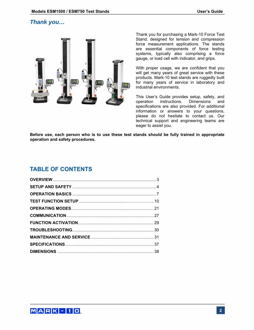
2.1 Moving the stand into position Place the stand on a sturdy, clean, and level work area free from vibration. A recessed lifting hook is provided at the top of the column for moving purposes, as shown in the image at left.
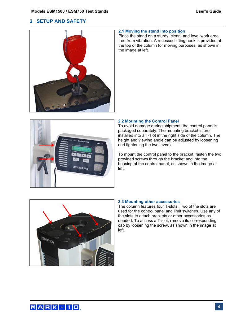
2.2 Mounting the Control Panel To avoid damage during shipment, the control panel is packaged separately. The mounting bracket is pre-installed into a T-slot in the right side of the column. The height and viewing angle can be adjusted by loosening and tightening the two levers. To mount the control panel to the bracket, fasten the two provided screws through the bracket and into the housing of the control panel, as shown in the image at left.
2.3 Mounting other accessories The column features four T-slots. Two of the slots are used for the control panel and limit switches. Use any of the slots to attach brackets or other accessories as needed. To access a T-slot, remove its corresponding cap by loosening the screw, as shown in the image at left.

Models ESM1500 / ESM750 Test Stands User’s Guide
5
2.4 Connections and Outputs The following connections and outputs are supplied in the lower rear section of the test stand’s column, as shown in the illustration below:
1. Power plug receptacle Plug the power cord in here. Refer to the Connecting Power sub-section for important safety
information.
2. Power switch
3. Control panel cable connector Plug the cable into this connector.
4. Auxiliary limit switch connector For interfacing an external limit switch, such as an interlock for a machine guard door. A pin diagram is shown below:
Note that when pins 3 and 4 are not connected, the auxiliary limits are inactive. When the +5V from pin 2 is connected to either pin 3 or pin 4, the respective limit becomes active and the crosshead is prevented from movement in that direction. The hard-wired cable and connector, as shown below, should remain in place if external limit switches are not used:
2
1
3
4
5

Models ESM1500 / ESM750 Test Stands User’s Guide
6
5. USB connector
Outputs force only or force and travel data via USB. Also allows for PC control. Plug one end of the USB cable into this connector, and the other end into a PC’s USB port. To use this output, install the USB driver provided on the Resource CD, labeled “Mark-10 USB Device”. Installation instructions may also be found on the CD or may be downloaded from www.mark-10.com.
Caution! Install the USB driver before physically connecting the tester to a PC with the USB cable.
Further instructions for configuring communication functions may be found in the Test Function Setup section.
If PC control is used, a full listing of available ASCII commands may be found in the Operating Modes section.
2.5 Installing a load cell with indicator or force gauge Once the test stand is in a stable and secure position, install a load cell and indicator, or a force gauge, with the hardware supplied. Grips and fixtures may be mounted to the load cell or force gauge and test stand base, utilizing eye ends if desired. 2.5.1 Installing a sensor and indicator (-LC test stands) Hardware to mount a Series R01 or Series R03 force sensor to the crosshead is included with the sensor. Refer to the following illustration for installation instructions:
2.5.2 Installing a force gauge (-FG test stands) A force gauge mounts directly to the mounting plate on the crosshead by aligning the dowel pin with the blind hole in the rear of the gauge’s housing. Then, install the four thumb screws in the same fashion as an indicator, as shown in the illustration above. 2.5.3 Installing the interface cable If using a Series 5 or Series 7 instrument, connect the interface cable between the instrument’s connector and the crosshead’s connector, as shown in the image below.

Models ESM1500 / ESM750 Test Stands User’s Guide
7
2.6 Safety / Proper Usage Typical materials able to be tested include manufactured items such as springs, metals, plastics, electronic components, mechanical assemblies, packaging materials, and many others. Items that should not be tested include potentially flammable substances or products, items that can shatter in an unsafe manner, and any other components that can present an exceedingly hazardous situation when acted upon by a force. Ensure that the grip or fixture is positioned to ensure axial load with respect to the load axis of the load cell or force gauge. When using a grip, ensure that it secures the sample in such a way that it is prevented from slipping out during a test, preventing a potential safety risk to the operator and others in the vicinity. If using a grip or fixture from a supplier other than Mark-10, ensure that it is constructed of suitably rugged materials and components. 2.7 Connecting Power Plug one end of the power cord into its receptacle at the rear of the stand and the other end into a wall outlet with local earth ground (3-prong connector). Before turning on power, the following safety checks and procedures should be performed:
1. Never operate the test stand if there is any visible damage to the power cord or the test stand itself. The test stand is powered by 110V/220V. Any contact with this high voltage can cause serious injury or even death.
2. Ensure that the test stand is kept away from water or any electrically conductive liquids at all times.
3. Make sure the electrical outlet powering the test stand has local earth ground (3-prong connector).
4. The test stand should be serviced by a trained technician only. Power must be disconnected before the column covers are removed.
After the above safety checks and procedures have been performed, the test stand may be powered on and is ready for operation. 3 OPERATION BASICS 3.1 Operational Safety The following safety checks and procedures should be performed before and during operation: 1. Always consider the characteristics of the sample being tested before initiating a test. A risk
assessment should be carried out beforehand to ensure that all safety measures have been addressed and implemented.

Models ESM1500 / ESM750 Test Stands User’s Guide
8
2. Wear eye and face protection when testing, especially when testing brittle samples that have the
potential to shatter under force. Be aware of the dangers posed by potential energy that can accumulate in the sample during testing. Extra bodily protection should be worn if a destructive failure of a test sample is possible.
3. Keep away from moving parts of the test stand. Loose articles of clothing should not be worn. Long
hair should be covered to avoid a hazardous situation. A Crush Hazard warning label is located on the base of the test stand. It appears as follows:
Definition: Keep any body parts and clothing clear of the area between the base of the test stand and the moving crosshead.
4. In applications where samples can shatter, or other applications that could lead to a hazardous
situation, use of a machine guard is strongly recommended.
5. When the test stand is not in use, ensure that power is turned off to prevent accidental engagement of any of the controls.
3.2 Controls
Label Function
1 SOFT KEYS Functions are determined by the corresponding text on the display.
2 UP Commences movement in the up direction.
3 STOP Stops crosshead movement.
4 DOWN Commences movement in the down direction.
5 FollowMe® Enables force-activated crosshead positioning. If this option is not installed, the message “Not Installed” flashes.
6 ZERO TRAVEL Zeroes the travel display. If this option is not installed, the message “NOT INSTALLED” flashes.
2
3
4
1
5
6

Models ESM1500 / ESM750 Test Stands User’s Guide
9
3.2 Emergency Stop The Emergency Stop button is located on the base, adjacent to the lower right corner of the column, as shown in the image at left. Press this button at any time to stop test stand motion. Rotate clockwise to release.
3.3 Modes Overview The test stands have three functional modes:
1. OPERATING MODE This is the operating mode in which testing sequences can be started and stopped.
2. TEST FUNCTION SETUP
In this mode, test functions are configured, such as rate of speed, number of cycles, password editing, and other functions.
3. FUNCTION ACTIVATION Many test stand functions, such as cycling, auto return, distance measurement, and others are ordered individually as options. The Function Activation menu provides a means of identifying which functions were purchased. Through this menu, it is also possible to enable any functions not originally purchased via an activation code. All functions are temporarily enabled for the first 160 hours of operation, as described below:
DEMO MODE The stands are shipped in Demo Mode, during which time all available functions are temporarily activated for 160 hours of operation. At power-up, a counter displays the number of hours remaining, as follows:
Press STOP to continue. At the end of this period, any functions not originally purchased will be deactivated, and will no longer be accessible from the Test Function Setup menu. Demo Mode can be suspended at any time by pressing and holding STOP while turning on power to the test stand. This mode can be re-enabled in the same manner, and will be active for the remaining time period. Refer to the Function Activation section for instructions for field activation.
R E MA I N I N G DEMO
T I ME : 1 6 0 HOURS

Models ESM1500 / ESM750 Test Stands User’s Guide
10
4 TEST FUNCTION SETUP This section provides configuration instructions for each test function.
Function Standard / OptionalSpeed - same setting applies to both directions StandardTravel indication OptionalIndependent up and down speeds OptionalHigh speed range extension Optional Low speed range extension OptionalAuto return OptionalCycling with dwell time OptionalProgrammable travel limits OptionalOverload protection OptionalPreload OptionalLoadholding OptionalBreak detection OptionalPC control OptionalFollowMe® Optional Profiles OptionalCommunication settings StandardUnits of speed measurement StandardProgrammable button configuration StandardPassword protection Standard Test stands are shipped in Demo Mode, as explained in the Overview section. After Demo Mode expires, only installed functions will be displayed in Test Function Setup. To access Test Function Setup menu, press menu from the Operating Mode home screen, which appears as follows:
After pressing menu, the initial Test Function Setup screen appears as follows:
Label Description
ESC Exits Test Function Setup, reverts to Operating Mode
< – Scrolls to the previous function – > Scrolls to the next function ENTR Selects the function, allowing it to be modified When the functions have been configured and are ready to be saved, press ESC to exit Test Function Setup. Note: Changes can be made to an unlimited number of settings before saving.
S P E E D : 0 . 0 0
me n u m i n ma x S E T
S P E E D : 2 0 . 0 0
E S C < − − > E N T R

Models ESM1500 / ESM750 Test Stands User’s Guide
11
If the PROFILES function is installed, the changes may be saved to the desired profile name. The screen appears as follows:
Label Description
ESC Exits Test Function Setup, reverts to Operating Mode
+ Scrolls to the next saved profile
EDIT Press to edit the profile name. The first character will be flashing. Press + to change the character and –> to advance to the next character.
SAVE Saves the settings under the specified profile name Refer to the Profiles sub-section for further details on selecting and deleting profiles. If the PROFILES function is not installed, the screen appears as follows:
Make the appropriate selection. 4.1 Speed, Up Speed, Down Speed (SPEED, UP SPEED, DOWN SP) If the independent up and down speed option has not been installed, the up and down speeds will be the same, and is programmed in the SPEED function. If the independent up and down speeds option is installed, UP SPEED and DN SPEED functions will be present, and may be set individually.
Default setting: 10 in/min / 250 mm/min Available settings: ESM1500 / ESM1500S: 0.001 – 90 in/min / 0.02 – 2,300 mm/min
ESM750 / ESM750S: 0.001 - 60 in/min / 0.02 - 1,525 mm/min
4.2 Auto Return (AUTO RETURN) With this function, the crosshead moves to a limit switch or soft limit (force set point, distance limit, preload, or break detection), whichever occurs first, and stops. Then, the crosshead returns to the other limit and stops. The test speed is dictated by the SPEED setting or the UP SPEED and DOWN SP settings. The return speed is always maximum speed. The maximum speed depends on whether or not the optional high speed range has been installed.
S A V E A S : E X A MP L E 1
E S C + E D I T S A V E
S A V E C H A N G E S ?
N O Y E S
U P S P E E D : 1 0 . 7 3
E S C − + E N T R
Label Description+
Increments the speed setting. Holding down + will increment at an increasingly faster rate.
–
Decrements the speed setting. Holding down – will decrement at an increasingly faster rate.
ENTR Returns to the Test Function Setup menu
ESC Exits the function without saving changes

Models ESM1500 / ESM750 Test Stands User’s Guide
12
Default setting: off Available settings: off, on
Label Description + or – Cycles through the available settings ENTR Returns to the Test Function Setup menu
ESC Exits the function without saving changes
Note: If AUTO RETURN is turned on, CYCLING is automatically turned off and the KEYS function is automatically set to MAINTAINED mode. See following pages for details on the CYCLING and KEYS functions. 4.3.1 Cycling (CYCLES) This setting allows the user to configure the number of up and down cycles through which the crosshead will sequence. One cycle consists of the crosshead moving to a limit switch or soft limit, whichever occurs first, at the specified speed, stopping for the specified amount of dwell time, and returning to the other limit at the specified speed. If the independent up and down speed function is not enabled, the speed will be the same in both directions. Default setting: 00000 (off) Available settings: 00000 – 99999
4.3.2 Upper and Lower Dwell Times (U DWELL and LO DWELL) This setting corresponds to the amount of time, in seconds, for which the crosshead stops at the limit during a cycle sequence. Note: The dwell time setting is unavailable for an auto return sequence. Default setting: 0 (no dwell time) Available settings: 0 – 9999.9
A U T O R E T U R N o f f
E S C − + E N T R
C Y C L E S : 0 0 0 0 0
E S C − + E N T R
Label Description
+
Increases the number of cycles in increments of 1. Holding down + will increment at an increasingly faster rate. If 99999 is reached the next number will be 00000 and continue incrementing.
–
Decreases the number of cycles in increments of 1. Holding down – will decrement at an increasingly faster rate. If 00000 is reached the next number will be 99999 and continue decrementing.
Press and hold + and – simultaneously
If pressed and held for 2 seconds or longer the number of cycles will change to 0.
ENTR Returns to the Test Function Setup menuESC Exits the function without saving changes

Models ESM1500 / ESM750 Test Stands User’s Guide
13
Label Description
+
Increases dwell time in increments of .1. Holding down + will increment at an increasingly faster rate. If 9999.9 is reached the next number will be 0 and continue incrementing.
–
Decreases dwell time in increments of .1. Holding down – will decrement at an increasingly faster rate. If 0 is reached the next number will be 9999.9 and continue decrementing.
ENTR Returns to the Test Function Setup menuESC Exits the function without saving changes 4.4 Upper and Lower Travel Limits (UPPER LM and LOWER LM) This setting corresponds to the travel distance the crosshead moves before stopping or cycling. Upper and lower limits are programmed individually. The programmed distances are relative to the zero position of the crosshead. The travel indicator can be zeroed by pressing the ZERO TRAVEL key. Default / available setting range: ESM1500 / ESM750: -39.000 to +39.000 in ESM1500S / ESM750S: -15.000 to +15.000
Label Description
+ Increments the travel limit setting by .001 in or .02 mm. Holding down + will increment at an increasingly fast rate.
– Decrements the travel limit setting by .001 in or .02 mm. Holding down – will increment at an increasingly fast rate.
ENTR Returns to the Test Function Setup menuESC Exits the function without saving changes
4.5.1 Overload Protection (OVERLD) The test stand protects a load cell or force gauge from overload by measuring incoming analog voltage and stopping crosshead travel when the programmed percentage of full scale has been reached. The default setting is for Mark-10 instruments (±1V full scale), however, the setting may be changed to ±2V or ±4V to accommodate other instruments. Default setting: OFF Available settings: MARK-10, OTHER 2V, OTHER 4V, OFF
4.5.2 Compression and Tension Overload Settings (COMP OVERLD and TEN OVERLD) This setting corresponds to the percentage of full scale (in lbF units) at which crosshead travel stops. For example, a setting of 80% for a 1,000 lbF capacity load cell would stop crosshead travel when approximately 800 lbF is reached.
H I D WE L L : 0 0 0 0 . 0
E S C − + E N T R
H I L I M I T : 2 . 0 5 8
E S C − + E N T R
O V E R L D : MA R K - 1 0
E S C − + E N T R

Models ESM1500 / ESM750 Test Stands User’s Guide
14
Note: When the crosshead is moving in the UP direction, only the tension overload setting applies. When the crosshead is moving in the DOWN direction, only the compression overload setting applies. Default setting: 100% Available settings: 20% - 120% (10% increments)
Label Description
+ or – Increases or decreases the value.ENTR Returns to the Test Function Setup menuESC Exits the function without saving changes 4.6.1 Preload (PRELOAD) This setting corresponds to the test stand’s response to an initial load, referred to as a preload. The crosshead can stop and/or zero the travel display when the preload has been reached. This function is useful for applications such as spring testing, elongation testing, and tensile and compression testing of various materials. In effect, it establishes a reference point. It is also sometimes referred to as a touch. Note: Before the start of a preload sequence, the crosshead must be positioned at either the upper or lower physical limit switch. Default setting: OFF Available settings: STOP, STOP/ZERO, ZERO/GO, OFF
Label Description
+ or – Cycles through the available settings listed below:STOP Crosshead stops when preload has been reachedSTOP, ZERO Crosshead stops when preload has been reached, then zeroes the travel displayZERO, GO Travel display is zeroed when preload has been reached, crosshead does not stopENTR Returns to the Test Function Setup menuESC Exits the function without saving changes 4.6.2 Preload Value (PRELD %FS) This setting corresponds to a preload value, defined as a percentage of the load cell or force gauges’ full scale, in lbF units. The test stand’s response, as described in the previous section, occurs when this value has been reached. Note: In low force applications, consider test stand vibration and crosshead acceleration, as they can be significant enough to produce a force exceeding the preload value. Default setting: 1% Available settings: 0 – 100%
C O MP O V E R L D : 1 0 0 %
E S C − + E N T R
P R E L O A D : Z E R O , G O
E S C − + E N T R

Models ESM1500 / ESM750 Test Stands User’s Guide
15
Label Description
+ or – Increases or decreases the value, in increments of .1
ENTR Returns to the Test Function Setup menu
ESC Exits the function without saving changes
4.7 Loadholding This setting directs the test stand to dynamically adjust the crosshead position to maintain a programmed force. The force is programmed as a set point in a Series 5 or 7 instrument (refer to the respective user’s guide for details). If the CYCLING option has been installed, loadholding will be active for the period of time as defined in the Upper Dwell and Lower Dwell settings. If CYCLING has not been installed, loadholding will continue indefinitely. Pressing STOP will end loadholding. Default setting: OFF Available settings: ON, OFF
Label Description
+ or – Cycles through the available settings ENTR Returns to the Test Function Setup menuESC Exits the function without saving changes 4.8.1 Break Detection This setting directs the test stand to stop when a sample break has occurred. The test stand stops when the force has decreased to a specified percentage of peak. Default setting: OFF Available settings: ON, OFF
Label Description
+ or – Cycles through the available settings ENTR Returns to the Test Function Setup menuESC Exits the function without saving changes 4.8.2 Break Detection Activation Threshold This setting corresponds to the force threshold after which the break detection function is active. The threshold is provided to prevent false activation of the function during sample handling. The threshold is defined as a percentage of full scale of the load cell or force gauge. For example, for a 500 lbF capacity load cell, a setting of 10% represents 50 lbF. Default setting: 10% Available settings: 1% - 95% (1% increments)
P R E L D %F S : 0 1 . 0
E S C − + E N T R
L O A D H O L D I N G : O N
E S C − + E N T R
B R E A K D E T E C T : O N
E S C − + E N T R

Models ESM1500 / ESM750 Test Stands User’s Guide
16
Label Description
+ or – Increases or decreases the value. ENTR Returns to the Test Function Setup menuESC Exits the function without saving changes 4.8.3 Break Detection Percentage of Peak This setting corresponds to the force trigger for break detection, defined as a percentage of peak force. For example: A sample is pulled to 500 lbF, then breaks. The break detection percentage setting is 60%. After the sample breaks, the force rapidly decreases to 300 lbF (60% of peak), and causes the test stand to stop. Default setting: 80% Available settings: 1% - 95% (1% increments)
Label Description
+ or – Increases or decreases the value. ENTR Returns to the Test Function Setup menuESC Exits the function without saving changes Note: When using the test stand with a Series 7 instrument, enable Break Detection in either the test stand or the instrument – not both. The function will not work if simultaneously enabled in both devices. 4.9 Control Source (CONTROL) This setting corresponds to the source of test stand control, as follows:
CONSOLE The test stand is controlled either from the control panel or from MESURgauge Plus software running on a PC.
PC The test stand is controlled from a custom written PC application (not MESURgauge Plus). If any functions are changed on the front panel, these settings will be ignored, except for Auto Return or Cycling. If either of these functions is turned on, PC control will be turned off.
Default setting: CONSOLE Available settings: CONSOLE, PC
B R K T H R E S H : 8 0 %
E S C − + E N T R
B R E A K % P E A K : 1 0
E S C − + E N T R
C O N T R O L : C O N S O L E
E S C − + E N T R
Models ESM1500 / ESM750 Test Stands User’s Guide
17
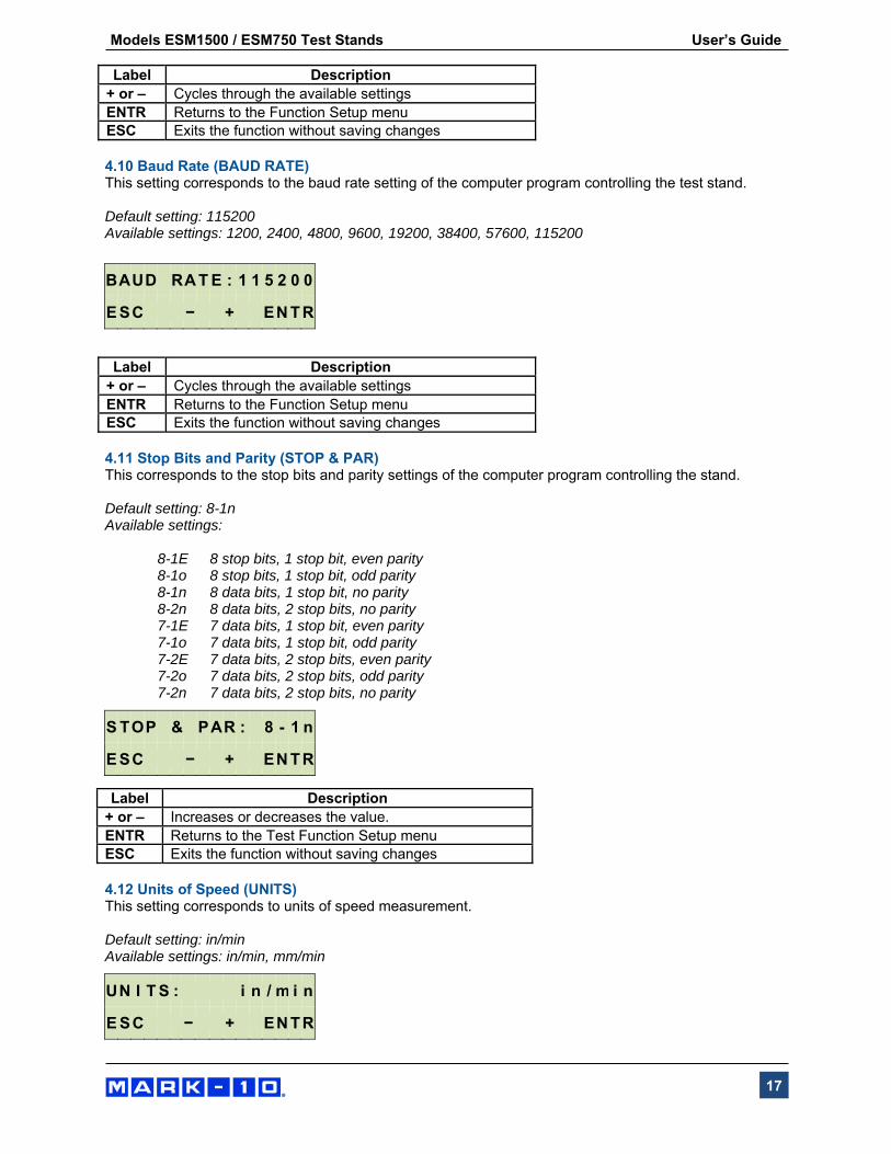
Label Description + or – Cycles through the available settings ENTR Returns to the Function Setup menu ESC Exits the function without saving changes 4.10 Baud Rate (BAUD RATE) This setting corresponds to the baud rate setting of the computer program controlling the test stand. Default setting: 115200 Available settings: 1200, 2400, 4800, 9600, 19200, 38400, 57600, 115200
Label Description
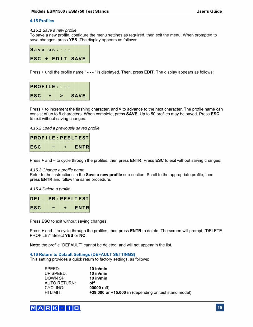
+ or – Cycles through the available settings ENTR Returns to the Function Setup menu ESC Exits the function without saving changes 4.11 Stop Bits and Parity (STOP & PAR) This corresponds to the stop bits and parity settings of the computer program controlling the stand. Default setting: 8-1n Available settings:
8-1E 8 stop bits, 1 stop bit, even parity 8-1o 8 stop bits, 1 stop bit, odd parity 8-1n 8 data bits, 1 stop bit, no parity 8-2n 8 data bits, 2 stop bits, no parity 7-1E 7 data bits, 1 stop bit, even parity 7-1o 7 data bits, 1 stop bit, odd parity 7-2E 7 data bits, 2 stop bits, even parity 7-2o 7 data bits, 2 stop bits, odd parity 7-2n 7 data bits, 2 stop bits, no parity
Label Description + or – Increases or decreases the value. ENTR Returns to the Test Function Setup menuESC Exits the function without saving changes 4.12 Units of Speed (UNITS) This setting corresponds to units of speed measurement. Default setting: in/min Available settings: in/min, mm/min
B A U D R A T E : 1 1 5 2 0 0
E S C − + E N T R
S T O P & P A R : 8 - 1 n
E S C − + E N T R
U N I T S : i n / m i n
E S C − + E N T R

Models ESM1500 / ESM750 Test Stands User’s Guide
18
Label Description
+ or – Cycles through the available settings ENTR Returns to the Test Function Setup menuESC Exits the function without saving changes 4.13 Programmable Button Function (KEYS) Three button function modes are available:
1. Maintained
The crosshead will move continuously once the button has been pressed and held. Subsequently pressing STOP will stop crosshead motion.
2. Momentary
The crosshead will move only if the button is held down. Releasing the button will stop movement immediately.
3. Auto Holding down the button for more than 0.5 second will enter momentary mode, at which time an audible indicator will sound and the LED indicator on the button pushed will be illuminated. A short tap on the button will operate the test stand in maintained mode. Pressing STOP during maintained mode will stop crosshead motion.
Default setting: maintained Available settings: maintained, momentary, auto
Label Description
+ or – Cycles through the available settings ENTR Returns to the Test Function Setup menuESC Exits the function without saving changes 4.14 FollowMe® (FollowMe) Crosshead responds to manually pushing or pulling on the force gauge shaft or load cell. Increasing force produces greater speeds. Ideal for quick positioning during sample loading and unloading.
CAUTION! Exercise extreme caution when handling low force load cells and gauges, as overload can occur.
Default setting: OFF Available settings: ON, OFF
Label Description
+ or – Cycles through the available settings ENTR Returns to the Test Function Setup menuESC Exits the function without saving changes
K E Y S : M A I N T A I N E D
E S C − + E N T R
F O L L O WM E : O F F
E S C − + E N T R
Models ESM1500 / ESM750 Test Stands User’s Guide
19
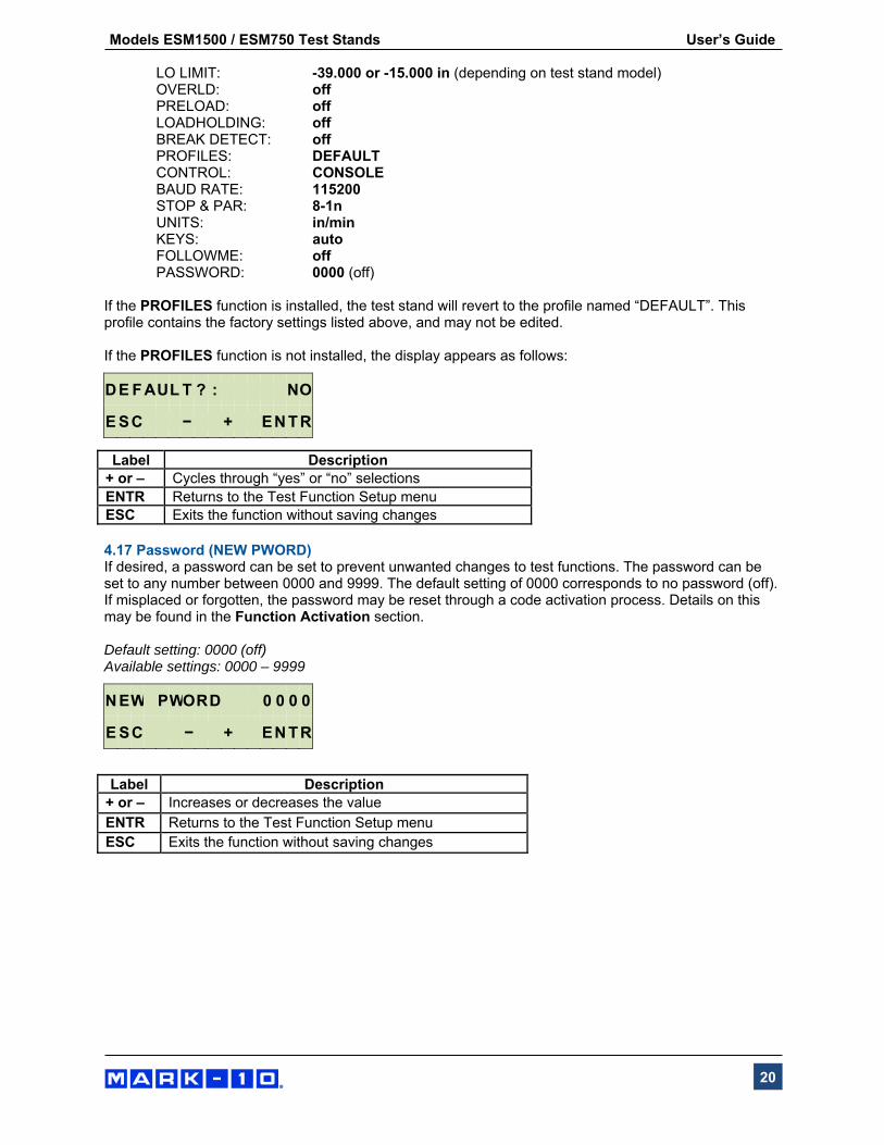
4.15 Profiles 4.15.1 Save a new profile To save a new profile, configure the menu settings as required, then exit the menu. When prompted to save changes, press YES. The display appears as follows:
Press + until the profile name “ - - - “ is displayed. Then, press EDIT. The display appears as follows:
Press + to increment the flashing character, and > to advance to the next character. The profile name can consist of up to 8 characters. When complete, press SAVE. Up to 50 profiles may be saved. Press ESC to exit without saving changes. 4.15.2 Load a previously saved profile
Press + and – to cycle through the profiles, then press ENTR. Press ESC to exit without saving changes. 4.15.3 Change a profile name Refer to the instructions in the Save a new profile sub-section. Scroll to the appropriate profile, then press ENTR and follow the same procedure. 4.15.4 Delete a profile
Press ESC to exit without saving changes. Press + and – to cycle through the profiles, then press ENTR to delete. The screen will prompt, “DELETE PROFILE?” Select YES or NO. Note: the profile “DEFAULT” cannot be deleted, and will not appear in the list. 4.16 Return to Default Settings (DEFAULT SETTINGS) This setting provides a quick return to factory settings, as follows:
SPEED: 10 in/min UP SPEED: 10 in/min DOWN SP: 10 in/min AUTO RETURN: off CYCLING: 00000 (off)
HI LIMIT: +39.000 or +15.000 in (depending on test stand model)
S a v e a s : - - -
E S C + E D I T S A V E
P R O F I L E : - - -
E S C + > S A V E
P R O F I L E : P E E L T E S T
E S C − + E N T R
D E L . P R : P E E L T E S T
E S C − + E N T R
Models ESM1500 / ESM750 Test Stands User’s Guide
20
LO LIMIT: -39.000 or -15.000 in (depending on test stand model) OVERLD: off PRELOAD: off LOADHOLDING: off BREAK DETECT: off PROFILES: DEFAULT
CONTROL: CONSOLE BAUD RATE: 115200
STOP & PAR: 8-1n UNITS: in/min
KEYS: auto FOLLOWME: off PASSWORD: 0000 (off)
If the PROFILES function is installed, the test stand will revert to the profile named “DEFAULT”. This profile contains the factory settings listed above, and may not be edited. If the PROFILES function is not installed, the display appears as follows:
Label Description+ or – Cycles through “yes” or “no” selections ENTR Returns to the Test Function Setup menuESC Exits the function without saving changes 4.17 Password (NEW PWORD) If desired, a password can be set to prevent unwanted changes to test functions. The password can be set to any number between 0000 and 9999. The default setting of 0000 corresponds to no password (off). If misplaced or forgotten, the password may be reset through a code activation process. Details on this may be found in the Function Activation section. Default setting: 0000 (off) Available settings: 0000 – 9999
Label Description
+ or – Increases or decreases the value ENTR Returns to the Test Function Setup menu ESC Exits the function without saving changes
D E F A U L T ? : N O
E S C − + E N T R
N E W P WO R D 0 0 0 0
E S C − + E N T R
Models ESM1500 / ESM750 Test Stands User’s Guide
21
5 OPERATING MODES 5.1 Overview The test stand can be operated in several modes, including combinations of these modes:
1. FollowMe® Mode Crosshead movement responds to pushing or pulling on the force gauge shaft or load cell. Increasing force produces greater speeds. Useful for quick positioning during setup and sample loading/unloading.
2. Basic Mode Manual control of crosshead motion. 3. Auto Return Mode Crosshead moves to a limit switch or force set point, travel distance, preload, or sample
break (referred to as soft limits), whichever occurs first. Then, it reverses and moves at maximum speed to the other limit, whichever occurs first.
4. Cycling Mode Crosshead cycles between limits at the selected speed(s), and pauses at each limit or set
point for a selected period of time. 5. Preload Mode Crosshead moves until the preload has been reached, and performs the action programmed
in the setting. An auto-return, cycle/dwell time, or break detection sequence may follow. 6. Loadholding Mode Crosshead moves to a force set point, stops, then dynamically adjusts position to maintain
the programmed force. An auto-return or cycle/dwell time sequence may follow. 7. Break Detection Crosshead stops when a sample break has been detected. An auto-return or cycle/dwell time
sequence may follow. 8. PC Control Mode
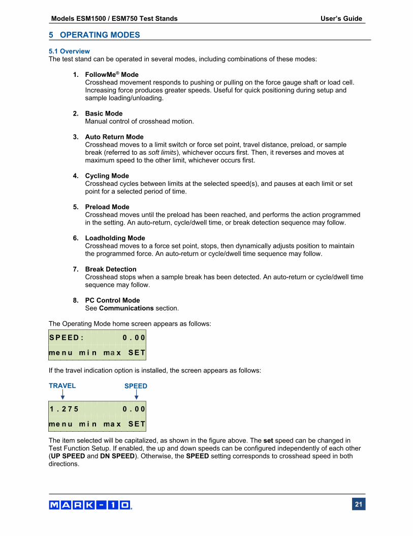
See Communications section. The Operating Mode home screen appears as follows:
If the travel indication option is installed, the screen appears as follows:
The item selected will be capitalized, as shown in the figure above. The set speed can be changed in Test Function Setup. If enabled, the up and down speeds can be configured independently of each other (UP SPEED and DN SPEED). Otherwise, the SPEED setting corresponds to crosshead speed in both directions.
S P E E D : 0 . 0 0
me n u m i n ma x S E T
1 . 2 7 5 0 . 0 0
me n u m i n ma x S E T
TRAVEL SPEED
Models ESM1500 / ESM750 Test Stands User’s Guide
22
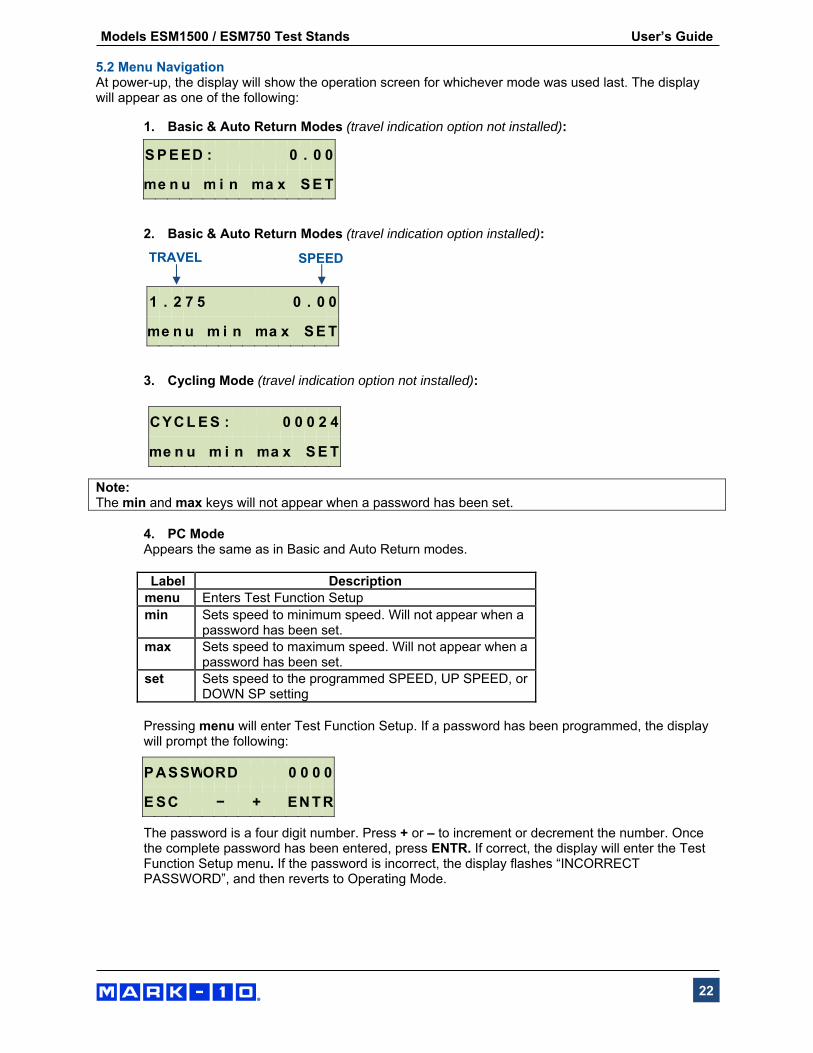
5.2 Menu Navigation At power-up, the display will show the operation screen for whichever mode was used last. The display will appear as one of the following:
1. Basic & Auto Return Modes (travel indication option not installed):
2. Basic & Auto Return Modes (travel indication option installed):
3. Cycling Mode (travel indication option not installed):
Note: The min and max keys will not appear when a password has been set.
4. PC Mode Appears the same as in Basic and Auto Return modes. Label Descriptionmenu Enters Test Function Setup min Sets speed to minimum speed. Will not appear when a
password has been set.max Sets speed to maximum speed. Will not appear when a
password has been set.set Sets speed to the programmed SPEED, UP SPEED, or
DOWN SP setting
Pressing menu will enter Test Function Setup. If a password has been programmed, the display will prompt the following:
The password is a four digit number. Press + or – to increment or decrement the number. Once the complete password has been entered, press ENTR. If correct, the display will enter the Test Function Setup menu. If the password is incorrect, the display flashes “INCORRECT PASSWORD”, and then reverts to Operating Mode.
S P E E D : 0 . 0 0
me n u m i n ma x S E T
1 . 2 7 5 0 . 0 0
me n u m i n ma x S E T
C Y C L E S : 0 0 0 2 4
me n u m i n ma x S E T
P A S S WO R D 0 0 0 0
E S C − + E N T R
TRAVEL SPEED

Models ESM1500 / ESM750 Test Stands User’s Guide
23
5.3 FollowMe® Mode Crosshead movement responds to manually pushing or pulling on the force gauge shaft or load cell. Increasing force produces greater speeds. Ideal for quick positioning during sample loading and unloading. To arm FollowMe® mode, press the FollowMe® key. The display appears as follows:
CAUTION! Exercise extreme caution when handling low force load cells and gauges, as overload can occur.
If no force is detected for five seconds after pressing the FollowMe® key, the function becomes inactive, and the display flashes “FOLLOWME OFF”. If the FollowMe® function has not been enabled in Test Function Setup, pressing the key will not arm the function. The display will flash “NOT ENABLED”. If the FollowMe® function has not been installed in the test stand, pressing the key will not arm the function. The display will flash “NOT INSTALLED”. 5.4 Basic Mode The crosshead moves upward when UP is pressed, and downward when DOWN is pressed. When the crosshead is in motion, an LED indicator on the button pushed will be illuminated. The KEYS setting controls how crosshead movement responds to the push of the UP and DOWN buttons. The three settings are: 1. Maintained (default)
The crosshead will move continuously once the button has been pressed. Subsequently pressing STOP will stop crosshead motion.
2. Momentary
The crosshead will move only if the button is pressed and held. Releasing the button will stop movement immediately.
3. Auto
Holding down the button for more than 0.5 seconds will enter Momentary mode, at which time an audible indicator will sound and the LED indicator on the button pushed will be illuminated. A short tap on the button will operate the test stand in Maintained mode. Pressing STOP during Maintained mode will stop crosshead motion. To resume the test, press UP or DOWN again.
Pressing EMERGENCY STOP will immediately stop crosshead motion in any mode. To release, twist the button clockwise until it assumes its original position. To resume the test, press UP or DOWN. Crosshead movement will take place until a limit has been reached. If the crosshead has stopped at a soft limit, the limit condition may be overridden by pressing and holding UP or DOWN for two seconds.
S P E E D : 0 . 0 0
F o l l o w Me A c t i v e
Models ESM1500 / ESM750 Test Stands User’s Guide
24
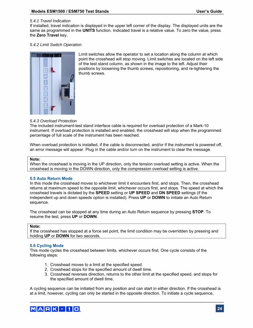
5.4.1 Travel Indication If installed, travel indication is displayed in the upper left corner of the display. The displayed units are the same as programmed in the UNITS function. Indicated travel is a relative value. To zero the value, press the Zero Travel key. 5.4.2 Limit Switch Operation
Limit switches allow the operator to set a location along the column at which point the crosshead will stop moving. Limit switches are located on the left side of the test stand column, as shown in the image to the left. Adjust their positions by loosening the thumb screws, repositioning, and re-tightening the thumb screws.
5.4.3 Overload Protection The included instrument-test stand interface cable is required for overload protection of a Mark-10 instrument. If overload protection is installed and enabled, the crosshead will stop when the programmed percentage of full scale of the instrument has been reached. When overload protection is installed, if the cable is disconnected, and/or if the instrument is powered off, an error message will appear. Plug in the cable and/or turn on the instrument to clear the message. Note: When the crosshead is moving in the UP direction, only the tension overload setting is active. When the crosshead is moving in the DOWN direction, only the compression overload setting is active. 5.5 Auto Return Mode In this mode the crosshead moves to whichever limit it encounters first, and stops. Then, the crosshead returns at maximum speed to the opposite limit, whichever occurs first, and stops. The speed at which the crosshead travels is dictated by the SPEED setting or UP SPEED and DN SPEED settings (if the independent up and down speeds option is installed). Press UP or DOWN to initiate an Auto Return sequence. The crosshead can be stopped at any time during an Auto Return sequence by pressing STOP. To resume the test, press UP or DOWN. Note: If the crosshead has stopped at a force set point, the limit condition may be overridden by pressing and holding UP or DOWN for two seconds. 5.6 Cycling Mode This mode cycles the crosshead between limits, whichever occurs first. One cycle consists of the following steps:
1. Crosshead moves to a limit at the specified speed. 2. Crosshead stops for the specified amount of dwell time. 3. Crosshead reverses direction, returns to the other limit at the specified speed, and stops for
the specified amount of dwell time.
A cycling sequence can be initiated from any position and can start in either direction. If the crosshead is at a limit, however, cycling can only be started in the opposite direction. To initiate a cycle sequence,

Models ESM1500 / ESM750 Test Stands User’s Guide
25
press UP or DOWN. During a cycle sequence, a counter will be displayed, indicating the number of cycles remaining, as shown below:
As in Basic Mode, the min, max, and set soft keys are active during crosshead movement. When the cycling sequence and the crosshead has stopped at a soft limit, the limit condition may be overridden by pressing and holding UP or DOWN. 5.6.1 Dwell time Dwell time is the amount of time, in seconds, for which the crosshead stops at a limit during a cycle sequence. When the crosshead has reached a limit, a counter will be displayed, shown as follows:
If the DWELL U and/or DWELL L settings are set to 0, the crosshead will immediately reverse direction upon reaching the corresponding limit, and no counter will be displayed. The cycle sequence may be interrupted before it has been completed by pressing STOP. A soft key labeled RESET will appear as follows:
At this point, there are two options:
1. Cancel the cycle sequence: Press RESET to stop and reset the cycle sequence. The cycle counter will revert to the
number of cycles originally programmed.
2. Resume the cycle sequence: Press UP or DOWN to resume.
Once the sequence has been completed, the screen will revert to the number of cycles programmed originally. To begin another cycle test, press UP or DOWN. Travel indication and limit switch operation is the same as in Basic Mode. 5.7 Preload Mode In this mode, the crosshead moves at the set speed (10 in/min [250 mm/min] maximum) until the programmed preload value has been reached. If moving in the up direction, a tension preload is required. If moving in the down direction, a compression preload is required. When the preload is reached, the sequence of events programmed in the Preload function occurs. If the ZERO,GO setting is selected, and if the set speed is greater than 10 in/min, the crosshead speed will revert to this setting after the travel indicator is zeroed. Note 1: Before the start of a preload sequence, the crosshead must be positioned at either the upper or lower physical limit switch. Note 2: Preload and Load Holding cannot be enabled simultaneously.
C Y C L E S 0 0 0 2 4
me n u m i n ma x S E T
D WE L L : 0 0 0 1 . 5
me n u m i n ma x S E T
C Y C L E S : 0 0 0 2 4
R E S E T
Models ESM1500 / ESM750 Test Stands User’s Guide
26
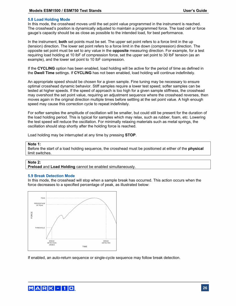
5.8 Load Holding Mode In this mode, the crosshead moves until the set point value programmed in the instrument is reached. The crosshead’s position is dynamically adjusted to maintain a programmed force. The load cell or force gauge’s capacity should be as close as possible to the intended load, for best performance. In the instrument, both set points must be set. The upper set point refers to a force limit in the up (tension) direction. The lower set point refers to a force limit in the down (compression) direction. The opposite set point must be set to any value in the opposite measuring direction. For example, for a test requiring load holding at 10 lbF of compression force, set the upper set point to 30 lbF tension (as an example), and the lower set point to 10 lbF compression. If the CYCLING option has been enabled, load holding will be active for the period of time as defined in the Dwell Time settings. If CYCLING has not been enabled, load holding will continue indefinitely. An appropriate speed should be chosen for a given sample. Fine tuning may be necessary to ensure optimal crosshead dynamic behavior. Stiff samples require a lower test speed; softer samples can be tested at higher speeds. If the speed of approach is too high for a given sample stiffness, the crosshead may overshoot the set point value, requiring an adjustment sequence where the crosshead reverses, then moves again in the original direction multiple times before settling at the set point value. A high enough speed may cause this correction cycle to repeat indefinitely. For softer samples the amplitude of oscillation will be smaller, but could still be present for the duration of the load holding period. This is typical for samples which may relax, such as rubber, foam, etc. Lowering the test speed will reduce the oscillation. For minimally relaxing materials such as metal springs, the oscillation should stop shortly after the holding force is reached. Load holding may be interrupted at any time by pressing STOP. Note 1: Before the start of a load holding sequence, the crosshead must be positioned at either of the physical limit switches. Note 2: Preload and Load Holding cannot be enabled simultaneously. 5.9 Break Detection Mode In this mode, the crosshead will stop when a sample break has occurred. This action occurs when the force decreases to a specified percentage of peak, as illustrated below:
If enabled, an auto-return sequence or single-cycle sequence may follow break detection.
Models ESM1500 / ESM750 Test Stands User’s Guide
27
6 COMMUNICATION 6.1 Setup The test stand can transmit force and travel (optional) data to a PC. The following settings are required for proper functioning of all test stand functions and data output:
Force gauge / indicator (Series 5 / 7 only): - RS-232 communication enabled - 115,200 baud rate
Test stand menu: - CONTROL: CONSOLE (this menu is only shown if the PC Control function is installed; PC
Control is not required for data output) - STOP & PAR (stop bits and parity): 8-1n (8 data bits, one stop bit, no parity)
Connection cables: - Gauge / indicator to test stand: Part no. 09-1214 - Test stand to PC (USB): Part no. 09-1158
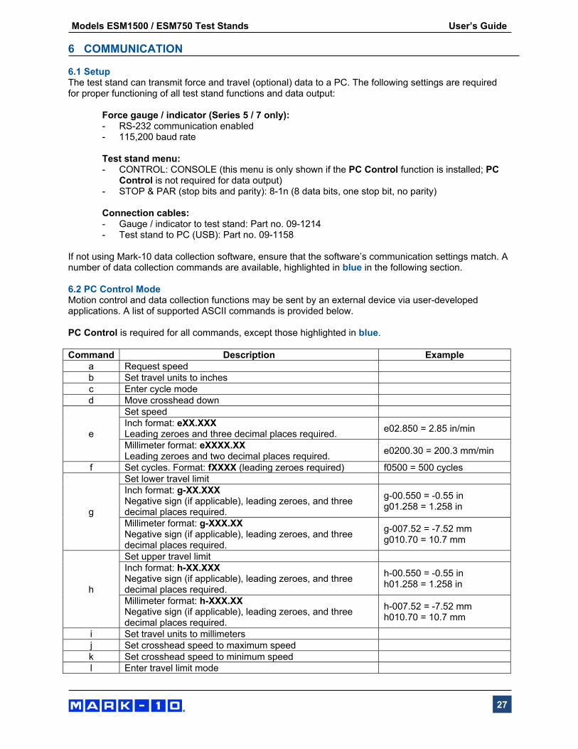
If not using Mark-10 data collection software, ensure that the software’s communication settings match. A number of data collection commands are available, highlighted in blue in the following section. 6.2 PC Control Mode Motion control and data collection functions may be sent by an external device via user-developed applications. A list of supported ASCII commands is provided below. PC Control is required for all commands, except those highlighted in blue. Command Description Example
a Request speed b Set travel units to inches c Enter cycle mode d Move crosshead down
e
Set speed Inch format: eXX.XXX Leading zeroes and three decimal places required.
e02.850 = 2.85 in/min
Millimeter format: eXXXX.XX Leading zeroes and two decimal places required.
e0200.30 = 200.3 mm/min
f Set cycles. Format: fXXXX (leading zeroes required) f0500 = 500 cycles
g
Set lower travel limit Inch format: g-XX.XXX Negative sign (if applicable), leading zeroes, and three decimal places required.
g-00.550 = -0.55 in g01.258 = 1.258 in
Millimeter format: g-XXX.XX Negative sign (if applicable), leading zeroes, and three decimal places required.
g-007.52 = -7.52 mm g010.70 = 10.7 mm
h
Set upper travel limit Inch format: h-XX.XXX Negative sign (if applicable), leading zeroes, and three decimal places required.
h-00.550 = -0.55 in h01.258 = 1.258 in
Millimeter format: h-XXX.XX Negative sign (if applicable), leading zeroes, and three decimal places required.
h-007.52 = -7.52 mm h010.70 = 10.7 mm
i Set travel units to millimetersj Set crosshead speed to maximum speedk Set crosshead speed to minimum speedl Enter travel limit mode
Models ESM1500 / ESM750 Test Stands User’s Guide
28
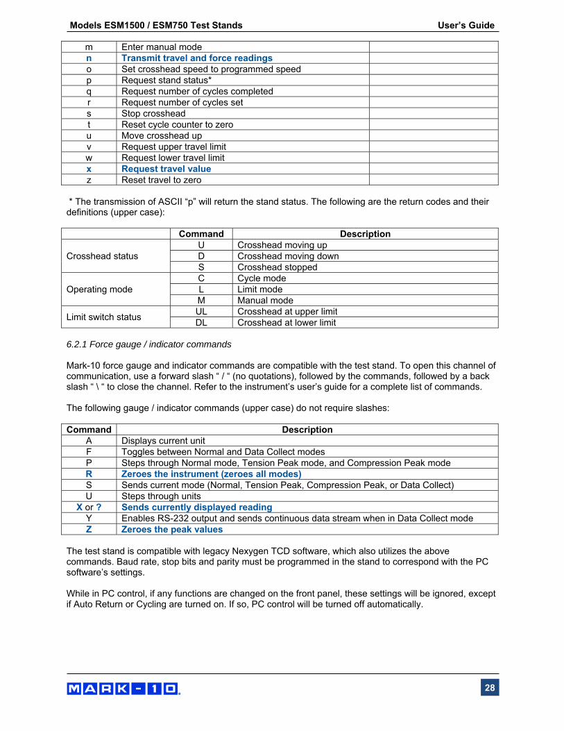
m Enter manual mode n Transmit travel and force readingso Set crosshead speed to programmed speedp Request stand status* q Request number of cycles completedr Request number of cycles sets Stop crosshead t Reset cycle counter to zerou Move crosshead up v Request upper travel limit w Request lower travel limit x Request travel value z Reset travel to zero
* The transmission of ASCII “p” will return the stand status. The following are the return codes and their definitions (upper case): Command Description
Crosshead status U Crosshead moving upD Crosshead moving downS Crosshead stopped
Operating mode C Cycle modeL Limit modeM Manual mode
Limit switch status UL Crosshead at upper limitDL Crosshead at lower limit
6.2.1 Force gauge / indicator commands Mark-10 force gauge and indicator commands are compatible with the test stand. To open this channel of communication, use a forward slash “ / “ (no quotations), followed by the commands, followed by a back slash “ \ “ to close the channel. Refer to the instrument’s user’s guide for a complete list of commands. The following gauge / indicator commands (upper case) do not require slashes: Command Description
A Displays current unit F Toggles between Normal and Data Collect modesP Steps through Normal mode, Tension Peak mode, and Compression Peak mode R Zeroes the instrument (zeroes all modes)S Sends current mode (Normal, Tension Peak, Compression Peak, or Data Collect)U Steps through units
X or ? Sends currently displayed readingY Enables RS-232 output and sends continuous data stream when in Data Collect modeZ Zeroes the peak values
The test stand is compatible with legacy Nexygen TCD software, which also utilizes the above commands. Baud rate, stop bits and parity must be programmed in the stand to correspond with the PC software’s settings. While in PC control, if any functions are changed on the front panel, these settings will be ignored, except if Auto Return or Cycling are turned on. If so, PC control will be turned off automatically.
Models ESM1500 / ESM750 Test Stands User’s Guide
29
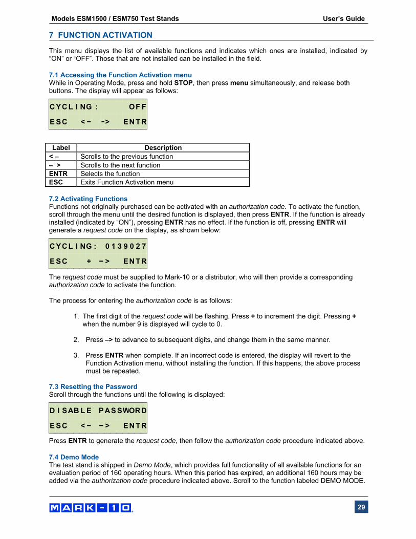
7 FUNCTION ACTIVATION This menu displays the list of available functions and indicates which ones are installed, indicated by “ON” or “OFF”. Those that are not installed can be installed in the field. 7.1 Accessing the Function Activation menu While in Operating Mode, press and hold STOP, then press menu simultaneously, and release both buttons. The display will appear as follows:
Label Description
< – Scrolls to the previous function – > Scrolls to the next function ENTR Selects the function ESC Exits Function Activation menu 7.2 Activating Functions Functions not originally purchased can be activated with an authorization code. To activate the function, scroll through the menu until the desired function is displayed, then press ENTR. If the function is already installed (indicated by “ON”), pressing ENTR has no effect. If the function is off, pressing ENTR will generate a request code on the display, as shown below:
The request code must be supplied to Mark-10 or a distributor, who will then provide a corresponding authorization code to activate the function. The process for entering the authorization code is as follows:
1. The first digit of the request code will be flashing. Press + to increment the digit. Pressing +
when the number 9 is displayed will cycle to 0. 2. Press –> to advance to subsequent digits, and change them in the same manner.
3. Press ENTR when complete. If an incorrect code is entered, the display will revert to the
Function Activation menu, without installing the function. If this happens, the above process must be repeated.
7.3 Resetting the Password Scroll through the functions until the following is displayed:
Press ENTR to generate the request code, then follow the authorization code procedure indicated above.
7.4 Demo Mode The test stand is shipped in Demo Mode, which provides full functionality of all available functions for an evaluation period of 160 operating hours. When this period has expired, an additional 160 hours may be added via the authorization code procedure indicated above. Scroll to the function labeled DEMO MODE.
C Y C L I N G : O F F
E S C < − −> E N T R
C Y C L I N G : 0 1 3 9 0 2 7
E S C + − > E N T R
D I S A B L E P A S S WO R D
E S C < − − > E N T R
Models ESM1500 / ESM750 Test Stands User’s Guide
30
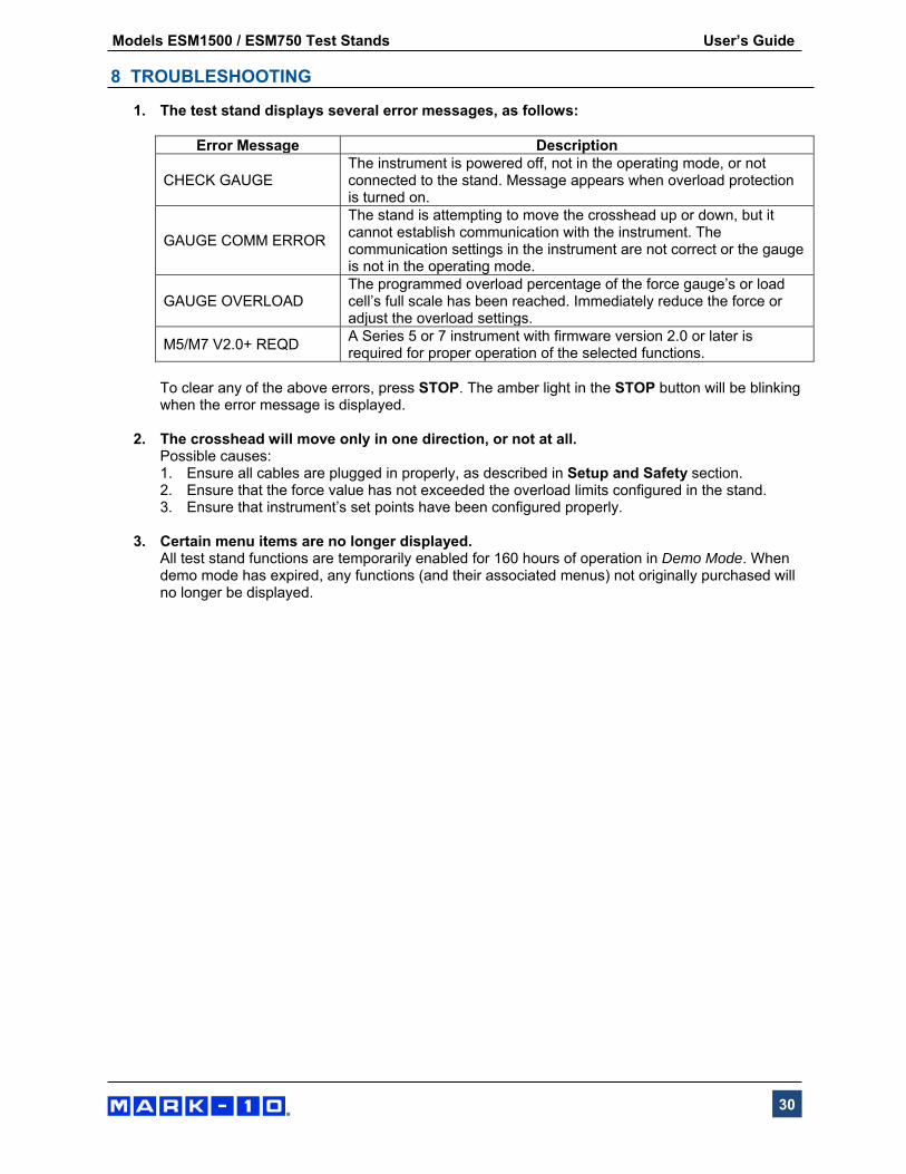
8 TROUBLESHOOTING
1. The test stand displays several error messages, as follows:
Error Message Description
CHECK GAUGE The instrument is powered off, not in the operating mode, or not connected to the stand. Message appears when overload protection is turned on.
GAUGE COMM ERROR
The stand is attempting to move the crosshead up or down, but it cannot establish communication with the instrument. The communication settings in the instrument are not correct or the gauge is not in the operating mode.
GAUGE OVERLOAD The programmed overload percentage of the force gauge’s or load cell’s full scale has been reached. Immediately reduce the force or adjust the overload settings.
M5/M7 V2.0+ REQD A Series 5 or 7 instrument with firmware version 2.0 or later is required for proper operation of the selected functions.
To clear any of the above errors, press STOP. The amber light in the STOP button will be blinking when the error message is displayed.
2. The crosshead will move only in one direction, or not at all.
Possible causes: 1. Ensure all cables are plugged in properly, as described in Setup and Safety section. 2. Ensure that the force value has not exceeded the overload limits configured in the stand. 3. Ensure that instrument’s set points have been configured properly.
3. Certain menu items are no longer displayed.
All test stand functions are temporarily enabled for 160 hours of operation in Demo Mode. When demo mode has expired, any functions (and their associated menus) not originally purchased will no longer be displayed.
Models ESM1500 / ESM750 Test Stands User’s Guide
31
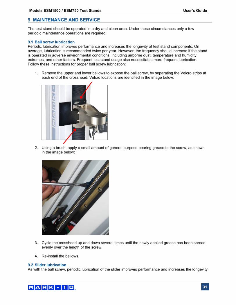
9 MAINTENANCE AND SERVICE The test stand should be operated in a dry and clean area. Under these circumstances only a few periodic maintenance operations are required: 9.1 Ball screw lubrication Periodic lubrication improves performance and increases the longevity of test stand components. On average, lubrication is recommended twice per year. However, the frequency should increase if the stand is operated in adverse environmental conditions, including airborne dust, temperature and humidity extremes, and other factors. Frequent test stand usage also necessitates more frequent lubrication. Follow these instructions for proper ball screw lubrication:
1. Remove the upper and lower bellows to expose the ball screw, by separating the Velcro strips at each end of the crosshead. Velcro locations are identified in the image below:
2. Using a brush, apply a small amount of general purpose bearing grease to the screw, as shown in the image below:
3. Cycle the crosshead up and down several times until the newly applied grease has been spread evenly over the length of the screw.
4. Re-install the bellows.
9.2 Slider lubrication As with the ball screw, periodic lubrication of the slider improves performance and increases the longevity

Models ESM1500 / ESM750 Test Stands User’s Guide
32
of test stand components. Frequency depends on environmental conditions and usage. Follow these instructions for proper slider lubrication:
1. Lay the test stand on its side on a flat and secure working surface. Exercise caution while doing so, as the test stand is heavy.
2. Remove the upper and lower bellows to expose the slider, as per the instructions above.
3. Locate the grease receptacle on the slider, identified in the below image:
4. Using a grease gun, add general purpose bearing grease to the inside of the slider until full. Wipe clean any spillage. Refer to the image below:
5. Cycle the crosshead up and down several times until the newly applied grease has been spread evenly over the length of the slide.
6. Re-install the bellows. 9.3 Bearing lubrication As with the ball screw and slider, periodic lubrication of the bearings improves performance and increases the longevity of test stand components. Frequency depends on environmental conditions and usage. Follow these instructions for proper lubrication: Lay the test stand on its side on a flat and secure working surface. Exercise caution while doing so, as the test stand is heavy.

Models ESM1500 / ESM750 Test Stands User’s Guide
33
9.3.1 Upper bearing lubrication
1. Remove the large, round plastic cover in the top of the end cap to expose the bearing, identified in the image below:
2. Apply general purpose bearing grease along the perimeter of the bearing. Wipe clean any excess grease.
3. Reinsert the plastic cover, as per above.
9.3.2 Lower bearing lubrication
1. Remove the base from the column by removing the six screws, as identified in the image below:
Exercise caution, as the base plate is heavy. The underside of the column appears as follows:
Models ESM1500 / ESM750 Test Stands User’s Guide
34
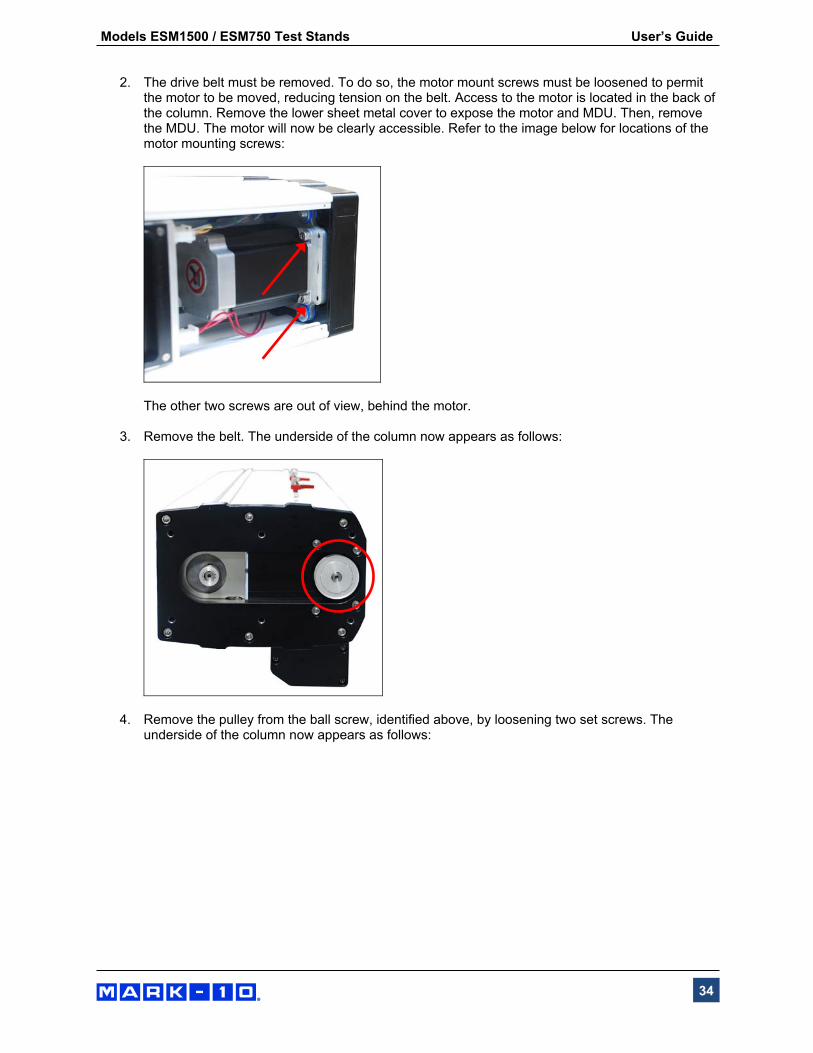
2. The drive belt must be removed. To do so, the motor mount screws must be loosened to permit
the motor to be moved, reducing tension on the belt. Access to the motor is located in the back of the column. Remove the lower sheet metal cover to expose the motor and MDU. Then, remove the MDU. The motor will now be clearly accessible. Refer to the image below for locations of the motor mounting screws:
The other two screws are out of view, behind the motor.
3. Remove the belt. The underside of the column now appears as follows:
4. Remove the pulley from the ball screw, identified above, by loosening two set screws. The underside of the column now appears as follows:

Models ESM1500 / ESM750 Test Stands User’s Guide
35
5. Apply grease to the bearing identified above in the same fashion as the upper bearing.
6. Reassemble, as per above. 9.4 Check for loosened grips and attachments - daily Check to ensure that the grips attached to the force measuring instrument and base plate are firmly secured. Looseness could result in a potentially hazardous situation. 9.5 Check for loosened components – once per month
1. Remove the test sample from the test stand.
2. Turn off power to the test stand and disconnect the power cord. Attempt to loosen subcomponents of the test stand (ex. fasteners, brackets, etc). All components should be firmly attached. If any looseness is detected, stop using the test stand and contact Mark-10 or a distributor for instructions.
9.6 Removing and replacing the Motor Drive Unit (MDU) The MDU is the self-contained location of most of the test stand’s electronics, and is designed for quick removal and replacement in the event of service or repair. If requested by Mark-10 or a distributor to remove and/or replace the MDU, follow these instructions:
1. Disconnect power to the test stand.
2. Remove the screws from the lower rear panel.
3. When the MDU is accessible, disconnect the four connectors and ground wire identified in the image below:
Models ESM1500 / ESM750 Test Stands User’s Guide
36
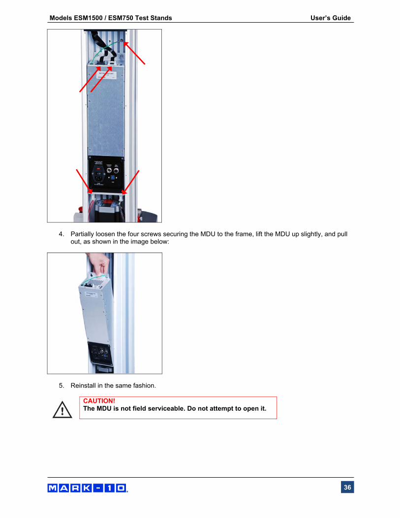
4. Partially loosen the four screws securing the MDU to the frame, lift the MDU up slightly, and pull out, as shown in the image below:
5. Reinstall in the same fashion.
CAUTION! The MDU is not field serviceable. Do not attempt to open it.

Models ESM1500 / ESM750 Test Stands User’s Guide
37
10 SPECIFICATIONS
ESM1500 ESM1500S ESM750 ESM750S
Load capacity:
1,500 lbF [6.7 kN] at < 60 in [1,525 mm]/min
1,000 lbF [4.5 kN] at > 60 in [1,525 mm]/min
750 lbF [3.4 kN] at < 35 in [900 mm]/min
500 lbF [2.3 kN] at > 35 in [900 mm]/min
Maximum travel: 32.0 in [813 mm] 14.2 in [360 mm] 32.0 in [813 mm] 14.2 in [360 mm]
Standard speed range: 0.5 - 24 in/min [10 - 600 mm/min]
Optional speed range: 0.001 - 90 in/min
[0.02 - 2,300 mm/min] 0.001 - 60 in/min
[0.02 - 1,525 mm/min]
Speed setting accuracy: ±0.2%
Travel accuracy: ±0.002 in. per 10 in. [±0.05 mm per 250 mm]
Travel resolution: 0.001 in [0.02 mm]
Limit switch repeatability: ±0.001 in [0.03 mm]
Power: Universal input 80-240 VAC,
50/60 Hz, 450W Universal input 80-240 VAC,
50/60 Hz, 120W
Fuse type: 4A, 3AG, SLO BLO
Weight (test stand only): 198 lb [90 kg] 160 lb [72 kg] 185 lb [84 kg] 150 lb [68 kg]
Shipping weight: 248 lb [113 kg] 206 lb [93 kg] 236 lb [107 kg] 196 lb [88 kg]
Environmental conditions:
40 - 100°F [5 - 40°C], max. 96% humidity, non-condensating

Models ESM1500 / ESM750 Test Stands User’s Guide
38
11 DIMENSIONS in [mm] 11.1 -LC Models
A B
ESM1500LC 51.35
[1304.3]
8.13 - 40.13
[206.4 - 1019.2]
ESM1500SLC 33.89
[860.9]
8.13 - 22.33
[206.4 - 567.1]
ESM750LC 50.85
[1291.6]
8.13 - 40.13
[206.4 - 1019.2]
ESM750SLC 33.39
[848.1]
8.13 - 22.33
[206.4 - 567.1]

Models ESM1500 / ESM750 Test Stands User’s Guide
39
11.2 -FG Models
A B
ESM1500FG 51.35
[1304.3]
5.25 - 37.25
[133.4 - 946.2]
ESM1500SFG 33.89
[860.9]
5.25 - 19.45
[133.4 - 494.0]
ESM750FG 50.85
[1291.6]
5.25 - 37.25
[133.4 - 946.2]
ESM750SFG 33.39
[848.1]
5.25 - 19.45
[133.4 - 494.0]
Models ESM1500 / ESM750 Test Stands User’s Guide
40
Mark-10 Corporation has been an innovator in the force and torque measurement fields since 1979. We strive to achieve 100% customer satisfaction through excellence in product design, manufacturing and customer support. In addition to our standard line of products we can provide modifications and custom designs for OEM applications. Our engineering team
is eager to satisfy any special requirements. Please contact us for further information or suggestions for improvement.
Force and torque measurement engineered better Mark-10 Corporation 11 Dixon Avenue Copiague, NY 11726 USA 1-888-MARK-TEN Tel: 631-842-9200 Fax: 631-842-9201 www.mark-10.com [email protected]
32-1179 REV 0118