Embed Size (px)
Citation preview
Baku, Azerbaijan
IV International Conference “Problems of Cybernetics and Informatics” (PCI'2012), September 12-14, 2012www.pci2012.science.az/2/03.pdf
154
Force Sensors of Sucker Rod Oil Pumps
Gambar Guluyev1, Asif Rzayev2, Yaver Aliyev3, Magomed Rizvanov4
Cybernetics Institute of ANAS, Baku, Azerbaijan [email protected], [email protected], [email protected], [email protected]
Abstract— The present article describes a version of force sensor of sucker rod oil pumps built on the basis of load cell of pocket dynamometer with application of modern pressure sensors, controllers, interfaces and communication protocols.
Keywords— dynamometry; force sensors; load cell; oil extraction; sucker rod pump; traverse
I. INTRODUCTION As of today, basic elements of automation systems of
sucker rod pumping units (SPU) are dynamometry sensors, since only they allow obtaining dynamometer cards containing the information required for analysis of faults of deep-well pump and mode of its operation.
As is known [1], dynamometry sensors are stroke sensor and force sensor. Stroke sensors are designed for determination of motion parameters: suspension points of sucker rod strings – stroke length, time of swing and moments of rod passing the lower and the upper dead points. Force sensors determine the load on the polished rod, which is the weight of liquid raised from the well, the weight of sucker rod strings and friction force in the pump and string combined. Such sensors must work at SPU uninterruptedly for long periods of time in the condition of wide temperature range, endure exposure to moisture, sulfur and other destructive factors, be resistive to overloads and ensure operation in exposion hazard zones.
In the period of SPU operation, numerous force sensors have been developed. Depending on the location and method of placement at SPU, force sensors are classified as follows.
1) Force sensors installed at the beam of SPU. They measure beam deformation, which allows one to estimate the force applied on the polished rod. Operating principle of such sensors is based on measuring the travel distance as a result of deformation of the beam curve. First, beams are known to be manufactured with big safety margin, which reduces sensitivity of this method. Second, deformation level of SPU beam depends not only on the load applied to it but also on the environmental temperature, SPU construction, material of the beam itself. To reduce measurement results to absolute force units one has to calibrate the sensor directly on the SPU. Force sensors on the beam do not provide necessary accuracy of measuring the force on the rod. However, those sensors are easy to install and operate. Those force sensors with analog (DUI – IFS (inductive force sensor)) and frequency (DCLP – LDT (linear displacement transducer))
outputs have been developed in 1960-1970s at SRDI “Neftekhimavtomat” (now SPO “Neftegazavtomat”) [2] and are nowadays operated at different fields of the Azerbaijan Republic as parts of “Gilavar”, “Nur” and “Ayna” telecomplexes [3] despite the above-mentioned shortcomings. It should be noted that those shortcomings are insufficiently noticeable in shallow wells (up to 700 m) and have to be used due to the absence of more acceptable sensors. In deep wells, however, these shortcomings affect dynamometry adversely, which does not provide the necessary quality of control of the technical condition of deep-well pumps.
2) External sensors on the polished rod. They measure longitudinal or lateral deformation of the rod and cannot give information on absolute load values either, which is why they are not applied in stationary systems. “Avton-302” sensors, “Avton SGN Profi” portable dynamograph developed by CJSC “Avtograf” (RF, Ioshkar Ola) [4] can be cited as examples. “Avton SGN Profi” is designed to control the technical condition of sucker rod pumps as a portable device.
3) Sensors installed above the upper traverse. They perceive the load on the rod directly, thereby providing maximum sensitivity of force. However, installing a sensor above the upper requires full dismantling of rod suspension, which is a rather labour-consuming operation. Example of such a sensor is “Loadtrol” sensors manufactured by “Lufkin Automation” (USA) [5]. Despite the simplicity of design, they did not find wide industrial application due to complexity of assembling and installation.
4) Force sensors installed between traverses. They also sense the load on the rod directly and have advantages in assembling and installation on SPU. Most interesting and up-to-date one in this category is DU-04 force sensor of DDS-04 system developed by SPP “Grant” (RF, Republic of Bashkortostan, Ufa) [6,7].
DU-04 tensoresistive force sensor of DDS-04 system has
- the form of a horseshoe, which facilitates its installation on the suspension between traverses;
- microcontroller built in DU-04 sensor, transforming voltage, which is received from the measuring bridge diagonal and proportional to the load, into digital and pulse-width signals, increases performance capacity;
Baku, Azerbaijan
IV International Conference “Problems of Cybernetics and Informatics” (PCI'2012), September 12-14, 2012www.pci2012.science.az/2/03.pdf
155
- RS-485 digital interface unsusceptible to external influences and uncritical to the length of the cable;
- standard current output of 4-20 mA. Thus, it follows from the above-mentioned that
- the optimal location for a force sensor is its placement between traverses of SPU;
- most acceptable sensors among the existing ones today are DU-04 of DDS-04 system.
However, those force sensors have the following shortcomings:
- movable cable between the traverse and the foundation of the pumping unit;
- unavailability of measures for correction of errors caused by change in environmental temperature;
- relatively high cost does not ensure their mass application.
Modern level of development of information technology, microcontrollers, primary meters of nonelectrical quantities, transmission facilities create prerequisites for development of simple and reliable intelligent, stationary force sensors devoid of the above-mentioned sensors.
II. PROBLEM STATEMENT It is necessary to control the applied force at SPU to
100kN within the whole operating temperature range from -40 to +600С. The sensor is to be easy to assemble, mutually replaceable, be able to connect to standard input channels with standard interfaces and data communication protocols of secondary recording equipment. The electronic circuit must be resistant to electromagnetic noise from high-power electric motors and frequency converters located in immediate proximity. Sensor must have low cost for mass application in fields. The problem set is to develop a possible version of block diagram of an intelligent force sensor based on microcontrollers meeting the criteria of low cost, simplicity of assembly, high sensitivity, accuracy, reliability and flexibility.
III. PROBLEM SOLUTION GDM-3 hydraulic dynamometers are known and
manufactured at the present day [8, pp. 186-188]. Measurement range is 40, 80 and 100 kN.
Hydraulic pocket dynamometer is designed for installing rods of PKN-3, PKN-5, PKN-10 types on normal assemblies of rope hangers. To install a dynamograph on a hanger, as well as to uninstall it, 2-3 min stop of the well is required. Force measure device of GDM-3 dynamograph consists of two levers: a hydraulic load cell is built in the upper one. Force measurement range is changed by rearrangement of support rollers of the levers. Force measure device is installed between traverses of the assembly of rope hanger of PKN rod, where tensile force of rods are transformed into force compressing the load cell. In the load cell, this force is transformed into pressure of the liquid under the membrane in the load cell cavity. The problem of force measurement is thereby reduced to measuring pressure of the liquid.
There are many pressure sensors, from which most acceptable ones must be chosen.
Criteria for choice of a pressure meter are as follows:
- pressure range; - low electric power consumption; - proportional conversion of pressure into
electric signal; - high accuracy of conversion of pressure into
electric signal; - change of the original value of the output
signal due to temperature; - low cost; - wide operating temperature range; - high load capacity.
Analysis of available pressure meters resulted in choice of MD 10 – 40 V integral pressure tensoconverter of MD series [9].
To compensate the influence of change in environmental temperature on the value of the output signal of pressure meter, a correction must be made to the measurement result. This requires measuring of temperature.
No strict requirements of measurement accuracy and range for temperature meter are specified in this case. However, its mass and size should be minimal.
Use of widespread microcontrollers in development of industrial products leads to improvement of their engineering and economical performance (reduction of cost, power consumption, size, increased reliability) and allows shortening development time considerable and putting off obsolescence of products. It also gives them crucially new consumer properties (expanded functionality, modifiability, adaptability, etc.). To simplify the scheme, increase reliability and provide flexibility of force sensor, building them on the basis of single-chip microcomputers, i.e. microcontrollers, is suggested. A number of microprocessors and microcontrollers exist, from which most acceptable for the purpose should be chosen.
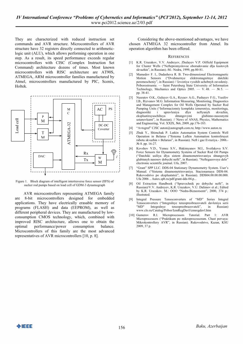
Considering all the above-mentioned, block diagram of intelligent intertraverse force sensor of sucker rod pumps based on load cell of GDM-3 dynamograph (Fig. 1) can be offered.
The block diagram of intelligent intertraverse force sensor (IIFS) consists of the load cell of dynamograph (LC), pressure meter (PM), temperature meter (TM), microcontroller (MC), digital-to-analog coverter (DAC), wireless modem (WM), antenna (A) and power supply (PS) that includes an accumulator (AC) and a direct current to direct current converter (DC-DC Converter).
Successful operation of force sensor in this diagram depends in many ways on the right choice of microcontroller.
Analysis of characteristics and architectures of microcontrollers with allowance for the given task requirements demonstrates that controllers with RISC (Reduced Instruction Set Commands) architecture are the simplest and most appropriate controller for the purpose.
Baku, Azerbaijan
IV International Conference “Problems of Cybernetics and Informatics” (PCI'2012), September 12-14, 2012www.pci2012.science.az/2/03.pdf
156
They are characterized with reduced instruction set commands and AVR structure. Microcontrollers of AVR structure have 32 registers directly connected to arithmetic-logic unit (ALU), which allows performing operation in one step. As a result, its speed performance exceeds regular microcontrollers with CISC (Complex Instruction Set Command) architecture dozens of times. Most known microcontrollers with RISC architecture are АТ90S, ATMEGA, ARM microcontroller families manufactured by Atmel, microcontrollers manufactured by PIC, Scenix, Holtek.
Figure 1. Block diagram of intelligent intertraverse force sensor (IIFS) of
sucker rod pumps based on load cell of GDM-3 dynamograph
AVR microcontrollers representing ATMEGA family are 8-bit microcontrollers designed for embedded applications. They have electrically erasable memory of programs (FLASH) and data (EEPROM), as well as different peripheral devices. They are manufactured by low-consumption CMOS technology, which, combined with improved RISC architecture, allows one to obtain the optimal performance/power consumption balance. Microcontrollers of this family are the most advanced representatives of AVR microcontrollers [10, p. 8].
Considering the above-mentioned advantages, we have chosen ATMEGA 32 microcontroller from Atmel. Its operation algorithm has been offered.
REFERENCES [1] K.R. Urazakov, V.V. Andreyev, Zhulayev V.P. Oilfield Equipment
for Cluster Wells (“Neftepromyslovoe oborudovanie dlja kustovyh skvazhin”, in Russian).-М.: Nedra, 1999, pp.80-81.
[2] Mamedov F. I., Dadasheva R. B. Two-dimensional Electromagnetic Motion Sensors (“Dvuhmernye elektromagnitnye datchiki peremescheniy”, in Russian) // Izvestiya vysshih uchebnyh zavedeniy. Priborostroenie. — Saint Petersburg State University of Information Technology, Mechanics and Optics 2005. — V. 48. — № 5. — pp. 38-41.
[3] Nusratov O.K., Guluyev G.A., Rzyaev A.G., Pashayev F.G., Yusifov I.B., Rizvanov M.G. Information Measuring, Monitoring, Diagnostics and Management Complex for Oil Wells Operated by Sucker Rod Pumping Units (“Informacionniy kompleks izmereniya, monitoringa, diagnostiki i upravleniya dlya neftyanyh skvazhin, ekspluatiruyuschihsya shtangovymi glubinno-nasosnymi ustanovkami”, in Russian). // News of ANAS, Physics, Mathematics and Engineering, Vol. ХХIХ, №6, 2009, pp.176-183.
[4] “Avtograf” CJSC [email protected]; http://www.auton.ru [5] Zhuk Y., Shimchak P. Lutkin Automation System Controls Well
Operation in Belarus (“Sistema Lufkin Automation kontroliruyet rabotu skvazhin v Belarusi”, in Russian). Neft i gaz Evraziya.- 2006.- № 8. pp. 16-27.
[6] Kovshov V.D., Yemec S.V., Hakimyanov M.I., Svetlakova S.V. Force Sensors for Dynamometry Systems of Sucker Rod Oil Pumps (“Datchiki usiliya dlya sistem dinamometrirovaniya shtangovyh glubinnyh nasosov dobychi nefti”, in Russian). “Neftegazovoye delo” electronic scientific journal. Ufa, 2007.
[7] “Grant” SPP LLC. DDS-04 Stationary Dynamometry System. User’s Manual. (“Sistema dinamometrirovaniya. Stacionarnaya DDS-04. Rukovodstvo po ekspluatatsii”, in Russian). DDS04.00.00.00.000. Ufa 2006 .. Autex.spb.ru/pdf/grant-dds-04.p...
[8] Oil Extraction Handbook (“Spravochnik po dobyche nefti”, in Russian)/V.V. Andreyev, K.R. Urazakov, V.U. Dalimov et al.; Edited by K.R. Urazakov. М.: ООО “Nedra-Biznestsentr”, 2000, 374 p.: illustrated.
[9] Integral Pressure Tensoconverters of “MD” Series Integral Tensoconverters (“Integralnye tenzopreobrazovateli davleniya serii "MD" Integralnye tenzopreobrazovateli”, in Russian) www.clo.ru/Catalog/Pribor/IzmRegDavl/izmregdavl.htm
[10] Gumerov R.I. Microprocessors Tutorial. Part 1: AVR Microprocessors (“Praktikum po mikroprocessoram. Chast pervaya: Mikrokontrollery AVR”, in Russian). Rukovodstvo, Kazan, KSU 2009, 37 p.
Load
cel
l PM
TM
DAC
ATM
EGA
-32
MC
WM
RxD ATxD
PSAC
DC-DC Coverter