Embed Size (px)
Citation preview

VERTICAL-€’JANE PENDULUM ABSORBERS FOR MINIMIZING fIELICOPTEX VIBRATORY LOADS
Kenneth B. her Manager, Technical Department
James R. Neff Chief, Dynamics Analysis
Hughes Helicopters Culver City, California
Abstract
This paper discusses the use of pendulum dy- namic absorbers mounted on t h e blade root and operating in the v e r t i c a l plane t o minimize heli- copter vibratory loads.
The paper describes qual i ta t ively the concept of the dynamic absorbers and presents r e s u l t s of ana ly t ica l s tudies showing the degree of reduction i n vibratory loads at ta inable . ence of vertical plane dynamic absorbers on t h e OH-6A hel icopter is a lso discussed.
Operational experi-
Introduction
I n a helicopter it is important t o maintain a low level of vibrat ion f o r two reasons; f i r s t f o r t he comfort of t he c r e w and passengers, and secondly t o minimize maintenance problems. ear ly f l i g h t tests of the OH-6A helicopter (see Figure 1) i n 1463, a high l eve l of 4/rev fuselage vibrat ion w a s encountered primarily during ap- proach t o hover and during high speed f l i gh t .
During
Figure 1. OH-6A Helicopter
Various ana ly t ica l s tudies and experimental pro- grams w e r e conducted i n an e f f o r t t o alleviate t h i s problem. The configuration f i n a l l y adopted w a s vertical-plane pendulum absorbers mounted a t t he roots of t h e main rotor blades (see Figure 2 ) . It is the purpose of t h i s paper t o describe the concept of t he vertical-plane pendulum dynamic absorber and t o present the r e su l t s of analyt ical
studies and f l i g h t tests showing the degree oi re- duction i n vibratory loads attained.
Figure 2. Pendulum Absorbers on OH-6A
Over 3 mil l ion f l i g h t hours of sa t i s fac tory experience have been obtained with the use of vei:icd.-plane pendulum absorbers on t h e OH-6A helicopter and on its commercial counitqiar:, the Model 500 helicopter. This operational experience is a l so discussed i n t h i s paper.
Sources of Fuselage Vibration
The OE-6A helicopter has a 4-bladed main rotor. Table I summarizes the sources of 4/rev fuselage vibration from the main rotor. It can be seen from Table I tha t vertical shears a t the blade root w i t h frequencies of 3/rev, 4/rev, and 5/rev can induce 4/rev vibrations i n the fuselage. 5/rev blade root shears induce &/rev fuselage vi- brations by producing 4/rev hub moments. blade root shear produces a 4/rev hub vertical force. With regard t o in-plane blade root shears, both the 3/rev and the 5/rev component of in-plane root shear produce a 4/rev hub horizontal force. further discussion of t he mechanism by which rotor blades induce vibration i n the fuselage can be found i n Chapter 12 of Reference 1, part icular ly the tables on pages 318 and 319.
The 3/rev and
The 4lrev
A
219
https://ntrs.nasa.gov/search.jsp?R=19740026397 2018-06-12T08:38:51+00:00Z

Table I. Sources of 4/Rev Fuselage
Vibration - 4-Bladed Rotor
Vertical In-Plane
Shear Load Path Shear Load Path
Hub moment3/rev
4/rev Hub vertical
force
5/rev Hub moment
3-rev
5/rev
Hub horizon-
tal force
Hub horizon-
tal force
Table I indicates that there are 5 possible
suu_c_s of e_u_ssiv_ fuselage _irev'' vibration in
the OH-6A helicopter. The next step was to estab-
lish which of the 5 possible sources of vibration
were the most important. Tables II and III pro-
vide an answer to this question.
Table II. OH-6A Main Rotor Blade Natural
Frequencies (per rev) - 100%
RPM - Pendulums Off
Flapwise Chordwise (Cyclic Mode)
2.72 5.14
4.87
In Table II are listed the main rotor blade
flapwlse and chordwise natural frequencies near
the 3/rev through 5/rev frequency. It can be seen
from Table II that the two frequencies most likely
to cause a 4/rev vibration in the fuselage are the
first and second mode flapwlse bending frequencies
which are very close to 3/rev and 5/rev. The
blade chordwlse natural frequency is also close to
5/rev (see Table II). However, Table III con-
firms that the blade flapwise first mode and second
mode frequencies are the primary source of the
vibration problem, in that the fuselage vibration
is much more responsive to hub moments than it isto hub vertical or horizontal forces.
Thus blade vertical bending at a frequency of 4/*
and blade chordwise bending at frequencies of 3/*
and 5/rev can be ignored and the primary sources
vibration can be concluded to be blade flapwise
bending at 3/rev and at 5/rev.
Concept of Vertical-Plane Dynamic Absorbers
Based on the above evaluation, it was con-
cluded that it was necessary to reduce the level
blade 3/rev and 5/rev flapwise bending. After i!
vestigating a number of possible approaches,* it
was decided to pursue the concept of a dynamic w
bration absorber which is discussed in Reference
in the section starting on page 87.
The concept of a uyLL_m±c vibration =U=ULU=L
consists of adding a small mass to a large mass.
The uncoupled natural frequency of the small mas!
(vibration absorber) is chosen to be equal to th,
frequency of the disturbing force. Thus, for th,
OH-6 vibration problem, it was concluded that it
would be necessary to incorporate two dynamic
vibration absorbers; one tuned at 3/rev and the
other tuned at 5/rev. Furthermore, inasmuch as
rotor speed can vary somewhat, it was necessary
that the vibration absorbers maintain the proper
frequency relative to rotor speed. In order to
compllsh this, it was decided to use the concept
a tuned centrifugal pendulum discussed on page 2
of Reference 2. This concept has been used for
many years to minimize the torsional vibrations
piston engines. Thus, the final configuration t
evolved consisted of two pendulums mounted at th
roots of the main rotor blades; one tuned to a
natural frequency of 3/rev, the other tuned to a
natural frequency of 5/rev. Inasmuch as the she
force and blade motion which were to be minimize
were in the vertical plane, the dynamic pendulum
were oriented to oscillate in the vertical plane
Figure 3 shows schematically the pendulum
motion relative to the blade deflection for the
case of response to 3/rev excitation. It is ev_
dent that the centrifugal force from the pendulu
is directed such as to cancel most of the trans-
verse shear due to blade modal response. The ne
result is a significant reduction in the 3/rev
vertical shear force transmitted to the hub.
Table III. OH-6A Cockpit Response to Rotor
Excitation, V = I00 Knots
(No Pendulums Installed)
Excitation
Force, If
Unit Response
at Cockpit,
In/sec/ib
Response at
Cockpit,in/sec
4/Rev
Vertical
130
.0012
.16
4/Rev
Pitching;
Moment
*86
.00265
.23
4/Rev
Rolling
Moment
*'112
.0106
1.19
4/Rev
Longitudinal
Shear
10
.00193
.019
* Blade vertical shear force causing pltch_ng moment.
** Blade vertlcal shear force causing rolling moment.
4/Rev
Latera
Shear
35
.0077
.27
* Other approaches evaluated included providing
control of blade first and second mode natural
frequencies by means of anti-node weights and b}
use of preloaded internal cables. Flight tests
not show these methods to be sufficiently effect
Hub-mounted vertical plane pendulums were flown
proved to be effective, but considerations of dl
and weight were unfavorable for this configuratS
Fuselage-mounted non-rotatlng dampers were elimJ
nated because of the difficulty of tuning to a
sufficiently wide range of frequency. Fuselage-
mounted centrifugal pendulum dampers were con-
sidered impractical from the standpoint of spac_
requirements and mechanical complexity.
220
1.0
.B
.6
.4
.2
MODAL 0
DEFLECTION -.2
-.4
-.6
-.8
-1.00 20 4O 60 80 100 120 140 160
BLADESTATION - INCHES
Analytical Studies
Analytical studies were conducted to investi-
gate the effectiveness of vertical plane pendulum
absorbers in minimizing the blade vertical root
shears and the fuselage vibration levels. The re-
suits of these analytical studies are presented in
Table IV for the OH-6A at a forward speed of 100
knots. It can be seen from Table IV that the addi-
tion of the 31rev pendulum dynamic absorber reduces
the 3/rev vertical root shear by 75%. The addition
of the 5/rev vertical dynamic absorber reduces the
5/rev vertical root shear by 85%. The net result
is a 72Z reduction in the vibration level in the
crew col_ar tment.
Figure 3. Pendulum Motion Schematic
Basic Physical Parameters
The pendulum configuration that was estab-
lished, flight tested, and put into service has the
following characteristics:
3/rev pendulum
weight: 1.8 ib
actual mass ratio: .048
modal mass ratio: .64
Table IV.
Damped Blade l 23 I 6 l
Effect of Vertical-Plane Pendulum
Absorbers on Root Shear and
Cockpit Vibration - OH-6A
(Analytical Studies, I00 Knots)
Cockpit ]
Vibration, amp_
5/rev pendulmn
weight: .7 ib
modal mass ratio: .52
The pivot axis of both pendulums is located at
15% of the blade span from the center line of the
rotor, and 29% of the chord from the leading edge.
This location was chosen so that existing bolts in
the blade root fitting could be used, thus pre-
venting the introduction of stress concentration
points into critical sections of the blade.
Analysis indicates that a location further out-
board would be more favorable, but this has not
been confirmed by test, because of the structural
considerations cited above.
Damping of the pendulums due to friction in
the pivot bearings is estimated to be equivalent to
I% of the critical viscous damping _atlo for the
3/rev pendulums at an amplitude of _16 °. For the
5/rev pendulums at the same amplitude the damping
ratio is 3Z of critical.
The dampers are 'bench" tuned, by means of
shims, to the correct pendular frequency within
0.5% of the length of the 3/rev pendulums and to
within 1% of the length of the 5/rev pendulums.
The effect of mis-tuning has bsen investigated only
to the extent of showing that - one shim does not
have a consistently observable effect on either
qualitative or measured cockpit vibration.
The _nalytical procedure used to achieve the
results of Table IV is designated SADSAM. This
analytical procedure is described in Reference 3
and was conducted in two steps. In the first step,
SADSAMwas used to calculate the blade root shears
for a forward speed of I00 knots both without and
with the pendulum absorbers. The analytical model
of the blade used in this step was a ten station,
fully coupled representatlonwith aerodynamic ex-
citation forces obtained from flight measured
pressure distributions (Reference 4). In the second
phase of the analysis, a 41 degree-of-freedom fuse-
lagemathematical model, adjusted to agree with
shake test results, was analyzed using SADSAM to
obtain the effect of the resulting hub moments on
the response in the crew compartment.
Flight Test Results
The favorable analytical results referred to
above led to a decision to fabricate an experi-
mental set of pendulum dynamic absorbers. These
absorbers, similar to those shown in Figure 2, were
installed on the flight test OH-6A helicopter.
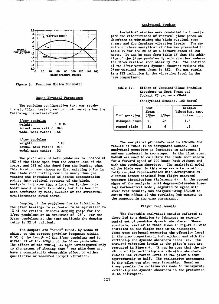
Tests were conducted measuring the vibration level
in the crew compartment, both without and with the
vertical-plane dynamic absorbers installed. The
measured vibration levels at the pilot's seat are
presented in Figure 4. It can be seen that the ad-
dition of the vertlcal-plane vibration absorbers
reduces the vibration level at the pilot's seat
approximately in half. The qualitative assessment
by the pilot was also very favorable. Based on
these results the decision was made to incorporate
vertlcal-plane dynamic absorbers in the production
OH-6A helicopter.
221

2.0
1.8
1.6
1.4
VIBRATION 1.2
VELOCITY, 1.0IN./SEC .8
.6
.4
.2
070 80 90 100 110 120 130
Vi, KNOTS
Figure 4. Measured Vibration Level of OH-6AWithout and With Pendulum Absorbers
............ _=_=L,_= on OH-6A
The vertical plane pendulum absorbers were
incorporated on all production OH-6A helicopters
and on its commercial counterpart, the Model 500.
Over 3,000,000 flight hours have been accumulated.
Up to a servihe llfe of between 300 and 600 hours,
the absorbers did a good Job of controlling the
vibration level of the helicopter. However, after
approximately 300 to 600 hours of service, the
bearings and shafts on which the absorbers are
mounted exhibited excessive wear, resulting in in-
creased vibration level in the helicopter. Re-
placement of the bearings and shafts generally
returned the helicopter to an acceptable level of
vibration. The premature wearing of the bearings
and shafts was attributed to the high PV value.
Laboratory tests were conducted on various
combinations of bearings and shaft types with the
objective of selecting a combination that would
have the desired service life of 1200 hours. It
was also required that any new shaft and/or bearing
materials be interchangeable with the initial pro-
duction bearings and shafts. Thus no change in
geometry was permitted.
The results of these laboratory tests showed
that all combinations of shafts and bearings tests,
with the exception of one, were inferior to the
original configuration (which consisted of a
bearing consisting of a stainless steel outer race
with a bonded self-lubricating teflon liner, and a
stainless steel shaft with an 8 RMS finish). The
only improved configuration consisted of an Astro
AM1282 bearing, which was specially made for the
laboratory test operating on the original shaft.
This Astro bearing is currently under considerationfor retrofit.
Conclusions
This paper has demonstrated both analytically
and by operational experience that the use of pen-
dulum dynamic absorbers, mounted on the blade root
and operating in the vertical plane, can success-
fully reduce helicopter vibratory loads. The
specific application on an OH-6A helicopter was a
222
4-bladed rotor with the pendulums tuned to 3/rev
and 5/rev. The pendulums reduced the vibration
level in the cockpit to approximately one half of
the level that existed prior to the installation of
the pendulums.
References
1. Gessow, Alfred and Myers, Garry C., "Aerodyna-
mics of the Helicopter," The MacMillan
Company, New York, 1952.
2. Den Hartog, J. P., "Mechanical Vibrations,"
Fourth Edition, McGraw-Hill Book Co., New York,
1956.
3. Peterson, L., "SADSAM User's Manual," The
MacNeal-Schwendler Corp., 7442 N. Figueroa St.,
Los Angeles, CA, Report MSR-10, December 1970.
4. Scheiman, James, "A Tabulation of Helicopter
Rotor Blade Differential Pressures, Stresses,
and Motions as Measured in Flight," NASA
TMX-952, March 1964.
Acknowledgment
The contribution of R. A. Wagner and other
Hughes personnel to the development of the vertical-
plane pendulum absorbers is hereby acknowledged.