Embed Size (px)
Citation preview

For version v04.00.51

PROGRAMMER'S GUIDE FOR v04.00.51
3
PROGRAMMER'S GUIDE FOR v04.00.51
Table of contents1 INTRODUCTION......................................................................................................................................................................... 5
1.1 References .......................................................................................................................................................................... 5 1.2 Notices ................................................................................................................................................................................ 5
2 CONTROLING LIVECORE™ ......................................................................................................................................................... 6 2.1 Introduction ........................................................................................................................................................................ 6 2.2 Physical interfaces ............................................................................................................................................................... 6 2.3 Protocol ............................................................................................................................................................................... 7 2.4 Command principle and structure ...................................................................................................................................... 8 2.5 Commands sequencing ..................................................................................................................................................... 11 2.6 Command indexes and Command values ......................................................................................................................... 12 2.7 Multiple controllers........................................................................................................................................................... 12 2.8 Multiple machines (Additive configuration) ..................................................................................................................... 12
3 COMMON LIVECORE™ USE CASES .......................................................................................................................................... 13 3.1 Establishing a connection with a LiveCore™ ..................................................................................................................... 14 3.2 Loading Presets from Memory (to a single screen) .......................................................................................................... 17 3.3 Loading Presets from Master Memory (to multiple screens) ........................................................................................... 20 3.4 Changing the source displayed in a layer .......................................................................................................................... 23 3.5 Changing a native background .......................................................................................................................................... 24 3.6 Single Screen TAKE : Transitioning the Preview content to the Program (single screen) ................................................. 25 3.7 Global TAKE: Transitioning the Preview content to the Program (multiple screens) ....................................................... 27 3.8 Configuring the Monitoring full screen mode ................................................................................................................... 30 3.9 Configuring the Monitoring Mosaic mode ........................................................................................................................ 32 3.10 Selecting a Monitoring preset ........................................................................................................................................... 34 3.11 Loading a “Confidence monitor” preset from memory .................................................................................................... 35 3.12 Using snapshots ................................................................................................................................................................ 35 3.13 Shutting down or rebooting the LiveCore™ device ........................................................................................................... 36 3.14 Waking the LiveCore™ device (over LAN) ......................................................................................................................... 36 3.15 GPI General Purpose Input ................................................................................................................................................ 38 3.16 GPO General Purpose Output (Free mode) ...................................................................................................................... 40 3.17 TALLY status ...................................................................................................................................................................... 42
4 NOTES ..................................................................................................................................................................................... 43 4.1 Using this document ......................................................................................................................................................... 43
4
PROGRAMMER'S GUIDE FOR v04.00.51
Pictures indexPicture 1 : RJ45 LEDs colors definition ...................................................................................................................................................... 6 Picture 2 : Write command example ........................................................................................................................................................ 8 Picture 3 : Read command example ......................................................................................................................................................... 9 Picture 4 : Valid answer structure ............................................................................................................................................................. 9 Picture 5 : Error answer example ............................................................................................................................................................ 10 Picture 6 : Write command sequence ..................................................................................................................................................... 11 Picture 7 : Read command sequence ...................................................................................................................................................... 11 Picture 8 : Example of connection establishment................................................................................................................................... 16 Picture 9 : Loading Preset from memory - Web RCS............................................................................................................................... 17 Picture 10 : Example of memorized preset recall ................................................................................................................................... 19 Picture 11 : Loading Preset from Master Memory - Web RCS ................................................................................................................ 20 Picture 12 : Example of Master Memory preset recall ........................................................................................................................... 22 Picture 13 : Changing layer source - Web RCS ........................................................................................................................................ 23 Picture 14 : Example of Preview layer source change ............................................................................................................................ 23 Picture 15 : Changing a native background - Web RCS ........................................................................................................................... 24 Picture 16 : Example of changing a native background Set .................................................................................................................... 24 Picture 17 : Example of Single Screen TAKE ............................................................................................................................................ 26 Picture 18 : Example of Global TAKE ....................................................................................................................................................... 28 Picture 19 : Example of Monitoring full screen mode configuration ...................................................................................................... 31 Picture 20 : Example of Monitoring Mosaic mode configuration ........................................................................................................... 33 Picture 21 : Example of Monitoring preset recall ................................................................................................................................... 34 Picture 22 : Web RCS DashBoard – MAC Address ................................................................................................................................... 37 Picture 23 : Sets GPI ‘Take’ mode for screen 4 and reads availability flag and status ............................................................................ 39 Picture 24 : Reads availability flag, sets GPO ‘FREE’ mode and activates the GPO output ..................................................................... 41 Picture 25 : PDF reader, Previous and Next page buttons ...................................................................................................................... 43
5
PROGRAMMER'S GUIDE FOR v04.00.51
1 INTRODUCTION
This document provides information and guidance to control LiveCore™ products directly from controllers without using the standard Web RCS. A basic knowledge of the machine is necessary, using the Web RCS.
TPP stands for Third Party Protocol.
1.1 References
(on ANALOG WAY web site)
LiveCore_TPP_commands_for_v04-00-51.xls (LiveCore™ v04.00.51 TPP command set)
LiveCore™ v04.00.51 firmware updater
Ascender 48 - ASC4806 User Manual
Ascender 48 - ASC4806 Quick Start Guide
1.2 Notices
Pictures and drawings are non-contractual.
Specifications are subject to change without prior notice.
6
PROGRAMMER'S GUIDE FOR v04.00.51
2 CONTROLING LIVECORE™
2.1 Introduction
LiveCore™ products are usually controlled by the user friendly Web RCS or by the VERTIGE high-end remote controller, but a programming interface is also provided for automation applications.
A good practice is to setup the machine with the Web RCS and then control it with a few basic commands like “preset recalling” and “layer input change”.
2.2 Physical interfaces
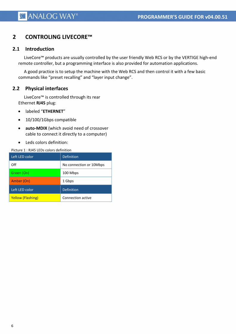
LiveCore™ is controlled through its rear Ethernet RJ45 plug:
labeled “ETHERNET”
10/100/1Gbps compatible
auto-MDIX (which avoid need of crossover cable to connect it directly to a computer)
Leds colors definition:
Picture 1 : RJ45 LEDs colors definition
Left LED color Definition
Off No connection or 10Mbps
Green (On) 100 Mbps
Amber (On) 1 Gbps
Left LED color Definition
Yellow (Flashing) Connection active
7
PROGRAMMER'S GUIDE FOR v04.00.51
2.3 Protocol
Supported protocol is TCP/IP, parameters can be set up with front panel or Web RCS configuration menus.
Default values are:
Protocol : TCP
DHCP client : no
IP address : 192.168.2.140
IP mask : 255.255.255.0
Gateway : none
TPP port : 10600
Note : the simultaneous connection number is limited to 5.
8
PROGRAMMER'S GUIDE FOR v04.00.51
2.4 Command principle and structure
2.4.1 LiveCore™ control principle
LiveCore™ functionalities are controlled through commands. Those commands allow reading or writing in machine registers.
The product should be considered as a state machine controlled by writing to its registers. Writing into registers modifies machine state. Current state of the machine is always available by reading its registers.
Registers structure and size can range from a simple bit up to multidimensional array of 32 bits words. As a result, writing in such a multidimensional register requires providing indexes values in addition to the register value.
Each register have a unique name, only made of five letters, upper case or lower case. (2 exceptions having 1 letter name command)
A command is made only of displayable ASCII characters (ranging from 0x21 up to 0x7E) and is ended with a LF character (ASCII 0x0A) that will be represented hereafter with the character LF.
Commands are of 2 types: read commands or write commands, using the same syntax.
a write command is made of indexes values, followed by the register value, followed by the register name and ended by the character L
F.
a read command uses exactly the same syntax, except the register value that is omitted.
2.4.2 Write command structure
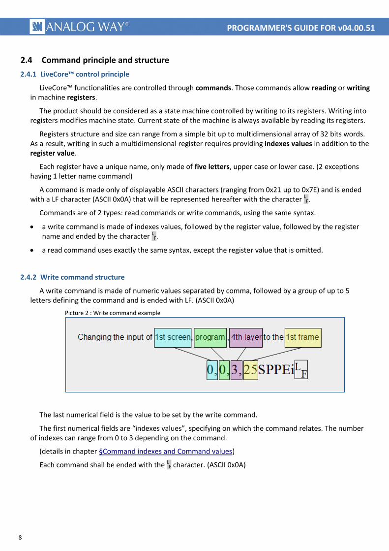
A write command is made of numeric values separated by comma, followed by a group of up to 5 letters defining the command and is ended with LF. (ASCII 0x0A)
Picture 2 : Write command example
The last numerical field is the value to be set by the write command.
The first numerical fields are “indexes values”, specifying on which the command relates. The number of indexes can range from 0 to 3 depending on the command.
(details in chapter §Command indexes and Command values)
Each command shall be ended with the LF character. (ASCII 0x0A)
9
PROGRAMMER'S GUIDE FOR v04.00.51
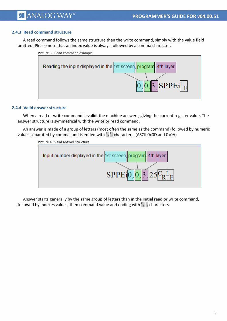
2.4.3 Read command structure
A read command follows the same structure than the write command, simply with the value field omitted. Please note that an index value is always followed by a comma character.
Picture 3 : Read command example
2.4.4 Valid answer structure
When a read or write command is valid, the machine answers, giving the current register value. The answer structure is symmetrical with the write or read command.
An answer is made of a group of letters (most often the same as the command) followed by numeric values separated by comma, and is ended with CR LF characters. (ASCII 0x0D and 0x0A)
Picture 4 : Valid answer structure
Answer starts generally by the same group of letters than in the initial read or write command,
followed by indexes values, then command value and ending with CR LF characters.

10
PROGRAMMER'S GUIDE FOR v04.00.51
2.4.5 Error answer
When an invalid read or write command string is received, the machine ignores it, answers with the previous value (unless in case of command error) and immediately answers with one of the following error string.
Picture 5 : Error answer example
Error message structure:
An error message is made of the capital letter E followed by a 2 digits value depending on the error and is ended with CR LF characters. (ASCII 0x0D and 0x0A)
Here are returned error code and conditions covered:
E10: means “command name error”. It is usually due to a command field (i.e. five letters) that does not match any legal command string.
E11: means “index value out of range”. It is usually due to a wrong index value.
E12: means “index number error”. It is usually due to an incorrect number of indexes, too or not enough.
E13: means “value out of range”. It is usually due to a wrong value in a writing command.
11
PROGRAMMER'S GUIDE FOR v04.00.51
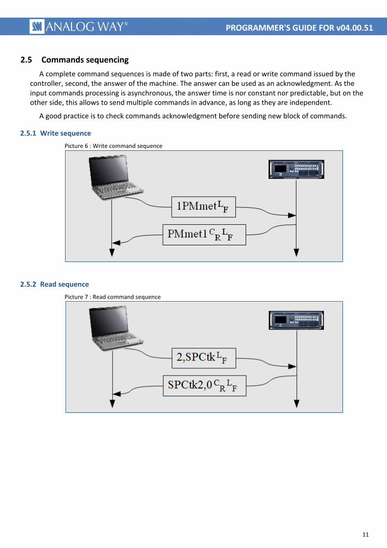
2.5 Commands sequencing
A complete command sequences is made of two parts: first, a read or write command issued by the controller, second, the answer of the machine. The answer can be used as an acknowledgment. As the input commands processing is asynchronous, the answer time is nor constant nor predictable, but on the other side, this allows to send multiple commands in advance, as long as they are independent.
A good practice is to check commands acknowledgment before sending new block of commands.
2.5.1 Write sequence
Picture 6 : Write command sequence
2.5.2 Read sequence
Picture 7 : Read command sequence
12
PROGRAMMER'S GUIDE FOR v04.00.51
2.6 Command indexes and Command values
As explained in chapter §LiveCore_control_principle, LiveCore™ commands allow reading or writing values in multidimensional registers. For these, indexes values must be supplied. If a register is not multidimensional, its reading or writing commands does not need indexes values.
Indexes values: Depending on the command, you can have to specify from 0 to 3 indexes values. They indicate on which the command relates. For example, the “OSCREEN_MAX_LAYERS” command which gives the number of layers in a screen, requires an index value to indicate the desired device’s screen.
No wildcard exists; all required indexes values shall be supplied. Some indexes values have names starting with “DIM_”, meaning dimension. For example, the ”VER_UPDATER” command giving the device firmware version, always requires a “DIM_DEVICE” index value indicating the master or slave device (used in an additive configuration), even there is only one device (in this case, the master index value shall always be provided).
Indexes values are detailed in the “LiveCore_TPP_commands_for_v04-00-51.xls” document.
Command value: This is the register value. In a write command, it indicates the new value that you want to be applied. In a read answer, it indicates the current state of the command (current register value). A write command is only distinguished from a read command due to the presence of the numerical command value just before the command letters.
A value written in a register remains until modified by a new write command or by the device itself. This allows options to be written only once (see preset recall filter option example).
All registers have a default value, noted in the detailed tables.
You must be careful on value range, which depends on multiple factors, like device type, device configuration or current situation. Value range have names starting with “ENUM_”, else, if no enumeration name exist, value must be comprise between given “min value” and “max value”.
Commands values are detailed in the “LiveCore_TPP_commands_for_v04-00-51.xls” document.
2.7 Multiple controllers
Multiple controllers are allowed, limited to 5, with TCP protocol.
No priority exist, in case of simultaneous writing of the same command, the machine applies the last received. In all cases, controllers must take in account the last answer received.
User must particularly be careful with compound commands. For example the “Preset recalling” action requires sending at least 3 commands (origin memory number, destination screen number and destination preset number) before launching the recall. This can cause intermixing commands with 2 simultaneously sending controllers.
2.8 Multiple machines (Additive configuration)
In this configuration, the controller shall only control the “master” device. This means that index value 0 shall always be supplied when a “DIM_DEVICE” index is required.

13
PROGRAMMER'S GUIDE FOR v04.00.51
3 COMMON LIVECORE™ USE CASES
The following common actions can be remotely controlled:
Establishing a connection with a LiveCore™, comprising :
◦ Socket opening
◦ Device type checking
◦ Command set version checking
◦ LiveCore™ registers read back
Loading Presets from Memory (to a single screen)
Loading Presets from Master Memory (to multiple screens)
Changing the source displayed in a layer
Changing a native background
Single Screen TAKE : Transitioning the Preview content to the Program (single screen)
Global TAKE : Transitioning the Preview content to the Program (multiple screens)
Monitoring
◦ Configuring the Monitoring full screen mode
◦ Configuring the Monitoring Mosaic mode
◦ Selecting a Monitoring preset
Using snapshots
Shutting down or rebooting the LiveCore™ device
Waking the LiveCore™ device (over LAN)
Controlling GPIO
◦ General Purpose Input
◦ General Purpose Output (Free mode)
14
PROGRAMMER'S GUIDE FOR v04.00.51
3.1 Establishing a connection with a LiveCore™
3.1.1 Usage
This example gives you the proper way to establish the connection with a LiveCore™ device. It is made of four recommended steps: socket opening, device type checking, command set version checking and LiveCore™ registers read back.
3.1.2 Summary of the commands sequence
socket opening initial step, TCP/IP connection.
device type checking verifying that the expected device is connected.
command set version checking verifying of the matching between controller and machine.
LiveCore™ registers read back retrieval of the machine current state.
3.1.3 Detailed commands sequence
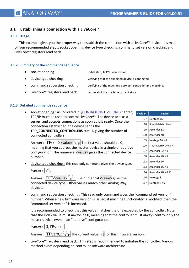
socket opening : As indicated in §CONTROLING LIVECORE chapter, TCP/IP must be used to control LiveCore™. The device acts as a server, and accepts connections as soon as it is ready. Once the connection established, the device sends the TPP_CONNECTED_CONTROLLERS status, giving the number of connected controllers.
Answer : TPcon0,<value>C
RL
F The first value should be 0,
meaning that you address the master device in a single or additive configuration. The numerical <value> gives the connected device number.
device type checking : This read only command gives the device type.
Syntax : ?L
F
Answer : DEV<value> C
RL
F The numerical <value> gives the
connected device type. Other values match other Analog Way devices.
command set version checking : This read only command gives the “command set version” number. When a new firmware version is issued, if machine functionality is modified, then the “command set version” is increased.
It is recommended to check that this value matches the one expected by the controller. Note that the index value must always be 0, meaning that the controller must always control only the master device, even in an “additive” configuration.
Syntax : 0,TPverLF
Answer : TPver0,2 C
RL
F The current value is 3 for this firmware version.
LiveCore™ registers read back : This step is recommended to initialize the controller. Various method exists depending on controller software architecture.
<value> device
97 NeXtage 16
98 SmartMatriX Ultra
99 Ascender 32
100 Ascender 48
105 NeXtage 16 4K
106 SmartMatriX Ultra 4K
107 Ascender 32 4K
108 Ascender 48 4K
112 Ascender 16
113 Ascender 16 4K
114 Ascender 48 4K PL
116 NeXtage 8
117 NeXtage 8 4K
15
PROGRAMMER'S GUIDE FOR v04.00.51
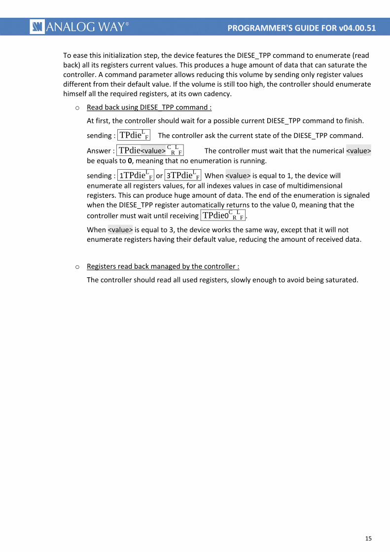
To ease this initialization step, the device features the DIESE_TPP command to enumerate (read back) all its registers current values. This produces a huge amount of data that can saturate the controller. A command parameter allows reducing this volume by sending only register values different from their default value. If the volume is still too high, the controller should enumerate himself all the required registers, at its own cadency.
o Read back using DIESE_TPP command :
At first, the controller should wait for a possible current DIESE_TPP command to finish.
sending : TPdieL
F The controller ask the current state of the DIESE_TPP command.
Answer : TPdie<value> C
RL
F The controller must wait that the numerical <value>
be equals to 0, meaning that no enumeration is running.
sending : 1TPdieL
F or 3TPdieL
F When <value> is equal to 1, the device will
enumerate all registers values, for all indexes values in case of multidimensional registers. This can produce huge amount of data. The end of the enumeration is signaled when the DIESE_TPP register automatically returns to the value 0, meaning that the
controller must wait until receiving TPdie0C
RL
F .
When <value> is equal to 3, the device works the same way, except that it will not enumerate registers having their default value, reducing the amount of received data.
o Registers read back managed by the controller :
The controller should read all used registers, slowly enough to avoid being saturated.
16
PROGRAMMER'S GUIDE FOR v04.00.51
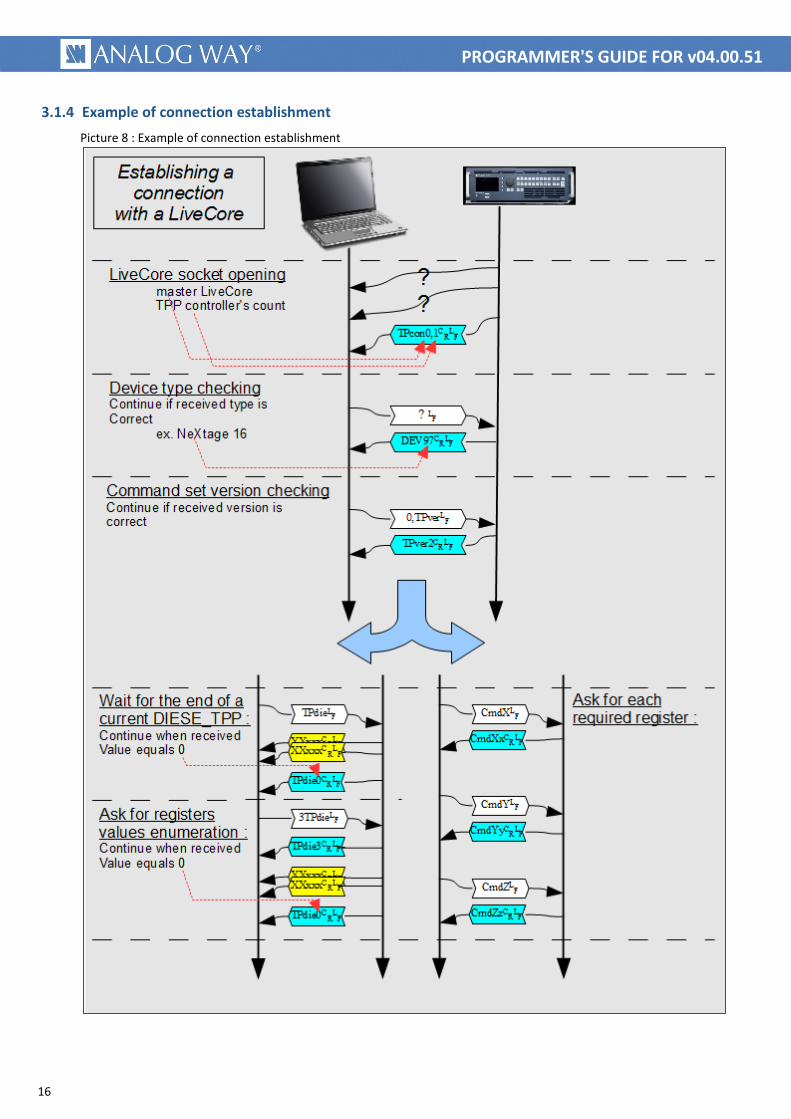
3.1.4 Example of connection establishment
Picture 8 : Example of connection establishment

17
PROGRAMMER'S GUIDE FOR v04.00.51
3.2 Loading Presets from Memory (to a single screen)
3.2.1 Usage
Picture 9 : Loading Preset from memory - Web RCS
A simple way to control a LiveCore™ product is to record the entire screen contents in its memories, using the Web RCS, during the initial setup. These memories can then be remotely recalled by a controller.
The “recall Preset from memory” action is made of multiple commands, used to set parameters like memory number, destination screen, filters, options and is ended with the load command. The sending order of the parameters is free, it must be done before starting the loading.
Parameters that do not change don't need to be sent each time.
A programmable filter allows selection of recalled elements, like source or layers positions and sizes, etc. It can be used, for example to include or exclude displayed input from memory recall.
An option allows scaling of memorized preset in order to adapt it to a screen of different size. (for example due to covering size change)
3.2.2 Summary of the commands sequence
Set the recalling filter (optional, can be settled only once after powering)
Set scale enable (optional, can be settled only once after powering)
Set the origin memory number (order does not matter, must be sent before “Start the copy”)
Set the destination screen number : (order does not matter, must be sent before “Start the copy”)
Set the Program/Preview destination (order does not matter, must be sent before “Start the copy”)
Start the copy (must be sent last)
Wait the end of the copy (optional, typical copy duration is a few 1/10s)
As explained at §LiveCore control principle, values written in registers remain active until changed. This allows sending only once the parameters that don’t change while power remains on. This implies also that order is not important but parameters must be settled before executing the copy command.

18
PROGRAMMER'S GUIDE FOR v04.00.51
3.2.3 Detailed commands sequence
Set the recalling filter : This command allows including or excluding preset elements from recalling.
Syntax : <filter value>PMcatL
F
The <filter value> can be calculated by adding the values associated with each element to include (not filtered elements).
Allowed values are from 0 up to 4095.
Note that adding all elements gives the value 4095, that means “include all elements”, no filtering occurs.
Example 1 : 4095PMcatL
F recall all elements.
Example 2 : 4094PMcatL
F recall all elements except layers
sources.
Set scale enable : This command allows automatic resizing of layers due to changes in screen size. (for example due to covering size change)
Syntax : <value>PMlseL
F <value> can be 0 to disable or 1 to enable resizing.
Set the origin memory number : This command sets the memory number to recall.
Syntax : <value>PMmetL
F The <value> is the Web RCS memory number minus 1, allowed values are
from 0 up to 143.
Set the destination screen number :
Syntax : <value>PMscf L
F The <value> is the Web RCS screen number minus 1, allowed values
are from 0 up to 7, depending on machine and configuration.
Set the Program/Preview destination value :
Syntax : <value>PMprfL
F The destination <value> is 0 for Program or 1 for Preview.
Start the copy : Once all previous parameters are set, start the copy process.
Syntax : 1PMloaL
F Only value 1 is allowed, machine will immediately acknowledge the command,
then will answer the same command with the 0 value after the end of the copy.
Wait the end of the copy : This step is optional. End of copy is signaled by answering the PMloa command with value 0. This answer cannot arrive later than a few 1/10s.
Answer : PMloa0 C
RL
F Wait this answer for a few 1/10s max.
element to recall value
layers sources 1
layers positions and sizes 2
layers transparencies 4
layers cropping parameters 8
layers borders 16
layers transitions 32
layers effects 64
layers timings 128
speed parameters 256
Flying curve parameters 512
native background parameters 1024
Cut & Fill parameters 2048
All elements 4095
19
PROGRAMMER'S GUIDE FOR v04.00.51
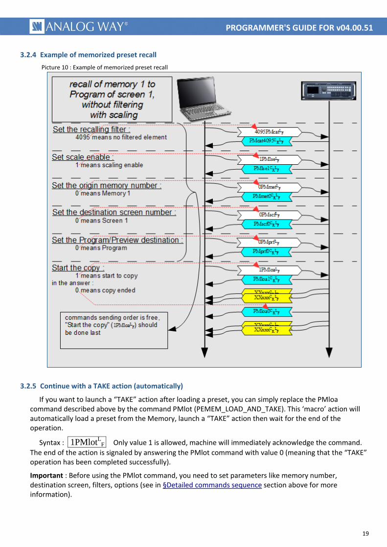
3.2.4 Example of memorized preset recall
Picture 10 : Example of memorized preset recall
3.2.5 Continue with a TAKE action (automatically)
If you want to launch a “TAKE” action after loading a preset, you can simply replace the PMloa command described above by the command PMlot (PEMEM_LOAD_AND_TAKE). This ‘macro’ action will automatically load a preset from the Memory, launch a “TAKE” action then wait for the end of the operation.
Syntax : 1PMlotL
F Only value 1 is allowed, machine will immediately acknowledge the command.
The end of the action is signaled by answering the PMlot command with value 0 (meaning that the “TAKE” operation has been completed successfully).
Important : Before using the PMlot command, you need to set parameters like memory number, destination screen, filters, options (see in §Detailed commands sequence section above for more information).
20
PROGRAMMER'S GUIDE FOR v04.00.51
3.3 Loading Presets from Master Memory (to multiple screens)
3.3.1.1 Usage
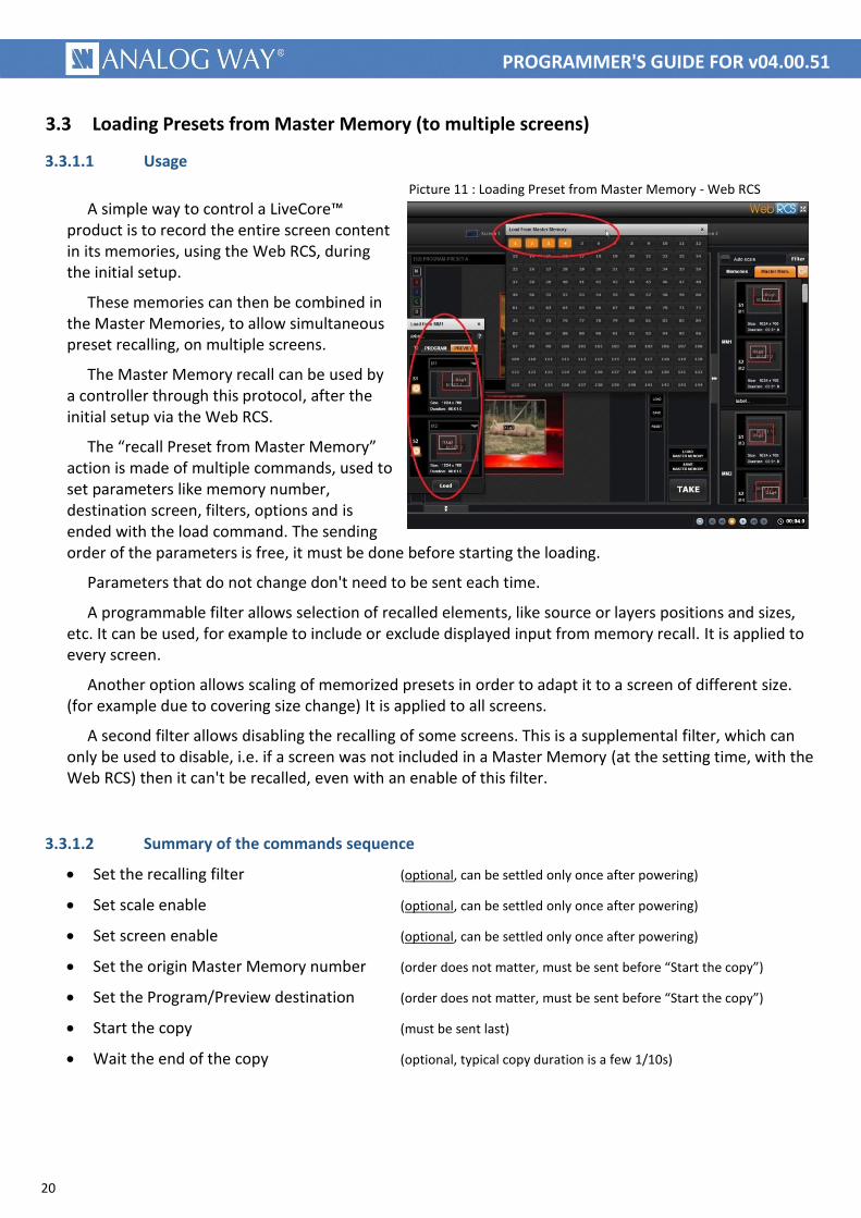
Picture 11 : Loading Preset from Master Memory - Web RCS A simple way to control a LiveCore™
product is to record the entire screen content in its memories, using the Web RCS, during the initial setup.
These memories can then be combined in the Master Memories, to allow simultaneous preset recalling, on multiple screens.
The Master Memory recall can be used by a controller through this protocol, after the initial setup via the Web RCS.
The “recall Preset from Master Memory” action is made of multiple commands, used to set parameters like memory number, destination screen, filters, options and is ended with the load command. The sending order of the parameters is free, it must be done before starting the loading.
Parameters that do not change don't need to be sent each time.
A programmable filter allows selection of recalled elements, like source or layers positions and sizes, etc. It can be used, for example to include or exclude displayed input from memory recall. It is applied to every screen.
Another option allows scaling of memorized presets in order to adapt it to a screen of different size. (for example due to covering size change) It is applied to all screens.
A second filter allows disabling the recalling of some screens. This is a supplemental filter, which can only be used to disable, i.e. if a screen was not included in a Master Memory (at the setting time, with the Web RCS) then it can't be recalled, even with an enable of this filter.
3.3.1.2 Summary of the commands sequence
Set the recalling filter (optional, can be settled only once after powering)
Set scale enable (optional, can be settled only once after powering)
Set screen enable (optional, can be settled only once after powering)
Set the origin Master Memory number (order does not matter, must be sent before “Start the copy”)
Set the Program/Preview destination (order does not matter, must be sent before “Start the copy”)
Start the copy (must be sent last)
Wait the end of the copy (optional, typical copy duration is a few 1/10s)

21
PROGRAMMER'S GUIDE FOR v04.00.51
3.3.1.3 Detailed commands sequence
Set the recalling filter : This command allows including or excluding preset elements from recalling.
Syntax : <filter value>PMcatL
F
The <filter value> can be calculated by adding the values associated with each element to include (not filtered elements). Legal values are from 0 up to 4095.
Note that adding all elements give the value 4095, that means “include all elements”, no filtering occurs.
Example 1 : 4095PMcatL
F recall all elements.
Example 2 : 4095PMcatL
F recall all elements except layers
sources.
Set scale enable : This command allows automatic resizing of layers due to changes in screen size. (for example due to covering size change)
Syntax : <value>PMlseL
F <value> can be 0 to disable or 1 to enable resizing.
Set screen enable : This command allows to disable the recalling on some screens.
Syntax : <MasterMem>,<Screen>,<value>PSsseL
F <MasterMem> is the “Master Memory” number.
<Screen> is the destination screen to be included or excluded from the memory recall.
<value> can be 0 to disable recalling on that screen or 1 to enable it.
Set the origin Master Memory number : This command sets the Master Memory number to recall.
Syntax : <value>PSmetL
F The <value> is the Web RCS Master Memory number minus 1, legal values
are from 0 up to 143.
Set the Program/Preview destination value : This command indicates the destination of the recall.
Syntax : <value>PSprfL
F The destination <value> is 0 for Program or 1 for Preview.
Start the copy : Once all previous parameters are set, start the copy process.
Syntax : 1PSloaL
F Only value 1 is allowed, machine will immediately acknowledge the command,
then will answer the same command with the 0 value after the end of the copy.
Wait the end of the copy : This step is optional. End of copy is signaled by answering the PSloa command with value 0. This answer cannot arrive later than a few 1/10s.
Answer : PSloa0 C
RL
F Wait this answer for a few 1/10s max.
element to recall value
layers sources 1
layers positions and sizes 2
layers transparencies 4
layers cropping parameters 8
layers borders 16
layers transitions 32
layers effects 64
layers timings 128
speed parameters 256
Flying curve parameters 512
native background parameters 1024
Cut & Fill parameters 2048
All elements 4095
22
PROGRAMMER'S GUIDE FOR v04.00.51
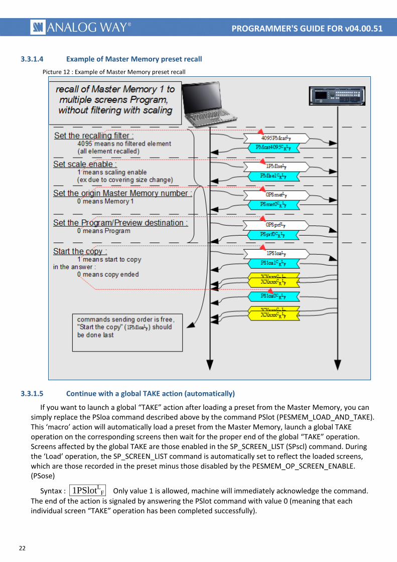
3.3.1.4 Example of Master Memory preset recall
Picture 12 : Example of Master Memory preset recall
3.3.1.5 Continue with a global TAKE action (automatically)
If you want to launch a global “TAKE” action after loading a preset from the Master Memory, you can simply replace the PSloa command described above by the command PSlot (PESMEM_LOAD_AND_TAKE). This ‘macro’ action will automatically load a preset from the Master Memory, launch a global TAKE operation on the corresponding screens then wait for the proper end of the global “TAKE” operation. Screens affected by the global TAKE are those enabled in the SP_SCREEN_LIST (SPscl) command. During the ‘Load’ operation, the SP_SCREEN_LIST command is automatically set to reflect the loaded screens, which are those recorded in the preset minus those disabled by the PESMEM_OP_SCREEN_ENABLE. (PSose)
Syntax : 1PSlotL
F Only value 1 is allowed, machine will immediately acknowledge the command.
The end of the action is signaled by answering the PSlot command with value 0 (meaning that each individual screen “TAKE” operation has been completed successfully).
23
PROGRAMMER'S GUIDE FOR v04.00.51
Important : Before using the PSlot command, you need to set parameters like memory number, destination screen, filters, options (see in §Detailed commands sequence section above for more information).
3.4 Changing the source displayed in a layer
3.4.1 Usage
Picture 13 : Changing layer source - Web RCS The “Layer Source change” action allows
changing the source displayed in a layer of a screen, on the Program or Preview output. Source type can be “live sources”, frames, logos or color.
3.4.2 LiveCore™ layers reminder
Pictures are displayed on a screen in overlapping layers. Each layer can contain a predefined picture of any type, “Frame”, live input or “Logo”, independently on the layer depth.
The first layer is the lowest, it can be covered by any upper layer.
3.4.3 Detailed commands sequence
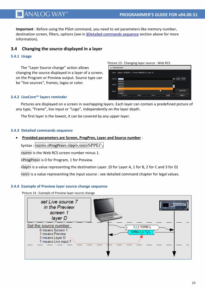
Provided parameters are Screen, ProgPrev, Layer and Source number :
Syntax : <scrn>,<ProgPrev>,<layr>,<src>SPPEiLF
<scrn> is the Web RCS screen number minus 1.
<ProgPrev> is 0 for Program, 1 for Preview.
<layr> is a value representing the destination Layer. (0 for Layer A, 1 for B, 2 for C and 3 for D)
<src> is a value representing the input source : see detailed command chapter for legal values.
3.4.4 Example of Preview layer source change sequence
Picture 14 : Example of Preview layer source change
24
PROGRAMMER'S GUIDE FOR v04.00.51
3.5 Changing a native background
3.5.1 Usage
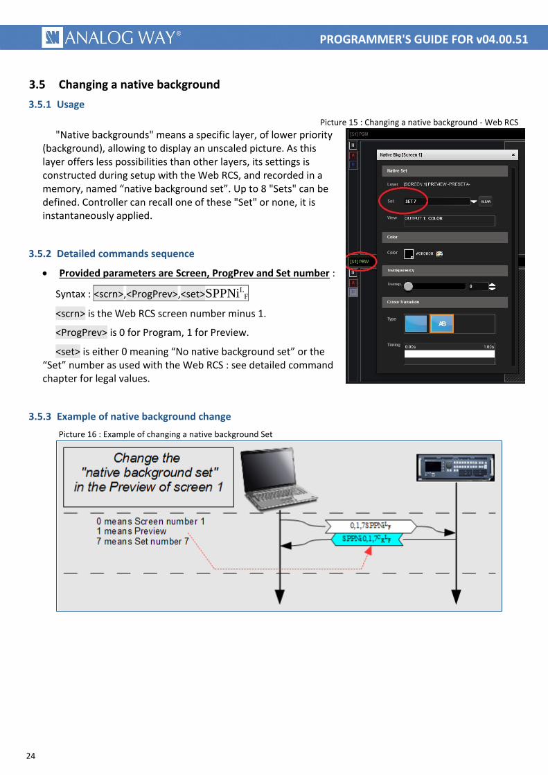
Picture 15 : Changing a native background - Web RCS
"Native backgrounds" means a specific layer, of lower priority (background), allowing to display an unscaled picture. As this layer offers less possibilities than other layers, its settings is constructed during setup with the Web RCS, and recorded in a memory, named “native background set”. Up to 8 "Sets" can be defined. Controller can recall one of these "Set" or none, it is instantaneously applied.
3.5.2 Detailed commands sequence
Provided parameters are Screen, ProgPrev and Set number :
Syntax : <scrn>,<ProgPrev>,<set>SPPNiLF
<scrn> is the Web RCS screen number minus 1.
<ProgPrev> is 0 for Program, 1 for Preview.
<set> is either 0 meaning “No native background set” or the “Set” number as used with the Web RCS : see detailed command chapter for legal values.
3.5.3 Example of native background change
Picture 16 : Example of changing a native background Set

25
PROGRAMMER'S GUIDE FOR v04.00.51
3.6 Single Screen TAKE : Transitioning the Preview content to the Program (single screen)
3.6.1 Usage
The single screen “TAKE” action allows transitioning, for a single screen, the “Preview” content (next state) to the “Program” (current state) using the current transition.
3.6.2 LiveCore™ transitions reminder
Picture modifications can be made directly on the program screen or can be prepared on the preview screen and applied synchronously through the TAKE command. The device will apply all preset changes in one step, using the user parameters.
3.6.3 Detailed commands sequence
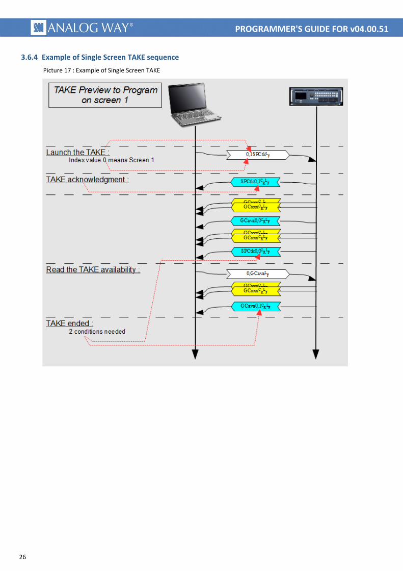
Launch the TAKE action : Launch the TAKE by writing the value 1.
Syntax : <scrn>,1SPCtkL
F <scrn> is the Web RCS screen number minus 1.
Only value 1 is allowed, machine will immediately acknowledge the command.
Wait until the end of operation : Operation is ended when register SP_TAKE value returns to 0 and when register GROUP_AVA value is 1.
In the following lines, <scrn> is the Web RCS screen number minus 1.
Answer 1 : SPCtk<scrn>,0C
RL
F wait until this answer is received.
Command 2 : <scrn>,GCavaL
F send this read command.
Answer 2 : GCava<scrn>,1C
RL
F and wait until this answer is received.
26
PROGRAMMER'S GUIDE FOR v04.00.51
3.6.4 Example of Single Screen TAKE sequence
Picture 17 : Example of Single Screen TAKE

27
PROGRAMMER'S GUIDE FOR v04.00.51
3.7 Global TAKE: Transitioning the Preview content to the Program (multiple screens)
3.7.1 Usage
The global “TAKE” action allows transitioning, for multiple screens, the “Preview” content (next state) to the “Program” (current state) using the current transitions.
3.7.2 Detailed commands sequence
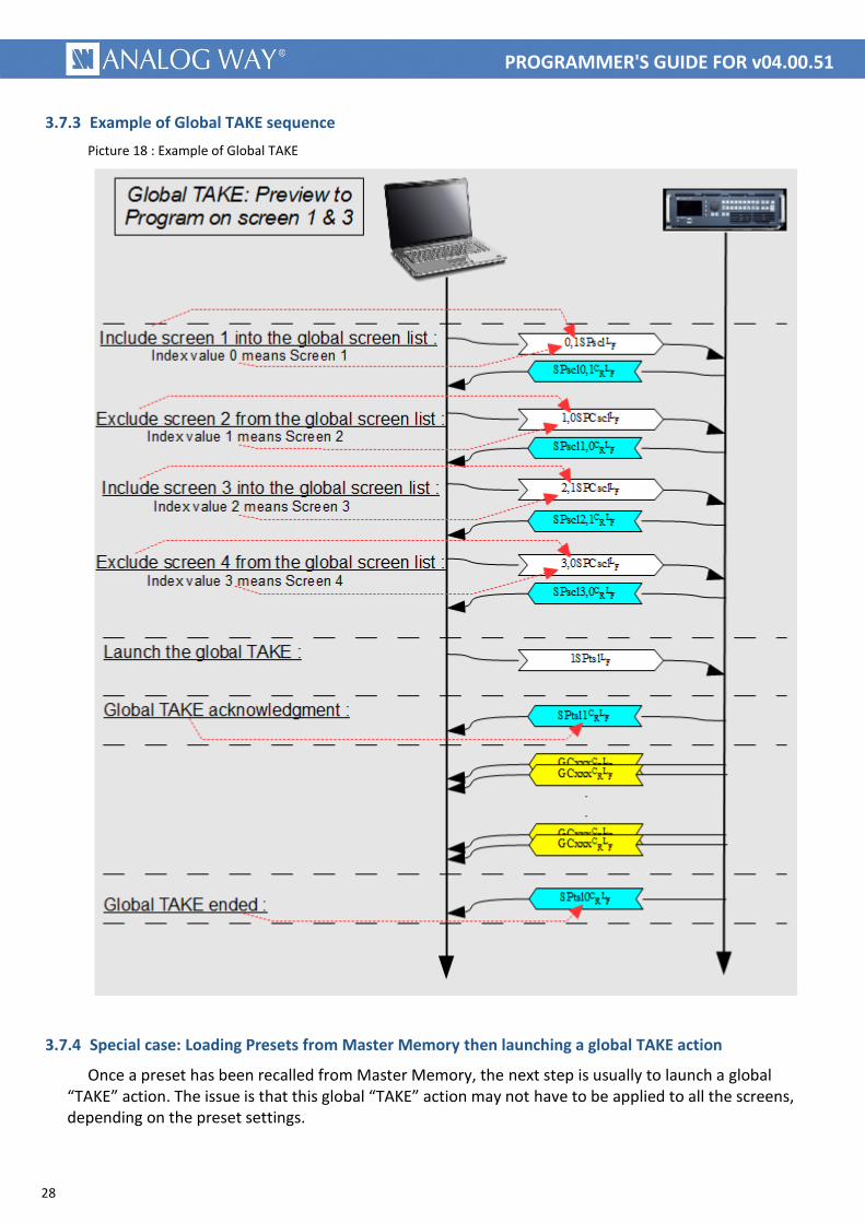
Define which screens will be affected by the global TAKE action : Include a screen in the global screen list by writing the value 1 or exclude a screen from the global screen list by writing the value 0. It should be repeated for each existing screen.
Syntax : <Screen>,<value>SPsclL
F
<Screen> is the destination screen to be included or excluded from future global “TAKE” actions.
<value> can be 0 to exclude that screen from future global “TAKE” actions or 1 to include it.
Launch the global TAKE action : Launch the global “TAKE” action by writing the value 1. This command uses the global screen list to determine which screens will be affected.
Syntax : <value>SPtslL
F Only value 1 is allowed, machine will immediately acknowledge the
command.
This command automatically waits until the end of operation : the global “TAKE” action is ended when register SPtsl (SP_TAKE_SCREEN_LIST) value returns to 0, i.e. when all the individual screen “TAKE” actions have been successfully completed.
Important : Launching a global “TAKE” does not change the global screen list content.
Important : The global screen list content is automatically modified during a PESMEM_LOAD_AND_TAKE (PSlot) if enabled by the SP_SET_SCREEN_LIST_ON_PESMEM_LOAD (SPslu) command.
28
PROGRAMMER'S GUIDE FOR v04.00.51
3.7.3 Example of Global TAKE sequence
Picture 18 : Example of Global TAKE
3.7.4 Special case: Loading Presets from Master Memory then launching a global TAKE action
Once a preset has been recalled from Master Memory, the next step is usually to launch a global “TAKE” action. The issue is that this global “TAKE” action may not have to be applied to all the screens, depending on the preset settings.

29
PROGRAMMER'S GUIDE FOR v04.00.51
This can be achieved manually by updating the global screen list as described above, but this requires knowing in advance the screens that should be excluded or not from this action. This can be also achieved automatically using the PSlot command (see section 3.3.1.5 for more information).
Another useful option is to enable the automatic filling of the global screen list using the SPslu command (SP_SET_SCREEN_LIST_ON_PESMEM_LOAD):
Syntax : <value>SPsluL
F
<value> can be 0 to disable the option or 1 to enable the option.
When this option is enabled, recalling a preset from Master Memory will also update automatically the global screen list (SPslu registers) according to the preset configuration. You can then use the SPtsl command to launch a global “TAKE” action and waits for the end of the process on the related screens.
30
PROGRAMMER'S GUIDE FOR v04.00.51
3.8 Configuring the Monitoring full screen mode
3.8.1 Usage
This command sequence sets the Monitoring output to full screen mode, sets the full screen mode source and updates/refreshes the Monitoring output.
3.8.2 Detailed commands sequence
Start the monitoring configuration change : Prepare the monitoring for a new configuration by writing the value 0.
Syntax : <dev>,0MLupdL
F
<dev> is the device index (0 for Master device, 1 for Slave device).
Enable monitoring full screen mode : Enable full screen mode by writing the value 1.
Syntax : <dev>,1MLfenL
F
<dev> is the device index (0 for Master device, 1 for Slave device).
Select source : Select the Monitoring source that will be displayed (full screen).
Syntax : <dev>,<src>MLfesL
F
<dev> is the device index (0 for Master device, 1 for Slave device).
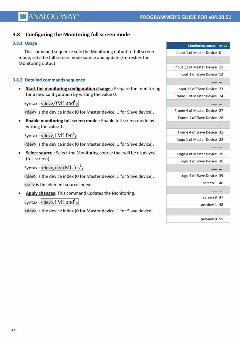
<src> is the element source index:
Apply changes: This command updates the Monitoring.
Syntax : <dev>,1MLupdL
F
<dev> is the device index (0 for Master device, 1 for Slave device).
Monitoring source value
Input 1 of Master Device 0
…… …
Input 12 of Master Device 11
Input 1 of Slave Device 12
…… …
Input 12 of Slave Device 23
Frame 1 of Master Device 24
…… …
Frame 4 of Master Device 27
Frame 1 of Slave Device 28
…… …
Frame 4 of Slave Device 31
Logo 1 of Master Device 32
…… …
Logo 4 of Master Device 35
Logo 1 of Slave Device 36
…… …
Logo 4 of Slave Device 39
screen 1 40
…… …
screen 8 47
preview 1 48
…… …
preview 8 55
31
PROGRAMMER'S GUIDE FOR v04.00.51
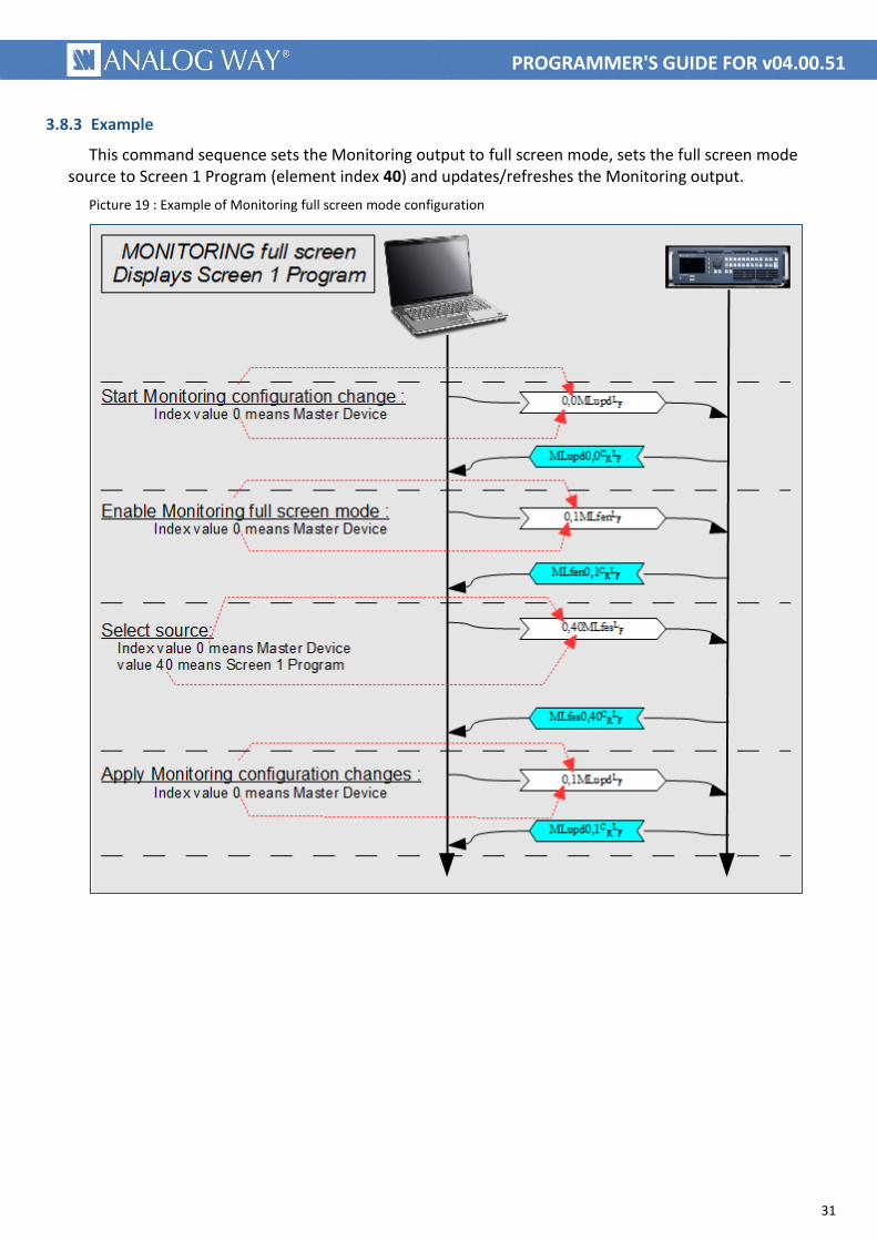
3.8.3 Example
This command sequence sets the Monitoring output to full screen mode, sets the full screen mode source to Screen 1 Program (element index 40) and updates/refreshes the Monitoring output.
Picture 19 : Example of Monitoring full screen mode configuration

32
PROGRAMMER'S GUIDE FOR v04.00.51
3.9 Configuring the Monitoring Mosaic mode
3.9.1 Usage
This command sequence sets the Monitoring output to Mosaic mode, sets one source in a Monitoring window and updates/refreshes the Monitoring output.
3.9.2 Detailed commands sequence
Start the monitoring configuration change : This command prepares the Monitoring for a new configuration by writing the value 0.
Syntax : <dev>,0MLupdL
F
<dev> is the device index (0 for Master device, 1 for Slave device).
Enable monitoring Mosaic mode : This command enables Mosaic mode by writing the value 0.
Syntax : <dev>,0MLfenL
F
<dev> is the device index (0 for Master device, 1 for Slave device).
Select source for one of the Windows: This command sets the source displayed in a Monitoring window.
Syntax : <dev>,<elt>,<src>MLcesL
F
<dev> is the device index (0 for Master device, 1 for Slave device)
<elt> is the Monitoring Mosaic window index (0 to 7 or 0 to 11 depending on your configuration)
<src> is the element source index (for possible values, see chapter 3.7)
Apply changes: This command updates the Monitoring.
Syntax : <dev>,1MLupdL
F
<dev> is the device index (0 for Master device, 1 for Slave device).
33
PROGRAMMER'S GUIDE FOR v04.00.51
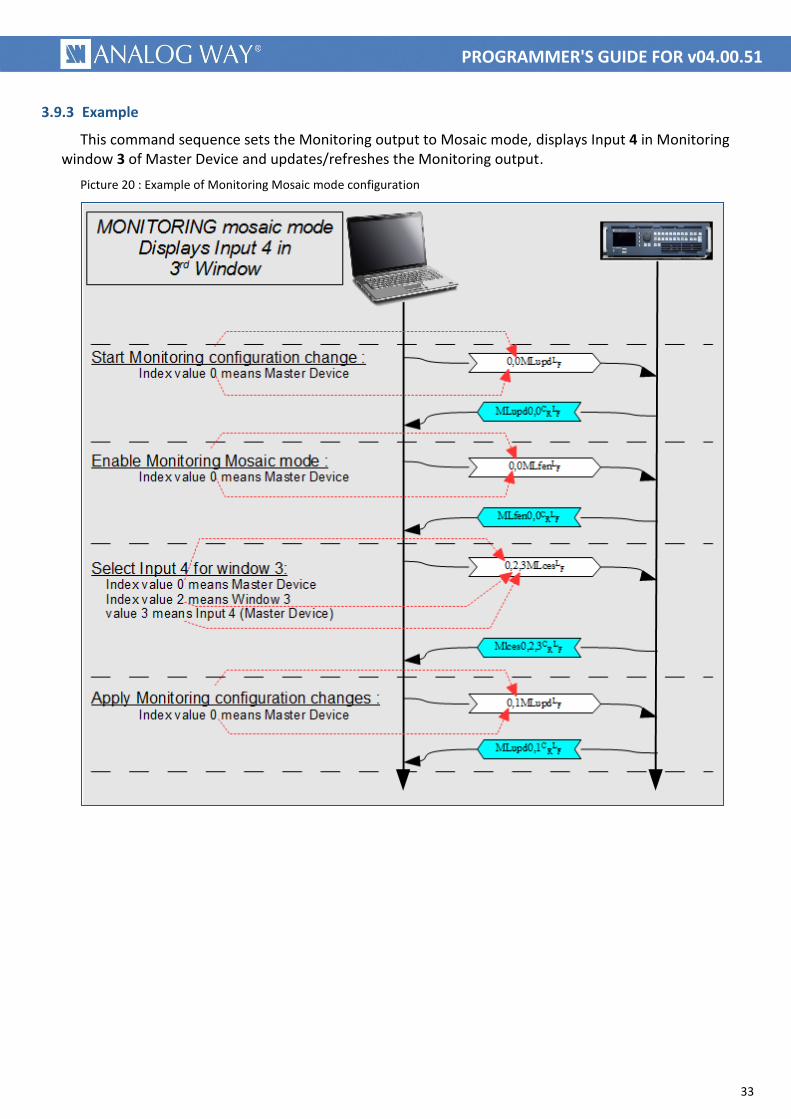
3.9.3 Example
This command sequence sets the Monitoring output to Mosaic mode, displays Input 4 in Monitoring window 3 of Master Device and updates/refreshes the Monitoring output.
Picture 20 : Example of Monitoring Mosaic mode configuration

34
PROGRAMMER'S GUIDE FOR v04.00.51
3.10 Selecting a Monitoring preset
3.10.1 Usage
This command sequence selects a Monitoring preset and updates/refreshes the Monitoring output.
3.10.2 Detailed commands sequence
Start the monitoring configuration change : This command prepares the Monitoring for a new configuration by writing the value 0.
Syntax : <dev>,0MLupdL
F
<dev> is the device index (0 for Master device, 1 for Slave device).
Load the monitoring preset : This command recalls a Monitoring Preset from Memory.
Syntax : <mem>,<dev>,1MMloaL
F
<mem> is the Monitoring preset memory index (0 to 7).
<dev> is the device index (0 for Master device, 1 for Slave device).
Apply changes: This command updates the Monitoring.
Syntax : <dev>,1MLupdL
F <dev> is the device index (0 for Master device, 1 for Slave device).
3.10.3 Example
This command recalls Monitoring Preset 3 from memory and updates/refreshes the Monitoring output.
Picture 21 : Example of Monitoring preset recall
35
PROGRAMMER'S GUIDE FOR v04.00.51
3.11 Loading a “Confidence monitor” preset from memory
3.11.1 Usage
This command allows to load a previously memorized preset.
3.11.2 Detailed commands sequence
Load a confidence monitor preset :
Syntax : <mem>,<screen>,1CLloaL
F
<mem> is the memory index (16 memories addressed from 0 to 15).
<screen> is the destination screen index (8 screens addressed from 0 to 7).
3.12 Using snapshots
Small snapshots of live inputs, frame and logos are available. Live input snapshots are regularly refreshed, while frame and logos snapshots are refreshed only on change.
Snapshot request rate must not be more than 1 per second.
Picture size is 128 pixels (width) by up to 128 pixels (height). Black borders are automatically added, depending on aspect ratio.
Picture type is PNG, despite the suffix BMP.
Live inputs snapshot URL are:
http://<machine_ip>/assets/Snapshots/capture_in_1.bmp
up to
http://<machine_ip>/assets/Snapshots/capture_in_24.bmp
The number is depending on machine type and configuration.
Frames snapshot URL are :
http://<machine ip>/assets/Stills/Thumbnails/capture_fr_1.bmp
up to
http://<machine ip>/assets/Stills/Thumbnails/capture_fr_4.bmp
Logos snapshot URL are :
http://<machine ip>/assets/Stills/Thumbnails/capture_lg_1.bmp
up to
http://<machine ip>/assets/Stills/Thumbnails/capture_lg_4.bmp

36
PROGRAMMER'S GUIDE FOR v04.00.51
3.13 Shutting down or rebooting the LiveCore™ device
3.13.1 Usage
This command sequence reboots or shuts down the device (with or without the Wake on LAN feature enabled).
3.13.2 Detailed commands sequence
Reboot the device : This command restarts the device by writing the value 1.
Syntax : <dev>,1PCrebL
F
<dev> is the device index (0 for Master device, 1 for Slave device).
OR
Power off the device : This command shuts down and powers off the device by writing the value 1 (manual restart required).
Syntax : <dev>,1PCshtL
F
<dev> is the device index (0 for Master device, 1 for Slave device).
OR
Shutdown the device (with Wake on LAN feature enabled): This command shuts down the device and enables the Wake on LAN feature by writing the value 2 (see next chapter for more information).
Syntax : <dev>,2PCshtL
F
<dev> is the device index (0 for Master device, 1 for Slave device).
3.14 Waking the LiveCore™ device (over LAN)
3.14.1 Description
When the device has been shut down with the Wake on LAN feature enabled (‘sleep’ state), the only way to wake this device is to send a broadcast message over the network (‘magic packet’).
3.14.2 Wake on LAN and Magic Packet
Wake on LAN (or WOL) is the ability to send a signal over a local area network (LAN) to wake up a device. When the device is powered off with the Wake-On-LAN feature enabled, no operating system is running and there is no IP address assigned. Luckily, the MAC (Media Access Control) address being hardcoded in the network adaptor remains usable to identify a device in all states.
Using this MAC address, another system on the network may send to the sleeping device a wake-up signal. The wake up signal is a specific data frame, called ‘magic packet’, containing the MAC address of the remote network card. The magic packet is sent to all devices on the network (UDP broadcast) but is caught only by the device owning the matching MAC Address.
37
PROGRAMMER'S GUIDE FOR v04.00.51
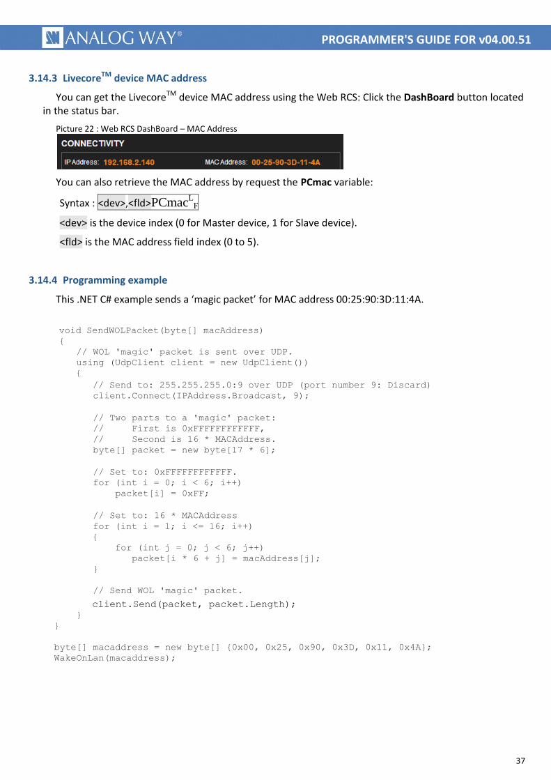
3.14.3 LivecoreTM device MAC address
You can get the LivecoreTM device MAC address using the Web RCS: Click the DashBoard button located in the status bar.
Picture 22 : Web RCS DashBoard – MAC Address
You can also retrieve the MAC address by request the PCmac variable:
Syntax : <dev>,<fld>PCmacL
F
<dev> is the device index (0 for Master device, 1 for Slave device).
<fld> is the MAC address field index (0 to 5).
3.14.4 Programming example
This .NET C# example sends a ‘magic packet’ for MAC address 00:25:90:3D:11:4A.
void SendWOLPacket(byte[] macAddress) {
// WOL 'magic' packet is sent over UDP. using (UdpClient client = new UdpClient())
{ // Send to: 255.255.255.0:9 over UDP (port number 9: Discard) client.Connect(IPAddress.Broadcast, 9); // Two parts to a 'magic' packet: // First is 0xFFFFFFFFFFFF, // Second is 16 * MACAddress. byte[] packet = new byte[17 * 6]; // Set to: 0xFFFFFFFFFFFF. for (int i = 0; i < 6; i++) packet[i] = 0xFF; // Set to: 16 * MACAddress for (int i = 1; i <= 16; i++) { for (int j = 0; j < 6; j++) packet[i * 6 + j] = macAddress[j]; }
// Send WOL 'magic' packet.
client.Send(packet, packet.Length);
} }
byte[] macaddress = new byte[] {0x00, 0x25, 0x90, 0x3D, 0x11, 0x4A};
WakeOnLan(macaddress);
38
PROGRAMMER'S GUIDE FOR v04.00.51
3.15 GPI General Purpose Input
3.15.1 Usage
This command sequence reads the GPI availability flag, sets the GPI mode and reads the GPI status.
3.15.2 Detailed commands sequence
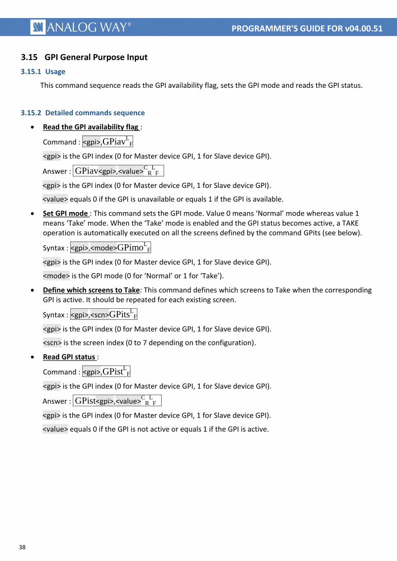
Read the GPI availability flag :
Command : <gpi>,GPiavL
F
<gpi> is the GPI index (0 for Master device GPI, 1 for Slave device GPI).
Answer : GPiav<gpi>,<value>C
RL
F
<gpi> is the GPI index (0 for Master device GPI, 1 for Slave device GPI).
<value> equals 0 if the GPI is unavailable or equals 1 if the GPI is available.
Set GPI mode : This command sets the GPI mode. Value 0 means ‘Normal’ mode whereas value 1 means ‘Take’ mode. When the ‘Take’ mode is enabled and the GPI status becomes active, a TAKE operation is automatically executed on all the screens defined by the command GPits (see below).
Syntax : <gpi>,<mode>GPimoL
F
<gpi> is the GPI index (0 for Master device GPI, 1 for Slave device GPI).
<mode> is the GPI mode (0 for ‘Normal’ or 1 for ‘Take’).
Define which screens to Take: This command defines which screens to Take when the corresponding GPI is active. It should be repeated for each existing screen.
Syntax : <gpi>,<scn>GPitsL
F
<gpi> is the GPI index (0 for Master device GPI, 1 for Slave device GPI).
<scn> is the screen index (0 to 7 depending on the configuration).
Read GPI status :
Command : <gpi>,GPistL
F
<gpi> is the GPI index (0 for Master device GPI, 1 for Slave device GPI).
Answer : GPist<gpi>,<value>C
RL
F
<gpi> is the GPI index (0 for Master device GPI, 1 for Slave device GPI).
<value> equals 0 if the GPI is not active or equals 1 if the GPI is active.
39
PROGRAMMER'S GUIDE FOR v04.00.51
3.15.3 Example
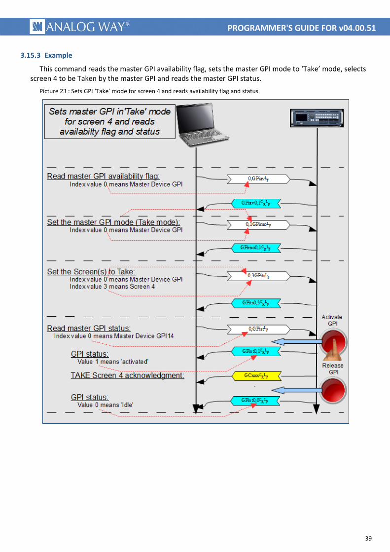
This command reads the master GPI availability flag, sets the master GPI mode to ‘Take’ mode, selects screen 4 to be Taken by the master GPI and reads the master GPI status.
Picture 23 : Sets GPI ‘Take’ mode for screen 4 and reads availability flag and status
40
PROGRAMMER'S GUIDE FOR v04.00.51
3.16 GPO General Purpose Output (Free mode)
3.16.1 Usage
This command sequence reads the GPO availability flag, sets the GPO mode and activates the GPO output.
3.16.2 Detailed commands sequence
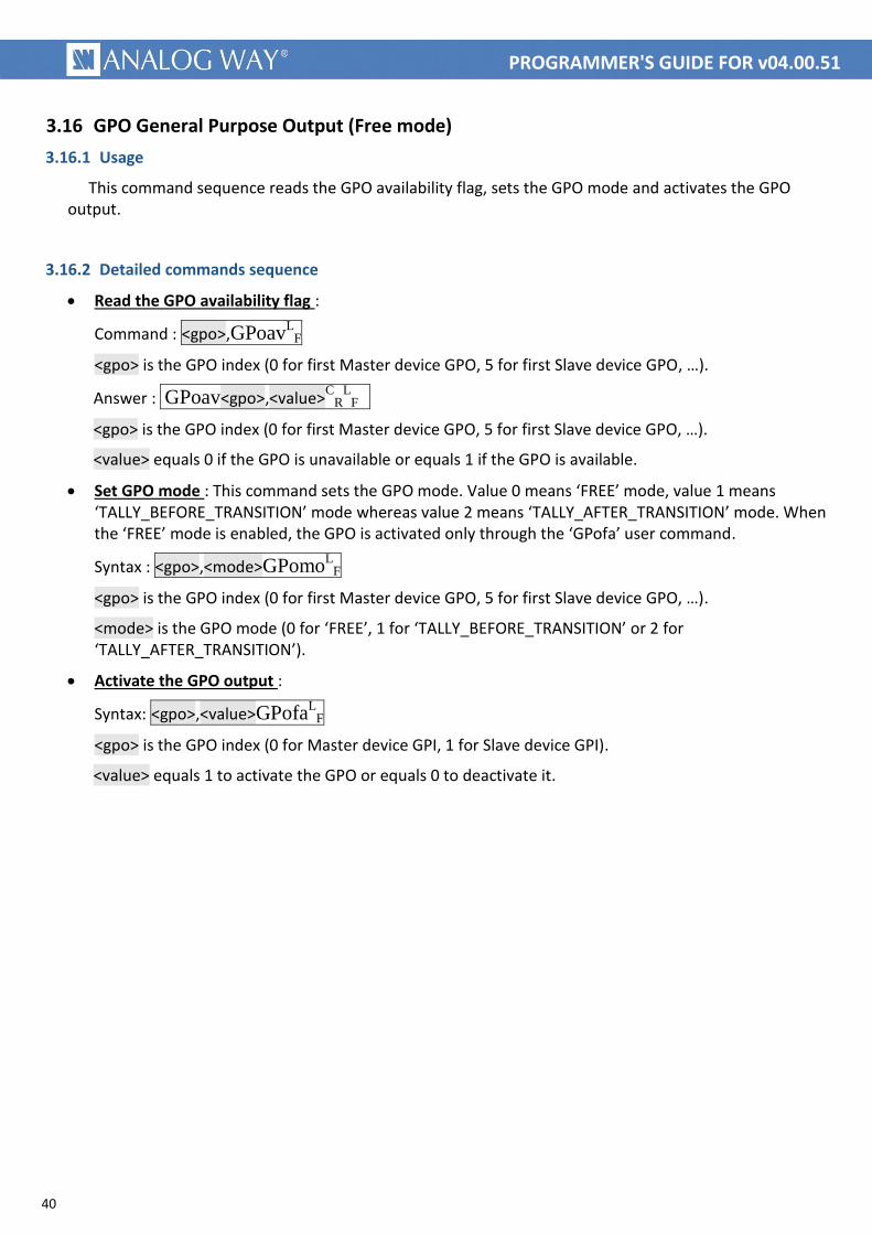
Read the GPO availability flag :
Command : <gpo>,GPoavL
F
<gpo> is the GPO index (0 for first Master device GPO, 5 for first Slave device GPO, …).
Answer : GPoav<gpo>,<value>C
RL
F
<gpo> is the GPO index (0 for first Master device GPO, 5 for first Slave device GPO, …).
<value> equals 0 if the GPO is unavailable or equals 1 if the GPO is available.
Set GPO mode : This command sets the GPO mode. Value 0 means ‘FREE’ mode, value 1 means ‘TALLY_BEFORE_TRANSITION’ mode whereas value 2 means ‘TALLY_AFTER_TRANSITION’ mode. When the ‘FREE’ mode is enabled, the GPO is activated only through the ‘GPofa’ user command.
Syntax : <gpo>,<mode>GPomoL
F
<gpo> is the GPO index (0 for first Master device GPO, 5 for first Slave device GPO, …).
<mode> is the GPO mode (0 for ‘FREE’, 1 for ‘TALLY_BEFORE_TRANSITION’ or 2 for ‘TALLY_AFTER_TRANSITION’).
Activate the GPO output :
Syntax: <gpo>,<value>GPofaL
F
<gpo> is the GPO index (0 for Master device GPI, 1 for Slave device GPI).
<value> equals 1 to activate the GPO or equals 0 to deactivate it.
41
PROGRAMMER'S GUIDE FOR v04.00.51
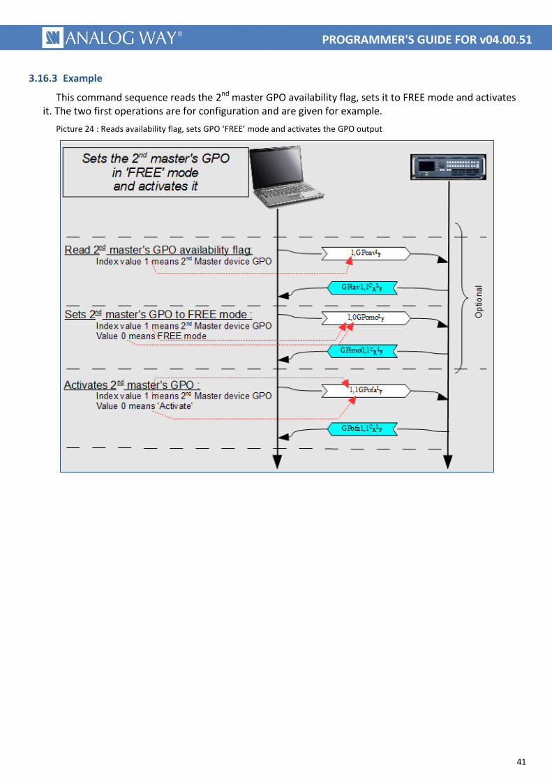
3.16.3 Example
This command sequence reads the 2nd master GPO availability flag, sets it to FREE mode and activates it. The two first operations are for configuration and are given for example.
Picture 24 : Reads availability flag, sets GPO ‘FREE’ mode and activates the GPO output
42
PROGRAMMER'S GUIDE FOR v04.00.51
3.17 TALLY status
3.17.1 Usage
These commands allow to get notified as soon as an input / frame / logo is displayed either on a program or preview screen. The same commands may be used to be notified (push) or to query an input status (polling).
3.17.2 Detailed commands sequence
Read the status of an Input / frame / logo displayed on a Program sceen :
Command : <input>,TAoprL
F
<input> is the input / logo / frame index. (please look at ENUM_INPUTLAYER in LiveCore_TPP_variables_for_v04-00-51.pdf document or earlier)
Answer : TAopr<input>,<value>C
RL
F
<input> is the input / logo / frame index. (please look at ENUM_INPUTLAYER in LiveCore_TPP_variables_for_v04-00-51.pdf document or earlier)
<value> equals 0 if the input / logo / frame is not displayed on a Program screen.
Read the status of an Input / frame / logo displayed on a Preview sceen :
Command : <input>,TAopwL
F
<input> is the input / logo / frame index. (please look at ENUM_INPUTLAYER in LiveCore_TPP_variables_for_v04-00-51.pdf document or earlier)
Answer : TAopw<input>,<value>C
RL
F
<input> is the input / logo / frame index. (please look at ENUM_INPUTLAYER in LiveCore_TPP_variables_for_v04-00-51.pdf document or earlier)
<value> equals 0 if the input / logo / frame is not displayed on a Preview screen.
43
PROGRAMMER'S GUIDE FOR v04.00.51
4 NOTES
4.1 Using this document
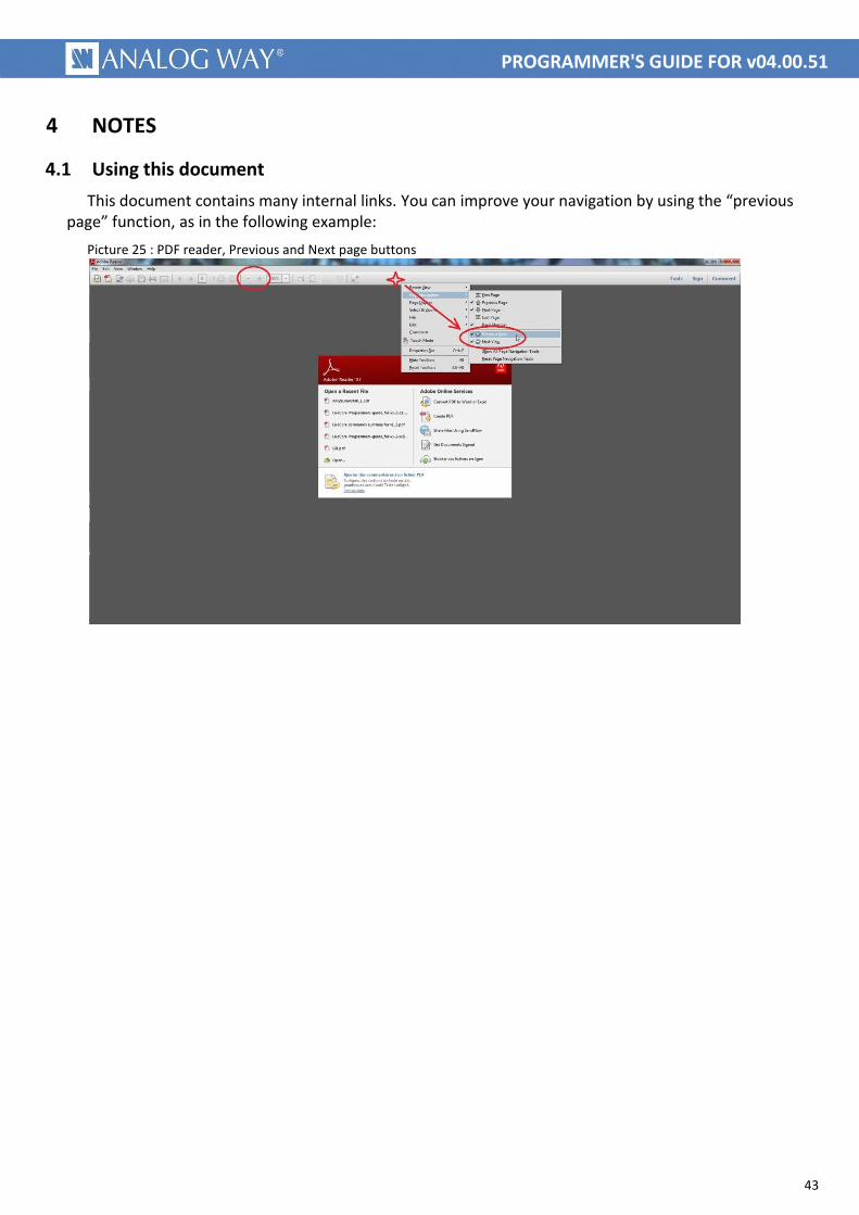
This document contains many internal links. You can improve your navigation by using the “previous page” function, as in the following example:
Picture 25 : PDF reader, Previous and Next page buttons

44
PROGRAMMER'S GUIDE FOR v04.00.51

45
PROGRAMMER'S GUIDE FOR v04.00.51
V1.00 – Apr/04/2016