Embed Size (px)
Citation preview

Product Data SheetMarch 2015
00813-0300-4750, Rev AA
Rosemount 8750W Magnetic Flowmeter Systemfor Utility, Water, and Wastewater Applications
Best in class value with performance, reliability, and diagnostics suited for monitoring applications
Reliable all welded coil housing and lightweight sensor design rated to IP68
Process Diagnostics and Smart Meter Verification to provide better insight into the process and the meter's health
Available with drinking water certifications

Rosemount 8750W Flowmeter Platform March 2015
Product Selection GuideThe Rosemount 8750W Magnetic Flowmeter Platform is available in flanged and wafer styles, as well as remote and integral transmitter configurations to ensure compatibility with utility, water, and wastewater applications.
For transmitter details see Table 1 and Table 9.
For sensor styles and details see Table 2 and Table 10.
For available lining materials see Table 11.
For available electrode materials and electrode types see Table 12.
For process reference (grounding) options see Table 13 and Table 14.
For guidance on selecting materials, refer to the Magnetic Flowmeter Material Selection Guide located on Rosemount.com (Technical Data Sheet Number 00816-0100-3033). For more information regarding the available product offering see the ordering information, Table 6 through Table 12.
Table 1. Transmitter Selections
Table 2. Sensor Selection
Contents
Magmeter Diagnostics . . . . . . . . . . . . . . . . . . . . . . . . . . . . . . . 3
Magnetic Flowmeter Sizing . . . . . . . . . . . . . . . . . . . . . . . . . . . . 4
Ordering Information . . . . . . . . . . . . . . . . . . . . . . . . . . . . . . . . 6
Product Specifications . . . . . . . . . . . . . . . . . . . . . . . . . . . . . . . 13
Rosemount 8750W Field Mount Transmitter Specifications . . 15
Rosemount 8750W Wall Mount Transmitter Specifications . .19
Rosemount 8750W Flanged Sensor Specifications . . . . . . . . .23
Rosemount 8750W Wafer Sensor Specifications . . . . . . . . . . .26
Product Certifications . . . . . . . . . . . . . . . . . . . . . . . . . . . . . . .28
Dimensional Drawings . . . . . . . . . . . . . . . . . . . . . . . . . . . . . . .33
Transmitter General characteristics
Field Mount• Integral and remote mount configurations
available
• HART®/Analog and Pulse outputs available
• Advanced Diagnostics available
• Optical switch local operator interface (optional)
• Two discrete channels (optional)
Wall Mount • Remote mount configuration
• HART/Analog and Pulse outputs available
• Advanced Diagnostics available
• Easy to use local operator interface with dedicated configuration buttons (optional)
Sensor General characteristics
Flanged • Flanged process connections
• Welded coil housing
• 1/2-in. (15mm) to 48-in. (1200mm)
• Standard, reference, and bullet-nose electrodes available
Wafer • Wafer (flangeless) design
• Welded coil housing
• 11/2-in. (40mm) to 8-in. (200mm)
• Standard, reference, and bullet-nose electrodes available
2 www.rosemount.com

Rosemount 8750W Flowmeter PlatformMarch 2015
Magmeter Diagnostics
Rosemount diagnostics reduce cost & improve output by enabling new practices Rosemount Magnetic Flowmeters provide device diagnostics that detect and warn of abnormal situations throughout the life of the meter - from installation to maintenance and meter verification. With Rosemount Magnetic Flowmeter diagnostics enabled, plant availability and throughput can be improved, and costs through simplified installation, maintenance and troubleshooting can be reduced.
Options for accessing diagnostics
Rosemount Magmeter Diagnostics can be accessed through the Local Operator Interface (LOI), a Field Communicator, AMS® Suite: Intelligent Device Manager, and ProLink®. Contact your local Emerson Process Management representative to activate diagnostics or for diagnostic availability on existing transmitters.
Access diagnostics through the LOI for quicker installation, maintenance, and meter verification
Rosemount Magnetic Flowmeter Diagnostics are available through the LOI to simplify maintenance.
Access diagnostics through ProLink III v. 3.0
Simplify maintenance and troubleshooting practices by utilizing ProLink III v3.0 to access diagnostics and troubleshooting information, log variable data, run SMART Meter Verification, and print verification reports.
Access diagnostics through AMS Intelligent Device Manager for the ultimate value
The value of the diagnostics increases significantly when AMS Intelligent Device Manager is used. AMS Intelligent Device Manager provides a simplified screen flow and procedures for how to respond to the diagnostic messages.
Diagnostic name Diagnostic category Product capability
Basic Diagnostics
Tunable Empty Pipe Process Standard
Electronics Temperature Maintenance Standard
Coil Fault Maintenance Standard
Transmitter Fault Maintenance Standard
Reverse Flow Process Standard
Coil Current(1) Maintenance Standard
Electrode Saturation(1) Process/Maintenance Standard
Advanced Diagnostics
High Process Noise Process Suite 1 (DA1)
Grounding and Wiring Fault Installation Suite 1 (DA1)
Coated Electrode Detection(1)
(1) Only available with field mount transmitter.
Process Suite 1 (DA1)
Commanded SMART™ Meter Verification Meter Health Suite 2 (DA2)
Continuous SMART Meter Verification(1) Meter Health Suite 2 (DA2)
4-20 mA1 Loop Verification Installation Suite 2 (DA2)
3www.rosemount.com
Rosemount 8750W Flowmeter Platform March 2015
4 www.rosemount.com
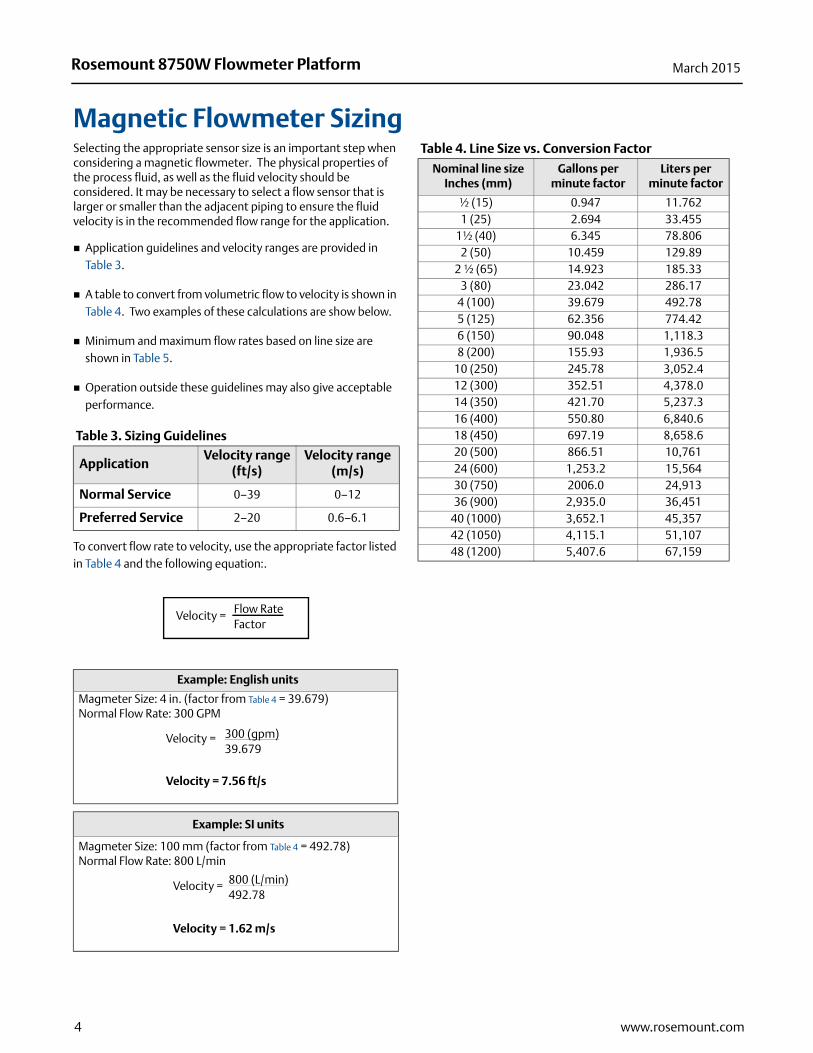
Magnetic Flowmeter SizingSelecting the appropriate sensor size is an important step when considering a magnetic flowmeter. The physical properties of the process fluid, as well as the fluid velocity should be considered. It may be necessary to select a flow sensor that is larger or smaller than the adjacent piping to ensure the fluid velocity is in the recommended flow range for the application.
Application guidelines and velocity ranges are provided in Table 3.
A table to convert from volumetric flow to velocity is shown in Table 4. Two examples of these calculations are show below.
Minimum and maximum flow rates based on line size are shown in Table 5.
Operation outside these guidelines may also give acceptable performance.
Table 3. Sizing Guidelines
To convert flow rate to velocity, use the appropriate factor listed in Table 4 and the following equation:.
Table 4. Line Size vs. Conversion Factor
ApplicationVelocity range
(ft/s)Velocity range
(m/s)
Normal Service 0–39 0–12
Preferred Service 2–20 0.6–6.1
Example: English units
Magmeter Size: 4 in. (factor from Table 4 = 39.679)Normal Flow Rate: 300 GPM
Example: SI units
Magmeter Size: 100 mm (factor from Table 4 = 492.78)Normal Flow Rate: 800 L/min
Velocity = Flow RateFactor
Velocity =
Velocity = 7.56 ft/s
300 (gpm)39.679
Velocity =
Velocity = 1.62 m/s
800 (L/min)492.78
Nominal line sizeInches (mm)
Gallons per minute factor
Liters per minute factor
½ (15) 0.947 11.7621 (25) 2.694 33.455
1½ (40) 6.345 78.8062 (50) 10.459 129.89
2 ½ (65) 14.923 185.333 (80) 23.042 286.17
4 (100) 39.679 492.785 (125) 62.356 774.426 (150) 90.048 1,118.38 (200) 155.93 1,936.5
10 (250) 245.78 3,052.412 (300) 352.51 4,378.014 (350) 421.70 5,237.316 (400) 550.80 6,840.618 (450) 697.19 8,658.620 (500) 866.51 10,76124 (600) 1,253.2 15,56430 (750) 2006.0 24,91336 (900) 2,935.0 36,451
40 (1000) 3,652.1 45,35742 (1050) 4,115.1 51,10748 (1200) 5,407.6 67,159
Rosemount 8750W Flowmeter PlatformMarch 2015
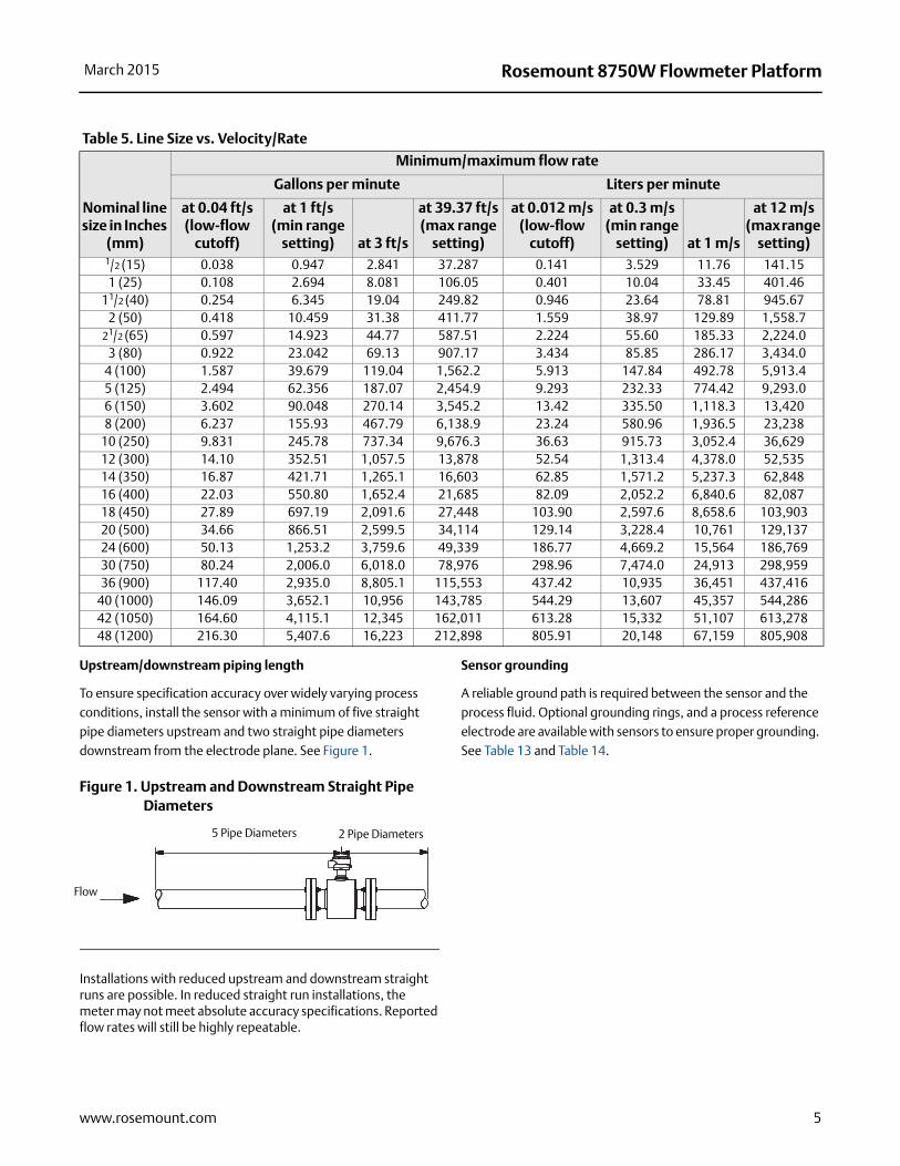
Upstream/downstream piping length
To ensure specification accuracy over widely varying process conditions, install the sensor with a minimum of five straight pipe diameters upstream and two straight pipe diameters downstream from the electrode plane. See Figure 1.
Figure 1. Upstream and Downstream Straight Pipe Diameters
Installations with reduced upstream and downstream straight runs are possible. In reduced straight run installations, the meter may not meet absolute accuracy specifications. Reported flow rates will still be highly repeatable.
Sensor grounding
A reliable ground path is required between the sensor and the process fluid. Optional grounding rings, and a process reference electrode are available with sensors to ensure proper grounding. See Table 13 and Table 14.
Table 5. Line Size vs. Velocity/Rate
Nominal line size in Inches
(mm)
Minimum/maximum flow rate
Gallons per minute Liters per minute
at 0.04 ft/s(low-flow
cutoff)
at 1 ft/s(min range
setting) at 3 ft/s
at 39.37 ft/s(max range
setting)
at 0.012 m/s(low-flow
cutoff)
at 0.3 m/s(min range
setting) at 1 m/s
at 12 m/s(max range
setting)1/2 (15) 0.038 0.947 2.841 37.287 0.141 3.529 11.76 141.151 (25) 0.108 2.694 8.081 106.05 0.401 10.04 33.45 401.46
11/2 (40) 0.254 6.345 19.04 249.82 0.946 23.64 78.81 945.672 (50) 0.418 10.459 31.38 411.77 1.559 38.97 129.89 1,558.7
21/2 (65) 0.597 14.923 44.77 587.51 2.224 55.60 185.33 2,224.03 (80) 0.922 23.042 69.13 907.17 3.434 85.85 286.17 3,434.0
4 (100) 1.587 39.679 119.04 1,562.2 5.913 147.84 492.78 5,913.45 (125) 2.494 62.356 187.07 2,454.9 9.293 232.33 774.42 9,293.06 (150) 3.602 90.048 270.14 3,545.2 13.42 335.50 1,118.3 13,4208 (200) 6.237 155.93 467.79 6,138.9 23.24 580.96 1,936.5 23,238
10 (250) 9.831 245.78 737.34 9,676.3 36.63 915.73 3,052.4 36,62912 (300) 14.10 352.51 1,057.5 13,878 52.54 1,313.4 4,378.0 52,53514 (350) 16.87 421.71 1,265.1 16,603 62.85 1,571.2 5,237.3 62,84816 (400) 22.03 550.80 1,652.4 21,685 82.09 2,052.2 6,840.6 82,08718 (450) 27.89 697.19 2,091.6 27,448 103.90 2,597.6 8,658.6 103,90320 (500) 34.66 866.51 2,599.5 34,114 129.14 3,228.4 10,761 129,13724 (600) 50.13 1,253.2 3,759.6 49,339 186.77 4,669.2 15,564 186,76930 (750) 80.24 2,006.0 6,018.0 78,976 298.96 7,474.0 24,913 298,95936 (900) 117.40 2,935.0 8,805.1 115,553 437.42 10,935 36,451 437,416
40 (1000) 146.09 3,652.1 10,956 143,785 544.29 13,607 45,357 544,28642 (1050) 164.60 4,115.1 12,345 162,011 613.28 15,332 51,107 613,27848 (1200) 216.30 5,407.6 16,223 212,898 805.91 20,148 67,159 805,908
Flow
5 Pipe Diameters 2 Pipe Diameters
5www.rosemount.com
Rosemount 8750W Flowmeter Platform March 2015
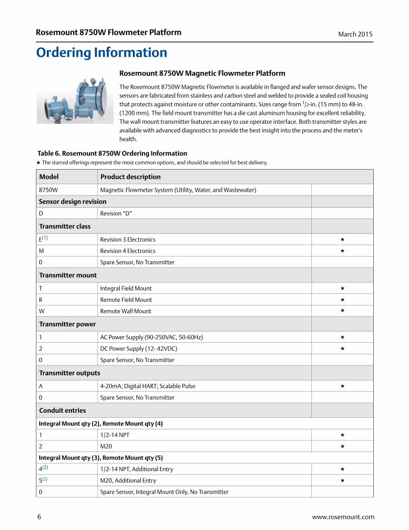
Ordering InformationRosemount 8750W Magnetic Flowmeter Platform
The Rosemount 8750W Magnetic Flowmeter is available in flanged and wafer sensor designs. The sensors are fabricated from stainless and carbon steel and welded to provide a sealed coil housing that protects against moisture or other contaminants. Sizes range from 1/2-in. (15 mm) to 48-in. (1200 mm). The field mount transmitter has a die cast aluminum housing for excellent reliability. The wall mount transmitter features an easy to use operator interface. Both transmitter styles are available with advanced diagnostics to provide the best insight into the process and the meter's health.
Table 6. Rosemount 8750W Ordering InformationH The starred offerings represent the most common options, and should be selected for best delivery.
Model Product description
8750W Magnetic Flowmeter System (Utility, Water, and Wastewater)
Sensor design revision
D Revision “D”
Transmitter class
E(1) Revision 3 Electronics H
M Revision 4 Electronics H
0 Spare Sensor, No Transmitter
Transmitter mount
T Integral Field Mount H
R Remote Field Mount H
W Remote Wall Mount H
Transmitter power
1 AC Power Supply (90-250VAC, 50-60Hz) H
2 DC Power Supply (12- 42VDC) H
0 Spare Sensor, No Transmitter
Transmitter outputs
A 4-20mA; Digital HART; Scalable Pulse H
0 Spare Sensor, No Transmitter
Conduit entries
Integral Mount qty (2), Remote Mount qty (4)
1 1/2-14 NPT H
2 M20 H
Integral Mount qty (3), Remote Mount qty (5)
4(2) 1/2-14 NPT, Additional Entry H
5(2) M20, Additional Entry H
0 Spare Sensor, Integral Mount Only, No Transmitter
6 www.rosemount.com
Rosemount 8750W Flowmeter PlatformMarch 2015
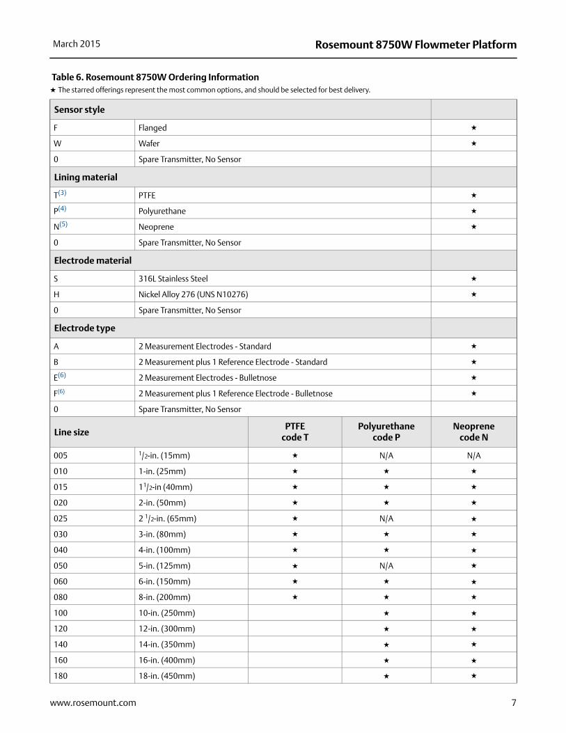
Sensor style
F Flanged H
W Wafer H
0 Spare Transmitter, No Sensor
Lining material
T(3) PTFE H
P(4) Polyurethane H
N(5) Neoprene H
0 Spare Transmitter, No Sensor
Electrode material
S 316L Stainless Steel H
H Nickel Alloy 276 (UNS N10276) H
0 Spare Transmitter, No Sensor
Electrode type
A 2 Measurement Electrodes - Standard H
B 2 Measurement plus 1 Reference Electrode - Standard H
E(6) 2 Measurement Electrodes - Bulletnose H
F(6) 2 Measurement plus 1 Reference Electrode - Bulletnose H
0 Spare Transmitter, No Sensor
Line sizePTFE
code TPolyurethane
code P Neoprene
code N
005 1/2-in. (15mm) H N/A N/A
010 1-in. (25mm) H H H
015 11/2-in (40mm) H H H
020 2-in. (50mm) H H H
025 2 1/2-in. (65mm) H N/A H
030 3-in. (80mm) H H H
040 4-in. (100mm) H H H
050 5-in. (125mm) H N/A H
060 6-in. (150mm) H H H
080 8-in. (200mm) H H H
100 10-in. (250mm) H H
120 12-in. (300mm) H H
140 14-in. (350mm) H H
160 16-in. (400mm) H H
180 18-in. (450mm) H H
Table 6. Rosemount 8750W Ordering InformationH The starred offerings represent the most common options, and should be selected for best delivery.
7www.rosemount.com

Rosemount 8750W Flowmeter Platform March 2015
200 20-in. (500mm) H H
240 24-in. (600mm) H H
300 30-in. (750mm) H H
360 36-in. (900mm) H H
400 40-in. (1000mm) N/A N/A
420 42-in. (1050mm) N/A
480 48-in. (1200mm) N/A
000 Spare Transmitter, No Sensor N/A N/A N/A
Flange type and material(7)
C Slip-On, Raised-Face, Carbon Steel H
S Slip-On, Raised-Face, 304/304L SST H
F Slip-On, Flat-Face, Carbon Steel
G Slip-On, Flat-Face, 304/304L SST
0 Spare Transmitter, No Sensor
Flange rating(7)
A1 ASME B16.5, Class 150
Refer to Table 7 for flange availability.
A3 ASME B16.5, Class 300
AB AWWA C207 Class B (Line Size 30" and above)
AD AWWA C207 Class D (Line Size 30" and above)
AE AWWA C207 Class E (Line Size 30" and above)
DC EN1092-1, PN6
DD EN1092-1, PN10
DE EN1092-1, PN16
DF EN 1092-1, PN25
DH EN 1092-1, PN40
GD GB/T9119, PN10
GE GB/T9119, PN16
GH GB/T9119, PN40
JP JIS B2220, 10K
JR JIS B2220, 20K
KU AS4087, PN16
KW AS4087, PN21
KY AS4087, PN35
TK AS2129, Table D
TL AS2129, Table E
00 Spare Transmitter, No Sensor
Table 6. Rosemount 8750W Ordering InformationH The starred offerings represent the most common options, and should be selected for best delivery.
8 www.rosemount.com
Rosemount 8750W Flowmeter PlatformMarch 2015
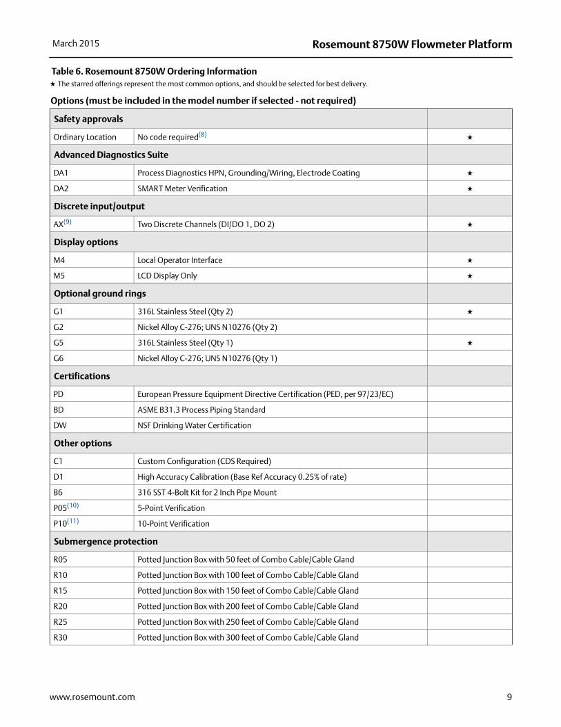
Options (must be included in the model number if selected - not required)
Safety approvals
Ordinary Location No code required(8) H
Advanced Diagnostics Suite
DA1 Process Diagnostics HPN, Grounding/Wiring, Electrode Coating H
DA2 SMART Meter Verification H
Discrete input/output
AX(9) Two Discrete Channels (DI/DO 1, DO 2) H
Display options
M4 Local Operator Interface H
M5 LCD Display Only H
Optional ground rings
G1 316L Stainless Steel (Qty 2) H
G2 Nickel Alloy C-276; UNS N10276 (Qty 2)
G5 316L Stainless Steel (Qty 1) H
G6 Nickel Alloy C-276; UNS N10276 (Qty 1)
Certifications
PD European Pressure Equipment Directive Certification (PED, per 97/23/EC)
BD ASME B31.3 Process Piping Standard
DW NSF Drinking Water Certification
Other options
C1 Custom Configuration (CDS Required)
D1 High Accuracy Calibration (Base Ref Accuracy 0.25% of rate)
B6 316 SST 4-Bolt Kit for 2 Inch Pipe Mount
P05(10) 5-Point Verification
P10(11) 10-Point Verification
Submergence protection
R05 Potted Junction Box with 50 feet of Combo Cable/Cable Gland
R10 Potted Junction Box with 100 feet of Combo Cable/Cable Gland
R15 Potted Junction Box with 150 feet of Combo Cable/Cable Gland
R20 Potted Junction Box with 200 feet of Combo Cable/Cable Gland
R25 Potted Junction Box with 250 feet of Combo Cable/Cable Gland
R30 Potted Junction Box with 300 feet of Combo Cable/Cable Gland
Table 6. Rosemount 8750W Ordering InformationH The starred offerings represent the most common options, and should be selected for best delivery.
9www.rosemount.com
Rosemount 8750W Flowmeter Platform March 2015
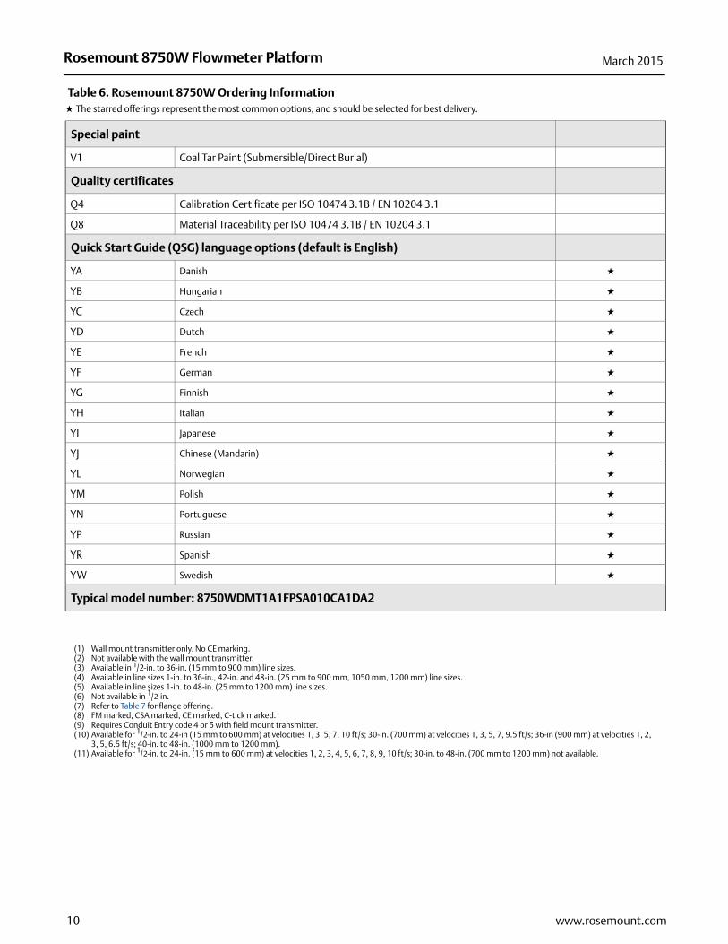
Special paint
V1 Coal Tar Paint (Submersible/Direct Burial)
Quality certificates
Q4 Calibration Certificate per ISO 10474 3.1B / EN 10204 3.1
Q8 Material Traceability per ISO 10474 3.1B / EN 10204 3.1
Quick Start Guide (QSG) language options (default is English)
YA Danish H
YB Hungarian H
YC Czech H
YD Dutch H
YE French H
YF German H
YG Finnish H
YH Italian H
YI Japanese H
YJ Chinese (Mandarin) H
YL Norwegian H
YM Polish H
YN Portuguese H
YP Russian H
YR Spanish H
YW Swedish H
Typical model number: 8750WDMT1A1FPSA010CA1DA2
(1) Wall mount transmitter only. No CE marking.(2) Not available with the wall mount transmitter.(3) Available in 1/2-in. to 36-in. (15 mm to 900 mm) line sizes.(4) Available in line sizes 1-in. to 36-in., 42-in. and 48-in. (25 mm to 900 mm, 1050 mm, 1200 mm) line sizes.(5) Available in line sizes 1-in. to 48-in. (25 mm to 1200 mm) line sizes.(6) Not available in 1/2-in.(7) Refer to Table 7 for flange offering.(8) FM marked, CSA marked, CE marked, C-tick marked.(9) Requires Conduit Entry code 4 or 5 with field mount transmitter.(10) Available for 1/2-in. to 24-in (15 mm to 600 mm) at velocities 1, 3, 5, 7, 10 ft/s; 30-in. (700 mm) at velocities 1, 3, 5, 7, 9.5 ft/s; 36-in (900 mm) at velocities 1, 2,
3, 5, 6.5 ft/s; 40-in. to 48-in. (1000 mm to 1200 mm).(11) Available for 1/2-in. to 24-in. (15 mm to 600 mm) at velocities 1, 2, 3, 4, 5, 6, 7, 8, 9, 10 ft/s; 30-in. to 48-in. (700 mm to 1200 mm) not available.
Table 6. Rosemount 8750W Ordering InformationH The starred offerings represent the most common options, and should be selected for best delivery.
10 www.rosemount.com
Rosemount 8750W Flowmeter PlatformMarch 2015
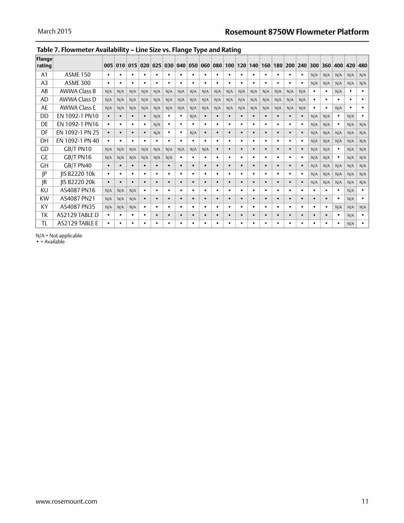
Table 7. Flowmeter Availability – Line Size vs. Flange Type and Rating
N/A = Not applicable• = Available
Flange rating 005 010 015 020 025 030 040 050 060 080 100 120 140 160 180 200 240 300 360 400 420 480
A1 ASME 150 • • • • • • • • • • • • • • • • • N/A N/A N/A N/A N/A
A3 ASME 300 • • • • • • • • • • • • • • • • • N/A N/A N/A N/A N/A
AB AWWA Class B N/A N/A N/A N/A N/A N/A N/A N/A N/A N/A N/A N/A N/A N/A N/A N/A N/A • • N/A • •
AD AWWA Class D N/A N/A N/A N/A N/A N/A N/A N/A N/A N/A N/A N/A N/A N/A N/A N/A N/A • • • • •
AE AWWA Class E N/A N/A N/A N/A N/A N/A N/A N/A N/A N/A N/A N/A N/A N/A N/A N/A N/A • • N/A • •
DD EN 1092-1 PN10 • • • • N/A • • N/A • • • • • • • • • N/A N/A • N/A •
DE EN 1092-1 PN16 • • • • N/A • • • • • • • • • • • • N/A N/A • N/A N/A
DF EN 1092-1 PN 25 • • • • N/A • • N/A • • • • • • • • • N/A N/A N/A N/A N/A
DH EN 1092-1 PN 40 • • • • • • • • • • • • • • • • • N/A N/A N/A N/A N/A
GD GB/T PN10 N/A N/A N/A N/A N/A N/A N/A N/A N/A • • • • • • • • N/A N/A • N/A N/A
GE GB/T PN16 N/A N/A N/A N/A N/A N/A • • • • • • • • • • • N/A N/A • N/A N/A
GH GB/T PN40 • • • • • • • • • • • • • • • • • N/A N/A N/A N/A N/A
JP JIS B2220 10k • • • • • • • • • • • • • • • • • N/A N/A N/A N/A N/A
JR JIS B2220 20k • • • • • • • • • • • • • • • • • N/A N/A N/A N/A N/A
KU AS4087 PN16 N/A N/A N/A • • • • • • • • • • • • • • • • • N/A •
KW AS4087 PN21 N/A N/A N/A • • • • • • • • • • • • • • • • • N/A •
KY AS4087 PN35 N/A N/A N/A • • • • • • • • • • • • • • • • N/A N/A N/A
TK AS2129 TABLE D • • • • • • • • • • • • • • • • • • • • N/A •
TL AS2129 TABLE E • • • • • • • • • • • • • • • • • • • • N/A •
11www.rosemount.com
Rosemount 8750W Flowmeter Platform March 2015
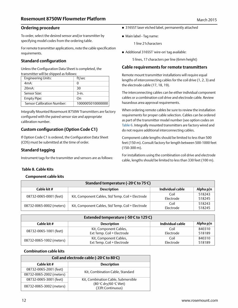
Ordering procedure
To order, select the desired sensor and/or transmitter by specifying model codes from the ordering table.
For remote transmitter applications, note the cable specification requirements.
Standard configuration
Unless the Configuration Data Sheet is completed, the transmitter will be shipped as follows:
Integrally Mounted Rosemount 8750W Transmitters are factory configured with the paired sensor size and appropriate calibration number.
Custom configuration (Option Code C1)
If Option Code C1 is ordered, the Configuration Data Sheet (CDS) must be submitted at the time of order.
Standard tagging
Instrument tags for the transmitter and sensors are as follows:
316SST laser etched label, permanently attached
Main label - Tag name:
1 line 21characters
Additional 316SST 'wire-on' tag available:
5 lines, 17 characters per line (6mm height)
Cable requirements for remote transmitters
Remote mount transmitter installations will require equal lengths of interconnecting cables for the coil drive (1, 2, 3) and the electrode cable (17, 18, 19).
The interconnecting cables can be either individual component cables or a combination coil drive and electrode cable. Review hazardous area approval requirements.
When ordering remote cables be sure to review the installation requirements for proper cable selection. Cables can be ordered as part of the transmitter model number (see option codes on Table 6. Integrally mounted transmitters are factory wired and do not require additional interconnecting cables.
Component cable lengths should be limited to less than 500 feet (150 m). Consult factory for length between 500-1000 feet (150-300 m).
For installations using the combination coil drive and electrode cable, lengths should be limited to less than 330 feet (100 m).
Table 8. Cable Kits
Engineering Units: ft/sec4mA: 020mA: 30Sensor Size: 3-in.Empty Pipe: On Sensor Calibration Number: 1000005010000000
Component cable kits
Standard temperature (-20°C to 75°C)
Cable kit # Description Individual cable Alpha p/n
08732-0065-0001 (feet) Kit, Component Cables, Std Temp. Coil + ElectrodeCoil
Electrode518243518245
08732-0065-0002 (meters) Kit, Component Cables, Std Temp. Coil + ElectrodeCoil
Electrode518243518245
Extended temperature (-50°C to 125°C)
Cable kit # Description Individual cable Alpha p/n
08732-0065-1001 (feet)Kit, Component Cables,
Ext Temp. Coil + ElectrodeCoil
Electrode840310 518189
08732-0065-1002 (meters)Kit, Component Cables,
Ext Temp. Coil + ElectrodeCoil
Electrode840310 518189
Combination cable kits
Coil and electrode cable (-20°C to 80°C)
Cable kit # Description08732-0065-2001 (feet)
Kit, Combination Cable, Standard08732-0065-2002 (meters)
08732-0065-3001 (feet) Kit, Combination Cable, Submersible(80 °C dry/60 °C Wet)
(33ft Continuous)08732-0065-3002 (meters)
12 www.rosemount.com
Rosemount 8750W Flowmeter PlatformMarch 2015
Product Specifications
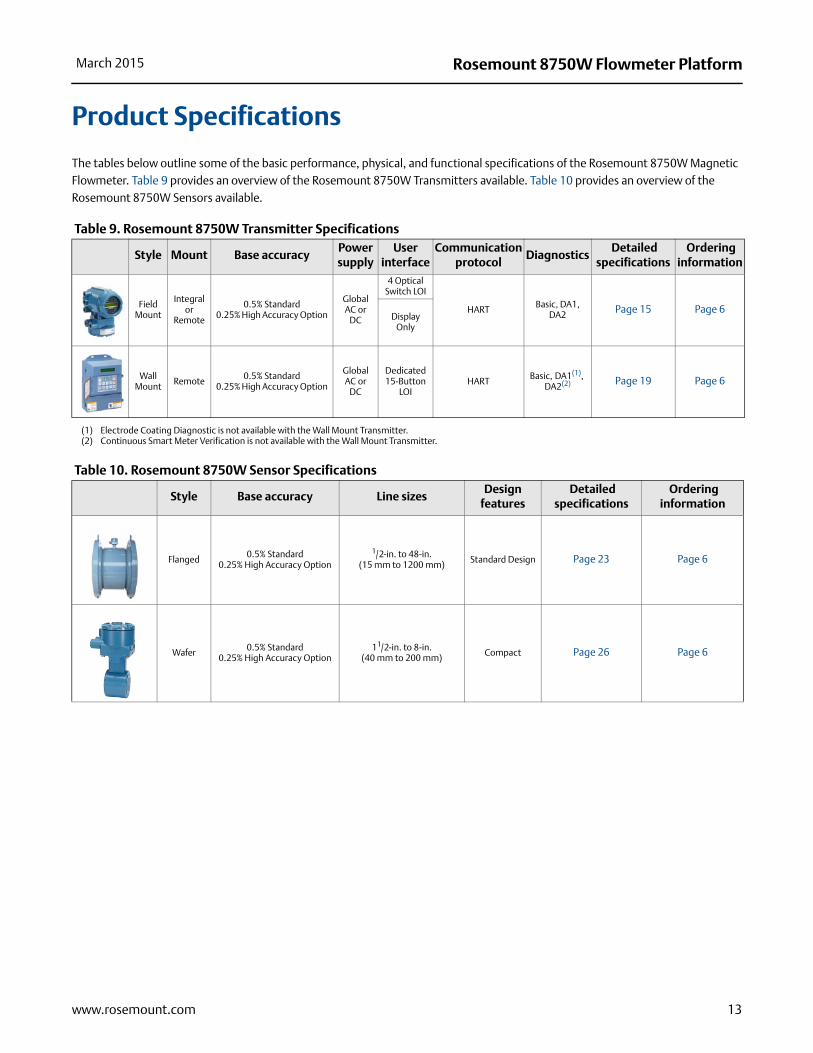
The tables below outline some of the basic performance, physical, and functional specifications of the Rosemount 8750W Magnetic Flowmeter. Table 9 provides an overview of the Rosemount 8750W Transmitters available. Table 10 provides an overview of the Rosemount 8750W Sensors available.
Table 9. Rosemount 8750W Transmitter Specifications
Table 10. Rosemount 8750W Sensor Specifications
Style Mount Base accuracyPower supply
User interface
Communication protocol
Diagnostics Detailed
specifications Ordering
information
Field Mount
Integral or
Remote
0.5% Standard 0.25% High Accuracy Option
Global AC or
DC
4 Optical Switch LOI
HART Basic, DA1, DA2 Page 15 Page 6
Display Only
Wall Mount Remote 0.5% Standard
0.25% High Accuracy Option
Global AC or
DC
Dedicated 15-Button
LOIHART Basic, DA1(1),
DA2(2)
(1) Electrode Coating Diagnostic is not available with the Wall Mount Transmitter.(2) Continuous Smart Meter Verification is not available with the Wall Mount Transmitter.
Page 19 Page 6
Style Base accuracy Line sizesDesign
features Detailed
specifications Ordering
information
Flanged 0.5% Standard 0.25% High Accuracy Option
1/2-in. to 48-in. (15 mm to 1200 mm) Standard Design Page 23 Page 6
Wafer 0.5% Standard 0.25% High Accuracy Option
11/2-in. to 8-in. (40 mm to 200 mm) Compact Page 26 Page 6
13www.rosemount.com

Rosemount 8750W Flowmeter Platform March 2015
14 www.rosemount.com
Table 11. Lining Material Selection
Table 12. Electrode Selection
Table 13. Process Reference Options
Table 14. Process Reference Installation
Liner material General characteristics
PTFE • Chemical resistance
• Excellent high temperature capabilities
• -20 to 248 °F (-29 to 120 °C)
Polyurethane • Limited chemical resistance
• Excellent abrasion resistance for slurries with small and medium particles
• 0 to 140 °F (-18 to 60 °C)
• Typically applied in clean water
Neoprene • Very good abrasion resistance for small and medium particles
• Better chemical resistance than polyurethane
• Typically applied in water with chemicals, and sea water
• 0 to 176 °F (-18 to 80 °C)
Electrode material General characteristics
316L Stainless Steel
• Good corrosion resistance
• Good abrasion resistance
• Not recommended for sulfuric or hydrochloric acids
Nickel Alloy 276(UNS N10276)
• Better corrosion resistance
• High strength
• Good in slurry applications
• Effective in oxidizing fluids
Electrode type General characteristics
Standard Measurement• Lowest cost
• Good for most applications
Measurement + Reference Electrode (Also see Table 13 and Table 14 for grounding options and installation
• Low cost grounding option especially for large line sizes
• Minimum conductivity of 100 microSiemens/cm
• Not recommended for electrolytic or galvanic corrosion applications
Bulletnose• Extended head protrudes into the
flow stream for self-cleaning
• Best option for coating processes
Grounding options General characteristics
No Grounding Options (grounding straps)
• Acceptable for conductive unlined pipe
• Grounding straps provided at no cost
Reference Electrode
• Same material as measurement electrodes
• Sufficient grounding option when process fluid conductivity is greater than 100 microSiemens/cm
• Not recommended in electrolysis applications, galvanic corrosion applications, or applications where the electrodes may coat.
Grounding Rings
• Low conductivity process fluids
• Cathodic or electrolysis applications that may have stray currents in or around the process
• Variety of materials for process fluid compatibility
Type of pipe Grounding straps Grounding rings Reference electrode Lining protectors
Conductive unlined pipe Acceptable Not Required Not Required Not Required
Conductive lined pipe Not Acceptable Acceptable Acceptable Acceptable
Non-conductive pipe Not Acceptable Acceptable Not Acceptable Acceptable
Rosemount 8750W Flowmeter PlatformMarch 2015
15www.rosemount.com
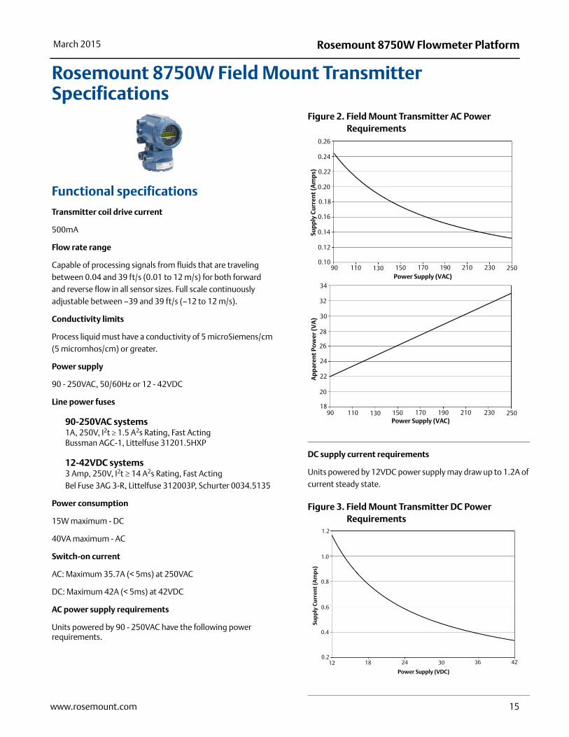
Rosemount 8750W Field Mount Transmitter Specifications
Functional specifications
Transmitter coil drive current
500mA
Flow rate range
Capable of processing signals from fluids that are traveling between 0.04 and 39 ft/s (0.01 to 12 m/s) for both forward and reverse flow in all sensor sizes. Full scale continuously adjustable between –39 and 39 ft/s (–12 to 12 m/s).
Conductivity limits
Process liquid must have a conductivity of 5 microSiemens/cm (5 micromhos/cm) or greater.
Power supply
90 - 250VAC, 50/60Hz or 12 - 42VDC
Line power fuses
90-250VAC systems1A, 250V, I2t 1.5 A2s Rating, Fast ActingBussman AGC-1, Littelfuse 31201.5HXP
12-42VDC systems3 Amp, 250V, I2t 14 A2s Rating, Fast ActingBel Fuse 3AG 3-R, Littelfuse 312003P, Schurter 0034.5135
Power consumption
15W maximum - DC
40VA maximum - AC
Switch-on current
AC: Maximum 35.7A (< 5ms) at 250VAC
DC: Maximum 42A (< 5ms) at 42VDC
AC power supply requirements
Units powered by 90 - 250VAC have the following power requirements.
Figure 2. Field Mount Transmitter AC Power Requirements
DC supply current requirements
Units powered by 12VDC power supply may draw up to 1.2A of current steady state.
Figure 3. Field Mount Transmitter DC Power Requirements
Sup
ply
Cu
rren
t (A
mp
s)A
pp
aren
t Po
wer
(VA
)
Power Supply (VAC)
Power Supply (VAC)
0.22
0.18
0.16
0.12
0.24
0.14
0.10
0.26
0.20
90 170 230150130 210190110 250
18
20
22
24
26
28
30
32
34
90 170 230150130 210190110 250
Sup
ply
Cu
rren
t (A
mp
s)
Power Supply (VDC)
0.8
1.2
1.0
0.6
0.4
0.21812 24 30 36 42
Rosemount 8750W Flowmeter Platform March 2015
Ambient temperature limits
Operating–40 to 140 °F (–40 to 60 °C) without local operator interface
–4 to 140 °F (–20 to 60 °C) with local operator interface
The Local Operator Interface (LOI) will not display at temperatures below -20°C
Storage–40 to 185 °F (–40 to 85 °C) without local operator interface
–22 to 176 °F (–30 to 80 °C) with local operator interface
Humidity limits
0–95% RH to 140 °F (60 °C)
Altitude
2000 meters maximum
Enclosure rating
Type 4X, IEC 60529, IP66 (transmitter)
Transient protection rating
Built in transient protection that conforms to:
IEC 61000-4-4 for burst currents
IEC 61000-4-5 for surge currents
Turn-on time
5 minutes to rated accuracy from power up
5 seconds from power interruption
Start-up time
50ms from zero flow
Low Flow cut-off
Adjustable between 0.01 and 38.37 ft/s (0.003 and 11.7 m/s). Below selected value, output is driven to the zero flow rate signal level.
Overrange capability
Signal output will remain linear until 110% of upper range value or 44 ft/s (13 m/s). The signal output will remain constant above these values. Out of range message displayed on LOI and the Field Communicator.
Damping
Adjustable between 0 and 256 seconds
Advanced diagnostics capabilities
BasicSelf testTransmitter faultsAnalog output testPulse output testTunable empty pipeReverse flowCoil circuit faultElectronics temperatureCoil currentElectrode saturation
Process diagnostics (DA1)Ground/wiring faultHigh process noiseElectrode coating diagnostic
SMART Meter Verification (DA2)
SMART Meter Verification (continuous or on-demand)4-20mA loop verification
Output signals
Analog output adjustment
4–20mA, switch-selectable as internally or externally powered.
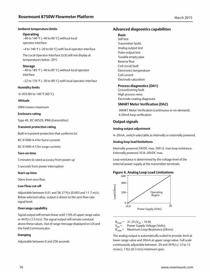
Analog loop load limitations
Internally powered 24VDC max, 500 max loop resistance.Externally powered 10.8–30VDC max.
Loop resistance is determined by the voltage level of the external power supply at the transmitter terminals:
Figure 4. Analog Loop Load Limitations
The analog output is automatically scaled to provide 4mA at lower range value and 20mA at upper range value. Full scale continuously adjustable between -39 and 39 ft/s (-12 to 12 m/sec), 1 ft/s (0.3 m/s) minimum span.
Rmax = 31.25 (Vps – 10.8)Vps = Power Supply Voltage (Volts)Rmax = Maximum Loop Resistance (Ohms)
Power Supply (Volts)
Load
(Ohm
s)
OperatingRegion
600
10.8 30
400
200
0
16 www.rosemount.com

Rosemount 8750W Flowmeter PlatformMarch 2015
HART Communications is a digital flow signal. The digital signal is superimposed on the 4–20mA signal and is available for the control system interface. A minimum of 250 loop resistance is required for HART Communications.
Scalable pulse frequency adjustment
0-10,000Hz, switch-selectable as internally or externally powered. Pulse value can be set to equal desired volume in selected engineering units. Pulse width adjustable from 0.1 to 650 ms.
Internally powered: Outputs up to 12VDC
Externally powered: Input 5 - 28VDC
Output testing
Analog output testTransmitter may be commanded to supply a specified current between 3.5 and 23mA.
Pulse output testTransmitter may be commanded to supply a specified frequency between 1 and 10,000Hz.
Optional discrete output function (AX option)
Externally powered at 5 - 28VDC, 240mA max, solid state switch closure to indicate either:
Reverse flow Activates switch closure output when reverse flow is detected.
Zero flow Activates switch closure output when flow goes to 0 ft/s or below low flow cutoff.
Empty pipeActivates switch closure output when an empty pipe condition is detected.
Transmitter faultsActivates switch closure output when a transmitter fault is detected.
Flow limit 1, Flow limit 2Activates switch closure output when the transmitter measures a flow rate that meets the conditions established for this alert. There are two independent flow limit alerts that can be configured as discrete outputs.
Totalizer limitActivates switch closure output when the transmitter measures a total flow that meets the conditions established for this alert.
Diagnostic statusActivates switch closure output when the transmitter detects a condition that meets the configured criteria of this output.
Optional discrete input function (AX option)
Externally powered at 5 - 28VDC, 1.4 - 20mA to activate switch closure to indicate either:
Net total reset Resets the net totalizer value to zero.
Positive zero return (PZR) Forces outputs of the transmitter to zero flow.
Security lockout
Security lockout switch on the electronics board can be set to deactivate all LOI and HART-based communicator functions to protect configuration variables from unwanted or accidental change.
LOI lockout
The display can be manually locked to prevent unintentional configuration changes. The display lock can be activated through a HART communication device, or by holding the UP arrow for 3 seconds and then following the on-screen instructions. When the display lock is activated, a lock symbol will appear in the lower right hand corner of the display. To deactivate the display lock, hold the UP arrow for 3 seconds and follow the on-screen instructions.
Display auto lock can be configured from the LOI with the following settings: OFF, 1 Minute, or 10 Minutes
Sensor compensation
Rosemount sensors are calibrated in a flow lab at the factory and are assigned a calibration number. The calibration number must be entered into the transmitter, enabling interchangeability of sensors without calculations or a compromise in standard accuracy.
8750W Transmitters and other manufacturers’ sensors can be calibrated at known process conditions or at the Rosemount NIST-Traceable Flow Facility. Transmitters calibrated on site require a two-step procedure to match a known flow rate. This procedure can be found in the operations manual.
17www.rosemount.com

Rosemount 8750W Flowmeter Platform March 2015
Performance specifications
System specifications are given using the frequency output and with the unit at reference conditions.
Accuracy
Includes the combined effects of linearity, hysteresis, repeatability, and calibration uncertainty.
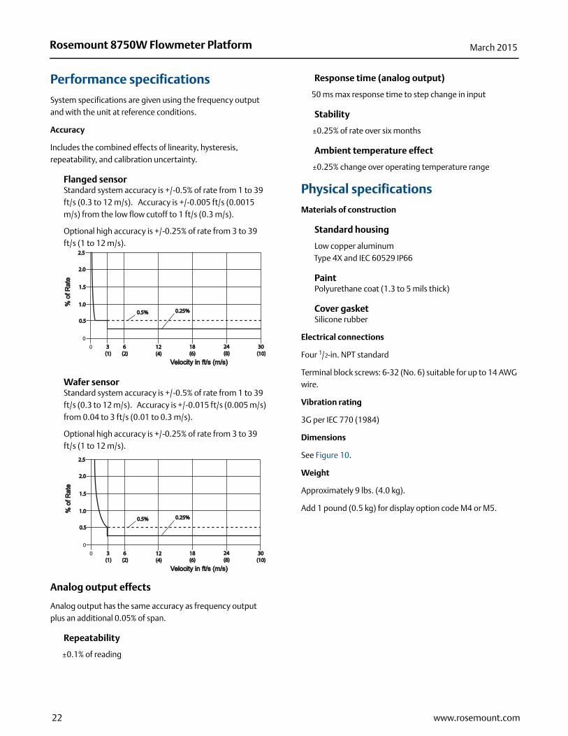
Flanged sensorStandard system accuracy is +/-0.5% of rate from 1 to 39 ft/s (0.3 to 12 m/s). Accuracy is +/-0.005 ft/s (0.0015 m/s) from the low flow cutoff to 1 ft/s (0.3 m/s).
Optional high accuracy is +/-0.25% of rate from 3 to 39 ft/s (1 to 12 m/s).
Wafer sensorStandard system accuracy is +/-0.5% of rate from 1 to 39 ft/s (0.3 to 12 m/s). Accuracy is +/-0.015 ft/s (0.005 m/s) from 0.04 to 3 ft/s (0.01 to 0.3 m/s).
Optional high accuracy is +/-0.25% of rate from 3 to 39 ft/s (1 to 12 m/s).
Analog output effects
Analog output has the same accuracy as frequency output plus an additional ±4A at room temperature.
Repeatability
±0.1% of reading
Response time (analog output)
20 ms max response time to step change in input
Stability
±0.25% of rate over six months
Ambient temperature effect
±0.25% change over operating temperature range
Physical specifications
Materials of construction
Standard housing
Low copper aluminumType 4X and IEC 60529 IP66
PaintPolyurethane coat (1.3 to 5 mils thick)
Cover gasketBuna-N
Electrical connectionsConduit entries: 1/2-in. NPT standard. (Optional third connection available).
Terminal block screws: 6-32 (No. 6) suitable for up to 14 AWG wire.
Safety grounding screws: external stainless assembly, M5; internal 8-32 (No. 8)
Vibration rating
3G per IEC 61298
Dimensions
See Figure 9.
Weight
Approximately 7 lbs. (3.2 kg).
Add 1 pound (0.5 kg) for display option code M4 or M5.
0
0.50.5
1.01.0
1.51.5
2.02.0
2.52.5
0 3 3 (1)(1)
6 6 (2)(2)
12 12 (4)(4)
18 18 (6)(6)
24 24 (8)(8)
30 30 (10)(10)
Velocity in ft/s (m/s)Velocity in ft/s (m/s)
% o
f Rat
e%
of R
ate
0.5%0.5% 0.25%0.25%
0
0.50.5
1.01.0
1.51.5
2.02.0
2.52.5
0 3 3 (1)(1)
6 6 (2)(2)
12 12 (4)(4)
18 18 (6)(6)
24 24 (8)(8)
30 30 (10)(10)
Velocity in ft/s (m/s)Velocity in ft/s (m/s)
% o
f Rat
e%
of R
ate
0.5%0.5% 0.25%0.25%
18 www.rosemount.com
Rosemount 8750W Flowmeter PlatformMarch 2015
19www.rosemount.com
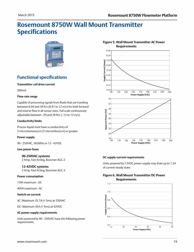
Rosemount 8750W Wall Mount Transmitter Specifications
Functional specifications
Transmitter coil drive current
500mA
Flow rate range
Capable of processing signals from fluids that are traveling between 0.04 and 39 ft/s (0.01 to 12 m/s) for both forward and reverse flow in all sensor sizes. Full scale continuously adjustable between –39 and 39 ft/s (–12 to 12 m/s).
Conductivity limits
Process liquid must have a conductivity of 5 microSiemens/cm (5 micromhos/cm) or greater.
Power supply
90 - 250VAC, 50/60Hz or 12 - 42VDC
Line power fuses
90-250VAC systems2 Amp, Fast Acting, Bussman AGC-2
12-42VDC systems3 Amp, Fast Acting, Bussman AGC-3
Power consumption
15W maximum - DC
40VA maximum - AC
Switch-on current
AC: Maximum 35.7A (< 5ms) at 250VAC
DC: Maximum 42A (< 5ms) at 42VDC
AC power supply requirements
Units powered by 90 - 250VAC have the following power requirements.
Figure 5. Wall Mount Transmitter AC Power Requirements
DC supply current requirements
Units powered by 12VDC power supply may draw up to 1.2A of current steady state.
Figure 6. Wall Mount Transmitter DC Power Requirements
Sup
ply
Cu
rren
t (A
mp
s)A
pp
aren
t Po
wer
(VA
)
Power Supply (VAC)
Power Supply (VAC)
0.22
0.18
0.16
0.12
0.24
0.14
0.10
0.26
0.20
90 170 230150130 210190110 250
18
20
22
24
26
28
30
32
34
90 170 230150130 210190110 250
Sup
ply
Cu
rren
t (A
mp
s)
Power Supply (VDC)
0.8
1.2
1.0
0.6
0.4
0.21812 24 30 36 42
Rosemount 8750W Flowmeter Platform March 2015
Ambient temperature limits
Operating–40 to 165 °F (–40 to 74 °C) without local operator interface
–20 to 140 °F (–29 to 60 °C) with local operator interface
The Local Operator Interface (LOI) will not display at temperatures below -20°C
Storage–40 to 176 °F (–40 to 80 °C) with and without local operator interface
Humidity limits
0–95% RH to 120 °F (49 °C), decrease linearly to 10% RH at 130 °F (54 °C)
Altitude
2000 meters maximum
Enclosure rating
Type 4X, IEC 60529, IP66 (transmitter)
Transient protection rating
Built in transient protection that conforms to:
IEC 61000-4-4 for burst currents
IEC 61000-4-5 for surge currents
Turn-on time
5 minutes to rated accuracy from power up
5 seconds from power interruption
Start-up time
50ms from zero flow
Low Flow cut-off
Adjustable between 0.01 and 38.37 ft/s (0.003 and 11.7 m/s). Below selected value, output is driven to the zero flow rate signal level.
Overrange capability
Signal output will remain linear until 110% of upper range value or 44 ft/s (13 m/s). The signal output will remain constant above these values. Out of range message displayed on LOI and the Field Communicator.
Damping
Adjustable between 0 and 256 seconds
Advanced diagnostics capabilities
BasicSelf testTransmitter faultsAnalog output testPulse output testTunable empty pipeReverse flowCoil circuit faultElectronics temperature
Process diagnostics (DA1)Ground/wiring faultHigh process noise
SMART Meter Verification (DA2)
SMART Meter Verification (on-demand)4-20mA loop verification
Output signals
Analog output adjustment
4–20mA, switch-selectable as internally or externally powered.
Analog loop load limitations
Internally powered 24VDC max, 500 max loop resistance
Externally powered 10.8 - 30VDC max.
Loop resistance is determined by the voltage level of the external power supply at the transmitter terminals:
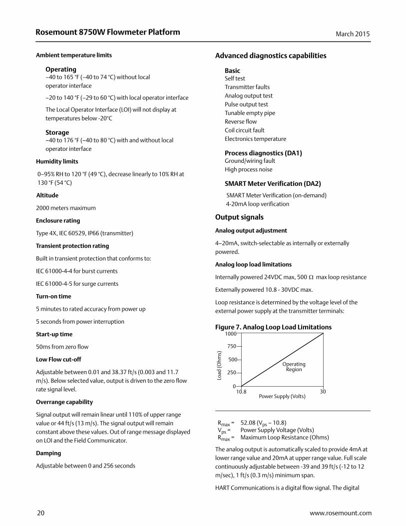
Figure 7. Analog Loop Load Limitations
The analog output is automatically scaled to provide 4mA at lower range value and 20mA at upper range value. Full scale continuously adjustable between -39 and 39 ft/s (-12 to 12 m/sec), 1 ft/s (0.3 m/s) minimum span.
HART Communications is a digital flow signal. The digital
Rmax = 52.08 (Vps – 10.8)Vps = Power Supply Voltage (Volts)Rmax = Maximum Loop Resistance (Ohms)
Power Supply (Volts)
Load
(Ohm
s)
Operating Region
1000
10.8 30
750
250
0
500
20 www.rosemount.com
Rosemount 8750W Flowmeter PlatformMarch 2015
signal is superimposed on the 4–20mA signal and is available for the control system interface. A minimum of 250 loop resistance is required for HART communications.
Scalable pulse frequency adjustment
0-10,000HzPulse value can be set to equal desired volume in selected engineering units. Pulse width adjustable from 1.5 to 500 ms. Below 1.5msec pulse width automatically switches to 50% duty cycle.
Externally powered: Input 5 - 24VDC
Output testing
Analog output testTransmitter may be commanded to supply a specified current between 3.5 and 23mA.
Pulse output testTransmitter may be commanded to supply a specified frequency between 1 and 10,000Hz.
Optional discrete output function (AX option)
Externally powered at 5 - 28VDC, 240mA max, solid state switch closure to indicate either:
Reverse flow Activates switch closure output when reverse flow is detected.
Zero flow Activates switch closure output when flow goes to 0 ft/s or below low flow cutoff.
Empty pipeActivates switch closure output when an empty pipe condition is detected.
Transmitter faultsActivates switch closure output when a transmitter fault is detected.
Flow limit 1, Flow limit 2Activates switch closure output when the transmitter measures a flow rate that meets the conditions established for this alert. There are two independent flow limit alerts that can be configured as discrete outputs.
Totalizer limitActivates switch closure output when the transmitter measures a total flow that meets the conditions established for this alert.
Diagnostic statusActivates switch closure output when the transmitter detects a condition that meets the configured criteria of this output.
Optional discrete input function (AX option)
Externally powered at 5 - 28VDC, 1.4 - 20mA to activate switch closure to indicate either:
Net total reset Resets the net totalizer value to zero.
Positive zero return (PZR) Forces outputs of the transmitter to zero flow.
Security lockout
Security lockout switch on the electronics board can be set to protect configuration variables from unwanted or accidental changes.
Sensor compensation
Rosemount sensors are calibrated in a flow lab at the factory and are assigned a calibration number. The calibration number must be entered into the transmitter, enabling interchangeability of sensors without calculations or a compromise in standard accuracy.
8750W Transmitters and other manufacturers’ sensors can be calibrated at known process conditions or at the Rosemount NIST-Traceable Flow Facility. Transmitters calibrated on site require a two-step procedure to match a known flow rate. This procedure can be found in the operations manual.
21www.rosemount.com
Rosemount 8750W Flowmeter Platform March 2015
Performance specifications
System specifications are given using the frequency output and with the unit at reference conditions.
Accuracy
Includes the combined effects of linearity, hysteresis, repeatability, and calibration uncertainty.
Flanged sensorStandard system accuracy is +/-0.5% of rate from 1 to 39 ft/s (0.3 to 12 m/s). Accuracy is +/-0.005 ft/s (0.0015 m/s) from the low flow cutoff to 1 ft/s (0.3 m/s).
Optional high accuracy is +/-0.25% of rate from 3 to 39 ft/s (1 to 12 m/s).
Wafer sensorStandard system accuracy is +/-0.5% of rate from 1 to 39 ft/s (0.3 to 12 m/s). Accuracy is +/-0.015 ft/s (0.005 m/s) from 0.04 to 3 ft/s (0.01 to 0.3 m/s).
Optional high accuracy is +/-0.25% of rate from 3 to 39 ft/s (1 to 12 m/s).
Analog output effects
Analog output has the same accuracy as frequency output plus an additional 0.05% of span.
Repeatability
±0.1% of reading
Response time (analog output)
50 ms max response time to step change in input
Stability
±0.25% of rate over six months
Ambient temperature effect
±0.25% change over operating temperature range
Physical specifications
Materials of construction
Standard housing
Low copper aluminumType 4X and IEC 60529 IP66
PaintPolyurethane coat (1.3 to 5 mils thick)
Cover gasketSilicone rubber
Electrical connections
Four 1/2-in. NPT standard
Terminal block screws: 6-32 (No. 6) suitable for up to 14 AWG wire.
Vibration rating
3G per IEC 770 (1984)
Dimensions
See Figure 10.
Weight
Approximately 9 lbs. (4.0 kg).
Add 1 pound (0.5 kg) for display option code M4 or M5.
0
0.50.5
1.01.0
1.51.5
2.02.0
2.52.5
0 3 3 (1)(1)
6 6 (2)(2)
12 12 (4)(4)
18 18 (6)(6)
24 24 (8)(8)
30 30 (10)(10)
Velocity in ft/s (m/s)Velocity in ft/s (m/s)
% o
f Rat
e%
of R
ate
0.5%0.5% 0.25%0.25%
0
0.50.5
1.01.0
1.51.5
2.02.0
2.52.5
0 3 3 (1)(1)
6 6 (2)(2)
12 12 (4)(4)
18 18 (6)(6)
24 24 (8)(8)
30 30 (10)(10)
Velocity in ft/s (m/s)Velocity in ft/s (m/s)
% o
f Rat
e%
of R
ate
0.5%0.5% 0.25%0.25%
22 www.rosemount.com
Rosemount 8750W Flowmeter PlatformMarch 2015
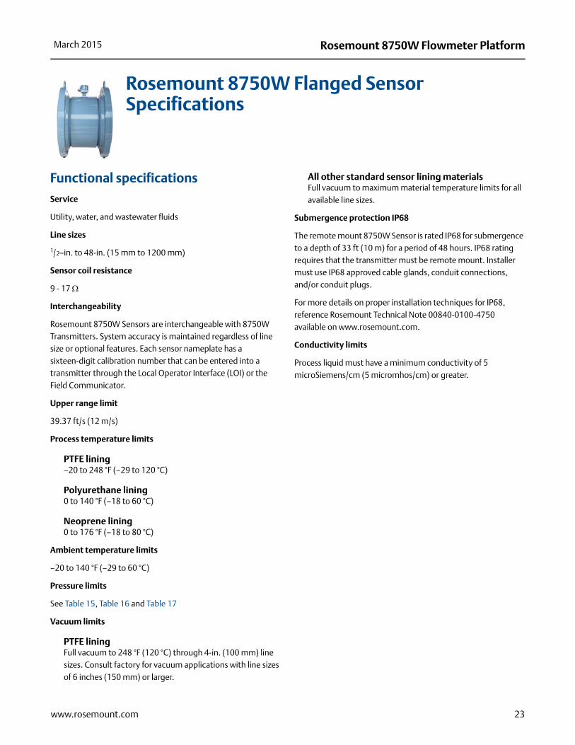
Rosemount 8750W Flanged Sensor Specifications
Functional specifications
Service
Utility, water, and wastewater fluids
Line sizes
1/2–in. to 48-in. (15 mm to 1200 mm)
Sensor coil resistance
9 - 17
Interchangeability
Rosemount 8750W Sensors are interchangeable with 8750W Transmitters. System accuracy is maintained regardless of line size or optional features. Each sensor nameplate has a sixteen-digit calibration number that can be entered into a transmitter through the Local Operator Interface (LOI) or the Field Communicator.
Upper range limit
39.37 ft/s (12 m/s)
Process temperature limits
PTFE lining–20 to 248 °F (–29 to 120 °C)
Polyurethane lining0 to 140 °F (–18 to 60 °C)
Neoprene lining0 to 176 °F (–18 to 80 °C)
Ambient temperature limits
–20 to 140 °F (–29 to 60 °C)
Pressure limits
See Table 15, Table 16 and Table 17
Vacuum limits
PTFE liningFull vacuum to 248 °F (120 °C) through 4-in. (100 mm) line sizes. Consult factory for vacuum applications with line sizes of 6 inches (150 mm) or larger.
All other standard sensor lining materialsFull vacuum to maximum material temperature limits for all available line sizes.
Submergence protection IP68
The remote mount 8750W Sensor is rated IP68 for submergence to a depth of 33 ft (10 m) for a period of 48 hours. IP68 rating requires that the transmitter must be remote mount. Installer must use IP68 approved cable glands, conduit connections, and/or conduit plugs.
For more details on proper installation techniques for IP68, reference Rosemount Technical Note 00840-0100-4750 available on www.rosemount.com.
Conductivity limits
Process liquid must have a minimum conductivity of 5 microSiemens/cm (5 micromhos/cm) or greater.
23www.rosemount.com
Rosemount 8750W Flowmeter Platform March 2015
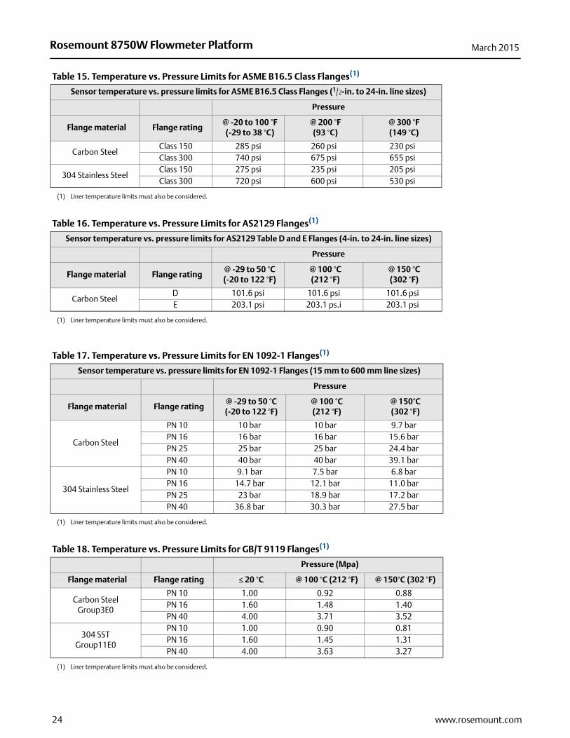
Table 15. Temperature vs. Pressure Limits for ASME B16.5 Class Flanges(1)
Sensor temperature vs. pressure limits for ASME B16.5 Class Flanges (1/2-in. to 24-in. line sizes)
Pressure
Flange material Flange rating@ -20 to 100 °F(-29 to 38 °C)
@ 200 °F(93 °C)
@ 300 °F(149 °C)
Carbon SteelClass 150 285 psi 260 psi 230 psiClass 300 740 psi 675 psi 655 psi
304 Stainless SteelClass 150 275 psi 235 psi 205 psiClass 300 720 psi 600 psi 530 psi
(1) Liner temperature limits must also be considered.
Table 16. Temperature vs. Pressure Limits for AS2129 Flanges(1)
Sensor temperature vs. pressure limits for AS2129 Table D and E Flanges (4-in. to 24-in. line sizes)
Pressure
Flange material Flange rating@ -29 to 50 °C(-20 to 122 °F)
@ 100 °C(212 °F)
@ 150 °C(302 °F)
Carbon SteelD 101.6 psi 101.6 psi 101.6 psiE 203.1 psi 203.1 ps.i 203.1 psi
(1) Liner temperature limits must also be considered.
Table 17. Temperature vs. Pressure Limits for EN 1092-1 Flanges(1)
Sensor temperature vs. pressure limits for EN 1092-1 Flanges (15 mm to 600 mm line sizes)
Pressure
Flange material Flange rating@ -29 to 50 °C(-20 to 122 °F)
@ 100 °C(212 °F)
@ 150°C(302 °F)
Carbon Steel
PN 10 10 bar 10 bar 9.7 barPN 16 16 bar 16 bar 15.6 barPN 25 25 bar 25 bar 24.4 barPN 40 40 bar 40 bar 39.1 bar
304 Stainless Steel
PN 10 9.1 bar 7.5 bar 6.8 barPN 16 14.7 bar 12.1 bar 11.0 barPN 25 23 bar 18.9 bar 17.2 barPN 40 36.8 bar 30.3 bar 27.5 bar
(1) Liner temperature limits must also be considered.
Table 18. Temperature vs. Pressure Limits for GB/T 9119 Flanges(1)
Pressure (Mpa)
Flange material Flange rating 20 °C @ 100 °C (212 °F) @ 150°C (302 °F)
Carbon Steel Group3E0
PN 10 1.00 0.92 0.88PN 16 1.60 1.48 1.40PN 40 4.00 3.71 3.52
304 SSTGroup11E0
PN 10 1.00 0.90 0.81PN 16 1.60 1.45 1.31PN 40 4.00 3.63 3.27
(1) Liner temperature limits must also be considered.
24 www.rosemount.com

Rosemount 8750W Flowmeter PlatformMarch 2015
Physical specifications
Non-wetted materials
Sensor pipeType 304/304L SST
FlangesCarbon steel, Type 304/304L SST
Coil housingRolled carbon steel
PaintPolyurethane coat (1.3 to 5 mils thick)
Process wetted materials
LiningPTFE, Polyurethane, Neoprene
Electrodes316L SST, Nickel Alloy 276 (UNS N10276)
Flat-faced flanges
Flat-faced flanges are manufactured with full-face liners. Available in Neoprene only.
Process connections
ASME B16.5
Class 150: 1/2-in. to 24-in. (15mm to 600mm)
Class 300: 1/2-in. to 24-in. (15mm to 600mm)
AWWA C207Class D: 30-in. and 48-in. (750mm to 1200mm)
Class E: 40-in. and 48-in. (1000mm to 1200mm)
EN 1092-1 PN10: 8-in. to 24-in., 40-in., 48-in. (200 mm to 600mm, 1000mm, 1200mm)
PN16: 4-in. to 24-in., 40-in. (100 mm to 600mm, 1000mm)
PN 25: 8-in. to 24-in. (200 mm to 600mm)
PN40: 1/2-in. to 24-in. (15 mm to 600mm)
AS2129 Table D and E: 1/2-in. to 40-in., 48-in. (15 mm to 1000mm, 1200mm)
AS4087PN16, PN21, PN35: 2-in. to 40-in., 48-in. (5-in. excluded) (50mm to 1000mm, 1200mm)
GB/T9119PN10: 8-in. and 24-in., 40-in., 48-in. (200mm to 600mm, 1000mm, 1200mm)
PN16: 4-in. and 24-in., 40-in. (100mm to 600mm, 1000mm)
PN40: 1/2-in. to 24-in. (15mm to 600mm)
JIS B222010K: 1/2-in. to 24-in. (15mm to 600mm)
20K, 40K: 1/2-in. to 8-in. (15mm to 200mm)
Electrical connections
Conduit entries: 1/2-in. NPT standard.
Terminal block screws: 6-32 (No. 6) suitable for up to 14 AWG wire.
Safety grounding screws: external stainless assembly, M5; internal 8-32 (No. 8)
Process reference electrode - (optional)
A process reference electrode can be installed similarly to the measurement electrodes through the sensor lining on 8750W sensors. It will be made of the same material as the measurement electrodes.
Grounding rings - (optional)
Grounding rings can be installed between the flange and the sensor face on both ends of the sensor. Single ground rings can be installed on either end of the sensor. They have an I.D. slightly larger than the sensor I.D. and an external tab to attach ground wiring. Grounding rings are available in 316L SST and Nickel Alloy 276 (UNS N10276). See Figure 14.
Dimensions
See Figure 11 through Figure 13.
Weight
See Table 20 through Table 26.
Table 19. Temperature vs. Pressure Limits for JIS B2220 Flanges(1)
Pressure (Mpa)
Flange material Flange rating 50 °C (122 °F) @ 120 °C (248 °F)
Carbon Steel 10K 1.4 1.4304 Stainless Steel (15mm to 65mm) 10K 1.4 1.4
304 Stainless Steel (80mm) 10K 1.4 1.0
(1) Liner temperature limits must also be considered.
25www.rosemount.com

Rosemount 8750W Flowmeter Platform March 2015
Rosemount 8750W Wafer Sensor Specifications
Functional specifications
Service
Utility, water and wastewater fluids
Line sizes
11/2-in. to 8-in. (4 mm to 200 mm)
Sensor coil resistance
10 - 18
Interchangeability
Rosemount 8750W Wafer Sensors are interchangeable with 8750W Transmitter. System accuracy is maintained regardless of line size or optional features. Each sensor nameplate has a sixteen-digit calibration number that can be entered into a transmitter through the Local Operator Interface (LOI) or the Field Communicator.
Upper range limit
39.37 ft/s (12 m/s)
Process temperature limits
PTFE lining-20 to 350 °F (-29 to 177 °C)
Ambient temperature limits
–20 to 140 °F (–29 to 60 °C)
Maximum safe working pressure at 100 °F (38 °C)
PTFE liningFull vacuum through 4-in. (100 mm) line sizes. Consult factory for vacuum applications with line sizes of 6-in. (1450 mm) or larger.
Submergence protection IP68
The remote mount 8750W Wafer Sensor is rated IP68 for submergence to a depth of 33 ft (10 m) for a period of 48 hours. IP68 rating requires that the transmitter must be remote mount. Installer must use IP68 approved cable glands, conduit connections, and/or conduit plugs. For more details on proper installation techniques for IP68, reference Rosemount Technical Document 00840-0100-4750 available on www.rosemount.com.
Conductivity limits
Process liquid must have a minimum conductivity of 5 microSiemens/cm (5 micromhos/cm) or greater.
Physical specifications
Non-wetted materials
Sensor body303 SSTCF3M or CF8MType 304/304L
Coil housing Rolled carbon steel
PaintPolyurethane coat (1.3 to 5 mils thick)
Process-wetted materials
LiningPTFE
Electrodes316L SST, Nickel Alloy 276 (UNS N10276)
Process connections
Mounts between these flange configurationsASME B16.5: Class 150, 300EN 1092-1: PN10, PN16, PN25, PN40
JIS B2220: 10K, 20K, AS4087: PN16, PN21, PN35
26 www.rosemount.com

Rosemount 8750W Flowmeter PlatformMarch 2015
27www.rosemount.com
Studs, nuts, and washers
MK2ASME B16.5
Studs, full thread: CS, ASTM A193, Grade B7
Hex nuts: ASTM A194 Grade 2H
Flat washers: CS, Type A, Series N, SAE per ANSI B18.2.1
All items clear, chromate zinc-plated
EN 1092-1
Studs, full thread: CS, ASTM A193, Grade B7
Hex nuts: ASTM A194 Grade 2H; DIN 934 H = D
Flat washers: CS, DIN 125
All items yellow zinc-plated
Electrical connections
Conduit entries: 1/2-in. NPT standard.
Terminal block screws: 6-32 (No. 6) suitable for up to 14 AWG wire.
Safety grounding screws: external stainless assembly, M5; internal 8-32 (No. 8)
Process reference electrode (optional)
A process reference electrode can be installed similarly to the measurement electrodes through the sensor lining. It will be made of the same material as the measurement electrodes.
Grounding rings (optional)
Grounding rings can be installed between the flange and the sensor face on both ends of the sensor. They have an I.D. slightly smaller than the sensor I.D. and an external tab to attach ground wiring. Grounding rings are available in 316L SST and Nickel Alloy 276 (UNS N10276). SeeTable 14.
Dimensions
See Figure 15.
Weight
See Table 27.
Rosemount 8750W Flowmeter Platform March 2015
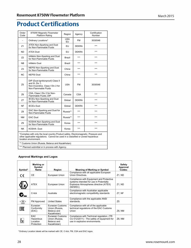
Product CertificationsOrder Code
8750W Magnetic Flowmeter Platform Rating Region Agency Certification
Number
- Ordinary Locations* USA EU FM 3030548
Z1 ATEX Non-Sparking and Dust for Non-Flammable Fluids EU DEKRA ***
ND ATEX Dust EU DEKRA ***
Z2 InMetro Non-Sparking and Dust for Non-Flammable Fluids Brazil *** ***
NB InMetro Dust Brazil *** ***
Z3 NEPSI Non-Sparking and Dust for Non-Flammable Fluids China *** ***
NC NEPSI Dust China *** ***
Z5
DIP (Dust-Ignitionproof) Class II and III, Div 1. Non-Incendive, Class I Div 2 for Non-Flammable Fluids
USA FM 3030548
Z6 CSA, Class I Div 2 for Non-Flammable Fluids; DIP Canada CSA ***
Z7 IECEx Non-Sparking and Dust for Non-Flammable Fluids Global DEKRA ***
NF IECEx Dust Global DEKRA ***
Z8 EAC Non-Sparking and Dust for Non-Flammable Fluids Russia** *** ***
NM EAC Dust Russia** *** ***
Z9 KOSHA Non-Sparking and Dust for Non-Flammable Fluids Korea *** ***
NK KOSHA Dust Korea *** ***
*Complies with only the local country Product safety, Electromagnetic, Pressure and other applicable regulations. Cannot be used in a classified or zoned hazardous location environment.
** Customs Union (Russia, Belarus and Kazakhstan)
*** Planned submittal or in process with Agency.
Approval Markings and Logos
Symbol*
Marking or Symbol Name Region Meaning of Marking or Symbol
Safety Approval Codes:
CE
European Union
Compliance with all applicable European Union Directives.
Z1, ND
ATEX
European Union
Compliance with Equipment and Protective systems intended for use in Potentially Explosive Atmospheres directive (ATEX) (94/9/EC)
Z1, ND
C-tick
Australia
Compliance with Australian applicable electromagnetic compatibility standards
Z7, NF
FM Approved
United States
Compliance with the applicable ANSI standards.
Z5
Eurasian Conformity (EAC)
Eurasian Customs Union (Russia, Belarus and Kazakhstan)
Compliance with all of the applicable technical regulations of the EAC Customs Union
Z8, NM
EAC Hazardous Location Protection
Eurasian Customs Union (Russia, Belarus and Kazakhstan)
Compliance with Technical regulation, (TR CU 012/2011) - The safety of equipment for use in explosive environments.
Z8, NM
*Ordinary Location labels will be marked with CE, C-tick, FM, CSA and EAC logos.
28 www.rosemount.com
Rosemount 8750W Flowmeter PlatformMarch 2015
29www.rosemount.com
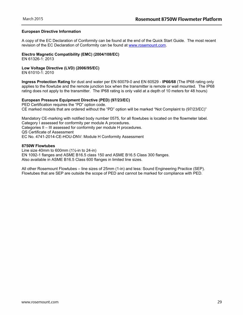
European Directive Information
A copy of the EC Declaration of Conformity can be found at the end of the Quick Start Guide. The most recent revision of the EC Declaration of Conformity can be found at www.rosemount.com. Electro Magnetic Compatibility (EMC) (2004/108/EC) EN 61326-1: 2013 Low Voltage Directive (LVD) (2006/95/EC) EN 61010-1: 2010 Ingress Protection Rating for dust and water per EN 60079-0 and EN 60529 - IP66/68 (The IP68 rating only applies to the flowtube and the remote junction box when the transmitter is remote or wall mounted. The IP68 rating does not apply to the transmitter. The IP68 rating is only valid at a depth of 10 meters for 48 hours) European Pressure Equipment Directive (PED) (97/23/EC) PED Certification requires the “PD” option code. CE marked models that are ordered without the “PD” option will be marked “Not Complaint to (97/23/EC)” Mandatory CE-marking with notified body number 0575, for all flowtubes is located on the flowmeter label. Category I assessed for conformity per module A procedures. Categories II – III assessed for conformity per module H procedures. QS Certificate of Assessment EC No. 4741-2014-CE-HOU-DNV: Module H Conformity Assessment 8750W Flowtubes Line size 40mm to 600mm (1½-in to 24-in) EN 1092-1 flanges and ASME B16.5 class 150 and ASME B16.5 Class 300 flanges. Also available in ASME B16.5 Class 600 flanges in limited line sizes. All other Rosemount Flowtubes – line sizes of 25mm (1-in) and less: Sound Engineering Practice (SEP). Flowtubes that are SEP are outside the scope of PED and cannot be marked for compliance with PED.
30
Rosemount 8750W Flowmeter Platform March 2015
www.rosemount.com
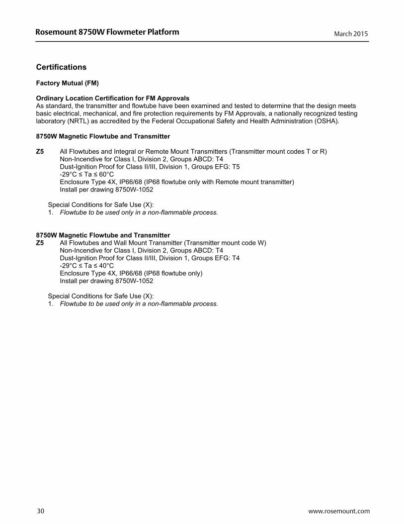
Certifications Factory Mutual (FM)
Ordinary Location Certification for FM Approvals As standard, the transmitter and flowtube have been examined and tested to determine that the design meets basic electrical, mechanical, and fire protection requirements by FM Approvals, a nationally recognized testing laboratory (NRTL) as accredited by the Federal Occupational Safety and Health Administration (OSHA). 8750W Magnetic Flowtube and Transmitter Z5 All Flowtubes and Integral or Remote Mount Transmitters (Transmitter mount codes T or R)
Non-Incendive for Class I, Division 2, Groups ABCD: T4 Dust-Ignition Proof for Class II/III, Division 1, Groups EFG: T5 -29°C Ta 60°C Enclosure Type 4X, IP66/68 (IP68 flowtube only with Remote mount transmitter) Install per drawing 8750W-1052
Special Conditions for Safe Use (X): 1. Flowtube to be used only in a non-flammable process.
8750W Magnetic Flowtube and Transmitter Z5 All Flowtubes and Wall Mount Transmitter (Transmitter mount code W)
Non-Incendive for Class I, Division 2, Groups ABCD: T4 Dust-Ignition Proof for Class II/III, Division 1, Groups EFG: T4 -29°C Ta 40°C Enclosure Type 4X, IP66/68 (IP68 flowtube only) Install per drawing 8750W-1052
Special Conditions for Safe Use (X): 1. Flowtube to be used only in a non-flammable process.

Rosemount 8750W Flowmeter PlatformMarch 2015
Figure 8. Rosemount 8750W Declaration of Conformity
31www.rosemount.com

Rosemount 8750W Flowmeter Platform March 2015
32 www.rosemount.com

Rosemount 8750W Flowmeter PlatformMarch 2015
Dimensional Drawings
Figure 9. Rosemount 8750W Field Mount Transmitter
A. 1/2”-14 NPT or M20 conduit entryB. LOI cover
C. 2-in. pipe bracketD. Ground lug
33www.rosemount.com
Rosemount 8750W Flowmeter Platform March 2015
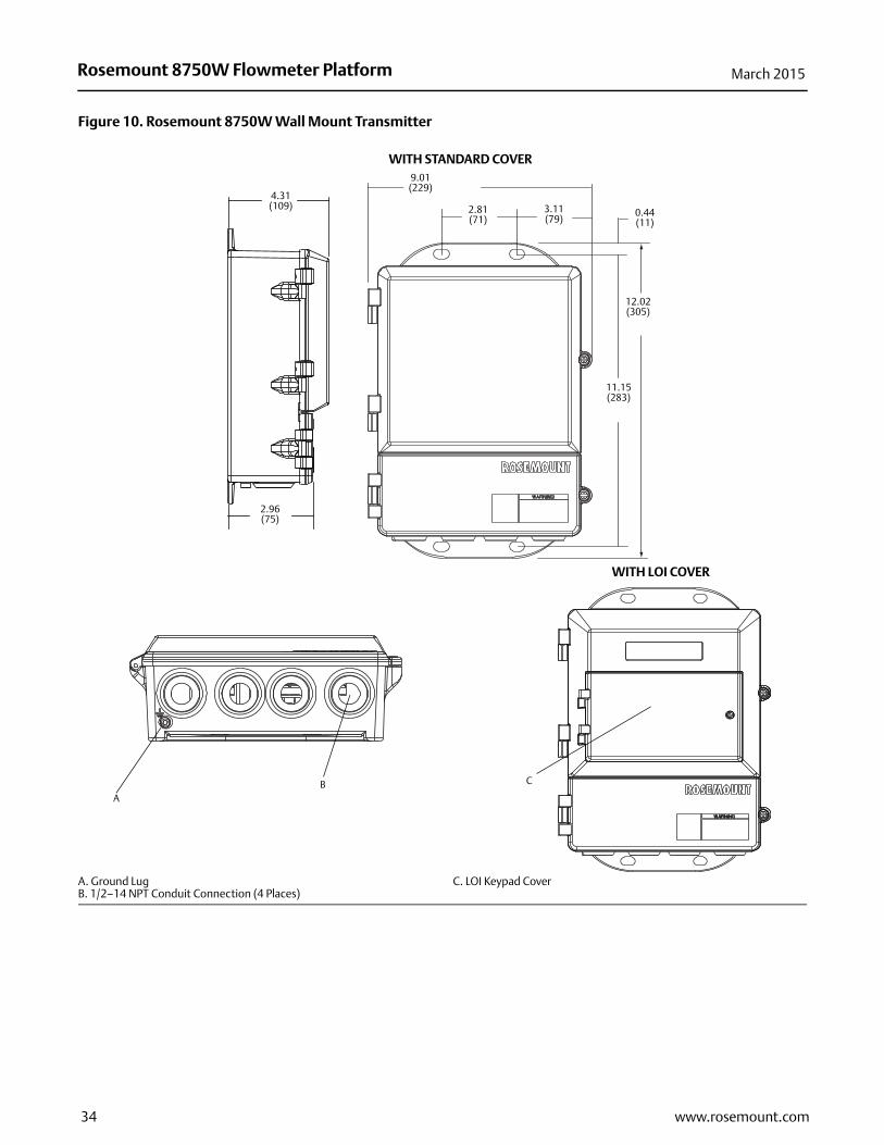
Figure 10. Rosemount 8750W Wall Mount Transmitter
A. Ground LugB. 1/2–14 NPT Conduit Connection (4 Places)
C. LOI Keypad Cover
4.31(109)
C
9.01(229)
11.15(283)
2.81(71)
3.11(79)
12.02(305)
0.44(11)
AB
WITH STANDARD COVER
2.96(75)
WITH LOI COVER
34 www.rosemount.com

Rosemount 8750W Flowmeter PlatformMarch 2015
Figure 11. Rosemount 8750W Raised Face Flanged Sensor 1/2-in. to 2.5-in. (15mm to 65mm)
Table 20. Rosemount 8750W Raised Face Flanged Sensor 1/2-in. to 2.5-in. (15mm to 65mm) Dimensions
Size, description
Overall lengthBody DIM “C”
DIM “D”Liner on
face DIM “J”
Flow tube weight
(lbs./kg)DIM “A”
PTFEDIM “A”
NeopreneDIM “A”
Poly0.5-in. (15 mm) ASME - 150, SO / RF 7.88 (200) 7.88 (200) 7.88 (200) 4.50 (114) 4.41 (112) 1.38 (35) 9 (4)
0.5-in. (15 mm) ASME - 300, SO / RF 7.88 (200) 7.88 (200) 7.88 (200) 4.50 (114) 4.41 (112) 1.38 (35) 10 (5)
0.5-in. (15 mm) EN 1092-1 - PN40, SO / RF 7.88 (200) 7.88 (200) 7.88 (200) 4.50 (114) 4.41 (112) 1.77 (45) 10 (5)
0.5-in. (15 mm) AS 2129 Table “D”, SO / RF 7.88 (200) 7.88 (200) 7.88 (200) 4.50 (114) 4.41 (112) 1.85 (47) 8 (4)
0.5-in. (15 mm) AS 2129 Table “E”, SO / RF 7.88 (200) 7.88 (200) 7.88 (200) 4.50 (114) 4.41 (112) 1.85 (47) 8 (4)
0.5-in. (15 mm) JIS B2220 - 10K, SO / RF 7.88 (200) 7.88 (200) 7.88 (200) 4.50 (114) 4.41 (112) 1.77 (45) 10 (5)
0.5-in. (15 mm) JIS B2220 - 20K, SO / RF 7.88 (200) 7.88 (200) 7.88 (200) 4.50 (114) 4.41 (112) 1.77 (45) 10 (5)
0.5-in. (15 mm) GB/T9119 PN40, SO / RF 7.88 (200) 7.88 (200) 7.88 (200) 4.50 (114) 4.41 (112) 1.77 (45) 10 (5)
1-in. (25 mm) ASME - 150, SO / RF 7.88 (200) 7.88 (200) 7.88 (200) 4.50 (114) 4.41 (112) 2.00 (51) 11 (5)
1-in. (25 mm) ASME - 300, SO / RF 7.88 (200) 7.88 (200) 7.88 (200) 4.50 (114) 4.41 (112) 2.00 (51) 14 (6)
1-in. (25 mm) EN 1092-1 - PN40, SO / RF 7.88 (200) 7.88 (200) 7.88 (200) 4.50 (114) 4.41 (112) 2.68 (68) 14 (6)
1-in. (25 mm) AS 2129 Table “D”, SO / RF 7.88 (200) 7.88 (200) 7.88 (200) 4.50 (114) 4.41 (112) 2.56 (65) 10 (5)
1-in. (25 mm) AS 2129 Table “E”, SO / RF 7.88 (200) 7.88 (200) 7.88 (200) 4.50 (114) 4.41 (112) 2.48 (63) 10 (5)
1 -in. (25 mm) JIS B2220 - 10K, SO / RF 7.88 (200) 7.88 (200) 7.88 (200) 4.50 (114) 4.41 (112) 2.64 (67) 13 (6)
1-in. (25 mm) JIS B2220 - 20K, SO / RF 7.88 (200) 7.88 (200) 7.88 (200) 4.50 (114) 4.41 (112) 2.64 (67) 14 (6)
1-in. (25 mm) GB/T9119 PN40, SO / RF 7.88 (200) 7.88 (200) 7.88 (200) 4.50 (114) 4.41 (112) 2.68 (68) 14 (6)
1.5-in. (40 mm) ASME - 150, SO / RF 7.87 (200) 7.80 (198) 7.87 (200) 5.21 (132) 4.82 (122) 2.88 (73) 15 (7)
1.5-in. (40 mm) ASME - 300, SO / RF 7.87 (200) 7.80 (198) 7.87 (200) 5.21 (132) 4.82 (122) 2.88 (73) 21 (9)
1.5-in. (40 mm) EN 1092-1 - PN40, SO / RF 7.87 (200) 7.80 (198) 7.87 (200) 5.21 (132) 4.82 (122) 3.46 (88) 19 (9)
1.5-in. (40 mm) AS 2129 Table “D”, SO / RF 7.87 (200) 7.80 (198) 7.87 (200) 5.21 (132) 4.82 (122) 3.07 (78) 12 (6)
1.5-in. (40 mm) AS 2129 Table “E”, SO / RF 7.87 (200) 7.80 (198) 7.87 (200) 5.21 (132) 4.82 (122) 3.07 (78) 13 (6)
1.5-in. (40 mm) JIS B2220 - 10K, SO / RF 7.87 (200) 7.80 (198) 7.87 (200) 5.21 (132) 4.82 (122) 3.19 (81) 16 (7)
1.5-in. (40 mm) JIS B2220 - 20K, SO / RF 7.87 (200) 7.80 (198) 7.87 (200) 5.21 (132) 4.82 (122) 3.19 (81) 17 (8)
1.5-in. (40 mm) GB/T9119 PN40, SO / RF 7.87 (200) 7.80 (198) 7.87 (200) 5.21 (132) 4.82 (122) 3.46 (88) 19 (9)
2-in. (50 mm) ASME - 150, SO / RF 7.87 (200) 7.80 (198) 7.87 (200) 5.21 (132) 4.82 (122) 3.62 (92) 20 (9)
2-in. (50 mm) ASME - 300, SO / RF 7.87 (200) 7.80 (198) 7.87 (200) 5.21 (132) 4.82 (122) 3.62 (92) 23 (11)
2-in. (50 mm) EN 1092-1 - PN40, SO / RF 7.87 (200) 7.80 (198) 7.87 (200) 5.21 (132) 4.82 (122) 4.02 (102) 23 (11)
35www.rosemount.com

Rosemount 8750W Flowmeter Platform March 2015
2-in. (50 mm) AS 2129 Table “D”, SO / RF 7.87 (200) 7.80 (198) 7.87 (200) 5.21 (132) 4.82 (122) 3.54 (90) 14 (6)
2-in. (50 mm) AS 2129 Table “E”, SO / RF 7.87 (200) 7.80 (198) 7.87 (200) 5.21 (132) 4.82 (122) 3.54 (90) 15 (7)
2-in. (50 mm) JIS B2220 - 10K, SO / RF 7.87 (200) 7.80 (198) 7.87 (200) 5.21 (132) 4.82 (122) 3.78 (96) 18 (8)
2-in. (50 mm) JIS B2220 - 20K, SO / RF 7.87 (200) 7.80 (198) 7.87 (200) 5.21 (132) 4.82 (122) 3.78 (96) 19 (9)
2-in. (50 mm) AS 4087 PN16, SO / RF 7.87 (200) 7.80 (198) 7.87 (200) 5.21 (132) 4.82 (122) 3.54 (90) 16 (7)
2-in. (50 mm) AS 4087 PN21, SO / RF 7.87 (200) 7.80 (198) 7.87 (200) 5.21 (132) 4.82 (122) 4.06 (103) 34 (16)
2-in. (50 mm) AS 4087 PN35, SO / RF 7.87 (200) 7.80 (198) 7.87 (200) 5.21 (132) 4.82 (122) 4.06 (103) 96 (44)
2-in. (50 mm) GB/T9119 PN40, SO / RF 7.87 (200) 7.80 (198) 7.87 (200) 5.21 (132) 4.82 (122) 4.02 (102) 23 (11)
2.5-in. (65 mm) ASME - 150, SO / RF 7.82 (199) 7.76 (197) N/A 6.31 (160) 5.37 (136) 4.12 (105) 27 (12)
2.5-in. (65 mm) ASME - 300, SO / RF 7.82 (199) 7.76 (197) N/A 6.31 (160) 5.37 (136) 4.12 (105) 32 (15)
2.5-in. (65 mm) EN 1092-1 - PN16, SO / RF 7.82 (199) 7.76 (197) N/A 6.31 (160) 5.37 (136) 4.80 (122) 27 (12)
2.5-in. (65 mm) EN 1092-1 - PN40, SO / RF 7.82 (199) 7.76 (197) N/A 6.31 (160) 5.37 (136) 4.80 (122) 31 (14)
2.5-in. (65 mm) AS 2129 Table “D”, SO / RF 7.82 (199) 7.76 (197) N/A 6.31 (160) 5.37 (136) 4.06 (103) 17 (8)
2.5-in. (65 mm) AS 2129 Table “E”, SO / RF 7.82 (199) 7.76 (197) N/A 6.31 (160) 5.37 (136) 4.06 (103) 19 (9)
2.5-in. (65 mm) JIS B2220 - 10K, SO / RF 7.82 (199) 7.76 (197) N/A 6.31 (160) 5.37 (136) 4.57 (116) 25 (11)
2.5-in. (65 mm) JIS B2220 - 20K, SO / RF 7.82 (199) 7.76 (197) N/A 6.31 (160) 5.37 (136) 4.57 (116) 26 (12)
2.5-in. (65 mm) AS 4087 PN16, SO / RF 7.82 (199) 7.76 (197) N/A 6.31 (160) 5.37 (136) 4.06 (103) 18 (8)
2.5-in. (65 mm) AS 4087 PN21, SO / RF 7.82 (199) 7.76 (197) N/A 6.31 (160) 5.37 (136) 4.80 (122) 24 (11)
2.5-in. (65 mm) AS 4087 PN35, SO / RF 7.82 (199) 7.76 (197) N/A 6.31 (160) 5.37 (136) 4.80 (122) 27 (12)
2.5-in. (65 mm) GB/T9119 PN40, SO / RF 7.82 (199) 7.76 (197) N/A 6.31 (160) 5.37 (136) 4.80 (122) 31 (14)
Table 20. Rosemount 8750W Raised Face Flanged Sensor 1/2-in. to 2.5-in. (15mm to 65mm) Dimensions
Size, description
Overall lengthBody DIM “C”
DIM “D”Liner on
face DIM “J”
Flow tube weight
(lbs./kg)DIM “A”
PTFEDIM “A”
NeopreneDIM “A”
Poly
36 www.rosemount.com
Rosemount 8750W Flowmeter PlatformMarch 2015
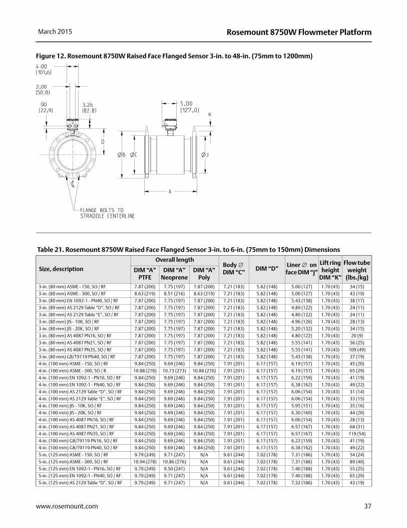
Figure 12. Rosemount 8750W Raised Face Flanged Sensor 3-in. to 48-in. (75mm to 1200mm)
Table 21. Rosemount 8750W Raised Face Flanged Sensor 3-in. to 6-in. (75mm to 150mm) Dimensions
Size, description
Overall lengthBody DIM “C”
DIM “D”Liner on face DIM “J”
Lift ring height
DIM “K”
Flow tube weight
(lbs./kg)DIM “A”
PTFEDIM “A”
NeopreneDIM “A”
Poly3-in. (80 mm) ASME - 150, SO / RF 7.87 (200) 7.75 (197) 7.87 (200) 7.21 (183) 5.82 (148) 5.00 (127) 1.70 (43) 34 (15)
3-in. (80 mm) ASME - 300, SO / RF 8.63 (219) 8.51 (216) 8.63 (219) 7.21 (183) 5.82 (148) 5.00 (127) 1.70 (43) 43 (19)
3-in. (80 mm) EN 1092-1 - PN40, SO / RF 7.87 (200) 7.75 (197) 7.87 (200) 7.21 (183) 5.82 (148) 5.43 (138) 1.70 (43) 38 (17)
3-in. (80 mm) AS 2129 Table “D”, SO / RF 7.87 (200) 7.75 (197) 7.87 (200) 7.21 (183) 5.82 (148) 4.80 (122) 1.70 (43) 24 (11)
3-in. (80 mm) AS 2129 Table “E”, SO / RF 7.87 (200) 7.75 (197) 7.87 (200) 7.21 (183) 5.82 (148) 4.80 (122) 1.70 (43) 24 (11)
3-in. (80 mm) JIS - 10K, SO / RF 7.87 (200) 7.75 (197) 7.87 (200) 7.21 (183) 5.82 (148) 4.96 (126) 1.70 (43) 28 (13)
3-in. (80 mm) JIS - 20K, SO / RF 7.87 (200) 7.75 (197) 7.87 (200) 7.21 (183) 5.82 (148) 5.20 (132) 1.70 (43) 34 (15)
3-in. (80 mm) AS 4087 PN16, SO / RF 7.87 (200) 7.75 (197) 7.87 (200) 7.21 (183) 5.82 (148) 4.80 (122) 1.70 (43) 20 (9)
3-in. (80 mm) AS 4087 PN21, SO / RF 7.87 (200) 7.75 (197) 7.87 (200) 7.21 (183) 5.82 (148) 5.55 (141) 1.70 (43) 56 (25)
3-in. (80 mm) AS 4087 PN35, SO / RF 7.87 (200) 7.75 (197) 7.87 (200) 7.21 (183) 5.82 (148) 5.55 (141) 1.70 (43) 109 (49)
3-in. (80 mm) GB/T9119 PN40, SO / RF 7.87 (200) 7.75 (197) 7.87 (200) 7.21 (183) 5.82 (148) 5.43 (138) 1.70 (43) 37 (19)
4-in. (100 mm) ASME - 150, SO / RF 9.84 (250) 9.69 (246) 9.84 (250) 7.91 (201) 6.17 (157) 6.19 (157) 1.70 (43) 45 (20)
4-in. (100 mm) ASME - 300, SO / R 10.88 (276) 10.73 (273) 10.88 (276) 7.91 (201) 6.17 (157) 6.19 (157) 1.70 (43) 65 (29)
4-in. (100 mm) EN 1092-1 - PN16, SO / RF 9.84 (250) 9.69 (246) 9.84 (250) 7.91 (201) 6.17 (157) 6.22 (159) 1.70 (43) 41 (19)
4-in. (100 mm) EN 1092-1 - PN40, SO / RF 9.84 (250) 9.69 (246) 9.84 (250) 7.91 (201) 6.17 (157) 6.38 (162) 1.70 (43) 49 (22)
4-in. (100 mm) AS 2129 Table “D”, SO / RF 9.84 (250) 9.69 (246) 9.84 (250) 7.91 (201) 6.17 (157) 6.06 (154) 1.70 (43) 31 (14)
4-in. (100 mm) AS 2129 Table “E”, SO / RF 9.84 (250) 9.69 (246) 9.84 (250) 7.91 (201) 6.17 (157) 6.06 (154) 1.70 (43) 33 (15)
4-in. (100 mm) JIS - 10K, SO / RF 9.84 (250) 9.69 (246) 9.84 (250) 7.91 (201) 6.17 (157) 5.95 (151) 1.70 (43) 35 (16)
4-in. (100 mm) JIS - 20K, SO / RF 9.84 (250) 9.69 (246) 9.84 (250) 7.91 (201) 6.17 (157) 6.30 (160) 1.70 (43) 44 (20)
4-in. (100 mm) AS 4087 PN16, SO / RF 9.84 (250) 9.69 (246) 9.84 (250) 7.91 (201) 6.17 (157) 6.06 (154) 1.70 (43) 28 (13)
4-in. (100 mm) AS 4087 PN21, SO / RF 9.84 (250) 9.69 (246) 9.84 (250) 7.91 (201) 6.17 (157) 6.57 (167) 1.70 (43) 68 (31)
4-in. (100 mm) AS 4087 PN35, SO / RF 9.84 (250) 9.69 (246) 9.84 (250) 7.91 (201) 6.17 (157) 6.57 (167) 1.70 (43) 119 (54)
4-in. (100 mm) GB/T9119 PN16, SO / RF 9.84 (250) 9.69 (246) 9.84 (250) 7.91 (201) 6.17 (157) 6.22 (159) 1.70 (43) 41 (19)
4-in. (100 mm) GB/T9119 PN40, SO / RF 9.84 (250) 9.69 (246) 9.84 (250) 7.91 (201) 6.17 (157) 6.38 (162) 1.70 (43) 49 (22)
5-in. (125 mm) ASME - 150, SO / RF 9.79 (249) 9.71 (247) N/A 9.61 (244) 7.02 (178) 7.31 (186) 1.70 (43) 54 (24)
5-in. (125 mm) ASME - 300, SO / RF 10.94 (278) 10.86 (276) N/A 9.61 (244) 7.02 (178) 7.31 (186) 1.70 (43) 89 (40)
5-in. (125 mm) EN 1092-1 - PN16, SO / RF 9.79 (249) 9.50 (241) N/A 9.61 (244) 7.02 (178) 7.40 (188) 1.70 (43) 55 (25)
5-in. (125 mm) EN 1092-1 - PN40, SO / RF 9.79 (249) 9.71 (247) N/A 9.61 (244) 7.02 (178) 7.40 (188) 1.70 (43) 65 (29)
5-in. (125 mm) AS 2129 Table “D”, SO / RF 9.79 (249) 9.71 (247) N/A 9.61 (244) 7.02 (178) 7.32 (186) 1.70 (43) 43 (19)
37www.rosemount.com
Rosemount 8750W Flowmeter Platform March 2015
5-in. (125 mm) AS 2129 Table “E”, SO / RF 9.79 (249) 9.71 (247) N/A 9.61 (244) 7.02 (178) 7.32 (186) 1.70 (43) 44 (20)
5-in. (125 mm) JIS - 10K, SO / RF 9.79 (249) 9.71 (247) N/A 9.61 (244) 7.02 (178) 7.17 (182) 1.70 (43) 49 (22)
5-in. (125 mm) JIS - 20K, SO / RF 9.79 (249) 9.71 (247) N/A 9.61 (244) 7.02 (178) 7.68 (195) 1.70 (43) 64 (29)
5-in. (125 mm) GB/T9119 PN16, SO / RF 9.79 (249) 9.50 (241) N/A 9.61 (244) 7.02 (178) 7.40 (188) 1.70 (43) 51 (23)
5-in. (125 mm) GB/T9119 PN40, SO / RF 9.79 (249) 9.71 (247) N/A 9.61 (244) 7.02 (178) 7.40 (188) 1.70 (43) 60 (27)
6-in. (150 mm) ASME - 150, SO / RF 11.81 (300) 11.61 (295) 11.73 (298) 9.98 (253) 7.30 (185) 8.50 (216) 1.70 (43) 68 (31)
6-in. (150 mm) ASME - 300, SO / RF 13.06 (302) 12.88 (327) 13.00 (330) 9.98 (253) 7.30 (185) 8.50 (216) 1.70 (43) 117 (53)
6-in. (150 mm) EN 1092-1 - PN16, SO / RF 11.81 (300) 11.61 (295) 11.73 (298) 9.98 (253) 7.30 (185) 8.35 (212) 1.70 (43) 67 (31)
6-in. (150 mm) EN 1092-1 - PN40, SO / RF 13.06 (302) 12.88 (327) 13.00 (330) 9.98 (253) 7.30 (185) 8.58 (218) 1.70 (43) 95 (43)
6-in. (150 mm) AS 2129 Table “D”, SO / RF 11.81 (300) 11.61 (295) 11.73 (298) 9.98 (253) 7.30 (185) 8.31 (211) 1.70 (43) 52 (24)
6-in. (150 mm) AS 2129 Table “E”, SO / RF 11.81 (300) 11.61 (295) 11.73 (298) 9.98 (253) 7.30 (185) 8.15 (207) 1.70 (43) 57 (26)
6-in. (150 mm) JIS - 10K, SO / RF 11.81 (300) 11.61 (295) 11.73 (298) 9.98 (253) 7.30 (185) 8.35 (212) 1.70 (43) 64 (29)
6-in. (150 mm) JIS - 20K, SO / RF 11.81 (300) 11.61 (295) 11.73 (298) 9.98 (253) 7.30 (185) 9.06 (230) 1.70 (43) 82 (37)
6-in. (150 mm) AS 4087 PN16, SO / RF 11.81 (300) 11.61 (295) 11.73 (298) 9.98 (253) 7.30 (185) 8.31 (211) 1.70 (43) 46 (21)
6-in. (150 mm) AS 4087 PN21, SO / RF 11.81 (300) 11.61 (295) 11.73 (298) 9.98 (253) 7.30 (185) 9.13 (232) 1.70 (43) 98 (45)
6-in. (150 mm) AS 4087 PN35, SO / RF 11.81 (300) 11.61 (295) 11.73 (298) 9.98 (253) 7.30 (185) 9.13 (232) 1.70 (43) 186 (84)
6-in. (150 mm) GB/T9119 PN16, SO / RF 11.81 (300) 11.61 (295) 11.73 (298) 9.98 (253) 7.30 (185) 8.35 (212) 1.70 (43) 64 (29)
6-in. (150 mm) GB/T9119 PN40, SO / RF 13.06 (302) 12.88 (327) 13.00 (330) 9.98 (253) 7.30 (185) 8.58 (218) 1.70 (43) 94 (43)
Table 21. Rosemount 8750W Raised Face Flanged Sensor 3-in. to 6-in. (75mm to 150mm) Dimensions
Size, description
Overall lengthBody DIM “C”
DIM “D”Liner on face DIM “J”
Lift ring height
DIM “K”
Flow tube weight
(lbs./kg)DIM “A”
PTFEDIM “A”
NeopreneDIM “A”
Poly
Table 22. Rosemount 8750W Raised Face Flanged Sensor 8-in. to 12-in. (200mm to 300mm) Dimensions
Size, description
Overall lengthBody DIM “C”
DIM “D”Liner on
face DIM “J”
Lift ring height
DIM “K”
Flow tube weight
(lbs./kg)DIM “A”
PTFEDIM “A”
NeopreneDIM “A”
Poly8-in. (200 mm) ASME - 150, SO / RF 13.78 (350) 13.53 (344) 13.65 (347) 11.92 (303) 8.27 (210) 10.62 (270) 1.70 (43) 105 (48)
8-in. (200 mm) ASME - 300, SO / RF 15.60 (396) 15.42 (392) 15.54 (395) 11.92 (303) 8.27 (210) 10.62 (270) 1.70 (43) 183 (83)
8-in. (200 mm) EN 1092-1 - PN10, SO / RF 13.78 (350) 13.53 (344) 13.65 (347) 11.92 (303) 8.27 (210) 10.55 (268) 1.70 (43) 97 (44)
8-in. (200 mm) EN 1092-1 - PN16, SO / RF 13.78 (350) 13.53 (344) 13.65 (347) 11.92 (303) 8.27 (210) 10.55 (268) 1.70 (43) 96 (43)
8-in. (200 mm) EN 1092-1 - PN25, SO / RF 13.78 (350) 13.53 (344) 13.65 (347) 11.92 (303) 8.27 (210) 10.94 (278) 1.70 (43) 120 (54)
8-in. (200 mm) EN 1092-1 - PN40, SO / RF 15.60 (396) 15.42 (392) 15.54 (395) 11.92 (303) 8.27 (210) 11.22 (285) 1.70 (43) 158 (72)
8-in. (200 mm) AS 2129 Table “D”, SO / RF 13.78 (350) 13.53 (344) 13.65 (347) 11.92 (303) 8.27 (210) 10.55 (268) 1.70 (43) 77 (35)
8-in. (200 mm) AS 2129 Table “E”, SO / RF 13.78 (350) 13.53 (344) 13.65 (347) 11.92 (303) 8.27 (210) 10.39 (264) 1.70 (43) 86 (39)
8-in. (200 mm) JIS - 10K, SO / RF 13.78 (350) 13.53 (344) 13.65 (347) 11.92 (303) 8.27 (210) 10.32 (262) 1.70 (43) 81 (37)
8-in. (200 mm) JIS - 20K, SO / RF 15.60 (396) 15.42 (392) 15.54 (395) 11.92 (303) 8.27 (210) 10.83 (275) 1.70 (43) 134 (61)
8-in. (200 mm) AS 4087 PN16, SO / RF 13.78 (350) 13.53 (344) 13.65 (347) 11.92 (303) 8.27 (210) 10.55 (268) 1.70 (43) 73 (32)
8-in. (200 mm) AS 4087 PN21, SO / RF 13.78 (350) 13.53 (344) 13.65 (347) 11.92 (303) 8.27 (210) 11.65 (296) 1.70 (43) 136 (62)
8-in. (200 mm) AS 4087 PN35, SO / RF 15.60 (396) 15.42 (392) 15.54 (395) 11.92 (303) 8.27 (210) 10.24 (260) 1.70 (43) 241 (109)
8-in. (200 mm) GB/T9119 PN10, SO / RF 13.78 (350) 13.53 (344) 13.65 (347) 11.92 (303) 8.27 (210) 10.55 (268) 1.70 (43) 96 (43)
8-in. (200 mm) GB/T9119 PN16, SO / RF 13.78 (350) 13.53 (344) 13.65 (347) 11.92 (303) 8.27 (210) 10.55 (268) 1.70 (43) 95 (43)
8-in. (200 mm) GB/T9119 PN40, SO / RF 15.60 (396) 15.42 (392) 15.54 (395) 11.92 (303) 8.27 (210) 11.22 (285) 1.70 (43) 154 (70)
10-in. (250 mm) ASME - 150, SO / RF 17.98 (457) 17.61 (447) 17.73 (450) 13.12 (333) 8.91 (226) 12.75 (324) 2.00 (51) 138 (63)
10-in. (250 mm) ASME - 300, SO / RF 17.88 (454) 17.61 (447) 17.73 (450) 13.12 (333) 8.91 (226) 12.75 (324) 2.00 (51) 247 (112)
10-in. (250 mm) EN 1092-1 - PN10, SO / RF 17.98 (457) 17.61 (447) 17.73 (450) 13.12 (333) 8.91 (226) 12.60 (320) 2.00 (51) 122 (55)
10-in. (250 mm) EN 1092-1 - PN16, SO / RF 17.98 (457) 17.61 (447) 17.73 (450) 13.12 (333) 8.91 (226) 12.60 (320) 2.00 (51) 126 (57)
10-in. (250 mm) EN 1092-1 - PN25, SO / RF 17.98 (457) 17.61 (447) 17.73 (450) 13.12 (333) 8.91 (226) 13.19 (335) 2.00 (51) 158 (72)
10-in. (250 mm) EN 1092-1 - PN40, SO / RF 17.88 (454) 17.61 (447) 17.73 (450) 13.12 (333) 8.91 (226) 13.58 (345) 2.00 (51) 221 (100)
10-in. (250 mm) AS 2129 Table “D”, SO / RF 17.98 (457) 17.61 (447) 17.73 (450) 13.12 (333) 8.91 (226) 12.91 (328) 2.00 (51) 112 (51)
10-in. (250 mm) AS 2129 Table “E”, SO / RF 17.98 (457) 17.61 (447) 17.73 (450) 13.12 (333) 8.91 (226) 12.91 (328) 2.00 (51) 127 (57)
10-in. (250 mm) JIS B2220 - 10K, SO / RF 17.98 (457) 17.61 (447) 17.73 (450) 13.12 (333) 8.91 (226) 12.76 (324) 1.70 (43) 118 (53)
10-in. (250 mm) AS 4087 PN16, SO / RF 17.98 (457) 17.61 (447) 17.73 (450) 13.12 (333) 8.91 (226) 12.91 (328) 2.00 (51) 168 (76)
10-in. (250 mm) AS 4087 PN21, SO / RF 17.98 (457) 17.61 (447) 17.73 (450) 13.12 (333) 8.91 (226) 13.74 (349) 2.00 (51) 258 (117)
10-in. (250 mm) AS 4087 PN35, SO / RF 17.88 (454) 17.61 (447) 17.73 (450) 13.12 (333) 8.91 (226) 12.24 (311) 2.00 (51) 333 (151)
10-in. (250 mm) GB/T 9119 PN10, SO / RF 17.98 (457) 17.61 (447) 17.73 (450) 13.12 (333) 8.91 (226) 12.60 (320) 2.00 (51) 105 (48)
10-in. (250 mm) GB/T 9119 PN16, SO / RF 17.98 (457) 17.61 (447) 17.73 (450) 13.12 (333) 8.91 (226) 12.60 (320) 2.00 (51) 117 (53)
10-in. (250 mm) GB/T 9119 PN40, SO / RF 17.88 (454) 17.61 (447) 17.73 (450) 13.12 (333) 8.91 (226) 13.58 (345) 2.00 (51) 213 (97)
12-in. (300 mm) ASME - 150, SO / RF 19.91 (506) 19.58 (497) 19.70 (500) 15.12 (384) 9.91 (252) 15.00 (381) 2.00 (51) 238 (108)
38 www.rosemount.com
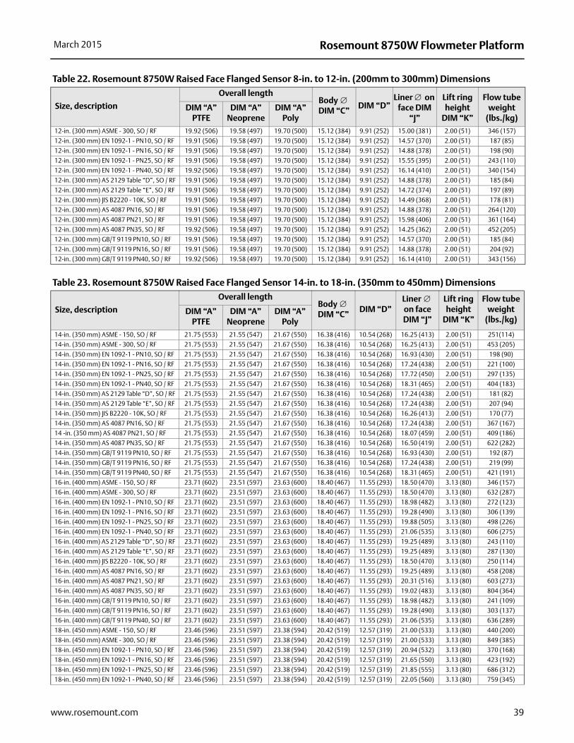
Rosemount 8750W Flowmeter PlatformMarch 2015
12-in. (300 mm) ASME - 300, SO / RF 19.92 (506) 19.58 (497) 19.70 (500) 15.12 (384) 9.91 (252) 15.00 (381) 2.00 (51) 346 (157)
12-in. (300 mm) EN 1092-1 - PN10, SO / RF 19.91 (506) 19.58 (497) 19.70 (500) 15.12 (384) 9.91 (252) 14.57 (370) 2.00 (51) 187 (85)
12-in. (300 mm) EN 1092-1 - PN16, SO / RF 19.91 (506) 19.58 (497) 19.70 (500) 15.12 (384) 9.91 (252) 14.88 (378) 2.00 (51) 198 (90)
12-in. (300 mm) EN 1092-1 - PN25, SO / RF 19.91 (506) 19.58 (497) 19.70 (500) 15.12 (384) 9.91 (252) 15.55 (395) 2.00 (51) 243 (110)
12-in. (300 mm) EN 1092-1 - PN40, SO / RF 19.92 (506) 19.58 (497) 19.70 (500) 15.12 (384) 9.91 (252) 16.14 (410) 2.00 (51) 340 (154)
12-in. (300 mm) AS 2129 Table “D”, SO / RF 19.91 (506) 19.58 (497) 19.70 (500) 15.12 (384) 9.91 (252) 14.88 (378) 2.00 (51) 185 (84)
12-in. (300 mm) AS 2129 Table “E”, SO / RF 19.91 (506) 19.58 (497) 19.70 (500) 15.12 (384) 9.91 (252) 14.72 (374) 2.00 (51) 197 (89)
12-in. (300 mm) JIS B2220 - 10K, SO / RF 19.91 (506) 19.58 (497) 19.70 (500) 15.12 (384) 9.91 (252) 14.49 (368) 2.00 (51) 178 (81)
12-in. (300 mm) AS 4087 PN16, SO / RF 19.91 (506) 19.58 (497) 19.70 (500) 15.12 (384) 9.91 (252) 14.88 (378) 2.00 (51) 264 (120)
12-in. (300 mm) AS 4087 PN21, SO / RF 19.91 (506) 19.58 (497) 19.70 (500) 15.12 (384) 9.91 (252) 15.98 (406) 2.00 (51) 361 (164)
12-in. (300 mm) AS 4087 PN35, SO / RF 19.92 (506) 19.58 (497) 19.70 (500) 15.12 (384) 9.91 (252) 14.25 (362) 2.00 (51) 452 (205)
12-in. (300 mm) GB/T 9119 PN10, SO / RF 19.91 (506) 19.58 (497) 19.70 (500) 15.12 (384) 9.91 (252) 14.57 (370) 2.00 (51) 185 (84)
12-in. (300 mm) GB/T 9119 PN16, SO / RF 19.91 (506) 19.58 (497) 19.70 (500) 15.12 (384) 9.91 (252) 14.88 (378) 2.00 (51) 204 (92)
12-in. (300 mm) GB/T 9119 PN40, SO / RF 19.92 (506) 19.58 (497) 19.70 (500) 15.12 (384) 9.91 (252) 16.14 (410) 2.00 (51) 343 (156)
Table 22. Rosemount 8750W Raised Face Flanged Sensor 8-in. to 12-in. (200mm to 300mm) Dimensions
Size, description
Overall lengthBody DIM “C”
DIM “D”Liner on
face DIM “J”
Lift ring height
DIM “K”
Flow tube weight
(lbs./kg)DIM “A”
PTFEDIM “A”
NeopreneDIM “A”
Poly
Table 23. Rosemount 8750W Raised Face Flanged Sensor 14-in. to 18-in. (350mm to 450mm) Dimensions
Size, description
Overall lengthBody DIM “C”
DIM “D”Liner on face DIM “J”
Lift ring height
DIM “K”
Flow tube weight
(lbs./kg)DIM “A”
PTFEDIM “A”
NeopreneDIM “A”
Poly14-in. (350 mm) ASME - 150, SO / RF 21.75 (553) 21.55 (547) 21.67 (550) 16.38 (416) 10.54 (268) 16.25 (413) 2.00 (51) 251(114)
14-in. (350 mm) ASME - 300, SO / RF 21.75 (553) 21.55 (547) 21.67 (550) 16.38 (416) 10.54 (268) 16.25 (413) 2.00 (51) 453 (205)
14-in. (350 mm) EN 1092-1 - PN10, SO / RF 21.75 (553) 21.55 (547) 21.67 (550) 16.38 (416) 10.54 (268) 16.93 (430) 2.00 (51) 198 (90)
14-in. (350 mm) EN 1092-1 - PN16, SO / RF 21.75 (553) 21.55 (547) 21.67 (550) 16.38 (416) 10.54 (268) 17.24 (438) 2.00 (51) 221 (100)
14-in. (350 mm) EN 1092-1 - PN25, SO / RF 21.75 (553) 21.55 (547) 21.67 (550) 16.38 (416) 10.54 (268) 17.72 (450) 2.00 (51) 297 (135)
14-in. (350 mm) EN 1092-1 - PN40, SO / RF 21.75 (553) 21.55 (547) 21.67 (550) 16.38 (416) 10.54 (268) 18.31 (465) 2.00 (51) 404 (183)
14-in. (350 mm) AS 2129 Table “D”, SO / RF 21.75 (553) 21.55 (547) 21.67 (550) 16.38 (416) 10.54 (268) 17.24 (438) 2.00 (51) 181 (82)
14-in. (350 mm) AS 2129 Table “E”, SO / RF 21.75 (553) 21.55 (547) 21.67 (550) 16.38 (416) 10.54 (268) 17.24 (438) 2.00 (51) 207 (94)
14-in. (350 mm) JIS B2220 - 10K, SO / RF 21.75 (553) 21.55 (547) 21.67 (550) 16.38 (416) 10.54 (268) 16.26 (413) 2.00 (51) 170 (77)
14-in. (350 mm) AS 4087 PN16, SO / RF 21.75 (553) 21.55 (547) 21.67 (550) 16.38 (416) 10.54 (268) 17.24 (438) 2.00 (51) 367 (167)
14 -in. (350 mm) AS 4087 PN21, SO / RF 21.75 (553) 21.55 (547) 21.67 (550) 16.38 (416) 10.54 (268) 18.07 (459) 2.00 (51) 409 (186)
14-in. (350 mm) AS 4087 PN35, SO / RF 21.75 (553) 21.55 (547) 21.67 (550) 16.38 (416) 10.54 (268) 16.50 (419) 2.00 (51) 622 (282)
14-in. (350 mm) GB/T 9119 PN10, SO / RF 21.75 (553) 21.55 (547) 21.67 (550) 16.38 (416) 10.54 (268) 16.93 (430) 2.00 (51) 192 (87)
14-in. (350 mm) GB/T 9119 PN16, SO / RF 21.75 (553) 21.55 (547) 21.67 (550) 16.38 (416) 10.54 (268) 17.24 (438) 2.00 (51) 219 (99)
14-in. (350 mm) GB/T 9119 PN40, SO / RF 21.75 (553) 21.55 (547) 21.67 (550) 16.38 (416) 10.54 (268) 18.31 (465) 2.00 (51) 421 (191)
16-in. (400 mm) ASME - 150, SO / RF 23.71 (602) 23.51 (597) 23.63 (600) 18.40 (467) 11.55 (293) 18.50 (470) 3.13 (80) 346 (157)
16-in. (400 mm) ASME - 300, SO / RF 23.71 (602) 23.51 (597) 23.63 (600) 18.40 (467) 11.55 (293) 18.50 (470) 3.13 (80) 632 (287)
16-in. (400 mm) EN 1092-1 - PN10, SO / RF 23.71 (602) 23.51 (597) 23.63 (600) 18.40 (467) 11.55 (293) 18.98 (482) 3.13 (80) 272 (123)
16-in. (400 mm) EN 1092-1 - PN16, SO / RF 23.71 (602) 23.51 (597) 23.63 (600) 18.40 (467) 11.55 (293) 19.28 (490) 3.13 (80) 306 (139)
16-in. (400 mm) EN 1092-1 - PN25, SO / RF 23.71 (602) 23.51 (597) 23.63 (600) 18.40 (467) 11.55 (293) 19.88 (505) 3.13 (80) 498 (226)
16-in. (400 mm) EN 1092-1 - PN40, SO / RF 23.71 (602) 23.51 (597) 23.63 (600) 18.40 (467) 11.55 (293) 21.06 (535) 3.13 (80) 606 (275)
16-in. (400 mm) AS 2129 Table “D”, SO / RF 23.71 (602) 23.51 (597) 23.63 (600) 18.40 (467) 11.55 (293) 19.25 (489) 3.13 (80) 243 (110)
16-in. (400 mm) AS 2129 Table “E”, SO / RF 23.71 (602) 23.51 (597) 23.63 (600) 18.40 (467) 11.55 (293) 19.25 (489) 3.13 (80) 287 (130)
16-in. (400 mm) JIS B2220 - 10K, SO / RF 23.71 (602) 23.51 (597) 23.63 (600) 18.40 (467) 11.55 (293) 18.50 (470) 3.13 (80) 250 (114)
16-in. (400 mm) AS 4087 PN16, SO / RF 23.71 (602) 23.51 (597) 23.63 (600) 18.40 (467) 11.55 (293) 19.25 (489) 3.13 (80) 458 (208)
16-in. (400 mm) AS 4087 PN21, SO / RF 23.71 (602) 23.51 (597) 23.63 (600) 18.40 (467) 11.55 (293) 20.31 (516) 3.13 (80) 603 (273)
16-in. (400 mm) AS 4087 PN35, SO / RF 23.71 (602) 23.51 (597) 23.63 (600) 18.40 (467) 11.55 (293) 19.02 (483) 3.13 (80) 804 (364)
16-in. (400 mm) GB/T 9119 PN10, SO / RF 23.71 (602) 23.51 (597) 23.63 (600) 18.40 (467) 11.55 (293) 18.98 (482) 3.13 (80) 241 (109)
16-in. (400 mm) GB/T 9119 PN16, SO / RF 23.71 (602) 23.51 (597) 23.63 (600) 18.40 (467) 11.55 (293) 19.28 (490) 3.13 (80) 303 (137)
16-in. (400 mm) GB/T 9119 PN40, SO / RF 23.71 (602) 23.51 (597) 23.63 (600) 18.40 (467) 11.55 (293) 21.06 (535) 3.13 (80) 636 (289)
18-in. (450 mm) ASME - 150, SO / RF 23.46 (596) 23.51 (597) 23.38 (594) 20.42 (519) 12.57 (319) 21.00 (533) 3.13 (80) 440 (200)
18-in. (450 mm) ASME - 300, SO / RF 23.46 (596) 23.51 (597) 23.38 (594) 20.42 (519) 12.57 (319) 21.00 (533) 3.13 (80) 849 (385)
18-in. (450 mm) EN 1092-1 - PN10, SO / RF 23.46 (596) 23.51 (597) 23.38 (594) 20.42 (519) 12.57 (319) 20.94 (532) 3.13 (80) 370 (168)
18-in. (450 mm) EN 1092-1 - PN16, SO / RF 23.46 (596) 23.51 (597) 23.38 (594) 20.42 (519) 12.57 (319) 21.65 (550) 3.13 (80) 423 (192)
18-in. (450 mm) EN 1092-1 - PN25, SO / RF 23.46 (596) 23.51 (597) 23.38 (594) 20.42 (519) 12.57 (319) 21.85 (555) 3.13 (80) 686 (312)
18-in. (450 mm) EN 1092-1 - PN40, SO / RF 23.46 (596) 23.51 (597) 23.38 (594) 20.42 (519) 12.57 (319) 22.05 (560) 3.13 (80) 759 (345)
39www.rosemount.com
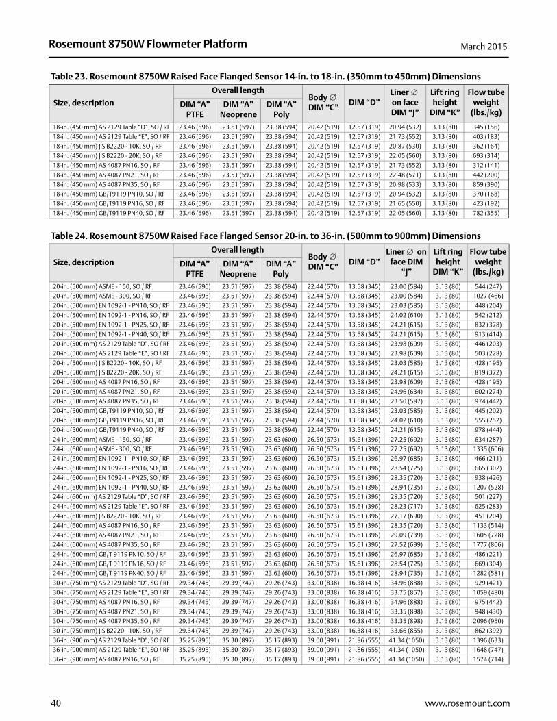
Rosemount 8750W Flowmeter Platform March 2015
18-in. (450 mm) AS 2129 Table “D”, SO / RF 23.46 (596) 23.51 (597) 23.38 (594) 20.42 (519) 12.57 (319) 20.94 (532) 3.13 (80) 345 (156)
18-in. (450 mm) AS 2129 Table “E”, SO / RF 23.46 (596) 23.51 (597) 23.38 (594) 20.42 (519) 12.57 (319) 21.73 (552) 3.13 (80) 403 (183)
18-in. (450 mm) JIS B2220 - 10K, SO / RF 23.46 (596) 23.51 (597) 23.38 (594) 20.42 (519) 12.57 (319) 20.87 (530) 3.13 (80) 362 (164)
18-in. (450 mm) JIS B2220 - 20K, SO / RF 23.46 (596) 23.51 (597) 23.38 (594) 20.42 (519) 12.57 (319) 22.05 (560) 3.13 (80) 693 (314)
18-in. (450 mm) AS 4087 PN16, SO / RF 23.46 (596) 23.51 (597) 23.38 (594) 20.42 (519) 12.57 (319) 21.73 (552) 3.13 (80) 312 (141)
18-in. (450 mm) AS 4087 PN21, SO / RF 23.46 (596) 23.51 (597) 23.38 (594) 20.42 (519) 12.57 (319) 22.48 (571) 3.13 (80) 442 (200)
18-in. (450 mm) AS 4087 PN35, SO / RF 23.46 (596) 23.51 (597) 23.38 (594) 20.42 (519) 12.57 (319) 20.98 (533) 3.13 (80) 859 (390)
18-in. (450 mm) GB/T9119 PN10, SO / RF 23.46 (596) 23.51 (597) 23.38 (594) 20.42 (519) 12.57 (319) 20.94 (532) 3.13 (80) 370 (168)
18-in. (450 mm) GB/T9119 PN16, SO / RF 23.46 (596) 23.51 (597) 23.38 (594) 20.42 (519) 12.57 (319) 21.65 (550) 3.13 (80) 423 (192)
18-in. (450 mm) GB/T9119 PN40, SO / RF 23.46 (596) 23.51 (597) 23.38 (594) 20.42 (519) 12.57 (319) 22.05 (560) 3.13 (80) 782 (355)
Table 23. Rosemount 8750W Raised Face Flanged Sensor 14-in. to 18-in. (350mm to 450mm) Dimensions
Size, description
Overall lengthBody DIM “C”
DIM “D”Liner on face DIM “J”
Lift ring height
DIM “K”
Flow tube weight
(lbs./kg)DIM “A”
PTFEDIM “A”
NeopreneDIM “A”
Poly
Table 24. Rosemount 8750W Raised Face Flanged Sensor 20-in. to 36-in. (500mm to 900mm) Dimensions
Size, description
Overall lengthBody DIM “C”
DIM “D”Liner on
face DIM “J”
Lift ring height
DIM “K”
Flow tube weight
(lbs./kg)DIM “A”
PTFEDIM “A”
NeopreneDIM “A”
Poly20-in. (500 mm) ASME - 150, SO / RF 23.46 (596) 23.51 (597) 23.38 (594) 22.44 (570) 13.58 (345) 23.00 (584) 3.13 (80) 544 (247)
20-in. (500 mm) ASME - 300, SO / RF 23.46 (596) 23.51 (597) 23.38 (594) 22.44 (570) 13.58 (345) 23.00 (584) 3.13 (80) 1027 (466)
20-in. (500 mm) EN 1092-1 - PN10, SO / RF 23.46 (596) 23.51 (597) 23.38 (594) 22.44 (570) 13.58 (345) 23.03 (585) 3.13 (80) 448 (204)
20-in. (500 mm) EN 1092-1 - PN16, SO / RF 23.46 (596) 23.51 (597) 23.38 (594) 22.44 (570) 13.58 (345) 24.02 (610) 3.13 (80) 542 (212)
20-in. (500 mm) EN 1092-1 - PN25, SO / RF 23.46 (596) 23.51 (597) 23.38 (594) 22.44 (570) 13.58 (345) 24.21 (615) 3.13 (80) 832 (378)
20-in. (500 mm) EN 1092-1 - PN40, SO / RF 23.46 (596) 23.51 (597) 23.38 (594) 22.44 (570) 13.58 (345) 24.21 (615) 3.13 (80) 913 (414)
20-in. (500 mm) AS 2129 Table “D”, SO / RF 23.46 (596) 23.51 (597) 23.38 (594) 22.44 (570) 13.58 (345) 23.98 (609) 3.13 (80) 446 (203)
20-in. (500 mm) AS 2129 Table “E”, SO / RF 23.46 (596) 23.51 (597) 23.38 (594) 22.44 (570) 13.58 (345) 23.98 (609) 3.13 (80) 503 (228)
20-in. (500 mm) JIS B2220 - 10K, SO / RF 23.46 (596) 23.51 (597) 23.38 (594) 22.44 (570) 13.58 (345) 23.03 (585) 3.13 (80) 428 (195)
20-in. (500 mm) JIS B2220 - 20K, SO / RF 23.46 (596) 23.51 (597) 23.38 (594) 22.44 (570) 13.58 (345) 24.21 (615) 3.13 (80) 819 (372)
20-in. (500 mm) AS 4087 PN16, SO / RF 23.46 (596) 23.51 (597) 23.38 (594) 22.44 (570) 13.58 (345) 23.98 (609) 3.13 (80) 428 (195)
20-in. (500 mm) AS 4087 PN21, SO / RF 23.46 (596) 23.51 (597) 23.38 (594) 22.44 (570) 13.58 (345) 24.96 (634) 3.13 (80) 602 (274)
20-in. (500 mm) AS 4087 PN35, SO / RF 23.46 (596) 23.51 (597) 23.38 (594) 22.44 (570) 13.58 (345) 23.50 (587) 3.13 (80) 974 (442)
20-in. (500 mm) GB/T9119 PN10, SO / RF 23.46 (596) 23.51 (597) 23.38 (594) 22.44 (570) 13.58 (345) 23.03 (585) 3.13 (80) 445 (202)
20-in. (500 mm) GB/T9119 PN16, SO / RF 23.46 (596) 23.51 (597) 23.38 (594) 22.44 (570) 13.58 (345) 24.02 (610) 3.13 (80) 555 (252)
20-in. (500 mm) GB/T9119 PN40, SO / RF 23.46 (596) 23.51 (597) 23.38 (594) 22.44 (570) 13.58 (345) 24.21 (615) 3.13 (80) 978 (444)
24-in. (600 mm) ASME - 150, SO / RF 23.46 (596) 23.51 (597) 23.63 (600) 26.50 (673) 15.61 (396) 27.25 (692) 3.13 (80) 634 (287)
24-in. (600 mm) ASME - 300, SO / RF 23.46 (596) 23.51 (597) 23.63 (600) 26.50 (673) 15.61 (396) 27.25 (692) 3.13 (80) 1335 (606)
24-in. (600 mm) EN 1092-1 - PN10, SO / RF 23.46 (596) 23.51 (597) 23.63 (600) 26.50 (673) 15.61 (396) 26.97 (685) 3.13 (80) 466 (211)
24-in. (600 mm) EN 1092-1 - PN16, SO / RF 23.46 (596) 23.51 (597) 23.63 (600) 26.50 (673) 15.61 (396) 28.54 (725) 3.13 (80) 665 (302)
24-in. (600 mm) EN 1092-1 - PN25, SO / RF 23.46 (596) 23.51 (597) 23.63 (600) 26.50 (673) 15.61 (396) 28.35 (720) 3.13 (80) 938 (426)
24-in. (600 mm) EN 1092-1 - PN40, SO / RF 23.46 (596) 23.51 (597) 23.63 (600) 26.50 (673) 15.61 (396) 28.94 (735) 3.13 (80) 1207 (528)
24-in. (600 mm) AS 2129 Table “D”, SO / RF 23.46 (596) 23.51 (597) 23.63 (600) 26.50 (673) 15.61 (396) 28.35 (720) 3.13 (80) 501 (227)
24-in. (600 mm) AS 2129 Table “E”, SO / RF 23.46 (596) 23.51 (597) 23.63 (600) 26.50 (673) 15.61 (396) 28.23 (717) 3.13 (80) 625 (283)
24-in. (600 mm) JIS B2220 - 10K, SO / RF 23.46 (596) 23.51 (597) 23.63 (600) 26.50 (673) 15.61 (396) 27.17 (690) 3.13 (80) 451 (204)
24-in. (600 mm) AS 4087 PN16, SO / RF 23.46 (596) 23.51 (597) 23.63 (600) 26.50 (673) 15.61 (396) 28.35 (720) 3.13 (80) 1133 (514)
24-in. (600 mm) AS 4087 PN21, SO / RF 23.46 (596) 23.51 (597) 23.63 (600) 26.50 (673) 15.61 (396) 29.09 (739) 3.13 (80) 1605 (728)
24-in. (600 mm) AS 4087 PN35, SO / RF 23.46 (596) 23.51 (597) 23.63 (600) 26.50 (673) 15.61 (396) 27.52 (699) 3.13 (80) 1777 (806)
24-in. (600 mm) GB/T 9119 PN10, SO / RF 23.46 (596) 23.51 (597) 23.63 (600) 26.50 (673) 15.61 (396) 26.97 (685) 3.13 (80) 486 (221)
24-in. (600 mm) GB/T 9119 PN16, SO / RF 23.46 (596) 23.51 (597) 23.63 (600) 26.50 (673) 15.61 (396) 28.54 (725) 3.13 (80) 669 (304)
24-in. (600 mm) GB/T 9119 PN40, SO / RF 23.46 (596) 23.51 (597) 23.63 (600) 26.50 (673) 15.61 (396) 28.94 (735) 3.13 (80) 1282 (581)
30-in. (750 mm) AS 2129 Table “D”, SO / RF 29.34 (745) 29.39 (747) 29.26 (743) 33.00 (838) 16.38 (416) 34.96 (888) 3.13 (80) 929 (421)
30-in. (750 mm) AS 2129 Table “E”, SO / RF 29.34 (745) 29.39 (747) 29.26 (743) 33.00 (838) 16.38 (416) 33.75 (857) 3.13 (80) 1059 (480)
30-in. (750 mm) AS 4087 PN16, SO / RF 29.34 (745) 29.39 (747) 29.26 (743) 33.00 (838) 16.38 (416) 34.96 (888) 3.13 (80) 975 (442)
30-in. (750 mm) AS 4087 PN21, SO / RF 29.34 (745) 29.39 (747) 29.26 (743) 33.00 (838) 16.38 (416) 33.35 (898) 3.13 (80) 948 (430)
30-in. (750 mm) AS 4087 PN35, SO / RF 29.34 (745) 29.39 (747) 29.26 (743) 33.00 (838) 16.38 (416) 33.35 (898) 3.13 (80) 2096 (950)
30-in. (750 mm) JIS B2220 - 10K, SO / RF 29.34 (745) 29.39 (747) 29.26 (743) 33.00 (838) 16.38 (416) 33.66 (855) 3.13 (80) 862 (392)
36-in. (900 mm) AS 2129 Table “D”, SO / RF 35.25 (895) 35.30 (897) 35.17 (893) 39.00 (991) 21.86 (555) 41.34 (1050) 3.13 (80) 1396 (633)
36-in. (900 mm) AS 2129 Table “E”, SO / RF 35.25 (895) 35.30 (897) 35.17 (893) 39.00 (991) 21.86 (555) 41.34 (1050) 3.13 (80) 1648 (747)
36-in. (900 mm) AS 4087 PN16, SO / RF 35.25 (895) 35.30 (897) 35.17 (893) 39.00 (991) 21.86 (555) 41.34 (1050) 3.13 (80) 1574 (714)
40 www.rosemount.com

Rosemount 8750W Flowmeter PlatformMarch 2015
36-in. (900 mm) AS 4087 PN21, SO / RF 35.25 (895) 35.30 (897) 35.17 (893) 39.00 (991) 21.86 (555) 41.73 (1060) 3.13 (80) 2197 (997)
36-in. (900 mm) AS 4087 PN35, SO / RF 35.25 (895) 35.30 (897) 35.17 (893) 39.00 (991) 21.86 (555) 40.55 (1030) 3.13 (80) 3133 (1421)
36-in. (900 mm) GB/T9119 PN10, SO / RF 35.25 (895) 35.30 (897) 35.17 (893) 39.00 (991) 21.86 (555) 39.57 (1005) 3.13 (80) 1209 (549)
36-in. (900 mm) GB/T9119 PN16, SO / RF 35.25 (895) 35.30 (897) 35.17 (893) 39.00 (991) 21.86 (555) 39.37 (1000) 3.13 (80) 1429 (649)
36-in. (900 mm) EN 1092-1 - PN10, SO / RF 35.25 (895) 35.30 (897) 35.17 (893) 39.00 (991) 21.86 (555) 39.57 (1005) 3.13 (80) 1364 (619)
36-in. (900 mm) EN 1092-1 - PN16, SO / RF 35.25 (895) 35.30 (897) 35.17 (893) 39.00 (991) 21.86 (555) 39.37 (1000) 3.13 (80) 1719 (780)
36-in. (900 mm) JIS B2220 - 10K, SO / RF 35.25 (895) 35.30 (897) 35.17 (893) 39.00 (991) 21.86 (555) 39.57 (1005) 3.13 (80) 1194 (543)
Table 24. Rosemount 8750W Raised Face Flanged Sensor 20-in. to 36-in. (500mm to 900mm) Dimensions
Size, description
Overall lengthBody DIM “C”
DIM “D”Liner on
face DIM “J”
Lift ring height
DIM “K”
Flow tube weight
(lbs./kg)DIM “A”
PTFEDIM “A”
NeopreneDIM “A”
Poly
Table 25. Rosemount 8750W Raised Face Flanged Sensor 40-in. and 48-in. (1000mm and 1200mm) Dimensions
Size, description
Overall lengthBody DIM “C”
DIM “D”Liner on
face DIM “J”
Lift ring height
DIM “K”
Flow tube weight
(lbs./kg)DIM “A”
PTFEDIM “A”
NeopreneDIM “A”
Poly40-in. (1000 mm) EN 1092-1 - PN10, SO / RF N/A 39.40 (1001) N/A 47.27 (1201) 25.86 (657) 43.70 (1110) 3.38 (86) 1444 (655)
40-in. (1000 mm) EN 1092-1 - PN16, SO / RF N/A 39.40 (1001) N/A 47.27 (1201) 25.86 (657) 43.90 (1115) 3.38 (86) 1559 (707)
40-in. (1000 mm) AS 2129 Table “D”, SO / RF N/A 39.40 (1001) N/A 47.27 (1201) 25.86 (657) 44.61 (1133) 3.38 (86) 1494 (678)
40-in. (1000 mm) AS 2129 Table “E”, SO / RF N/A 39.40 (1001) N/A 47.27 (1201) 25.86 (657) 44.49 (1130) 3.38 (86) 1806 (819)
40-in. (1000 mm) AS 4087 PN16, SO / RF N/A 39.40 (1001) N/A 47.27 (1201) 25.86 (657) 44.61 (1133) 3.38 (86) 2175 (987)
40-in. (1000 mm) AS 4087 PN21, SO / RF N/A 39.40 (1001) N/A 47.27 (1201) 25.86 (657) 45.24 (149) 3.38 (86) 2464 (1118)
40-in. (1000 mm) GB/T9119 PN10, SO / RF N/A 39.40 (1001) N/A 47.27 (1201) 25.86 (657) 43.70 (1110) 3.38 (86) 1576 (715)
40-in. (1000 mm) GB/T9119 PN16, SO / RF N/A 39.40 (1001) N/A 47.27 (1201) 25.86 (657) 43.90 (1115) 3.38 (86) 1735 (787)
48-in. (1200 mm) EN 1092-1 - PN10, SO / RF N/A 47.20 (1199) N/A 55.27 (1404) 29.86 (758) 52.36 (1330) 3.38 (86) 1949 (884)
48-in. (1200 mm) AS 2129 Table “D”, SO / RF N/A 47.20 (1199) N/A 55.27 (1404) 29.86 (758) 53.86 (1368) 3.38 (86) 2068 (938)
48-in. (1200 mm) AS 2129 Table “E”, SO / RF N/A 47.20 (1199) N/A 55.27 (1404) 29.86 (758) 53.74 (1365) 3.38 (86) 2680 (1216)
48-in. (1200) AS 4087 PN16, SO / RF N/A 47.20 (1199) N/A 55.27 (1404) 29.86 (758) 53.86 (1368) 3.38 (86) 2703 (1226)
48-in. (1200 mm) AS 4087 PN21, SO / RF N/A 47.20 (1199) N/A 55.27 (1404) 29.86 (758) 54.53 (1385) 3.38 (86) 3152 (1430)
48-in. (1200 mm) GB/T9119 PN10, SO / RF N/A 47.20 (1199) N/A 55.27 (1404) 29.86 (758) 52.36 (1330) 3.38 (86) 2081 (944)
48-in. (1200 mm) GB/T9119 PN16, SO / RF N/A 47.20 (1199) N/A 55.27 (1404) 29.86 (758) 52.36 (1330) 3.38 (86) 2832 (1284)
41www.rosemount.com
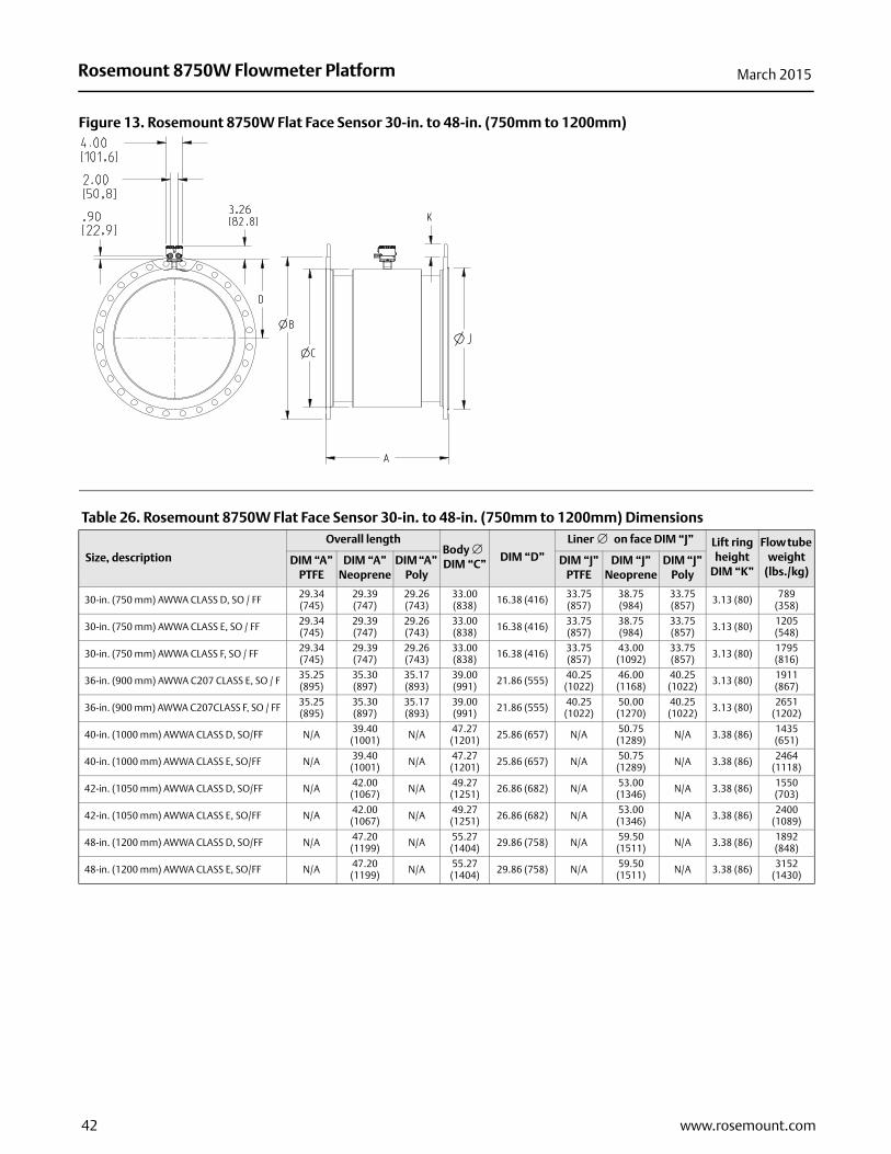
Rosemount 8750W Flowmeter Platform March 2015
Figure 13. Rosemount 8750W Flat Face Sensor 30-in. to 48-in. (750mm to 1200mm)
Table 26. Rosemount 8750W Flat Face Sensor 30-in. to 48-in. (750mm to 1200mm) Dimensions
Size, description
Overall lengthBody DIM “C”
DIM “D”
Liner on face DIM “J” Lift ring height
DIM “K”
Flow tube weight
(lbs./kg)DIM “A”
PTFEDIM “A”
NeopreneDIM “A”
PolyDIM “J”
PTFEDIM “J”
NeopreneDIM “J”
Poly
30-in. (750 mm) AWWA CLASS D, SO / FF 29.34 (745)
29.39 (747)
29.26 (743)
33.00 (838) 16.38 (416) 33.75
(857)38.75 (984)
33.75 (857) 3.13 (80) 789
(358)
30-in. (750 mm) AWWA CLASS E, SO / FF 29.34 (745)
29.39 (747)
29.26 (743)
33.00 (838) 16.38 (416) 33.75
(857)38.75 (984)
33.75 (857) 3.13 (80) 1205
(548)
30-in. (750 mm) AWWA CLASS F, SO / FF 29.34 (745)
29.39 (747)
29.26 (743)
33.00 (838) 16.38 (416) 33.75
(857)43.00 (1092)
33.75 (857) 3.13 (80) 1795
(816)
36-in. (900 mm) AWWA C207 CLASS E, SO / F 35.25 (895)
35.30 (897)
35.17 (893)
39.00 (991) 21.86 (555) 40.25
(1022)46.00 (1168)
40.25 (1022) 3.13 (80) 1911
(867)
36-in. (900 mm) AWWA C207CLASS F, SO / FF 35.25 (895)
35.30 (897)
35.17 (893)
39.00 (991) 21.86 (555) 40.25
(1022)50.00 (1270)
40.25 (1022) 3.13 (80) 2651
(1202)
40-in. (1000 mm) AWWA CLASS D, SO/FF N/A 39.40 (1001) N/A 47.27
(1201) 25.86 (657) N/A 50.75 (1289) N/A 3.38 (86) 1435
(651)
40-in. (1000 mm) AWWA CLASS E, SO/FF N/A 39.40 (1001) N/A 47.27
(1201) 25.86 (657) N/A 50.75 (1289) N/A 3.38 (86) 2464
(1118)
42-in. (1050 mm) AWWA CLASS D, SO/FF N/A 42.00 (1067) N/A 49.27
(1251) 26.86 (682) N/A 53.00 (1346) N/A 3.38 (86) 1550
(703)
42-in. (1050 mm) AWWA CLASS E, SO/FF N/A 42.00 (1067) N/A 49.27
(1251) 26.86 (682) N/A 53.00 (1346) N/A 3.38 (86) 2400
(1089)
48-in. (1200 mm) AWWA CLASS D, SO/FF N/A 47.20 (1199) N/A 55.27
(1404) 29.86 (758) N/A 59.50 (1511) N/A 3.38 (86) 1892
(848)
48-in. (1200 mm) AWWA CLASS E, SO/FF N/A 47.20 (1199) N/A 55.27
(1404) 29.86 (758) N/A 59.50 (1511) N/A 3.38 (86) 3152
(1430)
42 www.rosemount.com

Rosemount 8750W Flowmeter PlatformMarch 2015
Figure 14. Rosemount 8750W Flanged Sensor 1/2-in. to 48-in. (DN 15mm to 1200mm) Grounding Rings
A. Grounding RingB. Customer Supplied GasketC. FlowtubeD. Grounding Strap Hardware
A
B
C
D
Table 27. Rosemount 8750W Flanged Sensor 1/2-in. to 48-in. (15mm to 1200mm) Grounding Ring Dimensions
Line sizeSingle grounding ring
thicknessDouble grounding ring
thicknessMIN MAX MIN MAX
0.5-in. (15mm) 0.059 (1.5) N/A 0.12 (3) N/A1-in. (25mm) 0.059 (1.5) N/A 0.12 (3) N/A1.5-in. (40mm) 0.059 (1.5) N/A 0.12 (3) N/A2-in. (50mm) 0.059 (1.5) N/A 0.12 (3) N/A2.5-in. (65mm) 0.059 (1.5) N/A 0.12 (3) N/A3-in. (80mm) 0.059 (1.5) N/A 0.12 (3) N/A4-in. (100mm) 0.059 (1.5) N/A 0.12 (3) N/A5-in. (125mm) 0.059 (1.5) 0.12 (3) 0.12 (3) 0.24 (6.1)6-in. (150mm) 0.059 (1.5) N/A 0.12 (3) N/A8-in. (200mm) 0.059 (1.5) N/A 0.12 (3) N/A10-in. (250mm) 0.059 (1.5) N/A 0.12 (3) N/A12-in. (300mm) 0.059 (1.5) 0.12 (3) 0.12 (3) 0.24 (6.1)14-in. (350mm) 0.12 (3) 0.25 (6.4) 0.24 (6.1) 0.5 (12.7)16-in. (400mm) 0.12 (3) 0.25 (6.4) 0.24 (6.1) 0.5 (12.7)18-in. (450mm) 0.12 (3) 0.25 (6.4) 0.24 (6.1) 0.5 (12.7)20-in. (500mm) 0.12 (3) 0.25 (6.4) 0.24 (6.1) 0.5 (12.7)24-in. (600mm) 0.187 (4.7) 0.25 (6.4) 0.374 (9.5) 0.5 (12.7)30-in. (750mm) 0.187 (4.7) 0.25 (6.4) 0.374 (9.5) 0.5 (12.7)36-in. (900mm) 0.187 (4.7) 0.25 (6.4) 0.374 (9.5) 0.5 (12.7)40-in. (1000mm) 0.25 (6.4) N/A 0.5 (12.7) N/A42-in. (1050mm) 0.25 (6.4) N/A 0.5 (12.7) N/A48-in. (1200mm) 0.25 (6.4) N/A 0.5 (12.7) N/A
43www.rosemount.com

Rosemount 8750W Flowmeter Platform March 2015
Figure 15. Rosemount 8750W Wafer Sensor 11/2-in. to 8-in. (40mm to 200mm)
Table 28. Rosemount 8750W Wafer Sensor 11/2-in. to 8-in. (40mm to 200mm) Dimensions (in inches)
Size, description
Overall length Body
DIM “C”
AdapterLiner on
face DIM “J”
Flow tube weight
(lbs./kg)DIM “A” PTFE
Style A Style B
1.5-in. (40mm) WAFER UP TO ANSI - 300# / DIN PN40 2.88 (73) 3.29 (84)3.67 (93)
4.00 (102)
2.42 (61) 5 (2)
2-in. (50mm) WAFER UP TO ANSI - 300# / DIN PN40 3.32 (84) 3.92 (100)3.89 (99)
4.32 (110)
3.05 (77) 7 (3)
3-in. (80mm) WAFER UP TO ANSI - 300# / DIN PN40 4.82 (122) 5.17 (131)4.51 (115)
4.95 (126)
4.41 (112) 13 (6)
4-in. (100mm) WAFER UP TO ANSI - 300# / DIN PN40 6.03 (153) 6.39 (162)5.12 (130)
5.56 (141)
5.80 (147) 22 (10)
6-in. (150mm) WAFER UP TO ANSI - 300# / DIN PN40 7.08 (180) 8.57 (218)6.22 (158)
6.65 (169)
7.86 (200) 35 (16)
8-in. (200mm) WAFER UP TO ANSI - 300# / DIN PN40 9.06 (230) 10.63 (270)7.25 (184)
7.68 (195)
9.86 (250) 60 (27)
44 www.rosemount.com

Rosemount 8750W Flowmeter PlatformMarch 2015
45www.rosemount.com

Rosemount 8750W Flowmeter System00813-0300-4750, Rev AA
Product Data SheetMarch 2015
North America Regional Office
Emerson Process Management 8200 Market Blvd.Chanhassen, MN 55317, USA+1 800 522 6277 or +1 303 527 5200+1 303 530 8459
Latin America Regional OfficeEmerson Process Management Multipark Office CenterTurrubares Building, 3rd and 4th FloorGuachipelin de Escazu, Costa Rica
+1 506 2505 [email protected]
Europe Regional OfficeEmerson Process Management Flow B.V.Neonstraat 16718 WX EdeThe Netherlands
+31 (0) 318 495555+31 (0) 318 [email protected]
Asia Pacific Regional OfficeEmerson Process Management Asia Pacific Pte Ltd1 Pandan CrescentSingapore 128461
+65 6777 8211+65 6777 0947 [email protected]
Middle East and Africa Regional OfficeEmerson Process Management Emerson FZE P.O. Box 17033,Jebel Ali Free Zone - South 2Dubai, United Arab Emirates
+971 4 8118100+971 4 8865465 [email protected]
Standard Terms and Conditions of Sale can be found at: www.rosemount.com\terms_of_sale.The Emerson logo is a trademark and service mark of Emerson Electric Co.AMS and ProLink are registered trademarks of Emerson Process Management.
Rosemount and Rosemount logotype are registered trademarks of Rosemount, Inc.SMART Meter Verification is a trademark of Rosemount, Inc.HART is a registered trademark of FieldComm Group.All other marks are the property of their respective owners.© 2015 Rosemount Inc. All rights reserved.