Embed Size (px)
Citation preview
F1215 REV E
TABLE OF CONTENTS
Applications, Models, and Options . . . . . . . . . . . . . . . . . . 1
How it Works . . . . . . . . . . . . . . . . . . . . . . . . . . . . . . . . . . . 1
“SEEING IS BELIEVING”® . . . . . . . . . . . . . . . . . . . . . . . . 2
Dimensions and Specifications . . . . . . . . . . . . . . . . . . . . . 3
� Important Safety Precautions . . . . . . . . . . . . . . . . . . . 4
Installation Instructions . . . . . . . . . . . . . . . . . . . . . . . . . . . 5
12 VDC And 24 VDC Electric Pre-heater Installation . . . . 7
Water in Fuel Sensor (WIF) Installation . . . . . . . . . . . . . . . 8
Preventive Maintenance . . . . . . . . . . . . . . . . . . . . . . . . . . 9
Filter Change Procedure . . . . . . . . . . . . . . . . . . . . . . . . . 10
Visual Diagnostics With Clear Cover . . . . . . . . . . . . . . . . 11
Visual Diagnostics - Air vs . Vapor Bubbles . . . . . . . . . . . 12
Diagnostic Procedures - Air Leaks . . . . . . . . . . . . . . . . . 13
Diagnostic Procedures - Heater Testing . . . . . . . . . . . . . 14
Check Valve Diagnostics . . . . . . . . . . . . . . . . . . . . . . . . . 15
Service Parts . . . . . . . . . . . . . . . . . . . . . . . . . . . . . . . . . . 16
Warranty Policy . . . . . . . . . . . . . . . . . . . . . . . . . . . . . . . . 17
Parts Return Policy . . . . . . . . . . . . . . . . . . . . . . . . . . . . . 18
FOR UPDATED INFORMATION, VISIT WWW.DAVCO.COM
DIESEL PRO 243 Technical Manual

DIESEL PRO® 243TECHNICAL MANUALT e c h n o l o g y , L L C
1
DAVCO Technology, LLC P. O. Box 487 Saline, MI 48176 800-328-2611 www.davco.com F1215 REV E
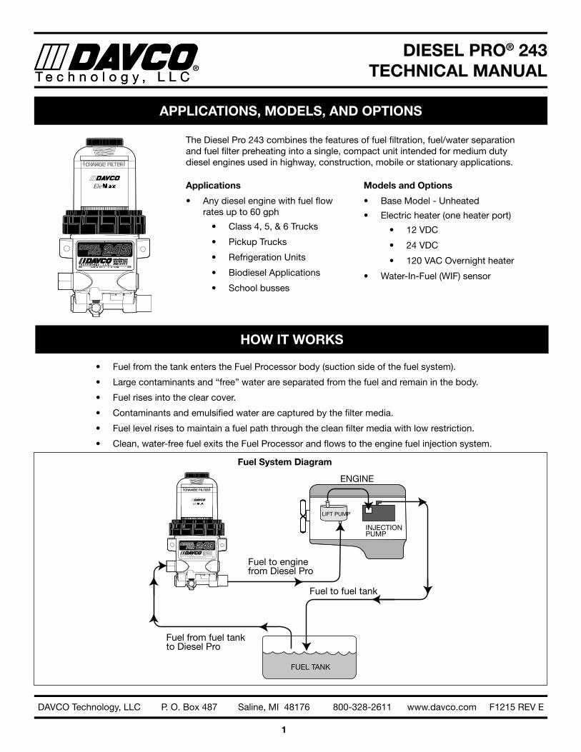
The Diesel Pro 243 combines the features of fuel filtration, fuel/water separation and fuel filter preheating into a single, compact unit intended for medium duty diesel engines used in highway, construction, mobile or stationary applications .
Applications
• Any diesel engine with fuel flow rates up to 60 gph
• Class 4, 5, & 6 Trucks
• Pickup Trucks
• Refrigeration Units
• Biodiesel Applications
• School busses
Models and Options
• Base Model - Unheated
• Electric heater (one heater port)
• 12 VDC
• 24 VDC
• 120 VAC Overnight heater
• Water-In-Fuel (WIF) sensor
FUEL TANK
ENGINE
LIFT PUMP
INJECTIONPUMP
Fuel from fuel tankto Diesel Pro
Fuel to fuel tank
Fuel to engine from Diesel Pro
Fuel System Diagram
HOW IT WORKS
APPLICATIONS, MODELS, AND OPTIONS
• Fuel from the tank enters the Fuel Processor body (suction side of the fuel system) .
• Large contaminants and “free” water are separated from the fuel and remain in the body .
• Fuel rises into the clear cover .
• Contaminants and emulsified water are captured by the filter media .
• Fuel level rises to maintain a fuel path through the clean filter media with low restriction .
• Clean, water-free fuel exits the Fuel Processor and flows to the engine fuel injection system .

DIESEL PRO® 243TECHNICAL MANUALT e c h n o l o g y , L L C
2
DAVCO Technology, LLC P. O. Box 487 Saline, MI 48176 800-328-2611 www.davco.com F1215 REV E
• See when NOT to change the fuel filter .
• See the condition of the fuel . Seeing what collects on the filter media or what’s happening inside the clear cover can help diagnose many fuel and mechanical conditions .
• “Filter on Top” configuration . Water and debris removed from the fuel falls to the lower chamber and stays away from the filter media resulting in longer filter life .
• Built in protection when priming the fuel filter . Unfiltered fuel is kept on the “dirty” side of the filter media during priming ensuring only clean fuel reaches the engine .
• Patented media . The “Best in Class” StrataPore™ media removes 98% of free and emulsified water over the life of the filter . This far exceeds the performance of cellulose media .
When new, the fuel level in the filter will be very low with minimal restriction. As the filter is used, contami-nants collect on the filter from the bottom up . Fuel rises on the filter indicating remaining filter life .
Fuel level at filter wrap level. Even though the fuel level is now more than half of the filter element, the fuel is still flowing through clean media at minimal restriction levels . The filter still has significant life remaining .
Fuel level increases in clear cover. As contaminants collect on the filter, the fuel rises to a non-contaminated section of the filter, providing optimal filtration while main-taining lowest restriction .
The filter element is now completely covered by fuel. At this point, all of the media’s surface area is utilized . Restriction is increasing and the filter element should be changed at the next scheduled maintenance interval .
“SEEING IS BELIEVING”®
DIESEL PRO® 243TECHNICAL MANUALT e c h n o l o g y , L L C
3
DAVCO Technology, LLC P. O. Box 487 Saline, MI 48176 800-328-2611 www.davco.com F1215 REV E
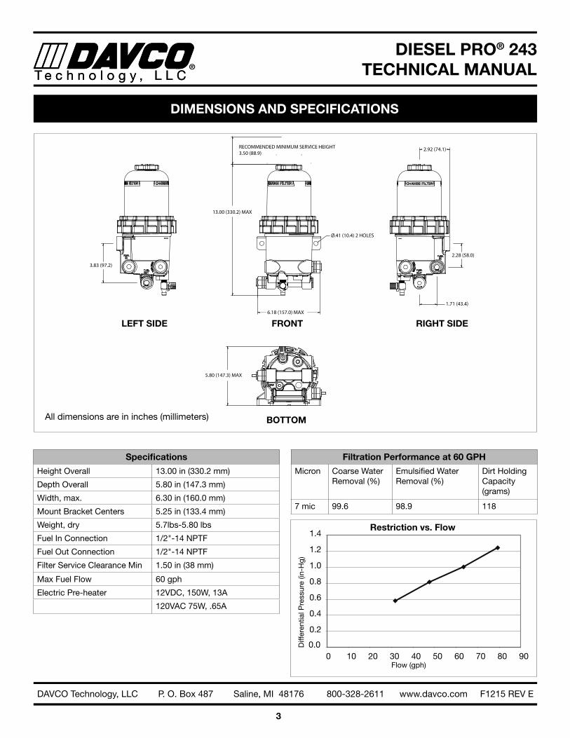
DIMENSIONS AND SPECIFICATIONS
6.18 (157.0) MAX
13.00 (330.2) MAX
Ø.41 (10.4) 2 HOLES
RECOMMENDED MINIMUM SERVICE HEIGHT3.50 (88.9)
5.80 (147.3) MAX
3.83 (97.2)
2.28 (58.0)
1.71 (43.4)
2.92 (74.1)
LEFT SIDE
BOTTOM
RIGHT SIDEFRONT
All dimensions are in inches (millimeters)
Specifications
Height Overall 13 .00 in (330 .2 mm)
Depth Overall 5 .80 in (147 .3 mm)
Width, max . 6 .30 in (160 .0 mm)
Mount Bracket Centers 5 .25 in (133 .4 mm)
Weight, dry 5 .7lbs-5 .80 lbs
Fuel In Connection 1/2"-14 NPTF
Fuel Out Connection 1/2"-14 NPTF
Filter Service Clearance Min 1 .50 in (38 mm)
Max Fuel Flow 60 gph
Electric Pre-heater 12VDC, 150W, 13A
120VAC 75W, .65A
Filtration Performance at 60 GPH
Micron Coarse Water Removal (%)
Emulsified Water Removal (%)
Dirt Holding Capacity (grams)
7 mic 99 .6 98 .9 118
0.0
0.2
0.4
0.6
0.8
1.0
1.2
1.4
0 10 20 30 40 50 60 70 80 90
Restriction vs. Flow
Flow (gph)
Diff
eren
tial P
ress
ure
(in-H
g)
DIESEL PRO® 243TECHNICAL MANUALT e c h n o l o g y , L L C
4
DAVCO Technology, LLC P. O. Box 487 Saline, MI 48176 800-328-2611 www.davco.com F1215 REV E
IMPORTANT SAFETY PRECAUTIONS
General Safety Precautions• Read all instructions before use to avoid injury .
• To avoid serious injury or death, follow the safety information in this document .
• Keep this manual . If you need to replace the manual, call customer service at 800-328-2611 or visit www .davco .com/documents for a replacement .
• Read all product safety labels .
• Refer to appropriate regulations for environmental and workplace safety rules .
WARNING: To prevent personal injury• Scalding hazard: When diesel fuel is circulated through an operating engine, it can become very hot . Do not al-
low fuel to come in contact with eyes or unprotected skin . Allow the engine and fuel to cool to ambient tempera-ture before replacing the fuel filter or performing service operations which could result in spillage of fuel from the fuel system .
• Fire Prevention: Heated fuel can form combustible vapor mixtures in the area around the fuel source . To elimi-nate the potential for fire, keep open flames, sparks or other potential ignition sources away from the work area . Do not smoke during filter replacement or service operations .
• Inhalation Precaution: Always perform engine or vehicle fuel system maintenance in a well ventilated area that is kept free of bystanders .
• The ignition key must be in the off position, unless otherwise directed . To avoid unintentional engine startup, use a lockout key and/or signage to alert personnel that work is being performed .
Government Regulations• Engine fluids (oil, fuel, and coolant) may be a hazard to human health and the environment . Handle all fluids and
other contaminated materials (such as filters and rags) in accordance with applicable regulations . Recycle or dis-pose of engine fluids, filters, and other contaminated materials according to applicable regulations .
DIESEL PRO® 243TECHNICAL MANUALT e c h n o l o g y , L L C
5
DAVCO Technology, LLC P. O. Box 487 Saline, MI 48176 800-328-2611 www.davco.com F1215 REV E
Installation LocationThe Diesel Pro must be installed between the fuel tank and the fuel transfer pump . In some cases, the Diesel Pro can be used as the only fuel filter in the system . This is generally dependent on the engine model year . Consult the engine manufacturer for their recommendation . If the Diesel Pro can be used as a single filter, DAVCO offers a diverter cap to replace the secondary filter . (See Diverter Cap Installation section)
Mounting the Diesel ProMount the Diesel Pro keeping the following points in mind:
• Do not install the Diesel Pro directly on the engine.
• Mount vertically with the cover and element pointing up .
• Make sure there is enough top and side clearance for the cover to be conveniently removed for filter replace-ment (3 .5" minimum) .
• The Diesel Pro MUST be installed so that the Filter Element is above the “FULL” level of the fuel tank . If mounted below full tank level, a shut off valve will be required at the inlet to allow filter changes without over-flow of fuel .
1 . With the engine shut down and at ambient temperature, close the fuel shutoff valve (if equipped) and place a suitable container under the fuel filters .
2 . Remove the primary fuel filter element assembly, sedi-menter, and/or water separator . Drain the used element and dispose of it in an environmentally responsible manner, according to state and/or federal (EPA) recom-mendations . The fuel can be returned to the tank .
3 . Mount the Diesel Pro in the desired location using 3/8" Grade 8 hardware .
Fuel Line RoutingTo minimize fuel system restriction, observe the follow-ing guidelines when plumbing the fuel system:
• Keep the fuel line routing as smooth as possible with no low-hanging loops which can trap water .
• Use 90° elbows only when necessary .
• If the fuel hoses are cut to length on the job, be sure that the inner liner of the fuel hose is not cut by the fit-ting, which can cause check valve performance issues . Make sure hoses are clean and free of debris before installing .
• To avoid damaging the aluminum Diesel Pro body, do not overtighten fuel lines or fuel line fittings .
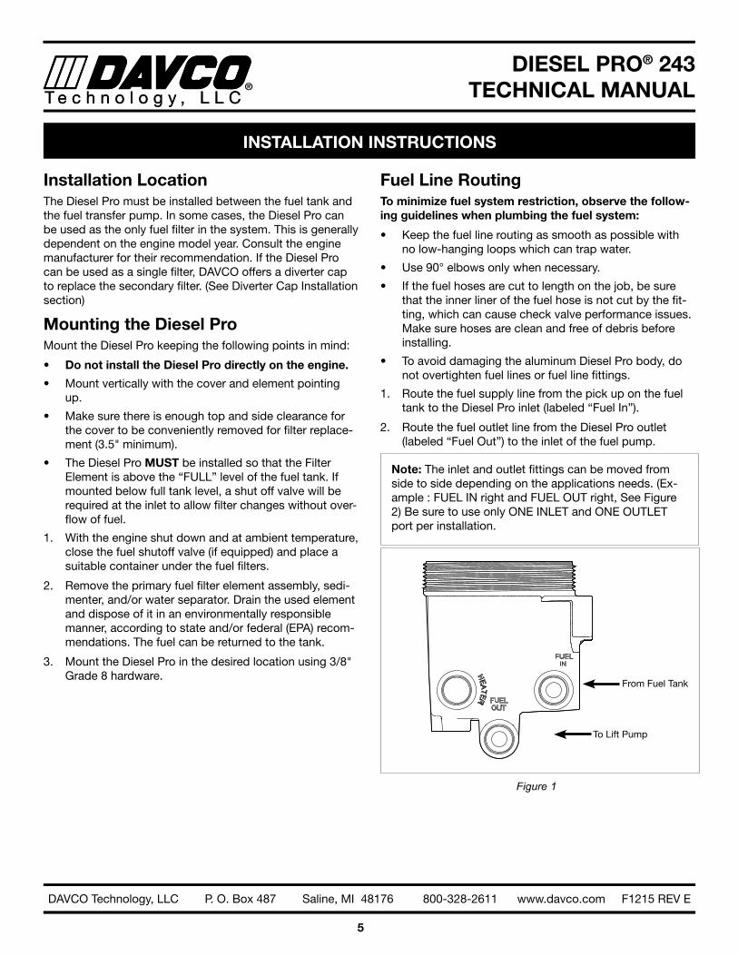
1 . Route the fuel supply line from the pick up on the fuel tank to the Diesel Pro inlet (labeled “Fuel In”) .
2 . Route the fuel outlet line from the Diesel Pro outlet (labeled “Fuel Out”) to the inlet of the fuel pump .
Note: The inlet and outlet fittings can be moved from side to side depending on the applications needs . (Ex-ample : FUEL IN right and FUEL OUT right, See Figure 2) Be sure to use only ONE INLET and ONE OUTLET port per installation .
From Fuel Tank
To Lift Pump
Figure 1
INSTALLATION INSTRUCTIONS
DIESEL PRO® 243TECHNICAL MANUALT e c h n o l o g y , L L C
6
DAVCO Technology, LLC P. O. Box 487 Saline, MI 48176 800-328-2611 www.davco.com F1215 REV E
Priming the Fuel System1 . Check to make sure the drain valve at the base of the
Diesel Pro is closed .
2 . Remove the vent cap from the top of the clear cover . Fill the Diesel Pro full with clean fuel . Reinstall the vent cap . Tighten the vent cap by hand until it clicks .
3 . Start the engine . When the lubrication system reaches its normal operating pressure, increase engine RPM to high idle for one to two minutes . After the air is purged loosen the vent cap until the fuel level lowers to just above the collar . Tighten the vent cap by hand until it clicks .
Note: The clear filter cover will not fill completely during engine operation . It will gradually fill over time and the fuel level will rise as the filter becomes contaminated .
Diverter Cap InstallationIf a single fuel filter system is approved by the engine manufacturer, the following steps are to be taken to install a diverter cap properly .
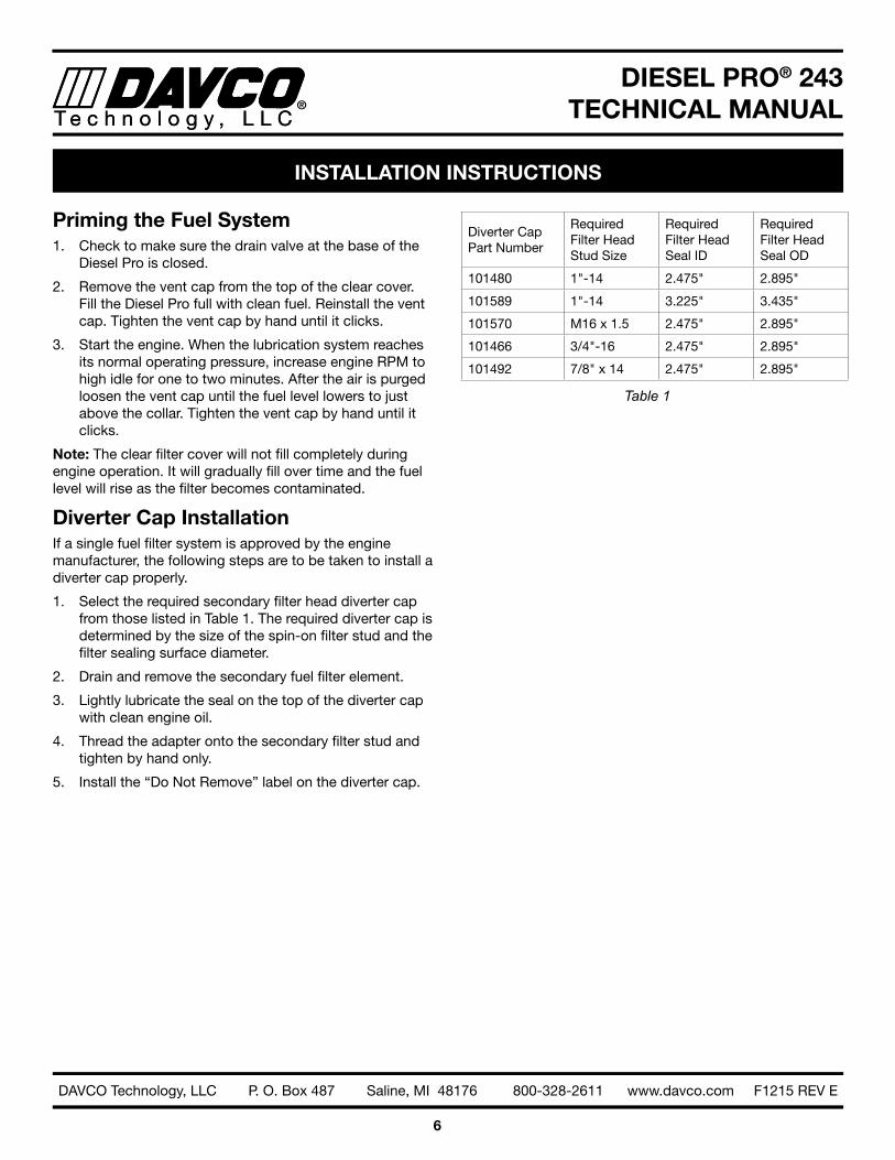
1 . Select the required secondary filter head diverter cap from those listed in Table 1 . The required diverter cap is determined by the size of the spin-on filter stud and the filter sealing surface diameter .
2 . Drain and remove the secondary fuel filter element .
3 . Lightly lubricate the seal on the top of the diverter cap with clean engine oil .
4 . Thread the adapter onto the secondary filter stud and tighten by hand only .
5 . Install the “Do Not Remove” label on the diverter cap .
Diverter Cap Part Number
Required Filter Head Stud Size
Required Filter Head Seal ID
Required Filter Head Seal OD
101480 1"-14 2 .475" 2 .895"
101589 1"-14 3 .225" 3 .435"
101570 M16 x 1 .5 2 .475" 2 .895"
101466 3/4"-16 2 .475" 2 .895"
101492 7/8" x 14 2 .475" 2 .895"
Table 1
INSTALLATION INSTRUCTIONS
DIESEL PRO® 243TECHNICAL MANUALT e c h n o l o g y , L L C
7
DAVCO Technology, LLC P. O. Box 487 Saline, MI 48176 800-328-2611 www.davco.com F1215 REV E
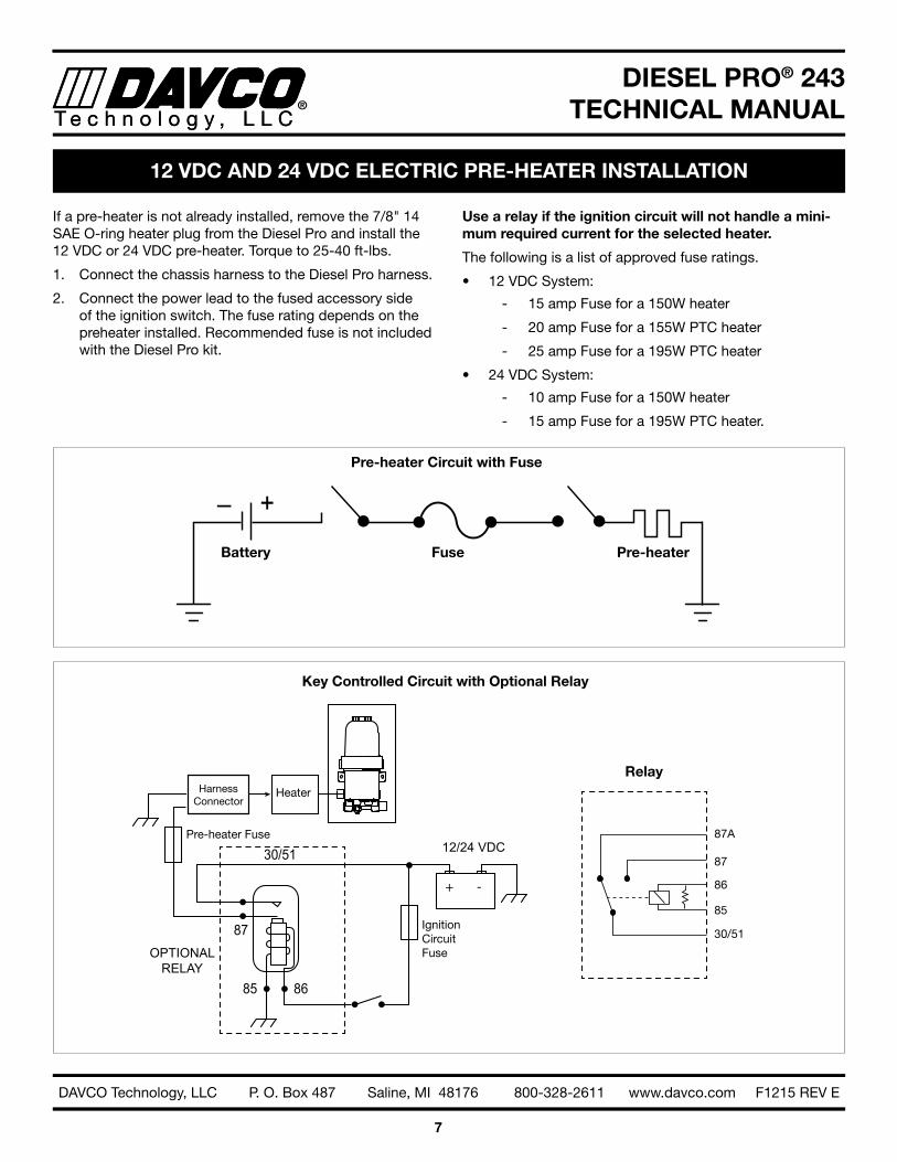
If a pre-heater is not already installed, remove the 7/8" 14 SAE O-ring heater plug from the Diesel Pro and install the 12 VDC or 24 VDC pre-heater . Torque to 25-40 ft-lbs .
1 . Connect the chassis harness to the Diesel Pro harness .
2 . Connect the power lead to the fused accessory side of the ignition switch . The fuse rating depends on the preheater installed . Recommended fuse is not included with the Diesel Pro kit .
Use a relay if the ignition circuit will not handle a mini-mum required current for the selected heater.
The following is a list of approved fuse ratings .
• 12 VDC System:
- 15 amp Fuse for a 150W heater
- 20 amp Fuse for a 155W PTC heater
- 25 amp Fuse for a 195W PTC heater
• 24 VDC System:
- 10 amp Fuse for a 150W heater
- 15 amp Fuse for a 195W PTC heater .
12 VDC AND 24 VDC ELECTRIC PRE-HEATER INSTALLATION
+–
85
30/51
87
86
12/24 VDC
OPTIONALRELAY
+ -
Heater
Pre-heater Fuse
HarnessConnector
Ignition Circuit Fuse
87A
87
86
85
30/51
Key Controlled Circuit with Optional Relay
Pre-heater Circuit with Fuse
Relay
Battery Pre-heaterFuse
DIESEL PRO® 243TECHNICAL MANUALT e c h n o l o g y , L L C
8
DAVCO Technology, LLC P. O. Box 487 Saline, MI 48176 800-328-2611 www.davco.com F1215 REV E
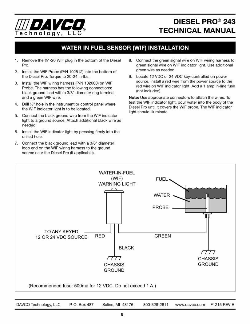
1 . Remove the ½"-20 WIF plug in the bottom of the Diesel Pro .
2 . Install the WIF Probe (P/N 102512) into the bottom of the Diesel Pro . Torque to 20-24 in-lbs .
3 . Install the WIF wiring harness (P/N 102600) on WIF Probe . The harness has the following connections: black ground lead with a 3/8" diameter ring terminal and a green WIF wire .
4 . Drill ½" hole in the instrument or control panel where the WIF indicator light is to be located .
5 . Connect the black ground wire from the WIF indicator light to a ground source . Attach additional black wire as needed .
6 . Install the WIF indicator light by pressing firmly into the drilled hole .
7 . Connect the black ground lead with a 3/8" diameter loop end on the WIF wiring harness to the ground source near the Diesel Pro (if applicable) .
8 . Connect the green signal wire on WIF wiring harness to green signal wire on WIF indicator light . Use additional green wire as needed .
9 . Locate 12 VDC or 24 VDC key-controlled on power source . Install a red wire from the power source to the red wire on WIF indicator light . Add a 1 amp in-line fuse (not included) .
Note: Use appropriate connectors to attach the wires . To test the WIF indicator light, pour water into the body of the Diesel Pro until it covers the WIF probe . The WIF indicator light should illuminate .
WATER IN FUEL SENSOR (WIF) INSTALLATION
CHASSISGROUND
FUEL
WATER
PROBE
GREEN
CHASSISGROUND
BLACK
REDTO ANY KEYED
12 OR 24 VDC SOURCE
(Recommended fuse: 500ma for 12 VDC. Do not exceed 1 A.)
WATER-IN-FUEL(WIF)
WARNING LIGHT
DIESEL PRO® 243TECHNICAL MANUALT e c h n o l o g y , L L C
9
DAVCO Technology, LLC P. O. Box 487 Saline, MI 48176 800-328-2611 www.davco.com F1215 REV E
PREVENTIVE MAINTENANCE
• Weekly – Drain water
• Turn off the engine and open the vent cap .
• Place a suitable eight ounce, plastic or metal container under the drain valve at the base of the Diesel Pro and open the valve .
• Water will flow into the container . When fuel begins to flow out the drain, close the drain valve . Drain the least amount of fuel as possible .
• Tighten the vent cap by hand until it clicks .
• Start the engine . Raise the RPM for one minute to purge the air from the system .
• Every filter change
• Change the cover and vent cap o-rings (included with the service filter kit) .
• Every 12 months
• Check all electrical connections for corrosion . Check all fuel fittings for leaks .
• Extreme winter or salt corrosion environments may require lubrication of the collar threads with anti-seize lubricant every 180 days .
DIESEL PRO® 243TECHNICAL MANUALT e c h n o l o g y , L L C
10
DAVCO Technology, LLC P. O. Box 487 Saline, MI 48176 800-328-2611 www.davco.com F1215 REV E
FILTER CHANGE PROCEDURE
For filter selection visit www.davco.com for the cor-rect filter for your application or call DAVCO Customer Service at 800-328-2611.
1 . Remove the vent cap and open the drain valve to drain the fuel below the collar level .
2 . Remove the collar (using the DAVCO collar wrench or a common tool) then remove the clear cover .
3 . Remove the filter, cover and vent cap seals . Dispose of the filter and the seals properly .
4 . Using a clean shop rag, clean the cover, the collar and threads on the Diesel Pro body .
5 . Install a new filter, cover seal and vent cap seal .
6 . Reinstall the clear cover and collar . Simultaneously apply downward pressure to the top of the clear cover
until it is seated on the body of the Diesel Pro and hand tighten the collar until it no longer spins freely . Torque the cover assembly by rotating the collar clockwise three additional ribs using the collar wrench (~18 ft-lbs) .
7 . Prime the unit by filling the clear cover with clean diesel fuel until it reaches the top of the filter .
8 . Install the vent cap . Tighten the vent cap by hand until it clicks .
9 . Start the engine and run for one minute . Slowly open the vent cap and allow the fuel to drop to about one inch above the collar .
10 . Tighten the vent cap by hand until it clicks .
Note: It is normal for the fuel level to vary after the initial start-up and during engine operation . Filter performance is not affected .
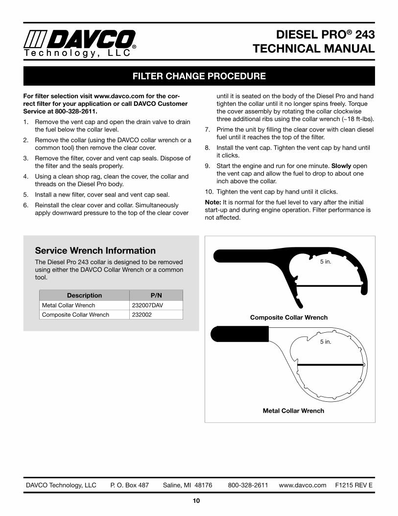
Service Wrench InformationThe Diesel Pro 243 collar is designed to be removed using either the DAVCO Collar Wrench or a common tool .
Description P/N
Metal Collar Wrench 232007DAV
Composite Collar Wrench 232002
Metal Collar Wrench
Composite Collar Wrench
5 in .
5 in .
DIESEL PRO® 243TECHNICAL MANUALT e c h n o l o g y , L L C
11
DAVCO Technology, LLC P. O. Box 487 Saline, MI 48176 800-328-2611 www.davco.com F1215 REV E
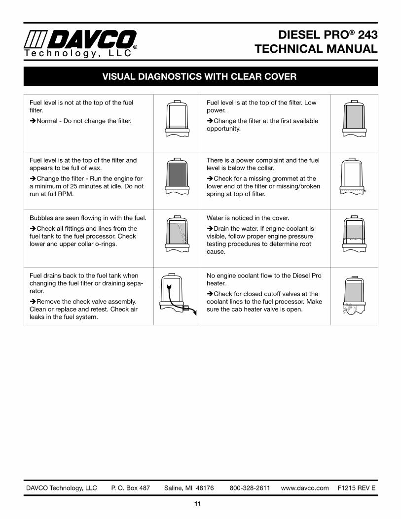
Fuel level is not at the top of the fuel filter .
ÎNormal - Do not change the filter .
Fuel level is at the top of the filter . Low power .
ÎChange the filter at the first available opportunity .
Fuel level is at the top of the filter and appears to be full of wax .
ÎChange the filter - Run the engine for a minimum of 25 minutes at idle . Do not run at full RPM .
There is a power complaint and the fuel level is below the collar .
ÎCheck for a missing grommet at the lower end of the filter or missing/broken spring at top of filter .
Bubbles are seen flowing in with the fuel .
ÎCheck all fittings and lines from the fuel tank to the fuel processor . Check lower and upper collar o-rings .
Water is noticed in the cover .
ÎDrain the water . If engine coolant is visible, follow proper engine pressure testing procedures to determine root cause .
Fuel drains back to the fuel tank when changing the fuel filter or draining sepa-rator .
ÎRemove the check valve assembly . Clean or replace and retest . Check air leaks in the fuel system .
No engine coolant flow to the Diesel Pro heater .
ÎCheck for closed cutoff valves at the coolant lines to the fuel processor . Make sure the cab heater valve is open .
VISUAL DIAGNOSTICS WITH CLEAR COVER

DIESEL PRO® 243TECHNICAL MANUALT e c h n o l o g y , L L C
12
DAVCO Technology, LLC P. O. Box 487 Saline, MI 48176 800-328-2611 www.davco.com F1215 REV E
VISUAL DIAGNOSTICS - AIR VS. VAPOR BUBBLES
Air Bubbles
Air bubbles are caused by any air leak on the vacuum (suc-tion) side of the fuel system from the fuel tank pick-up to, and including, the lift pump . (See Figure 2)
If there is an air leak in the fuel system, air bubbles will be present in the clear cover of the Diesel Pro . Follow test procedures outlined in Diagnostic Procedures (page 13) for air leak diagnostics . If there are no bubbles present in the Diesel Pro cover and the engine continues to run rough, lopes or has a loss of power, there may be an air leak between the Diesel Pro outlet port and lift pump inlet . This type of air bubble can be seen if a sight tube is installed at the lift pump inlet . Air bubbles may also be visible in the fuel return (spill) hose out of the fuel gallery . These leaks are easily eliminated by checking and torquing the fuel fittings in the area of the leak .
NOTE 1: A quick procedure to determine if the air leak is between the fuel tank and the Diesel Pro is to remove the Diesel Pro inlet hose and route a new hose from the Die-sel Pro inlet into a container of fuel or the fuel tank fill cap opening . Start the engine and check for bubbles .
If there are no air leak symptoms, but bubbles are present in a sight tube at the fuel lift pump inlet, they are most likely vapor bubbles .
Vapor Bubbles
All diesel fuel has some level of entrained air caused by the natural splashing that occurs in the fuel tank during normal vehicle or equipment operation . Vapor bubbles develop in the Diesel Pro because the pressure inside the Diesel Pro is lower than the atmospheric pressure in the fuel tank . Vapor bubbles can vary from champagne size up to ¼" in diam-eter . They may increase in size or volume as engine rpm increases . The lower pressure draws the entrained air/vapor out of the fuel and these bubbles will be visible as the fuel exits the Diesel Pro . (See Figure 3) As the fuel enters the lift pump, it is pressurized and the bubbles are compressed back into the fuel . There will be no bubbles on the fuel re-turn side of the system . These vapor bubbles will not affect the performance of the engine .
NOTE 2: An easy way to determine the difference between vapor and air bubbles is by temporarily removing the filter element from the Diesel Pro . Fill the cover with clean diesel fuel, replace the vent cap (tighten the vent cap by hand until it clicks ) and re-run the outlet fitting sight glass test . If there are no bubbles present in the sight glass then they were vapor . If bubbles are still present then they are air . If air bubbles still exist, re-run the test in NOTE 1 to eliminate the chassis plumbing as a variable .
There is no troubleshooting or repair procedure re-quired for vapor bubbles. Vapor bubbles do not cause performance issues and will not be present after the lift pump.
There are two kinds of bubbles that may be visible at the fuel pump inlet of a diesel fuel system. The bubbles can be characterized as either air bubbles or vapor bubbles.
Figure 2 Figure 3
AIR BUBBLES
DIESEL PRO OR OTHER PRIMARYFILTER
FUEL RETURN
ENGINE
LIFT PUMP
DIESEL PRO OR OTHER PRIMARYFILTER
FUEL RETURN
ENGINE
LIFT PUMP
VAPORBUBBLES

DIESEL PRO® 243TECHNICAL MANUALT e c h n o l o g y , L L C
13
DAVCO Technology, LLC P. O. Box 487 Saline, MI 48176 800-328-2611 www.davco.com F1215 REV E
Air LeaksEvery Diesel Pro is factory tested for leaks and is identified with a traceable number prior to shipment . Most field issues associated with leaks are related to loose fittings . These leaks are easily eliminated by checking and torquing the fuel fittings in the area of the leak . Some fittings may also require the application of liquid Teflon sealer .
Note: All suction side fuel filters experience bubbles . It is normal to see champagne size bubbles in the Diesel Pro cover, at the Diesel Pro outlet or at the lift pump .
IN ORDER TO RETURN A DIESEL PRO FOR EVALUA-TION, THE FOLLOWING PROCEDURES/TESTS MUST BE COMPLETED BEFORE REQUESTING A DAVCO RGA (RETURN GOODS AUTHORIZATION) NUMBER.
Air bubbles will be visible in the clear cover of the Diesel Pro if the leak originates between the fuel tank up and the Diesel Pro . The following is a quick test to isolate the air leak source .
A . Bubbles Visible: Remove the Diesel Pro inlet hose .
i . Install a jumper hose from the Diesel Pro to the fuel tank (through the fill cap) or to a container of fuel .
ii . Start the engine . If this eliminates the air bubbles, the air source is at the fuel tank fittings or hose connections .
1 . Tighten all fittings and connectors
2 . Retest
iii . If air bubbles persist, the air source is on the Diesel Pro side of the system:
1 . Tighten all fittings on the Diesel Pro .
2 . Hand tighten the top collar .
3 . If the drain valve is suspected, install a plug in place of the drain valve (for test purposes only) .
iv . If air bubbles continue to persist, test as follows:
1 . Remove the Diesel Pro from the chas-sis .
2 . Plug the fuel outlet port . Do not re-move filter, cover/collar, vent cap, drain
valve and/or check valve . If the Diesel Pro is equipped with a preheater, do not remove the preheater .
3 . Apply 15 PSI of air pressure at the fuel inlet . Immerse the Diesel Pro in a tank of water and look for air bubbles .
4 . Correct the source of the air leak and retest .
B. Bubbles Not Visible: If there are symptoms of sucking air (indicated by engine loping/rough run-ning performance/power loss, etc .) and there are no bubbles in the clear cover, the air leak is either at the Diesel Pro outlet fitting, vent cap o-ring, the lift pump inlet connection, or the fuel hose/connections to the lift pump . Inspect and tighten fittings as needed .
I. Excessive Restriction: If the fuel level is at the top of the filter, replace the fuel filter . The Diesel Pro will not cause excess system restriction if the fuel level is below the top of the filter . The only exception is if the grommet is not installed in the bottom of the filter element .
II . Loss of Prime: When air is introduced into the fuel system, (i .e . draining water from the Diesel Pro or when replacing the fuel filter) a check valve is needed to keep the fuel system primed from the Diesel Pro back to the fuel tank . A check valve is standard with every Diesel Pro .
A . To test for proper check valve operation, remove the fuel inlet hose and open the vent cap . Fuel should not flow out of the Diesel Pro , although a slight seepage of fuel is normal .
B . If fuel drains back to the fuel tank, remove the check valve . Clean and inspect . Replace the as-sembly if any cuts, grooves or nicks are evident . Reinstall the check valve assembly .
DIAGNOSTIC PROCEDURES - AIR LEAKS

DIESEL PRO® 243TECHNICAL MANUALT e c h n o l o g y , L L C
14
DAVCO Technology, LLC P. O. Box 487 Saline, MI 48176 800-328-2611 www.davco.com F1215 REV E
DIAGNOSTIC PROCEDURES - HEATER TESTING
There are various configurations of electric pre-heaters and thermoswitches available for the Diesel Pro . These include 12VDC pre-heaters, 24VDC pre-heaters, 120VAC pre-heat-ers/thermoswitches, and combination pre-heater thermo-switches . The voltage and wattage ratings are stamped either on the sheath or the hex of each component for identification .
Equipment Needed• A precision low resistance ohm meter capable of mea-
suring 1/10th ohm or less .
• Current flow meter (clamp-on type for DC current) .
• Ice, dry-ice, CO2 or some means of chilling the thermo-switch .
• A flameless source of heat . (ie: infrared heat lamp, etc .) Note: A Vortex tube is a good tool to heat and cool for testing .
� DO NOT USE a test light that has a wire probe for any of these tests. If the wiring insulation is punctured, moisture and road salt can penetrate into the wires creating a corrosion issue and potential failure.
Draining the Diesel Pro1 . Shut off the engine and set the parking brake .
2 . Attach a length of hose to the drain valve and place a receptacle under the Diesel Pro .
3 . Loosen the vent cap on top of the clear housing . Open the drain valve and drain the fuel into the receptacle .
4 . When the fuel is drained, close the drain valve .
Pre-heater Operation Test1 . Disconnect the pre-heater from the harness .
2 . Connect the ohm meter leads to the pins of the pre-heater . For heaters with one pin, connect to the pin and the bushing . Use the following to determine whether the pre-heater resistance value is in the ac-ceptable range .
Pre-heater Watts Resistance Range (ohms)
12VDC (two pin) 250 W 0 .6 to 0 .8 @ 77°F (25°C)
12VDC (single pin) 250 W 0 .6 to 0 .8 @ 77°F (25°C)
12VDC (single pin) 150 W 0 .8 to 1 .1 @ 77°F (25°C)
12VDC (two pin) 150 W 0 .8 to 1 .1 @ 77°F (25°C)
24VDC (two pin) 250 W 2 to 2 .5 @ 77°F (25°C)
24VDC (single pin) 250 W 1 .8 to 2 .3 @ 77°F (25°C)
24VDC (single pin) 150 W 3 .6 to 4 .1 @ 77°F (25°C)
24VDC (two pin) 150 W 3 .6 to 4 .1 @ 77°F (25°C)
120VAC 75 W 173 to 203 @ 77°F (25°C)
120VAC 37 W 369 to 411 @ 77°F (25°C)
Combination Pre-heater Thermoswitch Performance Test1 . Disconnect the harness from the heater/thermoswitch
combination unit .
2 . Using one of the cooling methods listed under "Equip-ment Needed", reduce the temperature of the thermo-switch to below 40° F .
3 . Connect the ohm meter leads to the pre-heater pins . Use Table 1 to determine whether the pre-heater resis-tance value is in the acceptable range .
4 . Using one of the pre-heating devices listed under “Equipment Needed”, raise the temperature of the combination pre-heater to 70°F . The ohm meter should read “open circuit” for the combination units .
12 VDC PTC/24VDC Performance Test1 . Disconnect the harness from the heater .
2 . Connect the ohm meter leads to the pins of the heater . Use the following to determine whether the pre-heater resistance value is in the acceptable range .
PTC Heater Watts Resistance Range (ohms)
12VDC (PTC) 195 W 0 .4 to 0 .6 @ 77°F (25°C)
24VDC (PTC) 195 W 2 .0 to 3 .0 @ 77°F (25°C)
12VDC (PTC) 155W 0 .95 to 1 .2 @ 77°F (25°C)

DIESEL PRO® 243TECHNICAL MANUALT e c h n o l o g y , L L C
15
DAVCO Technology, LLC P. O. Box 487 Saline, MI 48176 800-328-2611 www.davco.com F1215 REV E
1 . Remove the vent cap and open the drain valve . Drain the Diesel Pro 243 completely .
2 . Remove the collar, cover and the filter .
3 . Remove the check-valve assembly . (see Figure 4)
4 . Clean and inspect the check-valve . If the check valve appears damaged, order P/N 240033DAV .
5 . Reinstall the check-valve assembly into the Diesel Pro 243 body at 5-7 ft-lbs . of torque .
6 . Install the filter cover and collar and seals .
7 . Prime the unit by filling the clear cover with clean diesel fuel until it reaches the top of the filter .
8 . Install the vent cap . Tighten the vent cap by hand until it clicks .
9 . Start the engine and run for one minute . Slowly open the vent cap and allow the fuel to drop to about one inch above the collar .
10 . Tighten the vent cap by hand until it clicks .
Note: It is normal for the fuel level to vary after the initial start-up and during engine operation . Filter performance is not affected .
Figure 4
CHECK VALVE DIAGNOSTICS
DIESEL PRO® 243TECHNICAL MANUALT e c h n o l o g y , L L C
16
DAVCO Technology, LLC P. O. Box 487 Saline, MI 48176 800-328-2611 www.davco.com F1215 REV E
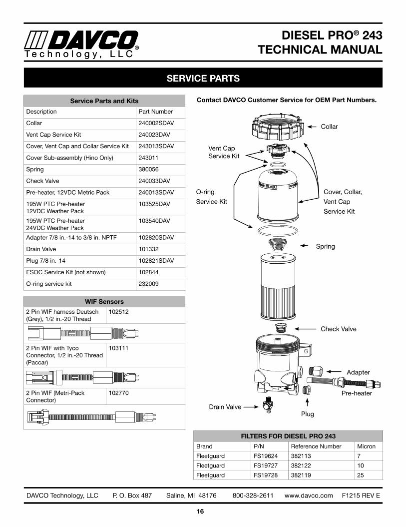
SERVICE PARTS
Contact DAVCO Customer Service for OEM Part Numbers.
Drain Valve
Adapter
Plug
Check Valve
Collar
Cover, Collar,
Vent Cap
Service Kit
Spring
Pre-heater
Vent Cap Service Kit
O-ring
Service Kit
Service Parts and Kits
Description Part Number
Collar 240002SDAV
Vent Cap Service Kit 240023DAV
Cover, Vent Cap and Collar Service Kit 243013SDAV
Cover Sub-assembly (Hino Only) 243011
Spring 380056
Check Valve 240033DAV
Pre-heater, 12VDC Metric Pack 240013SDAV
195W PTC Pre-heater 12VDC Weather Pack
103525DAV
195W PTC Pre-heater 24VDC Weather Pack
103540DAV
Adapter 7/8 in .-14 to 3/8 in . NPTF 102820SDAV
Drain Valve 101332
Plug 7/8 in .-14 102821SDAV
ESOC Service Kit (not shown) 102844
O-ring service kit 232009
WIF Sensors
2 Pin WIF harness Deutsch (Grey), 1/2 in .-20 Thread
102512
2 Pin WIF with Tyco Connector, 1/2 in .-20 Thread (Paccar)
103111
2 Pin WIF (Metri-Pack Connector)
102770
FILTERS FOR DIESEL PRO 243
Brand P/N Reference Number Micron
Fleetguard FS19624 382113 7
Fleetguard FS19727 382122 10
Fleetguard FS19728 382119 25
DIESEL PRO® 243TECHNICAL MANUALT e c h n o l o g y , L L C
17
DAVCO Technology, LLC P. O. Box 487 Saline, MI 48176 800-328-2611 www.davco.com F1215 REV E
Product WarrantyDiesel Pro® 243, Diesel Pro® 245, Fuel Pro® 382, Fuel Pro® 482, Fuel Pro® 483, Fuel Pro® 485, Fuel Pro® 486, Fuel Pro® 487, Industrial Pro®, Shop Pro®, Pro-Chek®, Sea Pro® Please review DAVCO’s Product Warranty terms and conditions carefully before installing and/or using a DAVCO product . By installing and/or using the product, you agree to be bound by the following:
DAVCO Technology, LLC warrants these products to be free of defects in material and workmanship for five-years, 500,000 miles or 10,000 hours (whichever comes first) and electrical parts for two-years, 200,000 miles or 4,000 hours (whichever comes first) from the purchase date* . The Shop Pro motor has a one-year warranty from the purchase date .
REN Products, EyeMax®, Electronic Gauges, Electronic Dipsticks and Fuel Pro® 384 DAVCO Technology, LLC warrants these products to be free of defects in material and workmanship for two-years or 200,000 miles (whichever comes first) from the purchase date .
This Warranty does not apply to:• Failure or inadequate performance due to improper installation, misuse, misapplication, faulty installation, alteration/
modification, poor maintenance, neglect, accident, or conditions resulting from actions outside DAVCO’s control, in-cluding but not limited to contaminated and unapproved fluids .
• Downtime, loss of use, loss of profits or income, loss of capital, cost of substitute equipment, living expenses, claims by purchaser’s customers or other third parties, or other incidental, special or consequential damages .
• Attachments, accessory items, and parts not manufactured or distributed by DAVCO .
• Any aftermarket or OEM component not approved specifically to work with a DAVCO manufactured product
• Product that has been installed with aftermarket parts or altered or modified in any way .
• Normal wear and tear, abuse, vandalism, acts of God, improper storage or handling, disasters such as flood, fire, or war, failure to operate, maintain or repair in accordance with instructions, or failure to repair the vehicle into which the prod-uct is installed in accordance with the vehicle manufacturer’s instructions or common maintenance practices .
This warranty is the sole warranty made by DAVCO . DAVCO makes no other warranties, expressed or implied, of merchant-ability or fitness for a particular purpose .
In the unlikely event of a defective product, DAVCO will either rework the defective product or replace it at DAVCO’s discre-tion . If you feel you have a warrantable issue, contact DAVCO at 800-328-2611 for a Return Goods Authorization (RGA) number ** . An RGA number is required prior to the return of any product .
* Purchase Date: The date of the first retail purchase of a new vehicle or piece of equipment from the OEM dealer or factory . For “Over the Counter” purchase: The date of sale to the first retail customer .
**Products submitted for Warranty consideration will be inspected by DAVCO personnel . Re-work or replacement will be based on DAVCO’s Warranty procedure and/or the results of their evaluation . DAVCO’s Warranty Program does not in any way constitute a product guarantee .
WARRANTY POLICY
DIESEL PRO® 243TECHNICAL MANUALT e c h n o l o g y , L L C
18
DAVCO Technology, LLC P. O. Box 487 Saline, MI 48176 800-328-2611 www.davco.com F1215 REV E
Parts Return General PolicyNote: A Return Goods Authorization (RGA) must be obtained from DAVCO prior to returning any products . Returns may be accepted under the following circumstances:
Order Shipping Error: A credit against the original invoice, including freight charges for both ways will be issued for returns in which DAVCO inadvertently shipped incorrect quantity or product .
Overstock: Returns for ordering more product(s) than required, or incorrect part(s), will be accepted within 60 days from the date of purchase . Proof of purchase will be required, i .e .: original invoice/delivery receipt . These types of return(s) are subject to a minimum restock fee of 40% or $40 .00, whichever is higher . Additional restock fees may apply . Product(s) will be inspected for “like new” condition and additional costs will be the responsibility of the customer . No obsolete parts may be returned .
Freight charges for return(s) will be the responsibility of the customer .
PARTS RETURN POLICY