Embed Size (px)
Citation preview

Kodak Home Pageon Internet
Tech Bulletinon Intranet
Table of Contents
© Eastman Kodak Company, 2000
{TheoryGuide}{Production}{HealthImaging}
Publication No. TG3519-131MAR00
THEORY GUIDEfor the
KODAK DirectView CR 800 Systeml
H177_0500GC

PLEASE NOTE The information contained herein is based on the experience and knowledge relating to the subject matter gained by Eastman Kodak Company prior to publication.
No patent license is granted by this information.
Eastman Kodak Company reserves the right to change this information without notice, and makes no warranty, express or implied, with respect to this information. Kodak shall not be liable for any loss or damage, including consequential or special damages, resulting from any use of this information, even if loss or damage is caused by Kodak’s negligence or other fault.
2 12/12/94 – 1234563
Laser Warning
Description Page
Table of Contents
System Overview . . . . . . . . . . . . . . . . . . . . . . . . . . . . . . . . . . . . . . . . . . . . . . . . . . . . . . . 3System Description . . . . . . . . . . . . . . . . . . . . . . . . . . . . . . . . . . . . . . . . . . . . . . . . . . 3Place in the Hospital / Clinical Setting . . . . . . . . . . . . . . . . . . . . . . . . . . . . . . . . . . . . 5Servicibility . . . . . . . . . . . . . . . . . . . . . . . . . . . . . . . . . . . . . . . . . . . . . . . . . . . . . . . . 6Historical Perspective . . . . . . . . . . . . . . . . . . . . . . . . . . . . . . . . . . . . . . . . . . . . . . . . 7
Computed Radiography (CR) Theory . . . . . . . . . . . . . . . . . . . . . . . . . . . . . . . . . . . . . . . . 8From X-ray to CR . . . . . . . . . . . . . . . . . . . . . . . . . . . . . . . . . . . . . . . . . . . . . . . . . . . 8CR Overview . . . . . . . . . . . . . . . . . . . . . . . . . . . . . . . . . . . . . . . . . . . . . . . . . . . . . . . 9Exposing the Storage Phosphor Plate . . . . . . . . . . . . . . . . . . . . . . . . . . . . . . . . . . . 10Stimulating the Phosphor . . . . . . . . . . . . . . . . . . . . . . . . . . . . . . . . . . . . . . . . . . . . . 11From Light Energy to Analog Signal . . . . . . . . . . . . . . . . . . . . . . . . . . . . . . . . . . . . . 12From Analog to Digital . . . . . . . . . . . . . . . . . . . . . . . . . . . . . . . . . . . . . . . . . . . . . . . 13Processing the Digital Image. . . . . . . . . . . . . . . . . . . . . . . . . . . . . . . . . . . . . . . . . . . 13Analog (Film) vs. Digital (Computer Radiography) Comparison . . . . . . . . . . . . . . . . 14
Working with the KODAK CR 800 System . . . . . . . . . . . . . . . . . . . . . . . . . . . . . . . . . . . . 15Operator Interface . . . . . . . . . . . . . . . . . . . . . . . . . . . . . . . . . . . . . . . . . . . . . . . . . . . 15
DS1 TOUCH SCREEN MONITOR . . . . . . . . . . . . . . . . . . . . . . . . . . . . . . . . . . 15Service Provider Interface . . . . . . . . . . . . . . . . . . . . . . . . . . . . . . . . . . . . . . . . . . . . . 15CR 800 System Workflow . . . . . . . . . . . . . . . . . . . . . . . . . . . . . . . . . . . . . . . . . . . . . 15
CR 800 STORAGE PHOSPHOR CASSETTES . . . . . . . . . . . . . . . . . . . . . . . . . . . . . . . . 17CASSETTE Description . . . . . . . . . . . . . . . . . . . . . . . . . . . . . . . . . . . . . . . . . . . . . . 17Size and Resolution . . . . . . . . . . . . . . . . . . . . . . . . . . . . . . . . . . . . . . . . . . . . . . . . . 18Image Matrix Size . . . . . . . . . . . . . . . . . . . . . . . . . . . . . . . . . . . . . . . . . . . . . . . . . . . 18Reading the BARCODE LABEL . . . . . . . . . . . . . . . . . . . . . . . . . . . . . . . . . . . . . . . . 19

1234563 – 12/12/94 –3
Power Distribution . . . . . . . . . . . . . . . . . . . . . . . . . . . . . . . . . . . . . . . . . . . . . . . . . . . . . . . 20Overview . . . . . . . . . . . . . . . . . . . . . . . . . . . . . . . . . . . . . . . . . . . . . . . . . . . . . . . . . . 20Power Loss Recovery . . . . . . . . . . . . . . . . . . . . . . . . . . . . . . . . . . . . . . . . . . . . . . . . 20Electrical Path . . . . . . . . . . . . . . . . . . . . . . . . . . . . . . . . . . . . . . . . . . . . . . . . . . . . . . 21Power Distribution Components . . . . . . . . . . . . . . . . . . . . . . . . . . . . . . . . . . . . . . . . 21
Logic and Control . . . . . . . . . . . . . . . . . . . . . . . . . . . . . . . . . . . . . . . . . . . . . . . . . . . . . . . 22Diagram. . . . . . . . . . . . . . . . . . . . . . . . . . . . . . . . . . . . . . . . . . . . . . . . . . . . . . . . . . . 22Communication . . . . . . . . . . . . . . . . . . . . . . . . . . . . . . . . . . . . . . . . . . . . . . . . . . . . . 22Circuit Boards (BDs) . . . . . . . . . . . . . . . . . . . . . . . . . . . . . . . . . . . . . . . . . . . . . . . . . 23
Cassette Handling / Plate Handling. . . . . . . . . . . . . . . . . . . . . . . . . . . . . . . . . . . . . . . . . . 25Function. . . . . . . . . . . . . . . . . . . . . . . . . . . . . . . . . . . . . . . . . . . . . . . . . . . . . . . . . . . 25DUPLEX CAM and Related Components . . . . . . . . . . . . . . . . . . . . . . . . . . . . . . . . . 26Index Positions of the DUPLEX CAM . . . . . . . . . . . . . . . . . . . . . . . . . . . . . . . . . . . . 27Cassette Handling Sensors. . . . . . . . . . . . . . . . . . . . . . . . . . . . . . . . . . . . . . . . . . . . 28CASSETTE Transport Components . . . . . . . . . . . . . . . . . . . . . . . . . . . . . . . . . . . . . 29PLATE Handling Components . . . . . . . . . . . . . . . . . . . . . . . . . . . . . . . . . . . . . . . . . 30Components for Guiding the PLATE . . . . . . . . . . . . . . . . . . . . . . . . . . . . . . . . . . . . 31
Scan/Erase Subsystem . . . . . . . . . . . . . . . . . . . . . . . . . . . . . . . . . . . . . . . . . . . . . . . . . . . 32Function/Components . . . . . . . . . . . . . . . . . . . . . . . . . . . . . . . . . . . . . . . . . . . . . . . . 32Scan/Erase Positions . . . . . . . . . . . . . . . . . . . . . . . . . . . . . . . . . . . . . . . . . . . . . . . . 33Slow Scan Operation. . . . . . . . . . . . . . . . . . . . . . . . . . . . . . . . . . . . . . . . . . . . . . . . . 34A7 COIL BD Operation . . . . . . . . . . . . . . . . . . . . . . . . . . . . . . . . . . . . . . . . . . . . . . . 35ENCODER Operation . . . . . . . . . . . . . . . . . . . . . . . . . . . . . . . . . . . . . . . . . . . . . . . . 36
OPTICAL Subsystem . . . . . . . . . . . . . . . . . . . . . . . . . . . . . . . . . . . . . . . . . . . . . . . . . . . . 37Overview . . . . . . . . . . . . . . . . . . . . . . . . . . . . . . . . . . . . . . . . . . . . . . . . . . . . . . . . . . 37Generating and Focusing the Laser Beam . . . . . . . . . . . . . . . . . . . . . . . . . . . . . . . . 37Operation of the GALVO System??not an official name?any ideas? . . . . . . . . . . . . 38PMT System ?? This is not an official name of anything?? what should I call it? . . . 41
Error and Activity Logs . . . . . . . . . . . . . . . . . . . . . . . . . . . . . . . . . . . . . . . . . . . . . . . . . . . 45Error Reporting / Logs . . . . . . . . . . . . . . . . . . . . . . . . . . . . . . . . . . . . . . . . . . . . . . . . 45Activity Logs . . . . . . . . . . . . . . . . . . . . . . . . . . . . . . . . . . . . . . . . . . . . . . . . . . . . . . . 46
SEQUENCE OF OPERATIONS . . . . . . . . . . . . . . . . . . . . . . . . . . . . . . . . . . . . . . . . . . . . 47Initialization . . . . . . . . . . . . . . . . . . . . . . . . . . . . . . . . . . . . . . . . . . . . . . . . . . . . . . . . 47CASSETTE HANDLING / PLATE Handling . . . . . . . . . . . . . . . . . . . . . . . . . . . . . . . 47Plate Handling Operations . . . . . . . . . . . . . . . . . . . . . . . . . . . . . . . . . . . . . . . . . . . . 50
PLATE Extraction . . . . . . . . . . . . . . . . . . . . . . . . . . . . . . . . . . . . . . . . . . . . . . . 50Scan Operation . . . . . . . . . . . . . . . . . . . . . . . . . . . . . . . . . . . . . . . . . . . . . . . . . . . . 51Inserting the PLATE and Unloading the CASSETTE . . . . . . . . . . . . . . . . . . . . . . . . 55
Inserting the PLATE . . . . . . . . . . . . . . . . . . . . . . . . . . . . . . . . . . . . . . . . . . . . . 55Communication / Networking and Routing . . . . . . . . . . . . . . . . . . . . . . . . . . . . . . . . 56

–4 12/12/94 – 1234563
Image Acquisition and Processing . . . . . . . . . . . . . . . . . . . . . . . . . . . . . . . . . . . . . . . . . . . 57Scanning Sequence . . . . . . . . . . . . . . . . . . . . . . . . . . . . . . . . . . . . . . . . . . . . . . . . . . 57Fast Scan . . . . . . . . . . . . . . . . . . . . . . . . . . . . . . . . . . . . . . . . . . . . . . . . . . . . . . . . . . 58Image Acquisition . . . . . . . . . . . . . . . . . . . . . . . . . . . . . . . . . . . . . . . . . . . . . . . . . . . . 58Processing the Data . . . . . . . . . . . . . . . . . . . . . . . . . . . . . . . . . . . . . . . . . . . . . . . . . . 61Image Processing . . . . . . . . . . . . . . . . . . . . . . . . . . . . . . . . . . . . . . . . . . . . . . . . . . . . 63
Glossary . . . . . . . . . . . . . . . . . . . . . . . . . . . . . . . . . . . . . . . . . . . . . . . . . . . . . . . . . . . . . . . 65

System Overview
1234563 – 12/12/94 1–5
Section 1: System Overview
System DescriptionThe Kodak DirectView CR 800 System (CR 800) is a manual single-feed compact laser scanner. The CR 800 function is to read the latent image formed on a Storage phosphor imaging plate and produce a digital image, which can be viewed, enhanced, stored, printed, and distributed across a network.The CR 800 has been designed to provide the best digital images available in the marketplace. The CR 800 employs the storage phosphor technology of the present Kodak CR 400 system while offering many advantages, including smaller size, more configuration options, enhanced serviceability, and improved throughput.
The CR 800 consists of hardware and software to load an exposed Storage Phosphor Plate, scan it with a high intensity red laser to extract the latent image, convert the image information from analog to digital, process the image and display it to the user for quality enhancement. Compact SizeEach CR 800 requires only 63.5 x 73.6 cm (25 x 29 in.) of floor space.TOUCH SCREEN MONITORThe TOUCH SCREEN MONITOR, conveniently located on the top of the unit, is used for entering exam and patient information, viewing and enhancing images, and for service diagnostics.
• SVGA display with a minimum 768 x 1024 pixel resolution• Virtual keyboards designed for the specific type of input required
HAND-HELD BARCODE READERAdditionally, each unit has an attached HAND-HELD BARCODE READER for scanning CASSETTE barcodes and other data engry barcodes. It can read BARCODES with common formats. See 4–21 for information on BARCODE formats.INTERNAL PCAn INTERNAL PC, which is accessible from the front of the CR 800, contains the software for image processing and enhancement and for communicating with external devices and the network.
H177_0500GC

1–6 12/12/94 – 1234563
Kodak DirectView REMOTE OPERATIONS PANEL (ROP)A REMOTE OPERATIONS PANEL (ROP) is a separate device that can be attached to the wall at a location remote from any CR 800. It allows users to:
• Enter patient, exam, and CASSETTE data into a remotely located CR 800 using an attached BARCODE READER and a TOUCH SCREEN with a virtual keyboard.
• Access patient demographic data from the site’s HIS/RIS via DICOM Worklist Management.
• View scanned images remotely and perform QA on the images.• Manually route images to various destinations.
A ROP can be dedicated to a single CR 800, multiple ROPs to a single CR 800 or multiple ROPs to multiple CR 800s in a cluster. PEC information entered through a ROP and distributed across the network can be associated with the proper image regardless of where the image is scanned.A ROP consists of a dedicated compact PC computer with standard operating system software, running a standard internet browse. The TOUCHSCREEN MONITOR is an SVGA device with a 600 x 800 pixel resolution.The BARCODE READER is capable of reading all formats identified for the HAND-HELD BARCODE READER on the CR 800 unit.
Illustration: Remote Operations PanelWith HANDHELD BARCODE READER

System Overview
1234563 – 12/12/94 1–7
Place in the Hospital / Clinical Setting
Standalone CR 800 SystemAn individual CR 800 can be used in a small hospital or clinical setting, either in an exam room or in a separate room. In this configuration, Patient, Exam, and Cassette (PEC) information is entered into the CR 800 via the TOUCH SCREEN or the HAND-HELD BARCODE READER. Additionally standalone CR 800 systems can receive patient information from the HIS/RIS system of the facility to communicate with output devices and archives.A standalone system may also use a REMOTE OPERATIONS PANEL in the same or another room. In all cases, the standalone CR800 System must have access to an output device for printing and/or viewing the images.Clustered CR 800 SystemsSeveral CR 800 Systems and ROPs can be configured in a cluster to include:
• From 1 to 5 CR 800 Systems• From 0 to 10 REMOTE OPERATIONS PANELS
Each device in the cluster, whether a CR 800 or a ROP, can communicate with every other device in that cluster. While there is no limit to the number of clusters that may exist on a network at the same time, devices can communicate only with other devices in their own cluster. Connecting to the Hospital SystemAll the CR 800 and ROP devices communicate over the facility’s 10 BaseT or 100 BaseT Ethernet network and can communicate with all connected DICOM-conformaing digital imaging equipment that has been qualified with the Kodak DigitalScience MEDICAL IMAGE MANAGER (MIM) and CR 800. Physical connections to the facility’s netward are via site-provided Category 5 cabling. Additionally, the customer must provide a Mitra Gateway Broker (or equivalent Kodak-qualified gateway device) to enable access to their HIS/RIS system.
Illustration of Standalone CR800 and Cluster of CR 800s on a hospital network. All parts labelled.

1–8 12/12/94 – 1234563
ServicibilityEasy access and servicibility has been designed and built into the CR 800 System. While the primary service will be performed on site, remote service capabilities make it possible for the Technical Service Center (TSC) to accesss service functions remotely. On-site Service Capabilities
Remote Service Capabilitites
• CASTORS allows the CR 800 to be easily rolled out for service and rolled back into position without releveling. • DATA PLATES and MOD LABELS are located for easy access and visibility.• Plugs and connectors are keyed and easily identified making incorrect insertion nearly impossible. • Error logs are designed for ease of access and reading, and they can be sorted by field (date, code number,etc.) facilitating
truubleshooting• Provides internal diagnostics including error codes, component tests and sensor tests.
• Remote access via a dedicated modem attached to the unit, or via a modem server provided by the facility.• A single point of entry to the service functions of all other CR 800 Systems on the customer’s network from the remote
service access connection.• Access to all service functions available to an on-site Service Provider with the exception of exercising the Scan Engine
and Plate Handling subsystems.• Supports remote service capabilities include:
– Installing software– Configuring the CR 800 System– Retrieving Image Processing Library (IPL) diagnostic images. The TSC will not be able to view patient identity on
images.– Retrieving and clearing error and activity logs

System Overview
1234563 – 12/12/94 1–9
Historical PerspectiveWhile curiosity and investigation of the phenomenon whereby phosphors release energy in the form of light, dates to the early 17th century, it wasn’t until the late 19th century that the concept of “optical de-excitation” was described. Since that time, the development of techniques to make use of the distinctive characteristics of photostimulable phosphors, or storage phosphors, has moved from mere curiosity to modern uses such as in Computer Radiography Systems produced by Eastman Kodak and its competitors.
1843 A. E. Becquerel - investigated invisible regions of the solar spectrum1881 Draper - Published phosphorographs of the solar spectrum1920 G. T. Hooft - Created photographic prints using phosphor screen intermediates1926 Hirsch - Developed a device employing storage phosphors to record an image. Using heat, the image was
“revived” for viewing in a dark room. A red light erased the image and the phosphpro screen was reused.1936 J. Kunz and F. Urbach - First patent for creating images from stimulable phosphors (U.S. Pat. 2,074,226)1941 - 1947 Research continued worldwide, including the U. S. Military, using different types of phosphors. 1947 O. Berg and H. Kaiser - Created contact radiographs on film with stimulated screens.1970 - 1972 G. Luckey / Eastman Kodak Co. - Developed and patented a storage phosphor scanning system for
radiography. (U.S. Pat. 3,859,527 in 1975). 1975 - today Worldwide research in computed radiography led to developments in materials, scanning systems, image
processing capabilities, etc. 1983 First computed radiography, storage phosphor-based system was commercialized.1992 Kodak installed the first Kodak Ektascan Imagelink Storage Phosphor Reader, Model 3110.1994 Kodak Ektascan Imagelink Storage Phosphor Reader, Model 5110 is introduced.2000 Kodak DirectView CR 800 System is introduced.

2–10 12/12/94 – 1234563
Section 2: Computed Radiography (CR) Theory
From X-ray to CR
In general X-rays are used in medical imaging to produce an image of specific anatomical features on a surface, which can be interpreted by a radiologist or other medical personnel. There are three basic phases to both conventional X-ray systems (screen/film) and computed radiography such as the CR 800.Producing the Aerial ImageIn both conventional and computed radiographic systems, X-rays are produced in an X-ray tube and directed toward an image receptor. The X-rays interact with everything in their path. When the X-rays encounter the body of the patient, some penetrate the patient and some do not. The result is an aerial image with varying degrees of X-ray power (varying numbers of X-ray photons).Creating the Latent Image When the image receptor is exposed to the X-rays in the aerial image a “latent” image is formed on the receptor. In conventional screen/film systems, the image is captured on sensitized radiographic film. In computed radiographic systems, such as the CR 800 System, the X-ray photons that reach the storage phosphor screen charge the phosphor, creating a latent image on the Screen.The latent image is made from the X-rays that penetrate the patient; however, the rays that do not emerge from the patient, but are absorbed, also contribute to the image, providing the lighter areas of the captured image. Capturing, Converting, and Archiving the Visible ImageFinally, the latent image must be converted into a visible image, which can be interpreted by the radiologist, transported from one place to another, and stored or archived for later use. In conventional systems, the radiographic film is processed through chemicals and the image is fixed onto the film.In computed radiography, the latent image on the storage phosphor plate is scanned by a laser beam, which stimulates the charged phosphors on the plate. Blue light is emitted from the stimulated phosphors, collected, and converted into analog electrical signals. The image is then converted into digital signals and processed, thus making it available to be stored and displayed by a computer system and routed to other computers and printers through a network.

Computed Radiography (CR) Theory
1234563 – 12/12/94 2–11
CR OverviewComputed Radiography (CR) is the common term used when referring to the digital acquisition of projection radiographs. A number of operations is required in order to capture the latent image stored in the storage phosphor screen and turn it into a digital image that can be viewed on a computer screen and printed out. These operations. Each of these operations is performed by specialized components of the computed radiography system:
CR Operations and Components
NoteThe table below outlines the operations and components common in computed radiographic systems. These operations are described in the following subsections.
CR Operation CR ComponentExposing the storage phosphor plate to X-ray photons. • X-ray generator (not part of the CR system)
• Storage Phosphor PlateReleasing the energy stored in the charged phosphors by stimulating the phosphor (scanning).
• Stimulating light source (red laser beam)• Scanning optics
– Deflector, such as the Galvo used in the CR 800 System.– Beam-shaping components. The CR 800 uses a beam expander lens to adjust
the size of the laser spot.Collecting and detecting the emitted blue light and converting it to an analog signal.
• Light collector • Filter• Detector (Photomultiplier Tube, others are available but not as efficient)• Analog Electronics
Converting the analog signal to a digital signal. Analog to digital converterProcessing the digital signal to make it available for viewing. Specialized software programs for assembling, correcting, and processing the image

2–12 12/12/94 – 1234563
Exposing the Storage Phosphor PlateWhen the storage phosphor screen is exposed to X-rays, the special phosphors on the screen absorb the radiation in varying degrees of intensity depending on the body part and the screen type, for example, high resolution screens absorb less energy. After exposure, the screen has a “latent” image where the screen was exposed to the radiation. The amount of stored energy (charge) is proportional to the intensity of the X-ray energy absorbed by the screen. The storage phosphor screen with the latent image has certain characteristics described in the table below.
Storage Phosphor Screen Characteristics
X-ray Absorption About half of the X-ray energy is released as flourescence when the screen is exposed. The remainder is trapped as a latent image
Photostimulable Luminescence
When the charged phosphors on the screen are stimulated by light (the CR 800 uses a red laser beam), the phosphors release blue light (discharge) proportional to the energy they have stored.
Fading The latent image will fade with time. Useful data can, however, be read off the screen for several days after scanning.
Residual Image Even after a screen has been erased, by exposing it to intense light, it will retain some charge from the latent image; however, the amount of charge remaining will not affect reuse of the Screen.
Signal Accumulation Signals can accumulate on storage phosphor screens left unused for a period of time. If a screen is not used for about 24 hours, it is a good idea to do a quick erase to ensure that the residual image is brought within the optimal range for reuse. Failure to erase the accumated image can result in artifacts.
Long Life The photostimulable luninescent capability of the screen will not degrade over time; therefore, the lifetime of a phosphor screen is limited primarily by physical damage.

Computed Radiography (CR) Theory
1234563 – 12/12/94 2–13
Stimulating the PhosphorStimulating Light SourceAcquiring the latent image off the phosphor screen is accomplished by exposing the screen with high intensity light that stimulate the electrons, causing them to luminesce. Efficient read-out of the screen requires a high stimulating light intensity, such as that offered by a laser beam. The laser beam is scanned back and forth across the plate.DeflectorThe entire surface of the screen is scanned by the moving beam as the screen travels perpendicular to the scanning direction. Since the laser is stationary, a device is necessary to move the beam across the plate (trace) and bring it back to the starting point (retrace). This function is accomplished by a galvonometer-driven mirror. The position of the beam is monitored and adjusted constantly to ensure the speed and accuracy of the scanning operation.Scanning OpticsDepending on the angle of the laser beam as it moves across the plate, the size, shape, and speed of the beam change. Imagine the shape of a flashlight beam as you move it across a flat surface, from one edge, to the center, and to the other edge. Scanning optics focus and shape the beam, keeping the profile and speed of the beam constant. The “beam-shaping” component of the CR 800 system is a beam expander lens.
Illustration showing the movement of the beam across the plate and how the read out differs from the center to the edges of the plate. This concept can be shown with the beam of a flashlight
also if possible the optics that can correct that. Remember thisis CR theory in general, not EK CR.
straight on and at an angle.
Image capture - readout ppt 8-4, 5

2–14 12/12/94 – 1234563
From Light Energy to Analog SignalCollectorBlue light is emitted from the phosphor when it is stimulated by the laser beam. The emitted light goes in all directions. Therefore, a light collector is optimally positioned to collect as much of the emitted blue light as possible.Different collector systems are available which use integrating cavities, light pipes, fiber optic bundles, etc. The CR 800 uses an integrating cavity with mirrors. FilterA blue filter filters out any red light reflected off the screen, allowing only the blue light to reach the collector.DetectorThe light entering the collector is reflected onto a light detector. Since the emitted light intensity is very low, the detector must have a good conversion efficiency, that is, one with high gain and low noise. Typically photomultiplier tubes (PMT) are used.The PMTs convert the light photons into electrons as they enter the PMT through a photocathode. As the electrons are moved through the chambers of the PMT, they increase in number (gain).
Summing and Filtering the SignalIf more than one PMT is used, the signals are summed and converted into one output.The output from the PMTs is an analog signal that may contain frequencies that are out of the range of the system. In this case an analog filter is used to limit the out-of-range signals (noise).
Illustration showing the relationship of the collector to the emitted light. another part of the ill. Will also show the filterand detector and the emergence of the analog PMT current signal as i

Computed Radiography (CR) Theory
1234563 – 12/12/94 2–15
From Analog to Digital Converting the Image DataThe next step is converting the analog signal into a digital signal by sampling the blue light that comes off the plate and passing it through an analog-to-digital converter to produce a binary (digital) value for the intensity of each sample.Sampling is essentially taking a snapshot of the signal at a particular instant. The sample has both a horizontal and a vertical dimension. The size of the sample is predefined in the system software, both for the horizontal and vertical directions.
• The horizontal dimension represents a discrete instant in the movement of the laser beam across the storage phosphor screen.
• The vertical dimension represents a discrete line on the screen perpendicular to the scan.
If you were to locate both the horizontal and the vertical points of the sample on an imaginary grid, as shown in the illustration, the result would represent a single “pixel” in the final image.Continuous anlog input values are converted to discrete output values, or digitized signals.In this process, small ranges of contiguous analog input values are replace by a single digital output (code) value which represents one pixel of infomation on the screen.The output is a linear digital signal (the CR 800 produces a 16 bit digital signal with a total signal range of 65,536 levels). This is a difficult range to work with and impossilbe for the human eye to discriminate this range of values. Therefore, the 16 bit linear image data is converted to12 bit log data (at least for the CR 800). A 12 bit log gives a much more useful range of from 0 to 4095 values (4096 total). The pixel (code) values of the CR 800 are mapped to this scale.
Processing the Digital ImageOne of the most important advantages of digital imaging over screen/film is the abiltiy to enhance the diagnostic image by processing it, thereby improving its clinical usefulness. The data are processed after the raw image is formed based on parameters set up in the system software. In the CR 800, the processing is performed by specialized software in the INTERNAL PC.A number of image processing techniques are possible, among them segmentation, tonescaling, and edge enhancement which are performed by the CR 800.Additionally, users have some opportunity to further process the image by applying special features for improving qualities such as brightness (level) and contrast (window).
Analog to digital transformation. ppt 2-6.Shows transformations from coninuous image, to analog to digital.
For discussion on linear and non-linear cf ppt 2-10.

2–16 12/12/94 – 1234563
Analog (Film) vs. Digital (Computer Radiography) Comparison
Analog Screen / Film Systems Digital Computer Radiographic Systems“Rare Earth” screens - Gadolinium Oxysulfide or Lanthanum Oxybromide. Phosphor screen - Barium Flourohalide.Speed range from 100 to 1000 Screen speed:
• General Purpose (GP), 200 - 250• High Resolution (HP), 100 - 125
Very dependent on processing parametersReproducibility is nearly impossible due to differences in generators, processors, positioning, techniques, darkroom conditions.
Reproducibility = 100%Just print another copy of the digital image.
Over/underexposure usually results in re-exposing patient to ionizing radiation.
Re-exposure to ionizing radiation because of exposure factors is nearly eliminated.
Affected by ambient conditions such as heat, cold, humidity Not affected by ambient conditions such as heat, cold, or humidity.Cannot be in more than 1 location at a time CR images can be viewed at numerous locations at the same time, in the same
building or in remote locations.Film is the recording, output, and archiving medium. Recording medium is storage phosphor, output can be film or paper or digital
display, archiving medium is digital.Image density and contrast are controlled by KVP, MaS, and film type. Density and contrast are controlled electronically by image processing parameters;
however, KvP and MaS are still important image control factors for details and “noise/mottle” in the digital image.
Images can only be “hot-lighted” to improve viewing. Digital images can be electronically post processed on a workstation to modify density, contrast, sharpness, etc.
Nothing can be done to improve viewing films that have been underexposed.
Much can be done to improve viewing images which may have been poorly exposed:
• Image density and contract are controlled by pre-set software parameters

Working with the KODAK CR 800 System
1234563 – 12/12/94 3–17
Section 3: Working with the KODAK CR 800 System
Due the the flexible configuration possiblities, a KODAK CR 800 System can be designed to the specific workflow needs of any department or imaging center that requries digital radiographs, thus providing increased department thougput by providing optimized images where they are needed when they are needed. A CR 800 can even be placed in the X-Ray room eliminating the need for the radioprapher to leave the exam room for PLATE processing. In cluster arrangements, the placement of the REMOTE OPERATIONS PANEL in the exam room allows quick access to both PEC data and scanned images.
Operator InterfaceDS1 TOUCH SCREEN MONITOR
Browser Interface
Service Provider Interface
CR 800 System Workflow
??Wayne is writing portions of the information for this page to be used in the “User Guide.” I will get it from him.??

3–18 12/12/94 – 1234563

CR 800 STORAGE PHOSPHOR CASSETTES
1234563 – 12/12/94 4–19
Section 4: CR 800 STORAGE PHOSPHOR CASSETTES
CASSETTE DescriptionCASSETTESA STORAGE PHOSPHOR CASSETTE consists of:
PLATE ConstructionA STORAGE PHOSPHOR PLATE consists of the STORAGE PHOSPHOR SCREEN mounted to a rigid aluminum honeycomb panel that facilitates insertion into the CASSETTE.ST0RAGE PHOSPHOR SCREENThe PHOSPHOR SCREEN is made up of an Estar base with a layer of phosphor particles suspended in a polymer binding, a light absorbing black backing and a lead back-scatter layer. The phosphor layer is covered with a protective coating that extends beyond the edge of the phosphor to protect the phosphors from physical and atmospheric damage.
Illustration showing Cassette and parts.Cf PPT-7-5
CASSETTE SHELL The SHELL is composed of a carbon fiber front and an aluminum back, open on one side for removal and insertion of the phosphor plate. A LATCH on the inside of the SHELL holds the PLATE in place inside the SHELL.
PLATE The PHOSPHOR PLATE consists of the PHOSPHOR SCREEN and a rigid backing.
BARCODE LABEL Each CASSETTE has a unique BARCODE LABEL on the SIDE-1 EXTRUSION for identification and tracking.
SIDE-1 EXTRUSION
The edge of the PLATE that the EXTRACTION BAR HOOKDS insert into to extract the PLATE from the CASSETTE SHELL.
PLATE NOSEPIECE
Plastic edge on the PLATE, opposite the SIDE-1 EXTRUSION, that helps to guide the PLATE back into the CASSETTE SHELL.
Illustration showing cutaway view of Storage Phosphor ScreenCf. PPt - 7-6Protective overcoarPhosphor binderEstar supportBlack cellulose acetate lead backscatter ControlAluminum Honeycomb panel

4–20 12/12/94 – 1234563
Size and ResolutionSizes and Resolutions of Kodak STORAGE PHOSPHOR SCREENS The 35 cm x 43 cm CASSETTE is new and can be used only in CR 800 Systems.
The PLATE is removed from the CASSETTE in a direction 90 degrees from the current design, thus it It is not backward compatible with the current CASSETTES of the same size. The new CASSETTES are easily distinuishable.The other 3 sizes are interchangeable with currently available products used with CR 400 Systems and have the same catalog numbers. Two screen resolutions (types) are supported by the CR 800 System: General Purpose (GP-25) and High Resolution (HR).
The HR SCREENS, available in 24 cm x 30 cm and 18 cm x 24 cm sizes, are constructed identically to GP SCREENS, but have a thinner phosphor coating. The overall image sharpness from these SCREENS is superior to the GP; however, due to the thinner phosphor layer, the HD SCREENS require special exposure techniques (approximately double the X-ray exposure).The CR 800 adjusts for the difference in light intensity by an adjustment in the pixel pode values in the final processing.The dynamic range of the photostimulable phosphors is linear over an exposure range of greater than 10,000 to1, as opposed to roughly 40 to 1 for film, making it more difficult to under or over expose a computed radiograph.
Image Matrix SizeThe CR 800 scans the STORAGE PHOSPHOR SCREENS at the resolutions shown in the table below. The scan rate is the same for GP and HR SCREENS of the same sizes.
NoteThe file size of the 24 x 30 cm PLATE is more than the larger 35 x 35 cm PLATE due to the greater sampling rate. The image size in pixels for the 24 x 30 cm PLATE is the same as for the largest PLATE (35 x 43 cm) because they have the same sampling rate, thus they also have the same file size.Pixel size is smaller for smaller PHOSPHOR SCREENS. When scanning smaller PLATES, the laser spot size and the digitization rate do not change. However scan speed is slower. To produce smaller pixels, the sweep rate of the laser beam (fast scan) and the transport speed of the PHOSPHOR SCREEN under the COLLECTOR (slow scan) decrease. The result is that the pixel size decreases, thereby increasing the limiting resolution of the image. Limiting resolution (LP) is the term used to define the smallest object in an image that you are able to see. It is prmarily deteremined by the sampling rate (pixel size).
SCREEN Size GP-25 HR35 x 43 cm YES NO35 x 35 cm YES NO24 x 30 cm YES YES18 x 24 cm YES YES
PLATE sizeImage Size
Pixels x Lines Sampling ratePixel Size in
micronsLimiting Resolution
LP = Line Pairs File Size35 x 43 cm 2048 x 2500 5.8 pixels / mm 168 +/- 2 2.8 LP/mm 10 MB35 x 35 cm 2048 x 2048 5.8 pixels / mm 168 +/- 2 2.8 LP/mm 8 MB24 x 30 cm 2048 x 2500 8.33 pixels / mm 115 +/- 2 3.8 LP/mm 10 MB24 x 18 cm 2392 x 1792 9.95 pixels / mm 97 +/- 2 4.8 LP/mm 8 MB

CR 800 STORAGE PHOSPHOR CASSETTES
1234563 – 12/12/94 4–21
Reading the BARCODE LABELReading the BARCODE LABEL
The CR 800 supports most barcode formats currently available. At a minimum, the following formats are supported.
• Code 39• Interleaved Two for Five• Code 128• Code 11• Two fo Five• Codabar• Plessy Code• Ames Code
Digit Represents1st Constant value of “0”2nd 1 = General Purpose (GP)
2 = High Definition (HR)3rd and 4th Size:
01 = 18 x 24 cm02 = 24 x 30 cm03 = 35 x 35 cm04 = 35 x 43 cm
5th through 10th Serial number of the CASSETTE
Illustration variation: H141_0015HCH141_0015HCA

5–22 12/12/94 – 1234563
Section 5: Power Distribution
OverviewAcceptable Power Sources The CR 800 will function properly when conected to power sources ranging from
90 to 264 V AC ?? this is not what it says on the chart but what it says on the wiring diagream??. The input power is transformed at the T1 TRANSFORMER to an output voltage of 120 V AC. No additional filters, transformers, or other devices are required to ensure correct operating voltage. Likewise no setup is required at the TRANSFORMER or POWER SUPPLY.In all cases, the CR 800 requires only a single phase power distribution system. ??3/7/ DS will provide info about dataplate.??
Power Loss RecoveryThe UPS1 UNINTERRUPTIBLE POWER SUPPLY will begin system shut down if the power is lost for a period exceeding 15 seconds. If the power is restored before the 15 seconds has elapsed the system will not shut nor will it display a message to the user. If the 15 seconds is exceeded, actual shutdown will be completed 105 seconds after the power interrupt has occurred. During the 105 second window, the following will occur:
• Application software will complete all activitites, including shut down of the operating system of the INTERNAL PC .• System will notify the user of an impending shutdown via a dialog box message within 30 seconds of the initial loss of power to the UPS.• System will attempt to complete transmission of any images being routed at the time of the power loss.• If a CASSETTE has been detected at the PLATE load position prior to commensing the shut down process, the system will complete the scan, store the raw image
data on the hard disk, and erase the PHOSPHOR PLATE prior to the UPS shutdown. • The WEB browser will be the first software component to shut down, to prevent any further entry of PEC records or image review requests from occurring.
NoteA CASSETTE placed in the load position after the CR 800 shut down process has begun will be ignored. No error message will be displayed to the user since the shut down message will already be displayed on the screen.Automatic Power Loss RecoveryWhen power is restored to the CR 800, the system will reboot, reinitialize, and restore all components to normal operation automatically.
Nominal( V AC) V Tolerance Current( AMPs) Frequency (Hz)100 +10% 10 50/60115 +10% 10 56/60120 +10%, -13% 10 50/60127 +10% 10 50/60200 +10% 5 50/60208 +10% 5 50/60220 +10% 5 50/60230 +10% 5 50/60240 +10% 5 50/60
Power Distribution
1234563 – 12/12/94 5–23
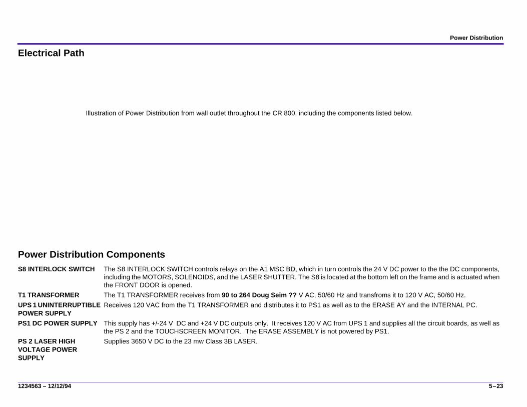
Electrical Path
Power Distribution ComponentsS8 INTERLOCK SWITCH The S8 INTERLOCK SWITCH controls relays on the A1 MSC BD, which in turn controls the 24 V DC power to the the DC components,
including the MOTORS, SOLENOIDS, and the LASER SHUTTER. The S8 is located at the bottom left on the frame and is actuated when the FRONT DOOR is opened.
T1 TRANSFORMER The T1 TRANSFORMER receives from 90 to 264 Doug Seim ?? V AC, 50/60 Hz and transfroms it to 120 V AC, 50/60 Hz.UPS 1 UNINTERRUPTIBLE POWER SUPPLY
Receives 120 VAC from the T1 TRANSFORMER and distributes it to PS1 as well as to the ERASE AY and the INTERNAL PC.
PS1 DC POWER SUPPLY This supply has +/-24 V DC and +24 V DC outputs only. It receives 120 V AC from UPS 1 and supplies all the circuit boards, as well as the PS 2 and the TOUCHSCREEN MONITOR. The ERASE ASSEMBLY is not powered by PS1.
PS 2 LASER HIGH VOLTAGE POWER SUPPLY
Supplies 3650 V DC to the 23 mw Class 3B LASER.
Illustration of Power Distribution from wall outlet throughout the CR 800, including the components listed below.

6–24 12/12/94 – 1234563
Section 6: Logic and Control
Diagram
Communication??is there anything I should say here??

Logic and Control
1234563 – 12/12/94 6–25
Circuit Boards (BDs)A1 MOTION SYSTEM CONTROL (MSC BD)
The A1 MSC BD is responsible for controlling the electro-mechanical devices in the CR 800 System. The primary functions include:• Controlling/restricting motion of the CASSETTE• Controlling the extraction and re-insertion of the PLATE from/into the CASSETTE.• Controlling the slow scan movement of the PLATE during scanning.• Controlling the motion of the PLATE into and out of the erase position.• Controlling the ERASE LAMPS.• Controlling motion of the DUPLEX CAM
A2 MASTER CENTRAL PROCESSING UNIT (MCPU BD)
The primary functions of the A2 MCPU BD include: • Acquiring raw image and laser reference data from the A3 Digitizer BD.• Converting the image data from 16 bit linear to 12 bit log.• Uses the Laser Reference data to adjust the image.• Performing a colletor profile correction on the image data.• Sending the image to the INTERNAL PC for image processing and viewing.• Initializing the A3 DIGITIZER BD and the A4 GALVO BD with the scan parameters based on the PLATE size to be scanned.• Keeping track of the maximum pixel value of a current scan so that the “smart erase” algorithm can calculate the erase time for that
PLATE.A3 MICRO COMPUTED RADIOGRAPHY DIGITIZER CONTROLLER (DIGITIZER BD)
The A3 DIGITIZER BD is primarily responsible for acquiring laser reference and image data from the A5 PMT/DAS BD and setting up timing and control to the A5 PMT/DAS and A4 GALVO BDs, including:
• Synchronizing the start and sweep of the GALVO Fast Scan and the PMT/DAS data acquisition A/D converters.• Receiving image and reference data one pixel at at time (actually in 32 bit segments, half image and half reference data that
comprise 1 pixel) from the A5 PMT/DAS BD and loading it into a FIFO (First In/First Out) memory location until a line has been accumulated.
• Triggering DMA (Direct Memory Access) transfer of the image data from the FIFO to the A2 MCPU BD when each line is complete.A4 GALVO BD The A4 GALVO BD provides drive and feedback signals to control the position of the MIRROR on the GALVO that deflects the laser
beam onto the PLATE during the fast scan operation. The A3 DIGITIZER BD sends data to the A4 board then sends timing signals used by the logic on the A4 board to command the GALVO to move the MIRROR through a full line cycle. At the end of the cycle the A4 board sends a signal to the A3 board to indicate that the line has been completed. A closed loop servo circuit n the A4 uses the position sensors in the GALVO to keep the MIRROR velocity smooth and in the commanded position for good image quality.
A5 PHOTOMULTIPLIER/DATA ACQUISITION SYSTEM (PMT/DAS BD)
The A5 PMT/DAS BD amplifies, sums, and filters the PMT outputs, then does the A/D conversion.

6–26 12/12/94 – 1234563
M1 CAM MOTOR See “Cassette Handling / Plate Handling.”The M1 is a brush type DC motor. Its function is to drive the DUPLEX CAM . It responds to commands from the MCPU to index the DUPLEX CAM to each of the 4 CAM positions, Home (1), Pinch (2), Clamp (3), Pinch/Latch (4).
M2 LEFT and M3 RIGHT CASSETTE DRIVE MOTORsThese 2 MOTORS are used to load and unload the CASSETTE from the Load Station, running in both Load (forward) and Unload (reverse) directions. They are controlled by the MSC which receives commands from the MCPU to load and unload the CASSETTE.
A6 SLOW SCAN CONTROLLER (SSC BD)
The A6 SLOW SCAN CONTROLLER BD is a microprocessor controlled circuit board that controls the operation of the SLOW SCAN MOTOR. The A6 is responsible for accurately controlling all vertical movement of the PLATE in a constant linear motion perpendicular to the direction of the LASER sweep. The A6 communicates with the A1 MSC via an RS-232 serial link. It connects to the COIL BOARD in the SLOW SCAN MOTOR to drive the COILS and read the HALL EFFECT SENSORS. It also connects to the ENCODER at the bottom of the SLOW SCAN MOTOR ASSEMBLY. See “A7 COIL BD Operation.”
A7 COIL BD The A7 COIL BD is an integral component of the SLOW SCAN MOTOR. Six identical triangular shaped coils of wire are located on the surface of the A7 BD. The coils are arranged around the central shaft of the SLOW SCAN MOTOR. At the outer edge of the coils are 3 Hall Effect Sensors. See “A7 COIL BD Operation.” for a description of the operation of the A7 COIL BD.
A8 CAM SENSOR (CAM BD) The A8 CAM SENSOR BD reads the position of the DUPLEX CAM based on whether the CAM FLAGS are blocked or unblocked. It then reports the position to the MSC which directs the next movement of the DUPLEX CAM based on the current status.See “Cassette Handling / Plate Handling.”
A9 LASER REFERENCE (REF BD)
The A9 is a small BD whose function is to sample a percentage of the laser signal as it leaves the LASER. For each pixel captured, there is both image data and corresponding laser reference data. The laser reference data is a measure of the laser power at the instant the image data was read.

Cassette Handling / Plate Handling
1234563 – 12/12/94 7–27
Section 7: Cassette Handling / Plate Handling
Function
The function of Cassette Handling is to move the CASSETTE into position in the CR 800 so that the PLATE can be extracted for scanning. Plate Handling involves unlatching the PLATE and hooking it onto the EXTRACTION BAR. After the scan is completed the PLATE is reinserted into the CASSETTE and the CASSETTE is transported to the CASSETTE LOADING STATION so that it can be removed by the Operator.
SLED PLATE Several switches, motors, sensors and other components are mounted to the top of the SLED PLATE. When the SLED PLATE moves forward and rearward in response to the indexing of the DUPLEX CAM, these components initiate various Cassette handling funcitons. A number of CAM FOLLOWERS, attached to the underside of the SLED PLATE engage stationary components on the INTERMEDIATE PLATE to actuate the various operations of Cassette Handling.
INTERMEDIATE PLATE The INTERMEDIATE PLATE, is a stationary plate, mounted beneath the SLED PLATE. Several components, mounted on the top surface of the INTERMEDIATE PLATE provide the position and direction for the movements of the components on theSLED PLATE as it moves forward and backward during the CASSETTE loading and unloading operations.
Illustration of the Cassette Handling Sub assembly, with callouts to the variouscomponents that would follow.

7–28 12/12/94 – 1234563
DUPLEX CAM and Related ComponentsThe unique design of the DUPLEX CAM enables a single mechanical component to actuate many movements in theCASSETTTE and PLATE handling sequence of operations. The DUPLEX CAM is essentially 2 CAMS, the SLED CAM and the HOOK CAM, each with separate functions.
Right facing view of DUPLEX CAMalso SLED CAM FOLLOWER.
CAM MOTOR
SLED CAM Formed by the groove cut into the right-facing side of the DUPLEX CAM. As the DUPLEX CAM rotates a SLED CAM FOLLOWER engages the SLED CAM, executing the movements associated with loading and unloading the CASSETTE.
HOOK CAM Formed by the outside shape of the DUPLEX CAM. As the DUPLEX CAM rotates, the HOOK CAM interacts with components that cause the PLATE to latch and unlatch and to be hooked and unhooked by the EXTRACTION BAR.
DUPLEX CAM positionsUse J. Bailey’s VISIO ill.
M1 CAM MOTOR Mounted on the left-facing side of the DUPLEX CAM, the CAM MOTOR is controlled by the MSC which directs it to index the DUPLEX CAM to each of its 4 positions based on feedback from the S10 and S11 SENSORS.
Ring flags: HOME FLAG POSITION FLAG
These 2 ring flags are mounted on the left-facing side of the DUPLEX CAM. Their function is to block and unblock the S10 and S11 SENSORS as the DUPLEX CAM rotates.
S10, S11 SENSORS
These 2 SENSORS are mounted on a common BD near the CAM MOTOR. As the DUPLEX CAM indexes to each of 4 positions, the RING FLAGS either block or unblock the beam of the S10 and S11 SENSORS. The status of the SENSORS is reported to the MSC,which then initiates the movement of the DUPLEX CAM to the next position.

Cassette Handling / Plate Handling
1234563 – 12/12/94 7–29
Index Positions of the DUPLEX CAM
The position of the DUPLEX CAM is verified by reading the S10 and S11 SENSOR status after a move. After the position is verified,the MSC BD directs the CAM MOTOR to index the DUPLEX CAM to the next position.
four CAM positions from M. Poccia’s .DWG file.
7–30 12/12/94 – 1234563
Cassette Handling Sensors
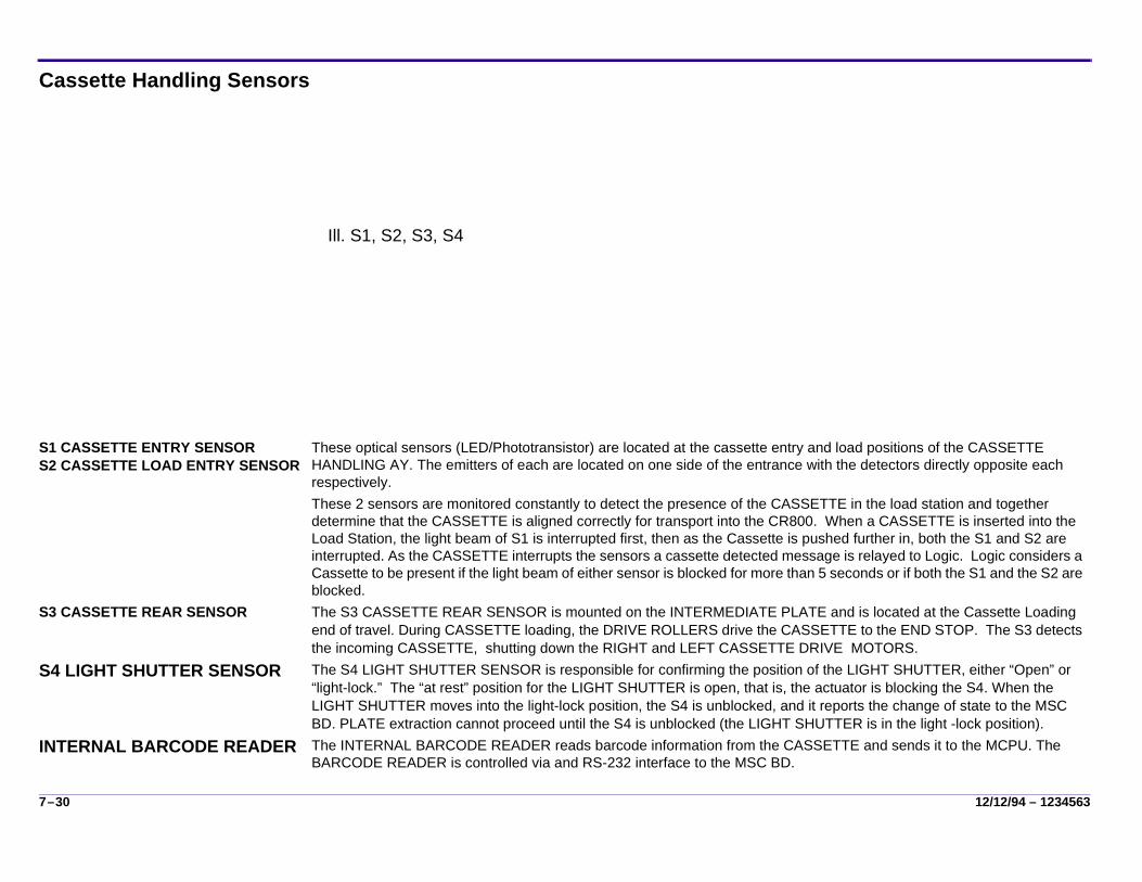
S1 CASSETTE ENTRY SENSORS2 CASSETTE LOAD ENTRY SENSOR
These optical sensors (LED/Phototransistor) are located at the cassette entry and load positions of the CASSETTE HANDLING AY. The emitters of each are located on one side of the entrance with the detectors directly opposite each respectively.These 2 sensors are monitored constantly to detect the presence of the CASSETTE in the load station and together determine that the CASSETTE is aligned correctly for transport into the CR800. When a CASSETTE is inserted into the Load Station, the light beam of S1 is interrupted first, then as the Cassette is pushed further in, both the S1 and S2 are interrupted. As the CASSETTE interrupts the sensors a cassette detected message is relayed to Logic. Logic considers a Cassette to be present if the light beam of either sensor is blocked for more than 5 seconds or if both the S1 and the S2 are blocked.
S3 CASSETTE REAR SENSOR The S3 CASSETTE REAR SENSOR is mounted on the INTERMEDIATE PLATE and is located at the Cassette Loading end of travel. During CASSETTE loading, the DRIVE ROLLERS drive the CASSETTE to the END STOP. The S3 detects the incoming CASSETTE, shutting down the RIGHT and LEFT CASSETTE DRIVE MOTORS.
S4 LIGHT SHUTTER SENSOR The S4 LIGHT SHUTTER SENSOR is responsible for confirming the position of the LIGHT SHUTTER, either “Open” or “light-lock.” The “at rest” position for the LIGHT SHUTTER is open, that is, the actuator is blocking the S4. When the LIGHT SHUTTER moves into the light-lock position, the S4 is unblocked, and it reports the change of state to the MSC BD. PLATE extraction cannot proceed until the S4 is unblocked (the LIGHT SHUTTER is in the light -lock position).
INTERNAL BARCODE READER The INTERNAL BARCODE READER reads barcode information from the CASSETTE and sends it to the MCPU. The BARCODE READER is controlled via and RS-232 interface to the MSC BD.
Ill. S1, S2, S3, S4

Cassette Handling / Plate Handling
1234563 – 12/12/94 7–31
CASSETTE Transport Components
LEFT FRONT ROLLER AYRIGHT FRONT ROLLER AY
The LEFT and RIGHT FRONT DRIVE ROLLER AYs each consist of 3 ROLLERS, mounted on a SHAFT. The RIGHT ROLLER AY is stationary, whereas the LEFT ROLLER AY is moveable. The top 2 rollers of both assemblies are made of soft plastic. The bottom left ROLLER is a plastic of medium hardness and the bottom right ROLLER is a very hard plastic.When the CASSETTE is loaded, it is pinched by the left and right FRONT ROLLERS as the CASSETTE DRIVE MOTORS move it toward the rear of the CR 800. Once the CASSETTE reaches the END STOP, the CASSETTE is clamped tightly between the medium and hard bottom ROLLERS to ensure that it will remain stationary while the PLATE is removed.
LEFT MIDDLE ROLLER AYRIGHT MIDDLE ROLLER AY
The 2 MIDDLE DRIVE ROLLER AYs (left and right) function exactly the same as the FRONT ROLLER ASSEMBLIES except that they are activated by the L3 MIDDLE ROLLER SOLENOID whenever a CASSETTE smaller than 35 x 35 cm is inserted into the CR 800.
LEFT REAR ROLLER AYRIGHT REAR ROLLER AY
Each of the REAR ROLLER AYs has a top and bottom ROLLER. Both top ROLLERS and the bottom left ROLLER are medium hardness while the bottom right ROLLER is very hard. When the DRIVE ROLLERS drive the CASSETTE into position at the end stop, the CASSETTE is firmly wedged between the 2 bottom ROLLERS, ensuring that the CASSETTE will remain stationary while the PLATE is removed and reinserted.
L3 MIDDLE ROLLER SOLENOID When the L3 MIDDLE ROLLER SOLENOID is energized, it prevents the MIDDLE DRIVE ROLLER from moving to the clamp position.
M2 LEFT CASSETTE DRIVE MOTORM3 RIGHT CASSETTE DRIVE MOTOR
After the system has detected and affirmed that a CASSETTE is ready to be loaded, the MSC directs the 2 CASSETTE DRIVE MOTORS to start. They drive the TIMING BELT, which drives the DRIVE ROLLERS.

7–32 12/12/94 – 1234563
PLATE Handling Components
HOOKING the PLATE to the EXTRACTION BAR1. As the DUPLEX CAM rotates from position 1 toward position 2, the HOOK
CAM pushes down on the HOOK CAM FOLLOWER.2. The HOOK YOKE FOLLOWER pushes down on the HOOK YOKE AY,
forcing the HOOK YOKE WHEELS to push down on the HOOK YOKE LEVERS of the EXTRACTION BAR.
3. The EXTRACTION BAR HOOKS move up into the 2 holes in the latched PLATE.
4. As the DUPLEX CAM indexes all the way to position 2, the SPRINGS inside the PLATE unlatch the PLATE from the CASSETTE SHELL.
5. The HOOKS, which are spring loaded, then grab the PLATE and hook it tightly to the EXTRACTION BAR.
6. The EXTRACTION BAR holds the PLATE firmly as it is extracted from the CASSETTE, moved through the scan/erase operation, and reinserted into the CASSETTE SHELL.
7. When the PLATE is reinserted, the DUPLEX CAM rotates to positions 3 and 4, releasing the HOOKS are latching the PLATE is inside the CASSETTE SHELL.
Hook yoke ay and extraction bar
ACTION OF THE HOOKS IN SIDE THE CASSETTE/PLATE
HOOK CAM The HOOK CAM is formed by the outer rim of the DUPLEX CAM. As the DUPLEX CAM indexes through the positions 1 - 4, the HOOK CAM initiates the actions for hooking and unhooking the PLATE to the EXTRACTION BAR .
HOOK YOKE AY The HOOK YOKE AY is responsible for unlatching the PLATE from the CASSETTE and hooking it to the EXTRACTION BAR.
EXTRACTION BAR The EXTRACTION BAR is a long metal bar attached at the top of the LEAD SCREW. As the LEAD SCREW turns, the EXTRACTION BAR moves up and down. Its function is to hook the PLATE firmly while it’s in the loaded CASSETTE, move the PLATE vertically through the scan/erase operation, and return it to the CASSETTE SHELL.

Cassette Handling / Plate Handling
1234563 – 12/12/94 7–33
Components for Guiding the PLATE
Plate Guide Ay
PLATE GUIDE AY The PLATE GUIDE ASSEMBLY functions to enable the EXTRATION BAR to pass when it moves up and down. In addition, the PLATE GUIDE AY has 2 sets of PLATE GUIDE ROLLERS that position the PLATE for optimal scanning.
PLATE GUIDE FINGERS
The function of these 2 spring-loaded PLATE GUIDE FINGERS (FRONT and REAR) is to guide the PLATE back into the CASSETTE SHELL.
S5 PLATE PRESENT SENSOR
After the PLATE has been hooked by the EXTRACTION BAR, it is pulled downward by the SLOW SCAN AY. The hooked PLATE passes between the emitter and detector of the S5 PLATE PRESENT SENSOR. The MSC BD reads the state of the S5 and determines if a P;ATE is present or not before continuing the slow scan operation.
8–34 12/12/94 – 1234563
Section 8: Scan/Erase Subsystem
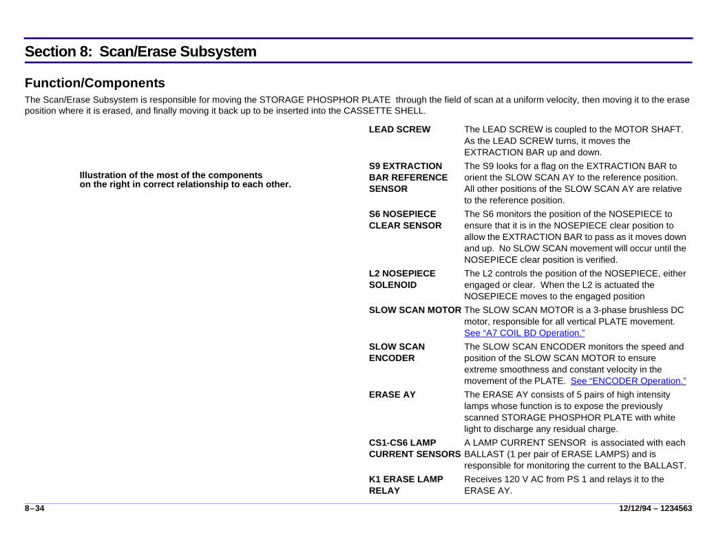
Function/ComponentsThe Scan/Erase Subsystem is responsible for moving the STORAGE PHOSPHOR PLATE through the field of scan at a uniform velocity, then moving it to the erase position where it is erased, and finally moving it back up to be inserted into the CASSETTE SHELL.
Illustration of the most of the componentson the right in correct relationship to each other.
LEAD SCREW The LEAD SCREW is coupled to the MOTOR SHAFT. As the LEAD SCREW turns, it moves the EXTRACTION BAR up and down.
S9 EXTRACTION BAR REFERENCE SENSOR
The S9 looks for a flag on the EXTRACTION BAR to orient the SLOW SCAN AY to the reference position. All other positions of the SLOW SCAN AY are relative to the reference position.
S6 NOSEPIECE CLEAR SENSOR
The S6 monitors the position of the NOSEPIECE to ensure that it is in the NOSEPIECE clear position to allow the EXTRACTION BAR to pass as it moves down and up. No SLOW SCAN movement will occur until the NOSEPIECE clear position is verified.
L2 NOSEPIECE SOLENOID
The L2 controls the position of the NOSEPIECE, either engaged or clear. When the L2 is actuated the NOSEPIECE moves to the engaged position
SLOW SCAN MOTOR The SLOW SCAN MOTOR is a 3-phase brushless DC motor, responsible for all vertical PLATE movement. See “A7 COIL BD Operation.”
SLOW SCAN ENCODER
The SLOW SCAN ENCODER monitors the speed and position of the SLOW SCAN MOTOR to ensure extreme smoothness and constant velocity in the movement of the PLATE. See “ENCODER Operation.”
ERASE AY The ERASE AY consists of 5 pairs of high intensity lamps whose function is to expose the previously scanned STORAGE PHOSPHOR PLATE with white light to discharge any residual charge.
CS1-CS6 LAMP CURRENT SENSORS
A LAMP CURRENT SENSOR is associated with each BALLAST (1 per pair of ERASE LAMPS) and is responsible for monitoring the current to the BALLAST.
K1 ERASE LAMP RELAY
Receives 120 V AC from PS 1 and relays it to the ERASE AY.

Scan/Erase Subsystem
1234563 – 12/12/94 8–35
Scan/Erase PositionsThere are 4 distinct vertical positions of the EXTRACTION BAR. These positions are monitored by the S9 REFERENCE SENSOR and by ENCODER COUNTS that are defined when the system is set up at the factory. .
ILlustration of Slow Scan / Reference positions
REFERENCE SENSOR Position
Position of the EXTRACTION BAR when the S9 REFERENCE SENSOR is blocked. The REFERENCE SENSOR position is factory set and varies among machines. When the system is initialized, the EXTRACTION BAR looks for the S9. Once it is located, the EXTRACTION BAR moves up to the home position where it remains until the start of a new cycle. See “Initialization.”
Home Position Position of the EXTRACTION BAR at the start and end of a cycle. Home position is between 3.8 and 4.5 cm (1.5 and 1.75 in.) above the REFERENCE POSITION SENSOR. The home position is factory set; however, it can be adjusted in the field if necessary.
Start of Scan Position
Position in the vertical movement of the EXTRACTION BAR when the NOSEPIECE is engaged, as detected by the L1 NOSEPIECE CLEAR SENSOR, and the PLATE is in position to be scanned. Start of scan is a predefined number of encoder counts below home position. This defines the mechanical start of scan and differs from the Optical start of scan which occurs after the MCPU tells the GALVO to begin scanning the PLATE.The end of scan is defined by encoder counts based on the PLATE size.
Erase Position A position below the End of Scan where the PLATE is centered in front of the ERASE LAMPS. The position varies depending on PLATE size.

8–36 12/12/94 – 1234563
Slow Scan OperationThree main components are involved in SLOW SCAN operation:
• A6 SLOW SCAN CONTROLLER BD• SLOW SCAN MOTOR, including
– STEEL PLATE, which works with the A7 COIL BD to generate the magnet which creates torque in the MOTOR.
– A7 COIL BD, which maintains the correct rotation of the SLOW SCAN MOTOR. See “A7 COIL BD Operation.”
– MAGNET/FLYWHEEL. The FLYWHEEL is a heavy steel cylinder used to add rotating mass to the MOTOR and smoot out its rotation. At the upper end of the cylinder is a very strong MAGNET.
• ENCODER, which monitors the speed and position of the MAGNET in its rotation to ensure extreme smoothness and constant velocity. See “ENCODER Operation.”
Function of the A 6SLOW SCAN CONTROLLER BDThe A6 SLOW SCAN CONTROLLER BD is programmed to perform predefined movements of the SLOW SCAN MOTOR. The A7 COIL BD and the ENCODER are cabled directly to the A6 CONTROLLER.Typically the parameters of a movement include:
• Which direction (clockwise or counter-clockwise) the MOTOR will move.• How many encoder counts the MOTOR must move.• How fast the MOTOR must accelerate.• What speed the MOTOR must run.• How fast the MOTOR must de-celerate.
Illustration of Basic Slow Scan subsystem components
Scan/Erase Subsystem
1234563 – 12/12/94 8–37
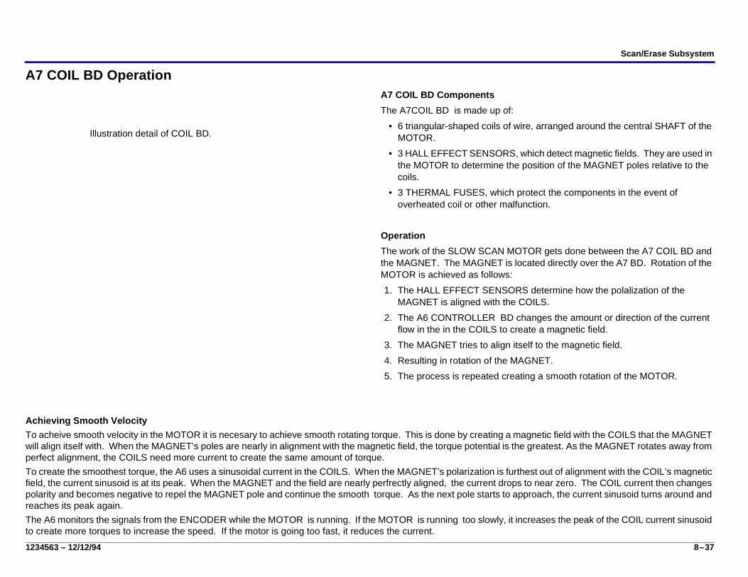
A7 COIL BD OperationA7 COIL BD ComponentsThe A7COIL BD is made up of:
• 6 triangular-shaped coils of wire, arranged around the central SHAFT of the MOTOR.
• 3 HALL EFFECT SENSORS, which detect magnetic fields. They are used in the MOTOR to determine the position of the MAGNET poles relative to the coils.
• 3 THERMAL FUSES, which protect the components in the event of overheated coil or other malfunction.
OperationThe work of the SLOW SCAN MOTOR gets done between the A7 COIL BD and the MAGNET. The MAGNET is located directly over the A7 BD. Rotation of the MOTOR is achieved as follows:1. The HALL EFFECT SENSORS determine how the polalization of the
MAGNET is aligned with the COILS.2. The A6 CONTROLLER BD changes the amount or direction of the current
flow in the in the COILS to create a magnetic field.3. The MAGNET tries to align itself to the magnetic field.4. Resulting in rotation of the MAGNET.5. The process is repeated creating a smooth rotation of the MOTOR.
Achieving Smooth VelocityTo acheive smooth velocity in the MOTOR it is necesary to achieve smooth rotating torque. This is done by creating a magnetic field with the COILS that the MAGNET will align itself with. When the MAGNET’s poles are nearly in alignment with the magnetic field, the torque potential is the greatest. As the MAGNET rotates away from perfect alignment, the COILS need more current to create the same amount of torque. To create the smoothest torque, the A6 uses a sinusoidal current in the COILS. When the MAGNET’s polarization is furthest out of alignment with the COIL’s magnetic field, the current sinusoid is at its peak. When the MAGNET and the field are nearly perfrectly aligned, the current drops to near zero. The COIL current then changes polarity and becomes negative to repel the MAGNET pole and continue the smooth torque. As the next pole starts to approach, the current sinusoid turns around and reaches its peak again.The A6 monitors the signals from the ENCODER while the MOTOR is running. If the MOTOR is running too slowly, it increases the peak of the COIL current sinusoid to create more torques to increase the speed. If the motor is going too fast, it reduces the current.
Illustration detail of COIL BD.

8–38 12/12/94 – 1234563
ENCODER OperationThe ENCODER monitors the speed and position of the MAGNET in its rotation to ensure extreme smoothness and constant velocity. The ENCODER is made up of:
• ENCODER WHEEL, which is a clear disk that has been printed with 5000 lines leading from the center to the outer edge.
• The 2 OPTICAL SENSORS, which are placed at the edge of the ENCODER WHEEL so that the beam of each is interrupted by the printed lines as the WHEEL rotates.
The sensors are placed so that their signals are nominally 90 degrees out of phase with each other in a “quadrature relationship”: One detector looks at the edge of a line while the other looks in the middle of the line. The speed of the SLOW SCAN MOTOR is determined by measuring the frequency of the signals. The direction of the rotation is determined by the sequence in which the signals change.The feedback from the 2 sensors is constantly monitored by the A6 SLOW SCAN CONTROLLER BD, and the current to the COIL BD is reduced or increased to ensure smooth rotation and constant velocity.Each rotation of the LEAD SCREW equals 20,000 encoder counts. The system drives to each of the soft positions (start of scan, erase, and end of scan) until it reaches the correct number of counts.
Illustration - detail of encoder wheel.
Illustration - detail of encoder signals.
OPTICAL Subsystem
1234563 – 12/12/94 9–39
Section 9: OPTICAL Subsystem
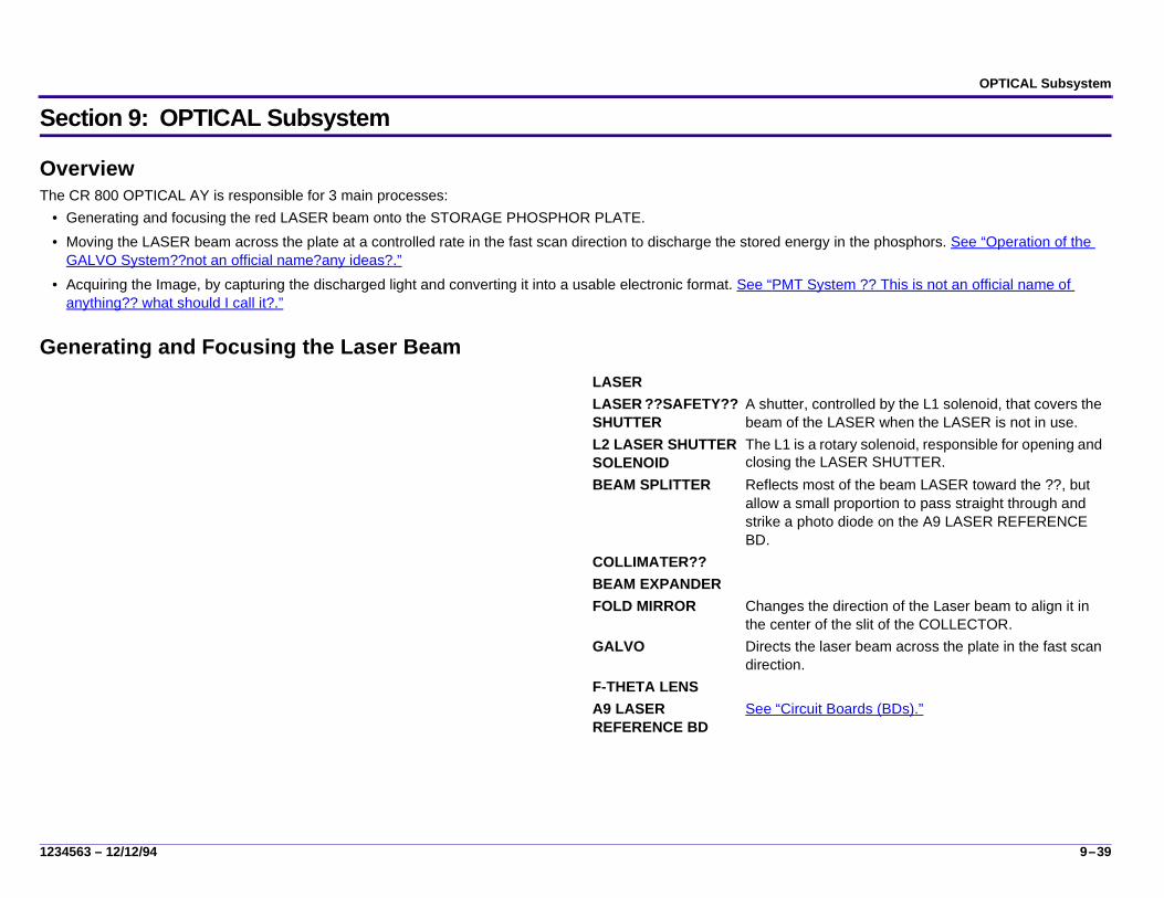
OverviewThe CR 800 OPTICAL AY is responsible for 3 main processes:
• Generating and focusing the red LASER beam onto the STORAGE PHOSPHOR PLATE.• Moving the LASER beam across the plate at a controlled rate in the fast scan direction to discharge the stored energy in the phosphors. See “Operation of the
GALVO System??not an official name?any ideas?.” • Acquiring the Image, by capturing the discharged light and converting it into a usable electronic format. See “PMT System ?? This is not an official name of
anything?? what should I call it?.”
Generating and Focusing the Laser BeamLASERLASER ??SAFETY?? SHUTTER
A shutter, controlled by the L1 solenoid, that covers the beam of the LASER when the LASER is not in use.
L2 LASER SHUTTER SOLENOID
The L1 is a rotary solenoid, responsible for opening and closing the LASER SHUTTER.
BEAM SPLITTER Reflects most of the beam LASER toward the ??, but allow a small proportion to pass straight through and strike a photo diode on the A9 LASER REFERENCE BD.
COLLIMATER??BEAM EXPANDERFOLD MIRROR Changes the direction of the Laser beam to align it in
the center of the slit of the COLLECTOR.GALVO Directs the laser beam across the plate in the fast scan
direction. F-THETA LENSA9 LASER REFERENCE BD
See “Circuit Boards (BDs).”

9–40 12/12/94 – 1234563
Operation of the GALVO System??not an official name?any ideas?The main purpose of the GALVO system is to rotate a mirror to cause the beam of the LASER to scan across the PHOSPHOR PLATE (fast scan), do a quick retrace, and scan another line until the entire plate has been scanned.In its simplest form, the operation of the GALVO system is a feedback system in which the desired position of the GALVO ??SHAFT, MIRROR ?? is compared to its actual position in the rotation??motion??, and corrections are made to keep the GALVO, hence the beam of the LASER, focused on the exact spot of the STORAGE PHOSPHOR PLATE at the expected time.
Simple block diagram of the Digitizer BD, inputs to the GALVO the GALVO and the deflected beam of the LASER on a target (PLATE)
A3 DIGITIZER BD The DIGITIZER BD is a key player in that it controls the operation of the GALVO BD to sweep the beam of the LASER as well as the PMT/DAS BD to collect the image data off the scanned PHOSPHOR PLATE.
GALVO The GALVO consists of a motor that rotates a SHAFT with a MIRROR at the end that deflects the beam of the LASER onto the PHOSPHOR PLATE.
A4 GALVO BD The GALVO BD contains an extremely accurate feedback circuit for controlling the position of the MIRROR ?OR SHAFT?, hence the beam of the LASER. Inputs to the GALVO BD which define the desired position of the MIRROR include:
• Clock signal from the DIGITIZER BD which starts, continues, and stops a 13 bit counter that keeps track of the ????.
• Current PLATE size from the DIGITIZER BD (per the barcode on the PLATE).
• Offset (start) and amplitude (how far) values for the particular PLATE size, which were set up in calibration.
Input from position sensors determine exactly where in the sweep the GALVO SHAFT is, the actual position.The actual position is compared to the desired position and any error is corrected for to ensure a smooth sweep of the beam.Output of the GALVO BD are line start signals to the DIGITIZER BD to say that a line is complete and it is able to start another.

OPTICAL Subsystem
1234563 – 12/12/94 9–41
Detailed Operation of the A4 GALVO BD??All apologies to Doug. Below is an attempt to provide a more detailed description, but to make it less technical. I don’t know how well I’ve succeeded.
1. To set up for a PLATE scan, the system (WHAT?) sets the plate-size-select inputs to the State Machine for the PLATE being scanned, that is, the plate width and the number of lines to be scanned ?? is this true?.
2. It then writes the values for that plate size, which were set up in calibration to the Offset and Amplitude D/A Converters. The values loaded will vary from machine to machine (??why?). What are these values, do the values include the # of pixels plus the dwell time and the ramp up??
3. When the Galvo Clock starts running, the 13 bit counter starts counting up and sends the current value of the count to the State Machine.
4. As the count progresses, the State Machine outputs a 12 bit value indicating the desired current position of the GALVO between the beginning and end of the scan line, as defined by the offset and amplitude signals. See ?? signal?? what should I call this??
5. The Closed-Loop Servo Circuit receives input about:a. The desired GALVO ??shaft, mirror??position from the State Machineb. The actual GALVO position which is derived from signals of the Galvo-
Position-Sensors. 6. The Servo Circuit compares the Desired Galvo Position against the Actual
Galvo Position. The resulting error (difference) is combined with the Desired Galvo Position to determine the amount of current that is delivered to the GALVO coil. The more current that is passed through the coil, the further the GALVO will turn the MIRROR.
7. At the end of the cycle (which includes ramp up, trace, retrace, dwell time??), a. the State Machine sends a line-start signal back to the DIGITIZER BD to
indicate that the full GALVO sweep is complete for that line and it is ready to start another one.
b. At the same time, the counter-reset signal ?pulses? to set the 13 bit counter back to “0” zero. If the Galvo Clock continues to run, the cycle will continue and another sweep of the GALVO will begin. This will continue until all the lines are read ?? how does it know how many??
This illustration is a more detailed block diagram, but not as complex as Doug’s. It will, I hope, include all that is useful, but no more than isuseful to describe the function of the A4.

9–42 12/12/94 – 1234563
Desired Position Signal - Velocity vs. Time
This will be a chart showing the signal both time and velocity. I need help here, both in drawing it, and in any textthat should accompany the graphical representation.
This is a pretty bad drawing program, but it isjust to give you an idea. Mike Mesiti will do a better job once we give him the input.

OPTICAL Subsystem
1234563 – 12/12/94 9–43
PMT System ?? This is not an official name of anything?? what should I call it?The purpose of the PMT system is to collect the blue light emitted from the PHOSPHOR PLATE when the PLATE is scanned, measure its intensity, and convert the measurement to digital format. Importantly, the power of the LASER is measured at the exact instant that the blue light is measured. These 2 measurements eventually make up the??? of the digital signal for ???Components
Possibly the same or similar illustration from the CR Theory section or an illustration of the collector, nose piece, and PMTs.
A3 DIGITIZER BD While not truly a component of the PMT System, the A3 controls the operation of the GALVO BD and the A5 PMT/DAS BD to coordinate the measurement and collection of image data. As the A3 commands the GALVO to turn the MIRROR to sweep the beam of the LASER across the PLATE, it also commands the PMT/DAS BD to make measurement of the emitted light at precisely controlled intervals. Each measurement results in a pixel in the final collected image.
LIGHT COLLECTOR and NOSEPIECE
These components collect the blue light emitted from the PLATE and direct it toward the PMT TUBE. All of the inside surfaces of both components are reflective.
PHOTOMULTIPLIERTUBE (PMT)
There are 5 PMTs in the CR 800. Each is an extremely sensitive light sensor, which produces a current signal in proportion to the light striking its face. The PMT uses a high voltage power source to operate, and the sensitivity of the PMT varies with the voltage of he power source.
A5 PMT/DAS BD The PMT/DAS BD amplifies the signals from the 5 PMTs, adds them together, filters the summed signal, then converts it to a digital format in an A/D Converter. The PMT/DAS BD also measures the strength of the beam of the LASER and converts it to digital format in a separate A/D converter.
A9 LASER REFERENCE BD

9–44 12/12/94 – 1234563
Operation of the PMT SystemCollecting the Blue LightWhen the red beam of the LASER strikes the PLATE, blue light is emitted in random directions. The COLLECTOR and NOSEPIECE are designed to capture as many of the rays of blue light as possible and direct them toward the face of the PMTs. Some of the red laser light striking the PHOSPHOR PLATE is reflected and enters the COLLECTOR as well. Between the COLLECTOR and the PMTs is a BLUE FILTER, which rejects most of the red light and passes most of the blue light so that the PMTs see only the blue light from the PHOSPHOR PLATE.Converting the Blue Light to Electrical CurrentInside the PMT are a number of elements that are connected to varying levels of high voltage. The circuitry on the PMT/DAS BD divides the high voltage into a descending series of voltages. These voltages are connected to various structures within the PMT. In the illustration, example voltages are given to illustrate the process.The high voltage power supply actually produces a high negative voltage. The PHOTOCATHODE is connected directly to the -600 volt source. The next structure inside the PMT is the FOCUSING ELECTRODE, which is set to - 500 Volts. Further in are a series of DYNODES, which are set at decreasing voltages until at the very end is an ANODE which is set at 0 volts. The PHOTOCATHODE is made of a material that will emit an electron when it is hit by a light photon. However, since the efficiency of the PHOTOCATHODE is less than 100% the number of electrons will not be equal to the number of incoming photons. The negatively charged electron is influenced by the electric field that exists between the PHOTOCAHTODE (at -600 V) and the more positive FOCUSING ELECTRODE (at -500 V); therefore the electron is drawn toward the FOCUSING ELECTRODE.As it nears the FOCUSING ELECRODE, it is further drawn by the even more positive DYNODE. At each DYNODE, the number of electrons increases so that as the process continues, more and more electrons are added and all the electrons are attracted to the next more positive DYNODE. At the end of the PMT, all the electrons are attracted the ANODE which collects the electrons and sends them to the PMT/DAS BD as a small current signal.
Collecting the blue light; overview, fig. 1 from Doug’s drawing.
Converting the blue light; PMT Internal detail from Do ug’s drawing, fig. 2

OPTICAL Subsystem
1234563 – 12/12/94 9–45
Operation of the PMT/DAS BD
1. The 5 PMT Tubes plug into the PMT/DAS BD itself. The HIGH VOLTAGE POWER SUPPLY feeds power to the HIGH VOLTAGE DIVIDERS. Each PMT has its own HIGH VOLTAGE DIVIDER whose function is to send the particular high voltage levels to the structures inside the PMTs.
2. The ANODE of each PMT is connected to an individual CURRENT TO VOLTAGE AMPLIFIER, which turns the small current signal from each PMT into a proportional voltage signal. Each of the voltage signals goes through a PMT GAIN CONTROL D/A CONVERTER. These converters act like volume controls so we can adjust the signal level coming from each PMT in order to account for gain variances from PMT to PMT.
3. The corrected signals are added together in the SUMMING AMPLIFIER. An OFFSET ADJUSTMENT SIGNAL is added in to “tune out” any “dark current” that may have accumulated and to compensate for any other offset error in the electronics. The offset signal comes from a pair of D/A CONVERTERS that allow coarse and fine adjustments.
4. The summed signal is then sent through a LOW PASS FILTER for noise reduction.??do we need the sampling theory stuff here??
This will be some subsample of the PMT/DAS BD block diagram from D. Seim. I’mnot sure how to simplify this and get the important details for this audience. Same problem with the Galvo Bd.
Also, I’m not sure how much of Doug’s explanation to include. Therefore, I’m putting almost all of the text in below and we can talk about how or if it needs to be simplified (rewritten).HMB

9–46 12/12/94 – 1234563
5. The filtered signal is then set to the 16 BIT A/D CONVERTER for measurement. This is the measurement of the intensity of the blue light that was emitted by the PHOSPHOR PLATE.
6. Recall that the intensity of the blue light is proportional to the charge stored by the phosphor and the intensity of the laser beam that struck the phosphor. In order to reconstruct the original image, we need to know how strong the laser beam was when the blue light was measured. Because Helium Neon Lasers are noisy, we must make a measurement and compensate on a pixel by pixel basis.
7. Recall that a small portion of the beam of the LASER was sent to a photo diode on the LASER REFERENCE BD. The photo diode creates a small current signal in proportion to the power of the beam of the LASER. This signal is amplified by a CURRENT TO VOLTAGE AMPLIFIER on the PMT/DAS BD to make voltage signal in proportion to the power of the LASER. ?need to say something about it being at the exact time??. This signal is also filtered and then converted to digital format by a 16 BIT A/D CONVERTER.
8. ?? Boy do I need help here?? The PMT/das BD contains logic circuits necessary to interface to the DIGITIZER BD. The Interface includes a very simple serial data interface to allow the DIGITIZER BD to adjust the various D/A CONVERTERS on the BD (?on the PMT/DAS BD?). The PIXEL CLOCK ?? (is this the GALVO CLOCK?If not what?) goes to both of the A/D CONVERTERS and commands them to perform a measurement, and each CONVERTER produces a 16 bit value for each measurement. The two 16 bit values go to a DATA MULTIPLEXER that splits the two 16 bit values into 8 bit chunks.
9. Upon request, the combined image and reference data is sent to the DIGITIZER BD one pixel at a time.

Error and Activity Logs
1234563 – 12/12/94 10–47
Section 10: Error and Activity Logs
The CR 800 logs error, activity, and actuation information. All logs are created on the INTERNAL PC. They are time stamped, written in English, and can be accessed from a remote location by authorized Service Personnel.?Maybe this is superfluous since there is more and better information in diagnostics?? Should it just be eliminated?
Error Reporting / LogsThere are essentially 2 kinds of errors reported by the system, errors that the user can do something about and errors that provide information to or require the action of a Service Provider.Error Messages (User Correctable)
• Error messages, along with associated error codes, are displayed on the TOUCHSCREEN whenever there is a specific action that the user can perform to correct a problem.
• An Error Message will also be displayed if there is danger of critical data being altered or deleted.
• The Error Message provides clear instruction as to the actions the User must perform before resuming operation.
• These error codes and messages are logged along with other Error Codes with the same sorting capabilities. ??is this true or is there a separate file?/
Error History / Frequency• Errors that cannot be corrected by the user, display only the Error Code on the TOUCHSCREEN. • These errors, of a system or fatal nature, are logged in the Error History Log ??name?? and require the action of a Service Provider to clear the error. ?? I don;t
know if this is true??.• Each error is recorded in the error log and labeled with the:
– Actuation count– Date and time it was detected– Error Code
• The number of times each error has occurred is retained in the Frequency Log ?? is this true?? If so, what other information is in this log??• Actuation and Error Frequency counts are retained until they are cleared by a Service Provider. ?? Can these logs and reports be printed out??• Error History / Frequency Logs are accessible only by authorized Service Personnel.
Screen capture with error message

10–48 12/12/94 – 1234563
Activity LogsActivity Logs maintain a record of all system actuations (scan ?? what defines an actuation>??). These Logs are available to Key Operator Personnel and authorized Service Personnel. Activity logs can be sorted by Cassette ID, Date, Time, Technician ID, ???
• Count of all actuations. • Occurrences of images deleted prior to routing along with:
– Technician ID– Exam type – Cassette ID
• Record of the successful transmission of images to all destinations. The log contains the:– Time and date of the successful transmission– Identification of the image– Destination identifier
•

SEQUENCE OF OPERATIONS
1234563 – 12/12/94 11–49
Section 11: SEQUENCE OF OPERATIONS
Initialization?? THIS WILL COME FROM THE MEETING NOTES FROM DOUG SEIM.??
CASSETTE HANDLING / PLATE HandlingCASSETTE Handling involves two operations - loading the CASSETTE into the CR 800 and unloading the CASSETTE from the CR 800
CASSETTE Loading[1] Prior to loading a CASSETTE into the CR 800:
• The patient (P) and exam (E) data is entered into the system, either at the REMOTE OPERATIONS PANEL or at the TOUCH SCREEN on the CR 800. • The Operator scans the CASSETTE BARCODE and the CASSETTE information is added to the
[2] The CR 800 is ready to receive a CASSETTE for scanning. All initial conditions have been met.• The DUPLEX CAM is at Home position.
– LEFT ROLLER ASSEMBLIES (FRONT and MIDDLE) are retracted.– STOP PIN is in the closed position– LIGHT SHUTTER is unblocked
• All MOTORS are stopped.• EXTRACTION BAR is at Home position• NOSEPIECE is in the Clear position
[3] The Operator pushes the CASSETTE into the LOADING STATION until the CASSETTE reaches the STOP PIN.
[4] The CASSETTE ENTRY SENSOR, S1 and the CASSETTE LOAD SENSOR, S2 detect the presence of the CASSETTE in the LOAD STATION and that it is aligned correctly
NoteThe S1 and S2 are continually monitored by the MSC BD. A CASSETTE is considered present if at least one of the SENSORS is blocked for more that 5 seconds or if both S1 and S2 are blocked. The sequence continues only when both are blocked, otherwise and error message is reported.?? DID WE DECIDE TO PUT ERROR MESSAGE CODES IN THEORY??

11–50 12/12/94 – 1234563
[5] The INTERNAL BARCODE READER reads the CASSETTE size, speed, and serial number and:
• Issues an audible tone.• Sends:
– a “Cassette Detected” message to the MCPU.– the CASSETTE size (length and width) to the MCPU.
[6] The MCPU sends:• A “Cassette Detect” reply to the MSC, WHICH TELLS THE msc to stop
sending further requests to the MCPU.• a “Scan Request” to the INTERNAL PC.
[7] The INTERNAL PC: (a) Verifies that it has enough memory to receive an image.(b) Creates a RAW_IMAGE file to receive the image ?? is this a 10 mg.?
tIM HAS SUGGESTED THAT IT WILL VARY BASED ON PLATE SIZE?? ANY OTHER COMMENTS?
(c) Sends a “Scan Request” reply to the MCPU with a value of “OK”.[8] The MCPU:
(a) Notifies the MSC that it is OK to load the CASSETTE.(b) Sends the CASSETTE size and speed information to the DIGITIZER
BD.
NoteIf the barcode read failed, the data would be have to be keyed in and would come from the INTERNAL PC.
[9] The MSC executes the actions to index the SLED CAM, start the DRIVE MOTORS, M1 and M2, and in turn move the CASSETTE into the Load position ready to be clamped.

SEQUENCE OF OPERATIONS
1234563 – 12/12/94 11–51
[10] The SLED CAM indexes to position 2.(a) The SLED PLATE moves.250 in. forward.(b) If the CASSETTE is:
[11] The LEFT and RIGHT CASSETTE DRIVE MOTORS, M2 and M3, start, driving the TIMING BELTS which turn the DRIVE ROLLERS.
[12] The DRIVE ROLLERS drive the CASSETTE to the rear until it is detected by the CASSETTE REAR SENSOR, S3.
[13] Sensor S3, signals the MSC to shut off the DRIVE MOTORS.[14] The DRIVE MOTORS shut off. At this time the CASSETTE is wedged
securely between LEFT and RIGHT REAR ROLLER AYs.
CASSETTE Unloading*** the CASSETTE unloading steps go here***
35cm x 35cm 35cm x 43cm
The LEFT FRONT ROLLER AY moves to the right to Pinch position, which pinches the CASSETTE against the RIGHT FRONT ROLLER AY.
18cm x 24cm 24cm x 30cm
The L2, MIDDLE ROLLER SOLENOID actuates moving the LEFT MIDDLE ROLLER AY to the right to Pinch the CASSETTE against the RIGHT MIDDLE ROLLER AY.
Status: CASSETTE LOADED• CAM has reached position #2.• SLED is.250 in. forward of Home position.• DRIVE ROLLERS are pinched:
– FRONT ROLLERS if CASSETTE is 35cm x 35cm or 34cm x 43cm– MIDDLE ROLLERS if CASSETTE is 18cm x 24cm or 24cm x 30cm
• CASSETTE is at CASSETTE REAR STOP and clamped between REAR CLAMP ROLLERS.
• CASSETTE DRIVE MOTORS, M2 and M3 are stopped.• CASSETTE is still latched with the PLATE inside.• HOOKS on the EXTRACTION BAR are retracted.

11–52 12/12/94 – 1234563
Plate Handling OperationsPLATE Extraction
[1] The DUPLEX CAM indexes toward Position #3. As it rotates, both the SLED CAM and the HOOK CAM execute specific actions. The first few degrees of the CAM rotation pushes the HOOKS up. The rest of the rotation, unlatches the CASSETTE and hooks the PLATE to the EXTRACTION BAR.
[2] The LIGHT SHUTTER OPEN SENSOR, S4, confirms that the LIGHT SHUTTER is in the Light Lock position.[3] The MSC informs that the MCPU that the CASSETTE has been loaded successfully.
SLED CAM actions on way to DUPLEX CAM position #3 HOOK CAM actions on way to DUPLEX CAM position #3a. SLED PLATE moves an additional.350 in. forward.b. CLAMP ROLLERS on the CASSETTE ROLLER AYs (FRONT or
MIDDLE depending on size of the CASSETTE), clamp the metal edge of the CASSETTE. The CASSETTE is now firmly held at both the front and back edges.
c. The LIGHT SHUTTER moves into the closed position, creating a light-tight environment for removing the PLATE from the CASSETTE.
a. HOOK CAM pushes against the HOOK YOKE FOLLOWER, which is spring loaded.
b. The HOOK YOKE FOLLOWER pushes down on the HOOK YOKE AY, forcing the HOOK YOKE WHEELS to push down on the HOOK YOKE LEVERS of the EXTRACTION BAR. This action raises the HOOKS into the CASSETTE LATCH AY.
c. With the HOOK LEVERS fully down, and the HOOKS in position inside the CASSETTE, the forward movement of the SLED forces the spring-loaded LATCH inside the CASSETTE to unlatch, at the same time hooking the PLATE to the EXTRACTION BAR.

SEQUENCE OF OPERATIONS
1234563 – 12/12/94 11–53
Scan Operation
Preparation for Scanning
CautionThe SLOW SCAN movement will not start until the NOSEPIECE CLEAR SENSOR, S6, confirms that the NOSEPIECE is in the Clear position. The NOSEPIECE is a very expensive component. If it were in the Engaged position, it would be damaged by the EXTRACTION BAR as it moves down to the Start of Scan.
Status: PLATE HOOKED• CAM has reached position #3.• SLED is.600 in. forward of Home position.• CASSETTE is firmly clamped by the DRIVE ROLLERS (FRONT or
MIDDLE) and the CASSETTE REAR ROLLERS.• CASSETTE is unlatched• PLATE is hooked to the EXTRACTION BAR.• EXTRACTION BAR is at Home position with the hooked PLATE.• LIGHT SHUTTER is in the Light Lock position.• DUPLEX CAM MOTOR, M1 is off?? or stopped?COMMENT: OFF MEANS
NO POWER; WHEREAS, STOPPED MEANS STILL ON BUT NOT DOING ANYTHING?.

11–54 12/12/94 – 1234563
[1] The SLOW SCAN MOTOR starts turning the LEADSCREW, pulling the PLATE out of the CASSETTE and downward.
NoteWhen the PLATE leaves the CASSETTE, the EXTRACTION BAR holds the PLATE in a 1 degree tilt to the left.
[2] As the EXTRACTION BAR moves down, it rides along the UPPER PLATE GUIDE CAM and the LOWER PLATE GUIDE CAM.
(a) The UPPER and LOWER PLATE GUIDE ACTUATORS contact the UPPER and LOWER PLATE GUIDE CAMS in turn as the EXTRACTION BAR moves down.
(b) The PLATE GUIDE CAMS move the GUIDE BRACKETS to the left to allow the EXTRACTION BAR to pass.
[3] After the EXTRACTION BAR passes, the UPPER and LOWER PLATE GUIDE ROLLERS return to guide the PLATE. These ROLLERS ride along the back side (non-image side) of the PLATE to position it optimally to be scanned by the LASER beam.
[4] When the PLATE reaches the PLATE PRESENT SENSOR, S5, the SLOW SCAN MOTOR stops.
[5] The S5 detects that a PLATE is present and reports the status to the MSC.[6] The MSC tells the SLOW SCAN to load the PLATE.[7] While the PLATE is moving into the Start of Scan position, the MCPU:
(a) Turns on and zeros the PMTS(b) Opens the LASER SHUTTER(c) Performs a LASER Reference Check
NoteSee IMAGE PROCESSING OPERATIONS for details of the operation of the LASER and the entire image processing sequence of operations.
[8] When the PLATE is at the Start of Scan position, as known by the encoder counts, the MSC energizes the COLLECTOR NOSEPIECE SOLENOID, L2.
[9] The L2 moves the NOSEPIECE into the NOSEPIECE Engaged position. [10] The NOSEPIECE ENGAGED SENSOR, S7, reports that the NOSEPIECE
is in position for scanning.

SEQUENCE OF OPERATIONS
1234563 – 12/12/94 11–55
Scanning the PLATE[1] The MCPU:
(a) Turns the GALVO on.(b) Tells the MSC to start the scan, which in turn starts the SLOW SCAN
MOTOR(c) Tells the INTERNAL PC that the scan is beginning.
[2] The INTERNAL PC displays a Timed Progress Bar, which is available on the TOUCH SCREEN MONITOR. This is a graphical display only and not a real time indication of the progress of the scanning operation.
[3] The SLOW SCAN MOTOR turns, moving the PLATE through the field of scan in the slow scan direction, a true vertical movement.
[4] The GALVO BD directs the sweep of the LASER beam across the PLATE in the fast scan direction. The PLATE is scanned one pixel at a time, one line at a time.The fast scan movement consists of a nearly horizontal trace across the PLATE, from the back of the unit toward the front. When it reaches the end of a line, it does a quick retrace to start another line. Throughout the PLATE is moving down at a controlled velocity so that each fast scan trace is 1 pixel value higher up on the PLATE than the previous line. The result is that the fast scan is in a slightly diagonal trace across the PLATE
Status: Preparation for Scanning• SLOW SCAN MOTOR is stopped.• PLATE is at the NOSEPIECE Engaged position.• NOSEPIECE is engaged• LASER SHUTTER is open.• LASER POWER is on and verified.• PMTs are on high current.• Signal Channel is zeroed.

11–56 12/12/94 – 1234563
[5] When the End of Scan is reached, the MSC sends a status message to the MCPU.
[6] The MSC turns the L2 SOLENOID off which disengages the NOSEPIECE.[7] The NOSEPIECE CLEAR SENSOR, S6, detects that the NOSEPIECE is in
the Clear position. It is now retracted so that the EXTRACTION BAR can pass on its way back up to Home position.
[8] The MCPU turns the PMTs and the GALVO off.[9] The MSC closes the LASER SHUTTER.
[10] The MCPU sends a Scan End message to the INTERNAL PC. The Timed Progress Bar, however, will display until the image is completely transferred to the PC. This event may actually occur after the PLATE has been erased and reinserted into the CASSETTE and the CASSETTE removed from the CR 800.
Erase PLATE[1] The MCPU sends an Erase Plate command to the MSC which tells the
SLOW SCAN to begin the Erase.[2] The SLOW SCAN MOTOR starts and moves the PLATE into the Erase
position based on the encoder counts.[3] The PLATE is then moved down and additional 1 to 2 inches to center the
PLATE in front of the ERASE LAMPS.[4] The SLOW SCAN MOTOR stops and waits for a response from the MCPU
to erase the PLATE.[5] The MCPU issues the Erase command along with the erase time to the
MSC, which turns on the ERASE LAMPS.[6] The ERASE LAMPS stay on from 2 - 10 seconds to expose the PLATE and
remove the image.
NoteThe length of time the ERASE LAMPS stay on is determined by the highest pixel code value of the image being erased. If one LAMP is not functioning, the time doubles. if more than one LAMP is not functioning, a message is displayed on the TOUCH SCREEN.
[7] When the Erase is completed, the MSC sends the status to the MCPU.

SEQUENCE OF OPERATIONS
1234563 – 12/12/94 11–57
Inserting the PLATE and Unloading the CASSETTEInserting the PLATE
[1] As soon as the MCPU receives the Erase Done status, it issues a command to the MSC TO Eject the PLATE and to return to Home position.[2] The MSC starts the SLOW SCAN MOTOR moving in reverse direction, which moves the PLATE upward into the open CASSETTE.
NoteThe Slow Scan runs at a constant speed. If there is an error, for exampel a small bind, the Slow Scan will retry at half speed, but with more torque, to try to overcome the bind.
[3] All of the actions of the PLATE GUIDE AY occur in reverse order.[4] The FRONT and REAR PLATE GUIDE FINGERS guide the PLATE into the CASSETTE from the back side.[5] When the EXTRACTION BAR reaches Home position (“0” encoder counts), the SLOW SCAN MOTOR stops.
Unloading the CASSETTE[1] The MCPU sends an Eject Cassette command to the MSC.[2] The DUPLEX CAM MOTOR, M1, energizes (??was it fully off or just stopped??).[3] The DUPLEX CAM indexes toward Position #4. As it rotates, both the SLED CAM and the HOOK CAM execute specific actions.
[4] The LIGHT SHUTTER SENSOR, S4, detects that the LIGHT SHUTTER is open. Note to Tim. Step 9, prev. pg. is the Laser Shutter being closed. HMB[5] The CASSETTE DRIVE MOTORS, M2 and M3 start up ?? is this in reverse direction??, moving the CASSETTE toward the front of the LOAD STATION. [6] When the LOAD SENSOR, S3, is unblocked, it sends a message to the MSC which stops the CASSETTE DRIVE MOTORS.[7] The STOP PIN springs back to the Closed position.
Status: PLATE has been Re-inserted into the CASSETTE• SLOW SCAN MOTOR is stopped.• PLATE is inside the CASSETTE.• HOOKS are still inside the PLATE.
SLED CAM actions on way to DUPLEX CAM position #4 HOOK CAM actions on way to DUPLEX CAM position #4a. SLED PLATE moves rearward.350 in.b. CLAMP ROLLERS on the CASSETTE ROLLER AYs (FRONT or
MIDDLE depending on size of the CASSETTE), unclamp the CASSETTE. The CASSETTE is now being pinched by the PINCH ROLLERS.
c. The LIGHT SHUTTER moves to the Unblocked position.
a. ?? I’m not sure what happens here other than the PLATE is unhooked and the Cassette is latched. What does the HOOK YOKE AY have to do with it??
b. The HOOK YOKE FOLLOWER pushes..........c. The same time.........

11–58 12/12/94 – 1234563
[8] The DUPLEX CAM indexes to Home position #1.(a) The SLED moves.250 in. rearward, which moves the CASSETTE into the CASSETTE LOAD STATION.(b) The FRONT DRIVE ROLLERS are unpinched.
[9] The MSC reports the Cassette Ejected status to the MCPU.[10] After the Operator removes the CASSETTE from the LOAD STATION, the MSC sends a Scan End status to the MCPU.
ImportantThe CR 800 will not be able to process another CASSETTE/PLATE until the Scan End status is received.
Communication / Networking and Routing??Need to get information on this, or maybe there isn’t anything to say that hasn’t already been said. Any comments are appreciated??
Image Acquisition and Processing
1234563 – 12/12/94 12–59
Section 12: Image Acquisition and Processing
Image acquisition and processing involves 3 primary sequences: scanning, acquisition, and processing. Throughout these processes much of the activity is synchronized by the Digitizer BD and the Galvo ??BD??.
Scanning Sequence Pre-scanning ConditionsPrior to the optical start of scan, the Plate has reached the mechanical Start of Scan. The MCPU has issued a “go to plate” command and received a “go to plate” response indicating that it is at a fixed position ready for the optical scan to begin.The PMTs are on high and are zeroed. The Laser Shutter is open and the voltage checked.
[1] The MCPU sends the size speed information to the GALVO BD to set up the GALVO for the PLATE to be scanned.
• Offset and amplitude• PMT gains ?? what is being done here??
[2] When the MSC Bd is ready, it sends a message to the MCPU, and the MCPU tells the Galvo to start moving. At the same time, it tells the PMT/DAS BD that the scan is starting.
NoteThis ?? constitutes the Optical Start of Scan. ? is this true, just what signals the Optical start of scan?? What command??
[3] The The Galvo See “Galvo Operation.” starts up and directs theLASER beam onto the PLATE. ?? are these on the plate, e. g. the alum edge?? or prior to the lead edge reaching the point of scan??
NoteThe GALVO scans a few lines, before acquiring data ?? for what prupose?/. The number of lines it scans prior to actual data acquisition is set up in calibration based on the PLATE size.
[4] The PLATE moves with extremely controlled velocity and smoothness in the slow scan direction. At the same time, the LASER scans across the plate in a nearly horizontal direction. Both movements are preset based on configuration data for the particular PLATE size. The MSC controls the Slow Scan movement through the SLOW SCAN CONTROLLER BD and the Digitizer BD controls the fast scan movement through the GALVO BD.

12–60 12/12/94 – 1234563
Fast ScanThe Fast Scan direction is a nearly horizontal path across the plate. While the PLATE is moving down in the Slow Scan direction each line of the Fast Scan begins one pixel line higher up on the PLATE. The distance the LASER travels both vertically (Slow Scan) and horizontally (Fast Scan) is set up in configuration for each PLATE size.The slow scan is a pre-set number of lines in the vertical direction for each plate.The Fast scan is defined by a set number of samplings in the horizontal direction across the plate. Each sampling defines a pixel, the smallest object in an image that you are able to see. However, the pixel size varies depending on the plate size.
Image Acquisition
Illustration (flow) showing the path of a “point” from X-ray to Plate, to through conversions, up to the time the 16 bit image data and the 16 bit reference data leave the PMT/DAS BD.

Image Acquisition and Processing
1234563 – 12/12/94 12–61
[1] The red LASER beams scans across the plate in the fast scan direction. As it encounters a charged phosphor (by the x-ray exposure), it causes the phosphor to emit blue light. The intensity of the blue light is proportional to the strength of the incident X-ray and the power of the laser at the point it strikes the phosphor. The light is emitted in a random fashion.
12–62 12/12/94 – 1234563
ImportantThe LASER power is known constantly by the Laser Reference data. With each sampling point (in time) that the LASER reads on the PLATE, the REF BD is reading the reference signal. This data will be used later by the MCPU to make corrections to the image data.
[2] The random light is picked up by the NOSEPIECE of the COLLECTOR which reflects it toward the faces of the 5 PMTs See “PMT Operation.”.
(a) For each line of the fast scan, a specific number of measurements is made based on the plate size. This is known as the Sampling Rate. The sampling rate defines the size of each pixel of infomration that is read off the PLATE. The Sampling rate is programmed into the DIGITIZER BD based on the size of the PLATE being scanned.
(b) While most of the LASER light is absorbed by the phosphors, a small amount may bounce off and be directed toward the NOSEPIECE. A Filter filters out any incipient red Laser light and lets only the blue light emitted by the phosphors into the COLLECTOR.
[3] The PMTs convert the light energy?? into current signals. ??[4] The output from each of the 5 pMTs is sent to the PMT/DAS BD where it is
converted and amplified to a proportional voltage signal.[5] Gain control is applied to each of the voltage signals to correct for gain
variations from the 5 PMTs.[6] The corrected signals are summed by the SUMMING AMPLIFIER. An offset
adjustment signal is added in and the summed signal is sent through a LOW-PASS FILTER for noise reduction.
[7] The voltage signal is sent through a 16 bit A/D converter, converting it to a 16 bit digital signal.
NoteThe LASER Reference signal has also passed through a current to voltage amplifier, low-pass filter and A/D converter and been converted to a 16 bit laser Reference signal. The function of the LASER reference signal is to tell the power of the LASER at the particular moment that it reacted with the phosphor on the PLATE; therefore it is essential that this signal has had identical operations performed on it as has the LASER ?image?? signal.
[8] The 16 bit image data signal and the 16 bit laser reference signal arrive at the DIGITIZER BD in 2 separate streams.
Illustration

Image Acquisition and Processing
1234563 – 12/12/94 12–63
Processing the DataAt this point, the image is still just a number of independent measurementsof blue light intensity that have been read off the Plate, filtered, summed, converted from light energy to current, converted again from an anolog signal to a 16 bit digital signal, and combined with 16 bits of Laser reference data to make up a 32 bit word. Each 32 bit word represents a “pixel” of data.

12–64 12/12/94 – 1234563
[1] The two 16 bit values are sent to a FIFO buffer on the DIGITIZER BD where it is buffered until a complete line of data, depending on the screen size) is accumulated.
[2] In very rapid succession, while the GALVO is doing the retrace (quick movement back to the 0 position at roughly10X the speed of the trace):
(a) The 32 bit line times the number of pixels in the line (for example 32 X 2048) is moved via DMA to the MCPU.
(b) The MCPU gets an interrupt that tells it that the line is done (its on the MCPU) and it can start processing the line.
(c) The MCPU sets up the DIGITIZER BD to receive the next line.
NoteAll the above actions are synchronized between the DIGITIZER BD and the GALVO. The GALVO says a line is completed and the DIGITIZER says to start again.
[3] The GALVO begins the trace of the next line on the plate.[4] While the next line is being formed the MCPU processes the latest line it
received.(a) The MCPU adjusts the pixel value based on the reference data, for
example if the laser was reading low at that moment, it is adjusted upward.
(b) The Collector Profile is applied to each pixel to account for any variation in the efficiency of the COLLECTOR.
[5] The MCPU converts the pixels from 16 bit linear values to12 bit log values. Each pixel has a value between 0 and 4095. The image, minus the reference data, is now a formatted “raw image” that is complete and resides in a buffer on the MCPU. The process on the MCPU of assembling the data and making the corrections to develop the raw image takes approximately 4 seconds.
NoteRecall that at the time the Barcode was read and the CASSETTE moved to the Load position, the INTERNAL PC set up a 10 mg “RAW_IMAGE” file to receive the raw image from the MCPU.
[6] A process that communicates with the PC sends the entire image to the PC in one transmission.
Illustration

Image Acquisition and Processing
1234563 – 12/12/94 12–65
[7] When the scan is complete (both the mechanical “end of scan” and the optical “end of scan”), both areas report to the MCPU that they are done. The MCPU then directs the Erase Plate sequence.
Image Processing[1] When the software on the PC detects that a raw image has come from the MCPU, it:
(a) Puts the data into a prepared RAW_Image file(b) Checks the Cassette ID(c) Locates the matching patient record for i. ??Can’t decides if I need to talk about what happens if it can’t find a matching record since this is the “normal
sequence”.
NoteThe software first looks in its own data base for the patient record, if it is not there, it checks each of the other CR 800 Systems in the Cluster.
[2] When the patient record is matched, the PC begins the image processing of the raw image:(a) First it looks at the body part projection information so that it knows what processing to do.(b) Next it starts working with the IPL. ??(c) A sub-sampled (by 4 meaning 1/4 the image size) is created and sent to the ?? which creates the Ptone look up table (LUT)(d) It applies the Ptone LUT to the subsampled image.(e) Creates a .JPG copy of the sub sample by 4 image. This is the image that the Operator sees on the TouchScreen Monitor and that is enhanced by the
Operator.(f) Next a .JPG copy of the image is created as a thumbnail (approximately 70 x 70 pixels). This is the image that is displayed on the exam screen. All the
Thumbnails, in the system ?? database?? are displayed on the exam screen, whether waiting for QA, orphans, or fails).
NoteWhile the full 10 mg raw images reside on the CR 800 SQL database, there is no software in the system to permit viewing the full raw image. The subsampled-by-4 image in JPG format can be viewed and the processing parameters can be removed so that the subsampled-by-4 raw image can be viewed. If there is some reason to do so, TSC can down load the full raw image using special Software (or Adobe Photoshop)
[3] The Operator touches the thumbnail and brings up the subsample by 4 image, makes changes and corrections and accepts the subsample image. When the image is accepted, the software applies all the same processing to the full resolution image (the processed image).
[4] The software then hands the processed image to another piece of software that converts it to a DICOM file (adds DICOM information). From there, it is handed off??what do I say here?? to the MIM for delivery to the network.

12–66 12/12/94 – 1234563
[5] The MIM software makes one copy of the 10 mg file and sends from that file to all destinations, depending on the destination and what that destination can be handed?? what does that mean?? The MIM tries 3 times to send the file. If it fails after 3 tries, it erases the file and reports the action to the NT where the original file is stored.
NoteAfter the MIM has delivered the processed image, the MIM file is deleted. However, the original raw image and all the processing parameters are saved in directory on the PC data base for possible future use. The data base has a high water mark, after which an automatic program deletes files.
[6] ??The discussion of the routing will be handled in a separate section.

Glossary
1234563 – 12/12/94 13–67
Section 13: Glossary

13–68 12/12/94 – 1234563
kodak