Embed Size (px)
Citation preview
PFC02B
Shown with optional weld covers
WID
E JA
W S
TYLE
LONG JAW STYLE
for the Automotive Industry
SERIES PFCFRAME CLAMPSPfC
Ideal for heavy parts clamping
�(800) 624-8511
www.phdinc.com/pfc PFC0�B
© Copyright �008, by PHD, Inc. All Rights Reserved. Printed in the U.S.A.
ORDERING DATA: SERIES PFC CLAMPS
INDEX:Ordering Data
Page �
BenefitsPage 3
DimensionsPages 4 & 5
Engineering Data Pages 6 & 7
Options & KitsPages 8 to 11
Exploded View & Parts List
Page 1�
SWIT
CH O
PTIO
NN
- N
o Sw
itch
A - 5
-pin
AC/
DC
Switc
h (T
urck
)D
- 4-
pin
PNP
DC
Switc
h (P
+F)
E - 4
-pin
PN
P D
C Sw
itch
(Tur
ck)
F - 4
-pin
PN
P D
C Sw
itch
(Efe
ctor
)H
- 4-
pin
NPN
DC
Switc
h (P
+ F
)J
- 4-p
in N
PN D
C Sw
itch
(Tur
ck)
JAW
OPE
NIN
G -
JAW
A16
-16�
Ope
ning
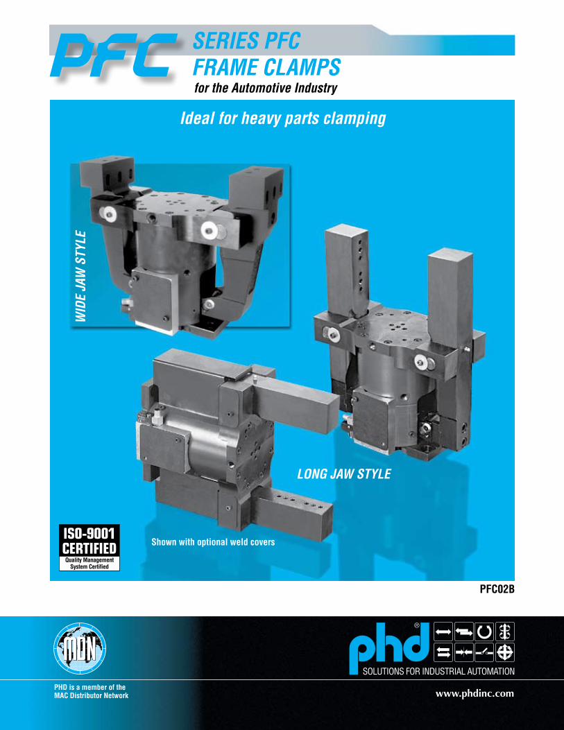
TO O
RD
ER S
PECI
FY:
Size
, Mou
ntin
g, J
aw S
tyle
Opt
ion,
Des
ign
No.
,Ja
w O
peni
ng (A
& B
), Fi
tting
Opt
ion,
Sen
sing
Opt
ion,
Wel
d Co
ver O
ptio
n if
desi
red.
PFC
4
UN
IT S
IZE
-1
JAW
STY
LE O
PTIO
NL
- Lon
g Ja
w S
tyle
W-W
ide
Jaw
Sty
le L16
T
4 - M
ediu
m D
uty
NO
TES:
1)M
etric
uni
ts h
ave
met
ric p
orts
and
mou
ntin
g.2)
-A s
witc
h on
ly a
vaila
ble
as A
1 (e
xam
ple
PS3A
1)
-LA
A
PORT
FIT
TIN
GS
-
DES
IGN
NO
.1
- Im
peria
l5
- Met
ricBL
ANK
- No
Fitti
ngLA
A - 9
0� S
wiv
el E
lbow
,M
etal
MO
UN
TIN
GT
- Rea
r Mou
ntin
g Pl
ate
REA
R
16-
PS3D
9-
WC1
-
16 -
16�
Ope
ning
JAW
OPE
NIN
G -
JAW
BW
ELD
CO
VER
OPT
ION
WC1
- W
eld
Cove
r(B
oth
Jaw
s)
-P S
3 D
9CO
NN
ECTO
R P
OSI
TIO
N1
- Par
alle
l to
jaw
s9
- Per
pend
icul
ar to
jaw
s
SWIT
CH H
OU
SIN
G P
OSI
TIO
N1
- Pos
ition
1 (P
ort S
ide)
3 - P
ositi
on 3
HO
USI
NG
OPT
ION
P - P
ositi
onal
Sen
sing
JAW
BJA
W A
CLO
SE P
ORT
OPE
N P
ORT
B001
-
BUSH
ING
BLO
CK O
PTIO
NB0
01 -
Cust
omer
mou
ntin
gpa
ttern
with
M10
thre
ads
and
10 m
mdo
wel
pin
hol
es
SEN
SIN
G O
PTIO
NS
- Sta
ndar
dR
- R
ever
sed
3(800) 624-8511
www.phdinc.com/pfcPFC0�B
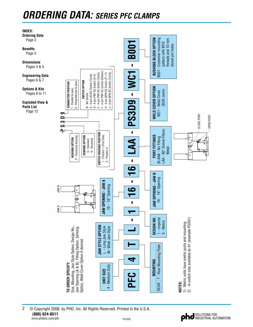
APPLICATION EXAMPLEThis application depicts clamping two channels of a truck
frame and welding along the seams. Wide spacing between the jaws allows for clamping larger parts than the competition allows.
The Series PFC Frame Clamps provide a large power window and clamp force of 11�50 lb [50040 N] at 3.94 in [100 mm] above tooling surface.
NAAMS™ standard mounting patterns on “L” style jaws and tooling surface provide fast setup with easy tooling and fixturing.
PFC4TL-1-16-16 SHOWN
TRUCK FRAMEFINGER TOOLINGSHIM PACK
SHIM PACKTOOLING REST
PFC4TL
PFC4TW
U.S. Patent No. 7,066,458 B2
SERIES PFC FRAME CLAMPS
Benefits• Rugged cam design provides consistent clamping force
throughout a wide power window.
• Constant high clamp force available throughout a wide powerwindow. The PFC4TL is 11�50 lb [50040 N] at 3.940 in[100 mm] above tooling surface. The PFC4TW is 7�00 lb[3�0�7 N] at �.187 in [55.6 mm] above tooling surface.
• Wide jaw throat accommodates large parts with simple tooling.
• Tooling surface has dowels and threads to North AmericanAutomotive Metric Standards (NAAMS™) NC blocks.
• “L” style jaws have dowels and threads for NAAMS™ mountingand shims.
• Modular design allows the jaws and bushing block to be easilyremoved for modification.
• Weld cover option protects internal mechanisms from flyingsparks and debris.
• Position sensing option provides open and closed sensingwith an industry standard AC or DC weldfield immune switchmounted in a protected housing.
• Operates quietly in less than .6 seconds. Flow controls are notrequired. Body has orifice communication which saves moneyand provides easy setup.
• Fully field repairable in less than 30 minutes using only 4metric hex wrenches.
• Lowest cost of ownership due to option availability to standardclamp without further modifications.
Industry Uses
• Automotive• General Industrial Automation
4(800) 624-8511
www.phdinc.com/pfc PFC0�B
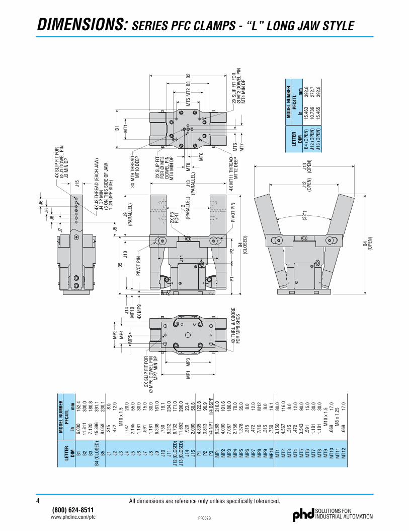
DIMENSIONS: SERIES PFC CLAMPS - “L” LONG JAW STYLE
All dimensions are reference only unless specifically toleranced.
B4(O
PEN
)
J12
(OPE
N)
J13
(OPE
N)
(32�
)
in6.
000
11.8
117.
120
15.3
969.
058
.315
.472
.787
2.16
51.
181
.591
1.18
16.
338
.750
9.21
26.
732
11.6
52.9
202.
000
4.83
53.
813
1/4
NPT
8.26
84.
000
7.08
72.
756
1.37
8.3
15.4
727/
16.3
15.7
503.
150
4.56
7.3
15.4
723.
543
.591
1.18
11.
181
.669
.669
LETT
ERD
IM B1 B2 B3B4
(CLO
SED
)B5 J1 J2 J3 J4 J5 J6 J7 J8 J9 J1
0J1
1J1
2 (C
LOSE
D)J1
3 (C
LOSE
D)J1
4J1
5P1 P2 P3 MP1
MP2
MP3
MP4
MP5
MP6
MP7
MP8
MP9
MP1
0M
T1M
T2M
T3M
T4M
T5M
T6M
T7M
T8M
T9M
T10
MT1
1M
T12
MO
DEL
NU
MBE
R
M10
x 1
.5
PFC4
TLm
m15
2.4
300.
018
0.8
391.
123
0.1
8.0
12.0
20.0
55.0
30.0
15.0
30.0
161.
019
.123
4.0
171.
029
6.0
23.4
50.8
122.
896
.91/
4 BS
PP21
0.0
101.
618
0.0
70.0
35.0
8.0
12.0
M12 8.0
19.1
80.0
116.
08.
012
.090
.015
.030
.030
.0
17.0
17.0
M10
x 1
.5
M8
x 1.
25
in15
.463
10.7
3615
.465
LETT
ERD
IMB4
(OPE
N)
J12
(OPE
N)
J13
(OPE
N)
MO
DEL
NU
MBE
RPF
C4TL
mm
392.
827
2.7
392.
8
P1P2
2X P
3PO
RT
MT5
MT1
MT2
MT8
MT7
4X M
T11
THR
EAD
MT1
2 D
EEP
2X S
LIP
FIT
FOR
� M
T3D
OW
EL P
INM
T4 M
IN D
P
3X M
T9 T
HR
EAD
MT1
0 D
EEP
J6
J6
J7
J6
B1M
P4
MP5
MP3
J12
(PAR
ALLE
L)
4X T
HR
U &
CBO
RE
FOR
MP8
SH
CS
2X S
LIP
FIT
FOR
� M
P6 D
OW
EL P
INM
P7 M
IN D
P
B5J9
(PAR
ALLE
L)
MT6
MT6
4X M
P9
J5
J10
B3
J15
MP1
MP2
J14
MP1
0
J11
PIVO
T PI
N
PIVO
T PI
N
B2
B4(C
LOSE
D)
4X S
LIP
FIT
FOR
� J
1 D
OW
EL P
INJ2
MIN
DP
4X J
3 TH
REA
D (E
ACH
JAW
)J4
DP
MIN
(3 O
N T
HIS
SID
E O
F JA
W1
ON
OPP
SID
E)
J13
(PAR
ALLE
L)
2X S
LIP
FIT
FOR
� M
T3 D
OWEL
PIN
MT4
MIN
DP
5(800) 624-8511
www.phdinc.com/pfcPFC0�B
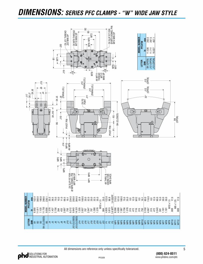
DIMENSIONS: SERIES PFC CLAMPS - “W” WIDE JAW STYLE
2X S
LIP
FIT
FOR
� M
P6 D
OW
EL P
INM
P7 M
IN D
P
4X T
HR
U &
CBO
RE
FOR
MP8
SH
CS
2X J
21 T
HR
EAD
J22
MIN
DP
3X M
T9 T
HR
EAD
MT1
0 M
IN D
P
2X S
LIP
FIT
FOR
� M
T3 D
OW
EL P
INM
T4 M
IN D
P
4X M
T11
THR
EAD
MT1
2M
IN D
P
2X P
3PO
RT
PIVO
T PI
N
PIVO
T PI
N
3X J
5 J9 (PAR
ALLE
L)
J12
(PAR
ALLE
L)J13
(PAR
ALLE
L)J1
1
P1P2
B4 (C
LOSE
D)
MP1
MP3
MP2
MP4
MP5
B1 MT1
MT5
MT2
B3B2
MT7
MT6
J15
J19
J20
3X J
7 3X J
8
J4J6
J18 J1
8
4X M
P9M
P10
J14
B5
J10
MT8
MT6
3X J
16
J17
in6.
000
11.8
117.
120
11.7
559.
058
1.37
81.
437
2.75
6.3
94.4
332.
697
.750
9.21
29.
843
14.3
311.
335
3.93
7.7
872.
047
.787
1.28
01.
378
.984
4.83
53.
813
1/4
NPT
8.26
84.
000
7.08
72.
756
1.37
8.3
15.4
727/
16.3
15.7
503.
150
4.56
7.3
15.4
723.
543
.591
1.18
11.
181
.669
.669
LETT
ERD
IM B1 B2 B3B4
(CLO
SED
)B5 J4 J5 J6 J7 J8 J9 J1
0J1
1J1
2 (C
LOSE
D)J1
3 (C
LOSE
D)J1
4J1
5J1
6J1
7J1
8J1
9J2
0J2
1J2
2P1 P2 P3 MP1
MP2
MP3
MP4
MP5
MP6
MP7
MP8
MP9
MP1
0M
T1M
T2M
T3M
T4M
T5M
T6M
T7M
T8M
T9M
T10
MT1
1M
T12
MO
DEL
NU
MBE
RPF
C4TW
mm
152.
430
0.0
180.
829
8.6
230.
135
.036
.570
.010
.011
.068
.519
.123
4.0
250.
036
4.0
33.9
100.
020
.052
.020
.032
.535
.0
25.0
122.
896
.91/
4 BS
PP21
0.0
101.
618
0.0
70.0
35.0
8.0
12.0
M12 8.0
19.1
80.0
116.
08.
012
.090
.015
.030
.030
.0
17.0
17.0
M10
x 1
.5
M8
x 1.
25
M10
x 1
.5
J12
(OPE
N)
J13
(OPE
N)
B4(O
PEN
)
32�
in11
.536
11.7
1116
.027
LETT
ERD
IMB4
(OPE
N)
J12
(OPE
N)
J13
(OPE
N)
MO
DEL
NU
MBE
RPF
C4TW
mm
293.
029
7.5
407.
1
All dimensions are reference only unless specifically toleranced.
6(800) 624-8511
www.phdinc.com/pfc PFC0�B
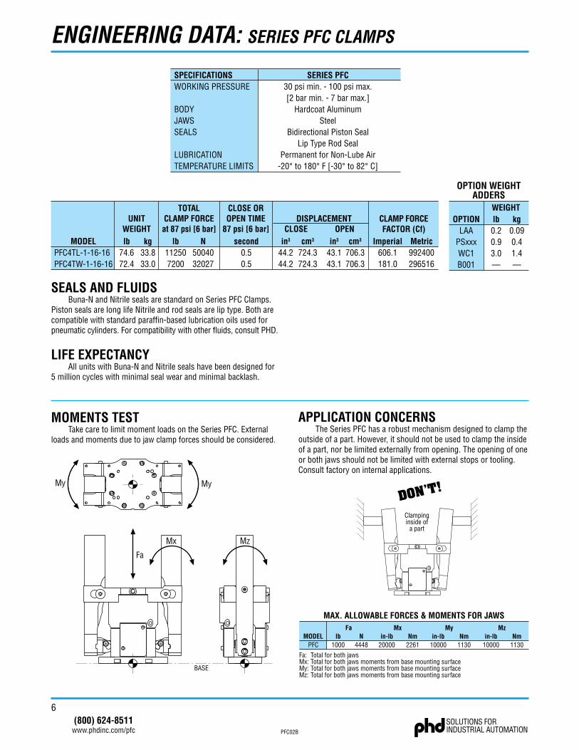
ENGINEERING DATA: SERIES PFC CLAMPS
SEALS AND FLUIDSBuna-N and Nitrile seals are standard on Series PFC Clamps.
Piston seals are long life Nitrile and rod seals are lip type. Both are compatible with standard paraffin-based lubrication oils used for pneumatic cylinders. For compatibility with other fluids, consult PHD.
LIFE EXPECTANCYAll units with Buna-N and Nitrile seals have been designed for
5 million cycles with minimal seal wear and minimal backlash.
UNITWEIGHT
TOTALCLAMP FORCEat 87 psi [6 bar]
CLOSE OROPEN TIME
87 psi [6 bar]lb
74.672.4
MODELPFC4TL-1-16-16PFC4TW-1-16-16
kg33.833.0
lb112507200
N5004032027
second0.50.5
lb0.20.93.0—
kg0.090.41.4—
OPTIONLAA
PSxxxWC1B001
OPTION WEIGHTADDERS
WEIGHT
in3
44.244.2
cm3
724.3724.3
DISPLACEMENTCLOSE OPEN
in3
43.143.1
cm3
706.3706.3
CLAMP FORCEFACTOR (Cf)
Imperial606.1181.0
Metric992400296516
SPECIFICATIONS SERIES PFCWORKING PRESSURE 30 psi min. - 100 psi max.
[2 bar min. - 7 bar max.]BODY Hardcoat AluminumJAWS SteelSEALS Bidirectional Piston Seal
Lip Type Rod SealLUBRICATION Permanent for Non-Lube AirTEMPERATURE LIMITS -20� to 180� F [-30� to 82� C]
MOMENTS TESTTake care to limit moment loads on the Series PFC. External
loads and moments due to jaw clamp forces should be considered.
Fa
Mx Mz
MyMy
BASE
DON’T!
Clampinginside of
a part
MODELPFC
Falb N
1000 4448
Mxin-lb Nm
20000 2261
Myin-lb Nm
10000 1130
Mzin-lb Nm
10000 1130
Fa: Total for both jawsMx: Total for both jaws moments from base mounting surfaceMy: Total for both jaws moments from base mounting surfaceMz: Total for both jaws moments from base mounting surface
MAX. ALLOWABLE FORCES & MOMENTS FOR JAWS
APPLICATION CONCERNSThe Series PFC has a robust mechanism designed to clamp the
outside of a part. However, it should not be used to clamp the inside of a part, nor be limited externally from opening. The opening of one or both jaws should not be limited with external stops or tooling. Consult factory on internal applications.
7(800) 624-8511
www.phdinc.com/pfcPFC0�B
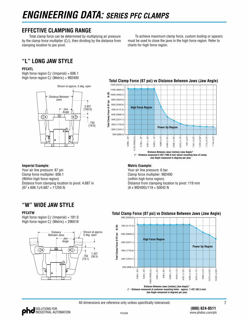
EFFECTIVE CLAMPING RANGE
3.937[100.0]
Distance BetweenJaws
JawAngle
.750[19.0]
Shown at approx. 5 deg. open
Total Clamp Force (87 psi) vs Distance Between Jaws (Jaw Angle)12000 [53378.7]
11000 [48930.4]
10000 [44482.2]
9000 [40034.0]
8000 [35585.8]
7000 [31137.5]
6000 [26689.3]
5000 [22241.1]
4000 [17792.9]
3000 [13344.7]
2000 [8896.4]
Distance Between Jaws (inches) (Jaw Angle)*(* - Distance measured 3.937 [100.0 mm] above mounting face of clamp
Jaw Angle measured in degrees per jaw)
6.69
8 (-
.25�
)
6.73
2 (P
ARAL
LEL)
6.76
6 (+
.25�
)
6.80
1 (+
.50�
)
6.83
5 (+
.75�
)
6.86
9 (+
1.0�
)
6.90
4 (+
1.25�)
6.93
8 (+
1.50�)
6.97
2 (+
1.75�)
7.00
7 (+
2.0�
)
7.04
1 (+
2.25�)
7.07
6 (+
2.50�)
7.11
0 (+
2.75�)
7.14
4 (+
3.0�
)
Tota
l Cla
mp
Forc
e @
87
psi
lb
[N]
High Force Region
Power Up Region
Total clamp force can be determined by multiplying air pressure by the clamp force multiplier (Cƒ), then dividing by the distance from clamping location to jaw pivot.
ENGINEERING DATA: SERIES PFC CLAMPS
Shown at approx.5 deg. open
JawAngle
DistanceBetween Jaws
.750(19.1)
1.437(36.5)
Total Clamp Force (87 psi) vs Distance Between Jaws (Jaw Angle)8000 [35585.8]
7000 [31137.5]
6000 [26689.3]
5000 [22241.1]
4000 [17792.9]
3000 [13344.7]
2000 [8896.4]
Distance Between Jaws (inches) (Jaw Angle)*(* - Distance measured at customer mounting holes - approx. 1.437 [36.5 mm]
Jaw Angle measured in degrees per jaw)
9.80
4 (-
.50�
)
9.82
3 (-
.25�
)
9.84
2 (P
ARAL
LEL)
9.86
1 (+
.25�
)
9.88
(+.5
0�)
9.89
9 (+
.75�
)
9.91
8 (+
1.0�
)
9.93
7 (+
1.25�)
9.95
6 (+
1.50�)
9.97
5 (+
1.75�)
9.99
4 (+
2.0�
)
10.0
13 (+
2.25�)
10.0
32 (+
2.50�)
Tota
l Cla
mp
Forc
e @
87
psi
lb
[N]
Power Up Region
High Force Region
“L” LONG JAW STYLE
Imperial Example:Your air line pressure: 87 psiClamp force multiplier: 606.1(Within high force region)Distance from clamping location to pivot: 4.687 in(87 x 606.1)/4.687 = 11�50 lb
PFC4TLHigh force region Cƒ (Imperial) = 606.1High force region Cƒ (Metric) = 99�400
To achieve maximum clamp force, custom tooling or spacers must be used to close the jaws in the high force region. Refer to charts for high force region.
Metric Example:Your air line pressure: 6 barClamp force multiplier: 99�400(within high force region)Distance from clamping location to pivot: 119 mm(6 x 99�400)/119 = 5004� N
“W” WIDE JAW STYLEPFC4TWHigh force region Cƒ (Imperial) = 181.0High force region Cƒ (Metric) = �96516
All dimensions are reference only unless specifically toleranced.
8(800) 624-8511
www.phdinc.com/pfc PFC0�B
OPTIONS & KITS: SERIES PFC CLAMPS
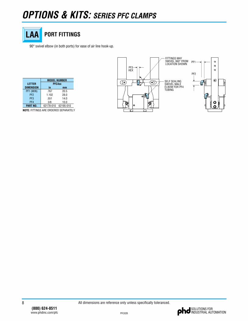
LAA PORT FITTINGS
NOTE: FITTINGS ARE ORDERED SEPARATELY
LETTERDIMENSIONPF1 (MIN)
PF2PF3PF4
PART NO.
in.7671.102.5513/8
62178-010
mm20.528.014.010.0
62195-010
PFC4xxMODEL NUMBER SELF SEALING
SWIVEL MALEELBOW FOR PF4TUBING
FITTINGS MAYSWIVEL 360� FROMLOCATION SHOWN
PF1
PF2
PF3HEX
90° swivel elbow (in both ports) for ease of air line hook-up.
All dimensions are reference only unless specifically toleranced.
9(800) 624-8511
www.phdinc.com/pfcPFC0�B
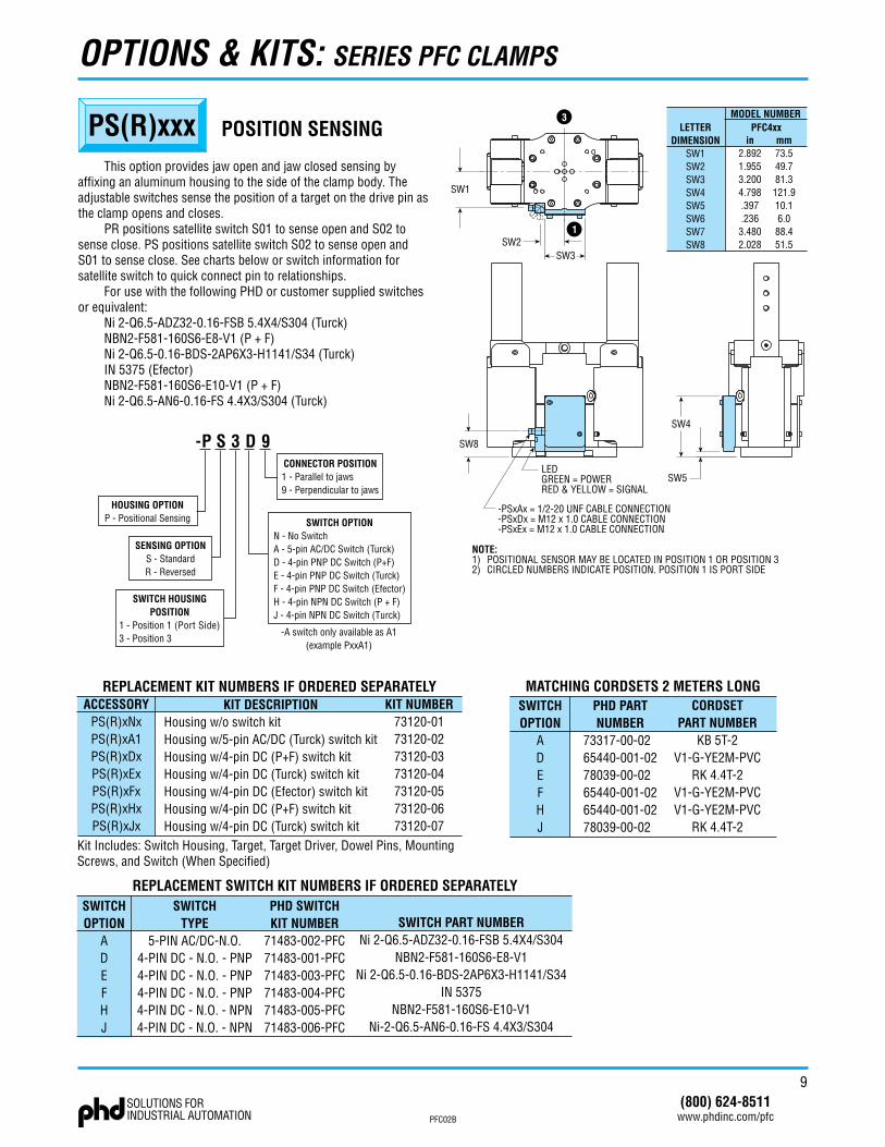
LETTERDIMENSION
SW1SW2SW3SW4SW5SW6SW7SW8
in2.8921.9553.2004.798.397.2363.4802.028
mm73.549.781.3121.910.16.088.451.5
PFC4xxMODEL NUMBER
NOTE:1) POSITIONAL SENSOR MAY BE LOCATED IN POSITION 1 OR POSITION 32) CIRCLED NUMBERS INDICATE POSITION. POSITION 1 IS PORT SIDE
SW5
SW4
Kit Includes: Switch Housing, Target, Target Driver, Dowel Pins, MountingScrews, and Switch (When Specified)
1
3
LEDGREEN = POWERRED & YELLOW = SIGNAL
-PSxAx = 1/2-20 UNF CABLE CONNECTION-PSxDx = M12 x 1.0 CABLE CONNECTION-PSxEx = M12 x 1.0 CABLE CONNECTION
SW2
SW1
SW8
SW3
REPLACEMENT KIT NUMBERS IF ORDERED SEPARATELYACCESSORY
PS(R)xNxPS(R)xA1PS(R)xDxPS(R)xExPS(R)xFxPS(R)xHxPS(R)xJx
KIT NUMBER73120-0173120-0273120-0373120-0473120-0573120-0673120-07
SWITCHOPTION
ADEFHJ
SWITCHTYPE
5-PIN AC/DC-N.O.4-PIN DC - N.O. - PNP4-PIN DC - N.O. - PNP4-PIN DC - N.O. - PNP4-PIN DC - N.O. - NPN4-PIN DC - N.O. - NPN
PHD SWITCHKIT NUMBER
71483-002-PFC71483-001-PFC71483-003-PFC71483-004-PFC71483-005-PFC71483-006-PFC
SWITCH PART NUMBERNi 2-Q6.5-ADZ32-0.16-FSB 5.4X4/S304
NBN2-F581-160S6-E8-V1Ni 2-Q6.5-0.16-BDS-2AP6X3-H1141/S34
IN 5375NBN2-F581-160S6-E10-V1
Ni-2-Q6.5-AN6-0.16-FS 4.4X3/S304
REPLACEMENT SWITCH KIT NUMBERS IF ORDERED SEPARATELY
SWITCHOPTION
ADEFHJ
PHD PARTNUMBER
73317-00-0265440-001-0278039-00-0265440-001-0265440-001-0278039-00-02
CORDSETPART NUMBER
KB 5T-2V1-G-YE2M-PVC
RK 4.4T-2V1-G-YE2M-PVCV1-G-YE2M-PVC
RK 4.4T-2
MATCHING CORDSETS 2 METERS LONGKIT DESCRIPTION
Housing w/o switch kitHousing w/5-pin AC/DC (Turck) switch kitHousing w/4-pin DC (P+F) switch kitHousing w/4-pin DC (Turck) switch kitHousing w/4-pin DC (Efector) switch kitHousing w/4-pin DC (P+F) switch kitHousing w/4-pin DC (Turck) switch kit
-P S 3 D 9CONNECTOR POSITION1 - Parallel to jaws9 - Perpendicular to jaws
SWITCH OPTIONN - No SwitchA - 5-pin AC/DC Switch (Turck)D - 4-pin PNP DC Switch (P+F)E - 4-pin PNP DC Switch (Turck)F - 4-pin PNP DC Switch (Efector)H - 4-pin NPN DC Switch (P + F)J - 4-pin NPN DC Switch (Turck)
SWITCH HOUSINGPOSITION
1 - Position 1 (Port Side)3 - Position 3
HOUSING OPTIONP - Positional Sensing
SENSING OPTIONS - StandardR - Reversed
-A switch only available as A1(example PxxA1)
PS(R)xxx POSITION SENSING
This option provides jaw open and jaw closed sensing by affixing an aluminum housing to the side of the clamp body. The adjustable switches sense the position of a target on the drive pin as the clamp opens and closes.
PR positions satellite switch S01 to sense open and S0� to sense close. PS positions satellite switch S0� to sense open and S01 to sense close. See charts below or switch information for satellite switch to quick connect pin to relationships.
For use with the following PHD or customer supplied switches or equivalent:
Ni �-Q6.5-ADZ3�-0.16-FSB 5.4X4/S304 (Turck)NBN�-F581-160S6-E8-V1 (P + F)Ni �-Q6.5-0.16-BDS-�AP6X3-H1141/S34 (Turck)IN 5375 (Efector)NBN�-F581-160S6-E10-V1 (P + F)Ni �-Q6.5-AN6-0.16-FS 4.4X3/S304 (Turck)
OPTIONS & KITS: SERIES PFC CLAMPS
10(800) 624-8511
www.phdinc.com/pfc PFC0�B
OPTIONS & KITS: SERIES PFC CLAMPS
All dimensions are reference only unless specifically toleranced.
1
2 3
4 LOAD
BN
BK
BU
WH
SENSOR S01
SENSOR S02
NPN DUAL NORMALLY OPEN4-WIRE DC (V1 TYPE)
LOAD
1
2 3
4 LOAD 1
BN
BK
BU
LOAD 2WH
SENSOR S1
SENSOR S2
1
2 3
4 LOAD 1
BN
BK
BU
LOAD 2WH
SENSOR S1
SENSOR S2
12
34
LOAD 1RD/WH RD/BK
LOAD 2RD
L1
L1
5
RD/YE
L2
L2
GN
SENSOR S01
SENSOR S02
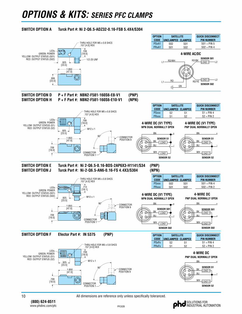
SWITCH OPTION A Turck Part #: Ni 2-Q6.5-ADZ32-0.16-FSB 5.4X4/S304
4-WIRE AC/DC
PNP DUAL NORMALLY OPEN4-WIRE DC (V1 TYPE)
PNP DUAL NORMALLY OPEN4-WIRE DC
SENSOR S01
SENSOR S02
1
2 3
4 LOAD 1
BN
BK
BU
LOAD 2WH
PNP DUAL NORMALLY OPEN4-WIRE DC
OPTIONCODEPSxA1PRxA1
SATELLITE QUICK DISCONNECTPIN NUMBERS01 = PIN 5S02 = PIN 4
UNCLAMPEDS02S01
CLAMPEDS01S02
OPTIONCODEPSxxxPRxxx
SATELLITE QUICK DISCONNECTPIN NUMBER
S1 = PIN 4S2 = PIN 2
UNCLAMPEDS2S1
CLAMPEDS1S2
OPTIONCODEPSxxxPRxxx
SATELLITE QUICK DISCONNECTPIN NUMBERS01 = PIN 4S02 = PIN 2
UNCLAMPEDS02S01
CLAMPEDS01S02
OPTIONCODEPSxFxPRxFx
SATELLITE QUICK DISCONNECTPIN NUMBER
S1 = PIN 4S2 = PIN 2
UNCLAMPEDS2S1
CLAMPEDS1S2
1/2-20 UNF
THRU HOLE FOR M5 x 0.8 SHCS.157 [4.0] HEX
.709[18.0]
1.850[47.0]
.906[23.0]
.925[23.5]
SO1
SO2
CONNECTORPOSITION 9
CONNECTORPOSITION 1
90
M12 x 1
LEDsGREEN: POWER
YELLOW: OUTPUT STATUS (S1)RED: OUTPUT STATUS (S2)
THRU HOLE FOR M5 x 0.8 SHCS.157 [4.0] HEX
.925[23.5]
1.850[47.0]
.709[18.0]
.709[18.0]
SWITCH OPTION D P + F Part #: NBN2-F581-160S6-E8-V1 (PNP)SWITCH OPTION H P + F Part #: NBN2-F581-160S6-E10-V1 (NPN)
SWITCH OPTION E Turck Part #: Ni 2-Q6.5-0.16-BDS-2AP6X3-H1141/S34 (PNP)SWITCH OPTION J Turck Part #: Ni-2-Q6.5-AN6-0.16-FS 4.4X3/S304 (NPN)
CONNECTORPOSITION 9
CONNECTORPOSITION 1
90
.925[23.5]
THRU HOLE FOR M5 x 0.8 SHCS.157 [4.0] HEX
M12 x 1
1.850[47.0]
.709[18.0]
.713[18.1]
SWITCH OPTION F Efector Part #: IN 5375 (PNP)
CONNECTORPOSITION 9
CONNECTORPOSITION 1
90
M12 x 1
THRU HOLE FOR M5 x 0.8 SHCS.157 [4.0] HEX
.925[23.5]
1.850[47.0]
.709[18.0]
.709[18.0]
1
2 3
4 LOAD
BN
BK
BU
WH
SENSOR S1
SENSOR S2
NPN DUAL NORMALLY OPEN4-WIRE DC (V1 TYPE)
LOAD
LEDsGREEN: POWER
YELLOW: OUTPUT STATUS (S01)RED: OUTPUT STATUS (S02)
LEDsGREEN: POWER
YELLOW: OUTPUT STATUS (S1)RED: OUTPUT STATUS (S2)
LEDsGREEN: POWER
YELLOW: OUTPUT STATUS (S01)RED: OUTPUT STATUS (S02)
11(800) 624-8511
www.phdinc.com/pfcPFC0�B
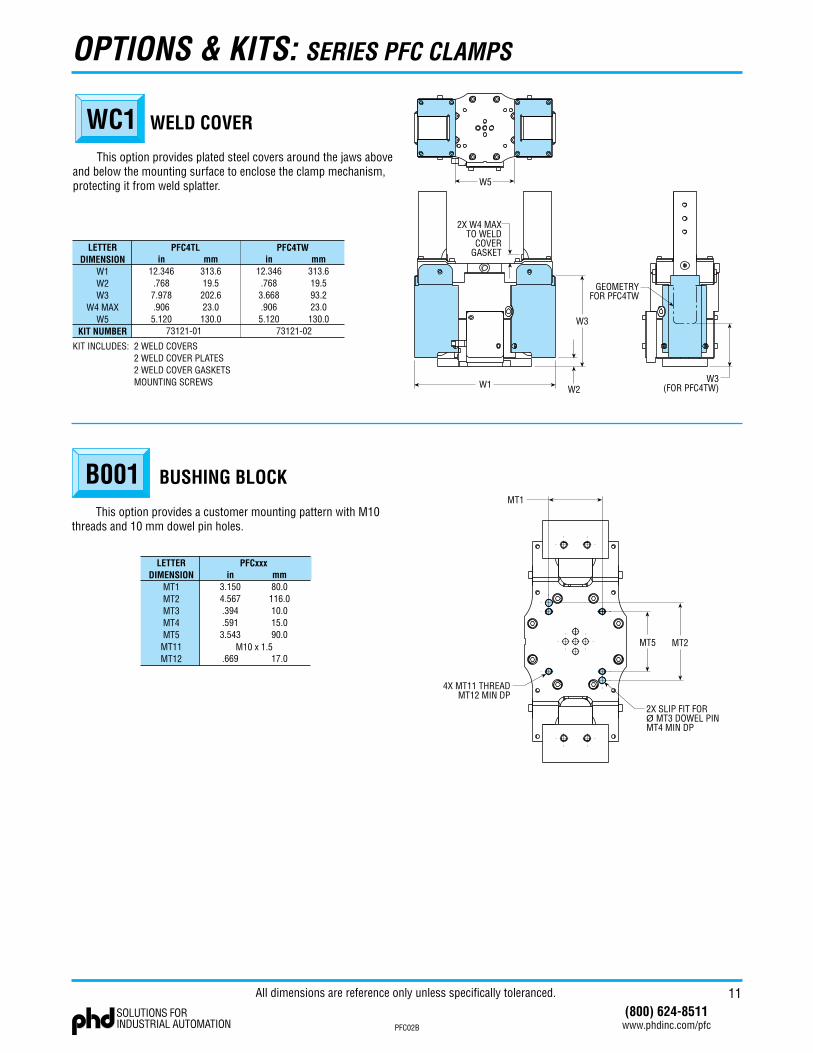
WC1 WELD COVER
KIT INCLUDES: 2 WELD COVERS2 WELD COVER PLATES2 WELD COVER GASKETSMOUNTING SCREWS
LETTERDIMENSION
W1W2W3
W4 MAXW5
KIT NUMBER
in12.346.7687.978.9065.120
mm313.619.5202.623.0130.0
PFC4TL
W1 W2
W373121-01
in12.346.7683.668.9065.120
mm313.619.593.223.0130.0
PFC4TW
73121-02
W3(FOR PFC4TW)
GEOMETRYFOR PFC4TW
2X W4 MAXTO WELD
COVERGASKET
W5
This option provides plated steel covers around the jaws above and below the mounting surface to enclose the clamp mechanism, protecting it from weld splatter.
OPTIONS & KITS: SERIES PFC CLAMPS
B001 BUSHING BLOCK
This option provides a customer mounting pattern with M10 threads and 10 mm dowel pin holes.
LETTERDIMENSION
MT1MT2MT3MT4MT5MT11MT12
in3.1504.567.394.5913.543
.669
mm80.0116.010.015.090.0
17.0
PFCxxx
M10 x 1.5
MT1
MT5 MT2
4X MT11 THREADMT12 MIN DP
All dimensions are reference only unless specifically toleranced.
1�
PFC0�B
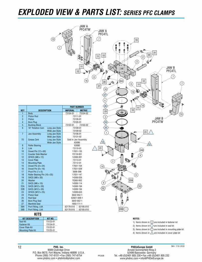
EXPLODED VIEW & PARTS LIST: SERIES PFC CLAMPS
NOTES:
1) Items shown in are included in fastener kit
2) Items shown in are included in seal kit
3) Items shown in are included in mounting plate kit
4) Items shown in are included in cover plate kit
JAW APFC4TL
1
2
3
4
5
7
7
8
8
9
9
1211
20
21
2120
36A
26
27
24
25
23
1811
12
1211
10
6
22A
22B
15
36B
21
1313
21
JAW BPFC4TL
17
16
14
12
11
7D
7
7D
JAW BPFC4TW
7
19
18
16
JAW APFC4TW
KIT DESCRIPTIONSeal KitFastener KitCover Plate KitMounting Plate Kit
KIT NO.73123-0173124-0173122-0173125-01
KITS
PART NUMBER
KEY123456
7
7D
89
101112131415161718192021
22A22B2324252627
36A36B
DESCRIPTIONBodyPiston RodPistonBore PlugBushing Block16� Rotation Cam Long Jaw Style
Wide Jaw StyleJaw Assembly Long Jaw Style
Wide Jaw StyleGrease Zerk Long Jaw Style
Wide Jaw StyleRoller BearingLinkDowel Pin (12 x 60)Counter Sink WasherSFHCS (M6 x 12)Cover PlateMounting PlateDowel Pin (8 x 24)Dowel Pin (8 x 16)Pivot Pin (1 x 5)Roller Bearing Pin (16 x 55)SHCS (M8 x 30)WasherSHCS (M6 x 10)SHCS (M12 x 30)SHCS (M12 x 30)SFHCS (M12 x 25)Piston SealRod SealBore Plug SealManifold SealPort Fitting, LAAPort Fitting, LAA
IMPERIAL73104-01
73102-01
62178-01062178-010
METRIC73104-02
73102-02
62195-01062195-010
73111-0173126-0173105-01
73109-0173109-0273106-0173131-02
Sold in Jaw Assembly6308663080
73110-0117831-13573119-00114308-00173113-0173112-01
17831-10417831-0393696-098
17831-14714308-02670365-00214308-11414308-19414308-19414308-6333642-052-1
62827-009-13642-052-11950-111-1
3M-I 7/10 8133PHD, Inc.9009 Clubridge Drive
P.O. Box 9070, Fort Wayne, Indiana 46899 U.S.A.Phone (260) 747-6151 • Fax (260) 747-6754
www.phdinc.com • [email protected]
PHDinEurope GmbHArnold-Sommerfeld-Ring 252499 Baesweiler, Germany
Tel. +49 (0)2401 805 230 • Fax +49 (0)2401 805 232www.phdinc.com • [email protected]