Embed Size (px)
Citation preview

For the adsorption transfer of thin cloths, films, printed circuit boards, etc.
Stainless steel
High lifting force
28.3 N5.7 times that of the existing model(Existing model: 5.0 N a ZNC60: 28.3 N)
Energy saving
Max. 72 % reduction∗1
∗1 Comparison of air consumption to lifting force
ZNC40 Body material: Resin
30 g
With vibration suppression coverVibration noise:
Max. 17 dB[A] reductionSuppresses the vibration noise of thin workpieces
With stopperPrevents workpiece slippage
3 types of body materials
Aluminium
Resin
NBR
Silicone rubber
Stainless steel type
Resin type
CAT.EUS100-145A-UK
ZNC Series
Bernoulli GripperØ 40, Ø 60
NewNew

Bernoulli Gripper ZNC Series
When a fl at, hard, non-breathable workpiece such as glass is
adsorbed, it will be gripped without direct contact.
As the gripper approaches the workpiece, the fl ow speed of the air fl owing between the gripper
and the workpiece increases, creating a vacuum and adsorbing the workpiece. In the case of a
fl at, hard, non-breathable workpiece such as glass, it will be in a non-contact state. The lifting
force of the gripper and the weight of the workpiece is balanced around 0.2 to 0.5 mm.
The rubber stopper prevents the workpiece from sliding.
By attaching stoppers, the state changes from non-contact to contact and the workpiece is gripped.
For fl at and hard workpieces such as glass, it is recommended to have stoppers to prevent slipping.
When using a soft workpiece such as cloth or paper, it may come into contact with the gripper and
generate vibration noise. In this case, it is recommended to have a vibration suppression cover.
∗ Only the rubbers of the stopper can be replaced.
∗ The stopper reduces the lifting force.
Application Examples
For the adsorption of thin cloths For the adsorption of paperFor the adsorption of printed circuit boards For the adsorption of bubble wrap
Basic type (Without vibration suppression cover/stopper)
With stopper
With vibration suppression cover
Stopper
Vibration suppression cover
Suppresses the vibration that occurs when a soft workpiece such as cloth or paper is adsorbed
The vibration suppression cover suppresses the vibration generated when a soft workpiece, such as cloth
or paper, comes into contact with the gripper, and reduce the generation of sound. Air fl ows at high speed
in the gap between the vibration suppression cover and the workpiece, enabling stable suction transfer.
∗ With the vibration suppression cover, the status is changed to contact instead of non-contact.
∗ The vibration suppression cover reduces the lifting force.
1
0.2 to 0.5 mm
WorkpieceNegative pressureNegative pressure
Workpiece
Negative pressure
Negative pressureNegative pressure

Bernoulli Gripper ZNC Series
Requires no piping
Multiple ports Air supply port
Direct porting is possible.
∗ The O-ring should be
provided by the customer.
�Release portWorkpieces can be removed
easily.
� A pressure sensor
option can be selected.
Detects the presence of a workpiece
∗ Connects to the multi-port
Piping from the top and side is possible.
Clean air is discarded from the inside to the
outside. There is no clogging of foreign matter.
Can be used as a sensor port or release port
Body material: Aluminium
Anti-corrosive type
Body material: Stainless steel
Material Size Weight [g]
AttachmentPressure
sensorWith stopperWith vibration suppression cover
Resin Stainless steel
Aluminium40 48
NBR
(Improved abrasion resistance)
Silicone rubber
(Heat/ozone resistant)
� �
With
or
without
60 110 — �
Resin40 30 � —
60 67 — �
Stainless
steel
40 139 — �
60 323 — �
Bernoulli gripper construction
Piping port
Series Variations
Construction and working principle
Release air OUT
Release air IN
Lightweight type
Body material: Resin
2
Vacuum generation
Compressed
air
Supply port
Defl ector
BodyMulti-port
Workpiece
O-ring

Selection Procedure
ZNC Series
Model Selection
[Basic type]
[With stopper/vibration suppression cover]
Selection example
Selection example
W = M x g x t x 1n
W : Required lifting force [N]
M : Workpiece mass [kg]
g : Gravitational acceleration [= 9.8 m/s2]
t : Safety factor (Recommended value: 2 or more)
n : Number of Bernoulli grippers [pcs.]
W = M x g x t x 1n
W : Required lifting force [N]
M : Workpiece mass [kg]
g : Gravitational acceleration [= 9.8 m/s2]
t : Safety factor (Recommended value: 2 or more)
n : Number of Bernoulli grippers [pcs.]
Workpiece mass: M = 0.7 kg
Safety factor: t = 2
Number of Bernoulli grippers: n = 2 pcs.
Required lifting force: W = 0.7 x 9.8 x 2 x 12
= 6.9 N
Basic type
Workpiece: Smooth and non-permeable
Operating pressure: 0.3 MPa
Per lifting force graph for supply pressure
Lifting force of the ZNC40 > Required lifting force
Workpiece mass: M = 0.25 kg
Safety factor: t = 2
Number of Bernoulli grippers: n = 1 pc.
Required lifting force: W = 0.25 x 9.8 x 2 x 11
= 4.9 N
With stopper
Workpiece: Smooth and non-permeable
Operating pressure: 0.4 MPa
Per lifting force graph for the distance to the workpiece
With stopper: Lifting force is checked at 1 mm.
(With vibration suppression cover: Lifting force is checked at 1.5 mm.)
Lifting force of the ZNC40 > Required lifting force
The lifting force changes depending on the shape, size, surface unevenness,
breathability, fl exibility, etc., of the workpiece. Use the selection result as a reference
value and perform verifi cation and confi rmation on the actual machine.
The lifting force changes depending on the shape, size, surface unevenness,
breathability, fl exibility, etc., of the workpiece. Use the selection result as a reference
value and perform verifi cation and confi rmation on the actual machine.
Step 1 Calculate the lifting force.
Step 1 Calculate the lifting force.
Step 2 Model selection
Step 2 Model selection
Lifting Force (ZNC40)
Lifting Force–Distance from the Workpiece (ZNC40)
0 0.60.50.40.30.20.1
16
14
12
10
8
6
4
2
0
0 32.521.510.5
14
12
10
8
6
4
2
0
0.1 [MPa]
0.4 [MPa]
0.3 [MPa]
0.2 [MPa]
0.5 [MPa]
3
Supply pressure [MPa]
Lifting forc
e [
N]
Distance from the workpiece [mm]
Lifting forc
e [N
]

Bernoulli Gripper
ZNC Series
q Body size
40 Ø 40 mm
60 Ø 60 mm
w Body material
— Aluminium
P Resin
SStainless
steel
r Pressure sensor
— None
SWith pressure sensor
Part no.: PSE541-M5-X2
∗ The pressure sensor is shipped together with the product but does not come assembled.
e Attachment
— Basic type (Without attachment)
PN
With stopper
NBR (Black)
PSSilicone rubber
(White)
VP With vibration
suppression
cover∗1
Resin
VS Stainless steel
∗1 Refer to the Table 1 . With Vibration Sup-pression Cover for the size and material.
∗ Stopper cannot be added afterward.
∗ Vibration suppression cover can be added to the basic type afterward.
∗ The stopper and vibration suppression cover cannot be used together.
Table 1. With Vibration Suppression Cover
Symbol MaterialBody size
symbol
Body material
Aluminium Resin Stainless steel
VP Resin40 � � —
60 — — —
VS Stainless steel40 � — �
60 � � �
How to Order
ZNC 40
q w e r
Stopper
Vibration suppression cover
∗ With 3 stoppers and 3 spring pinsFor replacement instructions e Refer
to page 10.
∗ With 3 mounting screws for stainless steel
ZNCM PS 2
Material
PN NBR (Black)
PS Silicone rubber (White)
Material
VP Resin
VS Stainless steel
ZNCM 40 VP
Body size
40 Ø 40 mm
60 Ø 60 mm
Attachments/Part Nos.
NBR
Resin
Silicone rubber
Stainless steel
4

Specifi cations
ZNC40�
ZNC60�
Model ZNC40 ZNC60
Lifting force [N]∗1 13.8 28.3
Air consumption [l/min] (ANR)∗2 182 182
Type Bernoulli
Fluid Air
Operating pressure 0.1 to 0.5 MPa
Proof pressure 0.75 MPa
Ambient and
operating
temperatures∗3
Body
material
Aluminium −5 to 80 °C (0 to 50 °C)
Resin −5 to 40 °C (0 to 40 °C)
Stainless steel −5 to 80 °C (0 to 50 °C)
Grease Grease-free
Weight [g]∗4 Body
material
Aluminium 48 110
Resin 30 67
Stainless steel 139 323
Pressure sensor∗5 PSE541-M5-X2 (Grease-free)
Rated pressure range: 0 to −101 kPa
∗1 Lifting force of the basic type for max. supply pressure. Values when a fl at and non-breathable workpiece is adsorbed
∗2 Air consumption for max. supply pressure
∗3 No freezing or condensation. The values in ( ) are for models with a pressure sensor.
∗4 Weight for the basic type without a plug
∗5 For pressure sensor details, refer to the PSE 5 4 0 series in the Web Catalogue and the Operation Manual.
Lifting Force
Lifting Force
Consumption Flow Rate
Consumption Flow Rate
Lifting Force–Distance from the Workpiece
Lifting Force–Distance from the Workpiece
0 0.60.50.40.30.20.1
16
14
12
10
8
6
4
2
0
0 0.60.50.40.30.20.1
30
25
20
15
10
5
0
0 0.60.50.40.30.20.1
200
180
160
140
120
100
80
60
40
20
0
0 0.60.50.40.30.20.1
200
180
160
140
120
100
80
60
40
20
0
0 32.521.510.5
14
12
10
8
6
4
2
0
0.1 [MPa]
0.4 [MPa]
0.3 [MPa]
0.2 [MPa]
0.5 [MPa]
0 32.521.510.5
30
25
20
15
10
5
0
0.1 [MPa]
0.4 [MPa]
0.3 [MPa]
0.2 [MPa]
0.5 [MPa]
5
ZNC Series
Supply pressure [MPa] Supply pressure [MPa] Distance from the workpiece [mm]
Supply pressure [MPa] Supply pressure [MPa] Distance from the workpiece [mm]
Lifting forc
e [
N]
Consum
ption fl o
w r
ate
[l/m
in (
AN
R)]
Lifting forc
e [
N]
Lifting forc
e [N
]
Consum
ption fl o
w r
ate
[l/m
in (
AN
R)]
Liftin
g forc
e [N
]

qutyr
w !0eu
!0!1
oi
Construction
Component PartsNo. Description Material (Surface treatment) Note
1 Body
Aluminium alloy (Anodised) Body material For aluminium
Synthetic resin Body material For resin
Stainless steel Body material For stainless steel
2 Defl ector
Aluminium alloy (Anodised) Body material For aluminium
Synthetic resin Body material For resin
Stainless steel Body material For stainless steel
3 Helical insert Stainless steel Body material For resin
4 O-ring FKM
5 Hexagon socket head cap screw Stainless steel
6 Flat washer Stainless steel
7 Plug Stainless steel/FKM
8 StopperNBR
With stopper
Refer to page 4 for
part numbers.
Silicone rubber∗1, ∗2
9 Spring pin Stainless steel
10 Vibration suppression coverSynthetic resin
With vibration
suppression coverStainless steel
11 Hexagon socket head cap screw Stainless steel
∗1 Compliant with the FDA’s (U.S. Food and Drug Administration) 21CFR§177.2600 dissolution test
∗2 Compliant with the standards for “Rubber apparatus (excluding baby drinking apparatus) and containers/packaging” (D3) (Partial revision: Japanese Ministry of Health, Labour, and Welfare Notifi cation No. 595, 2012) in
Section 3 “Apparatus and Containers/Packaging” of the Food Sanitation Act, Article 1 8 “Specifications and
Standards for Food and Food Additives, etc.” (Japanese Ministry of Health and Welfare Notifi cation No. 3 7 0 ,
1959)
6
Bernoulli Gripper ZNC Series
Basic typeWith vibration suppression cover: Resin
With stopper
With vibration suppression cover: Stainless steel

120°
120°
120° 1
20°
6.545° 45°
A
B
C
10.5
16.5
12D
17.5
17.5
2.2
F
G
1
Ø 5
.8
E
∗1 Supply air to either air supply port PA or PB. Seal the unused ports
with plugs.
∗2 Seal the multi-port with a plug when not in use.
∗3 The stopper and cover cannot be used together.
∗4 The product is shipped with plugs in the air supply port PA and multi-
port.
After determining which port to use, it is recommended to apply
adhesive to the threads of the two air supply ports and the multi-port.
∗5 The O-ring is not included. Attach an O-ring (13.5 x 11.5 x 1) if
necessary.
∗ Ø 40 only
∗6 Use the multi-port as a sensor mounting or release port.
∗ For pressure sensor details, refer to the PSE540 series in the Web
Catalogue and the Operation Manual.
∗ The pressure sensor is shipped together with the product but does not
come assembled.
Dimensions
With stopper
Basic type
With vibration suppression cover
Cover material: Resin
Cover material: Stainless steel
Dimensions [mm]
ModelA B C D E F G Weight [g]∗1
Outer body dia. Body material
ZNC
40
—
40 32 11 3.5 34 42.2 44
48
P 30
S 139
60
—
60 47 21 10 54 — 64
110
P 67
S 323
∗1 The stopper, vibration suppression cover, and plug weights are not included.
7
ZNC Series
Stopper ∗3
Ø 1.2 Multi-port connecting hole
4 x M4 x 0.7 thread depth 8M5 x 0.8 thread depth 4
Multi-port ∗2, ∗4, ∗6
M5 x 0.8 thread depth 4
Air supply port PA ∗1, ∗4
M5 x 0.8 thread depth 4
Air supply port PB ∗1
Air supply port PA ∗5
Counterbore diameter Ø 13.5,
depth 0.8
With a plug attached: 2
With a plug attached: 2
3 x M2.5 thread depth 5
∗ When Ø 40 body material is resin, there is no threaded part.
Vibration
suppression cover ∗3

Mounting
1. Be careful not to drop or hit the product to avoid
scratches and dents.
Even slight deformation of the suction surface can decrease
product performance.
2. When installing the product, tighten it with an
appropriate tightening torque.
If excessive or insufficient tightening torque is applied, sealing
failure or loose screws may result. Adhesive is recommended
for screws.
Body Mounting
ModelBody
materialScrew size
Thread
length [mm]
Tightening
torque [N·m]
ZNC40 Aluminium
M4 x 0.7 8
1.5
ZNC40P Resin 0.76
ZNC40S Stainless steel 1.5
ZNC60 Aluminium 1.5
ZNC60P Resin 0.76
ZNC60S Stainless steel 1.5
3. When installing the stainless steel vibration suppression
cover, tighten it with the proper tightening torque.
If excessive or insufficient tightening torque is applied, loose
screws may result. Adhesive is recommended for screws.
Vibration Suppression Cover Mounting (Stainless steel type only)
ModelBody
materialScrew size
Thread
length [mm]
Tightening
torque [N·m]
ZNC40 Aluminium
M2.5 x 0.45 5
0.36
ZNC40P Resin 0.18
ZNC40S Stainless steel 0.36
ZNC60 Aluminium 0.36
ZNC60P Resin 0.18
ZNC60S Stainless steel 0.36
4 . When installing tube fitting (supply port), pressure
sensor (multi-port), and plugs, tighten them with an
appropriate tightening torque. Retighten all bolts
regularly.
If excessive or insufficient tightening torque is applied, loose
screws may result. Loose bolts may cause air leakage or
falling of parts. Retighten them regularly and apply adhesive.
Supply Port
ModelBody
materialScrew size
Thread
length [mm]
Tightening
torque [N·m]
ZNC40 Aluminium
M5 x 0.8 4
1 to 1.5
ZNC40P Resin 0.5 to 1
ZNC40S Stainless steel 1 to 1.5
ZNC60 Aluminium 1 to 1.5
ZNC60P Resin 0.5 to 1
ZNC60S Stainless steel 1 to 1.5
Design / Selection
1. In the Bernoulli gripper, air flows between the suction
surface and the workpiece when the workpiece is
adsorbed. The workpiece is then gripped without
direct contact, making it easy to slide sideways.
Consider an external guide, etc., for safety design.
The workpiece may fall due to the influence of external force or inertial force
during workpiece transportation. This can cause injury or damage the equipment.
2. The product performance of the Bernoulli gripper
varies greatly depending on the type of workpiece.
Please make your selection carefully.
The lifting force changes depending on the shape, size, surface
unevenness, breathability, flexibility, etc., of the workpiece.
3. Select the Bernoulli gripper with sufficient margin
for acceleration/deceleration, vibration, shock, and
wind pressure during workpiece transportation.
Ensure a safety factor for the allowable lifting force. The recommended
value is 2 or more. If necessary, reduce external force and install a
wind pressure prevention cover to design a safe application.
4. When adjusting the distance between the Bernoulli gripper and
the workpiece, design your application taking the performance
characteristics for the distance into consideration.
The lifting force changes depending on the distance from the workpiece.
5. When adsorbing food, take sufficient safety meas-
ures. Additionally, please contact us in advance.
6. The product performance described in the catalogue is based on
the condition that the workpiece is larger than the product suction
surface, and the workpiece is smooth and non-breathable.
If the workpiece is smaller than the product suction surface,
the lifting force may be reduced or it may not be possible to lift.
Please check with customer’s equipment before use.
Specifi c Product Precautions 1Be sure to read this before handling the products.
ZNC Series
8
No restraining force in the horizontal direction
ImpactWind pressure
prevention cover
Acceleration
Restrain horizontal movement with a guide.
Win
d
pre
ssure
Workpiece size
Workpiece size
Bernoulli gripper size
Bernoulli gripper size

Mounting
5. When mounting the product directly without piping,
smooth the mounting surface and use an appropri-
ate O-ring. (The O-ring should be provided by the
customer.)
Installation on a mounting surface with a rough surface,
scratches or dents, or mounting an unsuitable O-ring may
cause sealing failure.
Recommended O-ring
Model Size
ZNC40�13.5 x 11.5 x 1
ZNC60�
Air Supply
1. Use compressed air and control the cleanliness.
Install an air filter, air dryer, or a mist separator. A system with
a quality grade of No. C or higher in the air preparation
equipment model selection guide of Best Pneumatics No. 6 is
recommended.
Handling
1. Depending on the use conditions, the workpiece
may come into contact with the main body at the
moment of suction even if it is a basic body type. If
the product with stopper or with vibration suppres-
sion cover is used, it will come into contact with the
workpiece.
2. The NBR stopper is not suitable for an ozone
environment, so select silicone rubber.
Deterioration is accelerated in ozone environments such as in
clean rooms, around ionizers or motor equipment.
3. The stopper and vibration suppression cover cannot
be used together.
4. If a thin and soft workpiece is adsorbed, a high
frequency sound may be produced. This generation
of sound is due to the vibration of the workpiece,
and is not a product abnormality.
Sound generation may be reduced by reducing the supply
pressure or using the vibration suppression cover type.
5. Depending on the type of workpiece and usage
conditions, the pressure sensor may not be able to
detect the workpiece or the sensor value may differ.
The vacuum pressure changes depending on the type of
workpiece and the conditions of use. Please verify the product
with the actual machine before actual operation.
Handling
6. When arranging the Bernoulli grippers, consider the
position of the centre of gravity of the workpiece to
maintain balance.
If the mounting position of the product and the position of the
centre of gravity of the workpiece are misaligned, the rotational
force acts due to the weight of the workpiece, which may
cause it to come off.
7. When installing the vibration suppression cover
(synthetic resin), align the centre position of the
product name plate and the SMC logo of the vibra-
tion suppressor.
If the mounting position is not correct, the vibration suppres-
sion cover may interfere with the fittings, etc., resulting in dete-
rioration of product performance and damage to the cover.
8. Stopper cannot be added afterward.
Since the body shape of the basic type and the stopper type
are different, it is not possible to add a stopper to the basic
type. If you order the stopper type and then remove the
stopper to use it as the basic type, the lifting force will be lower
than the basic type.
The vibration suppression cover can be added to the basic
type afterward.
Specifi c Product Precautions 2Be sure to read this before handling the products.
ZNC Series
9
O-ring
Moment generation
Name plate
Stopper
Basic type With stopper
Stopper insertion
hole
Maintenance
1. Do not disassemble or modify the body of the product.
If the disassembled and/or modified, the functions and performance
may not be achieved and the product will not be warrantied.
2 . In periodical inspections, check the following items
and replace the parts if necessary.
a) Scratches, gouges, abrasion, corrosion
b) Air leakage (Retighten the fitting and plugs.)
c) Twisting, crushing, and turning of connected tubes
d) Hardening, deterioration, and softening of connected tubes
e) Cracks, wear, and deformation of the stopper
3. Replacement of the stopper
If the stopper is not mounted correctly, the product perfor-
mance may deteriorate and the stopper may be damaged.
1
2
3
4
Specifi c Product Precautions 3Be sure to read this before handling the products.
ZNC Series
10
Insert the spring pin to a new stopper.
Insert the spring pin to the end.
Use a precision screwdriver to push the
spring pin out of the side hole in the
body and remove the spring pin and
stopper.
Insert the new stopper with a spring pin
to the body.∗1
∗ 1 Apply alcohol for easier insertion.
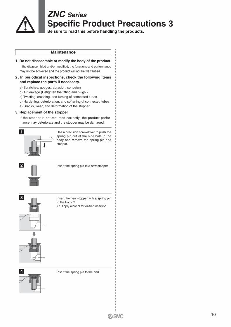
These safety instructions are intended to prevent hazardous situations and/or equipment damage. These instructions indicate the level of potential hazard with the labels of “Caution,” “Warning” or “Danger.” They are all important notes for safety and must be followed in addition to International Standards (ISO/IEC) 1), and other safety regulations.
1) ISO 4414: Pneumatic fl uid power – General rules relating to systems.ISO 4413: Hydraulic fl uid power – General rules relating to systems.IEC 60204-1: Safety of machinery – Electrical equipment of machines.
(Part 1: General requirements)ISO 10218-1: Manipulating industrial robots - Safety.etc.
Safety Instructions
Caution:Caution indicates a hazard with a low level of risk which, if not avoided, could result in minor or moderate injury.
Warning:Warning indicates a hazard with a medium level of risk which, if not avoided, could result in death or serious injury.
Danger:Danger indicates a hazard with a high level of risk which, if not avoided, will result in death or serious injury.
Caution1. The product is provided for use in manufacturing industries.
The product herein described is basically provided for peaceful use in manufacturing industries. If considering using the product in other industries, consult SMC beforehand and exchange specifi cations or a contract if necessary.If anything is unclear, contact your nearest sales branch.
CautionSMC products are not intended for use as instruments
for legal metrology.
Measurement instruments that SMC manufactures or sells have not been qualifi ed by type approval tests relevant to the metrology (measurement) laws of each country.Therefore, SMC products cannot be used for business or certifi cation ordained by the metrology (measurement) laws of each country.
Limited warranty and
Disclaimer/ Compliance
RequirementsThe product used is subject to the following “Limited warranty and Disclaimer” and “Compliance Requirements”. Read and accept them before using the product.
Limited warranty and Disclaimer1. The warranty period of the product is 1 year in service or 1.5
years after the product is delivered, whichever is fi rst. 2) Also, the product may have specifi ed durability, running distance or replacement parts. Please consult your nearest sales branch.
2. For any failure or damage reported within the warranty period which is clearly our responsibility, a replacement product or necessary parts will be provided. This limited warranty applies only to our product independently, and not to any other damage incurred due to the failure of the product.
3. Prior to using SMC products, please read and understand the warranty terms and disclaimers noted in the specifi ed catalogue for the particular products.
2) Vacuum pads are excluded from this 1 year warranty.A vacuum pad is a consumable part, so it is warranted for a year after it is delivered. Also, even within the warranty period, the wear of a product due to the use of the vacuum pad or failure due to the deterioration of rubber material are not covered by the limited warranty.
Compliance Requirements1. The use of SMC products with production equipment for the
manufacture of weapons of mass destruction (WMD) or any other weapon is strictly prohibited.
2. The exports of SMC products or technology from one country to another are governed by the relevant security laws and regulations of the countries involved in the transaction. Prior to the shipment of a SMC product to another country, assure that all local rules governing that export are known and followed.
Safety Instructions Be sure to read “Handling Precautions for SMC Products” (M-E03-3) before using.
Warning1. The compatibility of the product is the responsibility of the person
who designs the equipment or decides its specifi cations.
Since the product specifi ed here is used under various operating conditions, its compatibility with specifi c equipment must be decided by the person who designs the equipment or decides its specifi cations based on necessary analysis and test results. The expected performance and safety assurance of the equipment will be the responsibility of the person who has determined its compatibility with the product. This person should also continuously review all specifi cations of the product referring to its latest catalogue information, with a view to giving due consideration to any possibility of equipment failure when confi guring the equipment.
2. Only personnel with appropriate training should operate machinery
and equipment.
The product specifi ed here may become unsafe if handled incorrectly. The assembly, operation and maintenance of machines or equipment including our products must be performed by an operator who is appropriately trained and experienced.
3. Do not service or attempt to remove product and machinery/
equipment until safety is confi rmed.
1. The inspection and maintenance of machinery/equipment should only be performed after measures to prevent falling or runaway of the driven objects have been confi rmed.
2. When the product is to be removed, confi rm that the safety measures as mentioned above are implemented and the power from any appropriate source is cut, and read and understand the specifi c product precautions of all relevant products carefully.
3. Before machinery/equipment is restarted, take measures to prevent unexpected operation and malfunction.
4. Contact SMC beforehand and take special consideration of safety
measures if the product is to be used in any of the following
conditions.
1. Conditions and environments outside of the given specifi cations, or use outdoors or in a place exposed to direct sunlight.
2. Installation on equipment in conjunction with atomic energy, railways, air navigation, space, shipping, vehicles, military, medical treatment, combustion and recreation, or equipment in contact with food and beverages, emergency stop circuits, clutch and brake circuits in press applications, safety equipment or other applications unsuitable for the standard specifi cations described in the product catalogue.
3. An application which could have negative effects on people, property, or animals requiring special safety analysis.
4. Use in an interlock circuit, which requires the provision of double interlock for possible failure by using a mechanical protective function, and periodical checks to confi rm proper operation.

Specifi cations are subject to change without prior notice and any obligation on the part of the manufacturerPrinting ZT 00 Printed in Spain
SMC Corporation (Europe)Austria +43 (0)2262622800 www.smc.at offi [email protected] +32 (0)33551464 www.smc.be [email protected] +359 (0)2807670 www.smc.bg offi [email protected] Croatia +385 (0)13707288 www.smc.hr offi [email protected] Republic +420 541424611 www.smc.cz offi [email protected] Denmark +45 70252900 www.smcdk.com [email protected] Estonia +372 6510370 www.smcpneumatics.ee smc@[email protected] +358 207513513 www.smc.fi smcfi @smc.fi France +33 (0)164761000 www.smc-france.fr [email protected] +49 (0)61034020 www.smc.de [email protected] +30 210 2717265 www.smchellas.gr [email protected] +36 23513000 www.smc.hu offi [email protected] +353 (0)14039000 www.smcautomation.ie [email protected] +39 03990691 www.smcitalia.it [email protected] +371 67817700 www.smc.lv [email protected]
Lithuania +370 5 2308118 www.smclt.lt [email protected] +31 (0)205318888 www.smc.nl [email protected] +47 67129020 www.smc-norge.no [email protected] +48 222119600 www.smc.pl offi [email protected] +351 214724500 www.smc.eu [email protected] +40 213205111 www.smcromania.ro [email protected] +7 (812)3036600 www.smc.eu [email protected] +421 (0)413213212 www.smc.sk offi [email protected] +386 (0)73885412 www.smc.si offi [email protected] +34 945184100 www.smc.eu [email protected] +46 (0)86031240 www.smc.nu [email protected] +41 (0)523963131 www.smc.ch [email protected] +90 212 489 0 440 www.smcpnomatik.com.tr [email protected] UK +44 (0)845 121 5122 www.smc.uk [email protected]
South Africa +27 10 900 1233 www.smcza.co.za [email protected]


![TH series TH-1.6 series Through hole tap · Jig for removing adsorption film [TH-JIG] (1unit/pack) This jig is used for removing the adsorption films after mounting. Film can be removed](https://img.pdfslide.us/doc/110x75/5c96008009d3f2396f8ba011/th-series-th-16-series-through-hole-tap-jig-for-removing-adsorption-film-th-jig.jpg)