Embed Size (px)
Citation preview
1
DETAILED SPECIFICATIONS
FOR THE
CONSTRUCTION OF A
48'-0” LOA TWIN SCREW TOWBOAT
For
Tennessee Department of
Transportation Houston-Benton
County Ferry
March, 2021
2
DOCUMENT NOTE
The vessel described by these specifications is a near sister vessel to the vessel PATIENCE
constructed for TDOT in 2014. This document is an adaptation of the Specifications that were
written for the PATIENCE, following the same format for commonality and cross-reference.
The original specifications were authored by Farrell and Norton Naval Architects, Inc. for
bidding of the original detail design and construction. This document incorporates elements of
the detail design subsequently carried out for PATIENCE as well as features unique to the new
vessel, and is prepared by Seacraft Design, LLC.
TABLE OF CONTENTS
SECTION I GENERAL
SECTION II HULL CONSTRUCTION
SECTION III DECK HOUSE AND PILOTHOUSE
SECTION IV PROPULSION AND STEERING
SECTION V AUXILIARIES
SECTION VI ELECTRICAL
SECTION VII PIPING
SECTION VIII HVAC
SECTION IX NAVIGATION AND ELECTRONICS
SECTION X ALARMS
SECTION XI REQUIREMENTS FOR LIVING AND MESSING
SECTION XII LIFE SAVING AND SAFETY EQUIPMENT
SECTION XIII FENDER SYSTEM AND DECK EQUIPMENT
SECTION XIV PAINTING
SECTION XV DISCREPANCIES
3
SECTION I - GENERAL
101. INTENT:
It is the intent of these specifications and plans that the Respondent shall deliver to the State, a
towboat complete in all respects, ready for operation, fully equipped, and fitted out in accordance
with the best commercial marine practice, complying with all the applicable requirements of the
several regulatory bodies of the United States listed herein, and ready for service intended. The
principal criteria of this towboat shall be providing:
1. Propulsion of passenger ferry
2. USCG Subchapter M certification
The vessel is to be a near sister vessel to the PATIENCE, ON 1244273, Serodino, Inc. hull 130,
which was developed from a concept design by Farrell and Norton Naval Architects, Inc., and from
the subsequent detail design by Seacraft Design, LLC for the Builder. These specifications and the
Contract Drawings are modified from the construction documents prepared for that vessel, and the
vessel itself shall serve as a reference for the expectations with respect to function, fit and finish.
On-Site Visit:
1. It is highly recommended that an on-site visit be made to the sister vessel PATIENCE.
The State of Tennessee is not responsible for errors or omissions in bid costs due to not
having made a site visit.
2. Respondents will be given a 4 week period to schedule the site visit with the solicitation
coordinator (reference the Schedule of Events document attached to this solicitation).
Appointment time, location and on-site contact information will be issued to the
Respondent upon scheduling their appointment successfully. To schedule email:
102. DEFINITIONS
Wherever the words defined to this paragraph, or pronouns used in their stead, occur in these
specifications, they have the following meanings: 1. Purchaser shall hereafter be referred to as the State.
2. The shipyard building the vessel shall hereafter be referred to as Respondent or Builder.
3. The words “approval of the State” or “approved by the State” Shall mean as approved in writing
by the State.
4. The words “supply and install” shall be taken to mean that the Respondent shall provide and
install the specified material and equipment, even though one of the words only is used.
5. Class or Classed shall mean a group of ships of a similar size.
6. Load line is the marking indicating the extent to which the weight of a load may safely submerge
a ship, by way of a waterline limit.
7. United States Coast Guard (USCG) shall mean the branch of the U.S. Armed Forces and agency
within the Department of Homeland Security charged with enforcing U.S. maritime laws and
ensuring the safety of the nation's ports and waterways.
8. ABS – American Bureau of Shipping
9. FRP – Fiberglass Reinforced Plastic
10. LOA - Length Over All
11. Load Lines means – Marking indicating the extent to which the weight of a load may safely
4
submerge a ship.
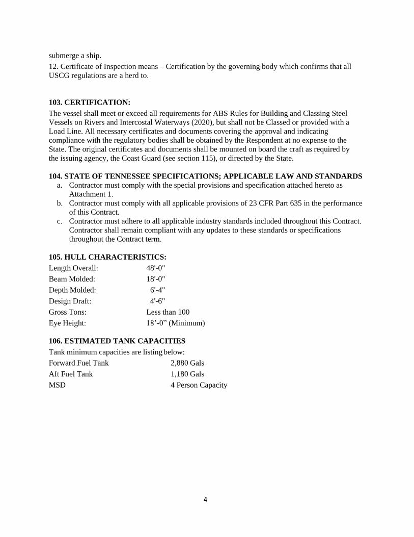
12. Certificate of Inspection means – Certification by the governing body which confirms that all
USCG regulations are a herd to.
103. CERTIFICATION:
The vessel shall meet or exceed all requirements for ABS Rules for Building and Classing Steel
Vessels on Rivers and Intercostal Waterways (2020), but shall not be Classed or provided with a
Load Line. All necessary certificates and documents covering the approval and indicating
compliance with the regulatory bodies shall be obtained by the Respondent at no expense to the
State. The original certificates and documents shall be mounted on board the craft as required by
the issuing agency, the Coast Guard (see section 115), or directed by the State.
104. STATE OF TENNESSEE SPECIFICATIONS; APPLICABLE LAW AND STANDARDS
a. Contractor must comply with the special provisions and specification attached hereto as
Attachment 1.
b. Contractor must comply with all applicable provisions of 23 CFR Part 635 in the performance
of this Contract.
c. Contractor must adhere to all applicable industry standards included throughout this Contract.
Contractor shall remain compliant with any updates to these standards or specifications
throughout the Contract term.
105. HULL CHARACTERISTICS:
Length Overall: 48'-0"
Beam Molded: 18'-0"
Depth Molded: 6'-4"
Design Draft: 4'-6"
Gross Tons: Less than 100
Eye Height: 18’-0” (Minimum)
106. ESTIMATED TANK CAPACITIES
Tank minimum capacities are listing below:
Forward Fuel Tank 2,880 Gals
Aft Fuel Tank 1,180 Gals
MSD 4 Person Capacity
5
106. INSPECTION:
All work and material entering into the construction of the vessel and its machinery, fittings and
equipment shall be subject at all times to the inspection by the STATE. Any work not satisfactory
either from defective material, departure from specifications, or poor workmanship, shall be removed
or replaced to the satisfaction of the inspector at the RESPONDENT’S expense. There shall be
thorough inspections by the STATE at 30% complete and 60% complete during construction to
inspect for workmanship and accuracy of working plans as specified by USCG standards.
There shall be a Builder’s certification inspection by the State at the Respondent’s shipyard prior to
leaving the yard. Certificate of Inspection (COI) must be issued by USCG district of destination for
the towboat.
107. MATERIALS:
All materials intended for use, and all equipment used, shall be as specified or as shown on plans,
except on written order from the USCG inspector, and should the Respondent desire to substitute
any material or equipment for that specified, Respondent must first obtain an order from TDOT in
writing. As Per TDOT Special Provision 106A-Buy America Requirements. Material Mill
Certifications must be obtained and provided to TDOT prior to usage by the boat’s Builder.
Steel plate, shapes and other metal work shall be of the best quality for its particular purpose. All
steel used in the project shall be American made. More specifications can be seen at Section 203 –
Hull Construction.
Paints, electrical equipment, wiring machinery, outfitting and all other equipment entering into the
construction or for installation shall conform to the standards of the first-class material for
commercial ships of this class and as specified herein. All wood used must be properly seasoned and
selected for the particular use to which it is to be put.
Plywood shall be marine type in all cases.
108. WORKMANSHIP:
Workmanship throughout shall be first class or high grade, and in all respects suitable for the
intended use. Particular care shall be taken to ensure fair lines, adequate and proper fastening,
suitable butts and scarfs, smooth surfaces, neat and substantial work and maximum degree of water
tightness. All welding shall be done by certified welders; which meets or exceeds USCG
regulations. Proof of certification must be supplied prior to manufacturing. The installation of
machinery, fittings and equipment shall be carried out in the latest approved marine fashion equal to
the best modern practice, and specified herein.
6
109. ALTERATION & CHANGES:
The State reserves the right to make any deletions or additions to the work to be performed, without
invalidating the Contract. These deletions or additions shall be mutually agreed upon by both the
State and the Respondent.
The RESPONDENT may substitute other sizes and types of material than that specified, providing
the same is of equal quality, strength and suitability for the use intended and that the State’s approval
is obtained in writing. Changes to the vessel after the award shall be at no charge to the State of
Tennessee. While the State is willing to allow changes, the bid price is firm and no additional cost
may be incurred to the State for these changes. All changes or modifications must receive prior
written approval by the State. Documentation must be provided to the State regarding the changes.
110. MATERIALS SUPPLIED BY STATE:
The Respondent shall receive, unload, store, place on the boat, and install without extra charge
all material, machinery and equipment hereafter specified as being supplied by STATE.
111. TRIALS AND TESTS:
On completion of the craft and prior to the underway trials, all structure, machinery, piping, electrical
systems, firefighting systems, and lifesaving equipment shall be thoroughly tested in accordance with
these specifications and requirements of the USCG to demonstrate proper working order and that all
requirements of the specifications have been fulfilled. Any defects which may develop or become
apparent in connection with the work covered herein shall be corrected by the RESPONDENT. The
result of these entire tests shall be recorded. When the craft is in all respects ready for delivery to the
STATE, the RESPONDENT shall conduct sea trials in accordance USCG regulations.
112. GUARANTEE:
The Respondent must replace or make repairs for all parts of the hull, outfit, machinery, etc. which
fail as a result of defective material or workmanship which may occur within one (1) year from date
of acceptance by STATE. With respect to the equipment purchased from others and incorporated in
the towboat, the Respondent shall be responsible only to the extent of the usual warranty or
guarantee of the manufacturer or supplier of such equipment. It is understood that this does not
cover ordinary wear and tear or accident beyond control of the Respondent and the Respondent shall
not be liable or contingent or consequential damages resulting from aforesaid failures.
7
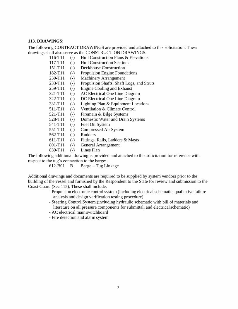
113. DRAWINGS:
The following CONTRACT DRAWINGS are provided and attached to this solicitation. These
drawings shall also serve as the CONSTRUCTION DRAWINGS. 116-T11 (-) Hull Construction Plans & Elevations
117-T11 (-) Hull Construction Sections
151-T11 (-) Deckhouse Construction
182-T11 (-) Propulsion Engine Foundations
230-T11 (-) Machinery Arrangement 233-T11 (-) Propulsion Shafts, Shaft Logs, and Struts
259-T11 (-) Engine Cooling and Exhaust
321-T11 (-) AC Electrical One Line Diagram
322-T11 (-) DC Electrical One Line Diagram
331-T11 (-) Lighting Plan & Equipment Locations
511-T11 (-) Ventilation & Climate Control
521-T11 (-) Firemain & Bilge Systems
528-T11 (-) Domestic Water and Drain Systems
541-T11 (-) Fuel Oil System
551-T11 (-) Compressed Air System 562-T11 (-) Rudders
611-T11 (-) Fittings, Rails, Ladders & Masts
801-T11 (-) General Arrangement 839-T11 (-) Lines Plan
The following additional drawing is provided and attached to this solicitation for reference with
respect to the tug’s connection to the barge: 612-B01 B Barge – Tug Linkage
Additional drawings and documents are required to be supplied by system vendors prior to the
building of the vessel and furnished by the Respondent to the State for review and submission to the
Coast Guard (Sec 115). These shall include:
- Propulsion electronic control system (including electrical schematic, qualitative failure
analysis and design verification testing procedure)
- Steering Control System (including hydraulic schematic with bill of materials and
literature on all pressure components for submittal, and electrical schematic) - AC electrical main switchboard
- Fire detection and alarm system
8
114. DELIVERY:
Respondent shall be required to deliver the ferry and towboat to the Tennessee Department of
Transportation at Cumberland City, TN – Cumberland River Mile 104. The ramp on one end of the
ferry may be removed and re-attached for delivery at Respondent’s expense. The Barge (Volunteer)
is already in Cumberland City, however the Respondent may find it necessary to have the barge
transported to their shipyard during construction to ensure proper application to the towboat. If so,
all expenses will be at the Respondent’s expense including Ferry and Towboat “if necessary”.
115. COAST GUARD INSPECTION, PLAN APPROVAL AND STABILITY
The vessel requires a Certificate of Inspection by the U.S. Coast Guard as a Towing Vessel subject to
the regulations of 46 CFR Parts 136 - 144, Subchapter M. The Application for Inspection (filed by
the Respondent) shall indicate that the State is electing the Coast Guard option for design
verification, and plans shall be submitted to the Coast Guard Marine Safety Center by the State’s
technical representative (Seacraft Design, LLC), who shall serve as Coast Guard liaison for the plan
review process.
Construction of the Vessel shall be under the inspection of the cognizant inspection office of the US
Coast Guard. Access to work shall be afforded to Coast Guard inspectors at all reasonable times, and
the Respondent shall notify the Coast Guard of salient inspection points as mutually agreed.
Stability Instructions shall be developed after construction but prior to sea trials by the State’s
technical representative (Seacraft Design, LLC), based on calculations derived from the results of
a Coast Guard witnessed Deadweight Survey, and submitted for approval by the Marine Safety
Center.
9
SECTION II- HULL CONSTRUCTION
201. GENERAL:
The hull shall be an all welded, steel constructed design as required for river towing service. It shall
consist of a rake bow, midsection, and a cantilevered stern. The hull shall be constructed on a
transverse framing system. The frame spacing shall be maximum of 24”.
The hull shall be single chine with a design assuring good entry and water flow to the propellers.
Stanchions and supports shall be provided where required to support concentrated loads,
deck machinery, etc. Swash plates shall be furnished in tanks where required.
Limber holes and vent holes to be cut in floors, keelson, longitudinals, etc., to provide drainage
for venting of all compartments.
202. WELDING:
Welding shall comply with American Bureau of Shipping (ABS) and USCG rules and to be
performed by welders who meet the qualifications of USCG.
Electrodes to be of shield arc type.
The amount of welding on the boat shall be so carried out as to reduce the buckling of plating both in
hull and in the deckhouse to a minimum. Unsightly buckles shall be removed. Reference Table 10,
Fairness of Plating Between Frames in the “ABS GUIDE FOR SHIPBUILDING AND REPAIR
QUALITY STANDARD FOR HULL STRUCTURES DURING CONSTRUCTION. 2007”.
203. HULL CONSTRUCTION:
The hull shall be of transversely framed steel construction, as shown by drawings 116-T11 and 117-
T11. Structural steel used for the construction of this vessel shall be ASTM A-36 or equal and
certified to be of domestic manufacture.
All hull tanks shall be tested as per ABS Steel Vessel Under 90 Meter Rules. These tests should be
performed in the presence of the State and the USCG if required by Subchapter M. Bottom frames
aft of the engine room shall be double continuously welded. Bulwarks shall be fabricated from
3/16” plate.
204. DECK FITTINGS:
Deck fittings of weldments shall be furnished and installed as shown on drawings. Deck shall
be reinforced with insert plates under all fittings.
205. MANHOLES:
Manholes into fuel tanks shall be 15” x 23" bolted type. Manholes on deck into lazarette and hull
voids shall be 18” round flush type of aluminum construction. There shall be a 24”x24” raised
watertight hatch into the forepeak storage area.
206. LIFTING BEAMS:
The main engines shall have lifting beams located in the engine room to help facilitate the removal or
maintenance of either of the main engines.
10
SECTION III-DECKHOUSE AND PILOTHOUSE
301. GENERAL:
The deckhouse shall be constructed of stiffened 1/4" steel plate, as shown on drawing 151-T11.
302. HAND RAILING:
Railings shall be provided in accordance with drawing 611-T11.
303. FLOORS AND GRATINGS:
Checkered aluminum floor plates, 1/4" thick, shall be provided in engine room to cover engine
room, except in way of main engines and auxiliary machinery. Floor plates shall be held in place by
3/8 stainless steel hex head screws. Checkered aluminum removable plates shall also be installed on
the raised aft deck over the steering gear.
Galley, Mess, Head & Pilothouse - FLEXCO RADIAL II rubber tile flooring or equal, trimmed with
4” rubber base mold around all perimeters.
304. JOINER:
All interior wall panels shall be constructed using .030” Textured Fiberglass Reinforced Plastic
(FRP) laminated to 3/8” plywood secured with chrome plate screws and beauty washers. Panels
shall be screwed to nailers arranged as required. Panels shall be installed as to provide quick-
removable access to wire ways and/or other machinery. All panels shall terminate 1/2” above the
deck.
305: BATHROOM FIXTURES:
BATHROOM FIXTURES: The following bathroom fixtures shall be provided as shown on the
drawings: Acceptable brands shall be American Standard, Kohler, Moen or Equal
a. TOILETS: One (1) Standard elongated bowl residential design porcelain bowl and tank units
furnished with first-quality hardware (subject to the State’s approval), with water supply line
equipped with shut-off valve, and seats.
b. LAVATORIES: One (1) corner mount Vanity, recessed bowl type with chrome plated faucets and
first-quality hardware (subject to the State’s approval), with water supply lines equipped with shut-
off valves.
c. MIRROR: One (1) wall mounted, mirror located above the lavatory.
d. VENT FANS: One (1) ceiling mounted vent fans exhausting to the outside. Vent
lines to have a damper in line.
e. SOAP TRAYS: Each lavatory shall be furnished with a first-quality chrome plated soap tray,
mounted above the bowl (subject to State’s approval).
f. TOILET PAPER HOLDER: Each toilet shall be furnished with a first quality, chrome plated toilet
paper holder (subject to the State’s approval). g. PAPER TOWEL DISPNSER
h. WASTE RECEPTACLE
306: GALLEY EQUIPMENT:
Galley to have installed one “dorm size approximately 20” x 19” x 33” refrigerator and microwave,
as well as a stainless steel single basin sink. Plumbing and electrical outlets for equipment shall be
installed by the Respondent. Counters and cabinets to be installed as shown on DRAWINGS.
11
307. DOORS AND WINDOWS:
Exterior doors in the main deckhouse and pilothouse, three (3) places total, shall be of aluminum
weathertight construction. Doors shall be Pacific Coast Marine PWE-3072 or equal.
Interior cabin doors shall be of 1-3/8" metal marine joiner doors.
Door between crew area and engine room shall be steel fire retarding joiner door, with spring loaded
hinges to keep door in closed position at all times.
Windows shall be fitted in deckhouse and pilothouse as indicated on the plans. Windows in the main
deckhouse shall be fixed type with aluminum frames. Windows in the pilothouse shall be sliding
opening with aluminum frames. All glass shall be 3/8” thickness tempered safety glass. All windows
to have a 3” radius or as required by window manufacturer.
One electric driven pendulum type outline mounted windshield wiper shall be installed on the fixed
center panel of the forward window. One electric driven fan for defrosting center pilothouse window
shall be installed.
All windows shall have installed a Mylar or equal reflective tinted shade system. Each window shall
have its own shade which shall be able to be locked in place at the bottom, similar to the arrangement
on PATIENCE.
308. HARDWARE:
All hardware including locks, hinges, hook stops, to be of bronze standard term pattern. Hinges
for watertight doors shall be of steel.
309. STAIRWAYS AND LADDERS:
Stairways and ladders shall be provided as follows:
One (1) in engine room fwd to crew space (stairway)
One (1) in engine room aft to aft deck (stairway)
One (1) aft deck to 01 deck aft (stairway) One (1) 01 deck to pilothouse deck (stairway)
One (1) main deck to pilot deck forward (vertical ladder) One (1) from 01 deck to pilothouse
roof (vertical ladder) Ladders in tanks shall be provided as necessary.
310: REMOVABLE SOFT HATCH:
A soft hatch shall be provided on the 01 Deck above both the port and the starboard engines, and
shall be designed to be unbolted and removed for future maintenance and/or engine and gear
removal. The design shall incorporate the use of weather seals and bolted connections for ease of
removal. All bolts, washers, and nuts shall be Stainless Steel.
311: DECK DRAINAGE:
All decks, above the main deck, shall have deck drains. These drains shall have grating on top and
a pipe running to the deck below.
12
SECTION IV-PROPULSION & STEERING
401. MAIN ENGINES:
The Respondent shall supply, install and properly align two main propulsion diesel engines, which
shall be John Deere model 6090AFM85, 286 BHP @ 2100 rpm M1 rating, EPA Tier 3 emissions
certified, arranged for keel cooling, dry exhaust and 12V electric start, control and instrumentation
or the CAT C7.1 Tier 3 emissions.
Each propulsion engine shall be close-coupled to a marine reverse/reduction gearbox, which shall be
Twin Disc model MG-5091DC, with 3.82:1 reduction ratio and mechanical control valve (no
electronic control available in this model). A gear oil cooler shall be provided for integration with
the engine keel cooling circuit (see section 705).
All engine filters and fills shall be placed on inboard side of engine as much as possible.
The engine/gear assemblies shall be mounted on structural foundations as detailed on drawing 182-
T11. The Respondent shall provide specialized labor, tools, parts and machine work to align and
install pour able chocks and machine-fit alignment bolts below each engine and gear mounting pads
as required. After the engines and the gears are aligned and the alignment has been approved, the
Respondent shall provide and install all engine soft connections (i.e. exhaust, fuel, jacket water,
after cooler water, combustion air intake, etc.).
Propulsion throttle and shift controls shall be electronically controlled by a Twin Disc EC300 system
with single station control. A system diagram of the control system along with QFA and DVTP
documents suitable for submission to the Coast Guard shall be furnished by the equipment vendor.
The vendor quoted engine, gearbox and control package with all options and accessories shall be
subject to State review and approval.
402. STACKS:
Stacks shall be constructed of 1/4" steel plate of dimension as shown on the drawings. Stacks
shall be fitted with exhaust louvers for ventilation of stacks and engine room.
403. ENGINE COOLING AND EXHUST SYSTEMS:
Engine cooling and exhaust systems shall be as described by drawing 259-T11. Engine coolers shall
be sized for minimum 0 knot in 90 degree water. Cooling system to shall have 5-10 gallon day tanks
for filling.
404. PROPELLER SHAFTS AND COUPLINGS:
Propeller shafts shall be 3 1/2" diameter Aquamet 17 or equal boat shafting. Machining, couplings
and bearings shall be as described by drawing 233-T11.
405. STERN TUBES & SHAFT STRUTS:
Stern tubes, support struts and shaft seals shall be as described by drawing 233-T11. There shall be
provided stern tubes fabricated from heavy wall seamless steel mechanical tubing. The shaft seals
shall be Simplan greaseless type. The struts shall be fabricated “V” type.
406. PROPELLERS:
The Respondent shall furnish and install two marine propellers, which shall be 44” diameter x 28”
pitch, 4 blade, Michigan Wheel “Workhorse” or approved equal, of nickel-aluminum-bronze (nibral),
with tips turning outboard at the top when moving ahead.
13
407. STEERING SYSTEM:
The Respondent shall furnish and install a complete electrical over hydraulic full follow-up steering
control system, similar to that on PATIENCE, supplied, sized and designed by Skipper Engineered
Products. This system shall incorporate a right hand and left hand steering and flanking sticks
mounted on the pilothouse console. The steering and flanking sticks shall connect to steering system
that control hydraulic valves located below. Two hydraulic pumps, one engine driven and one genset
powered shall be installed. Each pump shall be independently capable of operating all flanking and
steering rudder cylinders.
The hydraulic cylinders shall be connected to the pressure piping by means of 3000 PSIG hydraulic
hoses. The hoses shall have swivel connections and be a uniform length of hose to valves as much as
possible. The hydraulic system shall be capable of swinging the rudders from hard-over to hard-over
in 10 Seconds, with a maximum hard-over angle of 45 Degrees. Drawings and documentation
necessary for submission to the Coast Guard shall be provided by the vendor, including hydraulic
and electric schematics, and literature on all pressurized components.
408. STEERING RUDDERS:
The vessel shall be supplied with two (2) steering rudders as described by drawing 562-T11,
comprised of stiffened 3/8” steel plate on 3 1/2" diameter C1018 stocks with bearing sleaves.
Rudder bearings shall be housed in bored ends of each rudder tube, with upper rudder bearings of
bronze set over packing and arranged for greasing, and with lower bearings of the water lubricated
style.
409. FLANKING RUDDERS:
The vessel shall be supplied with four (4) flanking rudders as described by drawing 562-T11,
comprised of stiffened 3/8” steel plate on 3 1/2" diameter C1018 stocks. Rudder bearings shall be
housed in bored ends of each rudder tube, with upper rudder bearings of bronze set over packing
and arranged for greasing, and with lower bearings of the water lubricated style.
410. STEERING TILLERS & JOCKEY BARS:
Each rudder shall be provided with a steering tiller assembly, custom fabricated in general
accordance with drawing 562-T11. The hub shall be keyed to accept the rudder stock key and
provide a means of connecting the quadrants to the rudderstock. Tiller arms, connecting jockey bars,
attachment points for steering cylinders, pins and bushings shall all be as described by drawing 562-
T11.
411. RUDDER STOPS:
The Respondent shall fabricate and install suitable steel rudder stops welded to the deck, arranged as
shown on drawing 562-T11. Rudders shall have a maximum hard-over swing of 45 degrees in either
direction from center.
14
SECTION V-AUXILIARIES
501. SHIPS SERVICE GENERATOR:
One diesel generator set shall be furnished and installed by the Respondent. The generator shall be
Northern Lights model M30C3F or equivalent, 30 eKW, 120/240 V, 60Hz, 1-phase, EPA Tier 3
emissions certified, with engine arranged for keel cooling, dry exhaust, and 12 VDC electric start.
Generator shall have local and remote (in pilothouse) start/stop, and have the following
instrumentation on an engine mounted control panel as well as remote panel mounted in the
pilothouse. - High Jacket Water Temp
- Low Lube Oil Pressure
- High Lube Oil Temp
- Engine Overspeed
- Low Oil Pressure Shutdown
502. PUMPS:
All pumps and pump equipment shall be of high quality, Severe Duty Marine Grade. The pump
unit shall be furnished and installed by the RESPONDENT as follows:
1. Bilge pump: One (1) electric motor-driven self priming centrifugal pump as specified on drawing
521-T11.
2. Bilge and fire pump: One (1) electric motor-driven self priming centrifugal pump as specified on
drawing 521-T11.
3. Wash and flush water pump: a water pressure set consisting of shallow well jet pump and air
bladder pressure tank shall supply non-potable river water to sinks and toilet. This equipment shall
be as specified on drawing 528-T11.
15
SECTION VI-ELECTRICAL
601. GENERATORS:
See Section 501 SHIPS SERVICE GENERATOR.
602. SWITCHBOARD AND DISTRIBUTION PANELS:
The AC main switchboard and distribution panels (3) shall be as shown on drawing 321-T11.
The DC panels and distribution system shall be as shown on drawing 322-T11.
Navigation light panel to be mounted in pilothouse shall have individually circuited lamps with
visual status indication.
603. LIGHTING:
Storeroom, deck lights and engine room lights shall be guarded and watertight. Fixtures in machinery
spaces and holds are to be explosion proof.
The crew’s quarters and pilothouse to be lighted with 110V with 12VDC emergency lighting of
marine quality. 110 V fluorescent lighting quantities are as follows: two in crew area and one in
pilothouse. Pilothouse lighting shall also be incandescent type w/ dual switches for white and red
lighting.
Base outlets with duplex receptacles shall be provided in (2) crew area, engine room, head
and pilothouse as shown on plans.
Four 8” floodlights (2 forward and 2 aft P/S), with remote controls shall be provided and mounted on
pilothouse top. Floodlight switches to be located in pilothouse. Two searchlights shall be located
forward of the pilothouse port and starboard.
604. SHOREPOWER CONNECTION:
A 100A shore power inlet shall be located on the forward deck, connected to the main switchboard
and using components as indicated on drawing 321-T11.
16
SECTION VII-PIPING
701. GENERAL:
Piping system materials, installation and tests shall be in accordance with good USCG shipbuilding
practice. Piping shall be installed directly as practical with a minimum number of bends. All pipes
shall be adequately protected. Piping shall be thoroughly cleaned after installation.
702. FUEL OIL SYSTEM:
A complete diesel oil system shall be installed comprised of a filling and transfer system, and all
other equipment necessary for efficient operation. Filling and sounding connections, overflows, and
air escapes shall be installed in accordance with USCG regulations. Diesel oil storage tanks shall be
filled through deck filling connections. Piping shall be suitable for filling under pressure as well as
by gravity flow. Diesel oil shall be supplied to the forward diesel oil tank. Fuel fills shall be equipped
with containment as per USCG regulations. The system shall be as described by drawing 541-T11.
703. EXHAUST SYSTEM FOR DIESEL ENGINES:
Each diesel engine shall have a separate commercial grade exhaust piping system between its exhaust
manifold outlet and the top of the stack. Each run shall be as short and simple as possible. Flexible
metal piping shall be installed between the diesel engine exhaust manifolds, the exhaust piping, and
elsewhere as required for flexibility. Exhaust lines which present a hazard shall be properly insulated
as required upon USCG final inspection for fire hazard. The systems shall be as described by drawing
259-T11.
704. BILGE AND FIRE SYSTEM:
Piping for the bilge and firemain systems shall be provided and arranged as shown on drawing 521-
T11. The forepeak, steering compartment, engine room and any void, shall have 1 1/2" suction.
These suctions shall be protected by strainers of the box type. There shall be one (1) fire stations
located on the main deck and at the fire station there shall be one length of 1-1/2", 4 ply,
underwriter’s label CRL fire hose, properly housed and equipped with a nozzle with a USCG
approved adjustable nozzle from straight stream to fog mist.
705. MACHINERY KEEL COOLING SYSTEMS:
The two main engines and generator shall be arranged for keel cooling, using manufactured copper-
nickel “Gridcoolers” from R.W. Fernstrum & Co., installed in structural recesses in the hull sides, as
illustrated by drawing 259-T11.
Each main engine/gear package shall include a vendor furnished heat exchanger and associated
piping for cooling gear oil via the keel cooling water circuit. This heat exchanger must have water
connections appropriately sized for the full flow of the keel cooling circuit.
Coolant expansion tanks shall be furnished by the Respondent for each keel cooler circuit, remote
mounted high in the machinery space, and equipped with level gauge, level alarm sensor, pressure
relief fill cap and connections for head and vent lines to the engine.
Cooling systems shall be filled with coolant as recommended by the machinery vendor, and purged
of air. The same coolant shall be used for both main engines and generator.
The coolers shall be protected from damage by a bar grating guard installed over each cooler recess,
which shall be arranged.
17
706. OVERFLOWS, VENTS, SOUNDING TUBES:
The height of air escapes and overflows shall be as required by USCG regulations. Overflows shall
be installed for all compartments or tanks to which liquid is supplied under pressure, such as fresh
water tanks, and fuel oil tanks. Vents for fuel oil tanks shall be alongside of main deck house.
707: NON-POTABLE WATER PIPING:
The source of the water shall be from the river and a system shall be set to draw from the water
through a filter system. The non-potable water system shall consist of one water pressure sets that
provide constant pressure to the non-potable water mains. All water piping shall be rigid wall copper
pipe with sweated fittings and 125# bronze flanged valves. All service outlets to plumbing and
appliances shall be provided with valve connections. The system shall be as described by drawing
528-T11.
708: BLACK WATER PIPING:
The vessel shall be provided with a USCG and IMO certified Marine Sanitation Device (MSD) rated
for four (4) people, which shall be H2O, Inc. “Crapzapper” model CC34 (current equivalent to
Owens KleenTank model B installed on PATIENCE). All toilet drain piping shall be routed to the
MSD, and shall be provided with a 1/4” per foot drain grade. Clean-out plugs shall be located as
needed. The MSD piping shall be 3” Sch. 40 black pipe. All vent piping should be 2” Sch. 40 black
pipe.
Overboard discharge valve shall be fitted with a lock and chain. The system shall be as described by
drawing 528-T11.
709: GREY WATER PIPING:
All drains from lavatories and sinks shall be discharged overboard. The system shall be as described
by drawing 528-T11.
710: COMPRESSED AIR SYSTEM AND PIPING:
Compressed air shall be supplied by both an engine-driven compressor and an electric motor-driven
compressor, each feeding a thirty (30) gallon ASME code storage tank that is integral with the
electric compressor unit. Piping shall direct air to the pneumatic cylinders actuating the port and
starboard barge latches through a solenoid actuated control valve, and to air hose stations. The
system shall be as described by drawing 551-T11.
18
SECTION VIII- HVAC
801. ENGINE ROOM VENTILATION:
There shall be furnished and installed in forward end of the engine room two (2) supply fans each
rated to circulate the engine room as per engine manufacturer recommendations. Each fan shall be
ducted into the engine room space.
802. ENGINE ROOM EXHAUST:
Main engine room shall exhaust through two (2) louvers on aft engine room bulkhead and louver
located on the stack.
803. MAIN ENGINE CRANK CASE VENT:
Engines have closed crankcase ventilation systems.
804: AC AND HEATING UNITS:
Air conditioning and heating shall be supplied to enclosed spaces as described by drawing 511-T11.
- A rooftop cooling and heating unit shall be provided and installed in the pilothouse.
- A wall-mount air conditioner shall be provided and installed for the crew space
- A wall-mount 4000W electric heater shall be provided and installed for the crew space
- A 5000W electric unit heater shall be provided and installed for the engine room.
19
SECTION IX- NAVIGATION AND ELECTRONICS
901. SIGNALING DEVICES:
Respondent shall supply and install (1) one Kahlenberg D-0A dual trumpet air horn to meet
USCG requirements.
902. SHIP’S BELL:
One (1) bell to meet USCG rules shall be furnished and installed.
903. NAVIGATION LIGHTS:
Navigation lights shall be provided as shown on drawing 331-T11, and in accordance with the
Convention on the International Regulations for Preventing Collisions at Sea, 1972, as amended
(COLREGS). Navigation lights shall be powered by the 12VDC system and shall meet the
requirements for use on vessels up to 50 meters in length. Navigation lights shall be of the LED
type, requiring vessel-specific documentation of equivalency to UL Standard 1104 (reference USCG
MTN 01-18, Guidance for Establishing Equivalency to UL 1104 Navigation Lights”), and this
documentation shall be obtained from the supplier for submission with the electrical plans.
Navigation lights shall be manufactured by McDermott Light and Signal in the following models:
TB5LED-MAST qty (2) masthead/towing light, 225 deg., white, 5 mile
TB2D-PORT qty (1) port side light, 112.5 deg., red, 2 mile
TB2D-STAR qty (1) starboard side light, 112.5 deg., green, 2 mile
TB2D-STERN qty (1) stern light, 135 deg., white, 2 mile
TB3-78-WHITE qty (1) anchor light, 360 deg., white, 3 mile
TB2-266-TOW qty (2) towing light, deg, yellow, 2 mile
Two (2) spotlights with remote controls shall be mounted port and starboard on the pilothouse roof,
facing forward. Spotlights shall be of comparable make and model to those installed on PATIENCE.
904. ELECTRONICS:
The following electronic navigation equipment shall be specified by STATE and installed by the
Respondent.
- One (1) Radar with antenna and multifunction display, Furuno model 1935 or equivalent upon
approval of the State.
- Two (2) VHF radios, Standard Horizon model GX1600.
- One (1) Loud Hailer/Intercom system, Standard Horizon model VLH-3000, with two exterior
hailing horns forward and aft on the pilothouse top, and talk-back speakers in the crew space
and in the engine room.
- One (1) GPS, interfaced with the multifunction display
- One (1) Class B AIS transponder with antenna, interfaced with multifunction display
- One (1) AM/FM CD player
20
SECTION X-ALARMS
1001. GENERAL ALARM:
The vessel shall be furnished with a 12-Volt General Alarm System as required to meet USCG
requirements, with pushbutton actuator in the pilothouse and audible alarm with flashing red beacon
in both the engine room and crew space.
1002. MONITORING SYSTEM:
RESPONDENT shall provide the following alarm systems:
A bilge level alarm system, with level sensor in the engine room and with visual and audible alarm in
the pilothouse.
A Coast Guard approved fire detection and alarm system shall be provided. The fire alarm control
panel and all annunciators, modules, accessories, initiating devices and notification devices shall
have Coast Guard approval under approval series 161.002, and the system vendor shall be
responsible for providing a system diagram with bill of materials for submission to the Coast Guard.
The fire detection and alarm system shall be Fireboy-Xintex Elite RSM (approval number
161.002/A53/0), taking power from the 120VAC system and having integral battery backup power.
All initiating devices, notification devices and accessories in the system shall be listed as approved
devices in the Approved Component List referenced in the Coast Guard approval certificate. The
system is required to monitor the engine room by means of an appropriate layout of heat detectors,
and shall also monitor the crew space by means of a smoke detector. Manual alarm pulls shall be
provided at each engine room entrance, at the forward crew space door, and in the pilothouse. Alarm
shall be signaled by horn strobe units in the engine room, in the crew space, and on deck.
21
SECTION XI-REQUIREMENTS FOR LIVING & MESSING
1101. GENERAL:
Bulkhead linings, ceilings and joiner work in the crew area and pilothouse shall be comparable to
those features on the PATIENCE. Panels used on bulkheads and overheads shall be in accordance
with Sec 304.
Insulation shall be installed in the spaces between stiffeners on all boundaries of the crew space and
pilothouse, which shall be kraft-faced fiberglass, except that insulation on the bulkhead adjacent to
the engine room shall be foil-faced mineral wool, type-approved by the Coast Guard as non-
combustible under approval series 164.007/107. No insulation is required in the engine room.
1102. CREW AREA:
The crew are shall be outfitted in an arrangement slightly different from PATIENCE, as shown
by drawing 801-T11, however the construction of cabinetry and selection of furnishings and
head fixtures shall be patterned after those items on PATIENCE.
The space shall include:
1. One (1) desk and chair.
2. Enclosed head with furnishings (Sec 305)
3. Mess table and two (2) chairs
4. Galley counter, cabinets and Equipment (Sec 306)
1103. PILOTHOUSE:
Pilothouse shall be outfitted the same as PATIENCE
and as shown on drawing 801-T11, including:
1. One (1) pilot chair, Springfield model 1042110-B or equal
2. One (1) console, to house all instruments, throttle controls, alarms, steering wheel, etc.
3. One (1) Filing cabinet
4. One (1) Settee
5. One (1) Dorm style refrigerator
22
SECTION XII-LIFE SAVING AND SAFETY EQUIPMENT
1201. GENERAL:
The RESPONDENT shall install all lifesaving and safety equipment necessary to meet the latest
requirements of the USCG. All applicable marking and signage required for USCG certification shall
be installed by the Respondent.
1202. LIFE PRESERVERS:
Approved life preservers, labeled with vessel’s name, shall be furnished for 100% of the complement
on board the craft.
1203. RING BUOYS:
Two (2) 30" diameter ring buoys, labeled with vessel’s name shall be furnished. Each buoy shall
have a fifteen (15) fathom line. The ring buoys shall be in a suitable location outside the pilothouse
door and equipped with water lights.
1204. USCG APPROVED FIRE EXTINGUISHERS:
USCG approved fire extinguishers shall be installed in the following locations:
Two (2) fifteen pound CO2 extinguishers in engine room.
One (1) fifteen pound CO2 extinguishers in crew area – adjacent to ER
One (1) ten pound dry chemical extinguisher in crew area One (1) ten pound dry chemical extinguisher in pilothouse
1205: USCG APPROVED FIXED FIRE FIGHTING SYSTEM:
USCG approved semi-portable CO2 shall be fixed mounted outside engine room. The size to be
determined to meet USCG 46 CFR 181.410. Applicator shall be in fixed position to discharge into
engine room.
1206. FIRE AXES:
There shall be properly mounted one (1) axe, labeled with vessel’s name, at fire stations
1207. DISTRESS SIGNALS
There shall be three (3) hand red flare distress signals in accordance with 46 CFR
160.021 There shall be three (3) hand orange smoke distress signals in accordance with
46 CFR 160.037
1208. SPILL CONTAINMENT KIT:
Towboat shall have one (1) spill containment kit required by USCG and installed in the crew area.
23
1209: SPARES:
STEERING RUDDER: The Respondent shall provide two (2) spare steering rudder
complete FLANKING RUDDER: The Respondent shall provide two (2) spare flanking
rudder complete TAILSHAFT: The Respondent shall provide one (1) spare tail shaft
complete
WRENCHES: The Respondent shall provide one (1) rudder nut and one (1) forward tail shaft nut
steel wrenches as required for maintenance work.
PROPELLERS: The Respondent shall provide one (1) set LH & RH spare propellers
per the specifications.
HYDRAULIC STEERING & FLANKING RAM: The Respondent shall provide one steering and
one flanking hydraulic ram.
JOCKEY BAR: The Respondent shall provide one steering and one flanking (complete) jockey bar.
STEERING PUMP: The Respondent shall provide one spare hydraulic pump of each kind as
specified by steering manufacturer.
24
SECTION XIII-FENDER SYSTEM & DECK EQUIPMENT
1301. FENDER SYSTEM:
Fenders and their attachment shall match those on PATIENCE and be as shown on drawing 611-
T11. Bow and push knee fenders shall be of laminated rubber manufactured by Schuyler Maritime
Company. Side fenders shall consist of six (6) total rubber tires hung with chains.
1302. DECK WINCHES:
Two facing winches shall be located on foredeck as shown on drawing 611-T11. These shall be hand
operated 2-ton capacity, Nabrico model 2-ton, each fitted with 60 feet of 1/2 inch wire rope. A pair
of roller chocks associated with the facing winches, Nabrico DF-927, shall be provided and installed
as shown on the drawing.
A pair of stern winches shall be provided for use in securing the tug against the barge side in rough
weather, as illustrated by drawing 611-T11. These shall be electric motor-driven, custom built,
worm drive winches, Wintech model WK-3600-08 (identical to the ramp winches used on the barge),
and shall be fitted with ¾” synthetic rope with customized attachment to the drum, as detailed on the
drawing. The stern winches shall be operable both locally and (by State request) from the pilothouse.
1303. KEVELS:
There shall be (4) four - 18” steel kevels located on the deck as shown on plans.
1304: BARGE CONNECTION STRUCTURE:
A bolt-on bow fitting for connection to the barge A-frame towing structure shall be fabricated and
installed by the Respondent, in accordance with reference drawing 612-B01.
1305: TOWBOAT/ BARGE LATCH:
A pneumatically activated ram and latch shall be fabricated by the Respondent for connecting
the barge and towboat together, as detailed on drawing 611-T11. The control shall be located
and installed in the pilothouse.
1306: FLAG MAST:
The aft navigation mast shall be extended to hang a flag halyard block as shown on the drawings.
1307: AFT TOW BITT:
Respondent shall install an 8” Schedule 80 tow bitt on aft deck as shown on the drawings.
1308: SIDE BITTS:
A pair of 6” schedule 80 pipe bitts shall be installed at the hull sides port and starboard at frame 18,
for the purpose of securing to the barge in rough conditions. Lines from the stern winches (Section
1302) shall wrap around these bitts as fairleads to the barge kevels.
25
SECTION XIV-PAINTING
1401. GENERAL:
The paint coating system shall employ commercial marine products from a recognized vendor.
Coatings shall be applied in accordance with a detailed Paint Schedule developed by the vendor,
which shall specify the products to be used on each surface, and include such factors as surface
preparation, application method, temperature range, film thickness, drying time, etc. Paint colors
shall match those used on PATIENCE. The coating products and Paint Schedule shall be subject to
the State’s approval.
1402. WOODWORK:
All woodwork shall be thoroughly sanded and shall receive a minimum of one (1) sealer coat
and minimum two (2) coats of varnish.
1403. DRAFT MARKS NAME AND HAILING PORT:
The draft marks numbers shall be cut from ¼” plate and welded to four quarters as shown on drawing
611-T11. The name and hailing port shall be cut from ¼” plate and welded on aft bulwarks similar
to PATIENCE. Draft marks, name and hailing port shall be coated with two (2) coats of epoxy paint.
1404. ANODES:
A total of nine (9) 22# zinc anodes, weld strap type, shall be installed on underwater area of hull,
arranged similar to PATIENCE. Anodes to be bolted to hull with stainless steel stand-offs.
SECTION XI-DISCREPANCIES
1501. DISCREPANCIES:
Any discrepancies not detailed in these specifications shall be referred to the drawings, excluding
machinery, for clarification and adjustment.

26
ATTACHMENT 1
This attachment is being included as an external attachment to solicitation #40100-XXXXX