Embed Size (px)
Citation preview

E -TENDER
FOR
Construction of Demonstration Housing Project
(G+1) for use as Old Age Home on Design & Build
basis using Emerging technology including on site
Infrastructure Work at Chimbel, Goa
(Bid No. BMT/S/2020/DHP-Goa)
BUILDING MATERIALS & TECHNOLOGY PROMOTION COUNCIL
Ministry of Housing & Urban Affairs, Govt. of India Core-5A, First Floor, India Habitat Centre
Lodhi Road, New Delhi-110003 Phone: +91-11-24636705; Fax: +91-11-24642849;
E-mail: [email protected]; Website: www.bmtpc.org
Tender for Construction of DHP at Chimbel, Goa
Bid No. BMT/S/2020/DHP-Goa Page 2 of 359
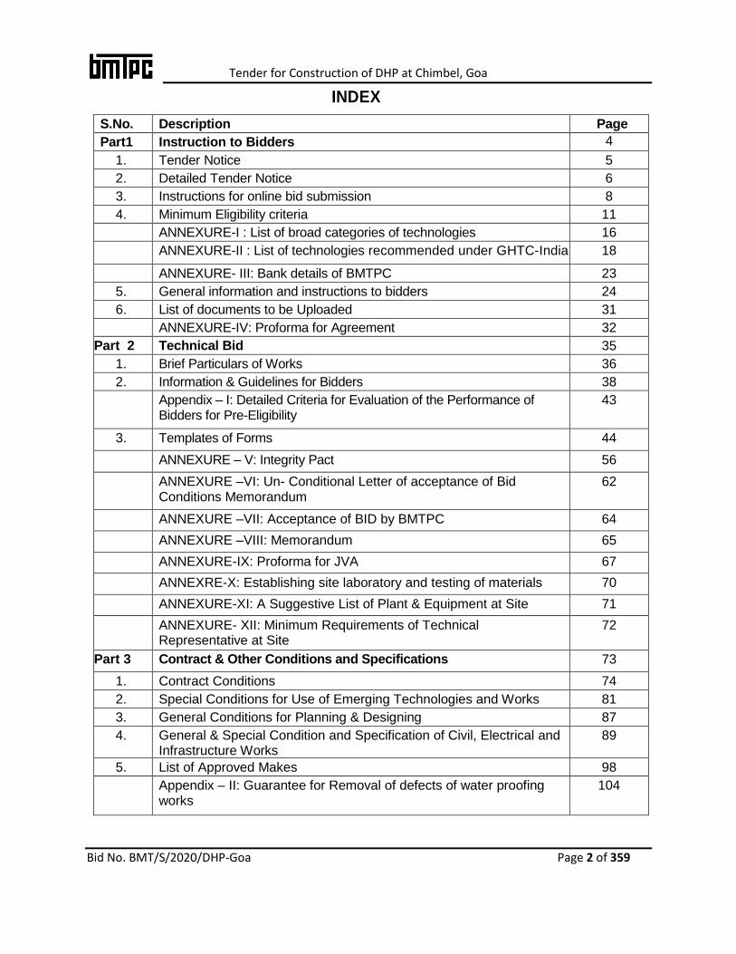
INDEX
S.No. Description Page no.NNoNo
No. Part1 Instruction to Bidders 4
1. Tender Notice 5
2. Detailed Tender Notice 6
3. Instructions for online bid submission 8
4. Minimum Eligibility criteria 11
ANNEXURE-I : List of broad categories of technologies 16
ANNEXURE-II : List of technologies recommended under GHTC-India 18
ANNEXURE- III: Bank details of BMTPC 23
5. General information and instructions to bidders 24
6. List of documents to be Uploaded 31
ANNEXURE-IV: Proforma for Agreement 32
Part 2 Technical Bid 35
1. Brief Particulars of Works 36
2. Information & Guidelines for Bidders 38
Appendix – I: Detailed Criteria for Evaluation of the Performance of Bidders for Pre-Eligibility
43
3. Templates of Forms 44
ANNEXURE – V: Integrity Pact 56
ANNEXURE –VI: Un- Conditional Letter of acceptance of Bid Conditions Memorandum
62
ANNEXURE –VII: Acceptance of BID by BMTPC 64
ANNEXURE –VIII: Memorandum 65
ANNEXURE-IX: Proforma for JVA 67
ANNEXRE-X: Establishing site laboratory and testing of materials 70
ANNEXURE-XI: A Suggestive List of Plant & Equipment at Site 71
ANNEXURE- XII: Minimum Requirements of Technical Representative at Site
72
Part 3 Contract & Other Conditions and Specifications 73
1. Contract Conditions 74
2. Special Conditions for Use of Emerging Technologies and Works 81
3. General Conditions for Planning & Designing 87
4. General & Special Condition and Specification of Civil, Electrical and Infrastructure Works
89
5. List of Approved Makes 98
Appendix – II: Guarantee for Removal of defects of water proofing works
104
Tender for Construction of DHP at Chimbel, Goa
Bid No. BMT/S/2020/DHP-Goa Page 3 of 359
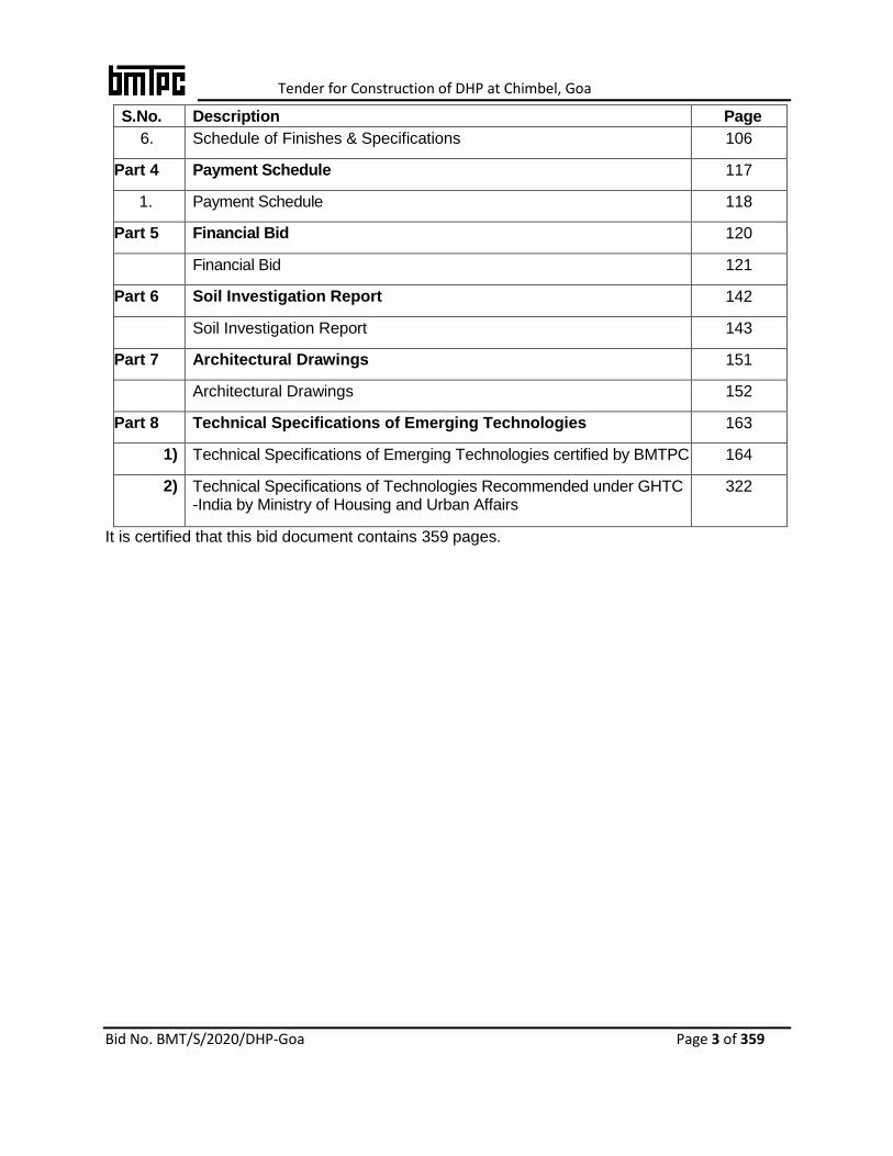
S.No. Description Page no.NNoNo
No. 6. Schedule of Finishes & Specifications 106
Part 4 Payment Schedule 117
1. Payment Schedule 118
Part 5 Financial Bid 120
Financial Bid 121
Part 6 Soil Investigation Report 142
Soil Investigation Report 143
Part 7 Architectural Drawings 151
Architectural Drawings 152
Part 8 Technical Specifications of Emerging Technologies 163
1) Technical Specifications of Emerging Technologies certified by BMTPC
164
2) Technical Specifications of Technologies Recommended under GHTC -India by Ministry of Housing and Urban Affairs
322
It is certified that this bid document contains 359 pages.
Tender for Construction of DHP at Chimbel, Goa
Bid No. BMT/S/2020/DHP-Goa Page 4 of 359
Part-1
Instructions to Bidders

Tender for Construction of DHP at Chimbel, Goa
Bid No. BMT/S/2020/DHP-Goa Page 5 of 359
Building Materials & Technology Promotion Council
Ministry of Housing & Urban Affairs, Government of India Core-5A, 1st Floor, India Habitat Centre, Lodhi Road, New Delhi
Phone: +91-11-24636705, Fax: +91-11-24642849 Website: www.bmtpc.org Email:[email protected]
1. TENDERNOTICE
BMTPC invites online E-Tenders (Two-Bid system) from reputed, experienced, technically and financially sound Technology/system providers (single business entity) and Joint Venture/ consortia of firms / companies (hereafter called Agency) for construction of Construction of Demonstration Housing Project (G+1) for use as Old Age Home on Design & Build basis using emerging technology listed at ANNEXURE – I & ll including onsite infrastructure work at Chimbel, Goa
Location Estimated Project Cost
put to bid (Rs. inLakhs)
Tender Fee (in Rs.) (Non-
refundable)
EMD (Rs.in Lakhs)
Stipulated period of
completion of work
Uploading online bid Document
Last Date for online Submission of
Tender
Technical bid opening
Date Date/Time Date/Time
Chimbel, Goa
554.44 5000 11.09 10.5
Months
03-02-2020 24-02-2020 /
1500 hrs
25-02-2020 /
1500 hrs
1. The Tender document for the work can be seen and downloaded from CPP Portal (https://eprocure.gov.in/eprocure/app). This Tender Document is also available on BMTPC website www.bmtpc.org.
2. The intending bidder must read the terms and conditions of tender carefully. He should only submit his bid if he considers himself eligible and he is in possession of all the documents required.
3. Pre-Bid meeting will be held on 10-02-2020 at 1500 hrs in Conference Room, Building Materials & Technology Promotion Council, Core-5A, 1st Floor, India Habitat Centre, Lodhi Road, New Delhi.
4. Conditional Tender shall not be accepted. 5. Those bidders not registered on the website of eprocure.gov.in, are required to get registered
before hand. If needed they can be imparted training on online bidding process as per details available on the website.
6. The intending bidder must have valid digital signature to submit the bid. 7. Hard copy of online submitted Technical Bid alognwith all documents, proof of online deposited
tender fees, EMD shall be submitted to Executive Director, Building Materials & Technology Promotion Council, Core-5A, 1st Floor, India Habitat Centre, Lodhi Road, New Delhi- 110003 by Courier/post/Hand Delivery on or before 24-02-2020 by 1500 hrs.
8. Corrigendum/ Addendum/ Minutes of Pre-bid Meeting, if any, would appear on the CPP Portal (https://eprocure.gov.in/eprocure/app) and website of BMTPC (www.bmtpc.org) and shall not be published in any “News Paper”.
9. The Executive Director, BMTPC reserves the right to accept or reject any or all tenders without
assigning any reason thereof. This Tender notice shall form a part of contract document.
Executive Director, BMTPC
Tender for Construction of DHP at Chimbel, Goa
Bid No. BMT/S/2020/DHP-Goa Page 6 of 359
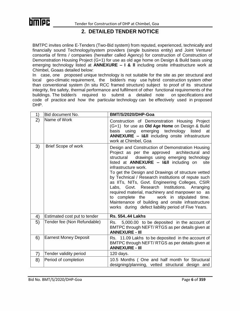
2. DETAILED TENDER NOTICE
BMTPC invites online E-Tenders (Two-Bid system) from reputed, experienced, technically and financially sound Technology/system providers (single business entity) and Joint Venture/ consortia of firms / companies (hereafter called Agency) for construction of Construction of Demonstration Housing Project (G+1) for use as old age home on Design & Build basis using emerging technology listed at ANNEXURE – I & ll including onsite infrastructure work at Chimbel, Goaas detailed below: In case, one proposed unique technology is not suitable for the site as per structural and local geo-climatic requirement, the bidder/s may use hybrid construction system other than conventional system (In situ RCC framed structure) subject to proof of its structural integrity, fire safety, thermal performance and fulfilment of other functional requirements of the buildings. The bidder/s required to submit a detailed note on specifications and code of practice and how the particular technology can be effectively used in proposed DHP.
1) Bid document No. BMT/S/2020/DHP-Goa
2) Name of Work Construction of Demonstration Housing Project (G+1) for use as Old Age Home on Design & Build basis using emerging technology listed at ANNEXURE – I&ll including onsite infrastructure work at Chimbel, Goa
3) Brief Scope of work
Design and Construction of Demonstration Housing Project as per the approved architectural and structural drawings using emerging technology listed at ANNEXURE – I&ll including on site infrastructure work. To get the Design and Drawings of structure vetted by Technical / Research institutions of repute such as IITs, NITs, Govt. Engineering Colleges, CSIR Labs, Govt. Research Institutions. Arranging required material, machinery and manpower so as to complete the work in stipulated time. Maintenance of building and onsite infrastructure works during defect liability period of Five Years.
4) Estimated cost put to tender Rs. 554..44 Lakhs
5) Tender fee (Non Refundable) Rs. 5,000.00 to be deposited in the account of BMTPC through NEFT/ RTGS as per details given at ANNEXURE - IIl
6) Earnest Money Deposit Rs. 11.09 Lakhs to be deposited in the account of BMTPC through NEFT/ RTGS as per details given at ANNEXURE - IIl
7) Tender validity period 120 days.
8) Period of completion 10.5 Months ( One and half month for Structural designing/planning, vetted structural design and

Tender for Construction of DHP at Chimbel, Goa
Bid No. BMT/S/2020/DHP-Goa Page 7 of 359
taking approvals from local authorities + 9 months for construction of building and onsite infrastructure works from the date of handing over the site and all statutory approvals)
9) Last date & Time of online
Submission of tender
24-02-2020 by 1500 hrs.
10) Date of Pre-Bid meeting &Venue 10-02-2020at 1500 hrs.
Conference Room, Building Materials & Technology Promotion Council, Core-5A, 1st Floor, India Habitat Centre, Lodhi Road, New Delhi - 110003.
11) Last date, Time & Place for submission of Hard copy of online submitted Technical Bid along with all documents, proof of online deposited tender fees, EMD.
24-02-2020by 1500 hrs.
Building Materials & Technology Promotion Council, Core-5A, 1st Floor, India Habitat Centre, Lodhi Road, New Delhi -110003.
12) Time & date of online opening of technical bid
25-02-2020, 1500 hrs
13) Time & date of online opening of financial bid of technically qualified bidders
To be intimated later
14) Performance Guarantee Performance Guarantee @ 5% of the tendered amount to be deposited in the account of BMTPC through NEFT/ RTGS as per details given at ANNEXURE–Ill(To be submitted at the time of agreement )
15) Security Deposit (SD) 2.5% of the contract value shall be deducted from the each R.A. Bill till SD reaches 2.5% of the contract value
16) Networth Certificate Minimum 15% of the estimate cost put to tender issued by the certified Chartered Accountant (on the format prescribed in form B
17) Defect liability period 5 (five) years after issue of completion certificate
18) Compensation for delay As per Clauses of Contract
19) Contact office Executive Director, Building Materials & Technology Promotion Council, Core-5A, 1st Floor, India Habitat Centre, Lodhi Road, New Delhi - 110003.
3. INSTRUCTIONS FOR ONLINE BID SUBMISSION
Tender for Construction of DHP at Chimbel, Goa
Bid No. BMT/S/2020/DHP-Goa Page 8 of 359
1) All Bidders are requested to register themselves with the portal http://eprocure.gov.in
and enrol their digital certificate with the user id for participation in the bid.
2) The Bidders are requested to read following conditions in conjunction with
various conditions, wherever applicable appearing with this bid invitation for e-Biding.
The conditions mentioned here in under shall supersede and shall prevail over
the conditions enumerated elsewhere in the bid document.
3) How to submit On-line Bids/Offers electronically against e-Biding?
Bidders are advised to read the following instructions for participating in the electronic bids directly through internet:
i. Late and delayed Bids/Offers after due date/time shall not be permitted in e-Biding system. No bid can be submitted after the last date and time of submission is over. The system time (Indian Standard Time [IST]) that will be displayed on e-biding web page shall be the time and no other time shall be taken into cognizance.
ii. Bidder/s are advised in their own interest to ensure that bids are uploaded in e-biding system well before the closing date and time of bid.
iii. No bid can be modified after the due date for submission of bids. iv. No manual bids/offers along with electronic bids / offers shall be permitted.
4) What is a Digital Signature?
This is a unique digital code which can be transmitted electronically and primarily
identifies a unique sender. The objective of digital signature is to guarantee that the
individual sending the message is who he or she really claims to be just like
the written signature. The Controller of Certifying Authorities of India (CCA)
has authorized certain trusted Certifying Authorities (CA) who in turn allots on a
regular basis Digital Signature Certificates (DSC)
5) Documents which are signed digitally are legally valid documents as per Indian IT
Act (2000).
6) Why is a Digital Signature required?
In order to bid for e-bids all the vendors are required to obtain a legally valid Digital
Certificate as per Indian IT Act from the licensed Certifying Authorities (CA)
operating under the Root Certifying Authority of India (RCAI), Controller of Certifying
Authorities (CCA) of India. The Digital Certificates is issued by CA in the name of a
person authorized for filing Bids/Offers on behalf of his Company. A Bidder can
submit their Bids/Offers on-line only after digitally signing the bid/documents with the
above allotted Digital Signature.

Tender for Construction of DHP at Chimbel, Goa
Bid No. BMT/S/2020/DHP-Goa Page 9 of 359
7) Bidders have to procure Digital Signature Certificate (Class 3 or 2 with signing key
uses) from any of the certifying Authorities in India.
8) Submission of Documents
i. Bidders must submit on line offers by the date and time mentioned in the
tender at the website address stated therein.
ii. E-Bid will provide access to Technical as well as Financial part of bid. Along with
the Technical part, Bidders can attach the required documents listed at page 31
of this bid document along with scan copy of the proof of submission of tender
fee, EMD with the bid in line with the Bid document.
iii. The successful bid submission can be ascertained once acknowledgement is
given by the system through bid submission number after completing all the
process and steps.
iv. The bids have to be submitted online as well as physical submission. However,
documents which necessarily have to be submitted in originals like
Technical Proposal, Proof of submission of Tender fee & EMD and any other
documents mentioned in the bid documents have to be submitted offline.
Financial Bid should not be submitted in a sealed envelope. BMTPC shall not be
responsible in any way for failure on the part of the bidder to follow the
instructions.
v. Financial Bid shall contain only price as per Schedule of Quantities (in form of an
excel sheet) without any condition. The lump sum rate / item rates along with tax
and other components shall be filled up in figures and the total amount shall
be automatically calculated and rounded off to the nearest rupee. It is to be
noted that the Financial Bid shall contain only PRICES and no conditions
whatsoever.
vi. The online bid shall be uploaded through digital signatures by someone
legally authorized to enter into commitment on behalf of the Bidder. The Bidder shall
upload among other documents, Power of Attorney in favour of the
person who is authorized to enter into commitments on behalf of the Bidder.
vii. It is advised that the bidder upload small sized documents at a time
to facilitate in easy uploading into e-biding site. BMTPC does not take any
responsibility in case of failure of the bidder to upload the documents within
specified time of bid submission.
viii. The Bidder(s) shall submit the Technical Bids in the format as mentioned in

Tender for Construction of DHP at Chimbel, Goa
Bid No. BMT/S/2020/DHP-Goa Page 10 of 359
Tender online and also submit its hard copy in sealed envelope and mark the
envelope as “Tender for Construction of Demonstration Housing Project
(G+1) for use as Old Age Home on Design & Build basis using emerging
technologies including onsite infrastructure work at Chimbel, Goa”. The
hardcopy shall be submitted to The Executive Director, Building Materials &
Technology Promotion Council, Core-5A, 1st Floor, India Habitat Centre, Lodhi
Road, New Delhi – 110003 on 24-02-2020 by 1500 hrs and shall clearly mention
name of Project, Bid No. and Bidders details.
ix. The bid shall comprise a sealed single packet containing the online submitted
technical bid along with all documents and proof of online deposited tender fees
& EMD and shall be placed in hard binding and the pages shall be numbered
serially. The document shall clearly mention Name of Bidder and Emerging
Technology proposed. Each page thereof shall be initiated in blue ink by the
authorized signatory. The Bid shall be marked as Original on right hand corner of
Cover page of proposal in Tender in Red ink along with required documents.
Tender for Construction of DHP at Chimbel, Goa
Bid No. BMT/S/2020/DHP-Goa Page 11 of 359
4. MINIMUM ELIGIBILITY CRITERIA
The bidder should meet the following minimum qualifying criteria:
A) Work Experience:
i. Experience of having successfully completed similar works during the last 7
years ending previous day of last date of submission of bids:
a. Three similar works each costing not less than 40% of the estimated cost
put to bid
OR
b. Two similar works each costing not less than 60% of the estimated cost
put to bid
OR
c. One similar work costing not less than 80% of the estimated cost put to bid.
ii. The definition of similar work shall mean construction of “Residential/Non-
Residential buildings using proposed emerging technology/hybrid proposed
technology/any conventional technology.
iii. The past experience in similar nature of work should be supported by certificates
issued by the client’s organization. In case the work experience is of Private
sector the completion certificate shall be supported with copies of Letter of Award
and copies of corresponding TDS certificates. In case of foreign firms, necessary
evidences with respect to taxes may be attached appropriately.
iv. The value of executed works shall be brought to the current level by enhancing
the actual value of work done at a simple rate of 7% per annum, calculated
from the date of completion to previous day of last day of submission of bids.
v. If any information furnished by the Bidder is found incorrect at a later stage, the
bidder shall be liable to be debarred from further bidding and taking works. The
BMTPC reserves the right to verify the contents / particulars furnished by the
bidder independently including inspection of work completed by them.

Tender for Construction of DHP at Chimbel, Goa
Bid No. BMT/S/2020/DHP-Goa Page 12 of 359
B) Certification of the Technology
The emerging technology/proposed structural system of the technology shall be
certified by any of the followings;
1. BMTPC (under its Performance Appraisal Certification
Scheme)
2. CBRI, Roorkee
3. SERC, Chennai
4. Any IIT’s
5. Any NIT’s
6. Any reputed National / International technical institutions.
Necessary valid certificate / document in support of the above shall be submitted along
with the bid.
C) In order to promote MAKE IN INDIA Mission of Govt. of India, the Bidder must
have manufacturing facilities of the proposed technology in India. Bidder has to
provide details such as production capacity of manufacturing unit, complete
address of unit with telephone no., email etc.
D) The purpose of the Demonstration Housing Projects (DHP) is to popularise all
innovative construction technologies available in the country for speedier,
durable and affordable construction. Therefore, each DHP will be executed with
different technology.
E) The technologies which have been selected in earlier two DHP projects i.e. Panchkula,
Haryana (Light Gauge Steel Framed Structure with fibre cement board on both side
and infill of rockwool) and Agartala, Tripura (Stay-in-Place Formwork System- Coffor)
and now a days most commonly used technology in construction i.e. Monolithic
Concrete Construction with Aluminium/ Plastic formwork will not be considered in this
project to have each DHPs with different technologies.
F) BMTPC is inviting two tenders for Demonstration Housing Projects (DHPs)
simultaneously, one at Chimbel, Goa as per this tender and other at Ahmedabad,
Gujarat. The participating agencies are free to participate in the bidding process of
both the DHPs. However, the order for opening of financial bid will be as under:
I) Ahmedabad, Gujarat
II) Chimbel, Goa
G) Once a particular technology has been selected for DHP at Ahmedabad, Gujarat, all
the bids using the same technology for DHP Chimbel, Goa, shall not be opened. This
will ensure that different locations will have separate technologies.
Tender for Construction of DHP at Chimbel, Goa
Bid No. BMT/S/2020/DHP-Goa Page 13 of 359
H) Financial Strength:
i) The Average annual financial turnover of last consecutive fiscal years for last
immediate 5 years shall be at least 50% of the estimated cost put to bid. The
requisite Turnover shall be duly certified by a Chartered Accountant with his
Seal/ signatures and registration number.
ii) Net Worth of the participating agency as on 31stMarch of previous Financial
Year should be positive
iii) Networth of minimum 15% of the ECPT (Estimated Cost Put to Tender) issued by
the certified Chartered Accountant.
iv) The bidder should not have incurred any loss in more than two years during
available last five consecutive balance sheets. The bidder/s are required to
upload and submit page of summarized Balance Sheet (Audited) and also
page of summarized Profit& Loss Account (Audited) for last five years.
I) In case of Joint-venture/consortia of firms/companies:
1) A Consortium of a maximum of 2 (TWO) members (between Technology/System
Provider and Construction Agency) comprising one Lead Member with one
other member shall be allowed and shall hereinafter be referred as "Consortium".
2) The Bidder should submit a Power of Attorney authorizing the signatory of the
application to commit the Bidder.
3) Bids submitted by a Consortium should comply with the following additional
requirements:
a) The number of members in the Consortium would be limited to two (2);
b) The Application should contain the information required from each
member;
c) The Application should include a description of the roles and
responsibilities of all the members;
d) Members of the Consortium shall nominate one member as the Lead
Member and that member must be an entity as defined above;
e) The Bidder who has participated in this bid in its individual capacity
or as part of a Consortium cannot participate as a separate agency
of any other Consortium participating in this bid;
f) The members of the Consortium shall execute a Power of
Attorney for Lead Member of Consortium.
g) The JV will be registered within one month from the date of award of
work.
h) The members of the Consortium shall enter into a Memorandum of

Tender for Construction of DHP at Chimbel, Goa
Bid No. BMT/S/2020/DHP-Goa Page 14 of 359
Understanding (MoU), for the purpose of submission of the bid.
The MoU should, inter alia,
Clearly outline the proposed roles and responsibilities of
each member of the Consortium; and
Include a statement to the effect that all members of the
Consortium shall be liable jointly and severally for the
assignments arising out contract agreement therefore;
A copy of the MoU signed by all members should be
submitted along with the technical bids. The MoU entered into
between the members of the Consortium should contain
the above requirements, failing which the bid shall be considered
non-responsive.
4) A Bidder which has earlier been barred by BMTPC or blacklisted by any State
/UT Government or Central Government / department / agency in India from
participating in Bidding Process shall not be eligible to submit bids,
either individually or as member of a Consortium, if such bar subsists as on the
submission Due Date. The Bidder or consortium shall be required to furnish
an affidavit that there is no such bar imposed and existing as on date.
5) A Bidder or member of Consortium should have, during the last three years,
neither failed to perform on any agreement, as evidenced by imposition of a
penalty or a judicial pronouncement or arbitration award against the Bidder or
member of Consortium, nor been expelled from any project or agreement
nor have had any agreement terminated for breach by such Bidder or member
of Consortium.
6) The Application and all related correspondence and documents should
be furnished by the bidder with the Application may be in any other language
provided that these are accompanied by appropriate translations of the
pertinent passages in the English language by approved/authorized/ licensed
translator. Supporting material, which are not translated into English,
may not be considered. For the purpose of interpretation and evaluation of
the Application, the English language translation shall prevail.
7) Bidder /consortium should be profit making organization. The audited
balance sheet for the last five years maybe attached with the technical bids,
otherwise bids will be rejected.
J) Foreign Work Experience Certificate:
i. In case the work experience is for the work executed outside India, the Bidder
have to submit the completion/experience certificate issued by the owner duly
signed &stamped and affidavit to the correctness of the completion/experience
certificates. The Participating Agency shall also get the

Tender for Construction of DHP at Chimbel, Goa
Bid No. BMT/S/2020/DHP-Goa Page 15 of 359
completion/experience certificates attested by the Indian
Embassy/Consulate/High Commission in the respective country.
ii. In the event of submission of completion /experience certificate by the Bidder
in a language other than English, the English translation of the same
shall be duly authenticated by Chamber of Commerce of the respective country
and attested by the Indian Embassy/Consulate / High Commission in the
respective country.
iii. For the purpose of evaluation of Bidder, the conversion rate of such a currency
into INR shall be the daily representative exchange rate published by the
IMF as on 7 (Seven) days prior to the Last Date of Submission of bid including
extension(s) given if any.

Tender for Construction of DHP at Chimbel, Goa
Bid No. BMT/S/2020/DHP-Goa Page 16 of 359
ANNEXURE – I
LIST OF BROAD CATEGORIES OF TECHNOLOGIES
FORMWORK SYSTEMS – ENGINEERED FORMWORK SYSTEMS
1. Monolithic Concrete Construction with Aluminium/ Plastic formwork (WILL NOT BE
CONSIDERED)
2. Modular Tunnel Form
FORMWORK SYSTEMS -STAY-IN-PLACE FORMWORK SYSTEMS
3. Insulating Concrete Forms
4. Monolithic Insulated Concrete System
5. Stay-in-Place Formwork System- Coffor (WILL NOT BE CONSIDERED)
6. Lost-in-place formwork system- Plaswall Panel system
7. Lost-in-place formwork system- Plasmolite Wall Panels
8. Sismo Building Technology
9. Glass Fibre Reinforced Gypsum Panel System
10. Stay-In-Place PVC Wall Forms
11. Permanent Wall Forms (PVC)
PREFABRICATED SANDWICH PANEL SYSTEM
12. Advanced Building System – EMMEDUE
13. Rapid Panels
14. Reinforced EPS Core Panel System
15. QuickBuild 3D Panels
16. Concrewall Panel System
17. Prefabricated Fibre Reinforced Sandwich Panels
18. Rising EPS (Beads) Cement Panels
19. Flyash EPS (Beads) Cement Sandwich Panels
20. PIR Dry Wall Pre-Fab Panel System
21. Baupanel System
22. V-Infill Wall (Light Weight EPS Wall)
23. Nano Living System Technology
LIGHT GAUGE STEEL STRUCTURAL SYSTEMS
24. Light Gauge Steel Framed Structure with Fibre cement board and rockwool as infill
(WILL NOT BE CONSIDERED)
25. Light Gauge Steel Framed Structure with precast concrete panels on both side of
wall and light weight concrete as infill
PREFABRICATED STEEL STRUCTURAL SYSTEMS
26. Factory Made Fast Track Modular Building System
27. Speed Floor System
28. Continuous Sandwich (PUF) Panels With Steel Structure

Tender for Construction of DHP at Chimbel, Goa
Bid No. BMT/S/2020/DHP-Goa Page 17 of 359
PRECAST CONCRETE CONSTRUCTION SYSTEMS
29. SRPL Building System (Waffle-Crete)
30. Precast Large Concrete Panel System
31. Industrialized 3-S system using RCC precast with or without shear walls, columns,
beams, Cellular Light Weight Concrete Slabs/Semi-Precast Solid Slab
32. Walltec Hollowcore Concrete Panel
33. Robomatic Hollowcore Concrete Wall Panels
34. Urbanaac Precast Construction Technology
35. K-Wall Panels
36. Integrated Hybrid Solution-One (HIS-One)
Tender for Construction of DHP at Chimbel, Goa
Bid No. BMT/S/2020/DHP-Goa Page 18 of 359
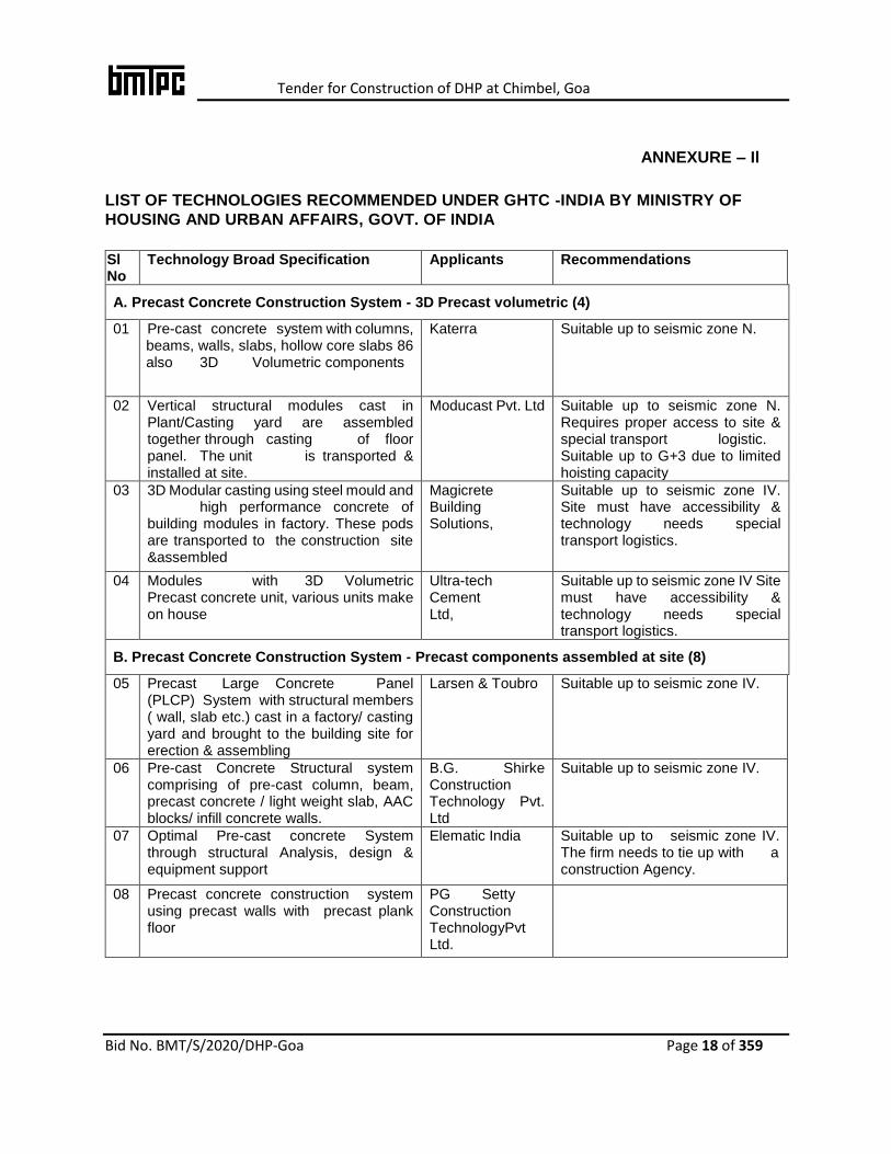
ANNEXURE – Il
LIST OF TECHNOLOGIES RECOMMENDED UNDER GHTC -INDIA BY MINISTRY OF
HOUSING AND URBAN AFFAIRS, GOVT. OF INDIA
Sl No
Technology Broad Specification Applicants Recommendations
A. Precast Concrete Construction System - 3D Precast volumetric (4)
01 Pre-cast concrete system with columns, beams, walls, slabs, hollow core slabs 86 also 3D Volumetric components
Katerra Suitable up to seismic zone N.
02 Vertical structural modules cast in Plant/Casting yard are assembled together through casting of floor panel. The unit is transported & installed at site.
Moducast Pvt. Ltd
Suitable up to seismic zone N. Requires proper access to site & special transport logistic. Suitable up to G+3 due to limited hoisting capacity
03 3D Modular casting using steel mould and high performance concrete of building modules in factory. These pods are transported to the construction site &assembled
Magicrete Building Solutions,
Suitable up to seismic zone IV. Site must have accessibility & technology needs special transport logistics.
04 Modules with 3D Volumetric Precast concrete unit, various units make on house
Ultra-tech Cement Ltd,
Suitable up to seismic zone IV Site must have accessibility & technology needs special transport logistics.
B. Precast Concrete Construction System - Precast components assembled at site (8)
05 Precast Large Concrete Panel (PLCP) System with structural members ( wall, slab etc.) cast in a factory/ casting yard and brought to the building site for erection & assembling
Larsen & Toubro Suitable up to seismic zone IV.
06 Pre-cast Concrete Structural system comprising of pre-cast column, beam, precast concrete / light weight slab, AAC blocks/ infill concrete walls.
B.G. Shirke Construction Technology Pvt. Ltd
Suitable up to seismic zone IV.
07 Optimal Pre-cast concrete System through structural Analysis, design & equipment support
Elematic India Suitable up to seismic zone IV. The firm needs to tie up with a construction Agency.
08 Precast concrete construction system using precast walls with precast plank floor
PG Setty Construction TechnologyPvt Ltd.
Tender for Construction of DHP at Chimbel, Goa
Bid No. BMT/S/2020/DHP-Goa Page 19 of 359
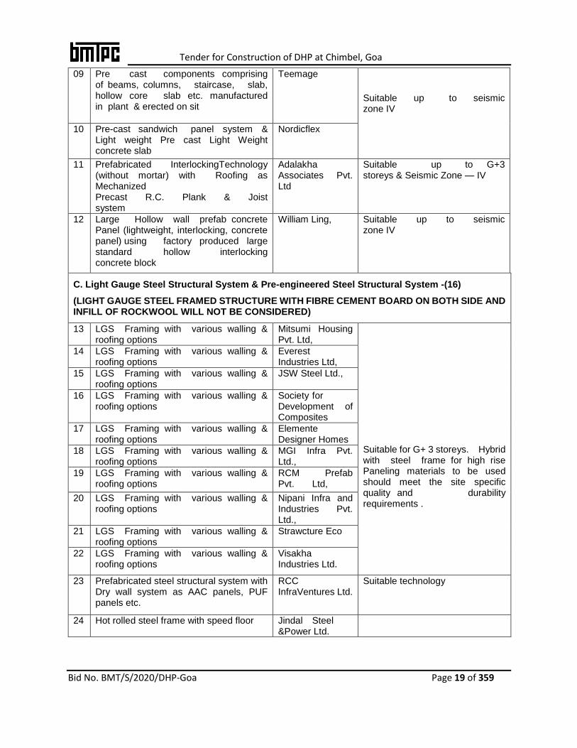
09 Pre cast components comprising of beams, columns, staircase, slab, hollow core slab etc. manufactured in plant & erected on sit
Teemage
Suitable up to seismic zone IV
10 Pre-cast sandwich panel system & Light weight Pre cast Light Weight concrete slab
Nordicflex
11 Prefabricated InterlockingTechnology (without mortar) with Roofing as Mechanized Precast R.C. Plank & Joist system
Adalakha Associates Pvt. Ltd
Suitable up to G+3 storeys & Seismic Zone — IV
12 Large Hollow wall prefab concrete Panel (lightweight, interlocking, concrete panel) using factory produced large standard hollow interlocking concrete block
William Ling,
Suitable up to seismic zone IV
C. Light Gauge Steel Structural System & Pre-engineered Steel Structural System -(16)
(LIGHT GAUGE STEEL FRAMED STRUCTURE WITH FIBRE CEMENT BOARD ON BOTH SIDE AND INFILL OF ROCKWOOL WILL NOT BE CONSIDERED)
13 LGS Framing with various walling & roofing options
Mitsumi Housing Pvt. Ltd,
Suitable for G+ 3 storeys. Hybrid with steel frame for high rise Paneling materials to be used should meet the site specific quality and durability requirements .
14 LGS Framing with various walling & roofing options
Everest Industries Ltd,
15 LGS Framing with various walling & roofing options
JSW Steel Ltd.,
16 LGS Framing with various walling & roofing options
Society for Development of Composites
17 LGS Framing with various walling & roofing options
Elemente Designer Homes
18 LGS Framing with various walling & roofing options
MGI Infra Pvt. Ltd.,
19 LGS Framing with various walling & roofing options
RCM Prefab Pvt. Ltd,
20 LGS Framing with various walling & roofing options
Nipani Infra and Industries Pvt. Ltd.,
21 LGS Framing with various walling & roofing options
Strawcture Eco
22 LGS Framing with various walling & roofing options
Visakha Industries Ltd.
23 Prefabricated steel structural system with Dry wall system as AAC panels, PUF panels etc.
RCC InfraVentures Ltd.
Suitable technology
24 Hot rolled steel frame with speed floor Jindal Steel &Power Ltd.
Tender for Construction of DHP at Chimbel, Goa
Bid No. BMT/S/2020/DHP-Goa Page 20 of 359
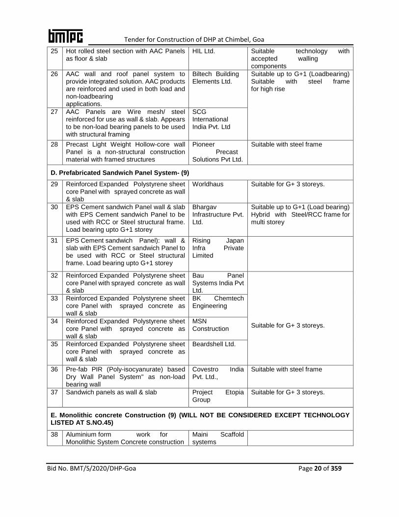
25 Hot rolled steel section with AAC Panels as floor & slab
HIL Ltd. Suitable technology with accepted walling components
26 AAC wall and roof panel system to provide integrated solution. AAC products are reinforced and used in both load and non-loadbearing applications.
Biltech Building Elements Ltd.
Suitable up to G+1 (Loadbearing) Suitable with steel frame for high rise
27 AAC Panels are Wire mesh/ steel reinforced for use as wall & slab. Appears to be non-load bearing panels to be used with structural framing
SCG International India Pvt. Ltd
28 Precast Light Weight Hollow-core wall Panel is a non-structural construction material with framed structures
Pioneer Precast Solutions Pvt Ltd.
Suitable with steel frame
D. Prefabricated Sandwich Panel System- (9)
29 Reinforced Expanded Polystyrene sheet core Panel with sprayed concrete as wall & slab
Worldhaus
Suitable for G+ 3 storeys.
30 EPS Cement sandwich Panel wall & slab with EPS Cement sandwich Panel to be used with RCC or Steel structural frame. Load bearing upto G+1 storey
Bhargav Infrastructure Pvt. Ltd.
Suitable up to G+1 (Load bearing) Hybrid with Steel/RCC frame for multi storey
31 EPS Cement sandwich Panel): wall & slab with EPS Cement sandwich Panel to be used with RCC or Steel structural frame. Load bearing upto G+1 storey
Rising Japan Infra Private Limited
32 Reinforced Expanded Polystyrene sheet core Panel with sprayed concrete as wall & slab
Bau Panel Systems India Pvt Ltd.
Suitable for G+ 3 storeys.
33 Reinforced Expanded Polystyrene sheet core Panel with sprayed concrete as wall & slab
BK Chemtech Engineering
34 Reinforced Expanded Polystyrene sheet core Panel with sprayed concrete as wall & slab
MSN Construction
35 Reinforced Expanded Polystyrene sheet core Panel with sprayed concrete as wall & slab
Beardshell Ltd.
36 Pre-fab PIR (Poly-isocyanurate) based Dry Wall Panel System" as non-load bearing wall
Covestro India Pvt. Ltd.,
Suitable with steel frame
37 Sandwich panels as wall & slab Project Etopia Group
Suitable for G+ 3 storeys.
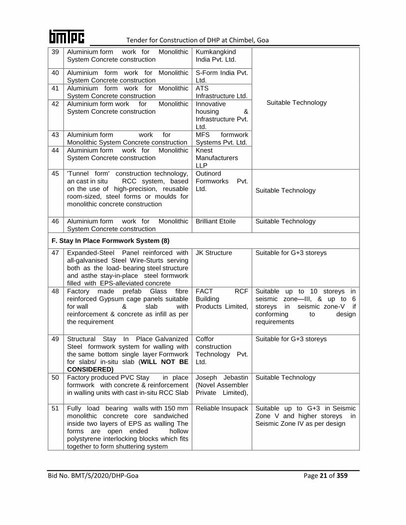
E. Monolithic concrete Construction (9) (WILL NOT BE CONSIDERED EXCEPT TECHNOLOGY LISTED AT S.NO.45)
38 Aluminium form work for Monolithic System Concrete construction
Maini Scaffold systems
Tender for Construction of DHP at Chimbel, Goa
Bid No. BMT/S/2020/DHP-Goa Page 21 of 359
39 Aluminium form work for Monolithic System Concrete construction
Kumkangkind India Pvt. Ltd.
Suitable Technology
40 Aluminium form work for Monolithic System Concrete construction
S-Form India Pvt. Ltd.
41 Aluminium form work for Monolithic System Concrete construction
ATS Infrastructure Ltd.
42 Aluminium form work for Monolithic System Concrete construction
Innovative housing & Infrastructure Pvt. Ltd.
43 Aluminium form work for Monolithic System Concrete construction
MFS formwork Systems Pvt. Ltd.
44 Aluminium form work for Monolithic System Concrete construction
Knest Manufacturers LLP
45 'Tunnel form' construction technology, an cast in situ RCC system, based on the use of high-precision, reusable room-sized, steel forms or moulds for monolithic concrete construction
Outinord Formworks Pvt. Ltd.
Suitable Technology
46 Aluminium form work for Monolithic System Concrete construction
Brilliant Etoile Suitable Technology
F. Stay In Place Formwork System (8)
47 Expanded-Steel Panel reinforced with all-galvanised Steel Wire-Sturts serving both as the load- bearing steel structure and asthe stay-in-place steel formwork filled with EPS-alleviated concrete
JK Structure
Suitable for G+3 storeys
48 Factory made prefab Glass fibre reinforced Gypsum cage panels suitable for wall & slab with reinforcement & concrete as infill as per the requirement
FACT RCF Building Products Limited,
Suitable up to 10 storeys in seismic zone—III, & up to 6 storeys in seismic zone-V if conforming to design requirements
49 Structural Stay In Place Galvanized Steel formwork system for walling with the same bottom single layer Formwork for slabs/ in-situ slab (WILL NOT BE CONSIDERED)
Coffor construction Technology Pvt. Ltd.
Suitable for G+3 storeys
50 Factory produced PVC Stay in place formwork with concrete & reinforcement in walling units with cast in-situ RCC Slab
Joseph Jebastin (Novel Assembler Private Limited),
Suitable Technology
51 Fully load bearing walls with 150 mm monolithic concrete core sandwiched inside two layers of EPS as walling The forms are open ended hollow polystyrene interlocking blocks which fits together to form shuttering system
Reliable Insupack
Suitable up to G+3 in Seismic Zone V and higher storeys in Seismic Zone IV as per design

Tender for Construction of DHP at Chimbel, Goa
Bid No. BMT/S/2020/DHP-Goa Page 22 of 359
52 Ready to use Stay in place polymer formwork, light weight, with flooring slab(combination of ferro -cement and natural stone) placed on RCC precast joists)
Kalzen Realty Pvt. Ltd.
Not suitable as the system presented by the applicant does not qualify as a proven technology. However, it is suitable technology as Stay in place pre -assembled PVC wall forms along with cast in-situ RCC slab.
53 Fast Bloc, Insulated Concrete Form (ICF), acts as formwork for concrete and rebar, Column/post and beam construction, creating an strong skeleton in the walls.
Fast block Building Systems
Suitable up to G+3 in Seismic Zone V and higher storeys in Seismic Zone IV as per design
54 Formwork system "Plaswall" with Two fibre cement boards (FCB) & HIMI (High Impact Molded Inserts) bonded between two sheets of FCB in situ and erected to produce a straight-to-finish wall with in-situ concrete
FTS Buildtech Pvt. Ltd
Suitable up to G+3 in Seismic Zone V and higher storeys in Seismic Zone IV as per design

Tender for Construction of DHP at Chimbel, Goa
Bid No. BMT/S/2020/DHP-Goa Page 23 of 359
ANNEXURE-IIl
BANK DETAILS OF BUILDING MATERIALS & TECHNOLOGY PROMOTION
COUNCIL, NEW DELHI FOR NEFT/RTGS
Name of the Account Holder Building Materials & Technology Promotion
Council, New Delhi
Account No. 62054931366
Bank Name State Bank of India
Bank Address Pragati Vihar, Delhi Branch,
Ground Floor, Core 6, SCOPE Complex, Lodi Road,
New Delhi – 110 003
IFSC Code SBIN0020511
Type of Account Savings
Branch Code 20511
GST No. 07AAATB0304Q1ZW

Tender for Construction of DHP at Chimbel, Goa
Bid No. BMT/S/2020/DHP-Goa Page 24 of 359
5. GENERAL INFORMATION AND INSTRUCTIONSTOBIDDERS
1. The tender document shall be accepted only by E- Tendering on CPP Portal (https://eprocure.gov.in/eprocure/app).
2. The tender document consisting of general specifications to be executed and the set of terms and conditions of the contract to be complied with and other necessary documents can be seen and downloaded from CPP Portal (https://eprocure.gov.in/eprocure/app) and BMTPC website www.bmtpc.org. Those bidders not registered on CPP Portal (https://eprocure.gov.in/eprocure/app) are required to get registered before submitting the tender online.
3. The cost of tender fee will not be refunded under any circumstances.
4. EMD in the form specified in Bid document only shall be accepted.
5. The tender offer shall be valid for 120 days from the last date of submission of Bid.
6. Tender offers without Tender fees& Earnest Money Deposit (EMD) and which do not fulfil all or any of the condition or submitted incomplete in any respect will be rejected.
7. The bidder/s are required to quote strictly as per terms and conditions, specifications, standards of emerging technologies provided in the bid documents and not to stipulate any deviations.
8. The bidder/s are advised to submit complete details with their bids as Technical Bid Evaluation will be done on the basis of documents uploaded on website by the bidder with the bids. The information should be submitted in the prescribed proforma. Bids with Incomplete /Ambiguous information will be rejected.
9. The bidder/s are advised in their own interest to submit their bid documents well in advance from last date/time of submission of bids so as to avoid problems which the bidder may face in submission at last moment /during rush hours.
10. When it is desired by BMTPC to submit revised financial bid within the validity period then it shall be mandatory to submit revised financial bid. If not submitted then the bid submitted earlier shall become invalid and EMD will be forfeited.
11. If the bidder/s is found ineligible after opening of bids, his bid shall become invalid and cost of tender fee shall not be refunded.

Tender for Construction of DHP at Chimbel, Goa
Bid No. BMT/S/2020/DHP-Goa Page 25 of 359
12. Notwithstanding anything stated above, BMTPC reserves the right to assess the capabilities and capacity of the bidder to perform the contract, in the overall interest of BMTPC. In case, bidder capabilities and capacities are not found satisfactory, BMTPC reserves the right to reject the bid.
13. Certificate of Financial Turnover: At the time of submission of bid, the bidder shall upload Affidavit/Certificate from Chartered Accountant mentioning Financial Turnover of last 5 years or for the period as specified in the bid document. There is no need to upload entire voluminous balance sheet. However, one page of summarised balance sheet (Audited) and one page of summarized Profit &Loss Account (Audited) for last 05 years shall be uploaded and submitted in hard copy also.
14. The bidder/s if required, may submit queries, if any, through E-mail and in writing to the bid inviting authority to seek clarifications upto date of pre-bid meeting from the date of uploading of bid document on website. BMTPC will reply to only those queries which are essentially required for submission of bids. BMTPC will not reply to the queries which are not considered fit like replies of which can be implied/found in the NIT/ Bid Documents or which are not relevant or in contravention to NIT/Bid Documents, queries received after 7days from the date of uploading of Bid on website. Technical Bids are to be opened on the scheduled dates. Requests for Extension of opening of Technical Bids will not be entertained.
15. Pre-bid meeting shall be held with the eligible and intending bidder at stated time and venue as mentioned earlier in NIT. As a result of pre-bid meeting, certain modifications may be issued to all eligible bidder/s by BMTPCcorrigendum, if felt necessary. All modifications/addendums/corrigendum issued regarding this bidding process, shall be uploaded on CPP Portal (https://eprocure.gov.in/eprocure/app) and website of BMTPC www.bmtpc.orgonly and shall not be published in any Newspaper.
16. Attending the pre-bid meeting is optional. The Pre-Bid meeting shall be attended by the intending bidder/s only. Further, the intending bidder/s should depute their authorized person with authorization letter in original to attend the pre-bid meeting.
17. All the uploaded documents should be in readable, printable and legible form failing which the Bids shall not be considered for evaluation. The relevant Annexures may be tabled with proper indexing.
18. No Clarification will be sought in case of non-submission of tender fee & EMD of requisite amount or Unconditional letter of acceptance or Affidavit for correctness of document/information. In such cases the bid shall be rejected out rightly without seeking any further clarification/document.
19. All the uploaded and submitted documents shall be considered as duly signed by authorized representative of Bidder.
Tender for Construction of DHP at Chimbel, Goa
Bid No. BMT/S/2020/DHP-Goa Page 26 of 359
20. The bid submitted shall become invalid if:
i. The bidder/s is found ineligible. ii. The bidder/s does not deposit tender fee and EMD with BMTPC iii. The bidder/s does not upload all the documents as stipulated in the
bid document. iv. If any discrepancy is noticed between the documents as uploaded at the time
of submission of bid. v. Bidder/s bid with deviation or conditional bid.
21. UNFAIR ADVANTAGE- Penalty for use of Undue influence: -The bidder/s
undertakes that it has not given, offered or promised to give, directly or indirectly, any gift, consideration, reward, commission, fees, brokerage or inducement to any person in service of the BMTPC or otherwise in procuring the Contracts or forbearing to do or for having done or forborne to do any act in relation to the obtaining or execution of the present Contract or any other Contract with the BMTPC for showing or forbearing to show favour or disfavor to any person in relation to the present Contract or any other Contract with BMTPC. Any breach of the aforesaid undertaking by the bidder/s or any one employed by him or acting on his behalf (whether with or without the knowledge of the bidder/s) or the commission of any offers by the bidder/s or anyone employed by him or acting on his behalf, as defined in Chapter IX of the Indian Penal Code, 1860 or the Prevention of Corruption Act,1986 or any other Act enacted for the prevention of corruption shall entitle the BMTPC to cancel the contract and all or any other contracts with the bidder/s and recover from the bidder/s the amount of any loss arising from such cancellation. A decision of the BMTPC to the effect that a breach of the undertaking had been committed shall be final and binding on the bidder/s. Giving or offering of any gift, bribe or inducement or any attempt at any such act on behalf of the bidder/s towards any officer/employee of the BMTPC or to any other person in a position to influence any officer/employee of the BMTPC for showing any favour in relation to this or any other contract, shall render the bidder/s to such liability/ penalty as the BMTPC may deem proper, including but not limited to termination of the contract, imposition of penal damages, forfeiture of the all type of deposits by the bidder/s and refund of the amounts paid by the BMTPC.
22. Canvassing in connection with the bid are strictly prohibited, and such canvassed bids submitted by the bidder/s will be liable to be rejected and his earnest money shall be absolutely forfeited.
23. The Executive Director BMTPC reserves the right to reject any or all bids or cancel/withdraw the invitation for bid without assigning any reasons whatsoever thereof. No claim of the bidder/s whatsoever shall be entertained on this account.
24. All tendered rates shall be inclusive of all taxes and levies payable under respective statues.
Tender for Construction of DHP at Chimbel, Goa
Bid No. BMT/S/2020/DHP-Goa Page 27 of 359
25. The purpose of the Demonstration Housing Projects (DHP) is to popularise all innovative construction technologies available in the country for speedier, durable and affordable construction. Therefore, each DHP will be executed with different technology.
26. The technologies which have been selected in earlier two DHP projects i.e. Panchkula, Haryana (Light Gauge Steel Framed Structure with fibre cement board on both side and infill of rockwool) and Agartala, Tripura (Stay-in-Place Formwork System- Coffor) and now a days most commonly used technology in construction i.e. Monolithic Concrete Construction with Aluminium/ Plastic formwork will not be considered in this project to have each DHPs with different technologies.
27. BMTPC is inviting two tenders for Demonstration Housing Projects (DHPs) simultaneously, one at Chimbel, Goa as per this tender and other at Ahmedabad, Gujarat. The participating agencies are free to participate in the bidding process of both the DHPs. However, the order for opening of financial will be as under:
I) Ahmedabad, Gujarat
II) Chimbel, Goa
28. Once a particular technology has been selected for DHP at Ahmedabad, Gujarat, all
the bids using the same technology for DHP Chimbel, Goa, shall not be opened. This
will ensure that different locations will have separate technologies.
29. Labour laws to be complied by the selected agency:
i. The selected agency shall obtain a valid license under the Contract Labour (R&A) Act 1970, and the Contract Labour (Regulation and Abolition) Central Rules 1971, before the commencement of the work, and continue to have a valid license until the completion of the work. The selected agency shall also abide by the provisions of the Child Labour (Prohibition and Regulation) Act 1986. Bidder should submit duly signed the undertaking for the same, if not available readily.
ii. The selected agency shall also comply with the provisions of the building and other construction workers (Regulation of Employment & Conditions of Service) Act, 1996 and the building and other construction workers Welfare Cess Act 1996.
30. The amount tendered for the work should be written in English only.
31. Payment to the contractor will be made stage wise as mentioned in part 4 attached with
the bid document.
32. On acceptance of the tender, the name of the accredited representative of the selected agency who will be responsible for taking instructions from the BMTPC’s authorized official shall be communicated to BMTPC in writing.

Tender for Construction of DHP at Chimbel, Goa
Bid No. BMT/S/2020/DHP-Goa Page 28 of 359
33. GST, Labour Cess and any other tax in respect of the contract shall be payable by the contractor and BMTPC will not entertain any claim whatsoever in this respect.
34. The contractor shall keep necessary books of accounts and other documents for the purpose of the condition as may be necessary and shall allow inspection of the same by a duly authorized representative of BMTPC and further shall furnish such other information/document as the authorized representative of BMTPC require.
35. The bidder shall enter in to an Agreement with the BMTPC on Rs. 100 Stamp Paper as per ANNEXURE- IV.
36. The Bidder shall submit only one bid in his name. Submission of any additional bids, for the same work in the name of their partner/associates/group company etc. shall disqualify them.
37. Bidders shall submit PF registration certificate along with tender document.
38. BMTPC reserves the right to engage suitable Project Management Consultant &/or third Party Inspection agency to Engineering Review, monitor & supervise the said work. PMC/TPI will perform its duties as per scope of works /TOR proposed by BMTPC. The selected bidder has to submit all details to PMC.
39. Executive Director, BMTPC reserves the rights to increase /decrease the scope of work and contract without assigning any reason thereof, No claim to that effect shall be entertained.
40. The Bidder shall get the electrical works executed through the authorized Government approved / licensed electrical person or firm in appropriate category in accordance to contractual provisions.
41. The Civil & Electrical works shall be carried out strictly in accordance to the directives issued by the BMTPC.
42. The bidder shall not without the consent in writing of the Executive Director, BMTPC assign or sublet the contract nor make any sub-contract with any person or persons for the execution of the any portion of the work other than for raw materials/ Labour or for any part of the work of which the manufacturers are named on his contract.
43. In case of any dispute or clarification in specification of any tender items the decision of Executive Director, BMTPC shall be final.
44. All the bidders are requested to visit the site. The Cost/rates should be quoted such that expenditure to be done for levelling, removing debris if any, site clearance, retaining wall filling etc. should include in the quoted rate. No extra payment shall be given in any cases.
45. The site of work may be inspected by the bidder or his representative at his own cost. Technical persons of BMTPC may accompany the bidder, if convenient on prior

Tender for Construction of DHP at Chimbel, Goa
Bid No. BMT/S/2020/DHP-Goa Page 29 of 359
intimation. The certificate regarding site visit shall be given by the bidder in the Form – ‘I’.
46. Bidder shall have to make his own arrangements for water and electricity for the purpose of construction work at site at his own expenses.
47. The Bidder, whose tender is accepted, shall be required to furnish by way of Performance Guarantee/Security Deposit for due fulfillment of his contract at the following rate:-
i. Performance Guarantee of 5% (five percent) of the tendered amount to be
deposited in BMTPC account for the proper performance of the Contract Agreement within 15 (Fifteen) days of issue of letter of intent. Maximum allowable 30 days. After 15 days a late fee @0.1% per day of PG amount shall be payable which shall be non-refundable. This amount shall be deposited in the BMTPC Account as per details at ANNEXURE–IIlthrough NEFT/RTGS; Performance guarantee will be released as below: After 2 years of issue of completion certificate -2.0% After 4 years of issue of completion certificate -2.0% After 5 years of issue of completion certificate -1.0 % Provided that there is no defect detected within the said periods.
ii. Security Deposit (SD) @ 2.5% of the tendered value, this shall be recovered from the running bills of the contractor at the rate of 2.5% till total SD reach 2.5%. 50% of the security deposit shall become refundable after successful completion of Maintenance period of 2 years. The remaining 50% of the security deposit shall be released after the completion of defects liability period.
48. The layout plan & architectural drawings of the proposed building (G+1) is attached at
Part 8. The same may slightly deviate as per technology requirement (due to change in thickness of external and internal walls) with the approval of BMTPC. However, the minimum carpet area of various rooms and other provisions including kitchen/pantry, toilet, balcony/verandah and circulation areas such as staircase, corridor/passage need to be maintained as per enclosed drawings in the tender. The Built Up area may vary accordingly.
49. All Bidders are required to quote the rates in financial bid for both the works i.e. building& other provisions and on site Infrastructure works respectively. L1 will be decided after getting the rates for both the works, otherwise, bids will be considered as no-responsive and will be rejected without assigning any reason/s.
50. All the taxes such as TDS etc. as applicable under Govt. of India Rules shall be deducted from the running / final bills of the selected agency.
51. Integrity Pact duly signed by the bidder/s shall be submitted as per ANNEXURE-V. Any bid without signed integrity Pact shall be liable for rejection.
52. The earnest money deposited by all the bidders except the lowest bidder will be

Tender for Construction of DHP at Chimbel, Goa
Bid No. BMT/S/2020/DHP-Goa Page 30 of 359
refunded immediately after the expiry of stipulated bid validity period or immediately after acceptance of the successful bidder, whichever is earlier.
53. The earnest money deposited along with bid by the successful bidder shall be returned after receiving the Performance Guarantee. However, on the written request of the successful bidder, the same may be adjusted against its performance guarantee.
54. In case of any query, please contact on Ph. No. 011-24652416, 24636705 and E- mail: info.bmtpc.org or ska.bmtpc.org / [email protected].
Executive Director
BMTPC
6. LIST OF DOCUMENTS TO BE UPLOADED WITH TECHNICAL BID
Tender for Construction of DHP at Chimbel, Goa
Bid No. BMT/S/2020/DHP-Goa Page 31 of 359
1) Letter of Transmittal 2) Integrity pact duly signed by the bidder (ANNEXURE-V). The Bidder /s are
required to download the Integrity Pact as uploaded in the bid documents, and sign on the same, put rubber stamp/seal and upload the signed copy on e-biding websites.
3) Unconditional Letter of Acceptance of Bid Conditions (in original) mentioned in ANNEXURE-VI(On Letter Head of the bidder)
4) Memorandum as ANNEXURE-VIII. 5) Financial information of Bidder - FORM-A. 6) Networth Certificate duly certified by authorised Chartered Accountant in form B. 7) Details of Similar Works and work Experience Certificates from certified Chartered
Accountant FORM-C and FORM -D 8) Structure and Organization Details of Firm – FORM E 9) Proof of deposited of Tender Fee and EMD Format – FORM F 10) Balance sheet (Audited) and Profit &Loss Account (Audited) for last 05 years of
bidder/s duly certifies by Chartered Accountant. 11) Income tax return of last 5 financial years of bidder (For all parties in case of JV). 12) Form-G of Contract Conditions –Affidavit duly notarized by Notary Public on
Non Judicial Stamp Paper of Rs. 100 for correctness of Documents /Information. 13) Power of Attorney of the person authorized for signing/submitting the bid. 14) Copy of MOU signed by the all members of JV along with Power of Attorney
authorising the signatory of the bid to commit the bidder. 15) Certificate of registration of bidder. 16) Valid GST registration/EPF registration/PAN NO. (For all parties in case of JV). 17) All pages of the entire Corrigendum (if any) duly signed by the authorized person. 18) Pre-bid clarifications, if any. 19) Registration Details of the participating agency as per GST Act in the State
at the location of the Project– Form-H 20) Certificate regarding site visit by the contractor in the FORM – ‘I’ 21) Details of Administrative and Technical staff to be associated in the project 22) Geographical presence of the Bidder 23) Valid License under Contract Labour (R & A) Act 1970 or duly signed undertaking
for obtaining the same , if not readily available. 24) The Valid certificate / document of Technology/Structural System proposed 25) Complete details of proposed technology including specifications. 26) Details of manufacturing facilities of the proposed technology in India. 27) Project brief on approach to design and construction work for this project. 28) Any other documents as deemed fit by bidder.
NOTE: i) All the uploaded documents should be in readable, printable and legible,
failing which the Bids shall not be considered for evaluation. ii) All the above documents duly paginated, signed, indexed and bound in one
volume are also required to be submitted in physical form to BMTPC before last date of submission of bid.
ANNEXURE- IV
PROFORMA FOR AGREEMENT (On Non-Judicial Stamp Paper of Rs. 100)

Tender for Construction of DHP at Chimbel, Goa
Bid No. BMT/S/2020/DHP-Goa Page 32 of 359
THIS AGREEMENT made this ………………………………………………….day of …………………………………………………………………………. between the BMTPC, established under the MoHUA, having its Office at Core 5A, 1st Floor, India Habitat Centre, Lodhi Road, New Delhi – 110003 (which expression shall mean and include its successor or successors in office and assignee) acting through the Executive Director, BMTPC, New Delhi hereinafter called, ‘The Council’ on the one part and M/s/Sri ……………..................... ………………………………………………………….. hereinafter called the “Agency” which expression shall mean and include their heirs, executors, administrators and assignee) on the other part. WHEREAS, BMTPC, is desirous of construction of (NAME OF WORK) (hereinafter referred to as the “PROJECT”) on behalf of the (NAME OF OWNER/MINISTRY) (hereinafter referred to as “OWNER”), had invited tenders as per Tender documents vide NIT No. _____. AND WHEREAS (NAME OF CONTRACTOR) had participated in the above referred tender vide their tender dated _____ and BMTPC has accepted their aforesaid tender and award the contract for (NAME OF PROJECT) on the terms and conditions contained in its Letter of Intent No. ________ and the documents referred to therein, which have been unequivocally accepted by (NAME OF CONTRACTOR) vide their acceptance letter dated _______ resulting into a contract. NOW THEREFORE THIS DEED WITNESSETH AS UNDER: ARTICLE 1.0 – AWARD OF CONTRACT a. SCOPE OF WORK BMTPC has awarded the contract to (NAME OF CONTRACTOR) for the work of (NAME OF WORK) on the terms and conditions in its letter of intent No. __________ dated ________ and the documents referred to therein. The award has taken effect from (DATE) i.e. the date of issue of aforesaid letter of intent. The terms and expressions used in this agreement shall have the same meanings as are assigned to them in the “Contract Documents” referred to in the succeeding Article. ARTICLE 2.0 – CONTRACT DOCUMENTS 2.1 The contract shall be performed strictly as per the terms and conditions stipulated herein
and in the following documents attached herewith (hereinafter referred to as “Contract Documents”). a) BMTPC Notice Inviting Tender No. ________ date ______and BMTPC’s tender
document consisting of: i) ________________________________________________ ii) ______________________________________________ iii) ______________________________________________
b) (NAME OF CONTRACTOR) letter proposal dated ________ and their subsequent
communication:
i. Letter of Acceptance of Tender Conditions dated ______________
Tender for Construction of DHP at Chimbel, Goa
Bid No. BMT/S/2020/DHP-Goa Page 33 of 359
ii. _________________________________________________ iii. _________________________________________________
2.2 BMTPC’s detailed Letter of Intent No. _________ dated ____ including Bill of
Quantities. Agreed time schedule, Contractor’s Organisation Chart and list of Plant and Equipment submitted by Contractor.
2.3 All the aforesaid contract documents referred to in Para 2.1 and 2.2 above shall form
an integral part of this Agreement, in so far as the same or any part thereof column, to the tender documents and what has been specifically agreed to by BMTPC in its Letter of Intent. Any matter inconsistent therewith, contrary or repugnant thereto or deviations taken by the Contractor in its “TENDER” but not agreed to specifically by BMTPC in its Letter of Intent, shall be deemed to have been withdrawn by the Contractor without any cost implication to BMTPC. For the sake of brevity, this Agreement along with its aforesaid contract documents and Letter of Intent shall be referred to as the “Contract”.
ARTICLE 3.0 – CONDITIONS & CONVENANTS 3.1 The scope of Contract, Consideration, terms of payments, advance, security deposits,
taxes wherever applicable, insurance, a greed time schedule, compensation for delay and all other terms and condition contained in BMTPC’s Letter of Intent No. __________ dated _____ are to be read in conjunction with other aforesaid contract documents. The contract shall be duly performed by the contractor strictly and faithfully in accordance with the terms of this contract.
3.2 The scope of work shall also include all such items which are not specifically mentioned
in the Contract Documents but which are reasonably implied for the satisfactory completion.
3.3 Contractor shall adhere to all requirements stipulated in the Contract documents. 3.4 Time is the essence of the Contract and it shall be strictly adhered to. The progress of
work shall conform to agreed works schedule /contract documents and Letter of Intent. 3.5 This agreement constitutes full and complete understanding between the parties and
terms of the presents. It shall supersede all prior correspondence to the extent of inconsistency or repugnancy to the terms and conditions contained in Agreement. Any modification of the Agreement shall be effected only by a written instrument signed by the authorized representative of both the parties.
3.6 The total contract price for the entire scope of this contract as detailed in Letter of Intent
is Rs._________________ (Rupees _____________________________ only), which shall be governed by the stipulations of the contract documents
ARTICLE 4.0 – NO WAIVER OF RIGHTS 4.1 Neither the inspection by BMTPC or the authorized representative of BMTPC or Owner
or any of their officials, employees or agents nor order by BMTPC or the authorized representative of BMTPC for payment of money or any payment for or acceptance of,
Tender for Construction of DHP at Chimbel, Goa
Bid No. BMT/S/2020/DHP-Goa Page 34 of 359
the whole or any part of the work by BMTPC or the authorized representative of BMTPC or any extension of time nor any possession taken by the authorized representative of BMTPC shall operate as waiver of any provisions of the contract, or of any power herein reserved to BMTPC, or any right to damage herein provided, nor shall any waiver of any breach in the contract be held to be a waiver or any other or subsequent breach.
ARTICLE 5.0 – GOVERNING LAW AND JURISDICTION 5.1 The Laws applicable to this contract shall be the laws in force in India and jurisdiction
of Delhi Court (s) only. 5.2 Notice of Default
Notice of default given by either party to the other party under the Agreement shall be in writing and shall be deemed to have been duly and properly served upon the parties hereto, if delivered against acknowledgment due or by FAX or by registered mail duly addressed to the signatories at the address mentioned herein above.
IN WITNESS WHEREOF, the parties through their duly authorized representatives have executed these presents (execution whereof has been approved by the Competent Authorities of both the parties) on the day, month and year first above mentioned at New Delhi.
For and on behalf of: For and on behalf of:
SIGNED AND DELIVERED FOR AND ON BEHALF OF M/s /Shri …………………………………………………… IN THE PRESENCE OF
WITNESS 1. 2.
SIGNED AND DELIVERED FOR AND ON BEHALF OF BUILDING MATERIALS & TECHNOLOGY PROMOTION COUNCIL (BMTPC) IN THE PRESENCE OF
WITNESS 1. 2.

Tender for Construction of DHP at Chimbel, Goa
Bid No. BMT/S/2020/DHP-Goa Page 35 of 359
PART-2
Technical Bid

Tender for Construction of DHP at Chimbel, Goa
Bid No. BMT/S/2020/DHP-Goa Page 36 of 359
1. BRIEF PARTICULARS OF WORK
1. Salient details of the work for which bids are invited are as under:
Name of work Estimated
Project Cost put to bid (Rs. in Lakhs)
Stipulated period of completion of work
Construction of Demonstration Housing Project (G+1) for use as Old Age Home on Design & Build basis using emerging technology listed at Annexure – 1&2 including onsite infrastructure work at Chimbel, Goa
554.44
10.5 Months
2. The site for work has been allotted by Institute of Public Assistance (Provedoria)(IPA), Government of Goa at Chimbel, North Goa.
3. The salient features of the project are as under:
i. DHP consist of G+1 structure
Rooms (single) – 5 nos., rooms (twin sharing) – 2 nos., room (triple sharing) – 1 no., rooms (four sharing) – 4 nos., room (6 sharing) – 1 no., room (7 sharing) – 1 no., room (10 sharing)- 1 no. Other provisions Activity room (1 no.), prayer room (1 no.), dining hall with kitchen (1 no.), reading room (1 no.), doctors room (2 nos.), Physio therapy room (1 no.), emergency care room ( 1 no.), nurses room (1 no.), caretaker room (1 no.) guest room (1 no.), office (1 no.), convenience room ( 1 no.), lift room (1 no.) and separate toilets for ladies & gents, ramp
ii. Plot area for DHP 2000 Sqmt. iii. No. of Floors G+1
iv. Carpet area details of rooms Rooms (single) – 5 nos. (12.47 Sqmt each) Rooms (twin sharing) – 2 nos. (17.2 Sqmt each) Room (triple sharing) – 1 no. (34.4 Sqmt.) Rooms (four sharing) – 4 nos. (48.00 Sqmt. each)
Tender for Construction of DHP at Chimbel, Goa
Bid No. BMT/S/2020/DHP-Goa Page 37 of 359
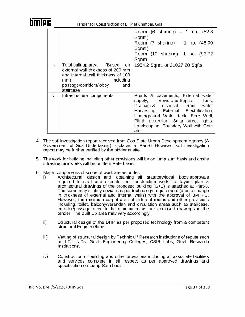
Room (6 sharing) – 1 no. (52.8 Sqmt.) Room (7 sharing) – 1 no. (48.00 Sqmt.) Room (10 sharing)- 1 no. (93.72 Sqmt)
v. Total built up area (Based on external wall thickness of 200 mm and internal wall thickness of 100 mm) including passage/corridors/lobby and staircase
1954.2 Sqmt. or 21027.20 Sqfts.
vi. Infrastructure components
Roads & pavements, External water supply, Sewerage,Septic Tank, Drainage& disposal, Rain water Harvesting, External Electrification, Underground Water tank, Bore Well, Plinth protection, Solar street lights, Landscaping, Boundary Wall with Gate etc.
4. The soil Investigation report received from Goa State Urban Development Agency (A
Government of Goa Undertaking) is placed at Part-6. However, soil investigation report may be further verified by the bidder at site.
5. The work for building including other provisions will be on lump sum basis and onsite infrastructure works will be on Item Rate basis.
6. Major components of scope of work are as under: i) Architectural design and obtaining all statutory/local body approvals
required to start and execute the construction work.The layout plan & architectural drawings of the proposed building (G+1) is attached at Part-8. The same may slightly deviate as per technology requirement (due to change in thickness of external and internal walls) with the approval of BMTPC. However, the minimum carpet area of different rooms and other provisions including, toilet, balcony/verandah and circulation areas such as staircase, corridor/passage need to be maintained as per enclosed drawings in the tender. The Built Up area may vary accordingly.
ii) Structural design of the DHP as per proposed technology from a competent structural Engineer/firms.
iii) Vetting of structural design by Technical / Research institutions of repute such as IITs, NITs, Govt. Engineering Colleges, CSIR Labs, Govt. Research Institutions.
iv) Construction of building and other provisions including all associate facilities and services complete in all respect as per approved drawings and specification on Lump-Sum basis.
Tender for Construction of DHP at Chimbel, Goa
Bid No. BMT/S/2020/DHP-Goa Page 38 of 359
v) Construction of onsite infrastructure works such as earth filling, Roads & pavements, External water supply & Sewerage, Septic Tank, Drainage and disposal, Rain water Harvesting, Underground water tank, Bore well, Plinth protection, External Electrification, Solar street lights, Landscaping, Boundary Wall with entrance gate etc. as per approved drawings and specifications on item rate basis.
vi) Arranging required material, machinery and manpower so as to complete the work in stipulated time.
vii) Maintenance of structure and onsite infrastructure works during defect liability period of Five Years.
7. Work shall be executed according to Clauses of Contract of General Condition of Contract (GCC) of CPWD with upto date amendments mentioned at Part – 3 and schedule of finishes & specifications given in Part -3 of this bid document and CPWD Specification issued by CPWD till the last of submission of bid.
2. INFORMATION AND GUIDELINES FOR BIDDERS
1.0 General:
1.1 Letter of transmittal and forms for deciding eligibility are given at Section 3 (Page No. 44).
1.2 All information called for in the enclosed forms should be furnished against the relevant columns in the forms. If for any reason, information is furnished on a separate sheet, this fact should be mentioned against the relevant column. Even, if no information is to be provided in a column, a ‘nil’ or ‘no such case’ entry should be made in that column. If any particulars/query is not applicable in case of the bidder, it should be stated as ‘Not applicable’. The bidder are cautioned that not giving complete information called for in the application forms or not giving it in clear terms or making any change in the prescribed forms (or) deliberately suppressing the information may result in the bid being summarily disqualified. Bid made by telegram or telex and those received late will not be entertained.
1.3 The bid should be in English. The bidder should sign on each page of application, forms and documents before scanning& uploading and to ensure proper numbering and indexing.
1.4 Corrections if any should be made by neatly crossing out, initialing, dating and rewriting. Pages of the eligibility criteria document are numbered. Additional Sheets if any added by the bidder should also be numbered by him. They should be submitted as a package with signed letter of transmittal. Over writing should be avoided.
1.5 References, information and certificate from the respective clients certifying

Tender for Construction of DHP at Chimbel, Goa
Bid No. BMT/S/2020/DHP-Goa Page 39 of 359
suitability, technical knowledge or capability of the bidder should be signed by an authorized officer.
1.6 The bidder may furnish any additional information, which he thinks is necessary to establish his capabilities to successfully complete envisaged work. He is however advised not to furnish superfluous information. No information shall be entertained after submission of eligibility criteria document unless it is called for by BMTPC.
1.7 If private works are shown in support of eligibility, certified copy of the TDS shall be submitted along with the experience certificate and the TDS amount shall tally with the actual amount of work done.
1.8 All bidder as a single entity or in JV/ Consortium have to meet all eligibility conditions mentioned in bid document comprehensively otherwise bid submitted will be rejected.
2.0 Definitions:
2.1 In this document the following words and expressions have the meaning hereby assigned to them.
2.2 Employer: Means the BMTPC acting through the Executive Director
2.3 Bidder: Means the Technology/system providers (single business entity) and Joint Venture/ consortia of firms / companies (hereafter called Agency)
2.4 “Year” means “Financial Year” unless stated otherwise
3.0 Final Decision Making Authority:
The BMTPC reserves the right to accept or reject any bid and to annul the process and reject all bids at any time without assigning any reason or incurring any liability to the bidder/s.
4.0 Addendum/ Corrigendum
Addendum/Corrigendum to the bid documents may be issued prior to the date of submission of the bid to clarify or effect modification in specification and/or contract terms included in various bid documents. The bidder/s shall suitably take into consideration such Addendum/Corrigendum while submitting his bid. The bidder shall upload / return such Addendum/Corrigendum duly signed and stamped as confirmation of its receipt & acceptance and submit along with the bid document. All Addendum/Corrigendum shall be signed and stamped on each page by the bidder and shall become part of the bid and contract documents.
5.0 Site Visit:
It is incumbent upon the bidder to visit the site at his own cost, and examine it

Tender for Construction of DHP at Chimbel, Goa
Bid No. BMT/S/2020/DHP-Goa Page 40 of 359
and its surroundings by himself collect all information that is considered necessary for proper assessment, planning, design and construction of the project. It is expected that while bidding, the bidder will take utmost care and diligence by visiting the sites and collecting the required parameters necessary. In case of any discrepancies later, BMTPC will not be held responsible.
6.0 Evaluation Criteria:
6.1 The details submitted by the bidder will be evaluated in the following manner:-
6.1.1 The initial criteria prescribed in the bid document in respect of experience of similar work experience, eligibility, net worth and financial strength etc., will first be scrutinized and the bidder/s eligibility for the project will be determined.
6.1.2 The bidder/s qualifying the initial criteria as mentioned above will be evaluated as per the criteria mentioned below by scoring method on the basis of details furnished by the bidder/s-
a. Financial strength (Form ‘A’& ‘B’)- Max.25 marks b. Experience in similar nature of work during last 7 years(Form ‘C’)-
Max.25 marks c. Performance on works (Time over Run) (Form ‘D’) –Max.10 marks d. Performance on works (Quality) (Form ’D’)- Max.20 marks b. Assessment in terms of Technical Competency, plant and
machinery, consulting capabilities, approach to design and construction and work plan– Max 20 marks
------------------------------------------------------------------------------------------------------
Total – 100marks
------------------------------------------------------------------------------------------------------
The Detailed criteria for evaluation of performance of Bidder for Pre-Eligibility is given at Appendix – I
6.1.3 To become eligible for short listing and for opening the Financial Bid, the bidder must secure at least 50% (Fifty percent)marks in each category and 60% (Sixty percent) marks in aggregate.
6.1.4 BMTPC, however reserves the right to restrict the list of such qualified Bidder to any number deemed suitable by it.
6.1.5 After evaluation of Technical Bids, Financial Bids will be opened only of technically qualified bidders as per the criteria defined above and the work will be awarded to the lowest quoted (L1)bidder.
Note: The average value of performance of works for time over run and quality shall be taken on the basis of performance report of the eligible similar works.

Tender for Construction of DHP at Chimbel, Goa
Bid No. BMT/S/2020/DHP-Goa Page 41 of 359
7.0 Financial Information:
Bidder should furnish the following financial information:
i. Annual financial statement for the last Five years in Form ‘A’ and ii. Networth Certificate in form B.
8.0 Experiences in Works Highlighting Experience in Similar Works:
8.1 Bidder should furnish the following:
i. List of all works of similar nature successfully completed during last Seven years in Form ‘C’
ii. Performance reports (corresponding to work mentioned in (Form-C) in Form-D. If needed, the bidder may attach a separate certificate in this regard from performance report issuing authority.
9.0 Organization Information:
9.1 Bidder is required to submit the information in respect of his/her/their organization in Form- ‘E’.
9.1.1 The bidder should have sufficient number of Technical and Administrative employees for proper execution of the contract. The Bidder should have to submit a list of these employees stating clearly how these would be involved in this work within 15 days of award of work.
10.0 Construction Plant and Equipment:
The Bidder should furnish the list of construction plant and equipment required to be used in carrying out the work.
11.0 Letter of Transmittal:
The Bidder should submit the letter of transmittal attached with the document.
12.0 Opening of Financial Bid:
After evaluation of pre-qualification documents, a list of short listed agencies who qualifies in technical bids will be prepared. There after the financial bids of only the
Tender for Construction of DHP at Chimbel, Goa
Bid No. BMT/S/2020/DHP-Goa Page 42 of 359
qualified and technically acceptable bidder shall be opened at the notified time, date and place in the presence of the qualified bidders or their representatives if they desire to be present. The bid shall remain valid for 120 days from the date of opening of Technical bid (eligibility bid).
13.0 Award criteria:
13.1 The BMTPC reserves the right, without being liable for any damages or obligation to inform the bidder to:
13.1.1 Amend the scope and value of contract to the bidder.
13.1.2 Reject any or all the applications without assigning any reason.
13.1.3 Any effort on the part of the bidder or his agent to exercise influence or to pressurize the BMTPC would result in rejection of his bid. Canvassing of any kind is prohibited.

Tender for Construction of DHP at Chimbel, Goa
Bid No. BMT/S/2020/DHP-Goa Page 43 of 359
Appendix - I
Detailed Criteria for Evaluation of the performance of bidders for Pre-Eligibility
S. No
Attributes Max. Marks Evaluation
1 Financial
Strength
(Maximum
25 Marks)
20 Marks 1. a). 60% marks for minimum eligibility criteria
b) 100% marks for twice the minimum eligibility
criteria or more
In between (a) & (b) - on pro-rata basis
05 Marks 2. Minimum 15% of the ECPT issued by the certified Chartered Accountant
2. Past Experience in similar work (Maximum
25 Marks)
25 marks a). 60% marks for minimum eligibility criteria
b) 100% marks for twice the minimum eligibility
criteria or more
In between (a) & (b) - on pro-rata basis
3. Performance on works
[Time Over Run (TOR)]: Maximum 10 marks
Parameter Calculation for points Score Maximum
Marks
If TOR =
(i) Without levy of compensation
(ii) With levy of compensation
(iii) Levy of compensation not
decided
1.00 2.00 3.00 >3.50
10 10 7.5 5 5
10 2.5 0 0
10 5 0 0
TOR = AT/ST, where AT =Actual Time; ST= Stipulated Time.
Note: Marks for value in between the stages indicated above is to be determined by straight line variation basis.
4 Performance of works (Quality): Maximum 20 Marks
(i) Outstanding 20 Marks
(ii) Very Good 15 Marks
(iii) Good 10 Marks
(iv) Poor 0 Marks
5 Assessment in terms of Technical Competency, plant and machinery, consulting capabilities, approach to design and construction with work plan: Max 20 Marks
(Attach the list of technical staffs, existing consultation partners, plant and machinery details, geographical presence and other moveable and immovable assets)
i. Technical staffs, existing consultation partners
05 Marks
ii. Plant and machinery details 05 Marks
iii. Geographical presence and other moveable and immovable assets
05 Marks
iv. Approach to design and construction, work plan based on design philosophy mentioned in scope of work
05 Marks
Grand Total 100 Marks

Tender for Construction of DHP at Chimbel, Goa
Bid No. BMT/S/2020/DHP-Goa Page 44 of 359
3. TEMPLATE OF FORMS
LETTER OF TRANSMITTAL
From:
__________________
__________________
To,
Executive Director,
Building Materials & Technology Promotion Council (BMTPC)
Core 5A, 1st Floor, India Habitat Centre,
Lodhi Road, New Delhi – 110 003
Name of Work: Construction of Demonstration Housing Project (G+1)for use as Old Age Homeon Design & Build basis using Emerging technology including on site Infrastructure Work at Chimble, Goa.
Sir,
Having examined details given in the bid document for the above work, I/we hereby submit the relevant information.
1. I/We hereby certify that all the statements made and information supplied in the enclosed Forms A to J and accompanying statement are true and correct.
2. I/we have furnished all information and details necessary for eligibility and have no further pertinent information to supply.
3. I/we submit the requisite net worth certificate by certified chartered accountant and authorize the……………….to approach the CA issuing the net worth certificate to confirm the correctness thereof. I/We also authorize………………………………to approach individuals, BMTPC, firms and corporation to verify our competence, work experience, and general reputation.
I/we submit the following certificates in support of our suitability, technical knowledge and capability for having successfully completed the following works:
Certificate
It is certified that the information given in the enclosed eligibility bid are correct. It is also certified that I/We shall be liable to be debarred, disqualified/cancellation of enlistment in case any information furnished by me/us found to be incorrect.
Enclosures:
Date of submission
Seal of Bidder& Signature(s) of bidder/s
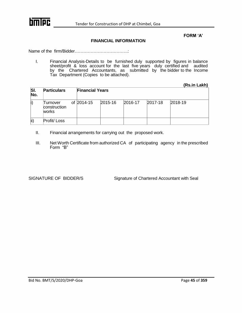
Tender for Construction of DHP at Chimbel, Goa
Bid No. BMT/S/2020/DHP-Goa Page 45 of 359
FORM ‘A’
FINANCIAL INFORMATION
Name of the firm/Bidder……………………………….:
I. Financial Analysis-Details to be furnished duly supported by figures in balance sheet/profit & loss account for the last five years duly certified and audited by the Chartered Accountants, as submitted by the bidder to the Income Tax Department (Copies to be attached).
(Rs.in Lakh)
Sl. No.
Particulars Financial Years
i) Turnover of construction works
2014-15 2015-16 2016-17 2017-18 2018-19
ii) Profit/ Loss
II. Financial arrangements for carrying out the proposed work.
III. Net Worth Certificate from authorized CA of participating agency in the prescribed Form “B”
SIGNATURE OF BIDDER/S Signature of Chartered Accountant with Seal
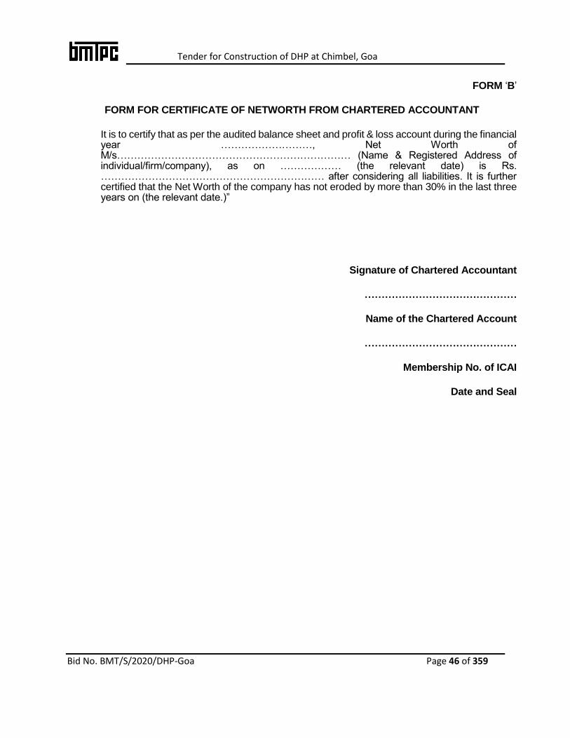
Tender for Construction of DHP at Chimbel, Goa
Bid No. BMT/S/2020/DHP-Goa Page 46 of 359
FORM ‘B’
FORM FOR CERTIFICATE OF NETWORTH FROM CHARTERED ACCOUNTANT
It is to certify that as per the audited balance sheet and profit & loss account during the financial year ………………………, Net Worth of M/s…………………………………………………………… (Name & Registered Address of individual/firm/company), as on ……………… (the relevant date) is Rs. ………………………………………………………… after considering all liabilities. It is further certified that the Net Worth of the company has not eroded by more than 30% in the last three years on (the relevant date.)”
Signature of Chartered Accountant
………………………………………
Name of the Chartered Account
………………………………………
Membership No. of ICAI
Date and Seal

Tender for Construction of DHP at Chimbel, Goa
Bid No. BMT/S/2020/DHP-Goa Page 47 of 359
FORM ‘C’
DETAILS OF ELIGIBLE SIMILAR NATURE OF WORKSCOMPLETED IN LAST SEVEN YEARS ENDING PREVIOUS DAY OF LAST DATE OF SUBMISSION OF BID
Name of the firm/Bidder…………………………….
S.No. Details
1. Name of work/project and location
2. Owner or sponsoring organization
3. Cost of work in Rs. in Crores
4. Date of commencement as per contract
5. Stipulated date of completion
6. Actual date of completion
7. *Litigation/arbitration cases pending/in progress with details
8. Name and Address (Postal & E-mail)/telephone number of officer to whom reference may be made
9. Whether the work was done on back to back basis
Certified that the above list of works is complete and no work has been left out and that the information given is correct to my/our knowledge and belief.
SIGNATURE OF BIDDER/S WITH STAMP
*indicate gross amount claimed and amount awarded by the Arbitrator.

Tender for Construction of DHP at Chimbel, Goa
Bid No. BMT/S/2020/DHP-Goa Page 48 of 359
FORM ‘D’
PERFORMANCE REPORT OF WORKS REFERRED IN FORM-C
1. Name of work/Project & Location
2. Agreement No.
3. Estimated Cost
4. Bided Cost
5. Date of Start
6. Date of completion
i) Stipulated Date of Completion
(as mentioned in work order)
ii) Actual Date of Completion
7. i) Whether case of levy of compensation for delay has been decided or not
Yes/ No.
ii) If decided, amount of compensation levied for delayed completion, if any.
8. Performance Report
1) Quality of Work Outstanding / Very Good / Good / Poor
2) Financial Soundness Outstanding / Very Good / Good /
Poor 3) Technical Proficiency Outstanding / Very Good / Good /
Poor 4) Resourcefulness Outstanding / Very Good / Good /
Poor 5) General Behavior Outstanding / Very Good / Good /
Poor
Dated: Competent Authority
Note: This certificate should be issued by the owner of the project. However, the quality and performance shall be established by the BMTPC by conducting site visits to the selected project sites

Tender for Construction of DHP at Chimbel, Goa
Bid No. BMT/S/2020/DHP-Goa Page 49 of 359
FORM ‘E’
STRUCTURE & ORGANIZATION
1. Name & Address of the Bidder
2. Telephone No. /
Email id /Telex No./Fax No.
3. Legal status of the bidder (attach copies of original document defining the legal status).
a) A Business Entity
b) A Proprietary Firm
c) A Firm in Partnership
d) A Limited Company or
Corporation
4. Particulars of registration with various Government bodies (attach attested photo-copy).
ORGANIZATION/PLACE OF REGISTRATION REGISTRATION No.
1.
2.
3.
5. Names and Titles of Directors& Officers with designation to be concerned with this work.
6. Designation of individuals authorized to act for the organization.
7. Has the bidder or any constituent partner in case of partnership firm, ever abandoned the awarded work before its completion? If so, give name of the project and reasons for abandonment.
8. Has the bidder, or any constituent partner in case of partnership firm/limited company/ joint venture, ever been convicted by the court of law? If so, give details.
9. In which field of Civil Engineering Construction, the bidder has specialization and interest?
10. Any other information considered necessary but not included above.
Signature of bidder/s with stamp
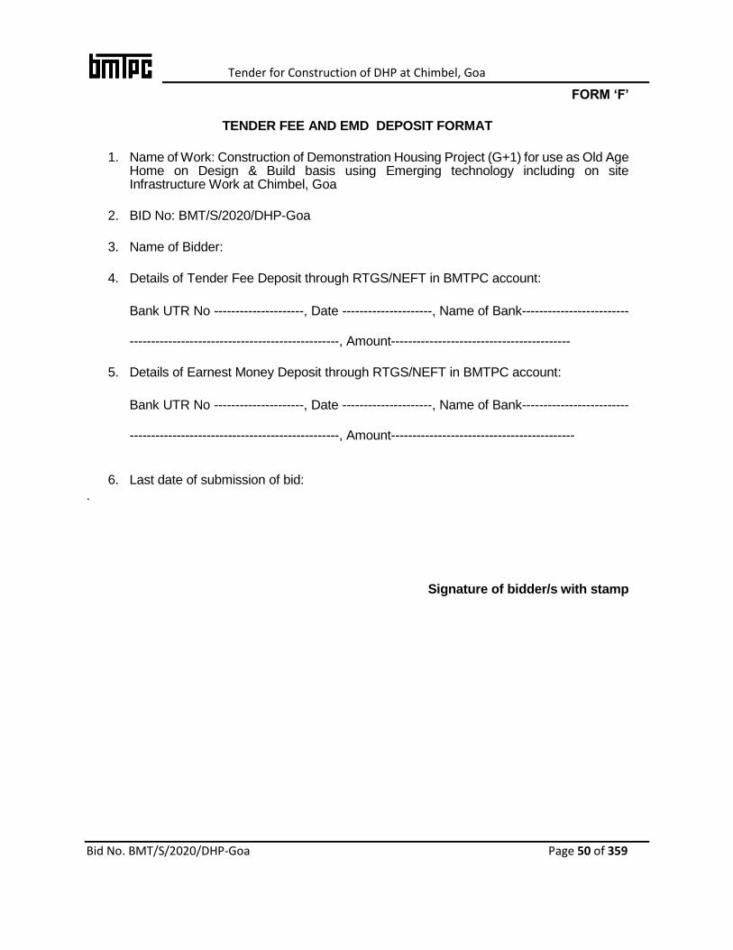
Tender for Construction of DHP at Chimbel, Goa
Bid No. BMT/S/2020/DHP-Goa Page 50 of 359
FORM ‘F’
TENDER FEE AND EMD DEPOSIT FORMAT
1. Name of Work: Construction of Demonstration Housing Project (G+1) for use as Old Age Home on Design & Build basis using Emerging technology including on site Infrastructure Work at Chimbel, Goa
2. BID No: BMT/S/2020/DHP-Goa
3. Name of Bidder:
4. Details of Tender Fee Deposit through RTGS/NEFT in BMTPC account:
Bank UTR No ---------------------, Date ---------------------, Name of Bank-------------------------
-------------------------------------------------, Amount------------------------------------------
5. Details of Earnest Money Deposit through RTGS/NEFT in BMTPC account:
Bank UTR No ---------------------, Date ---------------------, Name of Bank-------------------------
-------------------------------------------------, Amount-------------------------------------------
6. Last date of submission of bid:
.
Signature of bidder/s with stamp

Tender for Construction of DHP at Chimbel, Goa
Bid No. BMT/S/2020/DHP-Goa Page 51 of 359
Form-G
AFFIDAVIT
(To be submitted by bidder on non-judicial stamp paper of Rs.100/(Rupees Hundred only) duly attested by Notary Public)
Affidavit of Mr. ...............................................S/o ............................................. R/o .............................................
I, the deponent above named do hereby solemnly affirm and declare as under:
1. That I am the Proprietor/Authorized signatory of M/s ………………………………….Having its Head Office /Regd.Officeat……………………………………………………
2. That the information/documents/Experience certificates submitted by M/s…………………………. along with the tender for …………………… (Name of work)………… to BMTPC are genuine and true and nothing has been concealed.
3. I shall have no objection in case BMTPC verifies them from issuing authority(ies). I shall also have no objection in providing the original copy of the document(s), in case BMTPC demands so for verification.
4. I hereby confirm that in case, any document, information & / or certificate submitted by me found to be incorrect / false / fabricated BMTPC at its discretion may disqualify / reject / terminate the bid/contract and also forfeit the Tender fee and EMD / All dues.
5. I hereby confirm that our firm /company is not blacklisted/ barred /banned from tendering by BMTPC. If this information is found incorrect, BMTPC at its discretion may disqualify / reject / terminate the bid/contract.
6. The person who has signed the tender documents is our authorized representative. The Company is responsible for all of his acts and omissions in the tender.
I, ....................................., the Proprietor / Authorised signatory of M/s....................................... do hereby confirm that the contents of the above Affidavit are true to my knowledge and nothing has been concealed there from.................... and that no part of it is false.
DEPONENT
Verified at ................this.................day of .....................
DEPONENT
ATTESTED BY (NOTARY PUBLIC)
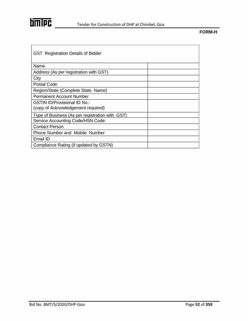
Tender for Construction of DHP at Chimbel, Goa
Bid No. BMT/S/2020/DHP-Goa Page 52 of 359
FORM-H
GST Registration Details of Bidder
Name
Address (As per registration with GST)
City
Postal Code
Region/State (Complete State Name)
Permanent Account Number
GSTIN ID/Provisional ID No.:
(copy of Acknowledgement required)
Type of Business (As per registration with GST)
Service Accounting Code/HSN Code:
Contact Person
Phone Number and Mobile Number
Email ID
Compliance Rating (if updated by GSTN)

Tender for Construction of DHP at Chimbel, Goa
Bid No. BMT/S/2020/DHP-Goa Page 53 of 359
FORM- ‘I’
SITE VISIT CERTIFICATE
(To be submitted on the letter head of Bidder)
I ----------------------------------------------------- authorised representative of M/s ---------------------------------------------------------------------------------- has /have visited the site of the project
Construction of Demonstration Housing Project (G+1) for use as Old Age Home on Design & Build basis using Emerging technology including on site Infrastructure Work at Chimbel, Goa.
We have inspected and evaluated the existing site with reference to its location, soil conditions, sub soil water table, etc. We have submitted this offer after satisfying ourselves about the local conditions, local costs, etc.
Signature of the Tenderer
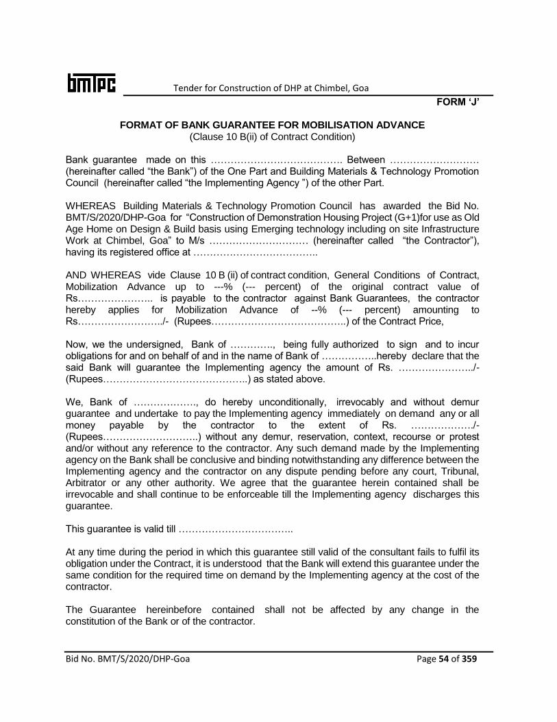
Tender for Construction of DHP at Chimbel, Goa
Bid No. BMT/S/2020/DHP-Goa Page 54 of 359
FORM ‘J’
FORMAT OF BANK GUARANTEE FOR MOBILISATION ADVANCE (Clause 10 B(ii) of Contract Condition)
Bank guarantee made on this …………………………………. Between ……………………… (hereinafter called “the Bank”) of the One Part and Building Materials & Technology Promotion Council (hereinafter called “the Implementing Agency ”) of the other Part. WHEREAS Building Materials & Technology Promotion Council has awarded the Bid No. BMT/S/2020/DHP-Goa for “Construction of Demonstration Housing Project (G+1)for use as Old Age Home on Design & Build basis using Emerging technology including on site Infrastructure Work at Chimbel, Goa” to M/s ………………………… (hereinafter called “the Contractor”), having its registered office at ……………………………….. AND WHEREAS vide Clause 10 B (ii) of contract condition, General Conditions of Contract, Mobilization Advance up to ---% (--- percent) of the original contract value of Rs………………….. is payable to the contractor against Bank Guarantees, the contractor hereby applies for Mobilization Advance of --% (--- percent) amounting to Rs……………………../- (Rupees…………………………………..) of the Contract Price, Now, we the undersigned, Bank of …………., being fully authorized to sign and to incur obligations for and on behalf of and in the name of Bank of ……………..hereby declare that the said Bank will guarantee the Implementing agency the amount of Rs. …………………../- (Rupees……………………………………..) as stated above. We, Bank of ………………., do hereby unconditionally, irrevocably and without demur guarantee and undertake to pay the Implementing agency immediately on demand any or all money payable by the contractor to the extent of Rs. ………………./-(Rupees………………………..) without any demur, reservation, context, recourse or protest and/or without any reference to the contractor. Any such demand made by the Implementing agency on the Bank shall be conclusive and binding notwithstanding any difference between the Implementing agency and the contractor on any dispute pending before any court, Tribunal, Arbitrator or any other authority. We agree that the guarantee herein contained shall be irrevocable and shall continue to be enforceable till the Implementing agency discharges this guarantee. This guarantee is valid till …………………………….. At any time during the period in which this guarantee still valid of the consultant fails to fulfil its obligation under the Contract, it is understood that the Bank will extend this guarantee under the same condition for the required time on demand by the Implementing agency at the cost of the contractor. The Guarantee hereinbefore contained shall not be affected by any change in the constitution of the Bank or of the contractor.

Tender for Construction of DHP at Chimbel, Goa
Bid No. BMT/S/2020/DHP-Goa Page 55 of 359
The neglect or forbearance of the Implementing agency in enforcement of payment of any money, the payment whereof is intended to be hereby secured or the giving of time by the Implementing agency for the payment hereof shall in no way relieve the Bank of their liability under this Deed. The expressions “the Implementing agency”, “the Bank” and “the contractor” hereinbefore used shall include their respective successors and assigns. Notwithstanding anything contained herein: Our liability under this Bank Guarantee shall not exceed Rs………………./- (Rupees…………….) this bank Guarantee shall be valid up to…………………. We are liable to pay the guaranteed amount or any part thereof under this Bank Guarantee only and only if you serve upon us a written claim or demand on or before ……………(date of expiry of Guarantee). In witness whereof we of the Bank have signed and sealed this Guarantee on the …………………day of ………….. being herewith duly authorized. For and on behalf of the Bank of………. Signature of Authorized Bank Official Name: _________________________ Designation _____________________ Stamp/Seal of the bank _______________________ Signed, sealed and delivered for and on behalf of the bank by the above named………….. in the presence of Witness 1 Witness 2 Signature Signature Name Name Address Address
Note:
1. The Bank guarantee should be furnished on stamp paper of value not less than Rs. 100/-.
2. The Stamp paper should have been purchased in the name of the Bank executing the Guarantee.

Tender for Construction of DHP at Chimbel, Goa
Bid No. BMT/S/2020/DHP-Goa Page 56 of 359
ANNEXURE-V
INTEGRITY PACT
To,
Executive Director,
Building Materials & Technology Promotion Council (BMTPC)
Core 5A, 1st Floor, India Habitat Centre,
Lodhi Road, New Delhi – 110 003
Sub: Submission of Bid for the work of Construction of Demonstration Housing Project (G+1) for use as Old Age Home on Design & Build basis using Emerging technology including on site Infrastructure Work at Chimbel, Goa
Dear Sir,
I/We acknowledge that BMTPC is committed to follow the principles thereof as enumerated in the Integrity Agreement enclosed with the bid/bid document.
I/We agree that the Bid document is an invitation to offer made on the condition that I/We will sign the enclosed integrity Agreement, which is an integral part of bid documents, failing which I/We will stand disqualified from the biding process. I/We acknowledge that THE MAKING OF THE BID SHALL BE REGARDED AS AN UNCONDITIONAL AND ABSOLUTE ACCEPTANCE of this condition of the bid.
I/We confirm acceptance and compliance with the Integrity Agreement in letter and spirit and further agree that execution of the said Integrity Agreement shall be separate and distinct from the main contract, which will come into existence when bid/bid is finally accepted by BMTPC. I/We acknowledge and accept the duration of the Integrity Agreement, which shall be in the line with Article 1 of the enclosed Integrity Agreement.
I/We acknowledge that in the event of my/our failure to sign and accept the Integrity Agreement, while submitting the bid/bid, BMTPC shall have unqualified, absolute and unfettered right to disqualify the Bidder/bidder and reject the bid/bid is accordance with terms and conditions of the bid/ bid.
Yours faithfully
(Duly authorized signatory of the Bidder)

Tender for Construction of DHP at Chimbel, Goa
Bid No. BMT/S/2020/DHP-Goa Page 57 of 359
INTEGRITY AGREEMENT
(To be signed by the bidder and same signatory competent /authorized to sign the relevant contract on behalf of BMTPC)
.
This Integrity Agreement is made at ............... on this........... day of ...........20......
BETWEEN
…………………………………………………..……………,
……………………................................................., (Name of Office) BMTPC,
................................................................................................................,
(Hereinafter referred as the ‘Principal/Owner’, which expression shall unless repugnant to the meaning or context hereof include its successors and permitted assigns)
AND
......................................................................................................................
................................................................... (Name and Address of the Individual/firm/Company)
through ...................................................................................................
(Hereinafter referred to as the (Details of duly authorized signatory)
“Bidder/Bidder” and which expression shall unless repugnant to the meaning or context hereof include its success or sand permitted assigns)
Preamble
WHEREAS the Principal / Owner has floated the Bid No……………………….
(hereinafter referred to as “Bid/Bid”) and intends toaward, under laid down organizational procedure, contract for …………………………………………………………..
.................................................................................................................................. (Name of work)
hereinafter referred to as the “Contract”.
AND WHEREAS the Principal/Owner values full compliance with all relevant laws of the land, rules, regulations, economic use of resources and of fairness/transparency in its relation with its bidder/s.
AND WHEREAS to meet the purpose aforesaid both the parties have agreed to enter into this Integrity Agreement (hereinafter referred to as “Integrity Pact” or “Pact”), the terms and conditions of which shall also be read as integral part and parcel of the Bid/Bid documents and Contract between the parties.
NOW, THEREFORE, in consideration of mutual covenants contained in this Pact, the parties hereby agree as follows and this Pact witnesses as under:
Article 1: Commitment of the Principal/Owner
1. BMTPC commits itself to take all measures necessary to prevent corruption and to observe the following principles:

Tender for Construction of DHP at Chimbel, Goa
Bid No. BMT/S/2020/DHP-Goa Page 58 of 359
a) No employee of the Principal/Owner, personally or through any of his/her family members, will in connection with the Bid, or the execution of the Contract, demand, take a promise for or accept, for self or third person, any material or immaterial benefit which the person is not legally entitled to.
b) BMTPC will, during the Bid process, treat all bidder/s with equity and reason. BMTPC will, in particular, before and during the Bid process, provide to all bidder/s the same information and will not provide to any bidder/s)confidential / additional information through which the Bidder/s could obtain an advantage in relation to the Bid process or the Contract execution.
The Principal/Owner shall endeavor to exclude from the Bid process any person, whose conduct in the past has been of biased nature.
2. If BMTPC obtains information on the conduct of any of its employees which is a criminal offence under the Indian Penal code (IPC)/Prevention of Corruption Act, 1988 (PC Act) or is in violation of the principles herein mentioned or if there be a substantive suspicion in this regard, the Principal/Owner will inform the Chief Vigilance Officer/Competent Authority and in addition can also initiate disciplinary actions as per its internal laid down policies and procedures.
Article 2: Commitment of the Bidder/Bidder(s)
1. It is required that each bidder/s(including their respective officers, employees and agents) adhere to the highest ethical standards, and report to the Government / Department all suspected acts of fraud or corruption or Coercion or Collusion of which it has knowledge or becomes aware, during the biding process and throughout the negotiation or award of a contract.
2. The Bidder(s)/Bidder(s) commits himself to take all measures necessary to prevent corruption. He commits himself to obeserve the following principles during his participation in the Bid process and during the Contract execution:
a) The bidder/s) will not, directly or through any other person or firm, offer, promise or give to any of the Principal/Owner’s employees involved in the Bid process or execution of the Contract or to any third person any material or other benefit which he/she is not legally entitled to, in order to obtain in exchange any advantage of any kind whatsoever during the Bid process or during the execution of the Contract.
b) The Bidder(s) will not enter with other bidder/s into any undisclosed agreement or understanding, whether formal or informal. This applies in particular toprices, specifications, certifications, subsidiary contracts, submission or non-submission of bids or any other actions to restrict competitive enessor to cartelize in the bidding process.
c) The Bidder(s) will not commit anyoffence under the relevant IPC/PC Act. Further the bidders/ Contract(s) will not use improperly, (for the purpose ofcompetition or personal gain), or pass on to others, any information or documents provided by the Principal/Owner as part of the business relationship, regarding plans, technical proposals and business details, including information contained or transmitted electronically.
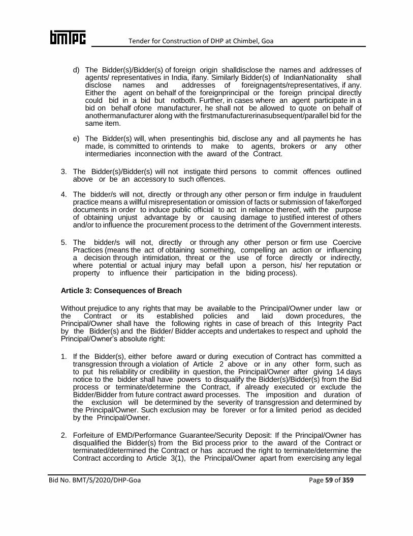
Tender for Construction of DHP at Chimbel, Goa
Bid No. BMT/S/2020/DHP-Goa Page 59 of 359
d) The Bidder(s)/Bidder(s) of foreign origin shalldisclose the names and addresses of agents/ representatives in India, ifany. Similarly Bidder(s) of IndianNationality shall disclose names and addresses of foreignagents/representatives, if any. Either the agent on behalf of the foreignprincipal or the foreign principal directly could bid in a bid but notboth. Further, in cases where an agent participate in a bid on behalf ofone manufacturer, he shall not be allowed to quote on behalf of anothermanufacturer along with the firstmanufacturerinasubsequent/parallel bid for the same item.
e) The Bidder(s) will, when presentinghis bid, disclose any and all payments he has made, is committed to orintends to make to agents, brokers or any other intermediaries inconnection with the award of the Contract.
3. The Bidder(s)/Bidder(s) will not instigate third persons to commit offences outlined above or be an accessory to such offences.
4. The bidder/s will not, directly or through any other person or firm indulge in fraudulent practice means a willful misrepresentation or omission of facts or submission of fake/forged documents in order to induce public official to act in reliance thereof, with the purpose of obtaining unjust advantage by or causing damage to justified interest of others and/or to influence the procurement process to the detriment of the Government interests.
5. The bidder/s will not, directly or through any other person or firm use Coercive Practices (means the act of obtaining something, compelling an action or influencing a decision through intimidation, threat or the use of force directly or indirectly, where potential or actual injury may befall upon a person, his/ her reputation or property to influence their participation in the biding process).
Article 3: Consequences of Breach
Without prejudice to any rights that may be available to the Principal/Owner under law or the Contract or its established policies and laid down procedures, the Principal/Owner shall have the following rights in case of breach of this Integrity Pact by the Bidder(s) and the Bidder/ Bidder accepts and undertakes to respect and uphold the Principal/Owner’s absolute right:
1. If the Bidder(s), either before award or during execution of Contract has committed a transgression through a violation of Article 2 above or in any other form, such as to put his reliability or credibility in question, the Principal/Owner after giving 14 days notice to the bidder shall have powers to disqualify the Bidder(s)/Bidder(s) from the Bid process or terminate/determine the Contract, if already executed or exclude the Bidder/Bidder from future contract award processes. The imposition and duration of the exclusion will be determined by the severity of transgression and determined by the Principal/Owner. Such exclusion may be forever or for a limited period as decided by the Principal/Owner.
2. Forfeiture of EMD/Performance Guarantee/Security Deposit: If the Principal/Owner has disqualified the Bidder(s) from the Bid process prior to the award of the Contract or terminated/determined the Contract or has accrued the right to terminate/determine the Contract according to Article 3(1), the Principal/Owner apart from exercising any legal

Tender for Construction of DHP at Chimbel, Goa
Bid No. BMT/S/2020/DHP-Goa Page 60 of 359
rights that may have accrued to the Principal/Owner, may in its considered opinion forfeit the entire amount of Earnest Money Deposit, Performance Guarantee and Security Deposit of the Bidder/Bidder.
3. Criminal Liability: If the Principal/Owner obtains knowledge of conduct of a Bidder or Bidder, or of an employee or a representative or an associate of a Participating agency or Bidder which constitutes corruption within the meaning of IPC Act, or if the Principal/Owner has substantive suspicion in this regard, the Principal/Owner will inform the same to law enforcing agencies for further investigation.
Article 4: Previous Transgression
1. The bidder/s declares that no previous transgressions occurred in the last 5 years with any other Company in any country confirming to the anticorruption approach or with Central Government or State Government or any other Central/State Public Sector Enterprises in India that could justify his exclusion from the Bid process.
2. If the Bidder makes incorrect statement on this subject, he can be disqualified from the Bid process or action can be taken for banning of business dealings/ holiday listing of the Bidder/Bidder as deemed fit by the Principal/ Owner.
3. If the Bidder/Bidder can prove that he has resorted/recouped the damage caused by him and has installed a suitable corruption prevention system, the Principal/Owner may, at its own discretion, revoke the exclusion prematurely.
Article 5: Equal Treatment of all Participating Agency/Participating agencies/Sub-bidder(s)
1. The Bidder(s)/Bidder(s) undertake(s) to demand from all sub bidder a commitment in conformity with this Integrity Pact. The Bidder/Bidder shall be responsible for any violation(s) of the principles laid down in this agreement/Pact by any of its sub bidder/sub-vendors.
2. The Principal/Owner will enter into Pacts on identical terms as this one with all Bidder and Bidder.
3. The Principal/Owner will disqualify Participating Agency, who do not submit, the duly signed Pact between the Principal/ Owner and the bidder, along with the Bid or violate its provisions at any stage of the Bid process, from the Bid process.
Article 6- Duration of the Pact
This Pact begins when both the parties have legally signed it. It expires for the Bidder/Vendor five years after the completion of work under the contract or till the continuation of defect liability period, whichever is more and for all other Participating Agency, till the Contract has been awarded. If any claim is made/lodged during the time, the same shall be binding and continue to be valid despite the lapse of this Pacts as specified above, unless it is discharged/determined by the Competent Authority, BMTPC.
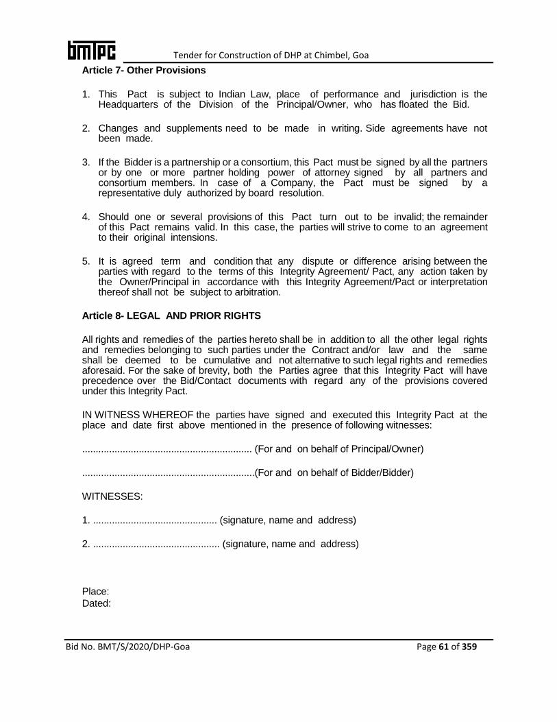
Tender for Construction of DHP at Chimbel, Goa
Bid No. BMT/S/2020/DHP-Goa Page 61 of 359
Article 7- Other Provisions
1. This Pact is subject to Indian Law, place of performance and jurisdiction is the Headquarters of the Division of the Principal/Owner, who has floated the Bid.
2. Changes and supplements need to be made in writing. Side agreements have not been made.
3. If the Bidder is a partnership or a consortium, this Pact must be signed by all the partners or by one or more partner holding power of attorney signed by all partners and consortium members. In case of a Company, the Pact must be signed by a representative duly authorized by board resolution.
4. Should one or several provisions of this Pact turn out to be invalid; the remainder of this Pact remains valid. In this case, the parties will strive to come to an agreement to their original intensions.
5. It is agreed term and condition that any dispute or difference arising between the parties with regard to the terms of this Integrity Agreement/ Pact, any action taken by the Owner/Principal in accordance with this Integrity Agreement/Pact or interpretation thereof shall not be subject to arbitration.
Article 8- LEGAL AND PRIOR RIGHTS
All rights and remedies of the parties hereto shall be in addition to all the other legal rights and remedies belonging to such parties under the Contract and/or law and the same shall be deemed to be cumulative and not alternative to such legal rights and remedies aforesaid. For the sake of brevity, both the Parties agree that this Integrity Pact will have precedence over the Bid/Contact documents with regard any of the provisions covered under this Integrity Pact.
IN WITNESS WHEREOF the parties have signed and executed this Integrity Pact at the place and date first above mentioned in the presence of following witnesses:
............................................................... (For and on behalf of Principal/Owner)
................................................................(For and on behalf of Bidder/Bidder)
WITNESSES:
1. .............................................. (signature, name and address)
2. ............................................... (signature, name and address)
Place:
Dated:

Tender for Construction of DHP at Chimbel, Goa
Bid No. BMT/S/2020/DHP-Goa Page 62 of 359
ANNEXURE-Vl
UNCONDITIONAL LETTER OF ACCEPTANCE OF BID CONDITIONS
(ON THE LETTERHEAD OF THE BIDDER)
Name of Work: Construction of Demonstration Housing Project (G+1) for use as Old
Age Home on Design & Build basis using Emerging technology including on site Infrastructure Work at Chimbel, Goa
i) To be uploaded on website: https://eprocure.gov.in/eprocure/app ii) Tobe opened in the presence of bidders who may be present in the office of
BMTPC.
I/We have read and examined the notice inviting bid, including all documents and amendments up to the last date of submission of bids, clauses of contract, special conditions, bill of quantities & other documents and rules referred to in the contract conditions and all other contents in the bid document for the work. I/We hereby bid for the execution of the work specified for BMTPC within the time specified in …….. viz., schedule of quantities and in accordance in all respect with the specifications, designs, drawing and instructions and contract conditions given in this document. We agree to keep the bid open for one hundred twenty (120) days from the date of opening of technical bid and not to make any modification in its terms and conditions. A copy of receipt of deposit of tender fee and earnest money of Rs 5000/- and Rs.11.09 lakhsrespectivelyinBMTPC account through NEFT/RTGSisscanned and uploaded. If I/We, fail furnish to the prescribed performance guarantee within prescribed period, I/We agree that the said BMTPC or his successors, in office shall without prejudice to any other right orremedy, be at liberty to forfeit the said tender fee and Earnest Money absolutely. Further, if I/We fail to commence work as specified, I/We agree that BMTPC or the successors in office shall without prejudice to any other right orremedy available in law, be at liberty to forfeit the said performanceguarantee absolutely, the said performance guarantee shall be a guaranteeto execute all the works referred to in the bid documents upon the terms andconditions contained or referred to those in excess of that limit at the ratesto be determined in accordance with the provision contained in clause 12.2and 12.3 (as modified) of the bid form. Further, I/We agree that in case of forfeiture of Earnest Money or Performance Guarantee as aforesaid, I/We shall be debarred for participation in the re-bidding process of the work. I/we undertake and confirm that eligible similar work(s) has/have not been got executed through another agency on back to back basis. Further that, if such a violation comes to the notice of Department, then I/we shall be debarred for bidding in BMTPC in future forever. Also, if such a violation comes to the notice of Department before date of start of work, the Competent Authority shall be free to forfeit the entire amount of Earnest Money Deposited/Performance Guarantee. I/We hereby declare that I/We shall treat the bid documents drawings and other records connected with the work as secret/confidential documents and shall not communicate information/derived there from to any person other than a person to whom I/We am/are authorized to communicate the same or use the information in any manner prejudicial to the
Tender for Construction of DHP at Chimbel, Goa
Bid No. BMT/S/2020/DHP-Goa Page 63 of 359
safety of the State. Dated: …………. Signature of Bidder………………. Address: Witness: PostalAddress Occupation: [to be filled by Bidder]

Tender for Construction of DHP at Chimbel, Goa
Bid No. BMT/S/2020/DHP-Goa Page 64 of 359
ANNEXURE-VIl
ACCEPTANCE OF BID BY BMTPC
The above bid (as modified by you as provided in the letters mentioned hereunder) is accepted by me for and on behalf of BMTPC for a sum of Rs.……………….……. (Rupee……….………………………………………………………………………………
……………………………….....………………...).
The letters referred to below shall form part of this contract agreement: -
(a)
(b)
(c)
For & on behalf of BMTPC
Signature ………………………………………
Dated: ………….. Designation ………………………
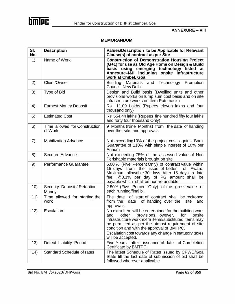
Tender for Construction of DHP at Chimbel, Goa
Bid No. BMT/S/2020/DHP-Goa Page 65 of 359
ANNEXURE – VIIl
MEMORANDUM
Sl. No.
Description Values/Description to be Applicable for Relevant Clause(s) of contract as per Site
1) Name of Work Construction of Demonstration Housing Project (G+1) for use as Old Age Home on Design & Build basis using emerging technology listed at Annexure–I&II including onsite infrastructure work at Chibel, Goa
2) Client/Owner Building Materials and Technology Promotion Council, New Delhi
3) Type of Bid Design and Build basis (Dwelling units and other provisions works on lump sum cost basis and on site infrastructure works on Item Rate basis)
4) Earnest Money Deposit
Rs 11.09 Lakhs (Rupees eleven lakhs and four thousand only)
5) Estimated Cost
Rs 554.44 lakhs (Rupees fine hundred fifty four lakhs and forty four thousand Only)
6) Time allowed for Construction of Work
9 Months (Nine Months) from the date of handing over the site and approvals.
7) Mobilization Advance Not exceeding10% of the project cost against Bank Guarantee of 110% with simple interest of 10% per Annum
8) Secured Advance Not exceeding 75% of the assessed value of Non Perishable materials brought on site
9) Performance Guarantee 5.00 % (Five Percent Only) of contract value within 15 days from the issue of Letter of Award. Maximum allowable 30 days. After 15 days a late fee @0.1% per day of PG amount shall be payable which shall be non-refundable.
10) Security Deposit / Retention
Money
2.50% (Five Percent Only) of the gross value of each running/final bill.
11) Time allowed for starting the work
The date of start of contract shall be reckoned from the date of handing over the site and approvals.
12) Escalation No extra Item will be entertained for the building work and other provisions.However, for onsite infrastructure work extra items/substituted items may be permitted as per the utmost requirement of site condition and with the approval of BMTPC.
Escalation cost towards any change in statutory taxes will be accepted.
13) Defect Liability Period Five Years after issuance of date of Completion Certificate by BMTPC.
14) Standard Schedule of rates The latest Schedule of Rates issued by CPWD/Goa State till the last date of submission of bid shall be followed wherever applicable
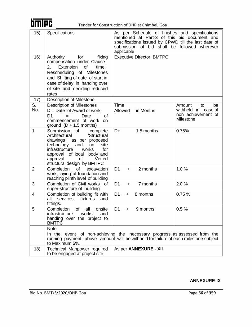
Tender for Construction of DHP at Chimbel, Goa
Bid No. BMT/S/2020/DHP-Goa Page 66 of 359
15) Specifications As per Schedule of finishes and specifications mentioned at Part-3 of this bid document and specifications issued by CPWD till the last date of submission of bid shall be followed wherever applicable
16) Authority for fixing compensation under Clause-
2, Extension of time,
Rescheduling of Milestones
and Shifting of date of start in
case of delay in handing over
of site and deciding reduced
rates
Executive Director, BMTPC
17) Description of Milestone
S. No.
Description of Milestones
D = Date of Award of work
D1 = Date of commencement of work on ground (D + 1.5 months)
Time
Allowed in Months
Amount to be withheld in case of non achievement of Milestone
1 Submission of complete Architectural /Structural drawings as per proposed technology and on site infrastructure works for approval of local body and approval of Vetted structural design by BMTPC
D+ 1.5 months 0.75%
2 Completion of excavation work, laying of foundation and reaching plinth level of building
D1 + 2 months 1.0 %
3 Completion of Civil works of super-structure of building
D1 + 7 months 2.0 %
4 Completion of building fit with all services, fixtures and fittings.
D1 + 8 months 0.75 %
5 Completion of all onsite infrastructure works and handing over the project to BMTPC
D1 + 9 months 0.5 %
Note:
In the event of non-achieving the necessary progress as assessed from the running payment, above amount will be withheld for failure of each milestone subject to Maximum 5%.
18) Technical Manpower required to be engaged at project site
As per ANNEXURE - XIl
ANNEXURE-lX
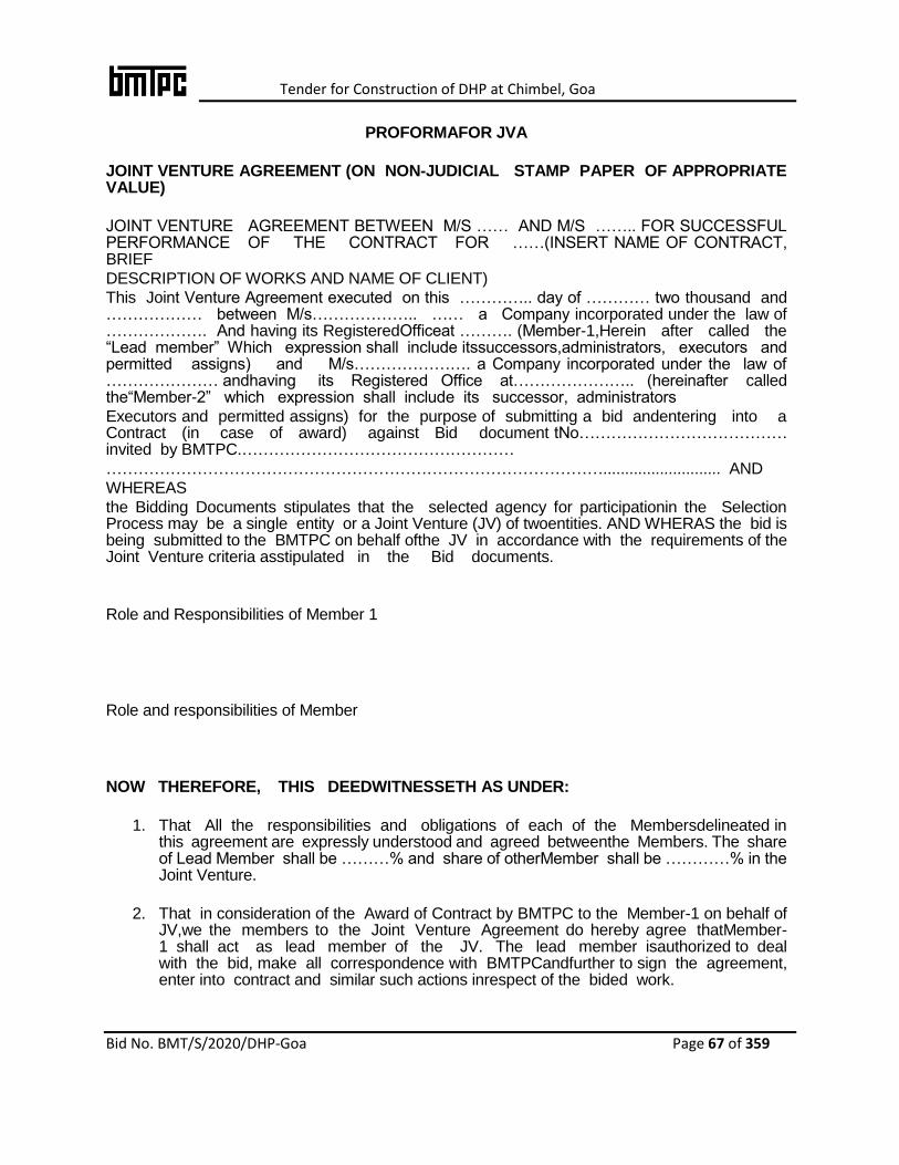
Tender for Construction of DHP at Chimbel, Goa
Bid No. BMT/S/2020/DHP-Goa Page 67 of 359
PROFORMAFOR JVA
JOINT VENTURE AGREEMENT (ON NON-JUDICIAL STAMP PAPER OF APPROPRIATE VALUE)
JOINT VENTURE AGREEMENT BETWEEN M/S …… AND M/S …….. FOR SUCCESSFUL PERFORMANCE OF THE CONTRACT FOR ……(INSERT NAME OF CONTRACT, BRIEF
DESCRIPTION OF WORKS AND NAME OF CLIENT)
This Joint Venture Agreement executed on this ………….. day of ………… two thousand and ……………… between M/s……………….. …… a Company incorporated under the law of ………………. And having its RegisteredOfficeat ………. (Member-1,Herein after called the “Lead member” Which expression shall include itssuccessors,administrators, executors and permitted assigns) and M/s…………………. a Company incorporated under the law of ………………… andhaving its Registered Office at………………….. (hereinafter called the“Member-2” which expression shall include its successor, administrators
Executors and permitted assigns) for the purpose of submitting a bid andentering into a Contract (in case of award) against Bid document tNo………………………………… invited by BMTPC.……………………………………………
…………………………………………………………………………………........................... AND
WHEREAS
the Bidding Documents stipulates that the selected agency for participationin the Selection Process may be a single entity or a Joint Venture (JV) of twoentities. AND WHERAS the bid is being submitted to the BMTPC on behalf ofthe JV in accordance with the requirements of the Joint Venture criteria asstipulated in the Bid documents.
Role and Responsibilities of Member 1
Role and responsibilities of Member
NOW THEREFORE, THIS DEEDWITNESSETH AS UNDER:
1. That All the responsibilities and obligations of each of the Membersdelineated in this agreement are expressly understood and agreed betweenthe Members. The share of Lead Member shall be ………% and share of otherMember shall be …………% in the Joint Venture.
2. That in consideration of the Award of Contract by BMTPC to the Member-1 on behalf of JV,we the members to the Joint Venture Agreement do hereby agree thatMember-1 shall act as lead member of the JV. The lead member isauthorized to deal with the bid, make all correspondence with BMTPCandfurther to sign the agreement, enter into contract and similar such actions inrespect of the bided work.

Tender for Construction of DHP at Chimbel, Goa
Bid No. BMT/S/2020/DHP-Goa Page 68 of 359
3. The lead member which shall represent the JV in all the dealings withBMTPC shall be solely and severally responsible for performance of theentire contract for and on behalf of any or both the members of the JointVenture.
4. JVA shall be valid during the entire currency of the contract including theperiodofextension, if any. Both the members of the JV shall remainassociated with the project till completion of the project. There shall besignificant technical contribution of both the members for the project.However, after completion of the project, lead member shall be solelyresponsible for all responsibilities and liabilities of JV.
5. Once the bid is submitted, the JVA shall not be modified/altered/terminated during the validity of the bid. In case any member of the JV fails to observe /comply with this stipulation, the full Earnest Money Deposit (EMD) shall be liable to be forfeited. Similarly, after the contract is awarded, the constitution of JV shall not be allowed to be altered during the currency of contract. Failure to observe this stipulation shall be deemed to be the breach of contract with all contractual consequences.
6. No member of the JV shall have the right to assign or transfer the interestright or liability in respect of contract without the written consent of theother member and that of BMTPC.
7. In case of any breach of this Contract committed by any of the Members oftheJointVenture Agreement, both the Members do hereby undertake,declareandConfirm that both the members shall be solely and severally responsible forPerformance of the works in accordance with the terms and conditions of theNIT, for the work ofBid Document and/or Contract and undertake to carry out all the obligations andresponsibilities under this Joint Venture Agreement.
8. If the owner sustains any loss or damage on account of any breach of the contract, the lead member of Joint Venture undertake to pay such loss/damages, caused to the BMTPC on its written demand without any demur, reservation, contest or protest in any manner whatsoever. This is without prejudice to any rights of the BMTPC against the Joint Venture/lead member under the contract and/or guarantees.
9. We agree that this Agreement shall be without any prejudice to the various liabilities of the Joint Venture Members including the performance security as well as other obligations of Joint Venture members in terms of the contract.
10. The Joint Venture members will be fully governed by the terms and conditions of the contract and shall be responsible for the quality of all the works and timely execution thereof to meet the completion schedule under the contract.
11. This Agreement shall be construed and interpreted in accordance with the Laws of India and the respective courts of India shall have exclusive jurisdiction to adjudicate upon the disputes between the parties.
12. We, the Joint Venture members agree that this Agreement shall be irrevocable and shall form an integral part of the Contract. We further agree that this agreement shall
Tender for Construction of DHP at Chimbel, Goa
Bid No. BMT/S/2020/DHP-Goa Page 69 of 359
continue to be enforceable till the successful completion of contract and till the BMTPC discharges it.
13. On award of contract, a single Performance Bank Guarantee shall be submitted by the lead member on behalf of JV as per bid conditions.
14. This Agreement shall not be construed as establishing or giving effect to any legal entity such as, a company, a partnership, etc. It shall relate solely towards BMTPC/the BMTPC for submission of Bid/Bid and relatedexecution of works to be performed pursuant to the contract and shall not extend to any other activities.
15. That this Agreement shall be operative from the effective date of the contract.
IN WITNESS WHEREOF, the Joint Venture members through their authorizedRepresentatives have executed these presents and affixed common seal oftheir respective companies, on the day, month and year first mentionedabove.
For M/s …………(Joint Venture- Lead Member)
Witness: 1. …………………… ………………………….
For M/s …………(Joint Venture Member-2)
Witness: 1. ……………………

Tender for Construction of DHP at Chimbel, Goa
Bid No. BMT/S/2020/DHP-Goa Page 70 of 359
ANNEXURE-X
ESTABLISHING SITE LABORATORY AND TESTING OF MATERIALS
(as per Proposed Technology)
Equipment for conducting necessary tests shall be provided and installed at site in the well-furnished site laboratory by the agency at its own cost to establish that the work is being done as per contract specifications and standards. It is also suggested thatsite laboratory need to be kept at Standard Atmospheric Temperature and humidity.
List of Laboratory & Testing Equipment
1.
2.
3.
4.
5.
Note: Tests can also be carried out by the agency at NABL accredited Laboratory with the prior approval of Competent Authority in BMTPC.
Tender for Construction of DHP at Chimbel, Goa
Bid No. BMT/S/2020/DHP-Goa Page 71 of 359
ANNEXURE-Xl
A SUGGESTIVE LIST OF PLANT AND EQUIPMENT AT SITE
(As per Proposed Technology)- to be provided by the Selected agency
The plant and equipment as required for the technology are to be provided by selected agency here.
List of Plant & Equipment at site
1.
2.
3.
4.
5.
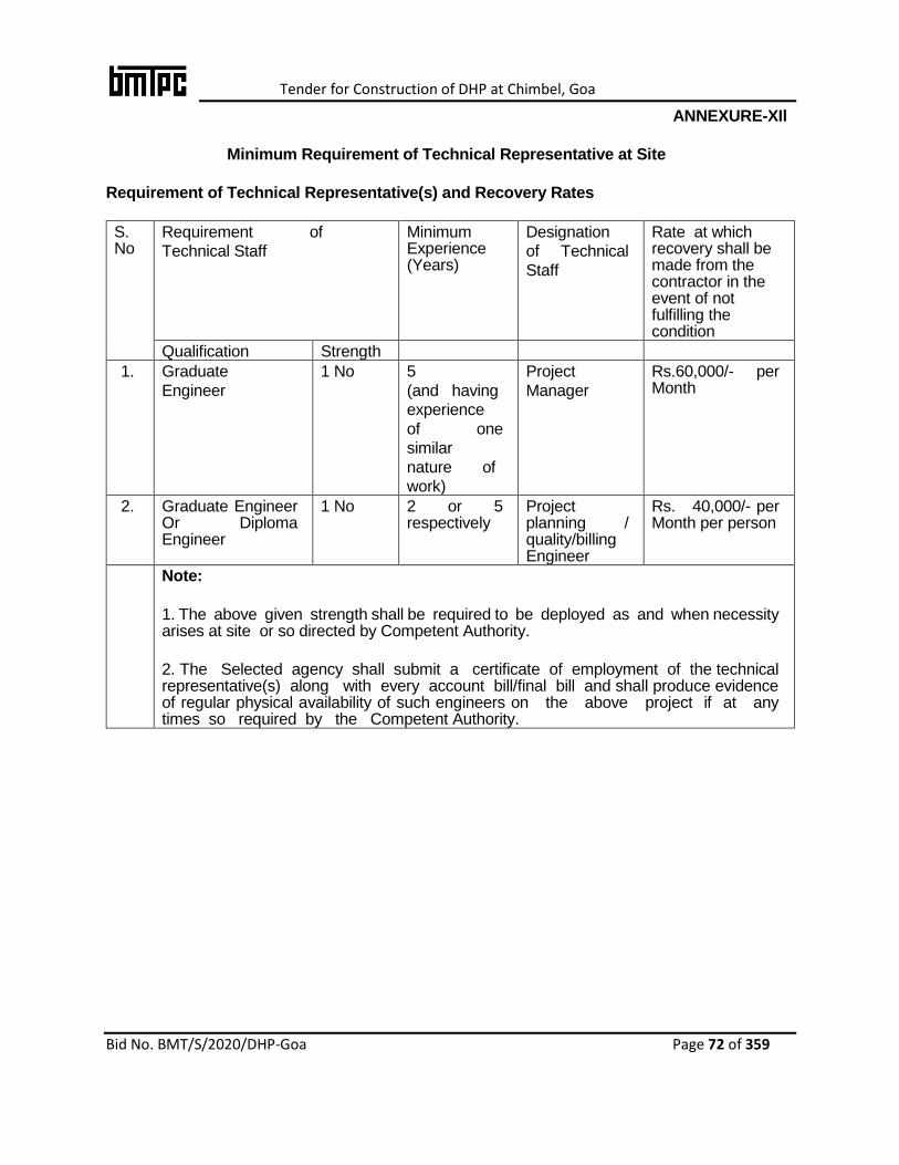
Tender for Construction of DHP at Chimbel, Goa
Bid No. BMT/S/2020/DHP-Goa Page 72 of 359
ANNEXURE-XIl
Minimum Requirement of Technical Representative at Site
Requirement of Technical Representative(s) and Recovery Rates
S. No
Requirement of
Technical Staff
Minimum Experience (Years)
Designation
of Technical
Staff
Rate at which recovery shall be made from the contractor in the event of not fulfilling the condition
Qualification Strength
1. Graduate
Engineer
1 No 5
(and having
experience
of one
similar
nature of
work)
Project
Manager
Rs.60,000/- per Month
2. Graduate Engineer Or Diploma Engineer
1 No 2 or 5 respectively
Project planning / quality/billing Engineer
Rs. 40,000/- per Month per person
Note:
1. The above given strength shall be required to be deployed as and when necessity arises at site or so directed by Competent Authority.
2. The Selected agency shall submit a certificate of employment of the technical representative(s) along with every account bill/final bill and shall produce evidence of regular physical availability of such engineers on the above project if at any times so required by the Competent Authority.
Tender for Construction of DHP at Chimbel, Goa
Bid No. BMT/S/2020/DHP-Goa Page 73 of 359
Part-3
Contract & Other Conditions and Specifications

Tender for Construction of DHP at Chimbel, Goa
Bid No. BMT/S/2020/DHP-Goa Page 74 of 359
1. CONTRACT CONDITIONS (As per General Condition of Contract 2014 of CPWD with up to date Amendments)
A. DEFINITIONS
The Contract means the documents forming the bid and acceptance thereof and the formal agreement executed between the competent authority on behalf of Building Materials and Technology Promotion Council (BMTPC), and the selected agency, together with the documents referred to therein including these conditions, the specifications, designs, drawings and instructions issued from time to time by BMTPC and all these documents taken together, shall be deemed to form one contract and shall be complementary to one another.
1.1 Building Materials and Technology Promotion Council, hereinafter called 'BMTPC' propose to get the works executed as mentioned in the Contract as Implementing /Executing Authority.
1.2 In the contract, the following expressions shall, unless the context otherwise requires, have the meanings, hereby respectively assigned to them: -
a. BMTPC shall means Building Materials and Technology Promotion Council with its office at Core 5A, 1st Floor, India Habitat Centre, Lodhi Road, New Delhi - 110003 or its Administrative officers or other employees authorized to deal with any matter with which these persons are concerned and authorized on its behalf.
b. COMPETENT AUTHORITY means the Executive Director, BMTPC.
c. APPROVAL means approved in writing including subsequent written confirmation of previous verbal approval.
d. SCHEDULE OF QUANTITIES means the complete quantity statement forming or Schedule of Quantities forming part of the bid.
e. SELECTED AGENCY shall mean the individual, firm, LLP or company, whether incorporated or not, undertaking the works and shall include the legal personal representative of such individual or the persons composing such firm or LLP or company, or the successors of such firm or company and the permitted assignees of such individual, firm or company.
f. CONTRACT VALUE means the sum for which the bid is accepted as per the letter of Award.
g. DRAWINGS mean the drawings referred to in the contract document including modifications if any and such other drawings as may from time to time be furnished and/ or approved by BMTPC.
h. DATE OF COMMENCEMENT OF WORK: The date of start of contract shall be reckoned from the date of handing over of site and approvals.
i. LANGUAGE: All documents and correspondence in respect of this contract
Tender for Construction of DHP at Chimbel, Goa
Bid No. BMT/S/2020/DHP-Goa Page 75 of 359
shall be in English Language.
j. “LETTER OF AWARD” shall mean BMTPC’s letter or notification conveying its acceptance of the bid subject to such conditions as may have been stated therein.
k. MONTH means English Calendar month ‘Day’ means a Calendar day of 24 Hrs each.
l. OWNER/CLIENT means the BMTPC, who will be entering into the contract and getting the work executed.
m. SITE means the lands and other places on, under, in or through which the works are to be executed or carried out and any other lands or places provided by BMTPC or used for the purpose of the contract.
n. BID means the Selected agency’s priced offer to BMTPC for the execution and completion of the work and the remedying of any defects therein in accordance with the provisions of the Contract, as accepted by the Letter of Award or Award letter. The word BID is synonymous with Bid and the word BID DOCUMENTS with “Biding Documents” or “offer documents”.
o. WRITING means any manuscript typed, written or printed statement under or over signature and/or seal as the case may be.
p. Works or Work shall unless there be something either in the subject or context repugnant to such construction, be construed and taken to mean the works by or by virtue of the contract contracted to be executed whether temporary or permanent, and whether original, altered, substituted or additional.
q. Headings in the clauses/conditions of bid documents is for convenience only and shall not be used for interpretation of the clause/condition.
r. Words imparting the singular meaning only also include the plurals and vice versa where the context requires. Words importing persons or parties shall include firms and corporations and organizations having legal capacities.
s. Excepted Risk are risks due to riots (other than those on account of selected agency’s employees), war (whether declared or not) invasion, act of foreign enemies, hostilities, civil war, rebellion revolution, insurrection, military or usurped power, any acts of Government, damages from aircraft, acts of God, such as earthquake, lightening and unprecedented floods, and other causes over which the selected agency has no control and accepted as such by the BMTPC.
t. Market Rate shall be the rate as decided by the Competent Authority on the basis of the prevailing cost of materials and labour at the site where the work is to be executed plus the percentage mentioned elsewhere in the bid document to cover, all overheads and profits.
B. CLAUSES OF CONTRACT

Tender for Construction of DHP at Chimbel, Goa
Bid No. BMT/S/2020/DHP-Goa Page 76 of 359
Clause 1.0 Performance Guarantee
Applicable with following modifications:
The selected agency shall deposit an Performance Guarantee of 5% (Five percent) of the contract amount in addition to other deposits mentioned elsewhere in the contract for his proper performance of the contract agreement, (not withstanding and/or without prejudice to any other provisions in the contract) within 15 (fifteen) days from the date of issue of letter of acceptance.Maximum allowable 30 days. After 15 days a late fee @0.1% per day of PG amount shall be payable which shall be non-refundable.This Performance guarantee shall be deposited in BMTPC account through NEFT/ RTGS. After recordinof the completion certificate for the work by the competent authority, the Performance Guarantee shall be returned to the selected agency, without any interest in following manner.
After 2 years of issue of completion certificate -2.0% After 4 years of issue of completion certificate -2.0% After 5 years of issue of completion certificate -1.0 % Provided that there is no defect detected within the said periods.
Clause 1A Recovery of Security Deposit
Applicable with following modifications
50% of the security deposit shall become refundable after successful completion of Maintenance period of 2 years without any interest. The remaining 50% of the security deposit shall be released after the completion of defects liability period without any interest.
Clause 2.0 Compensation for Delay
Applicable
Clause 2A. Incentive for early completion
Applicable
Clause 3.0 When Contract can be Determined
Applicable
Clause 3A Applicable
Clause 4.0 Selected agency liable to pay Compensation even if action not taken under Clause 3 In any case in which any of the powers conferred upon the Competent
Applicable
Clause 5.0 Time and Extension for Delay
Applicable
Clause 6.0 Measurements of Work Done
Applicable
Tender for Construction of DHP at Chimbel, Goa
Bid No. BMT/S/2020/DHP-Goa Page 77 of 359
Clause 6A Computerized Measurement Book
Applicable
Clause 7.0 Payment on Intermediate Certificate to be regarded as advances
& 7A Applicable
Clause 8.0 Completion Certificate and Completion Plans
& 8B Applicable
Clause 9.0 Payment of Final Bill
Applicable
Clause 9A Payment of Selected agency’s Bills to Banks
Payments payable to selected agency may, if so desired by him, be made to agency’s bank account.
Clause 10 Materials supplied by Government
Not-Applicable
Clause 10A Materials to be provided by the selected agency
Applicable
Clause 10B (i) Secured Advance on Non-perishable Materials
Applicable
Clause 10 B (ii) Mobilization Advance
Applicable
Clause 10 B (iii) Plant Machinery & Shuttering Materials Advance
Not-Applicable
Clause 10 B (iv) Interest and recovery
Applicable
Clause 10C, 10CA & 10CC
Not applicable
Clause 10D
Applicable
Clause 11.0 Work to be executed in Accordance with Specifications, Drawings and Orders etc.
Applicable
Clause 12.0 Deviations/ Variations Extent and Pricing
No extra Item/s will be entertained for the building and other provisions, work. However, for onsite infrastructure work extra items/substituted items may be
Tender for Construction of DHP at Chimbel, Goa
Bid No. BMT/S/2020/DHP-Goa Page 78 of 359
permitted as per the utmost requirement of site condition and with the approval of BMTPC. The clause 12 will be applicable for only on site infrastructure works.
Clause 13.0 Foreclosure of contract due to Abandonment or Reduction in Scope of Work
Applicable
Clause 14.0 Carrying out part work at risk & cost of selected agency
Applicable
Clause 15.0 Suspension of Work
Applicable
Clause 16.0 Action in case Work not done as per Specifications
Applicable
Clause 17.0 Selected agency Liable for Damages, defects during defect liability period
Applicable
Clause 18.0 Selected agency to Supply Tools & Plants etc.
Applicable
Clause 18A Recovery of Compensation paid to Workmen
Applicable
Clause 18B Ensuring Payment and Amenities to Workers
Applicable
Clause 19.0 Labour Laws to be complied by the selected agency
Applicable
Clause 20.0 Minimum Wages Act to be complied with
Applicable
Clause 21.0 Work not to be sublet. Action in case of insolvency
Applicable
Clause 22.0 Compensation
Applicable
Clause 23.0 Changes in firm’s Constitution to be intimated
Applicable
Clause 24.0 Applicable
Clause 25.0 Settlement of Disputes & Arbitration
Applicable
Tender for Construction of DHP at Chimbel, Goa
Bid No. BMT/S/2020/DHP-Goa Page 79 of 359
Clause 26.0 Bidder to indemnify Govt. Against Patent Rights
Applicable
Clause 28.0 Action where no Specifications are specified
Applicable
Clause 29.0 Withholding and lien in respect of sum due from selected agency
Applicable
Clause 29A Lien in respect of claims in other Contracts
Applicable
Clause 30.0 Non- Applicable
Clause 31.0 Arrangement of water for construction
Applicable
Clause 36.0 Employment of Technical Staff and employees as per Annexure-XI
Applicable
Clause 37.0 Levy/Taxes payable by selected agency
Applicable
Clause 38.0 Conditions for reimbursement of levy/taxes if levied after receipt of bids
Applicable
Clause 39.0 Termination of Contract on death of selected agency
Applicable
Clause 40.0 If relative working in BMTPC then the selected agency not allowed to bid
Applicable
Clause 41.0 No Engineer to work as Contractor with one of retirement
Applicable
Clause 43.0 Compensation during war like situations
Applicable
Clause 44.0 Apprentices Act provisions to be complied with
Applicable
Clause 45.0 Release of Security deposit after labour clearance
Applicable
Note:
i. In General Condition of Contract (GCC)-2014 with amendments, wherever, President of

Tender for Construction of DHP at Chimbel, Goa
Bid No. BMT/S/2020/DHP-Goa Page 80 of 359
India / Director General / Chief Engineer/ Superintending Engineer appears it will be meant as Executive Director, BMTPC.
ii. In place of Government / Technical examiner it will be BMTPC in this case.
iii. “Applicable” or “Not Applicable” mentioned means that relevant clause/s will be followed or will not be followed respectively as per clauses of General Condition of Contract (GCC)-2014 of CPWD with up to dateamendments.
Tender for Construction of DHP at Chimbel, Goa
Bid No. BMT/S/2020/DHP-Goa Page 81 of 359
2. SPECIAL CONDITIONS FOR USE OF EMERGING TECHNOLOGIES AND WORKS
1. The bidder shall use “Emerging Technology” which have been given in Annexure I &II of this bid document. The emerging technology/ proposed structural system of the technology shall be certified by any of the followings;
a) BMTPC (under its Performance Appraisal Certification Scheme)
b) CBRI, Roorkee
c) SERC, Chennai
d) Any IIT’s
e) Any NIT’s
f) Any reputed National / International technical institutions.
Necessary valid certificate /document in support of the above shall be submitted along with the bid.
2. In case, one proposed unique technology is not suitable for the site as per structural and local geo-climatic requirement, the bidder/s may use hybrid construction system other than conventional system (In situ RCC framed structure) subject to proof of its structural integrity, fire safety, thermal performance and fulfillment of other functional requirements of the buildings. The bidder/s required to submit a detailed note on specifications and code of practice and how the particular technology can be effectively used in proposed DHP.
3. It will be the responsibility of the bidder to establish that the proposed technology is worth adopting for this work and shall provide value addition in respect of quality and time.
4. The bidder shall provide detailed specifications and execution methodology to be adopted for the execution of the work. The bidder shall support the proposal along with the details where this technology has been successfully used in the prescribed proforma given in this bid. The bidder shall make their own sufficient arrangements for visit to the site at own expense.
5. The bidder shall be responsible for the performance of the technology used and buildings constructed by using this. If bidderfails to complete the work with the proposed technology then bidder shall be liable to complete the work by using other technology/s as suggested by Competent Authority. The cost incurred in doing so shall be borne by the bidder completely.
6. The bidder shall engage professionals with experience of proposed technology as per list mentioned in ANNEXURE-XII.
7. All necessary measures like thermal comfort, fire-fighting provisions, natural light and ventilation, etc. shall be taken by the bidder to provide as per NBC 2016 and as defined in Scope of work earlier in the bid document.
8. The necessary suggestions if any, given by the CompetentAuthorityfor carrying out the construction work withemergingtechnology shall
Tender for Construction of DHP at Chimbel, Goa
Bid No. BMT/S/2020/DHP-Goa Page 82 of 359
be incorporated by the bidder for which nothing extra shall be payable.
9. The bidder shall submit the list of laboratories equipment for test and locations of the same along with the proposal of technology. The decision of Competent Authorityshall be final in this matter.
10. The bidder shall provide the list and numbers of T&P/ equipment etc. likely to be used for completing the work. The bidder shall engage the same during the execution.
11.0 Project Management
11.1 The Selected Agency shall prepare the phase wise (monthly) resource chart (materials, manpower and machinery) based on the project execution schedule as mentioned in contract conditions.
11.2 The Selected Agency shall submit the photographs & videos of progress of work on fortnightly basis to make it possible to create a short film of the entire execution of the work to be kept in archive.
11.3 Selected Agency shall submit a detailed monthly progress & program report to the Competent Authority.
11.4 The Selected agency shall stick to the construction schedule, if there is any hindrance or delay due to any reason the same shall be mitigated through engaging extra manpower, material and machinery.
11.5 In order to bring efficiency, transparency & better accessibility, the selected Agency shall also implement the integrated project management & supervision through one of the project Management Software Systems available in the market. The selected Agency shall purchase the Software system at its own cost. The agency shall ensure successful uploading and day to day functioning of Software System till completion / closure of the project, by providing & feeding all necessary data/ entries, seeking online approval from BMTPC.
12.0 Contract Coordination Procedures, Coordination Meetings and Progress
Reporting
The selected agency shall prepare and finalize in consultation with BMTPC, a detailed contract coordination procedure within 15 days from the date of issue of Letter of Award for the purpose of execution of the contract. The selected agency shall have to attend all the meetings at his own cost with BMTPC or consultants of BMTPC during the period of the contract, as and when required and fully cooperate with such personal and agencies involved during these discussions.
a) The project would be evaluated and documented by reputed technical Institution such as IIT/NIT/ Government engineering college. The cost of such evaluation will be borne by BMTPC.

Tender for Construction of DHP at Chimbel, Goa
Bid No. BMT/S/2020/DHP-Goa Page 83 of 359
b) The selected agency will facilitate any visits by such Technical Institutes and provide necessary data
13.0 Organization of Sensitization / Capacity Building Programme/s
BMTPC will organize need based sensitization / capacity building programme/s at project site/ other place on new / alternate technologies for the benefit of working professionals and local construction workforce in the region. The cost of such programme/s will be borne by BMTPC. The selected agency will fully cooperate in successful organization of such programme/s.
14.0 Defect liability:
The contractor’s liability during the defect liability period of five years from the final date of completion shall be limited to rectification of defects including replacement as follows
Sr. No.
Description Defect Liability
i. Proposed structural system alongwith Walls and roof of building using proposed technology
Rectification of all structural/non-structural defects to ensure structural integrity of the building.
ii. Concrete a) Rectification of structural / superficial / non-structural cracks.
b) Rectification of dampness / seepage in roof slab / junctions & sunken portion.
c) Rectification of cracks in beam, shade, column.
iii. Walls as per proposed technology / Brick work
a) Rectification of cracks in panel wall / portion.
b) Cracks / settlement of dwarf walls. c) Rectification of efflorescence.
iv. Joinery a) Replacement of warped joinery.
b) Cracks in panels, rails / styles etc.
v. Building Hardware a) Repairs / Replacement of loosened / pre-mature failure of fittings.
b) Tightening / Replacement of sag in mosquito proof net.
vi. Steel & Iron work a) Rectification / Replacement of defective part of pressed steel door frames, rolling shutter.
b) Redoing of defective portion in fabrication / welding including painting.
c) Grills, gates etc. – defects to be rectified.
vii. UPVC windows Rectification / Replacement of defective parts
viii. Roof treatment Rectification of leakage / seepage of roof slab including covering at junction till guarantee period.
Tender for Construction of DHP at Chimbel, Goa
Bid No. BMT/S/2020/DHP-Goa Page 84 of 359
ix. Plastering a) Rectification of structural / superficial cracks if any.
b) Rectification of protruding / peeling off plaster if any.
c) c) Rectification of efflorescence
x. Flooring a) Rectification of sinking portion of plinth protection including saucer drain.
b) Settlement of foundation & floors.
xi. Plumbing /
Sanitary fittings
a) Making good of leakage through soil / waste pipe joints.
b) Replacement of looking mirror if found wavy.
c) Rectification of leakage of over head tanks.
d) Leakage / seepage of sunken floor, blockage of taps / pipes, non-functioning of cistern.
xii. Finishing Making good of defective / dissimilar patches of painting to match with remaining surfaces.
xiii. Internal
Supply
a) Repairs / Replacement of defective taps / fittings.
b) Repair to leakage of CPVC water pipe lines including joints.
c) Removal of blockage of PVC pipe lines.
xiv. Roads Repair of sinking portion of road & potholes, if any
xv. Sewage a) Rectification of slope / system if found defective during use.
b) Rectification of major blockage in Sewer lines.
c) Cracks & settlement of sewage lines.
xvi. Drains a) Repair to Drains. b) Settlement of Drains
xvii. External
Supply
Repairs to installations & fittings.
xviii. Horticulture works To maintain the plants and grass in good condition
xix. General All manufacturing defects of structures / fixtures / fittings / equipment other than listed above.
xx Pumps Maintenance and repair of pumps
xxi Firefighting equipments and accessories
Maintenance of firefighting and accessories as per the fire safety norms
15.0 Conditions for environment protection
15.1 The selected agency shall not store/dump construction material or debris on the metalled road.
15.2 The selected agency shall get prior approval from Competent Authority for the area where the construction material or debris
Tender for Construction of DHP at Chimbel, Goa
Bid No. BMT/S/2020/DHP-Goa Page 85 of 359
can be stored beyond the metalled road. This area shall not cause any obstruction to the free flow of traffic /inconvenience to the pedestrians. It should be ensured by the selected agency that no accidents occur because such permissible storage.
15.3 The selected agency shall ensure that all the trucks or vehicles of any kind which are used for construction purposes/or are carrying construction material like material like cement, sand and other allied material are fully covered. The selected agency shall take every necessary precaution that the vehicles are properly cleaned and dust free to ensure that enroute their destination, the dust, sand or any other particles are not released in air/contaminate air.
15.4 The selected agency shall provide mask to every worker working on the construction site and involved in loading, unloading and carriage of construction material and construction debris to prevent inhalation of dust particles.
15.5 The selected agency shall comply all the preventive and protective environmental steps as stated in the MoEF guidelines 2010 and / or any other guidelines issued later on.
15.6 The selected agency shall carry out on- road-inspection for black smoke generating machinery. The selected agency shall use cleaner fuel.
15.7 The selected agency shall use vehicles having pollution under control certificate. The emissions can be reduced by a large extent by reducing the speed of a vehicle to 20Kmph. Speed bumps shall be used to ensure speed reduction. In case where speed reduction cannot effectively reduce fugitive dust, the selected agency shall divert traffic to nearby paved areas.
15.8 The selected agency shall ensure that the construction material is covered by tarpaulin. The selected agency shall take all other precaution to ensure that no dust particles are permitted to pollute air quality because of such storage.
15.9 The paving of the path for plying of vehicles carrying construction material is more permanent solution to dust control and suitable for longer duration projects.
15.10 It is mandatory to use of wet jet in grinding and stone cutting.
15.11 The selected Agency shall take appropriate protection measures like raising wind breakers of appropriate height on all sides of the plot/area using CGI sheets or plastic and / or other similar material to ensure that no construction material dust fly outside the plot area.
15.12 Any violation of orders of MoEF including guidelines of State Government, SPCB or any officer of any department shall lead to stoppage of work for

Tender for Construction of DHP at Chimbel, Goa
Bid No. BMT/S/2020/DHP-Goa Page 86 of 359
which selected Agency shall be responsible and no hindrance shall be accounted in this regard.
3. GENERAL CONDITIONS FOR PLANNING & DESIGNING
1.0 Scope of Work
Tender for Construction of DHP at Chimbel, Goa
Bid No. BMT/S/2020/DHP-Goa Page 87 of 359
1.1 The layout plan & architectural drawings of the proposed work is attached at Part -8. The same may slightly deviate as per technology requirement (due to change in thickness of external and internal walls) with the approval of BMTPC. However, the minimum carpet area of dwelling units and other provisions including kitchen/pantry, toilet, balcony/verandah and circulation areas such as staircase, corridor/passage need to be maintained as per enclosed drawings in the tender. The Built Up area may vary. The work is on design and build basisfrom design to completion and handing over in fit conditions
1.2 The site for work has been allotted byInstitute of Public Assistance (Provedoria), Government of Goa vide letter No. 4/57/GSULM/PMAY-HFA/2323 dated 22nd January, 2019.The land is free from encroachment and all encumbrances and there is no hindrance to execute the work. The agency shall fix a permanent bench mark at the site of work. All necessary approvals will be provided by local Administration on request of selected agency.
1.3 Scope of the work shall include but not limited to the following:
1.3.1 To carry out survey of the site handed over for execution of theproject and shall verify the site dimensions as per the layout planprovided with bid document
1.3.2 The selected agency shall have to prepare the architectural drawings as per the proposed technology for buildingand related infrastructure facilities as per prevailing local building bye-laws and development control norms in the area of the State. The selected agency shall prepare all drawings and get all statutory approvals from concerned authorities.
1.4 The soil Investigation report received from Goa State Urban Development AgencyatPart - 6. However, soil investigation report may be further verified by the bidder at site.
1.5 To prepare complete structural design drawings for foundations, superstructure, services, taking into consideration the protection against seismic/ wind forces required for disaster resistant structures. The structural design shall be vetted by Technical / Research Institutions of repute such as IITs, NITs, Govt. Engineering Colleges, CSIR Labs, Govt. Research Institutions and submitted to the Competent Authority. The structural drawings shall got approved from Competent Authority After approval of the structural drawings by Competent Authority, if any modification in design/drawing is needed, as per site conditions, the agency shall do/re-do without any extra cost.The decision of the CompetentAuthority shall be final and binding. No claim whatsoever will be entertained on this account.
1.6 Planning, designing and execution of all internal services like internal sanitary, water supply, drainage system, Electrical work, firefighting works etc. complete for the buildings planned including all its fittings, fixtures, testing etc.
1.7 Planning and Designing of onsite infrastructure workssuch as Roads & pavements, External water supply, Bore Well, Sewerage, Drainage, Rain water Harvesting, External Electrification, UGT, Plinth protection, Solar street lights, Landscaping,

Tender for Construction of DHP at Chimbel, Goa
Bid No. BMT/S/2020/DHP-Goa Page 88 of 359
Boundary Wall etc. as per attached drawingsincluding making connections with the peripheral services after getting the services design approved from the local bodies.
1.8 The structural design shall be carried out in terms of latest editions and up-to-date correction/amendment/errata of BIS Codes (Bureau of Indian Standards), other relevant seismic/other codes for making building hazard resistant for hazard such as earthquake, cyclone, flood, landslide or any other natural calamity, sound engineering practices. The selected agency will get proof checking of structural drawings with IITs or NITs or reputed govt. Engineering Colleges for proof checking of structural drawings/proposals prepared by the structural Engineer/firms. The consultant will liaison and co-ordinate with such Institute as and when required and as per the direction of Competent Authority.
1.9 Complete leveling/dressing including filling of earth, its supply, disposal of surplus earth is to be completed as directed by the Competent Authority.
1.10 Planning, designing and construction of boundary walls, MS gates, sign boards, Numbering of houses etc. all complete as per the drawing approved and direction of Competent Authority.
1.11 Setting up a testing laboratory at site equipped with the apparatus needed for day to day testing of construction materials during construction period as directed by the Competent Authority.
1.12 Taking all precautionary measures to safeguard safety measures against any accidents for the agency’s employees, labour, public,andstaff by providing all necessary safety equipment, helmets etc. at work site.
1.13 The scope as described above is only indicative and not exhaustive. In additions to the above the agency shall be responsible for executing all the items required for completing the houses in all respect to make the dwelling units habitable and ready for occupation with electrical, horticultural works complete as per direction of Competent Authority.
Tender for Construction of DHP at Chimbel, Goa
Bid No. BMT/S/2020/DHP-Goa Page 89 of 359
4. GENERAL & SPECIAL CONDITIONS AND SPECIFICATIONS OF CIVIL,
ELECTRICAL AND INFRASTRUCTURE WORKS 1.0 General Conditions for Civil Works
1.1 Thework in general shall be carried out in accordance with theschedule of finishes and specifications attached at Part-3with document and CPWD Specifications (corrected up to the last date of submission/uploading of bid) hereinafter referred as CPWD Specifications.
1.2 Selected Agency(s) shall provide permanent bench marks, flag tops and other reference points for the proper execution of work and these shall be preserved till the end of the work. All such reference points shall be in relation to the levels and locations, given in the Architectural and plumbing drawings. On completion of work, the SelectedAgency(s) shall submit two prints of “as built” drawings to the Competent Authority.
1.3 The selected agency (s) should engage approved, licensed Electrician/plumbers for the work and get the materials (fixtures/fittings) tested, by the local electricity deptt./municipal Body/Corporation authorities wherever required at his own cost. The selected agency(s) shall submit for the approval of the Competent Authority, the name of the electric/ plumbing agency proposed to be engaged by him.
1.4 The selected agency shall give performance test of the entire installation(s) as per the specifications in the presence of the Competent Authorityor his authorized representative before the work is finally accepted and nothing extra what-so-ever shall be payable to the selected agency for the test.
1.5 The work shall be carried out in accordance with the Architectural drawings and structural drawings approved by the Competent Authority.
1.6 Before commencement of any item of work the selected agency shall correlate all the relevant architectural and structural drawings, and specifications etc. and satisfy himself that the information available is complete and unambiguous. The selected agency alone shall be responsible for any loss or damage occurring by the commencement of work based on any erroneous and or incomplete information and no claim whatsoever shall be entertained on this account.
1.7 The work of dwelling units with other provisions including its services and on site infrastructure worksmay be executed simultaneously.
1.8 If the work is carried out in more than one shift or during night, no claim on this account shall be entertained. The selected agency must take permission from the police authorities etc. if required for work during night hours, no claim/hindrance on this account shall be considered if work is not allowed during night time.
1.9 The selected agency shall be responsible for the watch and ward/guard of the buildings safety, fittings and fixtures provided by him against pilferage and breakage during the period of installations and thereafter till the building is
Tender for Construction of DHP at Chimbel, Goa
Bid No. BMT/S/2020/DHP-Goa Page 90 of 359
physically handed over to the department. No extra payment shall be made onthis account.
1.10 Sample of building materials, fittings and other articles required for execution of work shall be got approved from the Competent Authoritybefore use in the work. The quality of samples brought by theselectedagency shall be judged by standards laid down in the relevantCPWD/BIS specifications. All materials and articles brought by the selected agency to the site for use shall conform to the samples approved by the Competent Authoritywhich shall be preserved till the completion of the work.
1.11 ISI marked materials except otherwise specified shall be subjected to quality test at the discretion of the Competent Authoritybesides testing of other materials as per the specifications described for the item/material. Wherever ISI marked materials are brought to the site of work, the selected agency shall, if required, by the Competent Authority, furnish manufacturer’s test certificate or test certificate from approved testing laboratory to establish that the material/procured by the selected agency for incorporation in the work satisfies the provisions of specifications/BIS codes relevant to the material and/or the work done.
1.12 The selected agency shall procure the required materials in advance so that there is sufficient time to testing of the materials and clearance of the same before use in the work. The selected agency shall provide at his own cost suitable weighing and measuring arrangements at site for checking the weight/dimensions as may be necessary for execution of work.
1.13 Regarding testing of civil & electrical materials, the testing of materials shall be conducted in Govt. Laboratory/Govt. colleges/IITs/NITs or from the laboratory approved by Competent Authority. The charges of testing of materials in approved laboratory shall be borne by the selected agency.
1.14 Selected Agency shall submit minimum Quality Control/ Quality Assurance plan within45days after award of work which shall be consisting of:
1.14.1 Required tests and frequency of components/ products of proposed technology shall be as per national/ international standards as applicable for proposed technology.
1.14.2 Lot-size, number of required tests and frequency of testing.While deciding these criteria CPWDspecifications&provisionsof BIS Code and standard practices may be referred. Volumeof work, practical difficulties and site conditions etc. may alsobe kept in view. The lot size, number of tests and frequenciesof testing can be altered or modified by the CompetentAuthority from the prescribed limits.
1.14.3 It should clearly indicate the machinery and other Tool&plants required to be deployed at site by the selected agency. Entiremachinery and T&P may not be required at the start of work,therefore, a proper time schedule by which each machineryandT&P is to be brought at site should also be indicated.
1.14.4 Receipt of Material, testing of the same &maintenance ofRegister of Tests.
Tender for Construction of DHP at Chimbel, Goa
Bid No. BMT/S/2020/DHP-Goa Page 91 of 359
1.14.5 All the registers of tests carried out at construction site or in outside laboratories shall be maintained by the selected agency,which may be inspected by Competent Authorityor his/her designee at any point of time.
1.14.6 The selected agency shall allow access to Third Party Quality Assurance Agency (TPQAA) engaged by Competent Authoritytohave a control on quality and methodology of execution. In case of sample collection for testing,all arrangements for transporting and getting them tested shall be made by the selected agency.
1.14.7 All the test in field lab setup at construction site shall be carried out by the Quality control team to be engaged by the selected agency whichcan be witnessed by Competent Authorityor his/her designee. A daily report of Tests to be conducted on a day shall be submitted to Competent Authorityor his/her designee.
1.14.8 All the entries in the registers will be made by the designatedEngineering Staff of the selected agency.
1.14.9 Selected Agency shall be responsible for safe custody of all the test registers.
1.14.10 Submission of copy of all test registers, material at site register andhindrance register along with each alternate running account bill and finalbill shall be mandatory.
1.14.11 Selected agency will submit manufacturer certificate for each lot brought to the site for walling and roofing system of the proposed technology.
1.15 Method Statement
1.15.1 The selectedagencyshall submit a 'Methods statement' for each important activity for the approval of the Competent Authoritysoon after the award of work to him. The 'Methods statement' is a statement by which the construction procedures for any activity of construction are formulated and stated in chronological order. The 'Methods statement', should have a description of the item with elaborate procedures in steps to implement the same, the specifications of the materials involved, their testing and acceptance criteria, equipment to be used, Precautions to be taken, steps of measurement, etc.
1.16 Check-list for Execution of work
1.16.1 As and when any important item is taken up for execution, the selected agency shall submit the specifications and develop a checklist and other relevant details. This sample checklist should be got approved from the Competent Authorityand should be used at site. This check list should be shown to the Competent Authorityor his/her designee during inspection. This procedure is not restricted to the proposed technology and its components but also to be followed for all hidden items,CC/RCC work, Steel- reinforcement,
Tender for Construction of DHP at Chimbel, Goa
Bid No. BMT/S/2020/DHP-Goa Page 92 of 359
shuttering, cast-in-situ mosaic flooring, doors & windows, plumbing, including water supply pipe lines, roof treatment, earth filling etc.
1.16.2 The selected agency shall be responsible forall documenting the total sequence of this project by way of photography, slides, audio- video recording etc. nothing extra shall be payable to the selected agency on this account.
1.16.3 General
The selected agency shall acquaint himself with the proposed site of work, its approach roads, working space available before quoting his rates.
i. No Entry/exit/roads other than specified by the Competent Authorityfor purpose of construction activities will be allowed to be used for construction activity purposes or movement of trucks/lorries/load-carriers and nothing extra/delay whatsoever will be accounted for on this part.
ii. No payment shall be made for any damage caused by rain, snowfall, flood or any other natural calamity, whatsoever during the execution of the work. The selected agency shall be fully responsible for any damage to the govt. property and work for which the payment has been advanced to him under the contract and he shall make good the same at his risk and cost. The selected agency shall be fully responsible for safety and security of his material, T&P, machinery brought to the site by him.
iii. The selected agency shall ensure that no construction leachate (e.g. cement slurry etc.), is allowed to percolate into the ground. Adequate precautions are to be taken to safeguard against this including, reduction of wasteful curing processes, collection, basic filtering and reuse. The selected agency shall follow requisite measures for collecting drainage water run-off from construction areas and material storage sites and diverting water flow away from such polluted areas. Temporary drainage channels, perimeter dike/swale, etc. shall be constructed to carry the pollutant-laden water directly to the treatment device or facility (municipal sewer line).
iv. The selected agency shall comply with the safety procedures, norms and guidelines (as applicable) as outlined in the document Part 7Constructional Practices and Safety- 2016, National Building code of India and Bureau of Indian Standards. A copy of all pertinent regulations and notices concerning accidents, injury and first-aid shall be prominently exhibited at the work site. Depending upon the scope & nature of work, a person qualified in first-aid shall be available at work site to render and direct first-aid to causalities. A telephone may be provided to first-aid assistant with telephone numbers of the hospitals displayed. Complete reports of all accidents and action taken thereon shall be forwarded to the competent authorities
1.16.4 The selected agency shall ensure the following activities for construction workers safety, among other measures:

Tender for Construction of DHP at Chimbel, Goa
Bid No. BMT/S/2020/DHP-Goa Page 93 of 359
i. Guarding all parts of dangerous machinery. ii. Precautionary signs for working on machinery. iii. Maintaining hoists and lifts, lifting machines, chains, ropes,
and other lifting tackles in good condition during the defect liability period.
iv. Ensuring that walking surfaces or boards at height are ofsound construction and are provided with safety rails or belts.
v. Provide protective equipment; helmets etc. vi. Provide measures to prevent fires. Fire extinguishers
and buckets of sand to be provided in the fire-prone area and elsewhere.
vii. Provide sufficient and suitable light for working during night time.
1.16.5 The selected agency shall provide for adequate number of garbage bins around the construction site and the workers facilities and will be responsible for the proper utilization of these bins for any solid waste generated during the construction. The selected agency shall ensure that the site and the workers facilities are kept litter free. Separate bins should be provided for plastic, glass, metal, biological and paper waste and labeled in both Hindi and English with suitable symbols.
1.17 Miscellaneous
1.17.1 A sample flat with proposed technology shall be made ready in the proposed building. The flat should be furnished complete in all respect with doors and windows including fittings, painting, hardware, flooring, painting, electrical services, etc. Nothing extra shall be paid for the sample flat
1.17.2 Selected Agency shall arrange water for construction from its own sources within the ambit of laws and guidelines issued by the competent authority in this regard. Effort should also be made by selected agency for using recycled water for construction.
2.0 Specifications for Civil Works
2.1 The broad specifications ofemerging technologies to be used for construction of project are attached in the bid document at Part-7 and need to be followed. As regards procurement and use of cement, steel reinforcement, design mix concrete from batching plant/RMC Plant, etc. and any other required material shall be as per applicable CPWD specifications, relevant Indian Standards and this Bid.
2.2. Waterproofing
2.2.1 The work shall be got executed from the specialized agency as approved by the Competent Authority.
2.2.2 Selected Agency shall also submit the names of water proofing specialist along with information about their technical capabilities and list of similar works executed by the specialized agency in the past for the approval of Competent Authority within 30 days from the date
Tender for Construction of DHP at Chimbel, Goa
Bid No. BMT/S/2020/DHP-Goa Page 94 of 359
of award of work who have executed satisfactorily a minimum of three works of value not less than 40% of total work of water proofing to be executed each or two works of value not less than 60% of total work of water proofing to be executed each or one work of value not less than 80% of total work of water proofing to be executed in the last seven years.
2.2.3 Total quantity of the water proofing compound required shall bearranged only after obtaining the prior approval of the make byCompetentAuthorityin writing. Materials shall be kept under doublelock and key and proper account of the water proofing compound usedin the work shall be maintained. It shall be ensured that theconsumption of the compound is as per specified requirements.
2.2.4 The finished surface after water proofing treatment shall haveadequate smooth slope as per the direction of the CompetentAuthority.
2.2.5 Before commencement of treatment on any surface, it shall be ensured hat the outlet drain pipes / spouts have been fixed and the spoutopenings have been eased and rounded off properly for easy flow ofwater.
2.2.6 The approved specialized agency for the work of water proofing willhave to execute a guarantee bond in prescribed ProformaenclosedatAppendix-IIfor removing any defects for at least 5years.Guarantee bond shall be signed by both the specialized agencies asapproved by the Competent Authorityand the agency to meet thereliability under the guarantee bond. However, the sole responsibilityabout the efficiency of water proofing treatment shall rest with theagency.
2.2.7 If the performance of the work done is found unsatisfactoryand any defects noticed during the guarantee period, they shall berectified by the agency within seven days of receipt of intimation ofdefects in the work. If the defects pointed out are not attended towithin the specified period, the same will be got done from anotheragency at the risk and cost of the agency.
3.0 General Scope &Specifications of E&Mworks
3.1 Scope of work
3.1.1 Scope of work covers planning, designing, supply, installation, testing and commissioning of all E&M services such as IEI, Firefighting systems pumps etc.required to be provided in the said project as per norms of various IS codes/NBC 2016/CPWD specifications/ECBC/CEA, various byelaws and norms of local bodies. The work shall be executed as per scope & specifications of E& M works given hereafter and given in respective head/part of the scheme sub-head. If any services required to make the building /scheme habitable is not covered in the scope of services same shall either be pointed out in pre- bid meeting else, it shall be presumed that the same shall be provided within the quoted cost and nothing extra shall
Tender for Construction of DHP at Chimbel, Goa
Bid No. BMT/S/2020/DHP-Goa Page 95 of 359
be paid on this account.
3.1.2 The scope of works also covers the preparation of layout plans, drawings for E&M schemes and approval of the same from the respective local bodies/CFO etc. before the commencement of work. During execution, if the local bodies etc. require a modification, the same shall be executed without any extra cost. Finally, after execution, approvals/NOCs/clearances from local bodies etc. shall be the responsibility of successful agency for which nothing extra is payable in case any modification/ extra work is required. All statutory fees/charges required for obtaining clearances from /Local Bodies shall be paid by the agency.
4.0 General
4.1 These additional terms & conditions are applicable to all the Electrical works.
4.1.1 The agency must study specifications and conditions carefully.The work shall be executed in close coordination with theprogress of building work.
4.1.2 The work shall be carried out as per CPWD specifications, if specifications are not available, IS codes shall be followed.
4.1.3 All equipment shall be delivered with (i) manufacturer’s test certificate, (ii) manufacturer’s technical catalogues, and installation / instruction (O&M) manuals.
4.1.4 Scaffolding & any other T&P required for execution of work shall be arranged by the agencies and nothing extra shall be payable on that account.
4.1.5 The layout plans/drawings/other documents pertaining to Electrical services shall have to be submitted for evaluation & approval, within 45days of award of work.
5.0 Inspection before Dispatch
All routine tests shall be conducted before dispatch of equipment. No equipment shall be dispatched from the manufacture’s premises without such tests being conducted and test result recorded. These test certificates shall be given along with the supply of equipment. The authorized representative of BMTPC shall, if he so desires inspect and witness the pre-delivery tests. For this purpose, the agency shall give 15 days’ notice. Agency shall arrange for inspection by the department. Department shall bear expenses of its officials for inspection as far as traveling, boarding and / lodging is concerned. However, waiver if any, for inspection shall be at the discretion of the department without any cost implication but ROUTINE TEST & TYPE TEST certificates shall have to be submitted for equipment.
Prior to dispatch, all equipment shall be adequately protected & insured for the whole period of transit, storage and erection against corrosion and incidental damages etc. from the effect of vermin, sunlight, rain, heat and humid climate.
6.0 Insurance

Tender for Construction of DHP at Chimbel, Goa
Bid No. BMT/S/2020/DHP-Goa Page 96 of 359
The agency shall include storage cum erection insurance including third party insurance right from the storage to commissioning of various equipment. All insurance which the agency is required to enter under the contract shall be affected with any authorized general insurance company and the agency shall produce the policies of insurance.
7.0 Remedy of failure to insure
If the agency fails to effect and keep in force the insurance referred to in the preceding sub-clause the department may affect and keep in force any such insurance and pay such premium as may be necessary for that purpose and from time to time deduct the amount, so paid by the department, from any money due or which may become due to bids or recover the same as debit from the agency’s bill.
8.0 Quality of material and workmanship
All parts of the equipment shall be of such design, size and material to function satisfactorily under all rated conditions of operation. Allcomponents of the equipments shall have adequate factor of safety. The work of fabrication and assembly shall conform to sound engineering practice and based on “Fail Safe Design”. The mechanical parts subject to wear and tear shall be easily replaceable type. The construction of the equipments shall be such as to facilitate effortless operation, inspection, maintenance and repairs. All connections and contacts shall be designed to minimize risk of accidental short circuits caused by animals, birds and vermin etc. All identical items and their component parts should be completely, interchangeable including spare parts.
9.0 Inspection and testing at site
9.1 The installation shall be subject to necessary inspection during every stage of erection, by the Competent Authority. The successful agency shall provide all facilities and assistance for the purpose.
9.2 The completed installation shall be inspected and tested by the Competent Authorityin the manner as will be laid down by him, in consultation with the agency.
9.3 All instruments and facilities necessary for the tests shall be provided by the agency.
10.0 Completeness of work
10.1 The installations shall be completed in all respects and put in to operation even where certain details have not been mentioned/left out in these specifications. Any discrepancy may be brought out in pre-bid meeting.
10.2 All E&M services such as Internal Electrical installations, Firefighting System, pumps shall be declared as completed after completion of trial run of 1 month.
11.0 Internal electric installation (IEI)
11.1 The work will be carried out as per proposed technology specifications for the internal electric installation. Where such specifications are not available, CPWD specifications shall be adopted.
11.2 FRLS PVC insulated Copper conductor wires will be used for points, circuit & sub-main wiring.

Tender for Construction of DHP at Chimbel, Goa
Bid No. BMT/S/2020/DHP-Goa Page 97 of 359
11.3 Agency shall execute the work as per scale of amenities given elsewhere in document after obtaining necessary approval of the layout for internal electrification of all houses, common areas and staircases from Competent Authority. The staircase lighting shall be in group control system.
11.4 Modular type switches, sockets and stepped type electronic fan regulators, bell push along with matching mounting boxes of same make shall be used.
11.5 TV outlet point wiring of each house shall be terminated in suitable size of G.I. box along with splitter at every floor. The interconnections of all splitter boxes fixed at all floors shall be done properly withconduits to form proper distribution system with the prior approval of competent authority.
11.6 Suitable rain protection covers made of 16 SWG galvanized MS sheet wherever required shall be provided.
11.7 Meter Boards & Main Distribution Boards as per local body specification/requirement shall also be provided by the agency. Dwelling units shall be provided with single phase 230 V supply.
11.8 A separate Meter Rooms is to be provided at suitable location in the building
block with the prior approval of layout by Competent Authority.
11.9 Laying of HDPE / DWC /Hume pipes for road crossing or in pucca portion & CC path etc. for electric/street lighting cables complete with adequate number of cable chambers shall be provided by the agency.
11.10 After completing the work, necessary test results as envisaged in CPWD General Specifications Part-I (Internal)-2005&Indian Electricity Rules 2005, shall be recorded and submitted to BMTPC. The results shall be within the permissible limits. Test report forms duly signed by authorized person for obtaining electric connections (energy meters) from Power Distribution Company by the agency shall be given to the allottees.
12. Firefighting System
12.1 Fire protection systems shall be designed and provided as per NBC-2016 with amendments, updated BIS code and fire bylaws. NOC for the project from local fire service department shall be obtained by the selected agency.
5. LIST OF APPROVED MAKES
Apart from the proposed technology the following specification/brands names of materials to be used as listed wherever required. The efforts should be made by the agency to use indigenous products. The agency should also consider the availability of spares parts/components for maintenance purposes while proposing any brand/manufacturer. The materials of any other brand/manufacturer may be proposed for use by the agency in case the brands specified below are not available in the market and/or agency intends to use some other brand better than the brands mentioned in this list. The alternate brand can be used only after the approval of Competent Authority. The list of approved make for Civil Works is given below:
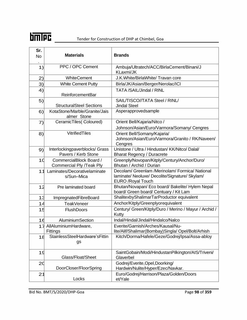
Tender for Construction of DHP at Chimbel, Goa
Bid No. BMT/S/2020/DHP-Goa Page 98 of 359
Sr.
No.
Materials
Brands
1) PPC / OPC Cement Ambuja/Ultratech/ACC/BirlaCement/Binani/JKLaxmi/JK
2) WhiteCement J.K.White/BirlaWhite/ Travan core
3) White Cement Putty Birla/JK/Asian/Berger/Nerolac/ICI
4) ReinforcementBar
TATA /SAIL/Jindal / RINL
5) StructuralSteel Sections
SAIL/TISCO//TATA Steel / RINL/ Jindal Steel
6) KotaStone/Marble/Granite/Jaisalmer Stone
Asperapprovedsample
7) CeramicTiles( Coloured) Orient Bell/Kajaria/Nitco /
Johnson/Asian/Euro/Varmora/Somany/ Cengres
8) VitrifiedTiles Orient Bell/Somany/Kajaria/ Johnson/Asian/Euro/Varmora/Granito / RK/Naveen/ Cengres
9) Interlockingpaverblocks/ Grass Pavers / Kerb Stone
Unistone / Ultra / Hindustan/ KK/Nitco/ Dalal/ Bharat Regency / Duracrete
10) CommercialBlock Board / Commercial Ply /Teak Ply
Greenply/Novopan/Kitply/Century/Anchor/Duro/ Bhutan / Archid / Durian
11) Laminates/Decorativelaminates/Sun–Mica
Decolam/ Greenlam /Merinolam/ Formica/ National laminate/ Neoluxe/ Decolite/Signature/ Skylam/ EURO /Royal Touch
12) Pre laminated board Bhutan/Novapan/ Eco board/ Bakelite/ Hylem Nepal board/ Green board/ Centuary / Kit Lam
13) ImpregnatedFibreBoard ShalitexbyShalimarTarProductor equivalent
14) TeakVeneer
Anchor/Kitply/Greenplyorequivalent
15) FlushDoors
Century/ Green/Kitply/Duro / Merino / Mayur / Archid / Kutty
16) AluminiumSection Indal/Hindal/Jindal/Hindalco/Nalco
17) AllAluminiumHardware, Fittings
Everite/Garnish/Arches/Kausal/Nu-lite/Alif/Shalimar(Bombay)Singla/ Opel/Bolt/Arhish
18) StainlessSteelHardware’sFittings
Kitch/Dorma/Hafele/Geze/Godrej/Ipsa/Assa-abloy
19) Glass/Float/Sheet
SaintGobain/Modi/HindustanPilkington/AIS/Triveni/Glaverbel
20) DoorCloser/FloorSpring
Godrej/Everite,Opel,Doorking/ Hardwin/Nulite/Hyper/Ezec/Navkar.
21) Locks
Euro/Godrej/Harrison/Plaza/Golden/Doorset/Yale

Tender for Construction of DHP at Chimbel, Goa
Bid No. BMT/S/2020/DHP-Goa Page 99 of 359
22) PolysulphideSealantForExpansionJointsAllWindows
ChokesyChemical/StructureProofingCoPidilite/GESilicon/Tuffsealor equivalent
23) SyntheticEnamelPaints/Primer/OilboundDistemper
Nerolac/Berger/AsianPaint/ICIDulux/Shalimar.
24) WaterProofAcrylicPaints /WeatherproofAcrylicPaints
Nerolac/Berger/ AsianPaint/ICIDulux/Shalimar
25) WaterbasedDistemper(Washable)
Nerolac/Berger/ AsianPaint/ICIDulux/Shalimar
26) Polyurethane Paint MRF/Alchemicaorequivalent
27) WaterProofingCompound 'CICO'/Fosroc/GESillicon /Pidilite/MC-Bauchmie/Sika/Farmate/Tape crete /Accoproof/ Impremo /Reoplast
28) WeatherSealent/Silicon Sealant
/Polyisobutylenesealant
Fosroc/Pidilite/MC-Bauchmie /Wecker789/ Dow corning789 or equivalent
29) Hardeners 'Ironite'/'Ferrok'/'Hardonate' or equivalent.
30) WireMesh SterlingEnterprises/Trimurti/Welded Mesh or equivalent
31) Anti-TermiteTreatment ThyodinbyHoechest/LyntricbyBayerIndia/DurmetbyCynamidIndia/NocilPyramid or equivalent
32) PrecoatedSheets TataBluescope/Multicolorsteels/Interarch/Kirby/Tigersteelorequivalent
33) PolyesterFibre Recron3S/Formate or equivalent
34) WeldingRod Advani/Philips/Sunarc/Eshabor equivalent
35) ConstructionChemicals Fosroc/MC-Bauchmie/Sika/Pidilite/Formate/SuperplastSNF40/BASF
36) AACBlock Builtech / Magicrete Building Solution / Aerocon / Indo Bhutan Construction Solution
37) Chemicalmortar/AACblockjointer Ultratech / Ferrouscrete / Bal Endura
38) Polymer Modified CementitiousGrout
Bal Endura / Webber / MykLaticrete
39) Epoxy Mortar Fosroc / Sika / Cico / Laticrete
40) UPVCWindows/Doors
/Ventilators
Encraft / Aluplast / Rehau / Duroplast/Fenesta/ Polywood
41) Wooden /Metal / Glaze- Fire Rated DoorShutters
Navair / Sukri / Promat / Kutty/Bhawani / Pacific
42) Hinges&Brassware Shalimar/ Indo-Brass / AmarbhoyDossaji / Earl Bihari / Magnum/Kich
43) Fire-Rated Glass(Two Hour FireRating) Transparent Clear
Glass
Glaverbel / Saint Gobbin / Pyroguard / Shott
44) All HardwareAndFittings ForAllTypesOf Glazing
Dorma / Hafele / Gezei / Kich / Godrej / Assa-Abloy

Tender for Construction of DHP at Chimbel, Goa
Bid No. BMT/S/2020/DHP-Goa Page 100 of 359
/Doors / WindowsEtc.
45) Adhesives Anchor / Dunlop / Pidilite- Fevicol
46) SSMesh GKD / WMW
47) HardwareAccessoriesForFireDoors /Panic Bar / PanicTrim/ Door Closer /Hinges / MortiseLock
IndersollRond / Dorma/ Geze / Hafele / Assa-Abloy / Kich
48) Tile Adhesive /Epoxy Grouts Ferrous Crete / BalllEndura / Pidilite / Lati Crete
49) Bitumen Indian Oil, Hindustan Petroleum
50) Dash Fastners Hilti/ Fischer/ Bosch
51) S.S. Staircase Railing Jindal Stainless Steel Ltd./ ICICH Industries/Essal
52) Nuts, Bolts And Screws, Steel Kundan/Priya/Atul
53) EPDM Gasket Hanu/Anand/Lescuyer
54) Fire Glass For Vision Pannels Saint Gobain/Ashai India
55) Fire Door Godrej/Shakti/Navair
56) Rolling Shutter
Rama Rolling Shutter/JyotiRollingShutter/Anand Industries
57) POP (Plaster Of Paris) J K Laxmi/SriramNirman/ Trimurti/ ISIMarkOnly
58) PVC Doors Fabricated From Rajshree/Finolex Plastics / Sintex
59) Factory Made Section Window ISI Mark Product Only
60) Powder Coated Aluminium Door Fittings
ISI Mark Only
61) Gypsum Board Gyproc by Saint Gobain / USG Boral / Knoff
62) Fibre Cement Board Everest / Visaka/ Swastik
63) Cement Bonded Particle Board NCL Industries or equivalent ISI mark product only
64) Project Management Software Nadhi Information Technologies Pvt. Ltd/ Coaspect Solutions Pvt. Ltd/ Cognisite/ Quickspec/ Superwise Solutions Pvt. Ltd/ Builsys
LIST OF MATERIALS OF APPROVED BRAND / MANUFACTURER (ONLY FIRST
QUALITY TO BE USED (WATER SUPPLY & SANITARY WORKS)
Sr.
No. Materials
Brands
1. Vitreous China Ware Hindware / Parryware / Cera / Johnson / Hindustan/ Neycer/
Varmora
2. RCC Pipes Pragati / Lakshmi / Sood&Sood / Jain & Co /Diwan

Tender for Construction of DHP at Chimbel, Goa
Bid No. BMT/S/2020/DHP-Goa Page 101 of 359
3. UPVC / CPVC Pipes &
Fittings
Supreme / Prince / Astral / Finolex / Surya Roshni / Ashirwad/
Prakash/Kisan
4. Stainless Steel Sinks Neelkanth / Nirali / Cera/Jayna/ Diamond / Cobra
5. Spun Cast Iron Pipes & Fittings (IS:3989)
Jaiswal Neco/ RIF / SKF / BIC
6. Stoneware Pipes and Gully
Traps
Perfect / Burn / Anand / Parry/ Hind
7. Gunmetal Valves (Full Way Valve) Class-I
Zoloto / Castle/ Kartar/Leader /Sant/ Prima
8. CI Double Flanged Sluice Valve Kirloskar / IVC / Sondhi / Kejriwal/Burn
9. CI Manhole Frame & Covers and CI Grating
Neco / RIF / SKF / BIC
10. Sanitary CP Fittings &
Accessories
Marc / Parryware / Kingston/Gem/Parko/ Hindustan /Cera
11. Floor Traps (Jali) Jayna / Chilly / Nirali
12. PVC Water Tank Sintex / Polycon / SPL/Reno/ Sheetal
13. Flushing Cistern CERA/Hindware/Johnson/Hindustan/Perryware
14. E.W.C.Seats(Cover) CERA/Hindware/Johnson/Hindustan/Perryware/EID/Neycer/Varmora.
15. Mirrors ModiFloatglass/Asahi/SaintGobin/ AtulGlasswork
16. FibrereinforcedR.C.C.Manholecover KK / Nitco/ Dalal
17. C.I.Manholecoverwithframe ISIapprovedmakeorequivalent
18. P.V.C.Pipes&Fittings Astral/Supreme/Prince/Finolex/AshirvadPipes/Jain/Kisan
19. BallCock Zoloto/ Prima/ IBT/ RCO/Sant
20. UPVCPipes(SolventWeldedJoints) Astral/Supreme/Prince/Finolex/AshirvadPipes/ Jain/Kisan/KSR/Precision/AjayDustron
21. PTMT Prayag/ Polytuf or equivalent
22. Ductile Iron Pipe (Water pipe) Electro Steel/ Kesso/ Kdupl./ Electron Spun
23. PVC Flushing Cistern Hindware/ Steelbird / Jindal/ Seabird ISI mark only
LIST OF MATERIALS OF APPROVED BRAND / MANUFACTURER
(ONLY FIRST QUALITY TO BE USED (ELECTRICAL WORKS)
Sr. No. Materials Brands
1. FRLS PVC Insulated Copper
Wire /Power Cable / Xlpe
Cable / Telephone Cable
L&T / Havel’s / Polycab / Finolex
/ Sky Tone

Tender for Construction of DHP at Chimbel, Goa
Bid No. BMT/S/2020/DHP-Goa Page 102 of 359
2. Co-Axial TV Cable L&T / Havel’s /Polycab / Finolex / Sky Tone.
3. Steel Conduit RM Con / AKG/ BEC ISI Marked.
4. PVC Conduit AKG / Polycab / Prince
5. L. T. Panel / Meter Board Adlecmundka / Associated Switchgears And
Project Ltd. / SudhirGenset Ltd. / Control And Switchgears Pvt. Ltd / Kepl/Tricolite
6. MCB/MCB DB, Prewired MCB
Db And Sheet Steel Metal
Enclosed Industrial Socket,
Plug Top And Isolators
Legrand / Siemens / L&T / Abb / Schneider
7. Modular Type Switch/Socket, Telephone Socket, Cable Tv
Antenna Socket, Electronic
Fan Regulator And Gi Boxes
Anchor / Vinay/Crabtree /Legrand (Mylinc / Havel’s (Piccadilly) / Honeywell (Midas) /North West (Nova)
8. LED Fitting Philips / Crompton / Wipro / Ge / Zumpobel /
Trilux
9. Ceiling Fan / Exhaust Fan Crompton Greaves / Almonard / Havells /
Usha.
10. Octagonal Steel Pole Bajaj/ Twinkle / Valmart
11. Air Circuit Breaker / MCCBb. L&T-U Power / Siemens-3wl / Abb- Emax /
Schneider-Masterpact- Nw
12. Alternator Stamford / Leroy Somer / Caterpillar /
Koel Green
13. Copper Conductor Control
Cable
Bonton / Lapp Cable / Havells / Rr Kabel /
L&T / Rajnigandha
14. Communication Cable /
Signal Cable
Lapp Cable / Fusion Polymer / Beldon
15. Motor/ Pumps ABB/ Siemens/ Kirloskar
Crompton Greaves
16. Starter L&T/ Siemens / Crompton/ Ge Abb / Bch
17. Armouredcables Tropodure/Incab/torrent/ Finolex/ Unistar/ Avocab/Havells/Gloster
18. Motorstarter/Panel L&T/Siemens/Havells/Galco/Ellico/ BCH/C&S
19. Fire Extinguisher Safex/ Minimex/ Superex/ Ceasefire
20. First Aid Hose Real, Nozzles, valves, Hose pipe and other
fittings
ISI mark only
Notes: a) The contractor shall produce samples of the materials for approval of the authorized
representative of BMTPC. The materials of the makes out of the above as approved by the authorized representative of BMTPC shall be used on the work.
b) In respect of materials for which approved makes are not specified above, ISI make of materials to be used by taking approval from authorized representative of BMTPC. If ISI make materials are not available, materials to be approved by Competent Authority.

Tender for Construction of DHP at Chimbel, Goa
Bid No. BMT/S/2020/DHP-Goa Page 103 of 359
c) For all the material of approved brands necessary testing as per IS standards shall be done by the agency and no extra payment shall be paid for that.

Tender for Construction of DHP at Chimbel, Goa
Bid No. BMT/S/2020/DHP-Goa Page 104 of 359
Appendix-II GUARANTEE TO BE EXECUTED BY AGENCY FOR REMOVAL OF DEFECTS AFTER COMPLETION IN RESPECT OF WATER PROOFING WORKS The agreement made this……..………………….day of year two thousand and …….……………between ……………..………………………..…………………………. (Hereinafter called the Guarantor of the one part) and the BMTPC (Hereinafter called the Implementing Agency of the other part). WHEREAS THIS agreement is supplementary to a contract (Hereinafter called the contract) dated ……………… and made between the GUARANTOR OF THE ONE PART AND the BMTPC of the other part, whereby the agency inter-alia, undertook to render the building and structures in the said contract recited completely water and leak proof. AND WHEREAS THE GUARANTOR agreed to give guarantee to the affect that the said work will remain water and leak proof for five years from the date of giving of water proofing treatment. NOW THE GUARANTOR hereby guarantee that water proofing treatment given by him will render the structures completely leak proof and the minimum life of such water proofing treatment shall be ten years to be reckoned from the date after the maintenance period prescribed in the contract. Provided that the guarantor will not be responsible for leakage caused by earthquake or structural defects or misuse or alteration and for such purpose.
a) Misuse of roof shall mean any operation which will damage proofing treatment, like chopping of firewood and things of the same nature which might cause damage to the proof.
b) Alteration shall mean construction of an additional storey or a part of the roof or construction adjoining to existing roof whereby proofing treatment is removed in parts.
c) The decision of the Competent Authority with regard to nature and cause of defects shall be final.
During this period of guarantee, the guarantor shall make good all defects and in case of any defect being found render the building water proof to the satisfaction of the Competent Authority at his cost and shall commence the work for such rectification within seven days from the date of issue of the notice from Competent Authority calling upon him to rectify the defects failing which the work shall be got done by the Department by some other agency at the Guarantors risk and cost. The decision of the Competent Authority as to the cost payable by the Guarantor shall be final and binding. That if guarantor fails to execute the water proofing or commits breach there under; then the guarantor will indemnify the Principal and his successors against all loss, damage, cost any default on the part of the GUARANTOR in performance and observance of this supplementary agreement. As to the amount of loss and/ or damage and/or cost incurred by the BMTPC,
Tender for Construction of DHP at Chimbel, Goa
Bid No. BMT/S/2020/DHP-Goa Page 105 of 359
the decision of the Competent Authority will be final and binding on the parties. IN WITNESS WHEREOF these presents have been executed by the selected agency
……………………………….. and …………………By…………….. For and on behalf of the
BMTPC on the day, month and year first above written.
SIGNED, sealed and delivered by selected agency in the presence of : 1. ……………………… 2. ………………………… SIGNED FOR AND ON BEHALF OF BMTPC By …………………………………… in the presence of : 1. ………………… 2. …………………………………

Tender for Construction of DHP at Chimbel, Goa
Bid No. BMT/S/2020/DHP-Goa Page 106 of 359
6. SCHEDULE OF FINISHES &SPECIFICATIONS
1.0 Specifications for Dwelling Units and other provisions
The specification for construction of Dwelling Units and other provisions shall be as under:
Sl.No Item of Work Specification
1. FOUNDATION & PLINTH (AS PER DRAWING)
1.1 Excavation All type of excavation will be part of work including site clearance, dewatering from trenches etc. or clearing and cutting of shrubs / small trees etc.
1.2 Foundation & Plinth Pile foundation, Strip foundation, isolated column, spread foundation or raft foundation as per structural design, drawings and soil investigation report.
1.3 Concrete in Foundation for Columns / walls
No concreting less than M20 strength will be used for foundation work either for frame structure or raft foundation as per design. The type of mix, thickness and width shall depend on approved structural design. The base concrete will not be less than M7.5
1.4 Plinth Beam Plinth beam to be provided, Concrete will not be less than M20 strength
1.5 Anti-termite Anti- termite treatment will be as per CPWD specification
1.6 Damp Proof Course over Plinth Beam
Damp-proof course should be 40mm thick with cement concrete 1:2:4 (1 cement : 2 coarse sand (zone-III): 4 graded stone aggregate 12.5mm nominal size), if required.
1.7(a) Plinth Filling : a) Sand filling : / Concrete under floor :
Filling with sand in trenches or embankment in layers (each layer should not exceed 15 cm), including watering and ramming and 100mm layer of CC 1:4:8 (1 cement: 4 coarse sand: 8 stone aggregate) 40 mm nominal size under floor.
1.7(b) Internal Filling Internal filling will be excavated soil or earth filling with soil brought from outside.
1.8 Brick work in foundation & plinth :
Brick of class designated 100A will be used. Brick Masonry provided with cement mortar shall be with coarse sand minimum 1:6 (1 cement: 6 course sand) or richer mixes subject to the provisions of the approved structural drawings.
2 SUPER STRUCTURE WORK
2.1 Walling (As per Drawing)
As per specification of proposed Technology
2.2 Slab and Staircase including projections /lintel/sunshades(As per Drawing)
Reinforced Cement Concrete slab with Reinforcement as per the structural design and drawing (As per proposed Technology). Grade of Steel and Concrete Shall be Fe 500 and Minimum M20 strength respectively.
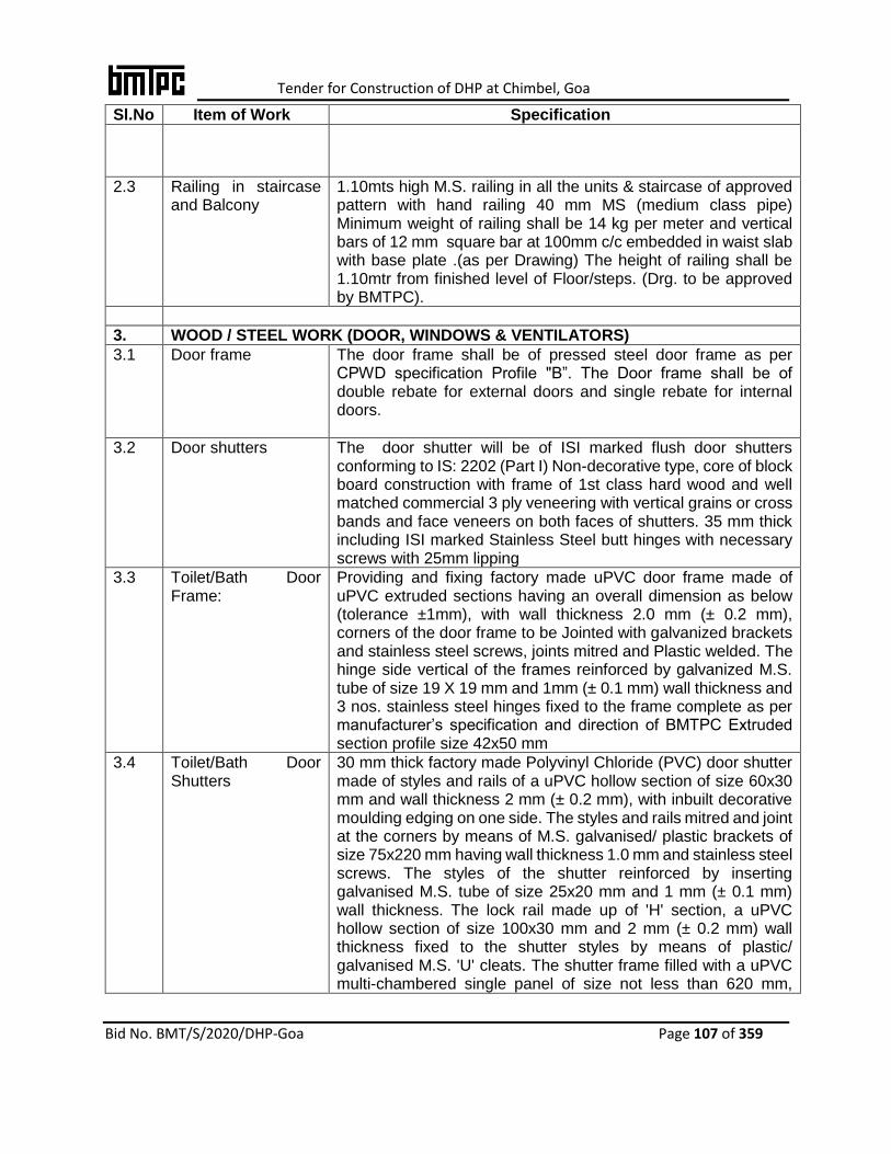
Tender for Construction of DHP at Chimbel, Goa
Bid No. BMT/S/2020/DHP-Goa Page 107 of 359
Sl.No Item of Work Specification
2.3 Railing in staircase and Balcony
1.10mts high M.S. railing in all the units & staircase of approved pattern with hand railing 40 mm MS (medium class pipe) Minimum weight of railing shall be 14 kg per meter and vertical bars of 12 mm square bar at 100mm c/c embedded in waist slab with base plate .(as per Drawing) The height of railing shall be 1.10mtr from finished level of Floor/steps. (Drg. to be approved by BMTPC).
3. WOOD / STEEL WORK (DOOR, WINDOWS & VENTILATORS)
3.1 Door frame The door frame shall be of pressed steel door frame as per CPWD specification Profile "B”. The Door frame shall be of double rebate for external doors and single rebate for internal doors.
3.2 Door shutters The door shutter will be of ISI marked flush door shutters conforming to IS: 2202 (Part I) Non-decorative type, core of block board construction with frame of 1st class hard wood and well matched commercial 3 ply veneering with vertical grains or cross bands and face veneers on both faces of shutters. 35 mm thick including ISI marked Stainless Steel butt hinges with necessary screws with 25mm lipping
3.3 Toilet/Bath Door Frame:
Providing and fixing factory made uPVC door frame made of uPVC extruded sections having an overall dimension as below (tolerance ±1mm), with wall thickness 2.0 mm (± 0.2 mm), corners of the door frame to be Jointed with galvanized brackets and stainless steel screws, joints mitred and Plastic welded. The hinge side vertical of the frames reinforced by galvanized M.S. tube of size 19 X 19 mm and 1mm (± 0.1 mm) wall thickness and 3 nos. stainless steel hinges fixed to the frame complete as per manufacturer’s specification and direction of BMTPC Extruded section profile size 42x50 mm
3.4 Toilet/Bath Door Shutters
30 mm thick factory made Polyvinyl Chloride (PVC) door shutter made of styles and rails of a uPVC hollow section of size 60x30 mm and wall thickness 2 mm (± 0.2 mm), with inbuilt decorative moulding edging on one side. The styles and rails mitred and joint at the corners by means of M.S. galvanised/ plastic brackets of size 75x220 mm having wall thickness 1.0 mm and stainless steel screws. The styles of the shutter reinforced by inserting galvanised M.S. tube of size 25x20 mm and 1 mm (± 0.1 mm) wall thickness. The lock rail made up of 'H' section, a uPVC hollow section of size 100x30 mm and 2 mm (± 0.2 mm) wall thickness fixed to the shutter styles by means of plastic/ galvanised M.S. 'U' cleats. The shutter frame filled with a uPVC multi-chambered single panel of size not less than 620 mm,
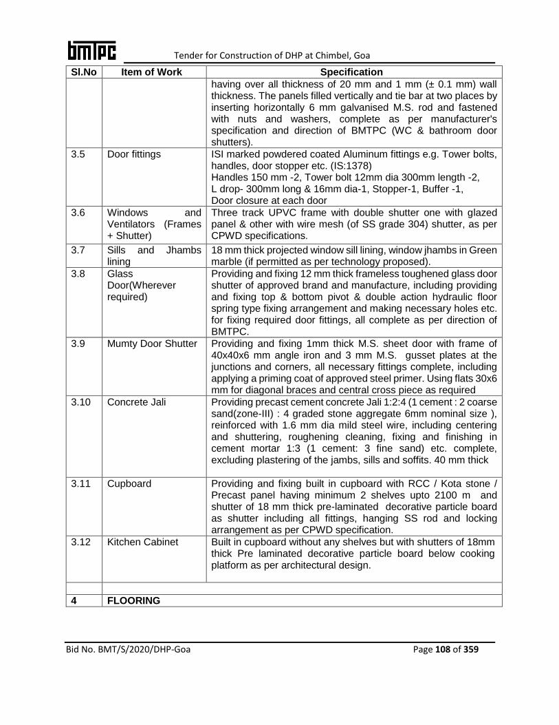
Tender for Construction of DHP at Chimbel, Goa
Bid No. BMT/S/2020/DHP-Goa Page 108 of 359
Sl.No Item of Work Specification
having over all thickness of 20 mm and 1 mm (± 0.1 mm) wall thickness. The panels filled vertically and tie bar at two places by inserting horizontally 6 mm galvanised M.S. rod and fastened with nuts and washers, complete as per manufacturer's specification and direction of BMTPC (WC & bathroom door shutters).
3.5 Door fittings ISI marked powdered coated Aluminum fittings e.g. Tower bolts, handles, door stopper etc. (IS:1378) Handles 150 mm -2, Tower bolt 12mm dia 300mm length -2, L drop- 300mm long & 16mm dia-1, Stopper-1, Buffer -1, Door closure at each door
3.6 Windows and Ventilators (Frames + Shutter)
Three track UPVC frame with double shutter one with glazed panel & other with wire mesh (of SS grade 304) shutter, as per CPWD specifications.
3.7 Sills and Jhambs lining
18 mm thick projected window sill lining, window jhambs in Green marble (if permitted as per technology proposed).
3.8 Glass Door(Wherever required)
Providing and fixing 12 mm thick frameless toughened glass door shutter of approved brand and manufacture, including providing and fixing top & bottom pivot & double action hydraulic floor spring type fixing arrangement and making necessary holes etc. for fixing required door fittings, all complete as per direction of BMTPC.
3.9 Mumty Door Shutter Providing and fixing 1mm thick M.S. sheet door with frame of 40x40x6 mm angle iron and 3 mm M.S. gusset plates at the junctions and corners, all necessary fittings complete, including applying a priming coat of approved steel primer. Using flats 30x6 mm for diagonal braces and central cross piece as required
3.10 Concrete Jali Providing precast cement concrete Jali 1:2:4 (1 cement : 2 coarse sand(zone-III) : 4 graded stone aggregate 6mm nominal size ), reinforced with 1.6 mm dia mild steel wire, including centering and shuttering, roughening cleaning, fixing and finishing in cement mortar 1:3 (1 cement: 3 fine sand) etc. complete, excluding plastering of the jambs, sills and soffits. 40 mm thick
3.11 Cupboard Providing and fixing built in cupboard with RCC / Kota stone / Precast panel having minimum 2 shelves upto 2100 m and shutter of 18 mm thick pre-laminated decorative particle board as shutter including all fittings, hanging SS rod and locking arrangement as per CPWD specification.
3.12 Kitchen Cabinet Built in cupboard without any shelves but with shutters of 18mm thick Pre laminated decorative particle board below cooking platform as per architectural design.
4 FLOORING
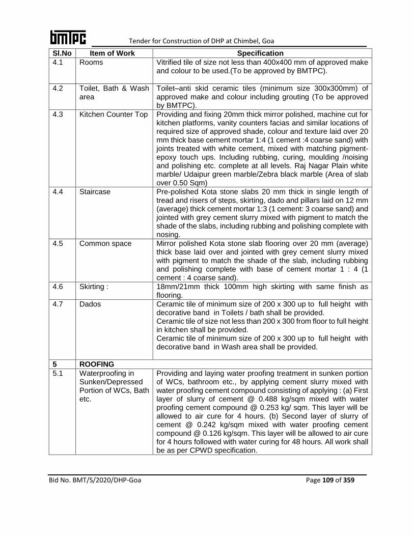
Tender for Construction of DHP at Chimbel, Goa
Bid No. BMT/S/2020/DHP-Goa Page 109 of 359
Sl.No Item of Work Specification
4.1 Rooms
Vitrified tile of size not less than 400x400 mm of approved make and colour to be used.(To be approved by BMTPC).
4.2 Toilet, Bath & Wash area
Toilet–anti skid ceramic tiles (minimum size 300x300mm) of approved make and colour including grouting (To be approved by BMTPC).
4.3 Kitchen Counter Top Providing and fixing 20mm thick mirror polished, machine cut for kitchen platforms, vanity counters facias and similar locations of required size of approved shade, colour and texture laid over 20 mm thick base cement mortar 1:4 (1 cement :4 coarse sand) with joints treated with white cement, mixed with matching pigment-epoxy touch ups. Including rubbing, curing, moulding /noising and polishing etc. complete at all levels. Raj Nagar Plain white marble/ Udaipur green marble/Zebra black marble (Area of slab over 0.50 Sqm)
4.4 Staircase Pre-polished Kota stone slabs 20 mm thick in single length of tread and risers of steps, skirting, dado and pillars laid on 12 mm (average) thick cement mortar 1:3 (1 cement: 3 coarse sand) and jointed with grey cement slurry mixed with pigment to match the shade of the slabs, including rubbing and polishing complete with nosing.
4.5 Common space Mirror polished Kota stone slab flooring over 20 mm (average) thick base laid over and jointed with grey cement slurry mixed with pigment to match the shade of the slab, including rubbing and polishing complete with base of cement mortar 1 : 4 (1 cement : 4 coarse sand).
4.6 Skirting : 18mm/21mm thick 100mm high skirting with same finish as flooring.
4.7 Dados Ceramic tile of minimum size of 200 x 300 up to full height with decorative band in Toilets / bath shall be provided. Ceramic tile of size not less than 200 x 300 from floor to full height in kitchen shall be provided. Ceramic tile of minimum size of 200 x 300 up to full height with decorative band in Wash area shall be provided.
5 ROOFING
5.1 Waterproofing in Sunken/Depressed Portion of WCs, Bath etc.
Providing and laying water proofing treatment in sunken portion of WCs, bathroom etc., by applying cement slurry mixed with water proofing cement compound consisting of applying : (a) First layer of slurry of cement @ 0.488 kg/sqm mixed with water proofing cement compound @ 0.253 kg/ sqm. This layer will be allowed to air cure for 4 hours. (b) Second layer of slurry of cement @ 0.242 kg/sqm mixed with water proofing cement compound @ 0.126 kg/sqm. This layer will be allowed to air cure for 4 hours followed with water curing for 48 hours. All work shall be as per CPWD specification.

Tender for Construction of DHP at Chimbel, Goa
Bid No. BMT/S/2020/DHP-Goa Page 110 of 359
Sl.No Item of Work Specification
5.2 Terrace Treatment : Providing and laying water proofing treatment on roofs of slabs by applying cement slurry mixed with water proofing cement compound consisting of applying: (A) After surface preparation, two coats of mixed slurry to be applied to the set concrete @1.5-2 kg/m² by a masonry brush, roller or appropriate power spray equipment. This will be allowed to air cure for 4 hours followed by water curing for 48 hours. The entire treatment will be taken upto 30 cm on parapet wall and tucked into groove in parapet all around. (B) After complete curing, laying protection screed concrete in the ratio 1:2:4 not more the 50 mm in thickness. Flooded the entire slab for minimum curing period of 48 hours or Koba treatment as per CPWD specifications and technology requirement.
5.2 Gola in C.C 1:2:4 Providing gola 75x75 mm in cement concrete 1:2:4 (1 cement: 2 coarse sand:4 stone aggregate 10mm and down gauge) including finishing with cement mortar 1:3(1 cement: 3 coarse sand)as per standard design In 75x75 mm deep chase
5.3 Rain Water Pipes Providing and fixing on wall face unplasticised Rigid PVC rain water pipes conforming to IS : 13592 Type A, including jointing with seal ring conforming to IS : 5382, leaving 10 mm gap for thermal expansion, including all required accessories and making of khurra 45 x 45cm. as per CPWD norms. It shall be responsibility of contractor to make essential arrangement for disposal of rain water by providing proper sloping of roof slab and by providing appropriate uPVC pipes and fittings all complete. Duct portion (if any) up to plinth level shall be constructed as collecting chamber and uPVC pipe/ uPVC shoe at bottom shall be fixed for disposal of rain water.
5.4 Parapet with coping Parapet in proposed technology having height of 1.10 mt with 25mm thick CC coping in M20 grade concrete including neat cement plaster in cement mortar 1:6.
6 FINISHING
6.1 Finishing Internal/ External walls (Wherever required)
12/15/20 mm cement plaster in 1:6 (1 cement : 6 fine sand)finished or as per technology provider’s specification including admixture if required .
6.2 Finishing bottom of RCC slab
6 mm cement plaster1:3(1 cement : 3 fine sand) for Finishing bottom RCC Slab, beams, plaster to ceiling etc.
6.3 Painting :Internal finish on walls/Ceilings
Distempering with Oil Bound distemper over 2 mm thick POP on walls
6.4 Painting External finish on walls
Weather Proof Acrylic Emulsion paint on base of 2 mm thick external wall putty.
6.5 Primer : As per CPWD Specification for walls, wood work and steel work.( Zinc chromate primer)
6.6 Painting on wood work & steel work:
Painting with synthetic enamel paint, of approved brand and manufacture, including applying additional coats wherever required to achieve even shade and colour. Two coats or more
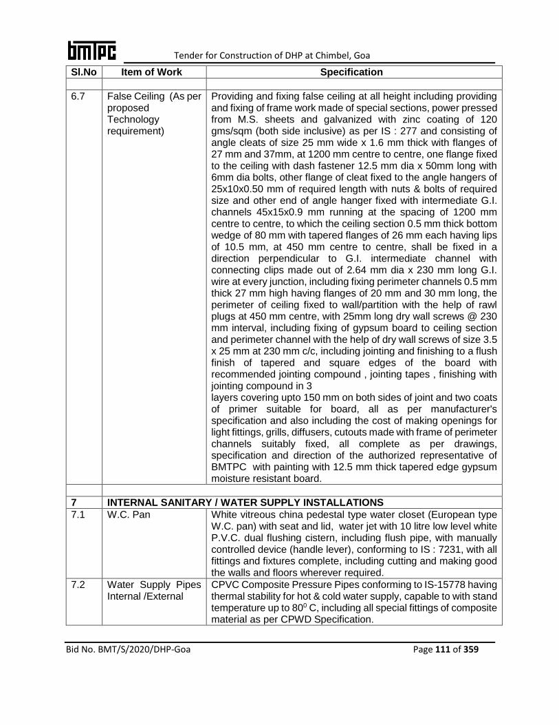
Tender for Construction of DHP at Chimbel, Goa
Bid No. BMT/S/2020/DHP-Goa Page 111 of 359
Sl.No Item of Work Specification
6.7 False Ceiling (As per proposed Technology requirement)
Providing and fixing false ceiling at all height including providing and fixing of frame work made of special sections, power pressed from M.S. sheets and galvanized with zinc coating of 120 gms/sqm (both side inclusive) as per IS : 277 and consisting of angle cleats of size 25 mm wide x 1.6 mm thick with flanges of 27 mm and 37mm, at 1200 mm centre to centre, one flange fixed to the ceiling with dash fastener 12.5 mm dia x 50mm long with 6mm dia bolts, other flange of cleat fixed to the angle hangers of 25x10x0.50 mm of required length with nuts & bolts of required size and other end of angle hanger fixed with intermediate G.I. channels 45x15x0.9 mm running at the spacing of 1200 mm centre to centre, to which the ceiling section 0.5 mm thick bottom wedge of 80 mm with tapered flanges of 26 mm each having lips of 10.5 mm, at 450 mm centre to centre, shall be fixed in a direction perpendicular to G.I. intermediate channel with connecting clips made out of 2.64 mm dia x 230 mm long G.I. wire at every junction, including fixing perimeter channels 0.5 mm thick 27 mm high having flanges of 20 mm and 30 mm long, the perimeter of ceiling fixed to wall/partition with the help of rawl plugs at 450 mm centre, with 25mm long dry wall screws @ 230 mm interval, including fixing of gypsum board to ceiling section and perimeter channel with the help of dry wall screws of size 3.5 x 25 mm at 230 mm c/c, including jointing and finishing to a flush finish of tapered and square edges of the board with recommended jointing compound , jointing tapes , finishing with jointing compound in 3 layers covering upto 150 mm on both sides of joint and two coats of primer suitable for board, all as per manufacturer's specification and also including the cost of making openings for light fittings, grills, diffusers, cutouts made with frame of perimeter channels suitably fixed, all complete as per drawings, specification and direction of the authorized representative of BMTPC with painting with 12.5 mm thick tapered edge gypsum moisture resistant board.
7 INTERNAL SANITARY / WATER SUPPLY INSTALLATIONS
7.1 W.C. Pan White vitreous china pedestal type water closet (European type W.C. pan) with seat and lid, water jet with 10 litre low level white P.V.C. dual flushing cistern, including flush pipe, with manually controlled device (handle lever), conforming to IS : 7231, with all fittings and fixtures complete, including cutting and making good the walls and floors wherever required.
7.2 Water Supply Pipes Internal /External
CPVC Composite Pressure Pipes conforming to IS-15778 having thermal stability for hot & cold water supply, capable to with stand temperature up to 800 C, including all special fittings of composite material as per CPWD Specification.
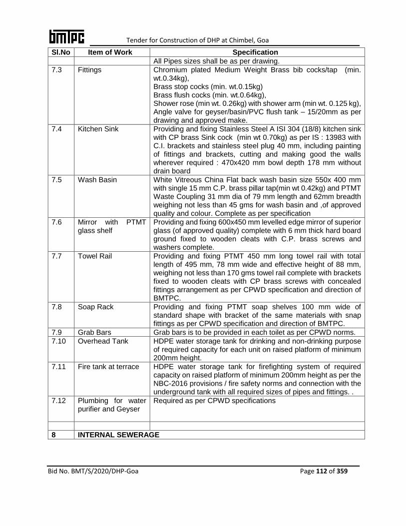
Tender for Construction of DHP at Chimbel, Goa
Bid No. BMT/S/2020/DHP-Goa Page 112 of 359
Sl.No Item of Work Specification
All Pipes sizes shall be as per drawing.
7.3 Fittings Chromium plated Medium Weight Brass bib cocks/tap (min. wt.0.34kg), Brass stop cocks (min. wt.0.15kg) Brass flush cocks (min. wt.0.64kg), Shower rose (min wt. 0.26kg) with shower arm (min wt. 0.125 kg), Angle valve for geyser/basin/PVC flush tank – 15/20mm as per drawing and approved make.
7.4 Kitchen Sink Providing and fixing Stainless Steel A ISI 304 (18/8) kitchen sink with CP brass Sink cock (min wt 0.70kg) as per IS : 13983 with C.I. brackets and stainless steel plug 40 mm, including painting of fittings and brackets, cutting and making good the walls wherever required : 470x420 mm bowl depth 178 mm without drain board
7.5 Wash Basin White Vitreous China Flat back wash basin size 550x 400 mm with single 15 mm C.P. brass pillar tap(min wt 0.42kg) and PTMT Waste Coupling 31 mm dia of 79 mm length and 62mm breadth weighing not less than 45 gms for wash basin and ,of approved quality and colour. Complete as per specification
7.6 Mirror with PTMT glass shelf
Providing and fixing 600x450 mm levelled edge mirror of superior glass (of approved quality) complete with 6 mm thick hard board ground fixed to wooden cleats with C.P. brass screws and washers complete.
7.7 Towel Rail Providing and fixing PTMT 450 mm long towel rail with total length of 495 mm, 78 mm wide and effective height of 88 mm, weighing not less than 170 gms towel rail complete with brackets fixed to wooden cleats with CP brass screws with concealed fittings arrangement as per CPWD specification and direction of BMTPC.
7.8 Soap Rack Providing and fixing PTMT soap shelves 100 mm wide of standard shape with bracket of the same materials with snap fittings as per CPWD specification and direction of BMTPC.
7.9 Grab Bars Grab bars is to be provided in each toilet as per CPWD norms.
7.10 Overhead Tank HDPE water storage tank for drinking and non-drinking purpose of required capacity for each unit on raised platform of minimum 200mm height.
7.11 Fire tank at terrace HDPE water storage tank for firefighting system of required capacity on raised platform of minimum 200mm height as per the NBC-2016 provisions / fire safety norms and connection with the underground tank with all required sizes of pipes and fittings. .
7.12 Plumbing for water purifier and Geyser
Required as per CPWD specifications
8 INTERNAL SEWERAGE

Tender for Construction of DHP at Chimbel, Goa
Bid No. BMT/S/2020/DHP-Goa Page 113 of 359
Sl.No Item of Work Specification
8.1 Pipes Providing and fixing on wall face unplasticised Rigid PVC soild and waste pipes conforming to IS : 13592 Type B, including jointing with seal ring conforming to IS : 5382, leaving 10 mm gap for thermal expansion, including all required accessories Sizes of all pipes shall be as per drawings.
8.2 Manholes Manholes. with brick of class designation 75 of required size as per drawing in cement mortar 1:4 (1 cement: 4 coarse sand) with foundation concrete 1:3:6 (1 cement: 3 coarse sand: 6 graded stone aggregate 20 mm nominal size) with stone aggregate inside cement plaster 1:4 (1 cement: 4 coarse sand) with floating coat of neat cement, outside (Refer Drawing) cement plaster 1:4 (1 cement: 4 coarse sand) with precast RCC cover heavy duty cover In sub-soil or adverse soil conditions, manholes & encasing pipes shall be as per approved credible structural design to avoid sinking and settlement of lines/manholes. All the manholes inside the building to be lined with sand stone lining from outside up to bottom level.
8.3 Gully Trap Providing and fixing square-mouth S.W. gully trap of required size as per drawing having class SP-1 complete with C.I. grating brick masonry chamber with water tight C.I. cover with frame of 300 x300 mm size (inside) the weight of cover to be not less than 4.50 kg and frame to be not less than 2.70 kg as per standard design: 100 x 100 mm size P Type With common burnt clay F.P.S. (non modular) bricks of class designation 7.5.
8.4 Floor Trap Providing 76.2mm (3”) NAHANY TRAP of PVC with SS 304 Jali (wt 50 gram) for Kitchen and Toilets.
9 NUMBERING OF HOUSES ETC.
9.1 Numbering of rooms, Pad Locks for Units
The numbering of size 100mm in height shall be printed on glazed tiles above the entrance door and Pad lock shall be provided on entrance door of each room, as per instructions of authorized representative of BMTPC.
INTERNAL ELECTRIC INSTALLATION (IEI)
1. The work will be carried out in recessed PVC conduit wiring system in accordance of latest CPWD General Specifications for Electrical Works with amendments up to the date of opening of tenders and the governing specifications including makes for some of the important materials to be used in the work. In case of ambiguity between the two, the specifications shall prevail. All Pipes sizes shall be as per drawing.
2. FRLS PVC insulated Copper conductor wires will be used for points, circuit & sub-main wiring. (Sizes shall be as per drawing/requirement)
3. Contractor shall execute the work as per attached inventory after obtaining necessary approval of the layout for internal electrification of houses staircase from BMTPC. The staircase lighting shall be in group control system.
4. All internal electrification work will be carried out as per CPWD Specifications, NBC, IE Rules, IS Codes etc. as amended up to the date of tender. In case for any part of the work specification is not available in the aforesaid mentioned documents then part of the work

Tender for Construction of DHP at Chimbel, Goa
Bid No. BMT/S/2020/DHP-Goa Page 114 of 359
will be carried out in accordance with sound engineering practice and as per directions of BMTPC.
5. Cover plates at all junction and Points, Ceiling rose for fan point. Modular type plates, switches, sockets and stepped type fan regulators, bell push along with matching mounting boxes of same make shall be used. Points to be provided in each unit shall not be less than 23 Points.
6. Modular Switches &Fixtures to be provided LED Tubelight fittings including tubes, Ceiling fans in each room as per requirement, Provisions of Exhaust fan in kitchen & Toilet / bath Bracket light with normal fitting excluding lamp/bulb in each room, kitchen, toilet / bath Call Bell Point as per requirement, Cable TV Point - 1 in each room, Plug Point(5 amp.) as per requirement in each room, kitchen, toilets, Power Point(15 amp.6 pin) - as per requirement in each room, kitchen, toilets, AC point with MCB - 1 in each room, Geyser point Kitchen and Toilets, EDM/MCB (single phase) -1 for each Unit, Bracket light / ceiling light with lighting fixture in common area and stair case(Solar Light)
7. Suitable rain protection covers made of 16SWG galvanized MS sheet wherever required shall be provided.
8. Bus Bar, Meter Boards & Main Distribution Boards with MCBs as per specification of Local Govt. shall also be provided by the contractor.
FIREFIGHTING SYSTEM
1. Fire extinguishers of required capacity, type and number on each floor as per the provisions of NBC-2016/ Fire Safety Norms
2. Swinging type First Aid Hose Real with double door hose cabinet of required size having front glass and lockable facilities, hose pipe/s, fire man axe etc. complete in all respect as per the provisions of NBC-2016/ Fire Safety Norms.
3. MS pipe of suitable size and grade with all fittings, valves etc. complete in all respect as per the provisions of NBC-2016/ Fire Safety Norms.
4. Bucket stand with sand / fire bucket in required numbers as per the provisions of NBC-2016/ Fire Safety Norms.
5. Two way fire brigade connection with gun metal male instantaneous inlet coupling with cap and chain including MS pipe upto fire tank complete in all respect.
6. Electrical driven terrace pump of 450 LPM at 35 meter head mounted MS fabricated common base plate including electrical control panel complete all respect
Note:
1. Before installation of Panel system, the agency shall have to produce evidence of quality
of material at site if asked for. The testing of materials will be carried out at the cost of
selected agency of BMTPC.
2. Any Material or Component (it’s ratio thereof.) not defined or missing, may be adopted by
the Agency in consultation & approval of BMTPC.
3. The items of works / specifications described above are only indicative and not
exhaustive. In additions to the above the agency shall be responsible for executing all
the items required for completing the houses and other provisions in all respect to make
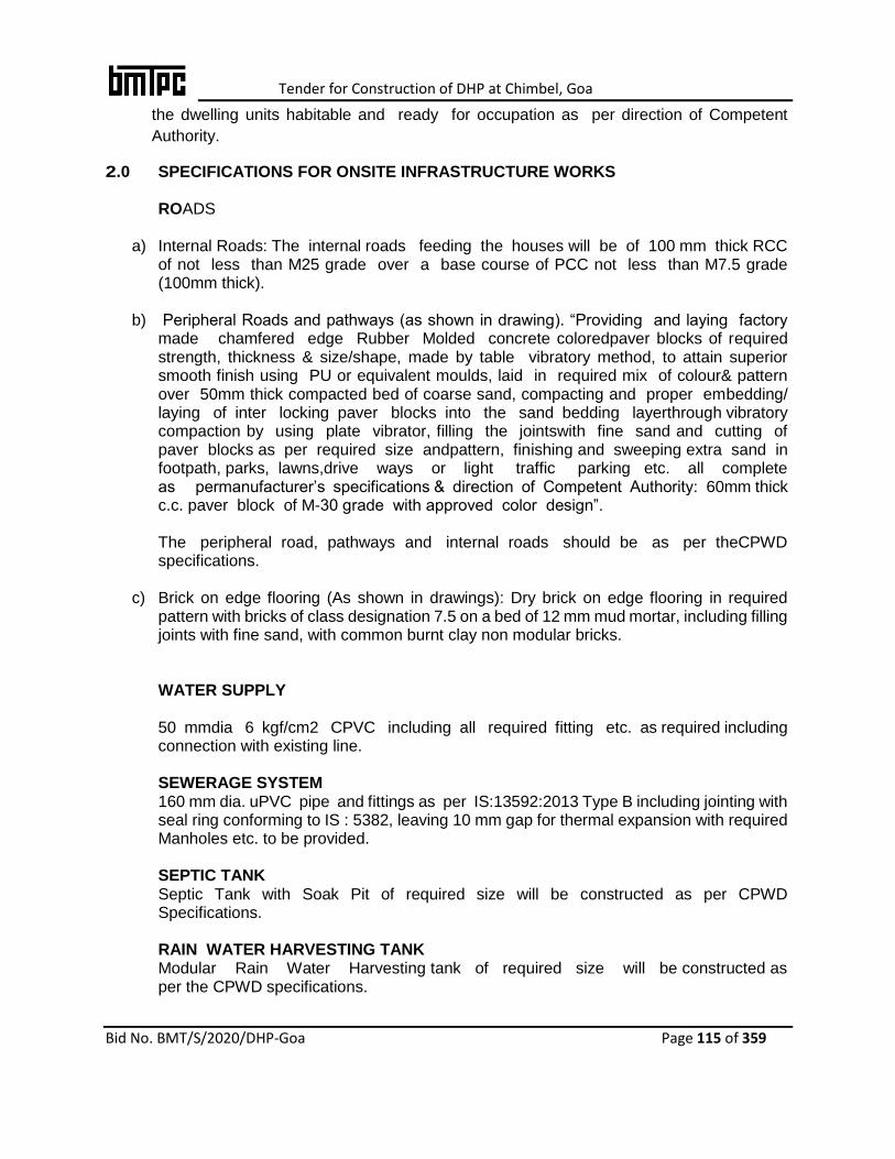
Tender for Construction of DHP at Chimbel, Goa
Bid No. BMT/S/2020/DHP-Goa Page 115 of 359
the dwelling units habitable and ready for occupation as per direction of Competent
Authority.
2.0 SPECIFICATIONS FOR ONSITE INFRASTRUCTURE WORKS
ROADS
a) Internal Roads: The internal roads feeding the houses will be of 100 mm thick RCC of not less than M25 grade over a base course of PCC not less than M7.5 grade (100mm thick).
b) Peripheral Roads and pathways (as shown in drawing). “Providing and laying factory made chamfered edge Rubber Molded concrete coloredpaver blocks of required strength, thickness & size/shape, made by table vibratory method, to attain superior smooth finish using PU or equivalent moulds, laid in required mix of colour& pattern over 50mm thick compacted bed of coarse sand, compacting and proper embedding/ laying of inter locking paver blocks into the sand bedding layerthrough vibratory compaction by using plate vibrator, filling the jointswith fine sand and cutting of paver blocks as per required size andpattern, finishing and sweeping extra sand in footpath, parks, lawns,drive ways or light traffic parking etc. all complete as permanufacturer’s specifications & direction of Competent Authority: 60mm thick c.c. paver block of M-30 grade with approved color design”.
The peripheral road, pathways and internal roads should be as per theCPWD specifications.
c) Brick on edge flooring (As shown in drawings): Dry brick on edge flooring in required pattern with bricks of class designation 7.5 on a bed of 12 mm mud mortar, including filling joints with fine sand, with common burnt clay non modular bricks.
WATER SUPPLY 50 mmdia 6 kgf/cm2 CPVC including all required fitting etc. as required including connection with existing line.
SEWERAGE SYSTEM 160 mm dia. uPVC pipe and fittings as per IS:13592:2013 Type B including jointing with seal ring conforming to IS : 5382, leaving 10 mm gap for thermal expansion with required Manholes etc. to be provided. SEPTIC TANK Septic Tank with Soak Pit of required size will be constructed as per CPWD Specifications.
RAIN WATER HARVESTING TANK Modular Rain Water Harvesting tank of required size will be constructed as per the CPWD specifications.

Tender for Construction of DHP at Chimbel, Goa
Bid No. BMT/S/2020/DHP-Goa Page 116 of 359
EXTERNAL ELECTRIFICATION WORK
Electric Panel:As necessary for the layout feeder Pillar Floormounting totally enclosed compartmentalized cubical, dust vermin proof and outdoor type with required Earthing plate and bus bar complete including connections etc.
Providing and Laying require Electrical cable for providing electrical supply to units, as approved.
Providing and fixing street solar Lights as required including fixture and SL, as per CPWD specifications.Making required connections to Building and flats.
Providing and fixing solar light connection in stair case and common area.
P/Laying XLPE insulated / P.V.C. sheathed cable of 1.1 KV grade with aluminum conductor Armored of IS:7098-I/1554-1 approved make in ground as per IS:1255 including excavation of30cmx75cm size trench, 25 cm thick under layer of sand, 2nd class bricks covering, refilling earth, compaction of earth, making necessary connection, testing etc. as required of size.
a. 35.0 Sq.mm 3.5 core b. 6.0 Sq.mm 2 core c. 4.0 Sq.mm 2 Core
BOUNDARY WALL WITH GATES The selected agency may like to use his proposed alternate technology for construction of boundary walls. Its height shall be minimum 2.1 mtr. high and 0.6 mtr. fencing with proper water proofing and drainage.
Or
Brick / Block Masonry with R.C.C intermittent columns having grill of approved pattern and coping of CC 1:2:4 (1 cement: 2 Coarse sand: 4 graded stone aggregate) on top of wall with pointing as per approved drawing. Height of boundary wall shall be minimum 2.1 mtr. height solid wall and 0.6 mtr fencing above solid wall to make area secured.

Tender for Construction of DHP at Chimbel, Goa
Bid No. BMT/S/2020/DHP-Goa Page 117 of 359
Part-4
Payment Schedule
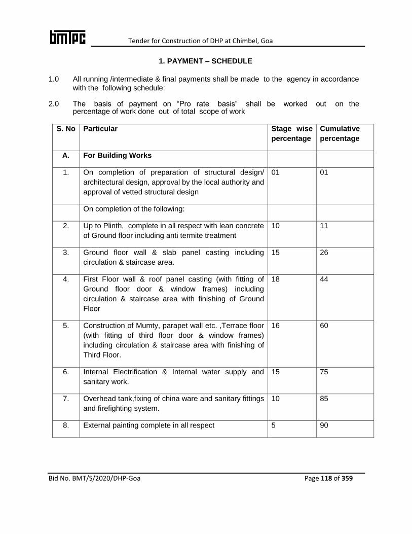
Tender for Construction of DHP at Chimbel, Goa
Bid No. BMT/S/2020/DHP-Goa Page 118 of 359
1. PAYMENT – SCHEDULE
1.0 All running /intermediate & final payments shall be made to the agency in accordance
with the following schedule: 2.0 The basis of payment on “Pro rate basis” shall be worked out on the
percentage of work done out of total scope of work
S. No Particular Stage wise
percentage
Cumulative
percentage
A. For Building Works
1. On completion of preparation of structural design/
architectural design, approval by the local authority and
approval of vetted structural design
01 01
On completion of the following:
2. Up to Plinth, complete in all respect with lean concrete
of Ground floor including anti termite treatment
10 11
3. Ground floor wall & slab panel casting including
circulation & staircase area.
15 26
4. First Floor wall & roof panel casting (with fitting of
Ground floor door & window frames) including
circulation & staircase area with finishing of Ground
Floor
18 44
5. Construction of Mumty, parapet wall etc. ,Terrace floor
(with fitting of third floor door & window frames)
including circulation & staircase area with finishing of
Third Floor.
16 60
6. Internal Electrification & Internal water supply and
sanitary work.
15 75
7. Overhead tank,fixing of china ware and sanitary fittings
and firefighting system.
10 85
8. External painting complete in all respect 5 90

Tender for Construction of DHP at Chimbel, Goa
Bid No. BMT/S/2020/DHP-Goa Page 119 of 359
9. After site clearance, issuing of completion certificate
and handing over the houses
10 100
B. For Onsite infrastructure work Not exceeding three RA bills
for the completed item/s as
per actual measurements
For and On Behalf of BMTPC
Accepted by me
Signature of Agency & Seal
Name:___________________________
Address:_________________________
Tel No. __________________________
Fax No. __________________________
Email____________________________

Tender for Construction of DHP at Chimbel, Goa
Bid No. BMT/S/2020/DHP-Goa Page 120 of 359
Part-5
Financial Bid
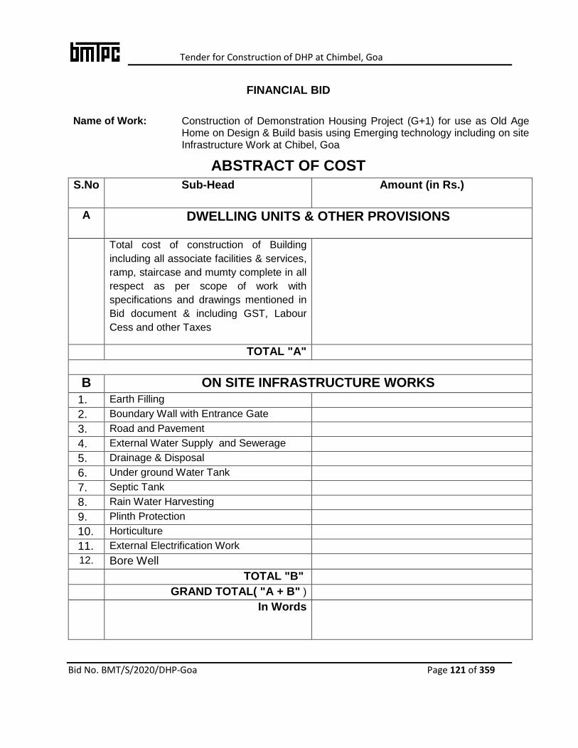
Tender for Construction of DHP at Chimbel, Goa
Bid No. BMT/S/2020/DHP-Goa Page 121 of 359
FINANCIAL BID
Name of Work: Construction of Demonstration Housing Project (G+1) for use as Old Age Home on Design & Build basis using Emerging technology including on site Infrastructure Work at Chibel, Goa
ABSTRACT OF COST
S.No Sub-Head Amount (in Rs.)
A DWELLING UNITS & OTHER PROVISIONS
Total cost of construction of Building
including all associate facilities & services,
ramp, staircase and mumty complete in all
respect as per scope of work with
specifications and drawings mentioned in
Bid document & including GST, Labour
Cess and other Taxes
TOTAL "A"
B ON SITE INFRASTRUCTURE WORKS
1. Earth Filling
2. Boundary Wall with Entrance Gate
3. Road and Pavement
4. External Water Supply and Sewerage
5. Drainage & Disposal
6. Under ground Water Tank
7. Septic Tank
8. Rain Water Harvesting
9. Plinth Protection
10. Horticulture
11. External Electrification Work
12. Bore Well
TOTAL "B"
GRAND TOTAL( "A + B" )
In Words

Tender for Construction of DHP at Chimbel, Goa
Bid No. BMT/S/2020/DHP-Goa Page 122 of 359
SCHEDULE OF QUANTITIES
A DWELLING UNITS AND OTHER PROVISIONS
Sl.
No.
Description of Work Quantity Unit Rate in Rs. Amount
(in Rs.)
1. Total cost of construction of
Building including all
associate facilities &
services, ramp, staircase
and mumty complete in all
respectas per scope of
work with specifications
and drawings mentioned in
Bid document & including
GST, Labour Cess and
other Taxes
1 L.S.
Note: Nothing extra shall be paid over and above the quoted rate. The rate is inclusive of all costs for completing the dwelling units & other provisions. The contractor shall be responsible for Executing all items required for completing the dwelling units and other provisions in all respect to make the same habitable & ready for occupation.
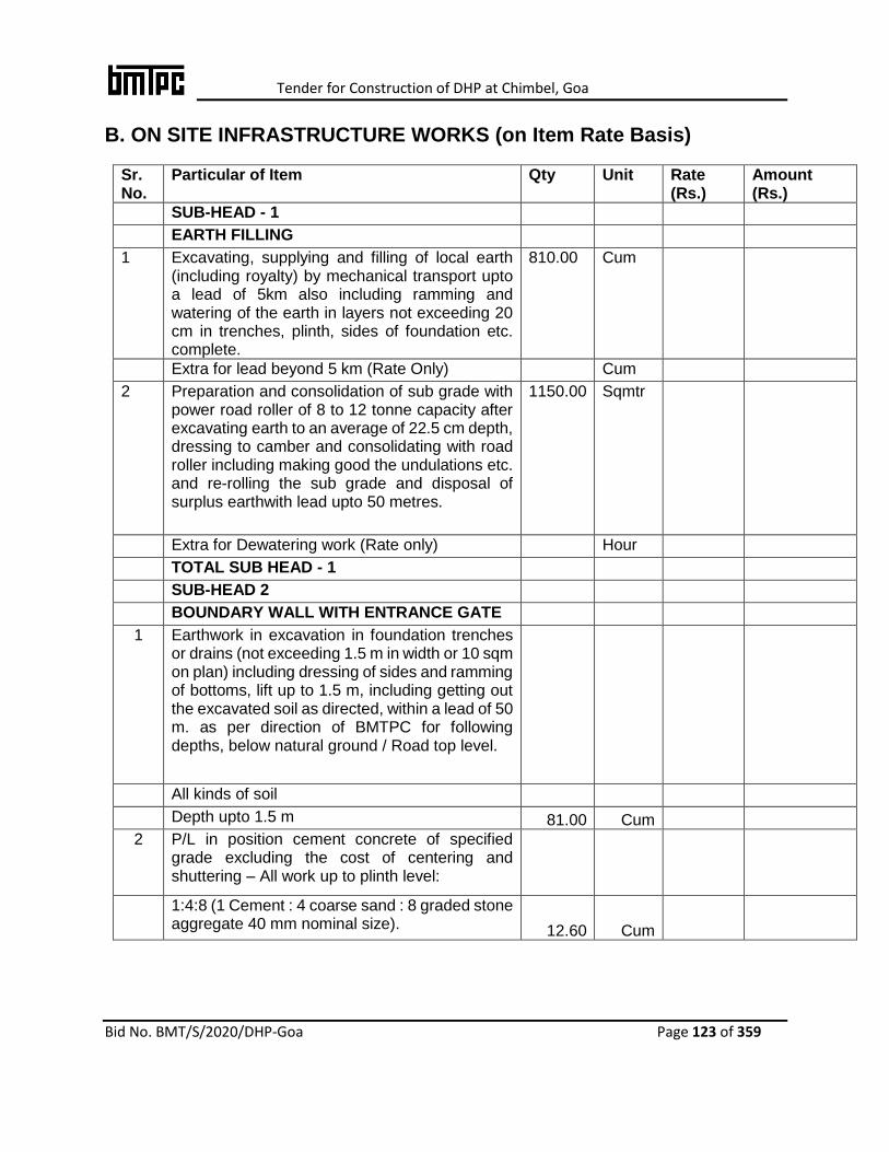
Tender for Construction of DHP at Chimbel, Goa
Bid No. BMT/S/2020/DHP-Goa Page 123 of 359
B. ON SITE INFRASTRUCTURE WORKS (on Item Rate Basis)
Sr. No.
Particular of Item Qty Unit Rate (Rs.)
Amount (Rs.)
SUB-HEAD - 1
EARTH FILLING
1 Excavating, supplying and filling of local earth (including royalty) by mechanical transport upto a lead of 5km also including ramming and watering of the earth in layers not exceeding 20 cm in trenches, plinth, sides of foundation etc. complete.
810.00 Cum
Extra for lead beyond 5 km (Rate Only) Cum
2 Preparation and consolidation of sub grade with power road roller of 8 to 12 tonne capacity after excavating earth to an average of 22.5 cm depth, dressing to camber and consolidating with road roller including making good the undulations etc. and re-rolling the sub grade and disposal of surplus earthwith lead upto 50 metres.
1150.00 Sqmtr
Extra for Dewatering work (Rate only) Hour
TOTAL SUB HEAD - 1
SUB-HEAD 2
BOUNDARY WALL WITH ENTRANCE GATE
1 Earthwork in excavation in foundation trenches or drains (not exceeding 1.5 m in width or 10 sqm on plan) including dressing of sides and ramming of bottoms, lift up to 1.5 m, including getting out the excavated soil as directed, within a lead of 50 m. as per direction of BMTPC for following depths, below natural ground / Road top level.
All kinds of soil
Depth upto 1.5 m 81.00 Cum
2 P/L in position cement concrete of specified grade excluding the cost of centering and shuttering – All work up to plinth level:
1:4:8 (1 Cement : 4 coarse sand : 8 graded stone aggregate 40 mm nominal size). 12.60 Cum
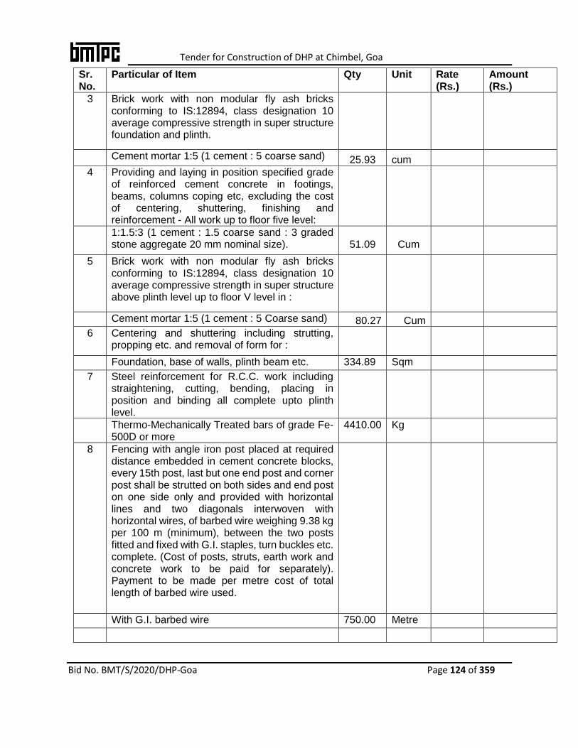
Tender for Construction of DHP at Chimbel, Goa
Bid No. BMT/S/2020/DHP-Goa Page 124 of 359
Sr. No.
Particular of Item Qty Unit Rate (Rs.)
Amount (Rs.)
3 Brick work with non modular fly ash bricks conforming to IS:12894, class designation 10 average compressive strength in super structure foundation and plinth.
Cement mortar 1:5 (1 cement : 5 coarse sand) 25.93 cum
4 Providing and laying in position specified grade of reinforced cement concrete in footings, beams, columns coping etc, excluding the cost of centering, shuttering, finishing and reinforcement - All work up to floor five level:
1:1.5:3 (1 cement : 1.5 coarse sand : 3 graded stone aggregate 20 mm nominal size).
51.09
Cum
5 Brick work with non modular fly ash bricks conforming to IS:12894, class designation 10 average compressive strength in super structure above plinth level up to floor V level in :
Cement mortar 1:5 (1 cement : 5 Coarse sand) 80.27 Cum
6 Centering and shuttering including strutting, propping etc. and removal of form for :
Foundation, base of walls, plinth beam etc. 334.89 Sqm
7 Steel reinforcement for R.C.C. work including straightening, cutting, bending, placing in position and binding all complete upto plinth level.
Thermo-Mechanically Treated bars of grade Fe-500D or more
4410.00 Kg
8 Fencing with angle iron post placed at required distance embedded in cement concrete blocks, every 15th post, last but one end post and corner post shall be strutted on both sides and end post on one side only and provided with horizontal lines and two diagonals interwoven with horizontal wires, of barbed wire weighing 9.38 kg per 100 m (minimum), between the two posts fitted and fixed with G.I. staples, turn buckles etc. complete. (Cost of posts, struts, earth work and concrete work to be paid for separately). Payment to be made per metre cost of total length of barbed wire used.
With G.I. barbed wire 750.00 Metre

Tender for Construction of DHP at Chimbel, Goa
Bid No. BMT/S/2020/DHP-Goa Page 125 of 359
Sr. No.
Particular of Item Qty Unit Rate (Rs.)
Amount (Rs.)
9 Supplying at site Angle iron post & strut of required size including bottom to be split and bent at right angle in opposite direction for 10 cm length and drilling holes upto 10 mm dia. etc. complete.
465.00 Kg.
10 Painting with synthetic enamel paint of approved brand and manufacture of required colour to give an even shade :
Two or more coats on new work over an under coat of approved priming coat
50.00 Sqm.
11 12 mm cement plaster of mix :
1:6 (1 cement: 6 coarse sand) 790.00 Sqm
12 Finishing walls with water proofing cement paint of required shade :
New work (Two or more coats applied @ 3.84 kg/10 sqm) 790.00 Sqm
14 Steel work welded in built up sections/framed work including cutting hoisting, rixing in position and applying a priming coat of approved steel primer using structural steel, etc. as required.
Entrance Gate 400.00 Kg
TOTAL SUB-HEAD 2
SUB-HEAD - 3
ROAD AND PAVEMENT
1 Earth work in excavation by mechanical means (Hydraulic excavator)/manual means over areas (exceeding 30 cm in depth, 1.5 m in width as well as 10 sqm on plan) including getting out and disposal of excavated earth lead upto 50 m and lift upto 1.5 m, as directed by BMTPC
All kinds of soil 95.00 Cum
2 Brick work with common burnt clay F.P.S. (non modular) bricks of class designation 7.5 in foundation and plinth in:
Cement mortar 1:6 (1 cement : 6 coarse sand) 18.63 cum
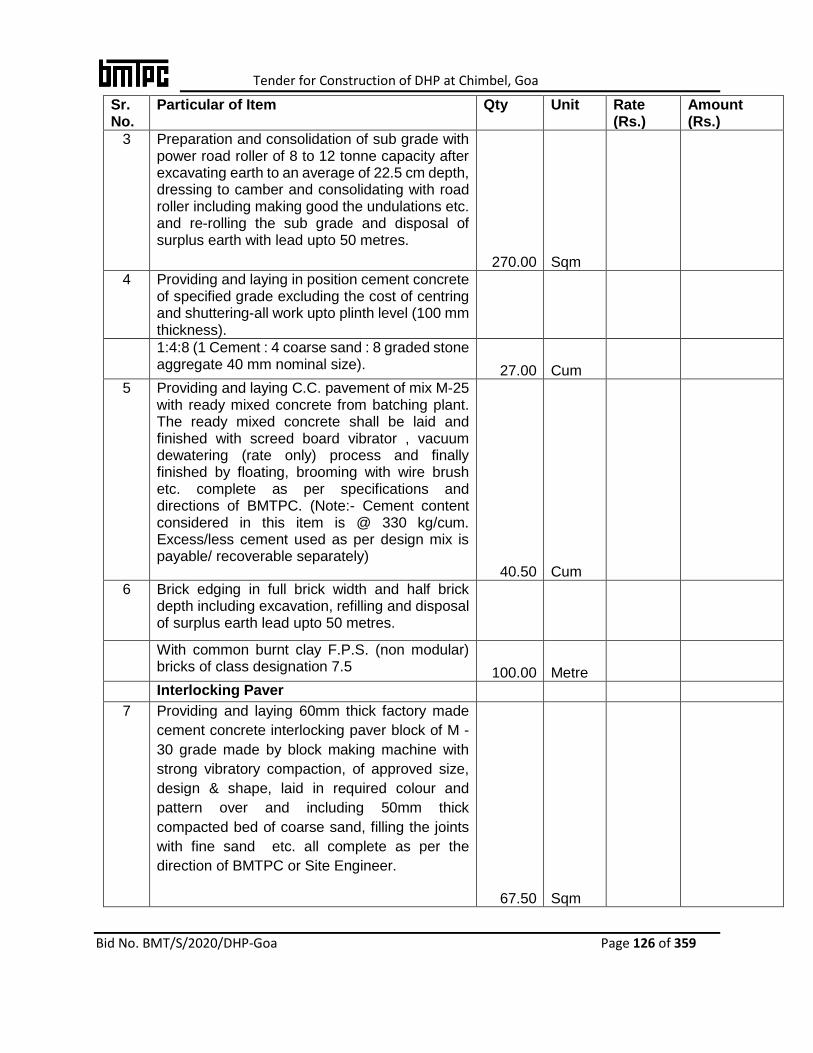
Tender for Construction of DHP at Chimbel, Goa
Bid No. BMT/S/2020/DHP-Goa Page 126 of 359
Sr. No.
Particular of Item Qty Unit Rate (Rs.)
Amount (Rs.)
3 Preparation and consolidation of sub grade with power road roller of 8 to 12 tonne capacity after excavating earth to an average of 22.5 cm depth, dressing to camber and consolidating with road roller including making good the undulations etc. and re-rolling the sub grade and disposal of surplus earth with lead upto 50 metres.
270.00 Sqm
4 Providing and laying in position cement concrete of specified grade excluding the cost of centring and shuttering-all work upto plinth level (100 mm thickness).
1:4:8 (1 Cement : 4 coarse sand : 8 graded stone aggregate 40 mm nominal size). 27.00 Cum
5 Providing and laying C.C. pavement of mix M-25 with ready mixed concrete from batching plant. The ready mixed concrete shall be laid and finished with screed board vibrator , vacuum dewatering (rate only) process and finally finished by floating, brooming with wire brush etc. complete as per specifications and directions of BMTPC. (Note:- Cement content considered in this item is @ 330 kg/cum. Excess/less cement used as per design mix is payable/ recoverable separately)
40.50 Cum
6 Brick edging in full brick width and half brick depth including excavation, refilling and disposal of surplus earth lead upto 50 metres.
With common burnt clay F.P.S. (non modular) bricks of class designation 7.5 100.00 Metre
Interlocking Paver
7 Providing and laying 60mm thick factory made
cement concrete interlocking paver block of M -
30 grade made by block making machine with
strong vibratory compaction, of approved size,
design & shape, laid in required colour and
pattern over and including 50mm thick
compacted bed of coarse sand, filling the joints
with fine sand etc. all complete as per the
direction of BMTPC or Site Engineer.
67.50 Sqm

Tender for Construction of DHP at Chimbel, Goa
Bid No. BMT/S/2020/DHP-Goa Page 127 of 359
Sr. No.
Particular of Item Qty Unit Rate (Rs.)
Amount (Rs.)
TOTAL SUB HEAD - 3
SUB-HEAD 4
EXTERNAL WATER SUPPLY AND SEWERAGE
1 Providing and fixing Chlorinated Polyvinyl Chloride (CPVC) pipes, having thermal stability for hot & cold water supply including all CPVC plain & brass threaded fittings This includes jointing of pipes & fittings with one step CPVC solvent cement, trenching, refilling & testing of joints complete as per direction of BMTPC.
50 mm nominal outer dia Pipes 140.00 Metre
32 mm nominal outer dia pipes 60.00 Metre
2 Providing and fixing brass ferrule with C.I. mouth cover including boring and tapping the main :
20 mm nominal bore 10.00 Each
3 Providing and fixing gun metal gate valve with C.I. wheel of approved quality (screwed end) :
50 mm nominal bore. 4.00 Each
SEWERAGE
4 Earth work in excavation by mechanical means (Hydraulic excavator) /manual means in foundation trenches or drains (not exceeding 1.5 m in width or 10 sqm on plan), including dressing of sides and ramming of bottoms, lift upto 1.5 m, including getting out the excavated soil and disposal of surplus excavated soil as directed, within a lead of 50 m.
All kinds of soil. 65.40 cum
5 Providing and fixing square-mouth S.W. gully trap grade 'A'’ complete with Precast RCC cover and frame of approved make 300 x 300 mm internal size:
100x 100 size P Type
With bricks class designation 75 13.00 Each
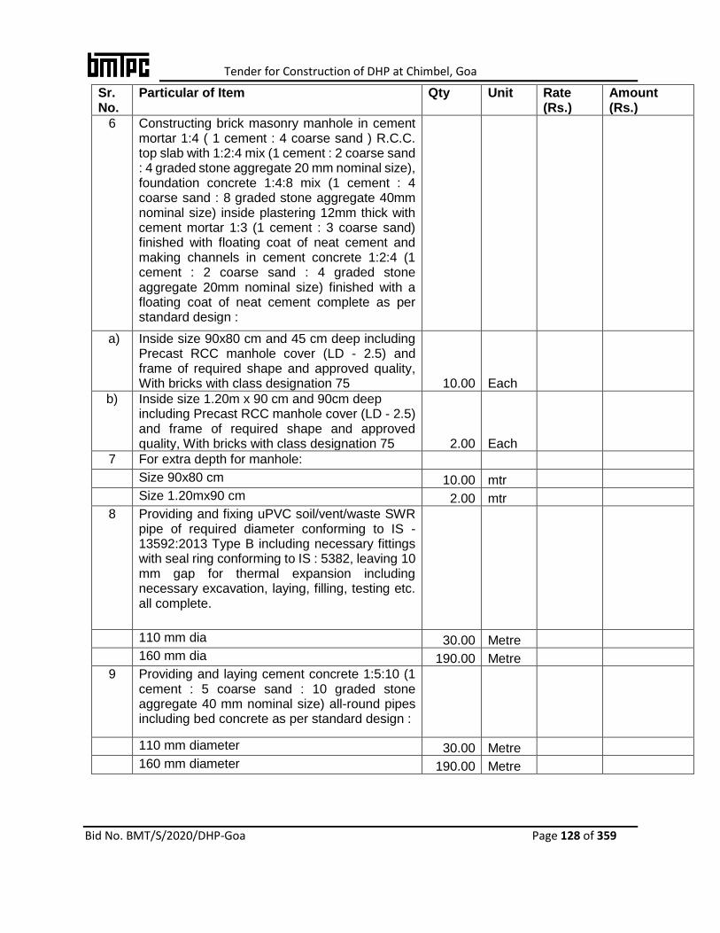
Tender for Construction of DHP at Chimbel, Goa
Bid No. BMT/S/2020/DHP-Goa Page 128 of 359
Sr. No.
Particular of Item Qty Unit Rate (Rs.)
Amount (Rs.)
6 Constructing brick masonry manhole in cement mortar 1:4 ( 1 cement : 4 coarse sand ) R.C.C. top slab with 1:2:4 mix (1 cement : 2 coarse sand : 4 graded stone aggregate 20 mm nominal size), foundation concrete 1:4:8 mix (1 cement : 4 coarse sand : 8 graded stone aggregate 40mm nominal size) inside plastering 12mm thick with cement mortar 1:3 (1 cement : 3 coarse sand) finished with floating coat of neat cement and making channels in cement concrete 1:2:4 (1 cement : 2 coarse sand : 4 graded stone aggregate 20mm nominal size) finished with a floating coat of neat cement complete as per standard design :
a) Inside size 90x80 cm and 45 cm deep including Precast RCC manhole cover (LD - 2.5) and frame of required shape and approved quality, With bricks with class designation 75 10.00 Each
b) Inside size 1.20m x 90 cm and 90cm deep including Precast RCC manhole cover (LD - 2.5) and frame of required shape and approved quality, With bricks with class designation 75 2.00 Each
7 For extra depth for manhole:
Size 90x80 cm 10.00 mtr
Size 1.20mx90 cm 2.00 mtr
8 Providing and fixing uPVC soil/vent/waste SWR pipe of required diameter conforming to IS - 13592:2013 Type B including necessary fittings with seal ring conforming to IS : 5382, leaving 10 mm gap for thermal expansion including necessary excavation, laying, filling, testing etc. all complete.
110 mm dia 30.00 Metre
160 mm dia 190.00 Metre
9 Providing and laying cement concrete 1:5:10 (1 cement : 5 coarse sand : 10 graded stone aggregate 40 mm nominal size) all-round pipes including bed concrete as per standard design :
110 mm diameter 30.00 Metre
160 mm diameter 190.00 Metre

Tender for Construction of DHP at Chimbel, Goa
Bid No. BMT/S/2020/DHP-Goa Page 129 of 359
Sr. No.
Particular of Item Qty Unit Rate (Rs.)
Amount (Rs.)
10 Making connection of drain or sewer line with existing manhole including breaking into and making good the walls, floors with cement concrete 1:2:4 mix (1 cement : 2 coarse sand : 4 graded stone aggregate 20 mm nominal size) cement plastered on both sides with cement mortar 1:3 (1 cement : 3 coarse sand), finished with a floating coat of neat cement and making necessary channels for the drain etc. complete :
Pipes 100 to 250 mm diameter 1.00 Each
TOTAL SUB-HEAD 4
SUB-HEAD 5
DRAINAGE AND DISPOSAL
1 Earth work in excavation by mechanical means (Hydraulic excavator) / manual means in foundation trenches or drains (not exceeding 1.5 m in width or 10 sqm on plan), including dressing of sides and ramming of bottoms, lift upto 1.5 m, including getting out the excavated soil and disposal of surplus excavated soil as directed, within a lead of 50 m.
All kinds of soil.
Depth upto 1.5 m 75.60 Cum
2 Providing and laying in position cement concrete of specified grade excluding the cost of centring and shuttering-all work upto plinth level.
1:4:8 (1 Cement : 4 coarse sand : 8 graded stone aggregate 40 mm nominal size). 7.50 cum
3 Brick work with common burnt clay F.P.S. (non modular) bricks of class designation 7.5 in foundation and plinth in:
Cement mortar 1:6 (1 cement : 6 coarse sand) 14.49 Cum
4 12 mm cement plaster finished with a floating coat of neat cement of mix :
1:4 (1 cement: 4 fine sand) 232.40 Sqm

Tender for Construction of DHP at Chimbel, Goa
Bid No. BMT/S/2020/DHP-Goa Page 130 of 359
Sr. No.
Particular of Item Qty Unit Rate (Rs.)
Amount (Rs.)
5 Providing and fixing uPVC soil/vent/waste SWR pipe of required diameter conforming to IS - 13592:2013 Type B including necessary fittings with seal ring conforming to IS : 5382, leaving 10 mm gap for thermal expansion including necessary excavation, laying, filling, testing etc. all complete.
110 mm dia 81.00 Metre
160 mm dia 10.00 Metre
6 Providing and fixing factory made precast RCC perforated drain covers, having concrete of strength not less than M-25, of size 1000 x 450x50 mm, reinforced with 8 mm dia four nos longitudinal & 9 nos cross sectional T.M.T. hoop bars, including providing 50 mm dia perforations @ 100 to 125 mm c/c, including providing edge binding with M.S. flats of size 50 mm x 1.6 mm complete, all as per direction of BMTPC. 140.00 Each
TOTAL SUB-HEAD 5
SUB-HEAD 6
UNDER GROUND WATER TANK (5.00 M X 2.50 M X 1.8 M)
1 Earth work in excavation by mechanical means
(Hydraulic excavator)/manual means over areas
(exceeding 30 cm in depth, 1.5 m in width as well
as 10 sqm on plan) including getting out and
disposal of excavated earth lead upto 50 m and
lift upto 1.5 m, as directed by Engineer-in-
charge. Depth upto 1.5 m
All kinds of soil
Depth upto 1.5 m 30.00 Cum
2 Providing and laying in position cement concrete of specified grade excluding the cost of centring and shuttering - All work upto plinth level :
1:4:8 (1 Cement : 4 coarse sand : 8 graded stone aggregate 40 mm nominal size). 1.50 Cum
1:2:4 (1 cement : 2 coarse sand : 4 graded stone aggregate 20 mm nominal size21) 1.20 Cum
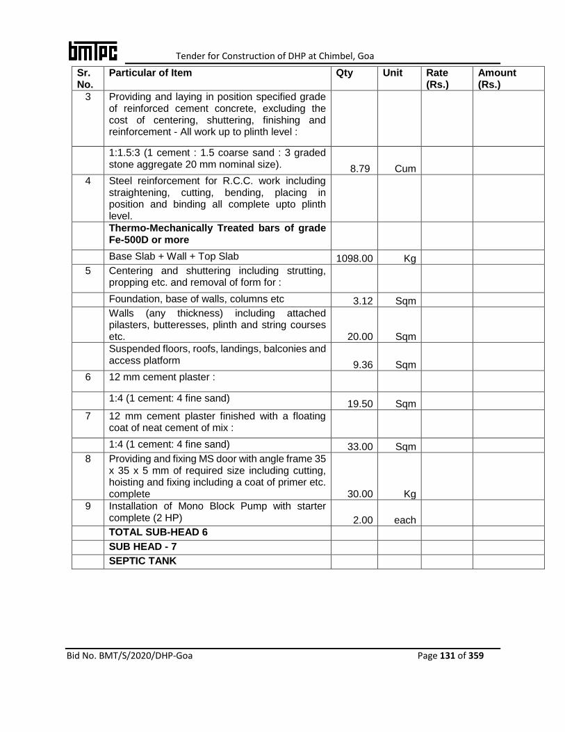
Tender for Construction of DHP at Chimbel, Goa
Bid No. BMT/S/2020/DHP-Goa Page 131 of 359
Sr. No.
Particular of Item Qty Unit Rate (Rs.)
Amount (Rs.)
3 Providing and laying in position specified grade of reinforced cement concrete, excluding the cost of centering, shuttering, finishing and reinforcement - All work up to plinth level :
1:1.5:3 (1 cement : 1.5 coarse sand : 3 graded stone aggregate 20 mm nominal size). 8.79 Cum
4 Steel reinforcement for R.C.C. work including straightening, cutting, bending, placing in position and binding all complete upto plinth level.
Thermo-Mechanically Treated bars of grade Fe-500D or more
Base Slab + Wall + Top Slab 1098.00 Kg
5 Centering and shuttering including strutting, propping etc. and removal of form for :
Foundation, base of walls, columns etc 3.12 Sqm
Walls (any thickness) including attached pilasters, butteresses, plinth and string courses etc. 20.00 Sqm
Suspended floors, roofs, landings, balconies and access platform 9.36 Sqm
6 12 mm cement plaster :
1:4 (1 cement: 4 fine sand) 19.50 Sqm
7 12 mm cement plaster finished with a floating coat of neat cement of mix :
1:4 (1 cement: 4 fine sand) 33.00 Sqm
8 Providing and fixing MS door with angle frame 35 x 35 x 5 mm of required size including cutting, hoisting and fixing including a coat of primer etc. complete 30.00 Kg
9 Installation of Mono Block Pump with starter complete (2 HP) 2.00 each
TOTAL SUB-HEAD 6
SUB HEAD - 7
SEPTIC TANK

Tender for Construction of DHP at Chimbel, Goa
Bid No. BMT/S/2020/DHP-Goa Page 132 of 359
Sr. No.
Particular of Item Qty Unit Rate (Rs.)
Amount (Rs.)
1 Earth work in excavation by mechanical means
(Hydraulic excavator)/manual means over areas
(exceeding 30 cm in depth, 1.5 m in width as well
as 10sqm on plan) including getting out and
disposal of excavated earth lead upto 50 m and
lift upto 1.5 m, as directed by Engineer-in-
charge.
All kinds of soil 30.20 cum
Extra for additional depth of 1.5 m or part thereof
20.13 cum
2 Providing and laying in position cement concrete of specified grade exluding the cost of centring and shuttering-all work upto plinth level.
1:4:8 (1 Cement : 4 coarse sand : 8 graded stone aggregate 40 mm nominal size). 2.00 cum
3 Brick work with common burnt clay F.P.S. (non modular) bricks of class designation 7.5 in foundation and plinth in:
Cement mortar 1:6 (1 cement : 6 coarse sand) 8.87 cum
4 Providing and laying in position cement concrete of specified grade excluding the cost of centring and shuttering - All work upto plinth level :
1:2:4 (1 cement : 2 coarse sand : 4 graded stone aggregate 20 mm nominal size21) 1.20 Cum
5 Providing and laying in position specified grade of reinforced cement concrete, excluding the cost of centering, shuttering, finishing and reinforcement - All work up to plinth level :
1:1.5:3 (1 cement : 1.5 coarse sand : 3 graded stone aggregate 20 mm nominal size). 2.27 Cum
6 Steel reinforcement for R.C.C. work including straightening, cutting, bending, placing in position and binding all complete upto plinth level.
Thermo-Mechanically Treated bars of grade Fe-500D or more 283.00 Kg
7 Centering and shuttering including strutting, propping etc. and removal of form for :

Tender for Construction of DHP at Chimbel, Goa
Bid No. BMT/S/2020/DHP-Goa Page 133 of 359
Sr. No.
Particular of Item Qty Unit Rate (Rs.)
Amount (Rs.)
Suspended floors, roofs, landings, balconies and access platform 11.90 Sqm
8 Half brick masonry with common burnt clay F.P.S. (non modular) bricks of class designation 7.5 in foundations and plinth in
cement mortar 1:4 (1 cement : 4 coarse sand) sqm 2.50 sqm
9 12 mm cement plaster finished with a floating coat of neat cement of mix :
1:4 (1 cement: 4 fine sand) 36.25 Sqm
10 Providing and fixing MS door with angle frame 35 x 35 x 5 mm of required size including cutting, hoisting and fixing including a coat of primer etc. complete
30.00 Kg
11 Making soak pit. 2.5 m dia 3 m deep with 45x45 cm dry brick honey comb shaft and S.W. drain pipe 100 mm diameter, 1.8 m long complete filled with laterite stone aggregate 125 to 180 mm surrounded by laterite stone aggregate of 40mm and down gauge as per standard design. (Top level of soak pit to be maintained with reference to the outlet pipe from septic tank) 1 No
TOTAL SUB-HEAD 7
SUB-HEAD 8
RAIN WATER HARVESTING
1 Boring/drilling bore well of required dia for casing/ strainer pipe, by suitable method prescribed in IS: 2800 (part I), including collecting samples from different strata, preparing and submitting strata chart/ bore log, including hire & running charges of all equipments, tools, plants & machineries required for the job, all complete as per direction of BMTPC, upto 90 metre depth below ground level.
In all type of soil
300mm dia 50.00 Metre
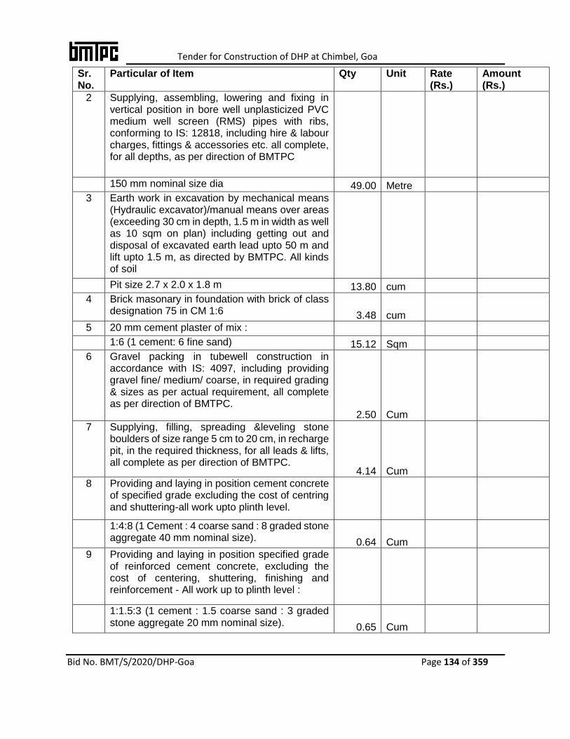
Tender for Construction of DHP at Chimbel, Goa
Bid No. BMT/S/2020/DHP-Goa Page 134 of 359
Sr. No.
Particular of Item Qty Unit Rate (Rs.)
Amount (Rs.)
2 Supplying, assembling, lowering and fixing in vertical position in bore well unplasticized PVC medium well screen (RMS) pipes with ribs, conforming to IS: 12818, including hire & labour charges, fittings & accessories etc. all complete, for all depths, as per direction of BMTPC
150 mm nominal size dia 49.00 Metre
3 Earth work in excavation by mechanical means (Hydraulic excavator)/manual means over areas (exceeding 30 cm in depth, 1.5 m in width as well as 10 sqm on plan) including getting out and disposal of excavated earth lead upto 50 m and lift upto 1.5 m, as directed by BMTPC. All kinds of soil
Pit size 2.7 x 2.0 x 1.8 m 13.80 cum
4 Brick masonary in foundation with brick of class designation 75 in CM 1:6 3.48 cum
5 20 mm cement plaster of mix :
1:6 (1 cement: 6 fine sand) 15.12 Sqm
6 Gravel packing in tubewell construction in accordance with IS: 4097, including providing gravel fine/ medium/ coarse, in required grading & sizes as per actual requirement, all complete as per direction of BMTPC.
2.50 Cum
7 Supplying, filling, spreading &leveling stone boulders of size range 5 cm to 20 cm, in recharge pit, in the required thickness, for all leads & lifts, all complete as per direction of BMTPC.
4.14 Cum
8 Providing and laying in position cement concrete of specified grade excluding the cost of centring and shuttering-all work upto plinth level.
1:4:8 (1 Cement : 4 coarse sand : 8 graded stone aggregate 40 mm nominal size). 0.64 Cum
9 Providing and laying in position specified grade of reinforced cement concrete, excluding the cost of centering, shuttering, finishing and reinforcement - All work up to plinth level :
1:1.5:3 (1 cement : 1.5 coarse sand : 3 graded stone aggregate 20 mm nominal size). 0.65 Cum
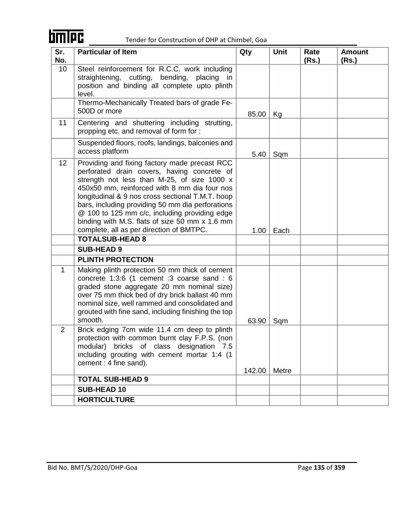
Tender for Construction of DHP at Chimbel, Goa
Bid No. BMT/S/2020/DHP-Goa Page 135 of 359
Sr. No.
Particular of Item Qty Unit Rate (Rs.)
Amount (Rs.)
10 Steel reinforcement for R.C.C. work including straightening, cutting, bending, placing in position and binding all complete upto plinth level.
Thermo-Mechanically Treated bars of grade Fe-500D or more 85.00 Kg
11 Centering and shuttering including strutting, propping etc. and removal of form for :
Suspended floors, roofs, landings, balconies and access platform 5.40 Sqm
12 Providing and fixing factory made precast RCC perforated drain covers, having concrete of strength not less than M-25, of size 1000 x 450x50 mm, reinforced with 8 mm dia four nos longitudinal & 9 nos cross sectional T.M.T. hoop bars, including providing 50 mm dia perforations @ 100 to 125 mm c/c, including providing edge binding with M.S. flats of size 50 mm x 1.6 mm complete, all as per direction of BMTPC. 1.00 Each
TOTALSUB-HEAD 8
SUB-HEAD 9
PLINTH PROTECTION
1 Making plinth protection 50 mm thick of cement concrete 1:3:6 (1 cement :3 coarse sand : 6 graded stone aggregate 20 mm nominal size) over 75 mm thick bed of dry brick ballast 40 mm nominal size, well rammed and consolidated and grouted with fine sand, including finishing the top smooth. 63.90 Sqm
2 Brick edging 7cm wide 11.4 cm deep to plinth protection with common burnt clay F.P.S. (non modular) bricks of class designation 7.5 including grouting with cement mortar 1:4 (1 cement : 4 fine sand).
142.00 Metre
TOTAL SUB-HEAD 9
SUB-HEAD 10
HORTICULTURE

Tender for Construction of DHP at Chimbel, Goa
Bid No. BMT/S/2020/DHP-Goa Page 136 of 359
Sr. No.
Particular of Item Qty Unit Rate (Rs.)
Amount (Rs.)
1 Supplying and stacking at site dump manure from approved source including all lead and lifts (manure measured in stacks will be reduced by 8% for payment) - screened through sieve of IS designation 20 mm.
14.00 Cum
2 Supplying & stacking sludge at site including royalty & carriage will all leads & lifts (sludge manure measured in stacks will be reduced by 8 % for payment) 14.00 Cum
3 Spreading of sludge / damp manure of / and good earth in required thickness (cost of sludge/ damp manure or / land good earth to paid separately) 15.00 Cum
4 Grassing with selection No. 1 grass including watering and maintenance of the lawn for 60 days or more till the grass forms a thick lawn, free from weeds and fit for mowing including supplying good earth.
In rows 15 cm apart in either direction 140.00 Sqm
5 Supplying and stacking of good earth at site including royalty and carriage upto 5 km complete (earth measured in stacks will be reduced by 20% for payment).
28.00 Cum
6 Supplying & Stacking of Selection No.1 doob grass at site fresh & free from weeds having proper roots in green including loading, unloading, carriage and all taxes paid etc. and as per direction of officer in charge.
140.00 Sqm
7 Supply and Planting of Croton Golden plant, having ht. 45 cm to 60 cm with 2 to 3 branches, well developed, fresh and healthy foliage in 25 cm size of Earthen pot / Plastic pot as per direction of the officer-in-charge.
Plants 40.00 Each
TOTAL SUB-HEAD 10
SUB-HEAD 11
EXTERNAL ELECTRIFICATION

Tender for Construction of DHP at Chimbel, Goa
Bid No. BMT/S/2020/DHP-Goa Page 137 of 359
Sr. No.
Particular of Item Qty Unit Rate (Rs.)
Amount (Rs.)
1 P/Laying XLPE insulated / P.V.C. sheathed cable of 1.1 KV grade with aluminium conductor Armoured of IS:7098-I/1554-1 approved make in ground as per IS:1255 including excavation of 30cmx75cm size trench, 25 cm thick under layer of sand, IInd class bricks covering, refilling earth, compaction of earth, making necessary connection, testing etc. as required of size.
35.0 Sq.mm 50.00 Metre
3.5 core
6.0 Sq.mm 300.00 Metre
2 core
2 Supplying and making one end termination with heavy duty single compression brass gland SIBG type, aluminium lugs duly crimped with crimping tool, PVC tape etc for following size of Armoured PVC insulated & PVC sheathed/ XLPE aluminium conductor cable of 1.1 KV grade as required of size.
3.5 x 35.0 sq.mm 6 Set
2 x 6.0 sq.mm 30 Set
Feeder Pillar
3 Supply and fixing of floor mounting, totally enclosed, compartmentalized, cubical, dust, vermin proof and outdoor type. Feeder pillar fabricated out of 2 mm thick cold rolled carbon annealed, sheet steel, internally strengthened with angle iron frame work with following incoming and outgoing feeders (fabricated out of 2 mm CRCA Sheet steel) including making connection / inter-connections with lugs / glands crimping tools, testing and commissioning of following items inside the panel:
Incommer
1 No. 200 Amp. 4 poles MCCB (25 Ka) with ON/OFF indications metre
Indication
Three (3) Nos. phase indicating (R.Y and B) lamps with protection 2A SP MCB's for protection having lens and lamp.
Outgoing
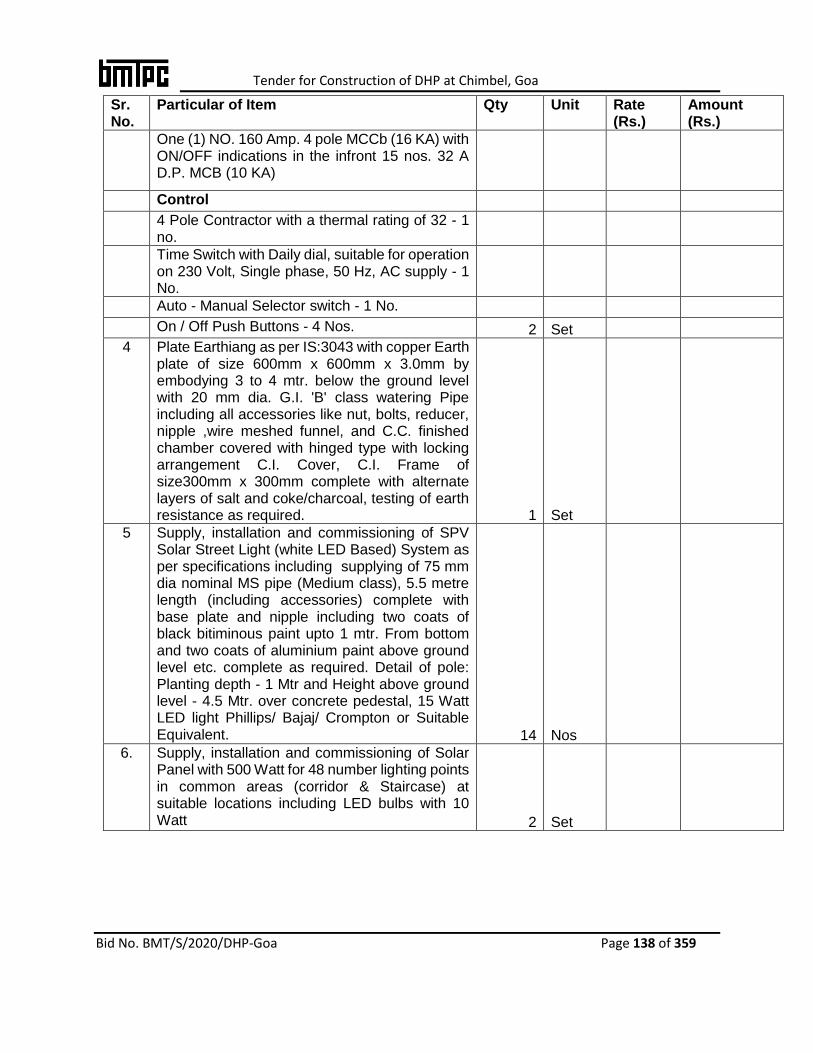
Tender for Construction of DHP at Chimbel, Goa
Bid No. BMT/S/2020/DHP-Goa Page 138 of 359
Sr. No.
Particular of Item Qty Unit Rate (Rs.)
Amount (Rs.)
One (1) NO. 160 Amp. 4 pole MCCb (16 KA) with ON/OFF indications in the infront 15 nos. 32 A D.P. MCB (10 KA)
Control
4 Pole Contractor with a thermal rating of 32 - 1 no.
Time Switch with Daily dial, suitable for operation on 230 Volt, Single phase, 50 Hz, AC supply - 1 No.
Auto - Manual Selector switch - 1 No.
On / Off Push Buttons - 4 Nos. 2 Set
4 Plate Earthiang as per IS:3043 with copper Earth plate of size 600mm x 600mm x 3.0mm by embodying 3 to 4 mtr. below the ground level with 20 mm dia. G.I. 'B' class watering Pipe including all accessories like nut, bolts, reducer, nipple ,wire meshed funnel, and C.C. finished chamber covered with hinged type with locking arrangement C.I. Cover, C.I. Frame of size300mm x 300mm complete with alternate layers of salt and coke/charcoal, testing of earth resistance as required. 1 Set
5 Supply, installation and commissioning of SPV Solar Street Light (white LED Based) System as per specifications including supplying of 75 mm dia nominal MS pipe (Medium class), 5.5 metre length (including accessories) complete with base plate and nipple including two coats of black bitiminous paint upto 1 mtr. From bottom and two coats of aluminium paint above ground level etc. complete as required. Detail of pole: Planting depth - 1 Mtr and Height above ground level - 4.5 Mtr. over concrete pedestal, 15 Watt LED light Phillips/ Bajaj/ Crompton or Suitable Equivalent. 14 Nos
6. Supply, installation and commissioning of Solar Panel with 500 Watt for 48 number lighting points in common areas (corridor & Staircase) at suitable locations including LED bulbs with 10 Watt 2 Set
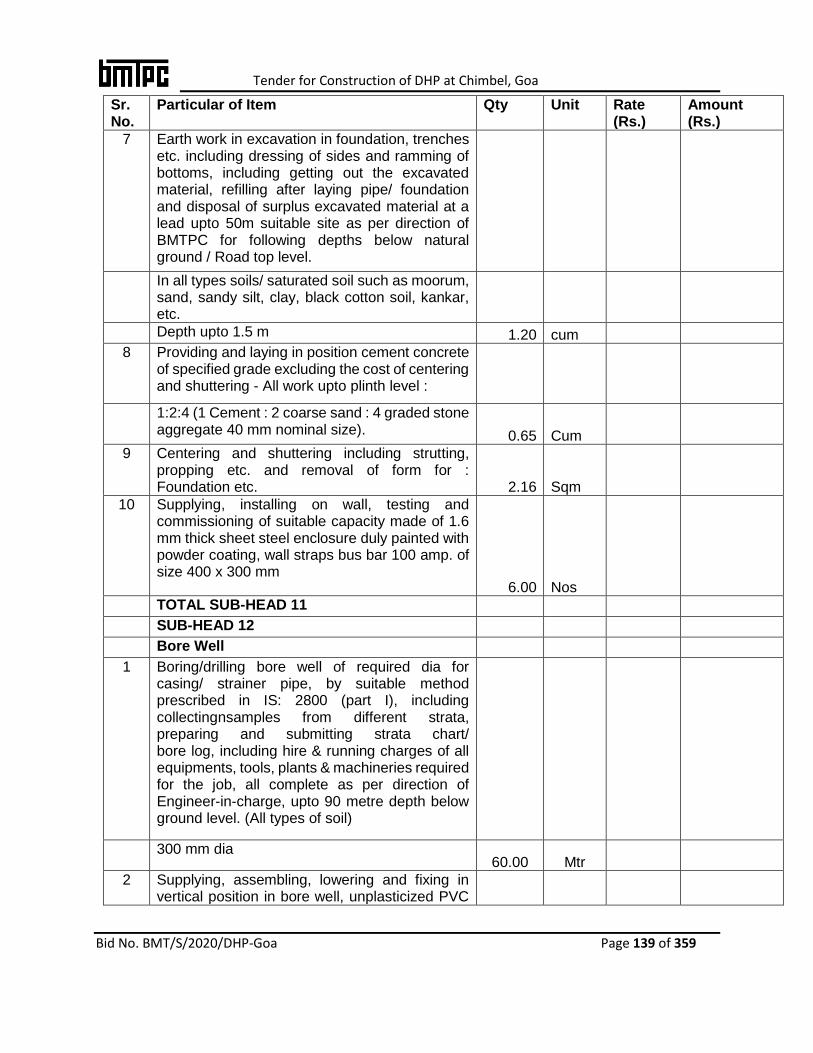
Tender for Construction of DHP at Chimbel, Goa
Bid No. BMT/S/2020/DHP-Goa Page 139 of 359
Sr. No.
Particular of Item Qty Unit Rate (Rs.)
Amount (Rs.)
7 Earth work in excavation in foundation, trenches etc. including dressing of sides and ramming of bottoms, including getting out the excavated material, refilling after laying pipe/ foundation and disposal of surplus excavated material at a lead upto 50m suitable site as per direction of BMTPC for following depths below natural ground / Road top level.
In all types soils/ saturated soil such as moorum, sand, sandy silt, clay, black cotton soil, kankar, etc.
Depth upto 1.5 m 1.20 cum
8 Providing and laying in position cement concrete of specified grade excluding the cost of centering and shuttering - All work upto plinth level :
1:2:4 (1 Cement : 2 coarse sand : 4 graded stone aggregate 40 mm nominal size). 0.65 Cum
9 Centering and shuttering including strutting, propping etc. and removal of form for : Foundation etc. 2.16 Sqm
10 Supplying, installing on wall, testing and commissioning of suitable capacity made of 1.6 mm thick sheet steel enclosure duly painted with powder coating, wall straps bus bar 100 amp. of size 400 x 300 mm
6.00 Nos
TOTAL SUB-HEAD 11
SUB-HEAD 12
Bore Well
1 Boring/drilling bore well of required dia for casing/ strainer pipe, by suitable method prescribed in IS: 2800 (part I), including collectingnsamples from different strata, preparing and submitting strata chart/ bore log, including hire & running charges of all equipments, tools, plants & machineries required for the job, all complete as per direction of Engineer-in-charge, upto 90 metre depth below ground level. (All types of soil)
300 mm dia 60.00 Mtr
2 Supplying, assembling, lowering and fixing in vertical position in bore well, unplasticized PVC
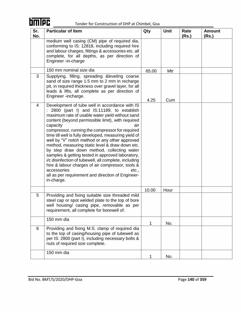
Tender for Construction of DHP at Chimbel, Goa
Bid No. BMT/S/2020/DHP-Goa Page 140 of 359
Sr. No.
Particular of Item Qty Unit Rate (Rs.)
Amount (Rs.)
medium well casing (CM) pipe of required dia, conforming to IS: 12818, including required hire and labour charges, fittings & accessories etc. all complete, for all depths, as per direction of Engineer -in-charge
150 mm nominal size dia 65.00 Mtr
3 Supplying, filling, spreading &leveling coarse sand of size range 1.5 mm to 2 mm in recharge pit, in required thickness over gravel layer, for all leads & lifts, all complete as per direction of Engineer -incharge.
4.25 Cum
4 Development of tube well in accordance with IS : 2800 (part I) and IS:11189, to establish maximum rate of usable water yield without sand content (beyond permissible limit), with required capacity air compressor, running the compressor for required time till well is fully developed, measuring yield of well by “V” notch method or any other approved method, measuring static level & draw down etc. by step draw down method, collecting water samples & getting tested in approved laboratory, i/c disinfection of tubewell, all complete, including hire & labour charges of air compressor, tools & accessories etc., all as per requirement and direction of Engineer-in-charge.
10.00 Hour
5 Providing and fixing suitable size threaded mild steel cap or spot welded plate to the top of bore well housing/ casing pipe, removable as per requirement, all complete for borewell of:
150 mm dia 1 No.
6 Providing and fixing M.S. clamp of required dia to the top of casing/housing pipe of tubewell as per IS: 2800 (part I), including necessary bolts & nuts of required size complete.
150 mm dia 1 No.
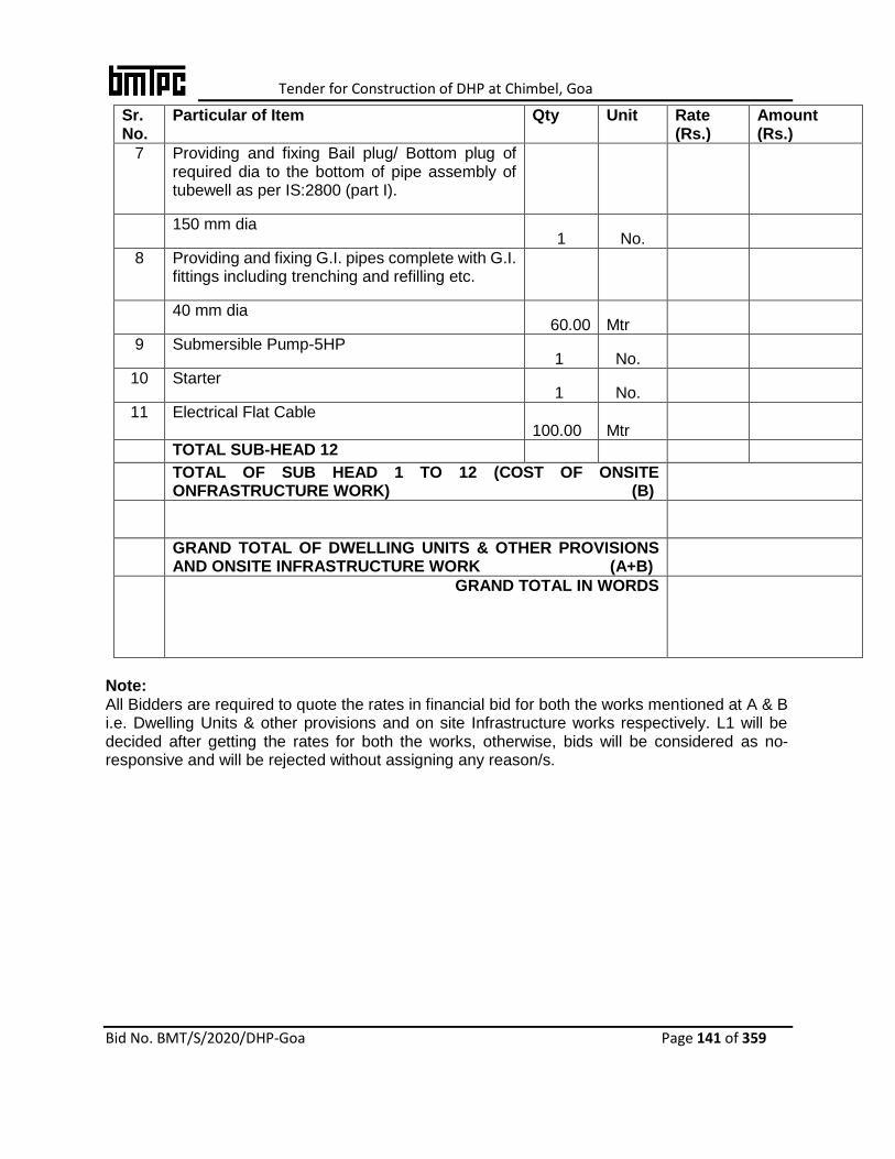
Tender for Construction of DHP at Chimbel, Goa
Bid No. BMT/S/2020/DHP-Goa Page 141 of 359
Sr. No.
Particular of Item Qty Unit Rate (Rs.)
Amount (Rs.)
7 Providing and fixing Bail plug/ Bottom plug of required dia to the bottom of pipe assembly of tubewell as per IS:2800 (part I).
150 mm dia 1 No.
8 Providing and fixing G.I. pipes complete with G.I. fittings including trenching and refilling etc.
40 mm dia 60.00 Mtr
9 Submersible Pump-5HP 1 No.
10 Starter 1 No.
11 Electrical Flat Cable 100.00 Mtr
TOTAL SUB-HEAD 12
TOTAL OF SUB HEAD 1 TO 12 (COST OF ONSITE ONFRASTRUCTURE WORK) (B)
GRAND TOTAL OF DWELLING UNITS & OTHER PROVISIONS AND ONSITE INFRASTRUCTURE WORK (A+B)
GRAND TOTAL IN WORDS
Note: All Bidders are required to quote the rates in financial bid for both the works mentioned at A & B i.e. Dwelling Units & other provisions and on site Infrastructure works respectively. L1 will be decided after getting the rates for both the works, otherwise, bids will be considered as no-responsive and will be rejected without assigning any reason/s.

Tender for Construction of DHP at Chimbel, Goa
Bid No. BMT/S/2020/DHP-Goa Page 142 of 359
Part-6
Soil Investigation Report
Tender for Construction of DHP at Chimbel, Goa
Bid No. BMT/S/2020/DHP-Goa Page 143 of 359
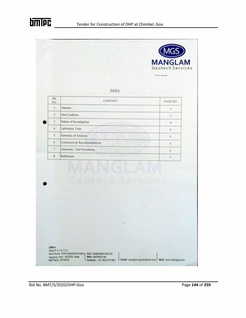
Tender for Construction of DHP at Chimbel, Goa
Bid No. BMT/S/2020/DHP-Goa Page 144 of 359
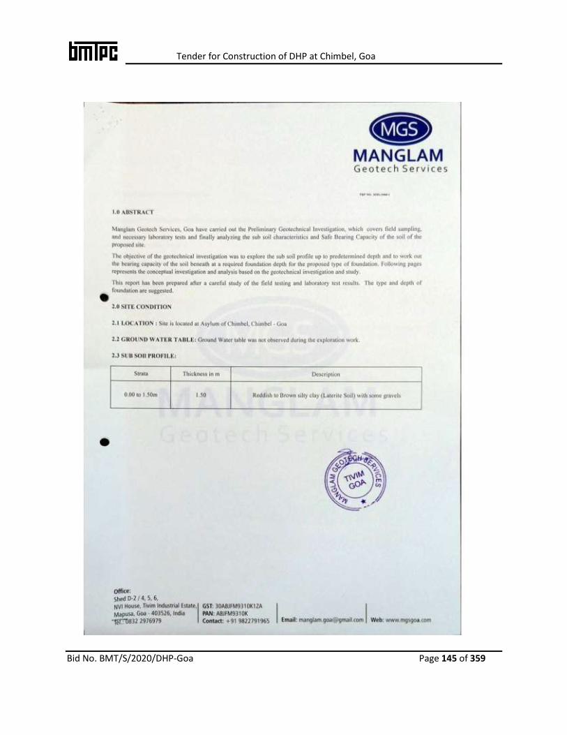
Tender for Construction of DHP at Chimbel, Goa
Bid No. BMT/S/2020/DHP-Goa Page 145 of 359

Tender for Construction of DHP at Chimbel, Goa
Bid No. BMT/S/2020/DHP-Goa Page 146 of 359
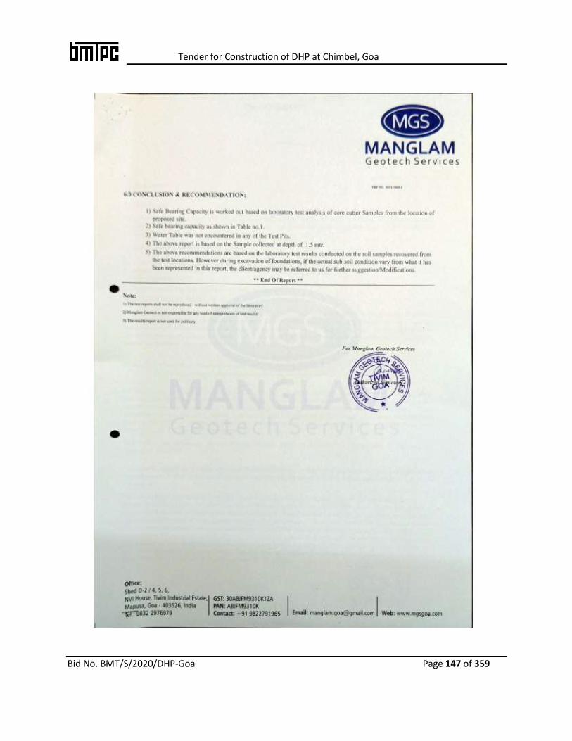
Tender for Construction of DHP at Chimbel, Goa
Bid No. BMT/S/2020/DHP-Goa Page 147 of 359

Tender for Construction of DHP at Chimbel, Goa
Bid No. BMT/S/2020/DHP-Goa Page 148 of 359

Tender for Construction of DHP at Chimbel, Goa
Bid No. BMT/S/2020/DHP-Goa Page 149 of 359
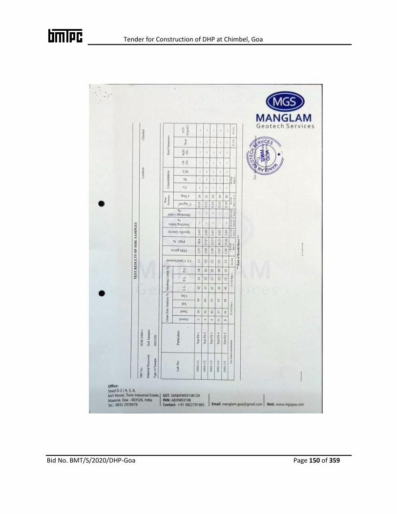
Tender for Construction of DHP at Chimbel, Goa
Bid No. BMT/S/2020/DHP-Goa Page 150 of 359
Tender for Construction of DHP at Chimbel, Goa
Bid No. BMT/S/2020/DHP-Goa Page 151 of 359
Part-7
Architectural Drawings
Tender for Construction of DHP at Chimbel, Goa
Bid No. BMT/S/2020/DHP-Goa Page 152 of 359
ARCHITECTURAL DRAWINGS
SL. NO TITLE
1. LAYOUT PLAN
2. GROUND FLOOR PLAN
3. TYPICAL FLOOR PLAN
4. TERRACE
5. ELEVATION
6. SECTION
7. SEWER LAYOUT PLAN
8. WATER SUPPLY LAYOUT PLAN
9. DRAINAGE LAYOUT PLAN
10. EXERNAL ELECTRICAL LAYOUT PLAN
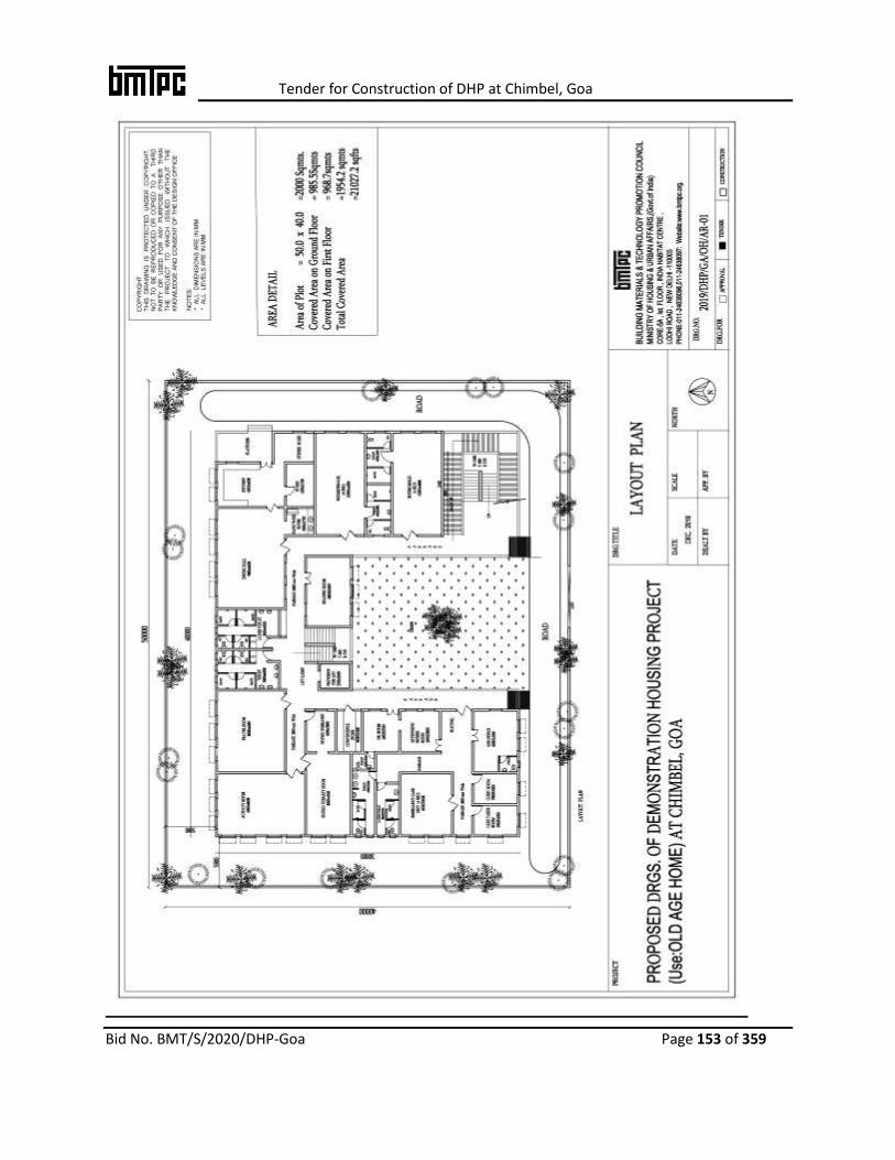
Tender for Construction of DHP at Chimbel, Goa
Bid No. BMT/S/2020/DHP-Goa Page 153 of 359

Tender for Construction of DHP at Chimbel, Goa
Bid No. BMT/S/2020/DHP-Goa Page 154 of 359
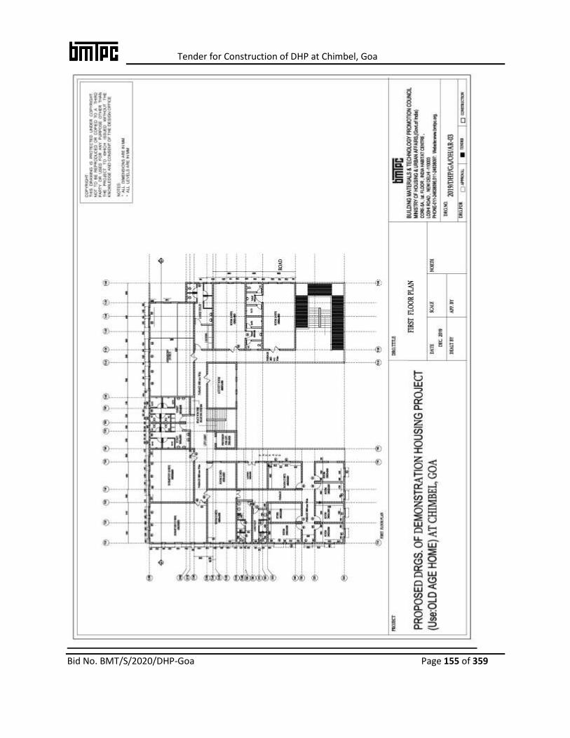
Tender for Construction of DHP at Chimbel, Goa
Bid No. BMT/S/2020/DHP-Goa Page 155 of 359
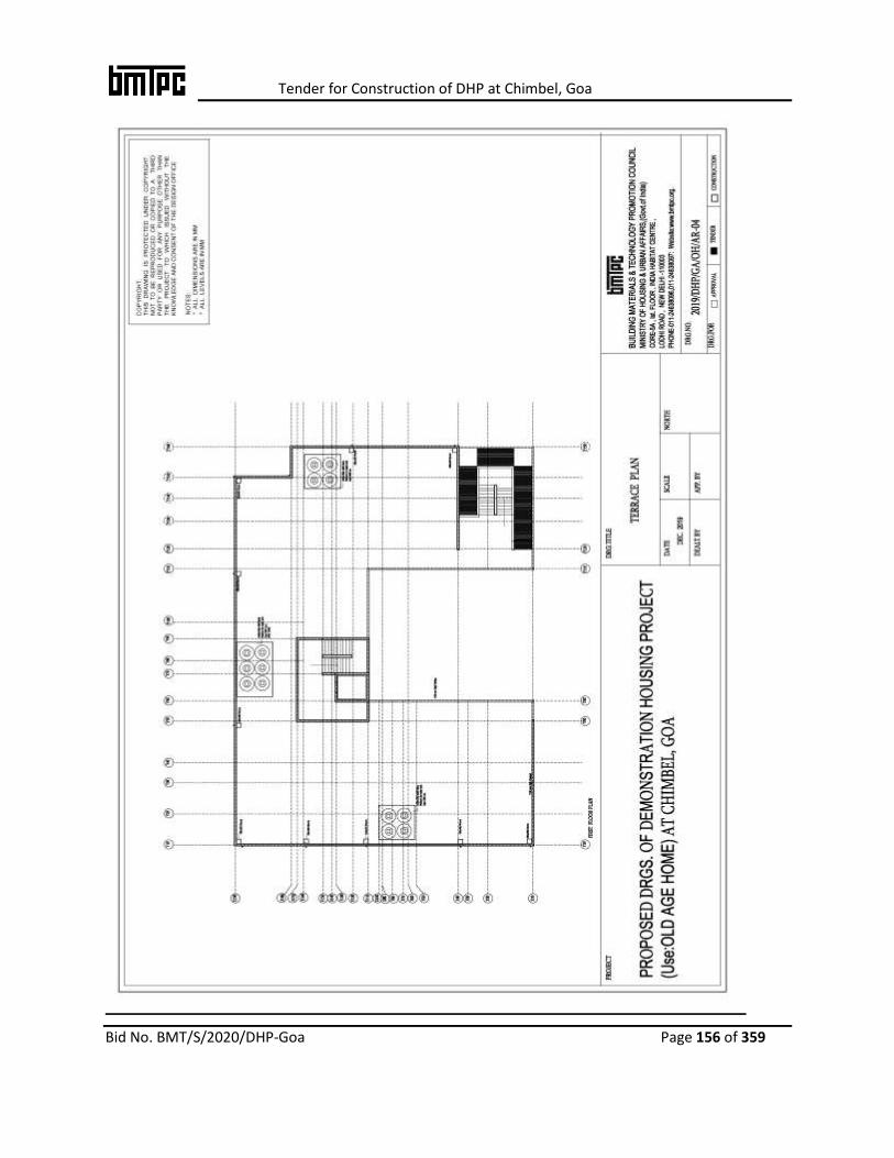
Tender for Construction of DHP at Chimbel, Goa
Bid No. BMT/S/2020/DHP-Goa Page 156 of 359

Tender for Construction of DHP at Chimbel, Goa
Bid No. BMT/S/2020/DHP-Goa Page 157 of 359

Tender for Construction of DHP at Chimbel, Goa
Bid No. BMT/S/2020/DHP-Goa Page 158 of 359

Tender for Construction of DHP at Chimbel, Goa
Bid No. BMT/S/2020/DHP-Goa Page 159 of 359

Tender for Construction of DHP at Chimbel, Goa
Bid No. BMT/S/2020/DHP-Goa Page 160 of 359

Tender for Construction of DHP at Chimbel, Goa
Bid No. BMT/S/2020/DHP-Goa Page 161 of 359

Tender for Construction of DHP at Chimbel, Goa
Bid No. BMT/S/2020/DHP-Goa Page 162 of 359
Tender for Construction of DHP at Chimbel, Goa
Bid No. BMT/S/2020/DHP-Goa Page 163 of 359
Part-8
Technical Specifications of
Emerging Technologies

Tender for Construction of DHP at Chimbel, Goa
Bid No. BMT/S/2020/DHP-Goa Page 164 of 359
DETAILS OF TECHNOLOGIES
CERTIFIED BY
BMTPC
UNDER PACS

Tender for Construction of DHP at Chimbel, Goa
Bid No. BMT/S/2020/DHP-Goa Page 165 of 359
1. Monolithic Concrete Construction System –using Aluminum/Plastic Formwork (WILL NOT BE CONSIDERED)
ABOUT THE TECHNOLOGY
The technology intents to replace the conventional steel/plywood shuttering (formwork) system
with customized engineered formwork which is manufactured in the factory setup under
controlled conditions. In this system, in place of traditional RCC framed construction of columns
and beams and infill walls; all floors, slabs, columns, beams, walls, stairs, together with door
and window openings are cast-in-place monolithically using appropriate grade of concrete in
one operation. The specially custom designed modular formwork made up of
Aluminium/Plastic/Aluminium Plastic Composite is used for the purpose which facilitates easy
handling with minimum labour& without use of any equipment. Being modular form work
system, it enable fast construction of multiple/mass modular units.
BASIC MATERIAL REQUIREMENTS
Formwork system
Formwork system is manufactured by various firms in India and abroad and shall have to be designed as per loading requirements of the structure. It must have adequate stiffness to weight ration, yielding minimum deflection during concreting & operation. The panel formwork should fix precisely, securely and require no bracing. Being recent advancement in technology ,IS14687:1999 Guideline for falsework for concrete does not cover requirements of special type of formwork system, however, it is being covered in NBC - 2016. Concrete
Shall be of appropriate grade based on environment
Condition (exposure) as per IS 456:2000.
Reinforcement Shall conform to IS 1786:2008.
DETAILS OF FORMWORK The formwork made of Aluminium Extruded Section conforming to IS 733:1983and PVC of Grade PVC67GER01is in accordance with IS 10151:1982.It consists of different sections including starter of MS Angle, top frame of aluminium channels, wall panels, slab panels & truss.The formwork is designed based on the structural requirements of building units. A quality control system is required to be followed in manufacturing of formwork components.
Tender for Construction of DHP at Chimbel, Goa
Bid No. BMT/S/2020/DHP-Goa Page 166 of 359
Under Performance Appraisal Certification Scheme, the present formwork system manufactured
by M/s Sintex Industries, Ahmedabad, has been evaluated and certified by BMTPC (PAC No.
1006-A/2011).
STRUCTURAL REQUIREMENTS OF THE CONSTRUCTION
The Monolithic RCC construction is considered as shear wall system. The maximum spacing
between crosswall shall be limited to1.5 times the floor height if supported on two edges and
2.0 times the floor height, when supported on all four edges.
The walls are designed primarily for vertical loading and also for in-plane lateral load (shear)
and out of plane (bending) due to wind load and earthquake forces as per relevant Indian
Standard Code IS 875(Pt.3):2015 and IS1893(Pt.1):2016 respectively. For out of plane loading,
the walls can be assumed to be supported by floor slabs / diaphragm and cross walls and
continuity can be assumed, wherever applicable.
The structural design of plain & RCC shall be as per IS456:2000 whileIS13920:2016 is referred
for ductile detailing of reinforced concrete structure. Thickness of wall be low plinth level should
be minimum 200 mm with double layer reinforcement.
Guidelines on Monolithic Concrete Construction prepared by BMTPC may be referred for
material requirements & design aspects of this system.
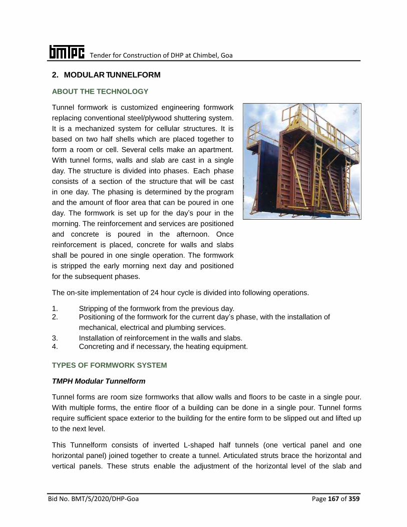
Tender for Construction of DHP at Chimbel, Goa
Bid No. BMT/S/2020/DHP-Goa Page 167 of 359
2. MODULAR TUNNELFORM ABOUT THE TECHNOLOGY
Tunnel formwork is customized engineering formwork
replacing conventional steel/plywood shuttering system.
It is a mechanized system for cellular structures. It is
based on two half shells which are placed together to
form a room or cell. Several cells make an apartment.
With tunnel forms, walls and slab are cast in a single
day. The structure is divided into phases. Each phase
consists of a section of the structure that will be cast
in one day. The phasing is determined by the program
and the amount of floor area that can be poured in one
day. The formwork is set up for the day’s pour in the
morning. The reinforcement and services are positioned
and concrete is poured in the afternoon. Once
reinforcement is placed, concrete for walls and slabs
shall be poured in one single operation. The formwork
is stripped the early morning next day and positioned
for the subsequent phases. The on-site implementation of 24 hour cycle is divided into following operations.
1. Stripping of the formwork from the previous day. 2. Positioning of the formwork for the current day’s phase, with the installation of
mechanical, electrical and plumbing services.
3. Installation of reinforcement in the walls and slabs. 4. Concreting and if necessary, the heating equipment.
TYPES OF FORMWORK SYSTEM
TMPH Modular Tunnelform
Tunnel forms are room size formworks that allow walls and floors to be caste in a single pour.
With multiple forms, the entire floor of a building can be done in a single pour. Tunnel forms
require sufficient space exterior to the building for the entire form to be slipped out and lifted up
to the next level. This Tunnelform consists of inverted L-shaped half tunnels (one vertical panel and one
horizontal panel) joined together to create a tunnel. Articulated struts brace the horizontal and
vertical panels. These struts enable the adjustment of the horizontal level of the slab and

Tender for Construction of DHP at Chimbel, Goa
Bid No. BMT/S/2020/DHP-Goa Page 168 of 359
simplify the stripping of the formwork. The vertical panel is equipped with adjustable jacking
devices and a triangular stability system. Both devices are on wheels. A range of spans is possible by altering the additional horizontal infill panel’s dimensions. Due
to the distribution of the horizontal beams on the vertical plank, the formwork also cast staggers
and offsets in the layout of the walls as well as differing wall thicknesses. The half-tunnels shall
be equipped with back panels to cast perpendicular shear walls or corridor walls. Assembly
and levelling devices ensure that the frormwork surfaces are completely plumbed and levelled.
Standard Characteristics
Standard dimensions: TMPH & Modular
Unit width : 2.40 m to 6.00 m
Type 1 horizontal panel :
1.20 m to 1.60 m
Type 2 horizontal panel:
1.80 m to 2.40 m
Type 3 horizontal panel:
2.40 m to 3.00 m
The span can be adjusted by fitting an additional panel measuring between 0.05 and 0.60 m
Package length: Up to 12.50 m in length as a function of the hoisting facilities and availability
Basic length: 1.25 m
Average weight: 90 Kg/m2
Handling: Lifting triangle or sling
Transportation: 180 m2 per truckload.
Wallforms Wallforms are temporary moulds in which concrete is
poured in order to build a structure. Once the concrete is
poured into the formwork and has set, the formwork is
stripped to expose perfect finished concrete. These forms
constitute a system approach for construction and are
particularly suited to build structural walls, columns,
bridge piers, culverts etc. This system adopts well to
daily work-phase of both repetitive and non-repetitive
tasks. The equipment used each day is productive and is
reused in subsequent phases. The four daily operations
Tender for Construction of DHP at Chimbel, Goa
Bid No. BMT/S/2020/DHP-Goa Page 169 of 359
which outlines the daily production cycle for wall form equipment are identical to those for Tunnel
form equipment with the exception that it is solely used for casting concrete walls. The slabs are
cast as a secondary phase. The existing equipment can be adapted on a day-to-day basis by the
addition of standard elements and corner-wall formwork to take into account different wall
configurations on site. All safety and stability devices shall be fully integrated into the standard
version of Wallform equipment.
B 8000 Wallforms
These Wallforms are tools specially designed to be used on specific buildings and structures.
This vertical wallform panel is a multi-purpose formwork system. This system has been designed
and developed to ensure that it is simple and quick to assemble and position the following:
A full range of standard dimensioned components
Multiple combination of panels for simple adoption to specific configurations
Basic standard equipment incorporates complete safety, circulation and stability equipment
Caliper–device opposing Wallform packages are craned into position in one lift.
Standard characteristics Standard dimensions:
Standard height : 2.80 m
Upper extension : 0.50 m
Lower extension : 1.00 m-1.50 m
Average weight : 135 Kg/m2
Assembly : 0.80 H/m2 of formwork
Use : 0.15 to 0.30 H/m2 of formwork, depending on complexity
Wind stability : by prop
Access : inner ladder accessed via hatch
Superposition : up to 22.5 m with specific engineering performed to determine hoisting and stability characteristics
Transportation: 24 wall forms per container/ truckload Angle Formwork
Inner and outer angle configurations are designed to attach to 1.25 m wall forms to obtain a 160 mm wall. Spacers shall be installed for producing wall thicknesses.
Back Panel
The back panel allows pouring of cross walls, other walls, walls and slab in one operation. Slab Stop End and Wall stop
These can be adjusted to fit the lengths of wall and slabs. These remain fixed to the form during
all handling operations.
Tender for Construction of DHP at Chimbel, Goa
Bid No. BMT/S/2020/DHP-Goa Page 170 of 359
Kicker Form
In order to guide the walls of the upper floor precisely above the walls of the floor below, a kicker form is fixed to the
tunnel form before pouring the concrete. Slab and starting walls are then poured during the same phase.
Box Out
During each phase, window box out, door box out and slab box out are mounted on the tunnel
using a magnetized system.
MATERIAL REQUIREMENTS
i. Hot dip galvanized steel sheet – 3 mm thick shall conform to IS 277:2003 ii. Steel for Angle section – 80 mm x 80 mm x 6 mm shall conform to IS 2062:2011 .
iii. Cold rolled U-sections – 60 mm x 30 mm shall conform to IS 2062:2011.
Mechanical properties:
Yield stress : ≥ 23.5 daN/mm2
Breaking load : ≥ 36 daN/mm2
Elongation : ≥ 20%
Steel for spacer pins – Apart from the requirements given above, the steel used for the
manufacture of the spacer pins, the gripping mechanisms, anchoring points for the rear
stabilizing and adjusting mechanisms shall guarantee a KCV resilience at –20ºC of at least
28J.
CHARACTERISTICS OF THE SYSTEM
Maximum span between walls shall be 5.60 m without accessory units and 7.00 m with accessory units.
Height of the formwork – The forms are designed for floor to ceiling height of 2.51 m minimum with the possibility to increase this by action of the leg jacks or with the use of movable panels in the event of extra heights.
Appearances of the faces after form removal – The surfaces obtained allow direct application of finishing paint or wallpaper after sanding off the fins at the joints connecting the units and smoothing with paint filler.
Working rhythm using the system – Under average temperature conditions, with the use of ordinary cement,
the normal rhythm is two days per cycle with one day and two nights for drying and setting of the concrete.
Time period required for execution of the process – The time required for execution shall vary according to the cell plan. For a type cell consisting of two formed wall surfaces and a floor surface, the average time is less than one & one half hours per square meter of building. This time includes the form removal, oiling, displacement of the units, formwork and adjustment.
UTILIZATION OF THE FORMWORK SYSTEM
Tender for Construction of DHP at Chimbel, Goa
Bid No. BMT/S/2020/DHP-Goa Page 171 of 359
At each stage, utilization of the system requires the following successive operations:
i. The placing of the vertical wall reinforcement of the floor and possibly the door frames provided for in the erection drawing;
ii. Dismantling of the movable form units of the preceding storey. This shall be carried out in two stages:
a) Loosening of the normal units (half-shells), by removal of the spacers passing through the walls, by unlocking the tunnel keys and disassembly of the sections. This work is executed in principle by two non-specializes maneuvers.
b) Striking and removal of the forms. This shall be carried out by using the special dolly and two maneuvers in the tunnel and by two other maneuvers at the new location (usually on the storey above). This suite of operations shall be carried out by bringing the dolly under the half-shell to be removed and then working the different jacks for the striking operation itself. The leg jacks are lifted first, then a slight deformation of the half-shell is provoked by working the diagonal bracing jacks (shortening). This deformation is sufficient to strip the form progressively. It drops down automatically onto the dolly. The dolly half-shell assembly shall then be rolled across the service platform where the form is cleaned and oiled with a sprayer, then picked up with a crane and hoisted to its new location site, the dolly remaining in place. The half-shell design makes it possible to remove the whole side of a tunnel, then to prop the slab near the key before removing the other half, permitting if necessary, a faster rotation of the equipment.
iii. Reassembly of the units on the floor above. This assembly consists of the following operations: a. A half-shell shall be positioned on its leg jacks and knee brace, and adjustment shall
be squared by blocking the diagonal bracing jacks, then adjustment of the height and plumb by working the leg jacks and the knee brace jack.
b. The half-shells shall be assembled together. c. The opposite half-shells shall be positioned, and adjacent half-shells of the ‘tunnel’
half-shells shall also be positioned using the same procedure. d. The half-shells shall be blocked by constituting the two faces of the wall on the
‘starters’ with the help of the lower spacers; the upper spacers shall be tightened without being forced, only after verification of the general adjustment; positioning of the butt end forms of the walls and floors.
e. The key-locks solidifying the opposite half-shells shall be positioned and blocked. If necessary, a light action on the knee brace and diagonal bracing jacks shall be used to bring the locking units into line.
f. The starter forms shall be positioned and blockouts, if necessary for anticipated door and window frames.
g. The overall adjustment and finish making–up shall be verified, if necessary, after lifting of the knee braces.
h. The suspended floor shall be reinforced and concrete shall be poured in the walls and slab.
iv. The service platform shall be removed and this platform shall be installed on the storey above.

Tender for Construction of DHP at Chimbel, Goa
Bid No. BMT/S/2020/DHP-Goa Page 172 of 359
3. INSULATING CONCRETE FORMS & 4. MONOLITHIC INSULATING CONCRETE FORMS Insulating concrete Forms (ICF) System comprises of a panel of two walls of Expandable Polystyrene (EPS) separated by a nominal distance of 150mm by hard plastic ties. These are assembled on site to hold reinforced concrete. The forms are open ended hollow polystyrene blocks which fit tightly together to form a shuttering system. Concrete poured into the hollow space to form a continuous wall. When cured, this wall supports the structural loads from f loors and roofs, and the shuttering provides thermal insulation. Reinforcing steel shall be as required as per the design parameters. Upper and lower surfaces of the polystyrene panels are castellated and the vertical mating surfaces are tongue-and-groove to form a tight fit when joined together. The rigid formwork does not require supporting falsework. Form locks are used for end stops. The outer surfaces are grooved vertically at 50 mm centres to aid cutting and trimming. Plan view of ICF is shown in Fig. 1.
Fig. 1 Types of Forms Standard Forms – These form bulk of the forms and have 50mm EPS panels on both sides with hard plastic ties holding the panels. Dimensions of these forms are 1000 x 250 x 250mm. (See Fig. 2) Lintel Forms - In combination with Half Height forms, these form the top layer of all wall gaps and hold the concrete thus preventing thermal leaks. Dimensions of these forms are 1000 x 125 x 250mm. (See Fig. 3) Half Height Forms –Together with the lintel, these form the top layer of all gaps in

Tender for Construction of DHP at Chimbel, Goa
Bid No. BMT/S/2020/DHP-Goa Page 173 of 359
the wall and hold the required steel reinforcement. Dimensions of these forms are 1000 x 150 x 250mm. (See Fig. 4) Floor Edge Forms – These form the top most layer, where the wall ends and floor begins. This envelopes the floor slab and thus prevents thermal bridging. Dimensions of these forms are 1000 x 375/125 x 250mm. (See Fig. 5) Corner Forms – These constitute 90º corner of the building. The two sides are 50mm EPS panels held together with 8 hard ties. Dimensions of these forms are 750/500 x 250 x 250mm. (See Fig. 6) End Forms – These create wall ending by fitting in inside the Standard or Corner form and provide a smooth and thermal bridge ending to the wall.
Dimensions of these forms are 150 x 125 x 50mm. (See Fig. 7) Fig. 2 Standard Fig. 3 Lintel Fig. 4 Half Height
Fig. 5 Floor Edge Fig. 6 Corner Fig. 7 End
Specification of Raw materials:
i. Expanded Polystyrene (EPS): Self-extinguishing type EPS shall conform to IS 4671: 1984 having density not less than 25 kg/m3 and valid Restriction of Hazardous Substance (ROHS) test certification.
ii. Polyurethane (PU) Foam Adhesive: Shall have Skin Formation of 8 min, Density 25 kg/m³, Sound insulation 58 dB, Insulation factor 35 mW/mK, Shrinkage< 2%,
Fire rating B3, Insulation factor 35 mW/m.K and Water absorption of 1 % volume.

Tender for Construction of DHP at Chimbel, Goa
Bid No. BMT/S/2020/DHP-Goa Page 174 of 359
iii. Plasticizer: Slump retaining super plasticizer for self -compacting plastic concrete (CEMWET SP-3000) shall conform to IS 9103:1999
iv. Hard Plastic Tie: Shall be made with HDPE v. Cast-in-place concrete: The ingredients, grade of concrete &
slump for walls, floors and roofs shall be used as per IS 456:2000. Typical Construction Construction process The construction of most Insulating Concrete Forms (ICF) buildings is fundamentally & Monolithic a process of stacking lightweight blocks together in a similar manner to building bricks, laying reinforcement where necessary and pouring concrete into the voids of the block work. Footings The footings for Insulating Concrete Forms (ICF) buildings shall be reinforced concrete rafts or strips that are flat and even enough to enable stacking of the form blocks, with reinforcement starter bars set ready to connect with the concrete when poured into the formwork. Load bearing walls Any Insulated Concrete bearing System/Forms wall can be designed to be load Joints and connections Joints and connections with other building elements shall be kept to a minimum, especially when the flooring or roofing elements are also made from Insulated Concrete System/Forms. Fixings The foam block work or form work forms a poor basis for any fixings. Light loads are generally carried by the lining or facing materials, such as plaster board, and heavier loads can be carried by supporting points drilled in to the concrete that forms the inner material of the Insulated Concrete System/Forms. Openings Major openings for doors, windows, etc., shall be set out in the form work as it is relatively difficult to make changes later, owing to the fundamentally monolithic nature of the structural elements. Once openings have been made, they can accommodate window and door frames of any type. A typical kind of fixing uses timber blocks set in to the ends of the form blocks around the opening. Electrical conduit and plumbing is generally run in chasing in the depth of the form blocks.
Tender for Construction of DHP at Chimbel, Goa
Bid No. BMT/S/2020/DHP-Goa Page 175 of 359
Finishes Finishes are dependent on the materials used to face the Insulated Concrete System/Forms units. Typically, the main finish is a render o r render- equivalent covering or paint. Any additional cladding can be added to the Insulating Concrete Forms (ICF) walls subject to making appropriate sup- ports for it, although many sheet finishes, such as plaster board, can be glued directly to the surface of the formwork. External renders require a base or skim coat embedded with fiber glass mesh, followed by a second coat and then a texture coating, finally finished with an ‘armor coat’. Structural Aspects The Insulating Concrete Forms (ICF) may be designed using the appropriate design software. The buildings constructed with EPS shall be designed as reinforced concrete structure since the parameters required for their design are the same as needed for traditional reinforced concrete. In the calculation model, the building shall be designed in accordance with IS 456:2000, as applicable, as structure composed of load bearing walls with a box-like structure. The system shall be designed to provide the required performance against the loads to be taken into account in accordance with IS 875 (Parts 1,2,4&5):1987. It shall also provide the required bearing resistance for earthquake and wind forces as per IS 875 (Part 3):2015 and IS 1893(Part1):2016, wherever applicable. All relevant Indian Standards/ requirement of NBC shall be conformed.

Tender for Construction of DHP at Chimbel, Goa
Bid No. BMT/S/2020/DHP-Goa Page 176 of 359
5. STAY-IN-PLACE FORMWORK SYSTEM (WILL NOT BE CONSIDERED)
Brief Discription The formwork system comprises of two filtering grids made of rib mesh reinforced by ‘C’
channel vertical stiffeners. The grids are connected by rebar which act as horizontal stiffeners
and connector which act as a shear link. The grids on both faces act as sacrificial formwork in
which concrete is poured in-situ. The vertical steel channels and horizontal steel bars act as
steel reinforcement for load bearing wall. The connectors help to fold the formwork for easy
transportation.
After the erection of formwork panels in alignment, corners, edges of doors and windows frame
are closed with rebar positioning & concrete of required grade is poured in the panels. The
concreting may be done with a pump, bucket or with a shovel loader. The inside and outside
walls are finished with cement plaster of suitable grade.
The panels are prefabricated according to a structural plan (based on client’s architectural
plans) designed by structural engineers.
Product assembly Components in Structural Stay-in-Place Formwork Panel:
The various parts of Structural Stay-in-Place Formwork panel are explained briefly below:
Part – 1: C-Chanel
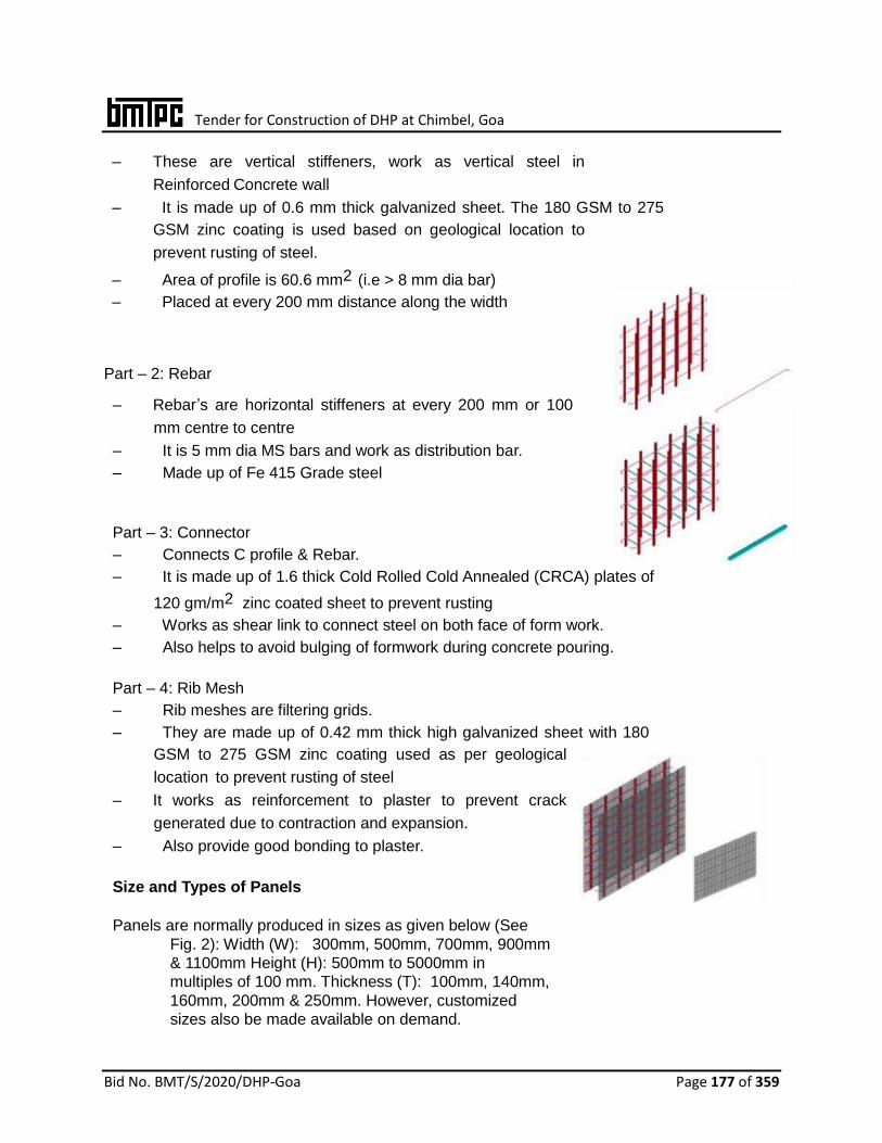
Tender for Construction of DHP at Chimbel, Goa
Bid No. BMT/S/2020/DHP-Goa Page 177 of 359
– These are vertical stiffeners, work as vertical steel in
Reinforced Concrete wall
– It is made up of 0.6 mm thick galvanized sheet. The 180 GSM to 275
GSM zinc coating is used based on geological location to
prevent rusting of steel.
– Area of profile is 60.6 mm2 (i.e > 8 mm dia bar)
– Placed at every 200 mm distance along the width
Part – 2: Rebar
– Rebar’s are horizontal stiffeners at every 200 mm or 100
mm centre to centre
– It is 5 mm dia MS bars and work as distribution bar.
– Made up of Fe 415 Grade steel Part – 3: Connector
– Connects C profile & Rebar.
– It is made up of 1.6 thick Cold Rolled Cold Annealed (CRCA) plates of
120 gm/m2 zinc coated sheet to prevent rusting
– Works as shear link to connect steel on both face of form work.
– Also helps to avoid bulging of formwork during concrete pouring. Part – 4: Rib Mesh
– Rib meshes are filtering grids.
– They are made up of 0.42 mm thick high galvanized sheet with 180
GSM to 275 GSM zinc coating used as per geological
location to prevent rusting of steel
– It works as reinforcement to plaster to prevent crack
generated due to contraction and expansion.
– Also provide good bonding to plaster. Size and Types of Panels
Panels are normally produced in sizes as given below (See
Fig. 2): Width (W): 300mm, 500mm, 700mm, 900mm
& 1100mm Height (H): 500mm to 5000mm in
multiples of 100 mm. Thickness (T): 100mm, 140mm,
160mm, 200mm & 250mm. However, customized
sizes also be made available on demand.

Tender for Construction of DHP at Chimbel, Goa
Bid No. BMT/S/2020/DHP-Goa Page 178 of 359
Panel
Type T
mm A
mm B
mm W
mm H
mm C10 100 200 100, 200 300,
500,
700,
900,
1100
Min.
500
then
in multiples
of 100
C14 140 200 100, 200 C16 160 200 100, 200 C20 200 200 100, 200 C25 250 200 100, 200
Fig.2
Types of panels are given below:
i. Standard single panels – These panels shall be used for slab shuttering but may also be
used as shuttering option for RCC wall having thickness of more than 350mm. (Fig. 3)
ii. Double panels – Double panels shall have inbuilt steel and not require extra reinforcement.
In double panels, the grids shall be connected by articulated rebar loops and connectors
that fold.
These panels are of two types:
(a) Standard double panels shall be of fixed size and need to be cut on site for openings etc.
(b) Customized double panels from the factory shall have required cutting for openings
as per drawing and there is no need for cutting on site.
(c) These panels create a monolithic structure as it allows pouring of walls and
slab together. These panels shall be used for load bearing walls, retaining walls
and shear walls. (Fig. 4)
iii. Insulated Double panel – These panels shall have an integrated insulation on the exterior
side. The insulated material shall be of polystyrene or polyurethane of required thickness
as per design.(Fig. 5)
iv. Fiber Cement Double panel – These panels shall have its interior face as fibre cement board which has smooth surface and avoid plastering of walls. (Fig. 6). These panels may be used for water retaining structures.
Fig.3 Standard Single Panel Fig.4 Standard Double Panel
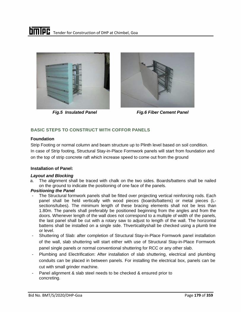
Tender for Construction of DHP at Chimbel, Goa
Bid No. BMT/S/2020/DHP-Goa Page 179 of 359
Fig.5 Insulated Panel Fig.6 Fiber Cement Panel
BASIC STEPS TO CONSTRUCT WITH COFFOR PANELS Foundation
Strip Footing or normal column and beam structure up to Plinth level based on soil condition.
In case of Strip footing, Structural Stay-in-Place Formwork panels will start from foundation and
on the top of strip concrete raft which increase speed to come out from the ground
Installation of Panel:
Layout and Blocking a. The alignment shall be traced with chalk on the two sides. Boards/battens shall be nailed
on the ground to indicate the positioning of one face of the panels. Positioning the Panel - The Structural formwork panels shall be fitted over projecting vertical reinforcing rods. Each
panel shall be held vertically with wood pieces (boards/battens) or metal pieces (L-sections/tubes). The minimum length of these bracing elements shall not be less than 1.80m. The panels shall preferably be positioned beginning from the angles and from the doors. Whenever length of the wall does not correspond to a multiple of width of the panels, the last panel shall be cut with a rotary saw to adjust to length of the wall. The horizontal battens shall be installed on a single side. Thverticalityshall be checked using a plumb line or level.
- Shuttering of Slab: after completion of Structural Stay-in-Place Formwork panel installation
of the wall, slab shuttering will start either with use of Structural Stay-in-Place Formwork
panel single panels or normal conventional shuttering for RCC or any other slab.
- Plumbing and Electrification: After installation of slab shuttering, electrical and plumbing
conduits can be placed in between panels. For installing the electrical box, panels can be
cut with small grinder machine.
- Panel alignment & slab steel needs to be checked & ensured prior to concreting.

Tender for Construction of DHP at Chimbel, Goa
Bid No. BMT/S/2020/DHP-Goa Page 180 of 359
- Concrete Pouring: The placing of concrete of specified grade is done in wall and slab in
one go with either with Boom placer, stationary pump or manually. As all concreting is
done in one go, a monolithic reinforced concrete structure is created.
STRUCTURAL REQUIREMENTS OF THE CONSTRUCTION
The design strategy is to utilize concrete and formwork steel to the ultimate and to provide
standard solutions for minimum reinforcement to be used, wherever required, depending on the
application and will be determined by structural calculations performed according to the IS
456:2000. In seismic prone areas requiring seismic resistant construction, relevant provisions
of IS 875 (Part 1, 2, 4 & 5):1987, IS 875 (Part 3):2015, IS 1893 (Part 1):2016, IS 4326:2013
and IS 13920:2016 shall apply. Design analysis of the Structural formwork walls, panels, floor slabs etc. shall be done using
Staad Pro Software or equivalent. The Optimal result is obtained when walls shall be designed
as braced construction elements whose horizontal loads are supported by other bracing
elements belonging to the same construction e.g. shear walls. The panels with concrete shall
act as “lightly reinforced RCC walls” as per clause 32 of IS 456:2000 and as “prefabricated
concrete load bearing walls” as per IS 15916:2010 & IS 15917:2010 & amp; IS 15971:2010.
The Structural Form work vertical reinforcement shall act as 8mm dia. and horizontal mild steel
bar of 8mm dia. shall act as distribution steel, shall be taken for design as per National Building
Code of India.
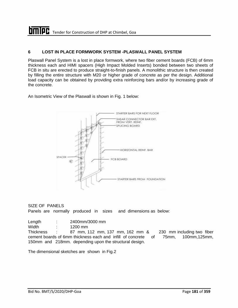
Tender for Construction of DHP at Chimbel, Goa
Bid No. BMT/S/2020/DHP-Goa Page 181 of 359
6 LOST IN PLACE FORMWORK SYSTEM -PLASWALL PANEL SYSTEM
Plaswall Panel System is a lost in place formwork, where two fiber cement boards (FCB) of 6mm thickness each and HIMI spacers (High Impact Molded Inserts) bonded between two sheets of FCB in situ are erected to produce straight-to-finish panels. A monolithic structure is then created by filling the entire structure with M20 or higher grade of concrete as per the design. Additional load capacity can be obtained by providing extra reinforcing bars and/or by increasing grade of the concrete.
An Isometric View of the Plaswall is shown in Fig. 1 below:
SIZE OF PANELS
Panels are normally produced in sizes and dimensions as below:
Length : 2400mm/3000 mm
Width : 1200 mm
Thickness : 87 mm, 112 mm, 137 mm, 162 mm & 230 mm including two fiber cement boards of 6mm thickness each and infill of concrete of 75mm, 100mm,125mm, 150mm and 218mm. depending upon the structural design. The dimensional sketches are shown in Fig.2
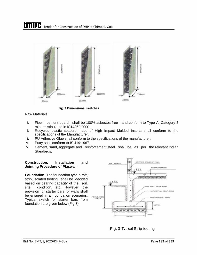
Tender for Construction of DHP at Chimbel, Goa
Bid No. BMT/S/2020/DHP-Goa Page 182 of 359
Raw Materials
i. Fiber cement board shall be 100% asbestos free and conform to Type A, Category 3
min. as stipulated in IS14862:2000. ii. Recycled plastic spacers made of High Impact Molded Inserts shall conform to the
specifications of the Manufacturer.
iii. PU Adhesive Glue shall conform to the specifications of the manufacturer.
iv. Putty shall conform to IS 419:1967.
v. Cement, sand, aggregate and reinforcement steel shall be as per the relevant Indian
Standards.
Construction, Installation and Jointing Procedure of Plaswall
Foundation The foundation type a raft, strip, isolated footing shall be decided based on bearing capacity of the soil, site condition, etc. However, the provision for starter bars for walls shall be ensured in all foundation scenarios. Typical sketch for starter bars from foundation are given below (Fig.3).
Fig. 3 Typical Strip footing
Fig. 2 Dimensional sketches

Tender for Construction of DHP at Chimbel, Goa
Bid No. BMT/S/2020/DHP-Goa Page 183 of 359
Panel Installation
Installation
The panel shall be lifted slightly and then placed along the bottom angles. The panel shall be plumbed at edge and face sides with provision of shims, if needed. The panel shall be screwed both sides at bottom at 250 mm center to center, while glue is applied & tacky. If glue is not available, spacing shall be kept at 200mm center to center. Support the temporarily angle installed on other side of panel to hold it in position for concreting (Fig. 4) Corner connection details shall be followed as shown in Fig. 5.
Fig. 4 Diagonal bracing Fig. 5 Corner connection
T-Section
After installing the primary walls, mark the place where corner will be constructed.
The joiner stud shall be placed and marked by pencil to have a vertical line reference.
The joiner stud shall be moved up by 60mm from slab to bottom of joiner stud. The stud hole shall be marked by pencil.
The marked slots shall be cut by 100mm angle grinder with dry type diamond blade.
Reinforced dowels shall be prepared, inserted & tied just after screwing the joiner stud corner connection. (Fig 5)
In case, the holes intersect with panel stud of the primary wall, the portion of primary stud shall be cut to accommodate the marked holes for T-connection. One 12mm vertical bar shall be provided as replacement.
In case of cross-connection, horizontal bars shall be provided.
Nib End Wall Detail
• For nib, end cap shall be provided. • Glue shall be applied on end cap stud which shall be inserted to correct
position and screwed.
Tender for Construction of DHP at Chimbel, Goa
Bid No. BMT/S/2020/DHP-Goa Page 184 of 359
Door & Window Jambs Installation
• Light gauge door & window jambs shall be provided for the panels Door jambs shall be
installed along with the panel. • Window jambs shall be installed (not fixed) as shown in Fig. 7 of Annex 4 to
accommodate concrete at window sills. This will eliminate honey-comb and ease pouring of concrete.
• The window sill shall be overflowed by concrete and then push down window frame. • The lintel panel shall be screwed to press down the window frame. Spacing of screws
shall be the same.
Embedment of Services
After installation of the panels, electrical and plumbing pipes shall be inserted into the panel as per the drawings.
Placing of Reinforcement Placing of reinforcement of required grade shall be as per the structural drawings and IS 456:2000 and IS 1139:1966. Concreting After placing of reinforcement and services in the panel, design grade / mix of concrete shall be poured by manually or by Pumping system. The concrete shall be poured from top of the wall or by cutting slit and attaching chute in the panel. Mix shall be prepared in accordance with section 9.2 of IS 456:2000 Aggregate of max. size 6 to 10mm shall be used. Slump should be between 175mm to 200mm.

Tender for Construction of DHP at Chimbel, Goa
Bid No. BMT/S/2020/DHP-Goa Page 185 of 359
Pouring of concrete
• After proper mixing of concrete as per the mix, concrete shall be poured manually into the panel from top of the wall or by cutting slit and attaching chute in the panel. The first pour of concrete should be of 300mm height and after setting, concrete shall be poured up to 800mm as above.
• After setting time of each pour of concrete, keep pouring upto 800mm height and continue
till height of the wall. • Above process shall be followed horizontally for different walls. This will allow setting time
of concrete for the previous wall while the next wall is being poured. • Setting time of concrete shall be min. three hours but during that time other walls shall be
poured. Since the project quantum will be big, there will be enough walls available to pour. • Rubber mallet shall be used for tapping the wall while pouring the concrete to avoid honey
comb/segregation.
Joint Treatment
After walls are completely filled and mix dried, joint treatment shall be done
using fiber mesh tape and putty.
Fig.8 Yellow Putty with Fiber mesh tape Fig.9 Joint Treatment
Construction of Slab
Once construction of panels is completed, slab construction shall be done as per the structural drawings with wall reinforcement and connection with slab reinforcement.
All relevant Indian Standards/ requirement of NBC shall be conformed.

Tender for Construction of DHP at Chimbel, Goa
Bid No. BMT/S/2020/DHP-Goa Page 186 of 359
7. LOST-IN-PLACE FORMWORK SYSTEM – PLASMOLITE WALL PANEL Plasmolite Panels are lost in place formwork system comprising of two fibre cement boards (FCB) of 6 mm thickness and High Impact Molded Inserts (HIMI) bonded between two sheets which also acts as spacers. The panel is erected to produce straight to finish walls which are filled with light weight foam concrete. The system may be integrated with conventional column and beam and also with pre-engineered buildings. The panels may be used as non load bearing walls for external and internal applications.
Fig. 1 Isometric View of Plasmolite Panel
Size of Panels Size: Panels are normally produced in sizes and dimensions as given below: Length: 2400/3000 mm Width: 1200 mm Thickness: 87 mm, 112 mm, 137 mm, 162 mm & 230 mm including two fibre cement
boards of 6mm thickness each. Typical dimensional diagrams are shown in Fig. 2.
Fig.2 Dimensional Diagrams

Tender for Construction of DHP at Chimbel, Goa
Bid No. BMT/S/2020/DHP-Goa Page 187 of 359
Raw Materials
Fibre cement board shall be 100% asbestos free and conform to Type A, Category 3 min. as stipulated in IS 14862:2000.
Recycled plastic spacers made of High Impact Molded Inserts shall conform to the specifications of the manufacturer.
PU Adhesive Glue shall conform to the specifications of the manufacturer.
Foaming agent shall conform to the specifications of the manufacturer.
Putty shall conform to IS 419:1967.
Cement, sand, aggregate and reinforcement steel shall be as per the relevant Indian Standards.
Panel Fabrication
After cutting fibre cement sheet to the desired dimensions, the edge of the sheet shall be recessed using recessing machine. Using the panel jig, one fibre cement sheet 6mm thick shall be placed on top of jig with the smooth face touching the jig flat form. Desired number of HIMI spacers shall be placed on top of fibre cement sheet and PU adhesive applied on the stud flanges (32 pieces for full panel 1200mm x 2400mm). HIMI spacers shall be aligned using pattern board. Another 6mm thick fibre cement sheet shall be placed on top of the studs to close the first panel. The same process as above shall be repeated until jig is filled with panels. Flat plywood covers shall be laid to compress the panel for 4 to 5 hours.
Panel Installation Surface of beams, columns and slab shall be dowelled by drilling holes and grouting it by using epoxy resins in the holes. Spacing between dowels shall be 300 mm as per design.
Installation
The panel shall be lifted slightly and then placed along the bottom angles. The panel shall be plumbed at edge and face sides with provision of shims, if needed. It is essential that panels be first installed starting from face of supporting column. The panel shall be screwed both sides at bottom keeping the spacing as / design, while glue is applied & Stacy. If glue is not available, spacing shall be kept at 200mm center to center. Support the temporarily angle installed on other side of panel to hold it in position for concreting Joints between two panels shall be fixed by using FCB strips 50 mm wide inside the panel with help of glue, screws and tacking pins. After installation of panel, electrical and plumbing pipes shall be inserted into the panel as per the drawings. Concrete mix Plasmolite foam generator and mixer shall be used for this purpose. An elaborated mix of cement, sand/fly ash and water shall be prepared, quantities of which vary depending upon required density and strength of foam concrete. Concrete can be poured in the panel by pumping or manually directly from top or intermediate position depending on floor to floor height and site conditions.
After walls are completely filled and mix dried, joint treatment shall be done using fibre mesh tape and putty. Mesh tape shall be sandwiched between first & second coats to have a hold over the wall. Wall is now ready to accept primer & paint.
All relevant Indian Standards/ requirement of NBC shall be conformed.
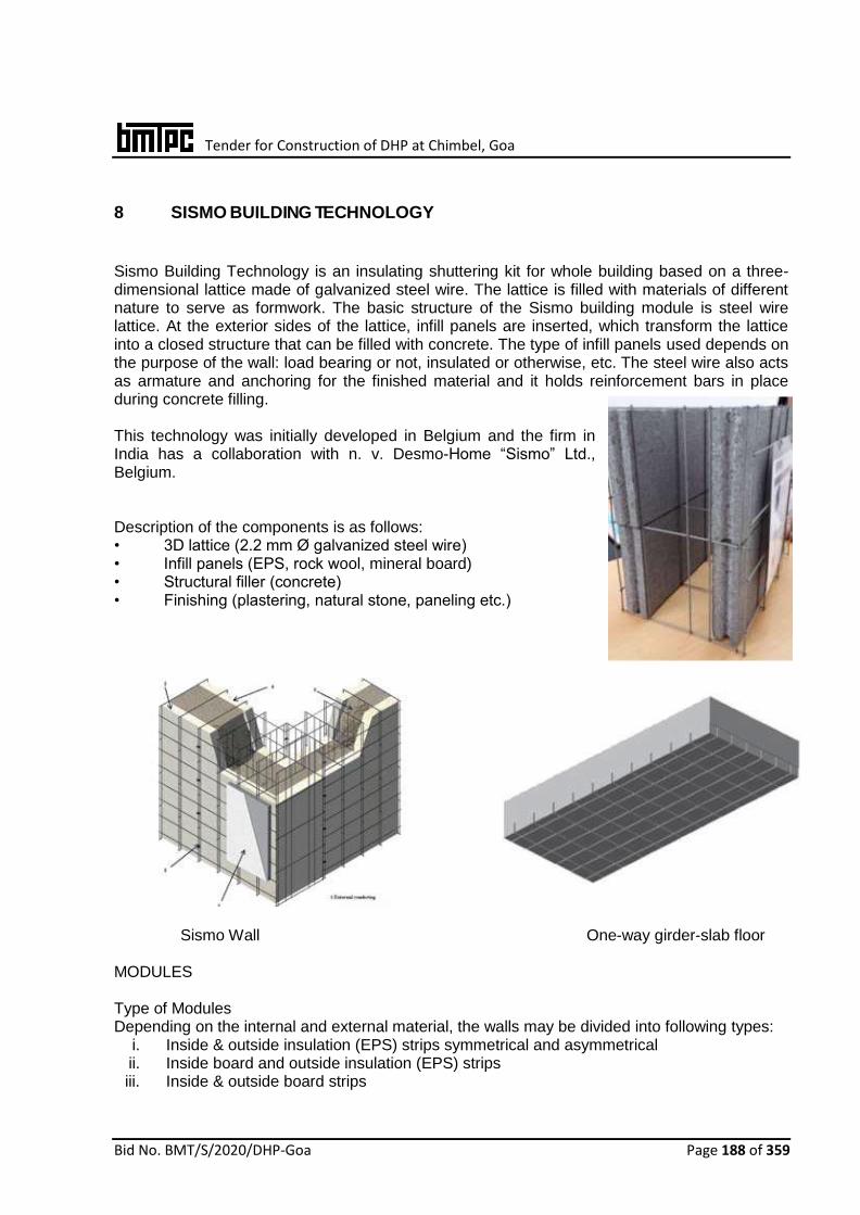
Tender for Construction of DHP at Chimbel, Goa
Bid No. BMT/S/2020/DHP-Goa Page 188 of 359
8 SISMO BUILDING TECHNOLOGY
Sismo Building Technology is an insulating shuttering kit for whole building based on a three-dimensional lattice made of galvanized steel wire. The lattice is filled with materials of different nature to serve as formwork. The basic structure of the Sismo building module is steel wire lattice. At the exterior sides of the lattice, infill panels are inserted, which transform the lattice into a closed structure that can be filled with concrete. The type of infill panels used depends on the purpose of the wall: load bearing or not, insulated or otherwise, etc. The steel wire also acts as armature and anchoring for the finished material and it holds reinforcement bars in place during concrete filling. This technology was initially developed in Belgium and the firm in India has a collaboration with n. v. Desmo-Home “Sismo” Ltd., Belgium. Description of the components is as follows: • 3D lattice (2.2 mm Ø galvanized steel wire) • Infill panels (EPS, rock wool, mineral board) • Structural filler (concrete) • Finishing (plastering, natural stone, paneling etc.)
Sismo Wall One-way girder-slab floor MODULES Type of Modules Depending on the internal and external material, the walls may be divided into following types:
i. Inside & outside insulation (EPS) strips symmetrical and asymmetrical ii. Inside board and outside insulation (EPS) strips iii. Inside & outside board strips

Tender for Construction of DHP at Chimbel, Goa
Bid No. BMT/S/2020/DHP-Goa Page 189 of 359
iv. Inside & outside insulation strips v. 2 Sismo walls decoupled and insulated
for an optimized acoustic performance. This type is typically used as separating wall between apartment and houses.
vi. Module with insulation strips as core material Sismo floors and roofs may be plain, one and two-way slabs; as per requirement.
DESCRIPTION OF THE COMPONENTS Steel Lattice The steel wire frame, lattice formwork for the walls, are available in panels of different dimensions as follows: • Height: in multiples of 150 mm, with a max. of 12 m • Length: in multiples of 100 mm, with a max. of 1.2 m • Thickness: Max. 500 mm, depending on the type of wall /roof required Insulation strips and Interjoists The strips have fixed dimensions and shall be fixed with tongue and groove: 15 mm x 20 mm for EPS strips of thick- ness 38 mm to 118 mm and 10 mm x 15 mm (h x w) for other strips of thickness 38 mm. The inter joists have fixed dimensions (length 1200 mm & width 450 mm) but may be cut in length in multiples of 100 mm and width in multiples of 150 mm. These shall be available in various thicknesses from 100 mm to 350 mm. These shall have a ‘waffle’ structure (100 mm x 75 mm) and the groove has depth of 30 mm and a width of 10 mm. Their shape ensures a good grip on the metal frame of the floor modules. The details of one-way girder-slab floor are as follows: • The center to center distance between the ribs is in multiples of 150 mm • The width of the ribs is 150 mm or in multiples thereof. The details of two-way girder-slab
floor are as follows: The details of two-way girder-slab floor are as follows
• The center to center distance between the ribs is in multiples of 150 mm on one side and 10cm on the oth- erside
• The width of the ribs is 150 mm or in multiples thereof on one side and 100 mm on the other side
MATERIAL REQUIREMENTS Hot galvanized steel wire shall conform to the specifications as given below: • Zinc coating shall not be less than 60 g/m2

Tender for Construction of DHP at Chimbel, Goa
Bid No. BMT/S/2020/DHP-Goa Page 190 of 359
• The dia. of the wires and rings shall be 2.2 mm ± 0.03 mm. • Tensile strength: 680 N/mm2 min. • Chemical composition: C = 0.020 % min., Mn = 0.150 % min,
Si = 0.250% max., P = 0.030 % max., S = 0.030 % max. Rings: Rings shall be used to hold the panels together during installation phase. Insulation strips and panels: • Expanded polystyrene (EPS): shall conform to IS 4671:1984 and shall have density not less than 15 kg/m3. • Fibre cement board (FCB) 5 mm thick: shall conform to IS 14862:2000. Cast-in-place concrete: The ingredients, grade of concrete & slump for walls, floors and roofs shall be used as per IS 456:2000. APPLICATIONS The technology shall be used for construction of structures consisting of load bearing walls, foundations, cellars, floors and roof etc. for residential, commercial and industrial purposes. PRODUCTION PROCESS The production of the modules is carried out in the Sismo Production Station (SPS). The fixing of the panels and placing of inter joists on respective walls and floors is done at site. Panels are installed after hardening of concrete. Accessories The accessories required for erection of the walls in construction site shall be as follows:
• Struts: to support the panels during installation and pouring of concrete (max. distance of 2 m between two panels).
• Strut for stanchion: to support stanchion for guard rail and used to align and support the top of panels at floor level during installation and pouring of concrete
• Hollow profiles: to support the panels during installation and pouring of concrete (max. distance of 2 m be- tween two panels).
• U-profiles: to connect the hollow profiles with horizontal steel wire supporting the panels during pouring of concrete.
• Stapler & Rings: to connect the panels (7 rings per linear meter, on each side of the wall, back and front).
• Lop ties and Tie twister: to secure the reinforcement bars to the metal frame. • Cutter: to cut the steel wire at the openings (doors, ceilings etc.) after hardening of the
concrete. • Boards: (30 mm/120 mm) for proper alignment of the walls. • Props and Shuttering boards: as support for floors to spread the concentrated loads of
the vertical props. The number of vertical props may be reducing by using load spread beams.
Tender for Construction of DHP at Chimbel, Goa
Bid No. BMT/S/2020/DHP-Goa Page 191 of 359
Construction process
• The panels shall be placed on the foundation or on the floors. They shall be held together by rings longitudinally placed every 150 mm on both sides of the wall.
• In the initial phase, the panels shall be supported on one of their sides by struts specially developed for this purpose. They shall provide lateral support to the panels till hardening of the concrete. The maximum distance between lateral supports should not exceed 2 m. It should be possible to transform the struts to scaffolding to allow access at the top of the casing to monitor pouring of the concrete.
• The free end of the panels (in case of openings, windows, doors or ceilings) shall be closed in the same manner as the common parts to ensure holding of fresh concrete.
• The verticality of the walls shall be checked before and during casting. • The floor modules shall be temporarily, till hardening of the concrete, be supported by
shuttering panels, beams and props. When props are used only for supporting the weight of fresh concrete, circulation and curing platform shall be used.
Placing of reinforcement The modulated dimensions of the lattice shall be 100 mm horizontally and 150 mm vertically and in multiples thereof. The securing of the bars through the lattice, shall ensure a correct positioning of the reinforcement after pouring of concrete. Stirrups, straight, L and U shaped bars shall be placed during mounting of the modules. The lattice should not be combined with welded reinforcement mesh. The placing of vertical bars shall be done through the top of panels and shall progress together with the mounting of the panels. Horizontal bars for ties, lintels etc. shall be inserted sideways and progresses together with the mounting of the walls. It is sometimes required to remove the insulating strips used as formwork at the edge of the panels to be able to insert the horizontal reinforcement bars and then slide them back into position.
• Length of U-shaped horizontal bars used shall be 1 m for straight length and 300 mm for bend portion, wherever required.
Pouring of concrete The pouring of concrete shall be done with a pump device or a tipper. The following requirements shall be adhered to: The speed of concrete filling shall be limited to 1000 mm per hour. Concrete is filled in layers up to 500 mm and shall be filled up to a maximum height of 6 m in a day. If filling is done with a pump device, suitable measures should be taken to cut the dynamic pressure of concrete. A flexible rubber sleeve is secured with retaining rings to the pipe of the pump device in order to limit the pressure of concrete by compressing the hose manually. Roofs with pitch below and over 30º shall be constructed with open and closed lattices respective
Tender for Construction of DHP at Chimbel, Goa
Bid No. BMT/S/2020/DHP-Goa Page 192 of 359
9. GLASS FIBRE REINFORCED GYPSUM (GFRG) PANEL BUILDING SYSTEM
1. Providing & Erecting GFRG Panels Standard quality GFRG panel of 124 mm thickness with modular cavities procured from GFRG panel manufacturing plant in the country, cut to required wall sizes and floor/ roof slab sizes in correct length and height, including cutting of door, window and ventilator opening as per the cutting drawing prepared by architects /design engineers for the construction of GFRG building and loaded in stillages for transportation to the construction site. Panels to be unloading at site using suitable fork lift/ crane. Erection of GFRG Panels in walls in all floors using suitable crane as per instructions of Engineer-in-Charge, as per cutting drawings and structural drawings, in perfect line and plumb, above RCC plinth beam/GFRG panel below and provide necessary lateral/ slanting support to keep the wall panel in safe position, providing & tieing of Reinforcement as per structural drawings and applying a coat of water repellant coating Zycosil/equivalent or equivalent product (1 Zycosil/equivalent compound: 10 water ) to saturation level over RCC plinth beam to provide water proofing treatment to joint between wall panel & plinth beam to make it sealed completely. Note: i. When cutting panel, “A” side is to be for outside or external surface of respective
external wall and B side is to be for internal surface of wall ii. Erection of panel is to be with reference to both building plan & cutting drawing by
following notational mark indicated in the cutting drawing as well as notional mark written on each panel cut as per cutting drawing
2. Filling of empty cavities
a) 1st pour / infill to be limited to 0.3 to 0.50 m height from bottom of the panel. 2nd Pour/ infill: infilling shall be done only after 90 minutes interval between successive pours. The maximum height of infill shall be restricted to 1.5m height or up to the top level of door / window. 3rd pour/infill: After an interval of 90 minutes of second pour, infill or pour the balance height up to the bottom of embedded RCC tie beam. Pour enough water just required to dampen the dry mix enough to form cake form after each stage. (If any rain falls in between any stages of concrete pour, make sure to cover the panel top to prevent ingress of water or water falling into the cavities. In case of water collection over the concrete inside the panel, drill 10mm hole in GFRG panel immediately above concrete filled level to drain out water before pour/in-fill of balance concreting).
b) In filling of alternate empty cavities (as shown in the structural design drawing) with
quarry dust mixed with 5% cement (by volume). After initial infill of 50 mm thick with M25 concrete at base/bottom of cavities to seal off, infill wall panel cavities in 3 stages with initial infill not more than 0.5 mt height and pour upto 0.3 length water to dampen the dry mix enough to form cake form 2nd & 3rd infill upto horizontal tie beam as per instruction as given in a. Pour just required potable water after each stage of infill to make the mix damp enough to become cake form to be,.
Tender for Construction of DHP at Chimbel, Goa
Bid No. BMT/S/2020/DHP-Goa Page 193 of 359
3. Laying of GFRG panel as roof / floor slab panel and staircase panel Laying of GFRG panel as roof / floor slab panel and staircase panel using suitable crane as per instructions of Engineer-in-Charge, including providing support system with 25mm x 300mm-400 mm wide plywood, as runner with proper prop below proposed micro beams including a. Cutting of top flange of panel to 180 mm wide (leaving 25mm projection on either side)
to provide RCC embedded micro beam as per cutting drawings and structural drawings.
b. Reinforcement for micro beams and tie beams to be provided in position with proper anchorage as per structural drawings.
c. Provision for Electrical cabling, fan hooks and laying of pipes for plumbing work. d. Concreting of Tie beam, micro beam and top of GFRG panels (50 mm thick) with M-25
cement concrete mix using coarse aggregate of size less than 20 mm including laying of 10 gauge 100mmx100mm size weld mesh with 25 mm effective cover from the panel top.
Supplying and fixing 10 Gauge weld mesh of size 100mm x100 mm for floor/roof slab concrete screed over the micro beams as reinforcement. The weld mesh shall be fixed as per drawing. 4. Waterproofing Applications & Sealing of Joints i. Application of ZMB 60/equivalent solution (100 Kg ZMB 60/equivalent, 1 litre ZMB Nano
Thinner, 20 litre water & 1 Litre Zycoprime/equivalent = 122 litre/kg) over already applied coat of Zycosil/equivalent & Zycoprime/ equivalent solution on the top of all the RCC plinth beams by brush/spray coat before erection of GFRG over RCC plinth beams in GF. In the case of upper floors 150 mm wide on floor slab for all the external walls, bath/toilet/ wet areas (3 hrs drying time) before erection of wall panel on upper floors including erection of parapet wall.
ii. After erection of GFRG wall panels, seal all GFRG wall joints with paper tape
temporarily. Water proofing treatment of vertical joints with Zycosil/equivalent water proofing Solution (1 litre of Zycosil/equivalent & 20 litres of water stirred first & 2 litres of Zycoprime/equivalent added and stirred (total 23 litres)) with 50 ml syringe till the gap and in filled concrete is completely saturated. After removing the paper seal, seal off the vertical joints with water proofing material “Grout RW/equivalent”.
iii. Filling of joints between RCC plinth beam / floor slab and wall panel of external walls,
toilet / bath room / wet areas walls on all floor and parapet wall over roof slab, stair case head room at the time of erection of GFRG panels with Grout RW/equivalent sealant compound after the erection of panel before the infill of concrete in panel cavities and fine finish. This applies for all horizontal and vertical joints between GFRG wall and slab panels.
iv. Water proofing treatment of Vertical joints (of external side and internal side) between
door frame, window & ventilator frames (on all four sides) of outer wall over the Zycosil/equivalent & Zycoprime/equivalent solution already applied (before the installation of door / window / ventilator frames in position) and fine finish with Grout RW/equivalent.
Tender for Construction of DHP at Chimbel, Goa
Bid No. BMT/S/2020/DHP-Goa Page 194 of 359
v. Water proofing treatment of RCC sunshade with Zycosil/ equivalent water proofing Solution (1 litre of Zycosil/ equivalent & 20 litres of water stirred first & 2 litres of Zycoprime/equivalent added and stirred (total 23 litres)) till it meets the saturation level and testing as per RILEM or by water drops test in which water drops do not absorb but drops remain or rolls.
vi. In-filling / sealing of joint between RCC lintel cum sunshade and wall (on external side)
in all floors by pushing in Grout RW/equivalent in paste form and coving 20 mm x 20 mm after applying a coat of Zycosil/equivalent & zycoprime/equivalent solution before cement plastering of top, bottom and sides of RCC sunshade.
vii. Equivalent any waterproofing materials / grout which is tested on GFRG Panels and
approved by the Competent Authority.

Tender for Construction of DHP at Chimbel, Goa
Bid No. BMT/S/2020/DHP-Goa Page 195 of 359
10. STAY-IN-PLACE FORMWORK SYSTEM PVC FORM FOR SHEAR WALLS
Brief Description Stay in place PVC form wall System consists of rigid poly-vinyl chloride (PVC) based polymer components that serve as a permanent stay-in-place durable finished form-work for concrete walls. The extruded components slide and interlock together to create continuous formwork with the two faces of the wall connected together by continuous web members forming hollow rectangular components. The web members are punched with oval-shaped cores to allow easy flow of the poured concrete between the components. The hollow Wall components are erected and filled with concrete, in situ, to provide a monolithic concrete wall with enhanced curing capacity due to water entrapment, as the polymer encasement does not allow the concrete to dry prematurely with only the top surface of the wall being exposed to potential drying. The polymer encasement provides crack control vertically and horizontally for the concrete, and provides vertical tension reinforcement thus increasing the structural strength of the wall. Steel dowels are necessary to anchor the wall to the concrete foundation. Size of Panels Size: Wall Panels have been developed in various cross-sectional sizes as per project requirement and design. The common sizes are 64mm, 126mm, 166mm & 206mm. However available wall types are as follow:
Wall components
Wall Thickness
Overall (Nominal)
Concrete Core
Insulation1
N64 64 mm 60 mm 0
N126 126 mm 120 mm 0
N64 walls are erected individually and not preassembled, except for headers and sills.
Pre-assembled walls sections are used for walls over 4300 mm (14') high
The height of walls made with the Formwork vary according to the requirement.
N126 walls less than 4300 mm (14') high are erected individually except for walls of unique projects and for headers and sills.

Tender for Construction of DHP at Chimbel, Goa
Bid No. BMT/S/2020/DHP-Goa Page 196 of 359
Panel Components
Main Panel – 250 mm Connector – 158mm
Connector -33mm Panel – 91mm Jointer Connector Basic Frame
Window Frame Azteca Frame

Tender for Construction of DHP at Chimbel, Goa
Bid No. BMT/S/2020/DHP-Goa Page 197 of 359
Starter Jointer Panel Design Consideration General The walls shall be designed to accommodate a wide range of axial, wind and seismic load conditions, using the equations developed for conventional and slender concrete walls. However, one of the unique properties of Novel walls is the ability of the permanent polymer formwork to provide concrete confinement and reinforce the concrete in tension. There are two main structural elements used in the wall, namely panel sections and box connectors. The panels come as three-cell sections 250 mm wide, while the box connectors are one-cell sections 64 mm wide. The webs of these elements have oval cores which allow lateral flow of the poured concrete between the adjacent cells and provide a mechanical transfer of forces between the concrete and the polymer thus creating a composite action. Floor/Slab In-situ RCC slab as per IS:456:2000 shall be provided. Structural Aspects The buildings constructed with the system walls shall be designed as reinforced concrete structure since the parameters required for their design are the same as needed for traditional reinforced concrete. The building shall be designed in accordance with IS 456:2000, as applicable. The system shall be designed to provide the required performance against the loads to be taken into account in accordance with IS 875 (Parts 1-5):1987 and the data given by manufacturer for various panels. It shall also provide the required bearing resistance for earthquake and wind forces as per IS 875 (Part 3):2015 and IS 1893 (Part 1):216, wherever applicable. Foundation shall be specifically designed in accordance with provision given in IS 1904:2005. Both single and double panels should have starter bars from either foundation or ground floor slab. The structural design calculations should clearly demonstrate structural integrity and stability including connection details. In addition, any other requirement regarding safety against earthquake need to be ensured by the designer as per prevailing codal requirements. All relevant Indian Standards/ requirement of NBC shall be conformed.

Tender for Construction of DHP at Chimbel, Goa
Bid No. BMT/S/2020/DHP-Goa Page 198 of 359
11. PERMANENT WALL FORM (PVC) Brief Description – Permaform is an innovative permanent structural walling system consisting of rigid poly-vinyl chloride (PVC) based polymer components that serve as a permanent durable finished form-work for concrete walls. The extruded components slide and interlock together to create continuous formwork with the two faces of the wall connected together by continuous web members forming hollow rectangular components. The web members are punched with holes to allow easy flow of the poured concrete between the components. Wall components are erected and filled with concrete, in situ, to provide a monolithic concrete wall with enhanced curing capacity due to water entrapment, as the polymer encasement does not allow the concrete to dry prematurely with only the top surface of the wall being exposed to potential drying. The polymer encasement provides crack control vertically and horizontally for the concrete, and provides vertical tension reinforcement thus increasing the structural strength of the wall. The resulting system is unique and provides substantial advantages in terms of structural strength, durability enhancement, weather resistance, seismic resistance, design flexibility, and ease of construction. Steel dowels are necessary to anchor the wall to the concrete foundation. This system is adaptable to any building design i.e. residential, commercial, industrial, low- and high-rise buildings. Wall is very efficient in terms of acoustic performance, weather proof and highly resistant to termites’ attack, and is virtually maintenance free. The system has specific advantage to use near coastal areas as durability not affected due to salt-peter action.
Size of Panels Size: The Permaform PVC panels are available in various cross-sectional sizes as per project requirement. The common sizes are 110mm, 155mm, 200mm & 250mm. However customized sizes can also be produced on demand.
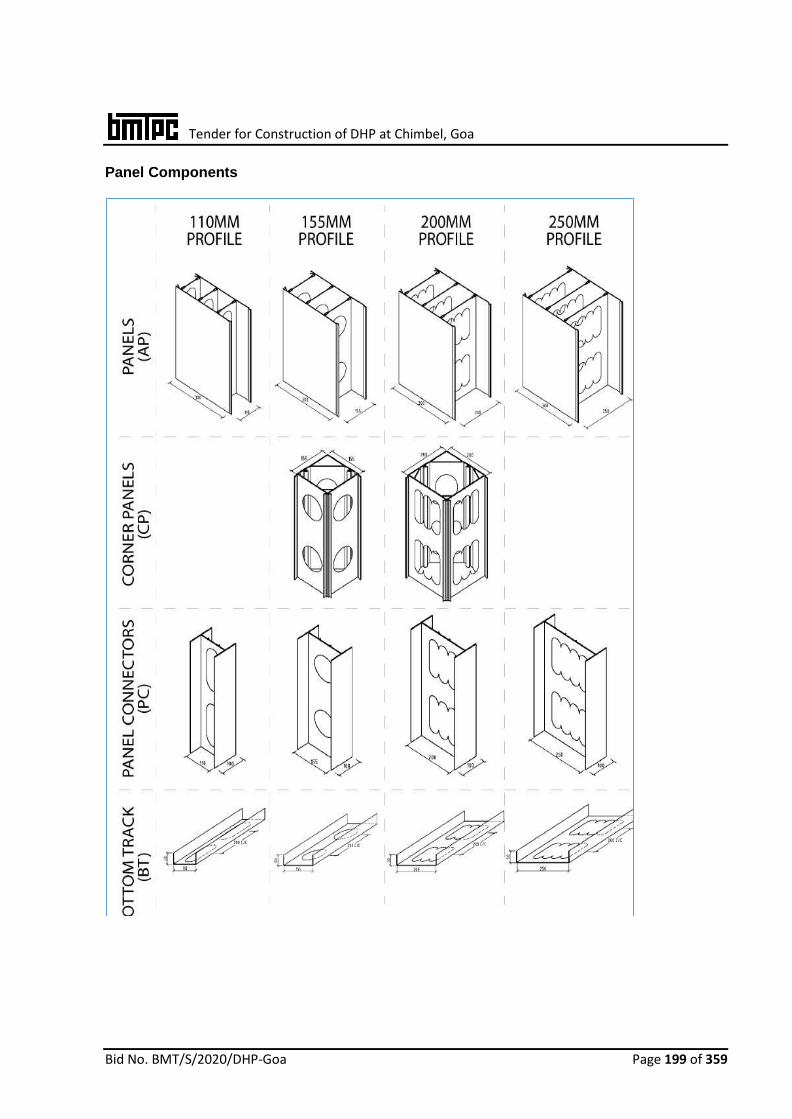
Tender for Construction of DHP at Chimbel, Goa
Bid No. BMT/S/2020/DHP-Goa Page 199 of 359
Panel Components

Tender for Construction of DHP at Chimbel, Goa
Bid No. BMT/S/2020/DHP-Goa Page 200 of 359

Tender for Construction of DHP at Chimbel, Goa
Bid No. BMT/S/2020/DHP-Goa Page 201 of 359
Uses and Limitations of System: Uses: As high capacity vertical and shear load bearing structural walling in multi-storey construction: the Permaform Wall shall be filled with reinforced concrete suitably designed to resist the combined effect of lateral and gravity loading. Limitations for using Permaform System on the basis of performance, safety, geo-climatic Conditions:
Tender for Construction of DHP at Chimbel, Goa
Bid No. BMT/S/2020/DHP-Goa Page 202 of 359
Permanent PVC Forms Walls shall need preplanned & installed MEP/Services for concealed network.
Door and Window position shall not be changed after pouring of concrete.
Erection of panels shall be under supervision of trained staff. Design Consideration: General The aim of structural design is to provide a structure that is durable, serviceable and has adequate strength. The standard sets out minimum requirements for the design and construction of concrete structures and members that contain reinforcing steel or tendons or both. It also sets out minimum requirements for plain concrete members. Walls shall be designed to accommodate a wide range of axial, wind and seismic load conditions, using the equations developed for conventional and slender concrete walls. However, one of the unique properties of Permaform walls is the ability of the permanent polymer formwork to provide concrete confinement and reinforce the concrete in tension. There are two main structural elements used in the wall, namely panel sections and connectors. The webs of these elements have cores which allow lateral flow of the poured concrete between the adjacent cells and provide a mechanical transfer of forces between the concrete and the polymer thus creating a composite action. Structural
1. The buildings constructed with Permaform walls shall be studied and designed as reinforced concrete structure since the parameters required for their design are the same as needed for traditional reinforced concrete.
2. The system is intended for use where Architectural drawings are available and satisfy the various requirements. The Architects and the design team of the concerned developer (client) is responsible for the drawings and overall building design to comply with the various regulatory requirements applicable to the area.
3. The architects shall liaise with the engineer of the developer and provide the necessary loading information for the design of the foundation.
4. The system shall be designed to provide the required performance against the loads to be considered in accordance with codes and the data given by manufacturer for various panels. It shall also provide the required bearing resistance for earthquake and wind forces as per codes wherever applicable.
5. Foundation shall be specifically designed in accordance with provision given in IS 1904:2005. The design concept is same as that of the conventional building design. The safe bearing capacity and soil properties (soil investigation report) shall be provided from the site after soil investigations. Foundation shall be designed based on the soil investigation report. Panels should have starter bars from either foundation or ground floor slab. All foundations should be designed by experienced engineer with appropriate reference.
6. The design assumptions, detailed calculations, references to necessary and detailed design drawings shall be made available on demand, if required. The structural design calculations should clearly demonstrate structural integrity and stability including connection details. Design calculations should have proper sketches annotated in English.In addition, any other requirement regarding safety against earthquake need to be ensured by the designer as per prevailing codal requirements.

Tender for Construction of DHP at Chimbel, Goa
Bid No. BMT/S/2020/DHP-Goa Page 203 of 359
Structural applications:
Raw Materials
Sr. No. Major Raw materials/ components 1 PVC-Resin 2. Calcium carbonate (CaCO3) 3. Titanium dioxide (TiO2) 4. Polyethylene Wax
Construction and Workmanship Erection of panels
1. As per the building plan and design, each wall component shall be cut using an automated cutting saw with a fine-tooth blade or grinder fitted with a cutting blade.
2. The Surveyor shall ensure that the walls are clearly and accurately set out. Alignment of bottom track shall be marked and fixed with enough fixtures to ensure the bottom track is securely fastened to the concrete footing or slab.
3. The first course shall begin with a corner piece and the two adjacent panels. The corner piece and adjacent panels needs to be plumbed from adjacent faces.

Tender for Construction of DHP at Chimbel, Goa
Bid No. BMT/S/2020/DHP-Goa Page 204 of 359
4. If a panel needs to be cut down to fit within the required dimension (therefore removing a panel anchor), a panel connector shall slide down between the two panels and be secured by screws. It shall be ensured that all the internal rib holes align with each other for the free circulation of concrete through the panels.
5. The pieces shall be checked to ensure that the correct components are installed and properly oriented and that the coring is aligned.
6. Bracing shall be provided at the top and bottom of the corner assembly and the components are screwed together at the top after the assembly is accurately plumbed. Bracing shall be screwed to the panels using one screw per brace ensuring that the screws engaged with the panel face.
7. The erection of Permaform components shall continue sequentially, in accordance with the layout drawings, including the components for doors, windows and openings.
8. Temporary bracing and steel reinforcing bars shall be installed as the wall erection proceeds.
9. A brief checklist of points before pouring of concrete:
Metal strip on external wall corners secured by screws to the adjacent panels
Aluminum angles on top third of walls
Screws on window panels and bottom connectors
Sealant on all gaps Bracing for walls at regular intervals
Frames for doors and windows
10mm holes on window sill to ensure adequate concrete circulation eliminating voids in the panels
Placing of Reinforcement
1. Reinforcing steel bars are to be provided as specified in the structural drawings for
the project. 2. Horizontal bars shall be placed through the coring in the components. The horizontal
bars shall be spliced to wall at a maximum of 6m length. Once the next stages of panels are installed, it shall be ensured that the concurrent horizontal bar splices over the first bar as per detailed in drawings. The horizontal bars shall be lapped with the previous bars, as specified in structural drawings.
3. Vertical steel reinforcement (re-bar) required as per design shall be placed within the panel cells created by the diaphragms of the panels at regular intervals to correspond with the design of reinforcement required in the wall. The vertical bars shall be tied to the foundation dowels by lifting the connectors approximately 12" (300 mm). This must be done prior to placing the horizontal bars except corners. This will provide solid attachment to footings. The vertical re-bar is most easily put in place full length after the wall assembly is erected and prior to concrete placement. The top of the vertical bar must be tied to the top horizontal bar securing its location.

Tender for Construction of DHP at Chimbel, Goa
Bid No. BMT/S/2020/DHP-Goa Page 205 of 359
4 At the first corner, the hooked horizontal bars are installed from both directions. Horizontal hooked bars are installed at the ends of straight walls prior to installing the next corner and are installed at intersections after erecting a sufficient length of wall.
Concrete Pour 1. Prior to starting concrete pour, the bracing must be re-checked to ensure that all members
are properly installed and that the Permaform walling System components are located, aligned and firm.
2. Concrete shall be poured by boom pump with a 50mm dia. end hose. The concrete specified shall be self-compacting, highly workable, free flowing mix poured from the top into the cavities or as detailed. For small building construction, concrete can be poured manually using a funnel.
3. Filling the panels with concrete shall be done as per pour sequence table shown below. The panels will withstand the dynamic bursting pressure of fresh concrete. Extra midway horizontal bracing is required for panels more than 4m in height. 4. When normal concrete is used, then the use of 25mm concrete vibrator may be recommended to achieve full circulation of concrete around congested areas of reinforcement. Gravitational pressure acts to self-compact the concrete inside the water tight cavities when self-compacting concrete is used.
4. It is preferable and recommended to use SCC (Self compacted concrete) at 150mm slump, such that, it flows freely to all the corners. Gravitational pressure acts to self-compact the concrete inside the water tight cavities when self-compacting concrete is used.
Electric and Plumbing Ducts The electric and plumbing ducts etc. shall be placed inside the ducts prior to the concrete pour.

Tender for Construction of DHP at Chimbel, Goa
Bid No. BMT/S/2020/DHP-Goa Page 206 of 359
(i) Inspections & Testing Inspections & testing shall be done at appropriate stages of manufacturing process of all the elements. The inspected panels shall be stored & packed to ensure that no damage occurs during transportation.

Tender for Construction of DHP at Chimbel, Goa
Bid No. BMT/S/2020/DHP-Goa Page 207 of 359
12. ADVANCED BUILDING SYSTEM – EMMEDUE
ABOUT THE TECHNOLOGY Expanded Polystyrene (EPS) Core Panel System is based on factory made panels, consisting of self extinguishing expanded polystyrene sheet (generally corrugated) with minimum density of
15 Kg/m3, thickness not less than 60 mm, sandwiched between two engineered sheet of welded wire fabric mesh, made of high strength galvanized wire of 2.5 mm to 3 mm dia. A 3 mm to 4 mm dia galvanized steel truss wire is pierced completely through the polystyrene core at the offset angle for superior strength and welded to each of the outer layer sheet of steel welded wire fabric mesh. The panels are finished at the site using minimum 30 mm thick shotcrete of cement & coarse sand in the ratio of 1:4 applied under pressure. (Refer sectional details as shown). The shotcrete coat encases the EPS Core with centrally placed steel welded wire fabric mesh.
The technology (developed about 30 years back) has been successfully used in many countries like Morocco, Algeria, South Africa, Kenya, Austria, Malasiya, Ireland, Romania & Australia with involvement of different agencies and brand names.
PANEL TYPES
The Panels being manufactured are of different types depending upon the application. The details of different types of typical panels are given below:
Single Panel for structural uses
Longitudinal wire 2.5 mm / 3.5 mm ø spaced @ 65
mm
Transverse Wire 2.5 mm ø spaced @ 65 mm
Cross Steel Wire 3.0 mm ø approx 68 nos. / m2
Polystyrene Core Density ≥15 Kg/m3,
Thickness not less than 60 mm
Finished Masonry Not less than 130 mm thick
Single Panel for Internal partition, external walls and insulation
Longitudinal wire 2.5 mm ø spaced @ 70 mm
Transverse Wire 2.5 mm ø spaced @ 70 mm
Cross Steel Wire 3.0 mm ø approx 68 nos. / m2
Polystyrene Core Density ≥ 15 Kg/m3,
Thickness 40 mm to 320
mm Finished Masonry 90 mm to 370 mm thick
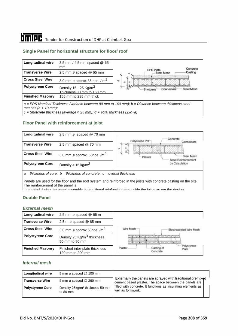
Tender for Construction of DHP at Chimbel, Goa
Bid No. BMT/S/2020/DHP-Goa Page 208 of 359
Longitudinal wire 5 mm ø spaced @ 100 mm
Transverse Wire 5 mm ø spaced @ 260 mm
cement based plaster. The space between the panels are
Polystyrene Core Density 25kg/m3 thickness 50 mm
to 80 mm filled with concrete. It functions as insulating elements as well as formwork.
Single Panel for horizontal structure for floor/ roof
Longitudinal wire 3.5 mm / 4.5 mm spaced @ 65
mm
Transverse Wire 2.5 mm ø spaced @ 65 mm
Cross Steel Wire 3.0 mm ø approx 68 nos. / m2
Polystyrene Core Density 15 - 25 Kg/m3
Thickness 80 mm to 160 mm
Finished Masonry 155 mm to 235 mm thick
a = EPS Nominal Thickness (variable between 80 mm to 160 mm); b = Distance between thickness steel meshes (a + 10 mm);
c = Shotcrete thickness (average ≥ 25 mm); d = Total thickness (2xc+a) Generally used for buildings of not more than 4 storeys for floor and covering slabs with maximum span of 4 m.
Floor Panel with reinforcement at joist
Longitudinal wire 2.5 mm ø spaced @ 70 mm
Transverse Wire 2.5 mm spaced @ 70 mm
Cross Steel Wire 3.0 mm ø approx. 68nos. /m2
Polystyrene Core Density ≥ 15 kg/m3
a = thickness of core; b = thickness of concrete; c = overall thickness Panels are used for the floor and the roof system and reinforced in the joists with concrete casting on the site. The reinforcement of the panel is
integrated during the panel assembly by additional reinforcing bars inside the joists as per the design.
Suitable upto 8m span with the live load of up to 4 kN/m2.
Double Panel
External mesh Longitudinal wire 2.5 mm ø spaced @ 65 m
Transverse Wire 2.5 m ø spaced @ 65 mm
Cross Steel Wire 3.0 mm ø approx 68nos. /m2
Polystyrene Core Density 25 Kg/m3 thickness
50 mm to 80 mm
Finished Masonry Finished inter-plate thickness
120 mm to 200 mm
Internal mesh
Externally the panels are sprayed with traditional premixed
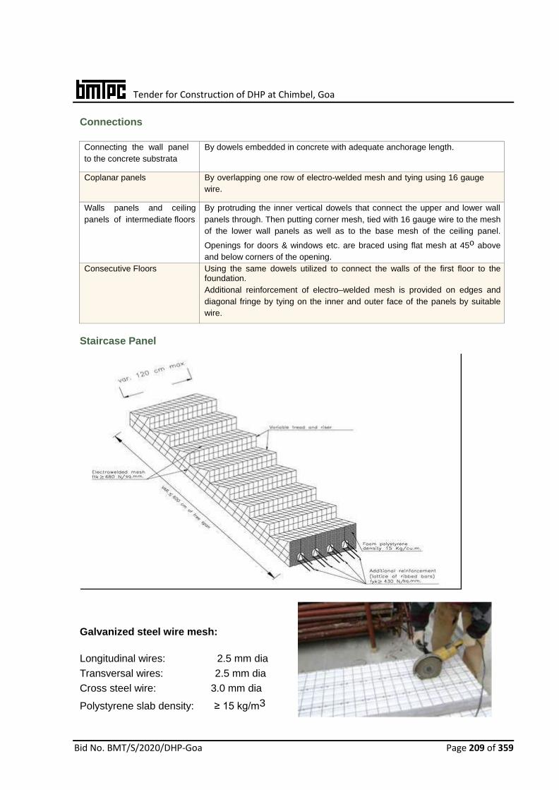
Tender for Construction of DHP at Chimbel, Goa
Bid No. BMT/S/2020/DHP-Goa Page 209 of 359
Connections
Connecting the wall panel
to the concrete substrata
By dowels embedded in concrete with adequate anchorage length.
Coplanar panels By overlapping one row of electro-welded mesh and tying using 16 gauge
wire.
Walls panels and ceiling
panels of intermediate floors
By protruding the inner vertical dowels that connect the upper and lower wall
panels through. Then putting corner mesh, tied with 16 gauge wire to the mesh
of the lower wall panels as well as to the base mesh of the ceiling panel.
Openings for doors & windows etc. are braced using flat mesh at 45o above
and below corners of the opening.
Consecutive Floors Using the same dowels utilized to connect the walls of the first floor to the foundation.
Additional reinforcement of electro–welded mesh is provided on edges and
diagonal fringe by tying on the inner and outer face of the panels by suitable
wire.
Staircase Panel
Galvanized steel wire mesh: Longitudinal wires: 2.5 mm dia
Transversal wires: 2.5 mm dia
Cross steel wire: 3.0 mm dia
Polystyrene slab density: ≥ 15 kg/m3
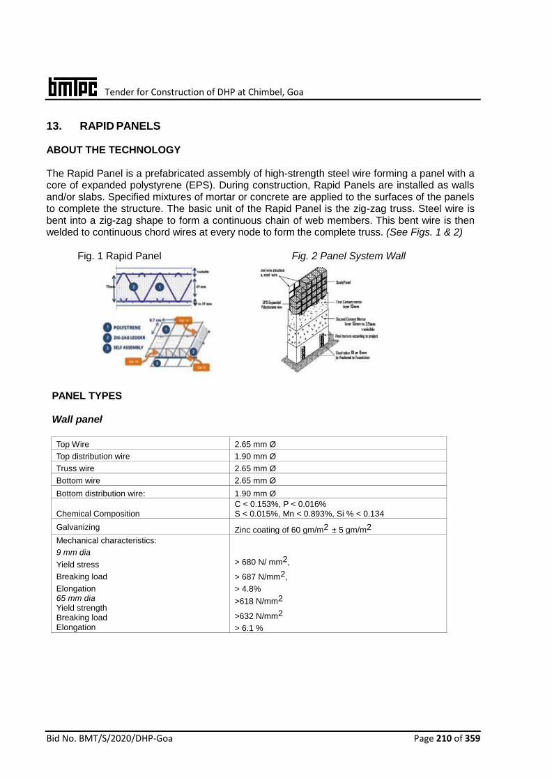
Tender for Construction of DHP at Chimbel, Goa
Bid No. BMT/S/2020/DHP-Goa Page 210 of 359
13. RAPID PANELS ABOUT THE TECHNOLOGY The Rapid Panel is a prefabricated assembly of high-strength steel wire forming a panel with a core of expanded polystyrene (EPS). During construction, Rapid Panels are installed as walls and/or slabs. Specified mixtures of mortar or concrete are applied to the surfaces of the panels to complete the structure. The basic unit of the Rapid Panel is the zig-zag truss. Steel wire is bent into a zig-zag shape to form a continuous chain of web members. This bent wire is then welded to continuous chord wires at every node to form the complete truss. (See Figs. 1 & 2)
Fig. 1 Rapid Panel Fig. 2 Panel System Wall
PANEL TYPES
Wall panel
Top Wire 2.65 mm Ø
Top distribution wire 1.90 mm Ø
Truss wire 2.65 mm Ø
Bottom wire 2.65 mm Ø
Bottom distribution wire: 1.90 mm Ø
Chemical Composition
C < 0.153%, P < 0.016% S < 0.015%, Mn < 0.893%, Si % < 0.134
Galvanizing Zinc coating of 60 gm/m2 ± 5 gm/m2
Mechanical characteristics:
9 mm dia
Yield stress
Breaking load
Elongation 65 mm dia Yield strength Breaking load Elongation
> 680 N/ mm2,
> 687 N/mm2,
> 4.8%
>618 N/mm2
>632 N/mm2
> 6.1 %
Tender for Construction of DHP at Chimbel, Goa
Bid No. BMT/S/2020/DHP-Goa Page 211 of 359
Polystyrene Core
Density > 15 kg/m3, Flammability: Non Flammable,
Moisture Continent at 50ºC: <1.1%
Thickness: not < 50 mm
Bead size: shall be > 95% between
0.5 – 1.12 mm as per ASTM C 578
Cast-in-place concrete
The min. grade of concrete is M20
and slump for walls, floors and roofs
shall be as per IS 456:2000
Cement Plaster Shall have a minimum 28-day compressive strength
Roof Panel Top Wire 2.65 mm Ø
Top distribution wire 1.90 mm Ø
Truss wire 2.65 mm Ø
Bottom wire 5.00 mm Ø
Bottom distribution wire: 1.90 mm Ø
Chemical Composition
C < 24%, P < 0.055%
S < 0.055%, Ceq< 0.52%
Galvanizing Zinc coating of 60 gm/ m2 ± 5 gm/m2
Mechanical characteristics:
9 mm dia
Yield stress
Breaking load
Elongation
65 mm dia
Yield strength
Breaking load
Elongation
5.00 mm dia
> 680 N/ mm2,
> 687 N/mm2,
> 4.8%
>618 N/mm2
>632 N/mm2
> 6.1 %
Yield strength
Breaking load
Elongation
670 N/ mm2,
816 N/mm2,
> 14%
Polystyrene Core
Density > 15 kg/m3, Flammability: Non Flammable,
Moisture Conti- nent at 50ºC: <1.1%
Thickness: not < 50 mm
MATERIAL REQUIREMENTS Galvanised high strength steel wire: Fe 500 & Fe 550 as per IS 1786: 2008 Ordinary Portland Cement: 43 grade as per IS 269:2015. Fine aggregate: 4.7 mm size for concrete as per IS 383:2016 and plaster of sand 150 micron – 2.36 mm as per IS 1542:1992 Coarse Aggregate: of 20 mm & 40 mm size as per IS 383:2016. Steel reinforcement: as per IS 1786:2008. Gypsum Plaster board: as per IS 2095 (Part 1):2011.

Tender for Construction of DHP at Chimbel, Goa
Bid No. BMT/S/2020/DHP-Goa Page 212 of 359
Adhesive: as per ASTM 881 Plasticizers: as per IS 9103:1999 Waterproofing compound: as per IS 2645:2003 Fibers: Polypropylene fiber mesh as per EN 14889-2:2006 Ledger Bolt: Consists of 12.7 mm diameter L-shaped bolt with washers and nuts as per
ASTM A 307. It shall be fastened to the panel wire sand plastered.
Hartco clips: Formed from 11.11mm-wide, No. 20 gauge cold-rolled steel and manufactured by Stanley Hartco or
Spenax Flex-C-Rings, No. 516 G100. CONSTRUCTION PROCESS
The construction process of the panels is as follows:
The shop-fabricated panels consist of welded wire zig-zag trusses and a foam plastic core to which structure plaster shall be applied on each side. The panels have vertical 75 mm deep 14 gauge (1.63 mm) wire trusses spaced at 50 mm centers with preformed 57 mm thick expanded polystyrene (EPS) foam strips between. The assembly is held together with 14 gauge horizontal wires on each face at 50 mm centers electro welded to the truss chords. The horizontal wires and vertical truss chords shall project 10 mm approx. beyond each foam plastic face to permit wire embedment within cement and gypsum plaster finish applied to each face after erection on the site.
The panels are manufactured in 1.22 m widths and varying heights from 1.52 m to 3.55 m in increments of 100 mm. The nominal thickness of the panel is 75 mm resulting in a finished wall thickness, after plastering, of 100 mm or more.
IMPLEMENTATION
Panel System
Raft foundation
For only ground floor and G+1 unit constructions. When the soil is
strong or when the soil is improved, this is done by using a slab/raft
foundation.
Strip foundation
For only ground floor and G+1 unit constructions. When the surface
soil is in a terrain with vegetation or lime, and it is required to locate
the foundation in a stronger and deeper layer, this is done by using a
strip footing.
Existing foundation
When a foundation already exists or when something is being
constructed over existing construction, steps given below shall be
followed:
(i) Holes of 8 or 10 mm dia. of 100 mm depth every 400 mm shall be drilled and lined up with

Tender for Construction of DHP at Chimbel, Goa
Bid No. BMT/S/2020/DHP-Goa Page 213 of 359
inside of the wall.
(ii) High strength steel bars of 8 or 10 mm dia. shall be placed in every hole leaving 400 mm of
height above the foundation.
(iii) The wall panel shall be tied with bars of 8 or 10 mm dia. on the outside of the mesh with
steel wire, with a minimum of 3 ties per bar.
Boundary Wall
Following procedure shall be followed for construction of boundary walls:
i) Bars of 8 or 10 mm dia shall be placed on top of the foundation, alternating one on the
outside of the founda- tion and the other on the inside every 400 mm. ii) The bars that are placed on the inside shall be bent in such a way that they are rooted in
the foundation. iii) The wall panel shall be located on the soil and plastered on the bordering side. They
shall be placed in groups of two or three. iv) The mortar layer shall be dried, and the wall panel erected while straightening he interior
bars. v) Finally, the wall panels shall be tied to the bars on both sides perfectly and plastered on
the interior.
Wall Panels
Exterior wall panels shall be set with a minimum 6 mm clearance between the concrete slab edge and the panel reinforcement. The slab shall be attached with perimeter 63 mm-long by 3 mm thick steel hold-down connector channels and 13 mm diameter foundation bolts placed at a distance of 1.22 m max. centers along width and at each panel end. Panel reinforcement and connector channels shall be attached with 305 mm long, 12 gauge (2.06 mm) wires extending approximately 45 degrees upward along each panel face from each channel end. The upper end of the diagonal wires shall be attached to the panel reinforcement. Panels shall be joined along vertical edges with 203 mm wide strips of 14 gauge 51 square mm welded wire mesh on each face centered on the panel joint. The mesh shall be attached to the vertical panel wire reinforcement with Hartco clips spaced 305 mm on center at the edge wires and 610 mm on center at interior wire Panels shall also be joined on both sides with 14 gauge wire trusses).
Interior wall panels shall be set and attached to hold-down
connector channels with 12 gauge wires in the same
manner as exterior panels. Approved powder-actuated
anchors shall be used, provided they are adequate for
applicable uplift loads. A nonstructural plaster ground shall
be attached at the base of the interior panels if desired.
Roof and Floor Panels
The panels shall not be permitted to bear on wood-frame
walls. Horizontal diaphragms shall be permitted the same
shear values as vertical racking shear, provided the panels
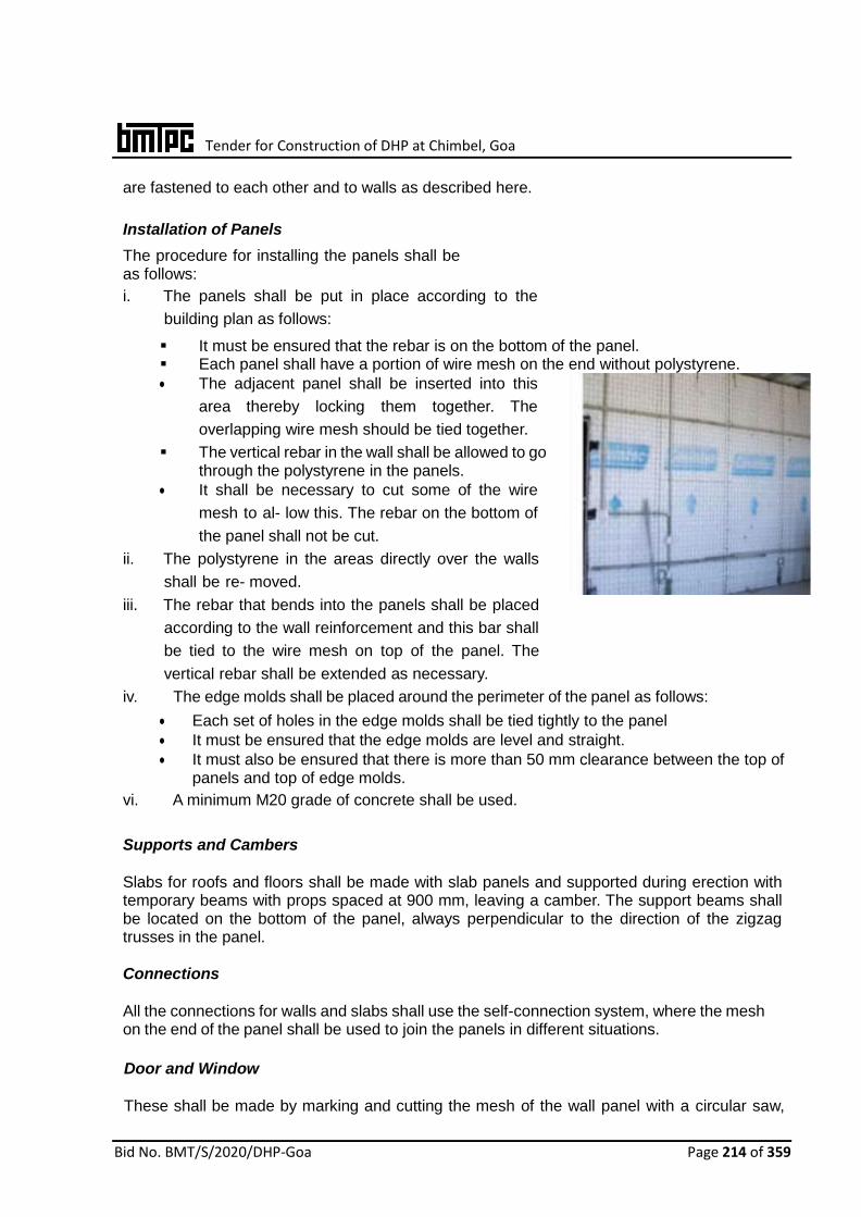
Tender for Construction of DHP at Chimbel, Goa
Bid No. BMT/S/2020/DHP-Goa Page 214 of 359
are fastened to each other and to walls as described here.
Installation of Panels
The procedure for installing the panels shall be as follows:
i. The panels shall be put in place according to the
building plan as follows:
It must be ensured that the rebar is on the bottom of the panel. Each panel shall have a portion of wire mesh on the end without polystyrene.
The adjacent panel shall be inserted into this
area thereby locking them together. The
overlapping wire mesh should be tied together.
The vertical rebar in the wall shall be allowed to go through the polystyrene in the panels.
It shall be necessary to cut some of the wire
mesh to al- low this. The rebar on the bottom of
the panel shall not be cut.
ii. The polystyrene in the areas directly over the walls
shall be re- moved.
iii. The rebar that bends into the panels shall be placed
according to the wall reinforcement and this bar shall
be tied to the wire mesh on top of the panel. The
vertical rebar shall be extended as necessary.
iv. The edge molds shall be placed around the perimeter of the panel as follows:
Each set of holes in the edge molds shall be tied tightly to the panel
It must be ensured that the edge molds are level and straight.
It must also be ensured that there is more than 50 mm clearance between the top of panels and top of edge molds.
vi. A minimum M20 grade of concrete shall be used. Supports and Cambers
Slabs for roofs and floors shall be made with slab panels and supported during erection with temporary beams with props spaced at 900 mm, leaving a camber. The support beams shall be located on the bottom of the panel, always perpendicular to the direction of the zigzag trusses in the panel.
Connections
All the connections for walls and slabs shall use the self-connection system, where the mesh on the end of the panel shall be used to join the panels in different situations.
Door and Window
These shall be made by marking and cutting the mesh of the wall panel with a circular saw,
Tender for Construction of DHP at Chimbel, Goa
Bid No. BMT/S/2020/DHP-Goa Page 215 of 359
reciprocating saw, or with wire cutters, and reinforcing the edges on both sides with zigzag mesh. The zigzag mesh should extend 300 mm from the edges of the doors and windows. Afterwards, diagonal zigzag mesh shall be installed on every corner of 400 mm.
Where edges and corners are reinforced, the poly- styrene along the perimeter of the opening shall be removed and the space is filled with mortar or con- crete to form a rigid boundary. In the area on top of the opening, the polystyrene shall be removed and reinforcing steel placed to form a lintel beam.
Plumbing and Electrical Fixtures
Water pipes and electrical conduits shall be placed within the panels as shown in the building plans by re- moving polystyrene from the portion. For layers pipes wire mesh shall be cut. Good practices of electrical and plumbing services shall be adopted.
Plumb and Alignment
It shall be assured that the wall panel is plumb and in line, and to maintain right angles between them, tension wire and metal rulers shall be used. The poly- styrene in the center of the panel shall be toothed on the surface to ensure better mortar connection and less wastage.
Finishing
i. Floor finishing
• It must be ensured that the floor area is completely clear of any debris, dust and soil etc. • It must be ensured that the floor surface is
damp prior to finishing and it should be fully moist without any water stagnating on it.
• Cement mortar of mix 1 cement: 3 sand shall be prepared and required quantity of mortar shall be applied to the floor to provide a smooth finish.
ii. Ceiling finishing
A stiff mix of 1 cement: 3 sand mortar shall be prepared and applied to the ceiling, providing a level but rough surface.
It must be ensured that the first layer of plaster is damp prior to applying the finish layer.
Cement mortar of mix 1 cement: 4 sand shall be prepared and required quantity of mortar shall be applied to the ceiling to provide a smooth finish.
The total thickness of the ceiling finish should not exceed 19 mm below the panel wire mesh.
iii. Wall finishing
• Cement mortar of mix 1 cement: 4 sand shall be prepared and 25 mm plaster shall be applied to the pre- damp wall to give a finish surface.
• Wall plaster should be allowed to be cured for at least 7 days after placement.
Tender for Construction of DHP at Chimbel, Goa
Bid No. BMT/S/2020/DHP-Goa Page 216 of 359
14. REINFORCED EPS CORE PANEL SYSTEM Reinforced Expanded Polystyrene Core (EPC) Panel System is a factory produced panel system for the construction of low rise buildings upto G+3 and as filler walls in high rise RCC and steel frame buildings. In this technique, a core of undulated polystyrene is covered with interconnected zinc coated welded wire mesh on both sided reinforcement and shortcrete concrete. The panels are finished on site by pouring concrete (double panel, floors and stairs) and spraying concrete to realise the following different elements of the system: • Vertical Structural Walls • Horizontal Structural elements • Cladding elements PANEL TYPES The panels are of three types depending upon the application as shown below: Single load bearing Panel
Longitudinal wires 2.5 /3.0 mm Ø @80 mm c/c
Transverse wires 2.5 /3.0 mm Ø @80 mm c/c
Connectors & cross wires 3.0 mm Ø @ 150 mm c/c
Polystyrene core conforming to IS 4671
Density : ≥ 15 kg/m3 Thickness: 50 mm to 160 mm Wave Depth: 15 mm
Finished Masonry Not less than 130mm thick
Single Non Load Bearing Panel
Longitudinal wires 2.5 /3.0 mm Ø @80 mm c/c
Transverse wires 2.5 /3.0 mm Ø @80 mm c/c
Connectors & cross wires 3.0 mm Ø @ 150 mm c/c
Polystyrene core
Density : ≥ 15 kg/m3 Thickness: 40 mm to 280 mm Wave Depth: 5 mm
Finished Masonry 90 to 370mm thick
Single Floor Panel Used as floors or roofs span upto 5 m x 5m and supported by the walls in all the sides. The panels are finished on site by 50 mm of casted concrete in upper side and 30 mm of projected plaster in the lower side.

Tender for Construction of DHP at Chimbel, Goa
Bid No. BMT/S/2020/DHP-Goa Page 217 of 359
Longitudinal wires 2.5 /3.0 mm Ø @80 mm c/c
Transverse wires 2.5 /3.0 mm Ø @75 mm c/c
Connectors & cross wires 3.0 mm Ø @ 150 mm c/c
Polystyrene core
Density : ≥ 15 kg/m3 Thickness: 80 mm to 160 mm Wave Depth: 5 mm
Finished Masonry Not less than 80mm thick
Two Pot Floor Panel With span up to 9 m, these panels are characterized by the presence of joist. The joists are reinforced on site by the steel bars according to the structural verification and are finished by 40 mm of casted concrete (M25) on the upper side and 25 mm of projected plaster (M15) in the lower side.
Longitudinal wires 2.5 /3.0 mm Ø @80 mm c/c
Transverse wires
2.5 /3.0 mm Ø @75/150 mm c/c
Connectors & cross wires 3.0 mm Ø @ 150 mm c/c
Polystyrene core
Density : ≥ 15 kg/m3 Thickness: 40 mm to 280 mm Wave Depth: 5 mm
Finished Masonry Not less than 65mm thick
Material Requirements Steel for both wire mesh and connectors. Zinc Coating – The zinc covering is variable with the diameter of the wire mesh. Standard wire
mesh shall be 3.0 mm dia and minimum zinc coating galvanizing shall be of 60 gm/m2. Mechanical characteristics
Tensile strength (2.5 mm Ø) : ≮ 750 N/mm2
Tensile strength (3.0 mm Ø) : ≮ 700 N/mm2
Yield strength (2.5 mm Ø) : ≮ 680 N/mm2
Yield strength (3.0 mm Ø) : ≮ 600 N/mm2
Elongation : > 8% Chemical characteristics % C : < 0.24 %P : < 0.055 %S : Max 0.045 %Ceq : <0.52 %Si : 0.300 – 0.600
Tender for Construction of DHP at Chimbel, Goa
Bid No. BMT/S/2020/DHP-Goa Page 218 of 359
The panels are used as: i) Load bearing walling in buildings ii) non- load bearing wall panels iii) partition infill wall in multi storey framed buildings iv) floor / roof slabs
Installation Procedure Foundations Foundations for the EPS Core Panel system whether strip or raft are conventional. If strip foundations are used, they should be levelled and stepped as this makes panel positioning easier. For EPS Core panels, parallel sided timber or metal template of the width of panel shall be required to mark the position of the wall panels on the foundation and the spacing of the starter bar holes. Wall start-up • Line wall positions shall be marked and profiled. • A timber or metal template of the exact width of panel (from wire to wire) shall be used to
mark the position of the panels with chalk or pencil lines. • On the panel, lines positions shall be marked to drill the starter bar holes. These should
be in a zig zag pattern at 600 mm centres on each side of the panels. Starter bars should be at all panel joints and on the opposite side in mid panel plus at all wall corners and joints.
• Starter bars should be either 6 mm or 8 mm dia. 500 mm long with 100 mm drilled into the foundations and 400 mm above.
• Drill bits shall be used to give a tight fit with the starter bars. • Once starter bars are in position, EPS Core panels shall be placed between the starter
bars, starting from a corner. Starter bars shall be wire-tied to the panel mesh and the panels to each other on the overlapping mesh.
Wall construction • All corners and wall joints shall be reinforced with right angled wire mesh to the full height
of the walls. • To cut panels to fit for door & window openings, wire should be cut with a wire cutter or
angle grinder. Mea- sure and mark the cut lines before starting to cut. • After the wire mesh has been cut, EPS shall be cut with a hacksaw blade or stiff blade
hand saw. • Added steel mesh reinforcement shall be required around door and window openings to
ensure that no plaster cracks form in these areas. Mesh reinforcement strips shall be tied diagonally with wire around openings before plastering.
• Once wall panels are in place and tied together, bracing shall be required to hold them vertical before plastering. This shall be done only on one side of the panels.
• Once the panels are plastered on one side, the wall bracing shall be removed after 24 h. Plastering on other side can be done without bracing.
Door and Window fittings • Fix a metal angle iron or hollow tube sub frame into the openings before plastering. Fix and
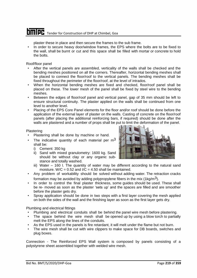
Tender for Construction of DHP at Chimbel, Goa
Bid No. BMT/S/2020/DHP-Goa Page 219 of 359
plaster these in place and then secure the frames to the sub frame. • In order to secure heavy door/window frames, the EPS where the bolts are to be fixed to
the wall, shall be burnt or cut and this space shall be filled with mortar or concrete to hold the bolts.
Roof/floor panel • After the vertical panels are assembled, verticality of the walls shall be checked and the
bending meshes positioned on all the corners. Thereafter, horizontal bending meshes shall be placed to connect the floor/roof to the vertical panels. The bending meshes shall be fixed throughout the perimeter of the floor/roof, at the level of intrados.
• When the horizontal bending meshes are fixed and checked, floor/roof panel shall be placed on these. The lower mesh of the panel shall be fixed by steel wire to the bending meshes.
• Between the edges of floor/roof panel and vertical panel, gap of 35 mm should be left to ensure structural continuity. The plaster applied on the walls shall be continued from one level to another level.
• Placing of the EPS Core Panel elements for the floor and/or roof should be done before the application of the external layer of plaster on the walls. Casting of concrete on the floor/roof panels (after placing the additional reinforcing bars, if required) should be done after the walls are plastered and a number of props shall be put to limit the deformation of the panel.
Plastering • Plastering shall be done by machine or hand.
• The indicative quantity of each material per m3
shall be: i) Cement: 350 kg ii) Sand with mixed granulometry: 1600 kg. Sand
should be without clay or any organic sub- stance and totally washed.
iii) Water – 160 l. The quantity of water may be different according to the natural sand moisture. W/C = 0.52 and I/C = 4.50 shall be maintained.
• Any problem of workability should be solved without adding water. The retraction cracks
formation may be avoided by adding polypropylene fibers in the mix (1kg/m3). • In order to control the final plaster thickness, some guides should be used. These shall
be re- moved as soon as the plaster ‘sets up’ and the spaces are filled and are smoother before the plaster gets dry.
• Spray application should be done in two steps with a first layer covering the mesh applied on both the sides of the wall and the finishing layer as soon as the first layer gets dry.
Plumbing and electrical fittings • Plumbing and electrical conduits shall be behind the panel wire mesh before plastering. • The space behind the wire mesh shall be opened up by using a blow torch to partially
melt the EPS along the lines of the conduits. • As the EPS used in the panels is fire retardant, it will melt under the flame but not burn. • The wire mesh shall be cut with wire clippers to make space for DB boards, switches and
plug boxes. Connection - The Reinforced EPS Wall system is composed by panels consisting of a polystyrene sheet assembled together with welded wire mesh.

Tender for Construction of DHP at Chimbel, Goa
Bid No. BMT/S/2020/DHP-Goa Page 220 of 359
15. QUICKBUILD 3D PANELS In quick build 3 D Panel system, the panels consist of fire resistant grade insulated polystyrene core, two engineered layers of Galvanized Steel Mesh and galvanized steel trusses. The steel trusses are pierced through the polystyrene core and welded to the outer layer sheets of Galvanized steel mesh.
The wall panel is placed in position and a wythe of structural plaster is applied to both sides. The wall panel receives its strength and rigidity from the diagonal cross wires welded to the welded-wire fabric on each side. This combination produces a truss behavior, which provides rigidity and shear terms for a full composite behavior.
The shell of the structure is built by manually erecting the panels directly onto the slab with reinforcement rods. Desired utilities like doors, windows and ventilators may be pre-built while plumbing, electrical conduits may be added onsite.
These panels are used in the construction of exterior and interior load-bearing and
non-load bearing walls and floors of buildings of all types of construction. The details of these panels are shown in figures given at the right.
PANEL TYPES
The panels being manufactured are of three types depending upon the application. The
details of different types of typical panels are given below:
Wall Panel Longitudinal wire 2.5 mm Ø @ 50 mm
Transverse 2.5 mm Ø @ 50 mm
Steel truss wire 3.0 mm Ø pierced through the core at
offset angle @ 100 mm spacing Chemical Composition C < 0.24%, P < 0.055%
S < 0.055%, Ceq< 0.52% Galvanizing Zinc coating of 60 gm/
m2 ± 5 gm/m2 Mechanical characteristics: Yield stress Breaking load Elongation
> 600 N/ mm2,
> 680 N/mm2,
> 8%
Polystyrene Core Density > 15 kg/m3
thickness 50/80/100 mm Self-load 120 kg/m2 Load bearing 350 kN/m
Plaster ratio: In two coats
1st coat of 20 mm of 1:2:3 (1 cement: 2 sand: 3 chips) 2nd coat of 10 mm of 1:5 (1 cement: 5 sand)
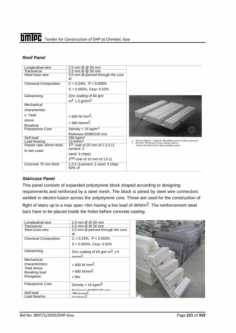
Tender for Construction of DHP at Chimbel, Goa
Bid No. BMT/S/2020/DHP-Goa Page 221 of 359
Roof Panel
Longitudinal wire 2.5 mm Ø @ 50 mm Transverse 2.5 mm Ø @ 50 mm Steel truss wire 3.0 mm Ø pierced through the core
at
offset angle @ 100 mm spacing Chemical Composition C < 0.24%, P < 0.055%
S < 0.055%, Ceq< 0.52%
Galvanizing Zinc coating of 60 gm/
m2 ± 5 gm/m2 Mechanical
characteristic
s: Yield
stress
Breaking
load
Elongation
> 600 N/ mm2,
> 680 N/mm2,
> 8% Polystyrene Core Density > 15 kg/m3
thickness 50/80/100 mm Self-load 280 kg/m2 Load bearing 10 kN/m2 Plaster ratio 30mm thick:
In two coats
1st coat of 20 mm of 1:2:3 (1 cement: 2
sand: 3 chips)
2nd coat of 10 mm of 1:5 (1
cement: 5 sand) Concrete 75 mm thick: 1:2:4 (1cement: 2 sand: 4 chips 50% of
size < 18mm + 50% of size < 10mm)
Staircase Panel
This panel consists of expanded polystyrene block shaped according to designing
requirements and reinforced by a steel mesh. The block is joined by steel wire connectors
welded in electro-fusion across the polystyrene core. These are used for the construction of
flight of stairs up to a max span <6m having a live load of 4kN/m2. The reinforcement steel
bars have to be placed inside the holes before concrete casting.
Longitudinal wire 2.5 mm Ø @ 50 mm
Transverse 2.5 mm Ø @ 50 mm Steel truss wire 3.0 mm Ø pierced through the core
at
offset angle @ 100 mm spacing Chemical Composition C < 0.24%, P < 0.055%
S < 0.055%, Ceq< 0.52%
Galvanizing Zinc coating of 60 gm/ m2 ± 5
gm/m2 Mechanical
characteristics: Yield stress Breaking load Elongation
> 600 N/ mm2,
> 680 N/mm2,
> 8%
Polystyrene Core Density > 15 kg/m3
thickness 50/80/100 mm Self-load 280 kg/m2 Load bearing 10 kN/m2

Tender for Construction of DHP at Chimbel, Goa
Bid No. BMT/S/2020/DHP-Goa Page 222 of 359
Plaster ratio 30mm thick:
In two coats
1st coat of 20 mm of 1:2:3 (1 cement: 2, sand: 3 chips)
2nd coat of 10 mm of 1:5 (1 cement: 5 sand)
Concrete 75 mm thick: 1:2:4 (1cement: 2 sand: 4 chips 50% of size < 18mm + 50% of size < 10mm)
MANUFACTURING PROCESS QuickBuild 3D panel is manufactured from welded wire space frame integrated with a
polystyrene (EPS) insulation core sandwiched between two layers of engineered galvanized
steel mesh that are held together with steel trusses. Steel trusses are pierced through the
polystyrene core and welded to the outer layer sheets of galvanized steel mesh to form a rigid
panel.
For any structure, foundation is built using conventional methods, starter bars are cast into the
slab. The panels are erected vertical in plumb and temporarily supported by way of bracing
Rebar which is set between the mesh and the polystyrene (for easy wall alignment). Splice
meshes are then fixed using fasterner tool. Door & window open- ings can be cut both before
or after panel erection. Roof panels are then erected and fastened with joining mesh.
Concealed plumbing and electrical wiring can be pre-built into the panel using hot air torch.
Subsequently, doors and windows are fixed. Structural plaster is finally applied pneumatically
on both sides and concreting of exterior side of the roof panel is done. Natural Curing is done
for concrete to gain strength.
FIXING OBJECTS TO WALLS
Light weight object: 2.5 mm screws, pins or similar
devices may be used.
Heavy object (shelves, water tanks etc.):
Plastic pins with 45 mm screws or similar
devices are rec- ommended.
Very heavy object: During erection, metal
pins may be inserted in plaster pallets.
Alternatively, threaded pins fastened with
epoxy resin may be used.
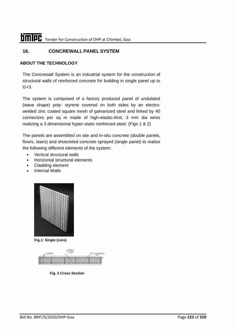
Tender for Construction of DHP at Chimbel, Goa
Bid No. BMT/S/2020/DHP-Goa Page 223 of 359
16. CONCREWALL PANEL SYSTEM
ABOUT THE TECHNOLOGY
The Concrewall System is an industrial system for the construction of
structural walls of reinforced concrete for building in single panel up to
G+3.
The system is composed of a factory produced panel of undulated
(wave shape) poly- styrene covered on both sides by an electro-
welded zinc coated square mesh of galvanized steel and linked by 40
connectors per sq m made of high-elastic-limit, 3 mm dia wires
realizing a 3 dimensional hyper-static reinforced steel. (Figs 1 & 2)
The panels are assembled on site and in-situ concrete (double panels,
floors, stairs) and shotcreted concrete sprayed (single panel) to realize
the following different elements of the system:
Vertical structural walls
Horizontal structural elements
Cladding element
Internal Walls
Fig.1: Single (core)
Fig. 2 Cross Section

Tender for Construction of DHP at Chimbel, Goa
Bid No. BMT/S/2020/DHP-Goa Page 224 of 359
PANEL TYPES
Single Bearing Panel – Used as Load Bearing Wall
Fig. 3 Single Bearing Panel Fig. 4 Single Non-load Bearing Panel
Mesh
Width : 1235 mm
Longitudinal wires : 2.5/3.0 mm ø @ 80 mm c/c (max)
Transverse wires : 2.5/3.0 mm ø @ 75 mm c/c (max)
Connectors & cross wire : 3.0 mm ø @ 150 mm c/c
EPS
Density : ≥ 15 kg/m3
Thickness : 40 mm to 240 mm
Wave Depth : 15 mm
Single Non Load Bearing Panel Mesh
Width : 1235 mm
Longitudinal wires : 2.5/3.0 mm ø @ 80 mm c/c (max)
Transverse wires : 2.5/3.0 mm ø @ 75 /150 mm c/c (max)
Connectors & cross wire : 3.0 mm ø @150 mm c/c
EPS
Density : ≥15 kg/m3
Thickness : 40 mm to 280 mm
Wave Depth : 5 /15 mm

Tender for Construction of DHP at Chimbel, Goa
Bid No. BMT/S/2020/DHP-Goa Page 225 of 359
Single Floor Panel
Used as floors or roofs span upto 5 m x 5m and supported by
the walls in all the sides. The panels are finished on site by 50
mm of casted concrete in up- per side and 30 mm of projected
plaster in the lower side.
Mesh
Width : 1235 mm
Longitudinal wires : 2.5 / 3.0 mm ø @ 80 mm c/c
Transverse wires : 2.5 / 3.0 mm ø @ 75 mm c/c
Connectors & cross wire : 3.0 mm ø @ 150 mm c/c
Fig. 5 Single Floor Panel
EPS
Width : 1200 mm
Thickness : 80 mm to 200 mm
Density : ≥15Kg/m3
Floor Panel with Joists
Galvanized steel wire mesh
Longitudinal wires : 2.5 mm ø every 70 mm
Transversal wires: : 2.5 mm ø every 70 mm
Cross steel wire: : 3.0 mm ø (approx. 68 per
m2)
Polystyrene slab density : ≥15 kg/m3
Fig. 6 Floor Panel with joists This panel is used for the floor and the roof system and it is reinforced in the joists with concrete casting on the site. The reinforcement of the panel is integrated during the panel assembly by additional reinforcing
bars inside the joists as per the design.These are suitable for slabs having spans up to 8 m and
with live loads up to 4 kN/m2.
Tender for Construction of DHP at Chimbel, Goa
Bid No. BMT/S/2020/DHP-Goa Page 226 of 359
MATERIAL REQUIREMENTS
Raw Materials
Steel for both wire mesh and connectors
Zinc Coating – The zinc covering is variable with the diameter of the wire mesh. Standard wire mesh shall be of 2.5/3.0 mm ø and zinc coating galvanizing shall be of 60/90 gm/m2 with a tolerance of ± 5 gm/m2.
Mechanical characteristics
Tensile strength (2.5mm ø) : 750 N/mm2
Yield strength (2.5mm ø) : 680 N/mm2
Tensile strength (3.0mm ø) : 700 N/mm2
Yield strength (3.0mm ø) : 600 N/mm2
Elongation : > 8%
Chemical characteristics
% C : < 0.24
% P : < 0.055
% S : < 0.055
% Ceq : < 0.52
Expanded Polystyrene – Self-extinguishing type EPS in accordance with IS 4671:1984 (UNI EN 13163:2013) having density not less than 15 kg/m3.
PRODUCTION PROCESS
Concrewall Panels of different dimensions are produced with two raw materials namely steel wire in coils and polystyrene blocks.
1. Galvanized wire: It includes the following phases:
Perfect straightening and cutting of the required wires
Assembly by electrical welding of the wires of different dia to make mesh of pre-established lengths
2. Polystyrene blocks EPS: The most complete hypothesis shall include the following:
Shape the dried blocks and cut sheets of a specific form and dimension according to the final type of product. The possible scraps are grounded and recycled, within certain limits, in the production of EPS blocks on the condition that these are first cleaned and are without any foreign substance, with particular attention to the presence of dust.
3. Assembly:
Assembly of the Concrewall panel shall be made by electro-welding no.6 wires (in transversal and perpendicular position with respect to the panel surface) with two meshes, forming a sandwich including the EPS sheet between these, which has been previously inserted.
4. Operations ‘out of line’:
The production line is complete after cutting and bending of the external
Tender for Construction of DHP at Chimbel, Goa
Bid No. BMT/S/2020/DHP-Goa Page 227 of 359
overlapping meshes.
INSTALLATION PROCEDURE
1. Foundations
Where Foundations for the Concrewall System are used, they should be levelled and
stepped as this makes panel positioning easier.
For concrewall panels, parallel sided timber or metal template of the width of panel shall
be required to mark the position of the wall panels on the foundation and the spacing of
the starter bar holes.
2. Wall start up
Line wall positions shall be marked and profiled. A timber or metal template of the exact width of panel (from wire to wire) shall be used to mark the position of the panels with chalk or pencil lines. On the panel lines, positions shall be marked to drill the starter bar holes. These should be in a zig zag pattern at 600 mm centres on each side of the panels. Starter bars should be at all panel joints and on the opposite side in mid panel plus at all corner joints. Starter bars should be either 6mm or 8 mm dia, 500 mm long with 100 mm drilled into the foundations and 400 mm above. Drill bits shall be used to give a tight fit with the starter bars. Once starter bars are in position, place the Concrewall panels between the starter bars starting from a corner. Starter bars shall be wire-tied to the panel mesh and the panels to each other on the overlapping mesh.
3. Wall construction
All corners and wall joints should be reinforced with right angled wire mesh to the full height of the walls. To cut panels to fit for door & window openings, wire should be cut with a wire cutter or angle grinder. Measure and mark the cut lines before starting to cut. After the wire mesh has been cut, EPS shall be cut with a hacksaw blade or stiff blade hand saw. Added steel mesh reinforcement shall be required around door and window openings to ensure that no plaster cracks form in these areas. Mesh reinforcement strips shall be tied diagonally at every corner of openings before plastering. Once wall panels are in place and tied together, bracing shall be required to hold them vertical before plastering. This shall be done only on one side of the panels. Once the panels are plastered on one side, the wall bracing shall be removed after 24 hours. The panels are now sufficiently stiff so that plastering on other side can be done without bracing.
4. Door and Window fittings
Before plastering metal ‘cliscoe’ type window and door frames (which should be sized to
the width of the panels) may be fitted into the pre-cut panels. Metal ‘cliscoe’ type window
frame fitted into future house panel before plastering. Metal lugs from the back of metal
frames shall be wire tied to the panel mesh to keep the frames in position. For any other
kind of frames, suitable method in accordance with the manufacturer’s specifications
may be used.
5. Plastering
Tender for Construction of DHP at Chimbel, Goa
Bid No. BMT/S/2020/DHP-Goa Page 228 of 359
Plastering shall be done by machine or hand. Spray application should be done in two steps with a first layer covering the mesh applied on both the sides of the wall and the finishing layer as soon as the first layer gets dry.
6. Roof/floor panel
After the vertical panels are assembled, verticality of the walls should be checked and
the bending meshes positioned on all the corners. Thereafter, horizontal bending
meshes shall be placed to connect the floor/roof to the vertical panels. The bending
meshes should be fixed throughout the perimeter of the floor/roof, at the level of
intrados. When the horizontal bending meshes are fixed and checked floor/roof
panel shall be placed on these. The lower mesh of the panel shall be fixed by steel wire
to the bending meshes. Between the edges of floor/roof panel and vertical panel, gap of
35 mm should be left to ensure structural continuity. The plaster applied on the walls
shall be continued from one level to another level.
Placing of the Concrewall elements for the floor and/or roof should be done before the
application of the external layer of plaster on the walls. Casting of concrete on the
floor/roof panels (after placing the additional reinforcing bars, if required) should be
done after the walls are plastered and a number of props shall be put to limit the
deformation of the panel.
7. Plumbing and electrical fittings
Plumbing and electrical conduits shall be behind the panel wire mesh before plastering. he space behind the wire mesh shall be opened up by using a blow torch to partially melt the EPS along the lines of the conduits. As the EPS used in the panels is fire retardant, it will melt under the flame but not burn. The wire mesh shall be cut with wire clippers to make space for DB boards, switches and plug boxes.
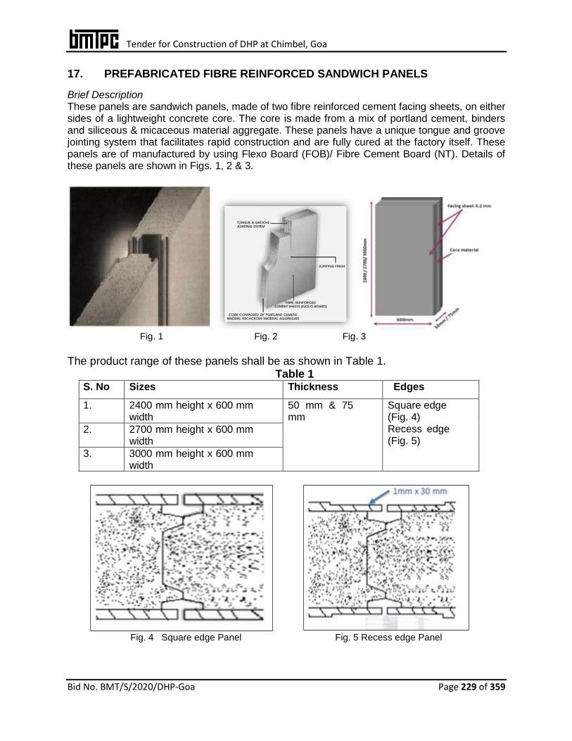
Tender for Construction of DHP at Chimbel, Goa
Bid No. BMT/S/2020/DHP-Goa Page 229 of 359
17. PREFABRICATED FIBRE REINFORCED SANDWICH PANELS
Brief Description These panels are sandwich panels, made of two fibre reinforced cement facing sheets, on either sides of a lightweight concrete core. The core is made from a mix of portland cement, binders and siliceous & micaceous material aggregate. These panels have a unique tongue and groove jointing system that facilitates rapid construction and are fully cured at the factory itself. These panels are of manufactured by using Flexo Board (FOB)/ Fibre Cement Board (NT). Details of these panels are shown in Figs. 1, 2 & 3.
Fig. 1 Fig. 2 Fig. 3
The product range of these panels shall be as shown in Table 1.
Table 1 S. No Sizes Thickness Edges
1. 2400 mm height x 600 mm width
50 mm & 75 mm
Square edge (Fig. 4) Recess edge (Fig. 5)
2. 2700 mm height x 600 mm width
3. 3000 mm height x 600 mm width
Fig. 4 Square edge Panel Fig. 5 Recess edge Panel

Tender for Construction of DHP at Chimbel, Goa
Bid No. BMT/S/2020/DHP-Goa Page 230 of 359
These panels may be used for the applications given in Table 2 Table 2
S. No Description Areas of Applications
1. Partitions
a. Full Height Residential, commercial, educational and
industrial buildings
b. Half Height
c. Jumbo Height
2. Prefab Structures (Single storey)
a. Load bearing b. Non-load bearing
Accommodation units, Site offices, Security & store rooms, Ware house/godowns, schools, Army barracks, low cost housing
3. Cladding Shopping malls, school/ College/ University, Duct covering, Site offices & Administration offices
4. Mezzanine Floor Industrial, Warehouses/godowns, Store rooms, Shopping malls & Showrooms
5. Boundary Walls Residential, Commercial, Govt./defence etc.
6. Fins / Vertical Lovers Residential & Commercial Buildings
7. Fire Separation walls Shopping malls, Hotels, Stair case enclosures etc.
Raw Materials
a. OPC 53 grade cement shall conform to IS 12269:2013 b. Fly ash shall conform to IS 3812 (Part 2):2003 c. Slag shall conform to IS 12089:1987 d. Quick lime shall conform to IS 712:1984 e. Anhydrous gypsum shall conform to IS 2547 (Part 1):1976 f. Fibre cement sheets shall conform to IS 13000: 1990 for asbestos cement sheets
and 14862: 2000 for fibre cement sheets Pulp (cotton rag) shall be as per manufacturer’s specifications
Performance Criteria The panels shall meet the performance criteria given in Table3:

Tender for Construction of DHP at Chimbel, Goa
Bid No. BMT/S/2020/DHP-Goa Page 231 of 359
Table 3 S. No
Properties Test Method Requirements *
50 mm thick 75 mm thick
FOB NT FOB NT
1. Weight (dry) (kg/m2) -- 39 38 54 51
2. Axial load (kN/m) Factor of safety = 2.5
53 50 83 65
3. Bending (kg/m2) (a) 1.5m span (b) 2.9m span
Factor of safety = 2.5
66 198
300
95 265
400
4. Flexural strength (kg/cm2)
IS 2380 (Part 4):1977
67 42 58 48
5. Compressive strength (kg/cm2)
Typical test results
30 -- 40 --
6. Thermal conductivity (W/mº.K)
IS 3346:1980/ BS 4370 (Part 2): 1993
0.22 0.16 0.21 0.17
7. Sound transmission class (dB)
IS 9901 (Part 3): 1981/IS 11050 (Part 1):1984
34 37 37 39
8. Fire resistance (minutes)
IS 3809:1979/ BS 476 (Part 20-22):1987
60 120 120 120
9. Surface spread of flame BS 476 (Part 7): 1997
Class I Class I
10. Fire propagation index (I)
BS 476 (Part 6): 1989
3.7 4.7 3.7 4.7
11. Ignitability BS 476 (Part 5): 1979
Class P (not easily ignitable)
Class P (not easily ignitable)
* The above requirements are the minimum values for the panels. Installation of Aerocon Panel Applications & Jointing Procedure Partition Walls Full height partition
Recess or square edge panels shall be used for full height partitions.
Floor plan shall be marked as per approved drawings.
The floor channels (F.C.) shall be cut as per required lengths and the ceiling shall be marked with plumb to floor channels and ceiling channels shall be fixed with self-expansion screws.
The floor channels shall be placed & fastened with self -expansion screws of size N 6 x 50 mm at every 600 mm centers on 50mm face of channel.
The height needs shall be checked for each individual panel before inserting, the same method shall be followed for all panels.
The floor channels, tongue and groove portion of panels shall be cleaned for firm fixing.
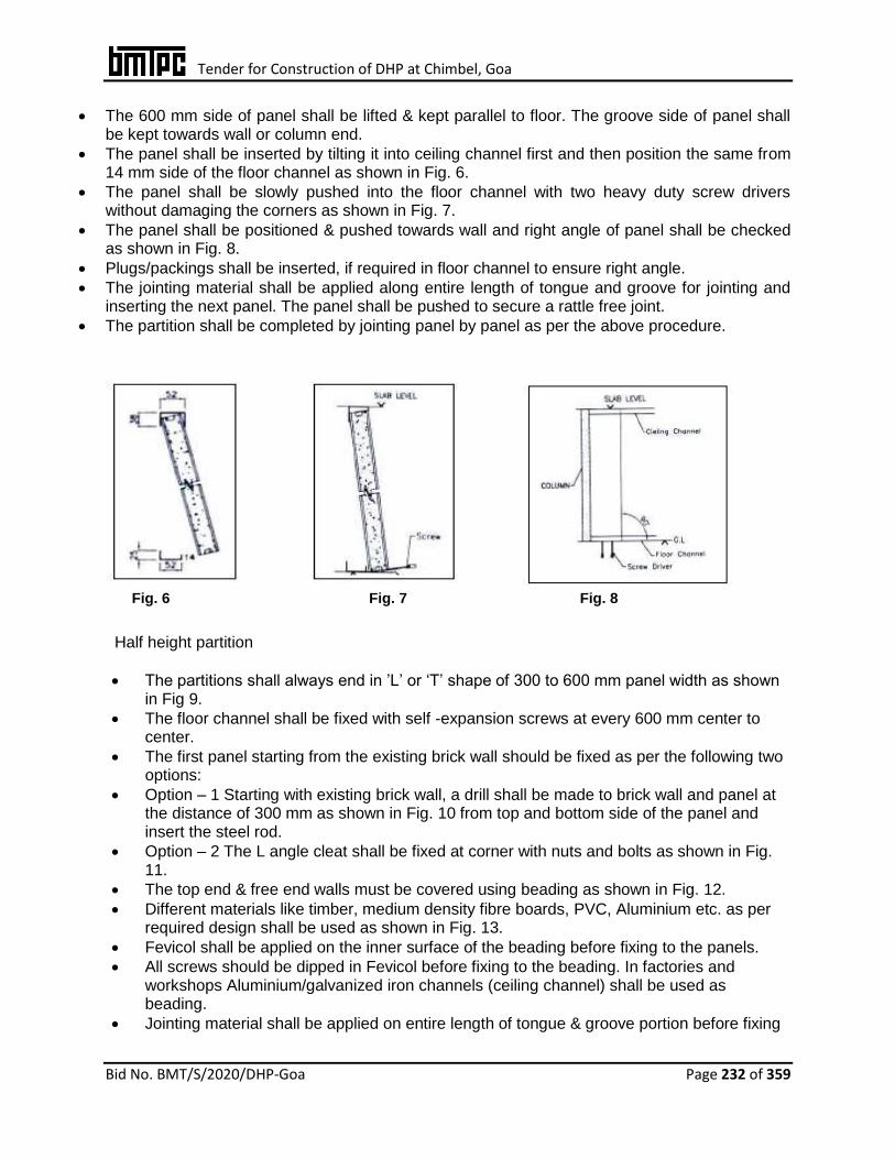
Tender for Construction of DHP at Chimbel, Goa
Bid No. BMT/S/2020/DHP-Goa Page 232 of 359
The 600 mm side of panel shall be lifted & kept parallel to floor. The groove side of panel shall be kept towards wall or column end.
The panel shall be inserted by tilting it into ceiling channel first and then position the same from 14 mm side of the floor channel as shown in Fig. 6.
The panel shall be slowly pushed into the floor channel with two heavy duty screw drivers without damaging the corners as shown in Fig. 7.
The panel shall be positioned & pushed towards wall and right angle of panel shall be checked as shown in Fig. 8.
Plugs/packings shall be inserted, if required in floor channel to ensure right angle.
The jointing material shall be applied along entire length of tongue and groove for jointing and inserting the next panel. The panel shall be pushed to secure a rattle free joint.
The partition shall be completed by jointing panel by panel as per the above procedure.
Fig. 6 Fig. 7 Fig. 8
Half height partition
The partitions shall always end in ’L’ or ‘T’ shape of 300 to 600 mm panel width as shown in Fig 9.
The floor channel shall be fixed with self -expansion screws at every 600 mm center to center.
The first panel starting from the existing brick wall should be fixed as per the following two options:
Option – 1 Starting with existing brick wall, a drill shall be made to brick wall and panel at the distance of 300 mm as shown in Fig. 10 from top and bottom side of the panel and insert the steel rod.
Option – 2 The L angle cleat shall be fixed at corner with nuts and bolts as shown in Fig. 11.
The top end & free end walls must be covered using beading as shown in Fig. 12.
Different materials like timber, medium density fibre boards, PVC, Aluminium etc. as per required design shall be used as shown in Fig. 13.
Fevicol shall be applied on the inner surface of the beading before fixing to the panels.
All screws should be dipped in Fevicol before fixing to the beading. In factories and workshops Aluminium/galvanized iron channels (ceiling channel) shall be used as beading.
Jointing material shall be applied on entire length of tongue & groove portion before fixing

Tender for Construction of DHP at Chimbel, Goa
Bid No. BMT/S/2020/DHP-Goa Page 233 of 359
panels to improve stability & prevent the lateral movement.
With this half height partition will be ready for finishing.
Fig. 9 Fig. 10 Option 1 Fig. 11 Option 2
Fig. 12 Fig. 13
Jumbo height partitions (above 3.0m)
Panel partition work can be done without steel frame up to 4.50 m height & 4.80 m width.
Frame work shall not be required for these type of partitions up to 4.5 m.
Panels shall be staggered for strength & rigidity as shown in Fig. 14. Height of the panels shall be decided accordingly.
Partition shall be supplied with top support, such as steel, concrete etc.
The floor & ceiling channel shall be fixed as per laid procedure.
For horizontal joining, the full length panel shall be fixed first and jointing material shall be applied in the groove portion.
Hexagonal PVC/wooden beading shall be placed on top groove of the 3 m panel before placing the 1.5 m panel and the same pushed into the ceiling channel as shown in Fig. 15.
The 1.5 m panel should come next in lower side and 3 meter panel in upper side & proceed in the similar way. The partition shall be completed by fixing panels one by one
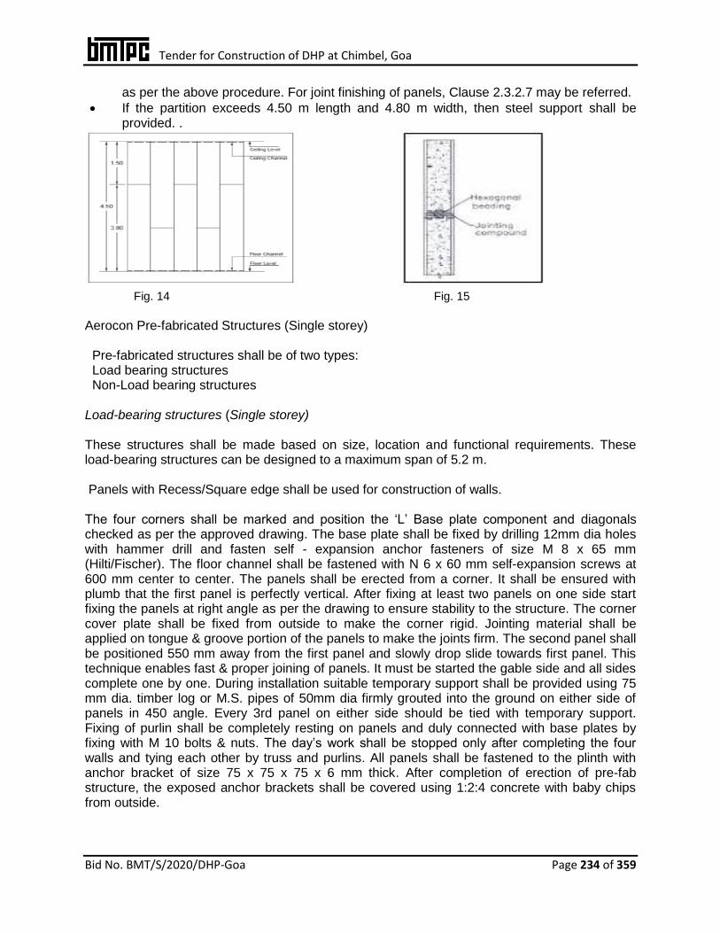
Tender for Construction of DHP at Chimbel, Goa
Bid No. BMT/S/2020/DHP-Goa Page 234 of 359
as per the above procedure. For joint finishing of panels, Clause 2.3.2.7 may be referred.
If the partition exceeds 4.50 m length and 4.80 m width, then steel support shall be provided. .
Fig. 14 Fig. 15
Aerocon Pre-fabricated Structures (Single storey) Pre-fabricated structures shall be of two types: Load bearing structures Non-Load bearing structures Load-bearing structures (Single storey) These structures shall be made based on size, location and functional requirements. These load-bearing structures can be designed to a maximum span of 5.2 m. Panels with Recess/Square edge shall be used for construction of walls. The four corners shall be marked and position the ‘L’ Base plate component and diagonals checked as per the approved drawing. The base plate shall be fixed by drilling 12mm dia holes with hammer drill and fasten self - expansion anchor fasteners of size M 8 x 65 mm (Hilti/Fischer). The floor channel shall be fastened with N 6 x 60 mm self-expansion screws at 600 mm center to center. The panels shall be erected from a corner. It shall be ensured with plumb that the first panel is perfectly vertical. After fixing at least two panels on one side start fixing the panels at right angle as per the drawing to ensure stability to the structure. The corner cover plate shall be fixed from outside to make the corner rigid. Jointing material shall be applied on tongue & groove portion of the panels to make the joints firm. The second panel shall be positioned 550 mm away from the first panel and slowly drop slide towards first panel. This technique enables fast & proper joining of panels. It must be started the gable side and all sides complete one by one. During installation suitable temporary support shall be provided using 75 mm dia. timber log or M.S. pipes of 50mm dia firmly grouted into the ground on either side of panels in 450 angle. Every 3rd panel on either side should be tied with temporary support. Fixing of purlin shall be completely resting on panels and duly connected with base plates by fixing with M 10 bolts & nuts. The day’s work shall be stopped only after completing the four walls and tying each other by truss and purlins. All panels shall be fastened to the plinth with anchor bracket of size 75 x 75 x 75 x 6 mm thick. After completion of erection of pre-fab structure, the exposed anchor brackets shall be covered using 1:2:4 concrete with baby chips from outside.
Tender for Construction of DHP at Chimbel, Goa
Bid No. BMT/S/2020/DHP-Goa Page 235 of 359
Corner Joints The ‘L’ and ‘T’ joints shall be made by fastening straight ends of the panels with self-expansion screws or 10 dia. x 100 mm long pin. The core of one panel shall be removed upto 15 mm depth in which the pin will be fastened only in the core, for filling grout cement. The panels shall be positioned in right angle and fastened with 150 mm long self-expansion screws at every 900 mm lengthwise using Hilti make or standard bolts 150 mm long galvanized/zinc coated threaded rod dipped in sodium silicate. The bore shall be filled with sodium silicate & flyash. 8 mm dia. holes shall be drilled at 600 mm centres height wise and 15 mm prepared groove shall be filled with grout cement using cocking gun. The facing of core (exposed part) shall be finished using silicon acrylic paste. In case of external application, the joints shall be covered with steel cover plate to protect the corner from knocks and other mechanical impacts. Lintel panels shall be firmly fixed with fastening the same to lateral panels with 12 mm dia. rods and cement grout. Minimum bearing of 150 mm shall be maintained on either side or for the gable walls where the height is more than 3 meters, panels shall be cut in triangular shape to fill the top gable. These triangular panels should be fixed from inner side by routing the face to the size 25 mm width x 25 mm depth and 200 mm length (100 mm in top panel and 100 mm in bottom panel) positioning the 200 mm long 12 dia. GI coated mild steel rod in the rout and filled with cement grout. Temporary bracing shall be fixed with timber/steel for one day and remove or putting of back to back G.I ceiling channel. Non-load bearing structures For non-load bearing structures, steel columns, trusses and purlins shall be designed as per soil condition and wind velocity. It shall be ensured that quality workmanship of the structure shall be checked at every stage of fabrication as per drawings and specification. It shall be ensured that the structure is complete in all respect before erection of the panels. The floor channel shall be fixed between two columns using self- expansion screws at every 600 mm centers, leaving gaps at door positions. Columns, trusses and purlins work shall be completed as per the approved drawing. Requisite number of panels shall be laid on the levelled ground with tongue & groove matching and a tie beam shall be provided from eave and gable walls to hold the panels. The panels shall be erected from a corner of a column and the panel erected as the load bearing structure procedure.
Doors and Windows Mild Steel, Wooden and Aluminium doors and windows can be fixed with Panel Electrical Wiring External wiring shall be done on the panels by using PVC caps/ pipes duly fixed to the surface. Concealed Wiring Electrical drawings shall always be referred before starting the work. Surface routing shall be done by cutting the facing sheet and removing core. Face chasing should be avoided for panels used in prefab structure external and load bearing especially the panels on which the trusses & purlins are fixed. Maximum depth of route shall be 50 percent of the thickness of material i.e. for 50 mm panel – 25 mm route and for 75 mm panel – 38 mm route. Switch box upto 40 mm depth shall be fixed in 50 mm panels and upto 60 mm depth in 75 mm panels. Load bearing walls

Tender for Construction of DHP at Chimbel, Goa
Bid No. BMT/S/2020/DHP-Goa Page 236 of 359
should not be routed horizontally. Horizontal face routing in non-load bearing walls shall be max. 300 mm from the joint. Jointing material shall be fixed in route and P.V.C. casing fixed, after setting electrical wiring. In case of mains or where multiple conducting is to be carried out, double skin partition wall shall be used. Plumbing Installation In Prefab structures, the toilets can be constructed with these panels. The required pipelines shall be fixed on the panel externally. If pipe lines need to be concealed, a false wall should be created with 50/75 mm panel to the required height on the internal side only. Water Closet (WC) shall be fixed with bolts & nuts. However, detailing needs to be worked out based on site conditions. The WC shall preferably be fixed on floor and bolted to the panel wall. The surface of the panel shall be treated with marble/ granite/ceramic/glazed tiles using ppropriate tile adhesive chemicals as per the procedure recommended by the tile adhesive manufacturer. It is recommended to use smaller tiles. Panel Jointing Procedure Aerocon Smart bond comprises of the following components: • Smartglu – Two part primary binder (powder & liquid): This glue is used for bonding as
well as a filling in solid wall panel installations. • Smartflex – Fixing paste: A ready to use paste to render a non-cracking, tensile but
elastic skin over the joint gaps. • Smartpoly – Self – saturating tape: Non-woven, self-saturating polyester tapes, ranging in
width from 16-80 mm, to reinforce the exposed skin of the joint. The wall shall be ready for whole surface primer & paint in normal way. Any kind of finishes for e.g. Painting, Tiling, Laminations etc. on the panels after joint finishing. Boundary Walls
• For construction of boundary walls with these panels, concrete or steel column shall be provided at every 2400 to 3000 mm distance based on site requirement.
• Panels shall be laid as per the sketch shown in Fig. • Jointing material shall be applied at the tongue and groove joint.

Tender for Construction of DHP at Chimbel, Goa
Bid No. BMT/S/2020/DHP-Goa Page 237 of 359
Fig. Boundary Wall details
Fins
Square edge panels ensure accurate dimensions and shall be fixed vertical and at required levels and heights with minimum scaffolding.
The maximum height of these louvers shall be limited to 3 meters.
It shall be ensured that the panel is properly inserted into the floor and ceiling channels.
The panels shall be secured with ‘L’ brackets and anchor fasteners.
Two cleats on either sides at roof level and two cleats at bottom level shall be fastened to secure the panel in position.
Details of fins are shown in Figs.
18. EPS CEMENT SANDWICH PANEL SYSTEM
Tender for Construction of DHP at Chimbel, Goa
Bid No. BMT/S/2020/DHP-Goa Page 238 of 359
1. Manufacturing & Fixing of EPS (Beads) based Cement Panel
Providing and fixing in position factory made EPS cement sandwich wall/roof/floor light weight solid core panels having thickness as per design and made of core material of EPS granule balls/beads(conforming to IS 4671:1984 and shall have density not less than 15kg per cum)adhesive, cement, sand, flyash and other bonding material in mortar state processed to form in a preset mould. The outer face on both sides of the panels shall be non asbestos fiber cement board conforming to IS 14862:2000 or Calcium silicate board conforming to EN 14306:2009 of 5mm thick each. Panel shall be laid on 6mm thick cement mortar (1 cement: 2 fine sand) mixed with chemical adhesive of 0.5kg per50kg of cement or shall be preferably fixed into 'C' channel made of 1.2mm thick MS plate screwed/ fastenened to the slab/column/beam etc. The panel shall fixed vertically with tongue and groove joint and horizontally locked with steel bar between each other and floors and filled with cement mortar and adhesive. Panels should be used as floor & roofing with additional structural support, steel or RCC depending upon the design. All the operation shall be completed in all respect as per drawings, manufacturers specifications and under the overall direction of Engineer-in-Charge
2. Steel Structural System
Steel structure frame as per design & conforming to IS: 800 shall be used in the construction. U type channels as per manufacturer’s specification should be used to hold the panels with the structure. Additional clips may be welded with the frame pillars and beams to hold the U channel firmly with the pillars/beans and floor, to ensure structural integrity. PU glue may be applied to hold the panels firmly.
All relevant Indian Standards/ requirements of NBC shall be conformed for materials, design fabrication and erection.
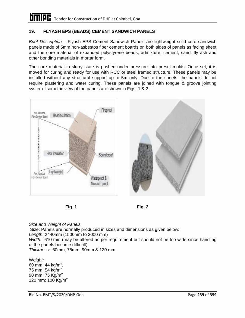
Tender for Construction of DHP at Chimbel, Goa
Bid No. BMT/S/2020/DHP-Goa Page 239 of 359
19. FLYASH EPS (BEADS) CEMENT SANDWICH PANELS Brief Description – Flyash EPS Cement Sandwich Panels are lightweight solid core sandwich
panels made of 5mm non-asbestos fiber cement boards on both sides of panels as facing sheet
and the core material of expanded polystyrene beads, admixture, cement, sand, fly ash and
other bonding materials in mortar form.
The core material in slurry state is pushed under pressure into preset molds. Once set, it is
moved for curing and ready for use with RCC or steel framed structure. These panels may be
installed without any structural support up to 5m only. Due to the sheets, the panels do not
require plastering and water curing. These panels are joined with tongue & groove jointing
system. Isometric view of the panels are shown in Figs. 1 & 2.
Fig. 1 Fig. 2
Size and Weight of Panels Size: Panels are normally produced in sizes and dimensions as given below: Length: 2440mm (1500mm to 3000 mm) Width: 610 mm (may be altered as per requirement but should not be too wide since handling of the panels become difficult) Thickness: 60mm, 75mm, 90mm & 120 mm. Weight: 60 mm: 44 kg/m2, 75 mm: 54 kg/m2 90 mm: 75 Kg/m2 120 mm: 100 Kg/m2

Tender for Construction of DHP at Chimbel, Goa
Bid No. BMT/S/2020/DHP-Goa Page 240 of 359
Specifications
Raw Materials
i) OPC 43/53 grade cement shall conform to IS 8112:2013/ 12269:2013. ii) Fly ash shall conform to IS 3812 (Part 1):2013. iii) EPS beads shall conform to IS 4671:1984 and shall have density not less than 15 kg/m3. iv) Fibre cement board shall be of Type A & category C as per IS 14862:2000. v) Calcium silicon board shall conform to EN 14306: 2009. vi) Fine sand & coarse aggregate shall conform to IS 383:2016. vii) MS-C Channel shall be manufactured from pre-galvanized high tensile steel conforming
to IS 277:2018. viii) Adhesive & Bonding agents shall conform to the manufacturer specifications.
‘C’ Section For 60 mm panel Size for bottom: (A) 28mm x (B) 61mm x (C) 18mm Size for top: (A) 28mm x (B) 61mm x (C) 28mm For 75 mm panel Size for bottom: (A) 28mm x (B) 76mm x (C) 18mm Size for top: (A) 28mm x (B) 76mm x (C) 28mm For 90 mm panel Size for bottom: (A) 28mm x (B) 91mm x (C) 18mm Fig. 3 Size for top: (A) 28 mm x (B) 91 mm x (C) 28 mm For 120 mm panel Size for bottom: (A) 28mm x (B) 121mm x (C) 18mm Size for top: (A) 28mm x (B) 121mm x (C) 28mm Details of C channels are shown in Figs. 3 & 4.
Fig. 4
Design Parameters
The EPS Cement panels are produced using cement, EPS and fly ash / sand along with bonding agents to form walling material. The system may be used as an alternate solution to a building designed using conventional brickwork masonry wall.
The system is intended for use where Architectural drawings are available and satisfy the various requirements. The Architect and Engineer designer team of the concerned developer/ owner (client) is responsible for the drawings and overall building design to comply with the various regulatory requirements applicable to the area.
The design assumptions, detailed calculations, references to necessary and detailed design drawings shall be jointly made and the structural design calculations should clearly demonstrate structural integrity and stability including connection details.
Installation of panels & Jointing Procedure
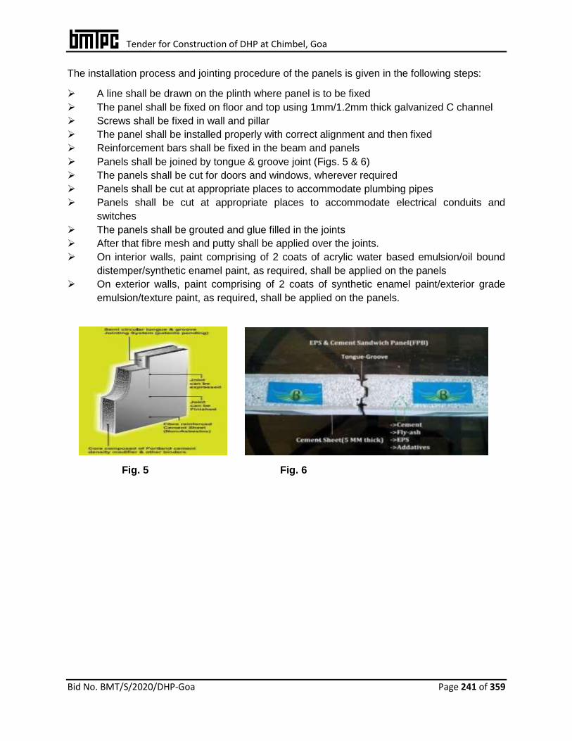
Tender for Construction of DHP at Chimbel, Goa
Bid No. BMT/S/2020/DHP-Goa Page 241 of 359
The installation process and jointing procedure of the panels is given in the following steps:
A line shall be drawn on the plinth where panel is to be fixed
The panel shall be fixed on floor and top using 1mm/1.2mm thick galvanized C channel
Screws shall be fixed in wall and pillar
The panel shall be installed properly with correct alignment and then fixed
Reinforcement bars shall be fixed in the beam and panels
Panels shall be joined by tongue & groove joint (Figs. 5 & 6)
The panels shall be cut for doors and windows, wherever required
Panels shall be cut at appropriate places to accommodate plumbing pipes
Panels shall be cut at appropriate places to accommodate electrical conduits and
switches
The panels shall be grouted and glue filled in the joints
After that fibre mesh and putty shall be applied over the joints.
On interior walls, paint comprising of 2 coats of acrylic water based emulsion/oil bound
distemper/synthetic enamel paint, as required, shall be applied on the panels
On exterior walls, paint comprising of 2 coats of synthetic enamel paint/exterior grade
emulsion/texture paint, as required, shall be applied on the panels.
Fig. 5 Fig. 6
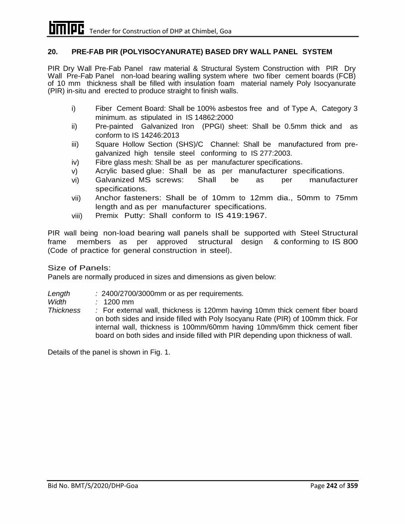
Tender for Construction of DHP at Chimbel, Goa
Bid No. BMT/S/2020/DHP-Goa Page 242 of 359
20. PRE-FAB PIR (POLYISOCYANURATE) BASED DRY WALL PANEL SYSTEM
PIR Dry Wall Pre-Fab Panel raw material & Structural System Construction with PIR Dry Wall Pre-Fab Panel non-load bearing walling system where two fiber cement boards (FCB) of 10 mm thickness shall be filled with insulation foam material namely Poly Isocyanurate (PIR) in-situ and erected to produce straight to finish walls.
i) Fiber Cement Board: Shall be 100% asbestos free and of Type A, Category 3
minimum. as stipulated in IS 14862:2000
ii) Pre-painted Galvanized Iron (PPGI) sheet: Shall be 0.5mm thick and as
conform to IS 14246:2013
iii) Square Hollow Section (SHS)/C Channel: Shall be manufactured from pre-
galvanized high tensile steel conforming to IS 277:2003.
iv) Fibre glass mesh: Shall be as per manufacturer specifications.
v) Acrylic based glue: Shall be as per manufacturer specifications.
vi) Galvanized MS screws: Shall be as per manufacturer
specifications.
vii) Anchor fasteners: Shall be of 10mm to 12mm dia., 50mm to 75mm
length and as per manufacturer specifications.
viii) Premix Putty: Shall conform to IS 419:1967.
PIR wall being non-load bearing wall panels shall be supported with Steel Structural
frame members as per approved structural design & conforming to IS 800
(Code of practice for general construction in steel).
Size of Panels:
Panels are normally produced in sizes and dimensions as given below: Length : 2400/2700/3000mm or as per requirements. Width : 1200 mm Thickness : For external wall, thickness is 120mm having 10mm thick cement fiber board
on both sides and inside filled with Poly Isocyanu Rate (PIR) of 100mm thick. For internal wall, thickness is 100mm/60mm having 10mm/6mm thick cement fiber board on both sides and inside filled with PIR depending upon thickness of wall.
Details of the panel is shown in Fig. 1.
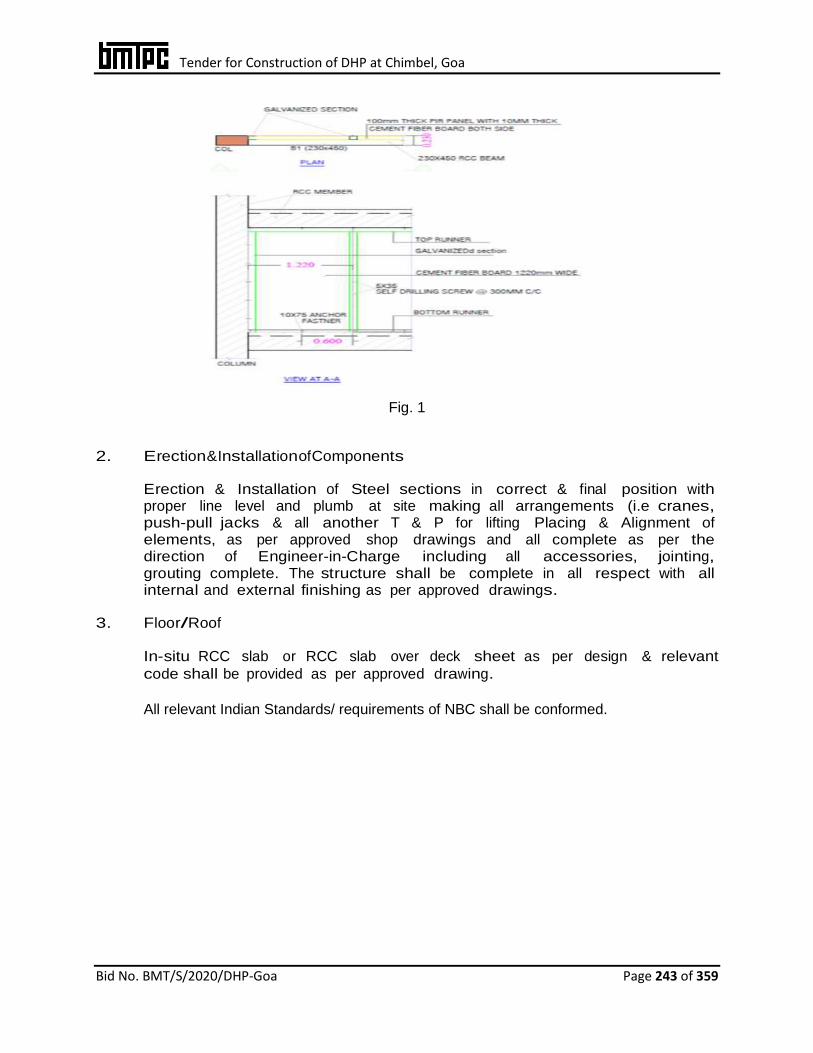
Tender for Construction of DHP at Chimbel, Goa
Bid No. BMT/S/2020/DHP-Goa Page 243 of 359
Fig. 1
2. Erection & Installation of Components
Erection & Installation of Steel sections in correct & final position with proper line level and plumb at site making all arrangements (i.e cranes, push-pull jacks & all another T & P for lifting Placing & Alignment of elements, as per approved shop drawings and all complete as per the direction of Engineer-in-Charge including all accessories, jointing, grouting complete. The structure shall be complete in all respect with all internal and external finishing as per approved drawings.
3. Floor/Roof
In-situ RCC slab or RCC slab over deck sheet as per design & relevant
code shall be provided as per approved drawing.
All relevant Indian Standards/ requirements of NBC shall be conformed.

Tender for Construction of DHP at Chimbel, Goa
Bid No. BMT/S/2020/DHP-Goa Page 244 of 359
21. BAUPANEL SYSTEM
The technical specifications would be entirely based on design parameters, however, the minimum specification as given below is recommended to be adhered to; 1. Specifications of Raw Materials for EPS Panel i) Zinc Coated cold drawn Steel Wire – Shall be of 2.5/3.0 mm dia and zinc coating
galvanizing shall be of 60 gm/m2 ± 5 gm/m2
Mechanical characteristics Yield stress : > 600 N/mm2 Breaking load : > 680 N/mm2 Elongation : > 8%
Chemical characteristics % C : < 0.24 % P : < 0.055 % S : < 0.055 % Ceq : < 0.52 ii) Expanded Polystyrene – Self-extinguishing type EPS 80 in accordance to UNI
EN 13163:2013 (IS 4671: 1984) having density not less than 15 kg/m3
2. EPS Panels for wall
Walling shall be completed using factory made Expanded Polystyrene Core Panel (EPS) based electro welded wire mesh 3D panels manufactured using
the specified EPS and Cold drawn wire and sprayed structural plaster. The specification of panel shall not be less than the values given in fig. 1 & 2 below. Both the outer faces of the panel shall be finished by applying the
layer of minimum 35 mm thick cement mortar 1:3 {1 cement: 3 coarse sand (not having more than 40% stone chips of size upto 6 mm)} with the help of
shotcreting / guniting equipment etc at a pressure not less than 1 bar (100Kn/m2) and both surfaces finished with trowel. The composition of spray/ mortar shall be such as to give minimum characteristic strength of 25
N/mm2.
The maximum w/c ratio shall be 0.45. The thickness of the sprayed concrete & EPS wall shall be based on design requirements.

Tender for Construction of DHP at Chimbel, Goa
Bid No. BMT/S/2020/DHP-Goa Page 245 of 359
S
i
n
g
l
e
p
a
n
e
l
for structural uses
Fig.1
Single panel for internal partition and insulation
Longitudinal wire
Min 2.5 mm ø spaced @ 80 mm (Max.)
Typical Drawing
Transverse wire
Min 2.5 mm ø spaced @ 75 mm (Max.)
Cross steel wire 3.0 mm ø approx 45 nos. / m2
polystyrene Core
Density > 15 Kg/m3,
Thickness 40 mm to 320 mm
Finished Masonry
Min 90 mm
Longitudinal wire Min 2.5 mm ø spaced @ 70 mm (Max.)
Typical Drawing
Transverse wire Min 2.5 mm ø spaced @ 70 mm (Max.)
Cross steel wire Min 3.0 mm ø approx 68 nos. / m2
polystyrene Core Density >15 Kg/m3,
Thickness not less than 80 mm
Finished Masonry
Not less than 150 mm thick
Grade of Shotcrete
Minimum M-25

Tender for Construction of DHP at Chimbel, Goa
Bid No. BMT/S/2020/DHP-Goa Page 246 of 359
3. Staircase panel
The EPS panel based staircase would be preferred as per minimum
specification given in Fig.3. However, the Agency can propose for construction of staircase in RCC or steel frame based staircase for
approach on all floors up to terrace floor. The concrete thickness shall be as per as per design requirement & spary/mortar shall be minimum 30
mm.
Fig 3
4. Flooring & Roofing
Intermediate floor shall be composite EPS as per specification and shall be designed for
combined effect of dead load, imposed load & other loading conditions. The
specification of panel shall not be less than the values given in fig. 4 below
Single Panel for horizontal structure for floor/ roof
Longitudinal wire Min 2.5 mm ø spaced @ 80 mm
Transverse wire Min 2.5 mm ø spaced @ 75 mm
Cross steel wire Min 3.0 mm ø approx 68 nos. / m2
polystyrene Core Density Min15 Kg/m3
Thickness Min 80 mm
Finished Masonry
Min 160 mm thick
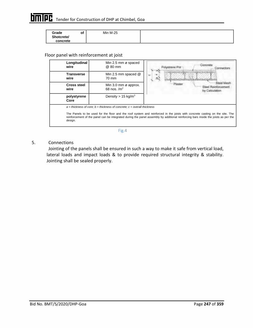
Tender for Construction of DHP at Chimbel, Goa
Bid No. BMT/S/2020/DHP-Goa Page 247 of 359
Grade of
Shotcrete/ concrete
Min M-25
Floor panel with reinforcement at joist
Longitudinal wire
Min 2.5 mm ø spaced @ 80 mm
Transverse wire
Min 2.5 mm spaced @ 70 mm
Cross steel wire
Min 3.0 mm ø approx. 68 nos. /m2
polystyrene Core
Density > 15 kg/m3
a = thickness of core; b = thickness of concrete; c = overall thickness
The Panels to be used for the floor and the roof system and reinforced in the joists with concrete casting on the site. The reinforcement of the panel can be integrated during the panel assembly by additional reinforcing bars inside the joists as per the design.
Fig.4
5. Connections Jointing of the panels shall be ensured in such a way to make it safe from vertical load,
lateral loads and impact loads & to provide required structural integrity & stability. Jointing shall be sealed properly.

Tender for Construction of DHP at Chimbel, Goa
Bid No. BMT/S/2020/DHP-Goa Page 248 of 359
22. V-INFILL WALL (LIGHT WEIGHT EPS WALL). Brief Description
V-Infill Wall is an innovative emerging building and construction technology using factory made 8/10mm fibre cement boards (V-board) on either side of GI studs and erected to produce straight to finish walls which are filled with light weight concrete made of EPS, cement, sand and additive. The system may be integrated with conventional column and beam for pre-engineered buildings. The walls may be used as partition walls for external and internal applications.
The GI studs are “C” cross-section with built in notch, slots, service holes etc. fixed with floor and ceiling channels using anchor fasteners at spacing of 300mm c/c. Provisions for doors, windows, ventilators and other cutouts as required shall be incorporated. Electrical and plumbing pipes/conduits shall be provided in the service holes of studs before concreting is done.
The firm is also the manufacturer of fibre cement board branded as Vpremium board, G I studs branded as Vnext, Visaka additive and Visaka bond liquid which are used in producing the V-Infill Wall.
Fibre Cement Board G.I Stud
Light Weight Concret
Fig. 1
Types of Walls
There are two types of V-Infill Walls as per details given below
1. 88 mm thick wall consists of 8mm thick board of size 1.22m x 2.44m on either side of 70mm G.I studs and screw of 8g x 25mm length.
2. 150mm thick wall consists of 10mm thick board of size 1.22m x 2.44m on either side of 130mm G.I studs and screw of 10g x 32mm length.
Size of Walls:

Tender for Construction of DHP at Chimbel, Goa
Bid No. BMT/S/2020/DHP-Goa Page 249 of 359
Walls are made in-situ so there is no standard size of walls. However, height and length of wall shall not be more than 3m and 6m respectively. Details of V-Infill Wall is shown in fig. 2
Fig 2
Typical Activity for construction using V-Infill Wall is as follow After laying the foundation following Construction Activities are done 1) Erection of frame work with GI studs and channel 2) Placing 10mm & 8mm dia TMT bars as specified 3) Providing electrical and plumbing conduits 4) Fixing of fibre cement board on both sides of frame 5) V-Infill Concrete mixing and pumping 6) Finishing of joints with jointing powder mixed with fevicol.

Tender for Construction of DHP at Chimbel, Goa
Bid No. BMT/S/2020/DHP-Goa Page 250 of 359
Erection of V-Infill Wall: Line marking shall be as per wall layout with chalk or pencil.The framing section shall be cold form “C’ type of 0.55 mm to 0.60 mm thickness in required length as per structural design requirements, duly punched with dimple slots at required locations as per approved drawings. The slots shall be along center line of the web and shall be placed at 250 mm min. away from both edges of the member. The studs shall be of specified dimensions and fastened with GI channel to both top and bottom slab. Frames shall be assembled together to fabricate structures using anchor fastener of 6mm dia. at spacing of 400mm c/c.. The V-Infill Wall frames shall be connected by using special screws which shall conform to ASTM C 1513. After fixing of floor and ceiling channels, GI “C” studs (70mm) shall be placed vertically with a minimum gap of 12mm to 20mm from top and bottom of floor channel webs. They shall be fixed together with self-driven metal screws at spacing of 300mm c/c. For provision of doors, windows and other openings, additional studs shall be provided. Electrical conduits and plumbing pipes shall be placed through the slots/holes provided in the web of the studs. Electrical boxes and boards should be fixed and embedded in EPS concrete properly. Before fixing of cement fibre board, adhesive (liquid PU) shall be applied on flanges of GI studs. After that Vpremium board of thickness 8/10 mm shall be fixed horizontally on both sides of the frame work up to 1200mm height using self-driven screws of 8g x 32mm at 200mm spacing. Light weight and free flow concrete prepared by mixing cement, coarse sand, EPS beads, water and additives in specified ratio shall be poured into V-infill walls Prior to start concrete pour, it must be re-checked to ensure that all members are properly aligned and plumbed. The concrete specified shall be highly workable, free flowing mix poured from the top into the cavities using a small hose for pumping. For small building construction, concrete can be poured manually using a funnel. Filling the cavities with concrete shall be done in two layers of 600mm height with an interval of 2 to 3 hours between each layer. Needle vibrator or rubber mallet may be used for equal distribution and compaction of concrete inside the cavities. Pouring shall be continued in the upper portion in a similar manner. Top portion shall be filled after cutting 150mm x 150mm U shape slot in the board. After walls are completely filled and mix dried, joint treatment shall be done using fibre mesh tape and putty mixed with binder (fevicol) in specified ratio on both exterior and interior joints. One coat of putty shall be applied to close the joint, then second coat shall be applied in order to flush recessed part. Mesh tape shall be sandwiched between first & second coats to have a hold over the wall.
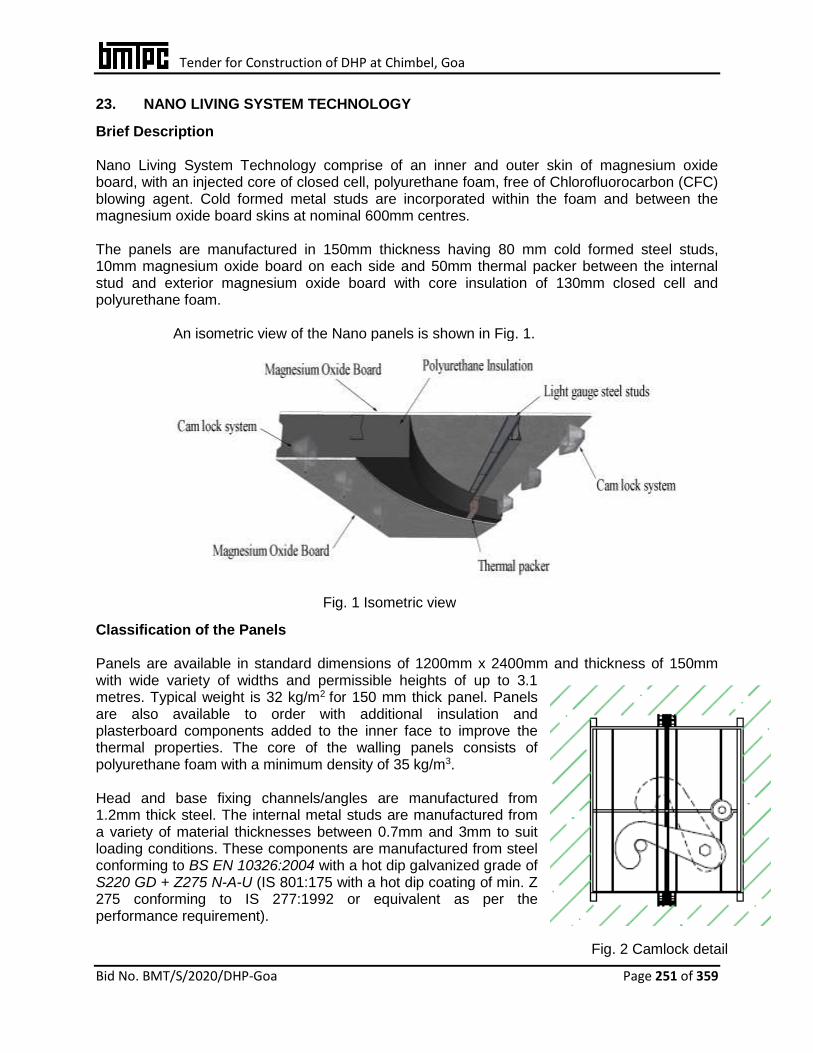
Tender for Construction of DHP at Chimbel, Goa
Bid No. BMT/S/2020/DHP-Goa Page 251 of 359
23. NANO LIVING SYSTEM TECHNOLOGY
Brief Description Nano Living System Technology comprise of an inner and outer skin of magnesium oxide board, with an injected core of closed cell, polyurethane foam, free of Chlorofluorocarbon (CFC) blowing agent. Cold formed metal studs are incorporated within the foam and between the magnesium oxide board skins at nominal 600mm centres. The panels are manufactured in 150mm thickness having 80 mm cold formed steel studs, 10mm magnesium oxide board on each side and 50mm thermal packer between the internal stud and exterior magnesium oxide board with core insulation of 130mm closed cell and polyurethane foam.
An isometric view of the Nano panels is shown in Fig. 1.
Fig. 1 Isometric view
Classification of the Panels Panels are available in standard dimensions of 1200mm x 2400mm and thickness of 150mm with wide variety of widths and permissible heights of up to 3.1 metres. Typical weight is 32 kg/m2 for 150 mm thick panel. Panels are also available to order with additional insulation and plasterboard components added to the inner face to improve the thermal properties. The core of the walling panels consists of polyurethane foam with a minimum density of 35 kg/m3. Head and base fixing channels/angles are manufactured from 1.2mm thick steel. The internal metal studs are manufactured from a variety of material thicknesses between 0.7mm and 3mm to suit loading conditions. These components are manufactured from steel conforming to BS EN 10326:2004 with a hot dip galvanized grade of S220 GD + Z275 N-A-U (IS 801:175 with a hot dip coating of min. Z 275 conforming to IS 277:1992 or equivalent as per the performance requirement).
Fig. 2 Camlock detail
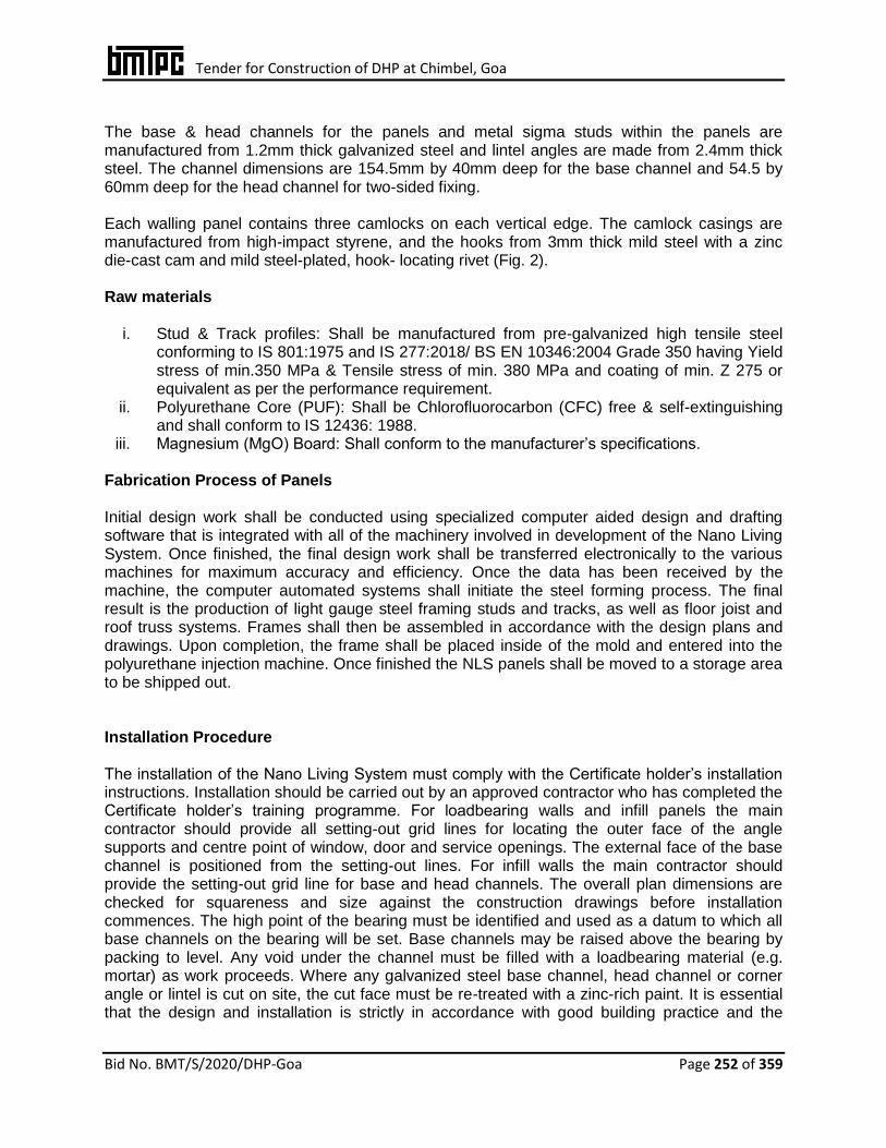
Tender for Construction of DHP at Chimbel, Goa
Bid No. BMT/S/2020/DHP-Goa Page 252 of 359
The base & head channels for the panels and metal sigma studs within the panels are manufactured from 1.2mm thick galvanized steel and lintel angles are made from 2.4mm thick steel. The channel dimensions are 154.5mm by 40mm deep for the base channel and 54.5 by 60mm deep for the head channel for two-sided fixing.
Each walling panel contains three camlocks on each vertical edge. The camlock casings are manufactured from high-impact styrene, and the hooks from 3mm thick mild steel with a zinc die-cast cam and mild steel-plated, hook- locating rivet (Fig. 2). Raw materials
i. Stud & Track profiles: Shall be manufactured from pre-galvanized high tensile steel conforming to IS 801:1975 and IS 277:2018/ BS EN 10346:2004 Grade 350 having Yield stress of min.350 MPa & Tensile stress of min. 380 MPa and coating of min. Z 275 or equivalent as per the performance requirement.
ii. Polyurethane Core (PUF): Shall be Chlorofluorocarbon (CFC) free & self-extinguishing and shall conform to IS 12436: 1988.
iii. Magnesium (MgO) Board: Shall conform to the manufacturer’s specifications.
Fabrication Process of Panels Initial design work shall be conducted using specialized computer aided design and drafting software that is integrated with all of the machinery involved in development of the Nano Living System. Once finished, the final design work shall be transferred electronically to the various machines for maximum accuracy and efficiency. Once the data has been received by the machine, the computer automated systems shall initiate the steel forming process. The final result is the production of light gauge steel framing studs and tracks, as well as floor joist and roof truss systems. Frames shall then be assembled in accordance with the design plans and drawings. Upon completion, the frame shall be placed inside of the mold and entered into the polyurethane injection machine. Once finished the NLS panels shall be moved to a storage area to be shipped out. Installation Procedure The installation of the Nano Living System must comply with the Certificate holder’s installation instructions. Installation should be carried out by an approved contractor who has completed the Certificate holder’s training programme. For loadbearing walls and infill panels the main contractor should provide all setting-out grid lines for locating the outer face of the angle supports and centre point of window, door and service openings. The external face of the base channel is positioned from the setting-out lines. For infill walls the main contractor should provide the setting-out grid line for base and head channels. The overall plan dimensions are checked for squareness and size against the construction drawings before installation commences. The high point of the bearing must be identified and used as a datum to which all base channels on the bearing will be set. Base channels may be raised above the bearing by packing to level. Any void under the channel must be filled with a loadbearing material (e.g. mortar) as work proceeds. Where any galvanized steel base channel, head channel or corner angle or lintel is cut on site, the cut face must be re-treated with a zinc-rich paint. It is essential that the design and installation is strictly in accordance with good building practice and the
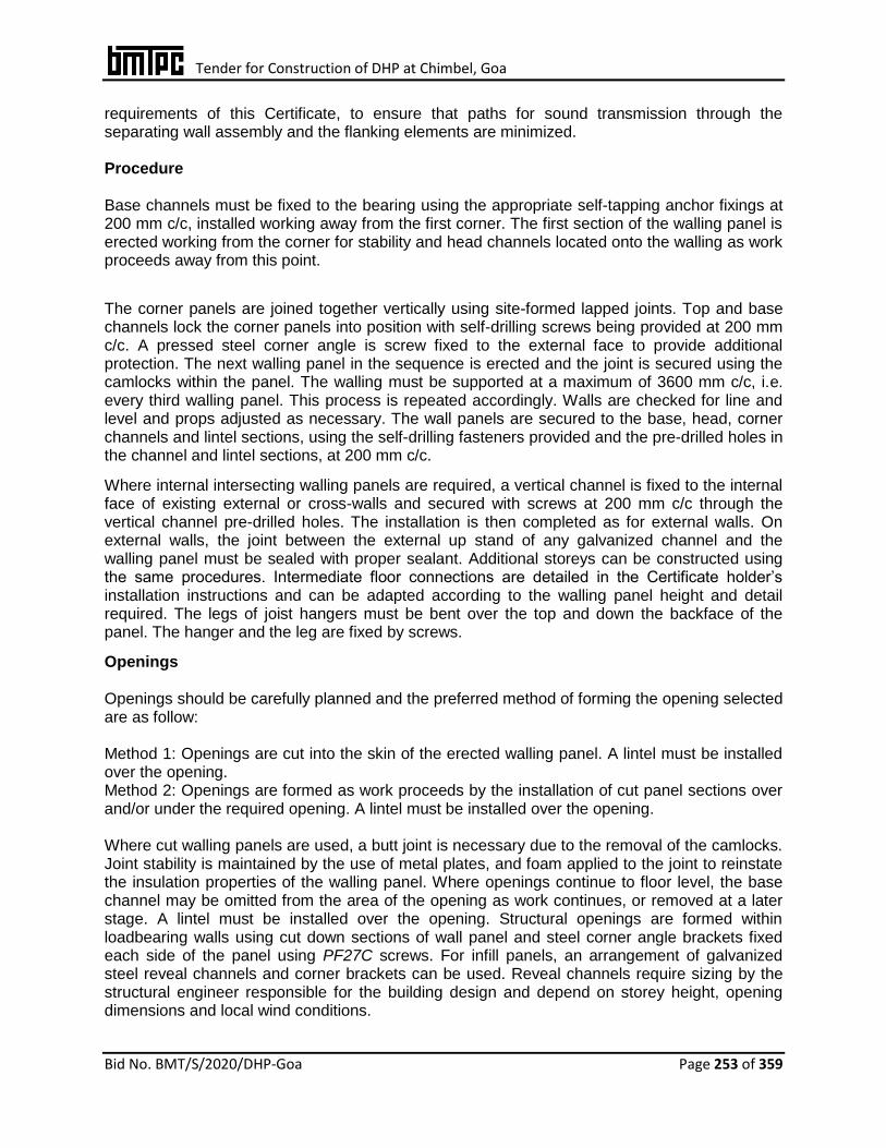
Tender for Construction of DHP at Chimbel, Goa
Bid No. BMT/S/2020/DHP-Goa Page 253 of 359
requirements of this Certificate, to ensure that paths for sound transmission through the separating wall assembly and the flanking elements are minimized. Procedure Base channels must be fixed to the bearing using the appropriate self-tapping anchor fixings at 200 mm c/c, installed working away from the first corner. The first section of the walling panel is erected working from the corner for stability and head channels located onto the walling as work proceeds away from this point.
The corner panels are joined together vertically using site-formed lapped joints. Top and base channels lock the corner panels into position with self-drilling screws being provided at 200 mm c/c. A pressed steel corner angle is screw fixed to the external face to provide additional protection. The next walling panel in the sequence is erected and the joint is secured using the camlocks within the panel. The walling must be supported at a maximum of 3600 mm c/c, i.e. every third walling panel. This process is repeated accordingly. Walls are checked for line and level and props adjusted as necessary. The wall panels are secured to the base, head, corner channels and lintel sections, using the self-drilling fasteners provided and the pre-drilled holes in the channel and lintel sections, at 200 mm c/c.
Where internal intersecting walling panels are required, a vertical channel is fixed to the internal face of existing external or cross-walls and secured with screws at 200 mm c/c through the vertical channel pre-drilled holes. The installation is then completed as for external walls. On external walls, the joint between the external up stand of any galvanized channel and the walling panel must be sealed with proper sealant. Additional storeys can be constructed using the same procedures. Intermediate floor connections are detailed in the Certificate holder’s installation instructions and can be adapted according to the walling panel height and detail required. The legs of joist hangers must be bent over the top and down the backface of the panel. The hanger and the leg are fixed by screws.
Openings Openings should be carefully planned and the preferred method of forming the opening selected are as follow: Method 1: Openings are cut into the skin of the erected walling panel. A lintel must be installed over the opening. Method 2: Openings are formed as work proceeds by the installation of cut panel sections over and/or under the required opening. A lintel must be installed over the opening. Where cut walling panels are used, a butt joint is necessary due to the removal of the camlocks. Joint stability is maintained by the use of metal plates, and foam applied to the joint to reinstate the insulation properties of the walling panel. Where openings continue to floor level, the base channel may be omitted from the area of the opening as work continues, or removed at a later stage. A lintel must be installed over the opening. Structural openings are formed within loadbearing walls using cut down sections of wall panel and steel corner angle brackets fixed each side of the panel using PF27C screws. For infill panels, an arrangement of galvanized steel reveal channels and corner brackets can be used. Reveal channels require sizing by the structural engineer responsible for the building design and depend on storey height, opening dimensions and local wind conditions.
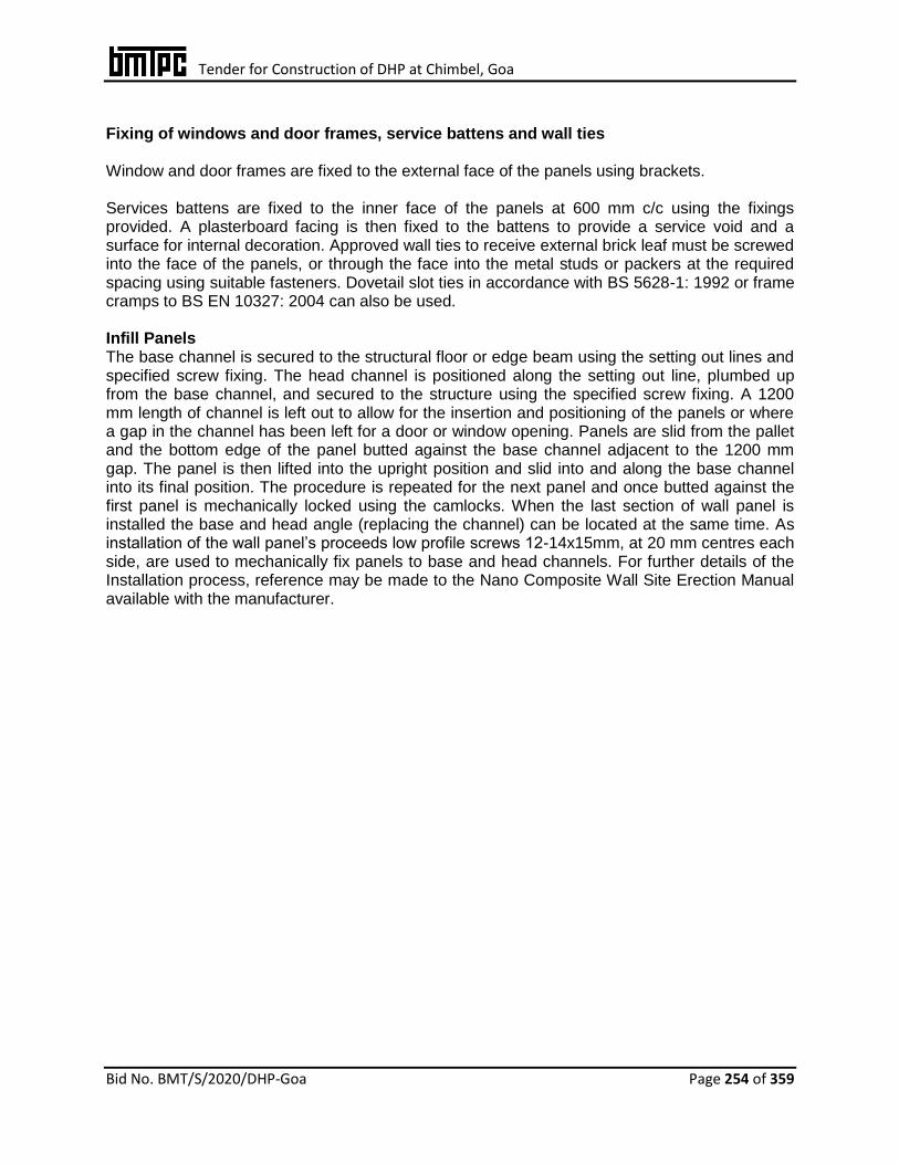
Tender for Construction of DHP at Chimbel, Goa
Bid No. BMT/S/2020/DHP-Goa Page 254 of 359
Fixing of windows and door frames, service battens and wall ties Window and door frames are fixed to the external face of the panels using brackets. Services battens are fixed to the inner face of the panels at 600 mm c/c using the fixings provided. A plasterboard facing is then fixed to the battens to provide a service void and a surface for internal decoration. Approved wall ties to receive external brick leaf must be screwed into the face of the panels, or through the face into the metal studs or packers at the required spacing using suitable fasteners. Dovetail slot ties in accordance with BS 5628-1: 1992 or frame cramps to BS EN 10327: 2004 can also be used. Infill Panels The base channel is secured to the structural floor or edge beam using the setting out lines and specified screw fixing. The head channel is positioned along the setting out line, plumbed up from the base channel, and secured to the structure using the specified screw fixing. A 1200 mm length of channel is left out to allow for the insertion and positioning of the panels or where a gap in the channel has been left for a door or window opening. Panels are slid from the pallet and the bottom edge of the panel butted against the base channel adjacent to the 1200 mm gap. The panel is then lifted into the upright position and slid into and along the base channel into its final position. The procedure is repeated for the next panel and once butted against the first panel is mechanically locked using the camlocks. When the last section of wall panel is installed the base and head angle (replacing the channel) can be located at the same time. As installation of the wall panel’s proceeds low profile screws 12-14x15mm, at 20 mm centres each side, are used to mechanically fix panels to base and head channels. For further details of the Installation process, reference may be made to the Nano Composite Wall Site Erection Manual available with the manufacturer.
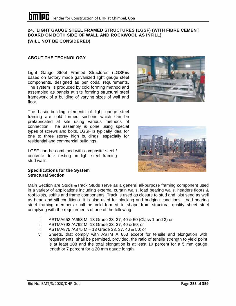
Tender for Construction of DHP at Chimbel, Goa
Bid No. BMT/S/2020/DHP-Goa Page 255 of 359
24. LIGHT GAUGE STEEL FRAMED STRUCTURES (LGSF) (WITH FIBRE CEMENT BOARD ON BOTH SIDE OF WALL AND ROCKWOOL AS INFILL)
(WILL NOT BE CONSIDERED)
ABOUT THE TECHNOLOGY
Light Gauge Steel Framed Structures (LGSF)is based on factory made galvanized light gauge steel components, designed as per codal requirements. The system is produced by cold forming method and assembled as panels at site forming structural steel framework of a building of varying sizes of wall and floor. The basic building elements of light gauge steel framing are cold formed sections which can be prefabricated at site using various methods of connection. The assembly is done using special types of screws and bolts. LGSF is typically ideal for one to three storey high buildings, especially for residential and commercial buildings. LGSF can be combined with composite steel / concrete deck resting on light steel framing stud walls. Specifications for the System Structural Section
Main Section are Studs &Track Studs serve as a general all-purpose framing component used in a variety of applications including external curtain walls, load bearing walls, headers floors & roof joists, soffits and frame components. Track is used as closure to stud and joist send as well as head and sill conditions. It is also used for blocking and bridging conditions. Load bearing steel framing members shall be cold–formed to shape from structural quality sheet steel complying with the requirements of one of the following:
i. ASTMA653 /A653 M -13 Grade 33, 37, 40 & 50 (Class 1 and 3) or ii. ASTMA792 /A792 M -13 Grade 33, 37, 40 & 50; or iii. ASTMA875 /A875 M – 13 Grade 33, 37, 40 & 50; or iv. Sheets, that comply with ASTM A 653 except for tensile and elongation with
requirements, shall be permitted, provided, the ratio of tensile strength to yield point is at least 108 and the total elongation is at least 10 percent for a 5 mm gauge length or 7 percent for a 20 mm gauge length.
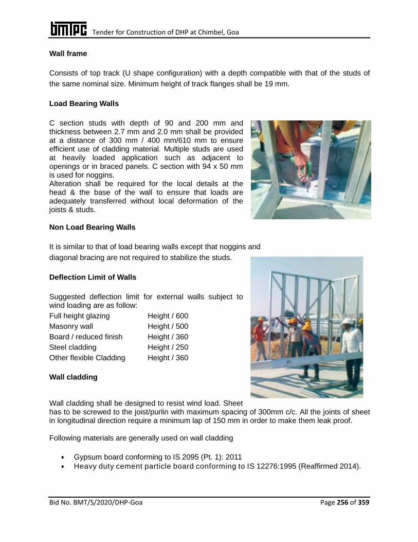
Tender for Construction of DHP at Chimbel, Goa
Bid No. BMT/S/2020/DHP-Goa Page 256 of 359
Wall frame Consists of top track (U shape configuration) with a depth compatible with that of the studs of
the same nominal size. Minimum height of track flanges shall be 19 mm.
Load Bearing Walls C section studs with depth of 90 and 200 mm and thickness between 2.7 mm and 2.0 mm shall be provided at a distance of 300 mm / 400 mm/610 mm to ensure efficient use of cladding material. Multiple studs are used at heavily loaded application such as adjacent to openings or in braced panels. C section with 94 x 50 mm is used for noggins. Alteration shall be required for the local details at the head & the base of the wall to ensure that loads are adequately transferred without local deformation of the joists & studs.
Non Load Bearing Walls It is similar to that of load bearing walls except that noggins and
diagonal bracing are not required to stabilize the studs.
Deflection Limit of Walls Suggested deflection limit for external walls subject to wind loading are as follow:
Full height glazing Height / 600
Masonry wall Height / 500
Board / reduced finish Height / 360
Steel cladding Height / 250
Other flexible Cladding Height / 360 Wall cladding Wall cladding shall be designed to resist wind load. Sheet has to be screwed to the joist/purlin with maximum spacing of 300mm c/c. All the joints of sheet in longitudinal direction require a minimum lap of 150 mm in order to make them leak proof. Following materials are generally used on wall cladding
Gypsum board conforming to IS 2095 (Pt. 1): 2011
Heavy duty cement particle board conforming to IS 12276:1995 (Reaffirmed 2014).
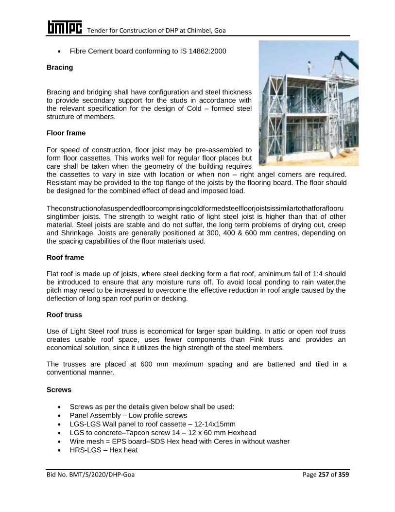
Tender for Construction of DHP at Chimbel, Goa
Bid No. BMT/S/2020/DHP-Goa Page 257 of 359
Fibre Cement board conforming to IS 14862:2000 Bracing Bracing and bridging shall have configuration and steel thickness to provide secondary support for the studs in accordance with the relevant specification for the design of Cold – formed steel structure of members. Floor frame
For speed of construction, floor joist may be pre-assembled to form floor cassettes. This works well for regular floor places but care shall be taken when the geometry of the building requires the cassettes to vary in size with location or when non – right angel corners are required. Resistant may be provided to the top flange of the joists by the flooring board. The floor should be designed for the combined effect of dead and imposed load.
Theconstructionofasuspendedfloorcomprisingcoldformedsteelfloorjoistsissimilartothatforafloorusingtimber joists. The strength to weight ratio of light steel joist is higher than that of other material. Steel joists are stable and do not suffer, the long term problems of drying out, creep and Shrinkage. Joists are generally positioned at 300, 400 & 600 mm centres, depending on the spacing capabilities of the floor materials used. Roof frame Flat roof is made up of joists, where steel decking form a flat roof, aminimum fall of 1:4 should be introduced to ensure that any moisture runs off. To avoid local ponding to rain water,the pitch may need to be increased to overcome the effective reduction in roof angle caused by the deflection of long span roof purlin or decking. Roof truss
Use of Light Steel roof truss is economical for larger span building. In attic or open roof truss creates usable roof space, uses fewer components than Fink truss and provides an economical solution, since it utilizes the high strength of the steel members. The trusses are placed at 600 mm maximum spacing and are battened and tiled in a conventional manner.
Screws
Screws as per the details given below shall be used:
Panel Assembly – Low profile screws
LGS-LGS Wall panel to roof cassette – 12-14x15mm
LGS to concrete–Tapcon screw 14 – 12 x 60 mm Hexhead
Wire mesh = EPS board–SDS Hex head with Ceres in without washer
HRS-LGS – Hex heat

Tender for Construction of DHP at Chimbel, Goa
Bid No. BMT/S/2020/DHP-Goa Page 258 of 359
CP board 6mm – WT8 CSK Phillips
Gypsum board – Flat heat self-driven type
Deck sheet/Wire mesh – SDS WT, CSK, Flat head
Extended Polystyrene Panel - Shall be of minimum density of 15 kg/m3. Wire Mesh – Shall be made of 4 mm dia wire of UTs 480 MPa with spacing 150 mm x 150 mm or 1.4 m dia of spacing 40 mm x 40 mm. Shotcrete – Short crete when used shall be of minimum grade M 25 Grade of concrete.
CONSTRUCTION Foundations for light steel framing are essentially the same as for any form of construction, although dead loads applied by the light steel frame will be much lower than in the concrete or masonry construction.
Construction phases of steel buildings resembles the phases of conventional reinforced concrete buildings. The sections manufactured as per design are numbered properly. Thepro- files are sent to site either as profile or panellized parts, con- side ring the distance of the construction site and transportation conditions. Profiles are assembled by trained assembly team at the construction site in line with the architectural plan. Only special studs are used during assembly, no welding is done. Once the assembly is done, the frame is filled with insulation materials (fibre glass, rockwool etc). Walls are then covered with standard boards or similar approved materials.
The sequence of construction comprises of foundation laying, fixing of tracks, fixing of wall panels with bracings as required, fixing of floor panels, fixing of roof panels, decking sheet, fixing of electrical & plumbing services and finally fixing of insulation material & walling panels. Electrical Gas and plumbing, services are installed through pre-punched service holes in the web of the steel forms. Plastic grommets and silicon seals are used to fasten and protect wiring and pipes from corrosion and damage arising from vibrations
Electrical cables running within floor insulation layer in the separating floor construction should be protected with cartridge fuses or mini circuit breaker. Wall panels are generally made by using heavy duty Cement Particle Board and Gypsum board.
It can also be made using high density extended polystyrene core plastered from outside using
Wire mesh and chicken mesh. Galvolume sheet of appropriate thickness can also be used as
cladding.

Tender for Construction of DHP at Chimbel, Goa
Bid No. BMT/S/2020/DHP-Goa Page 259 of 359
25. LIGHT GAUGE STEEL STRUCTURAL SYSTEM WITH PRECAST CONCRETE PANELS ON BOTH SIDE OF WALL AND LIGHT WEIGHT CONCRETE AS INFILL ABOUT THE TECHNOLOGY Light Gauge Steel Framed Structure with Infill Concrete Panels (LGSFS-ICP) Technology is an innovative emerging building and construction technology using factory made Light Gauge Steel Framed Structure (LGSFS), light weight concrete and precast panels. The LGS frame is a “C” cross-section with built in notch, dimpling, slots, service holes etc. produced by computerized roll forming machine. These frames are assembled using metal screws to form into LGSF wall and roof structures of a building. Provisions for doors, windows, ventilators and other cutouts as required are incorporated in the LGSFS.
Fig.1 Structural Details of LGSFS-Infill Concrete Wall
The LGS frames are manufactured in a factory and assembled in to LGSF wall structures and then transported to the construction site and erected wall by wall on a pre-built concrete floor as per the floor plan of the building. Steel reinforced concrete panels of size 610 mm x 305 mm x 20 mm thick are manufactured at factory and transported to site. These panels are fixed on either side of the LGSFS wall using self-drilling/tapping screws to act as outer and inner faces of the wall leaving a gap between them. This gap is then filled with light weight concrete using a special mixing and pumping machine. Electrical and plumbing pipes/conduits are provided in the service holes of the LGSFS before concreting is done. Self-compacting concrete is mixed and pumped into the gaps between two panels. The concrete flows and fills the gap and provides adequate cover to the LGS frames and joints. The con- crete shall also adhere to the concrete panels. After curing, LGSFS with in-fill concrete and panels (LGSFS-ICP) forms a monolithic sandwich composite wall structure with thermal and sound insulation properties. The roof structure of LGSFS-ICP building is constructed using metal/plastic formwork system with steel reinforced concrete as per structural design. Standard procedures are employed to concrete the roof slab. After curing for 96 h, the formwork is de-moulded and the wall and roof are putty finished. Door and window frames are fixed to the LGS frames and shutters fixed
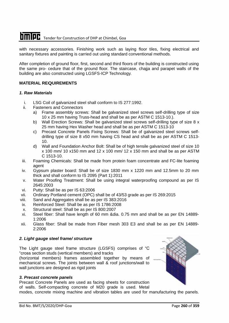
Tender for Construction of DHP at Chimbel, Goa
Bid No. BMT/S/2020/DHP-Goa Page 260 of 359
with necessary accessories. Finishing work such as laying floor tiles, fixing electrical and sanitary fixtures and painting is carried out using standard conventional methods. After completion of ground floor, first, second and third floors of the building is constructed using the same pro- cedure that of the ground floor. The staircase, chajja and parapet walls of the building are also constructed using LGSFS-ICP Technology. MATERIAL REQUIREMENTS 1. Raw Materials
i. LSG Coil of galvanized steel shall conform to IS 277:1992. ii. Fasteners and Connectors
a) Frame assembly screws: Shall be galvanized steel screws self-drilling type of size 10 x 25 mm having Truss-head and shall be as per ASTM C 1513-10.).
b) Wall Erection Screws: Shall be galvanized steel screws self-drilling type of size 8 x 25 mm having Hex Washer head and shall be as per ASTM C 1513-10
c) Precast Concrete Panels Fixing Screws: Shall be of galvanized steel screws self-drilling type of size 8 x50 mm having CS head and shall be as per ASTM C 1513-10.
d) Wall and Foundation Anchor Bolt: Shall be of high tensile galvanized steel of size 10 x 100 mm/ 10 x150 mm and 12 x 100 mm/ 12 x 150 mm and shall be as per ASTM C 1513-10.
iii. Foaming Chemicals: Shall be made from protein foam concentrate and FC-lite foaming agent
iv. Gypsum plaster board: Shall be of size 1830 mm x 1220 mm and 12.5mm to 20 mm thick and shall conform to IS 2095 (Part 1):2011
v. Water Proofing Treatment: Shall be using integral waterproofing compound as per IS 2645:2003
vi. Putty: Shall be as per IS 63:2006 vii. Ordinary Portland cement (OPC) shall be of 43/53 grade as per IS 269:2015 viii. Sand and Aggregates shall be as per IS 383:2016 ix. Reinforced Steel: Shall be as per IS 1786:2008 x. Structural steel: Shall be as per IS 800:2007 xi. Steel fiber: Shall have length of 60 mm &dia. 0.75 mm and shall be as per EN 14889-
1:2006 xii. Glass fiber: Shall be made from Fiber mesh 303 E3 and shall be as per EN 14889-
2:2006 2. Light gauge steel frame/ structure The Light gauge steel frame structure (LGSFS) comprises of “C “cross section studs (vertical members) and tracks (horizontal members) frames assembled together by means of mechanical screws. The joints between wall & roof junctions/wall to wall junctions are designed as rigid joints 3. Precast concrete panels Precast Concrete Panels are used as facing sheets for construction of walls. Self-compacting concrete of M20 grade is used. Metal modes, concrete mixing machine and vibration tables are used for manufacturing the panels.
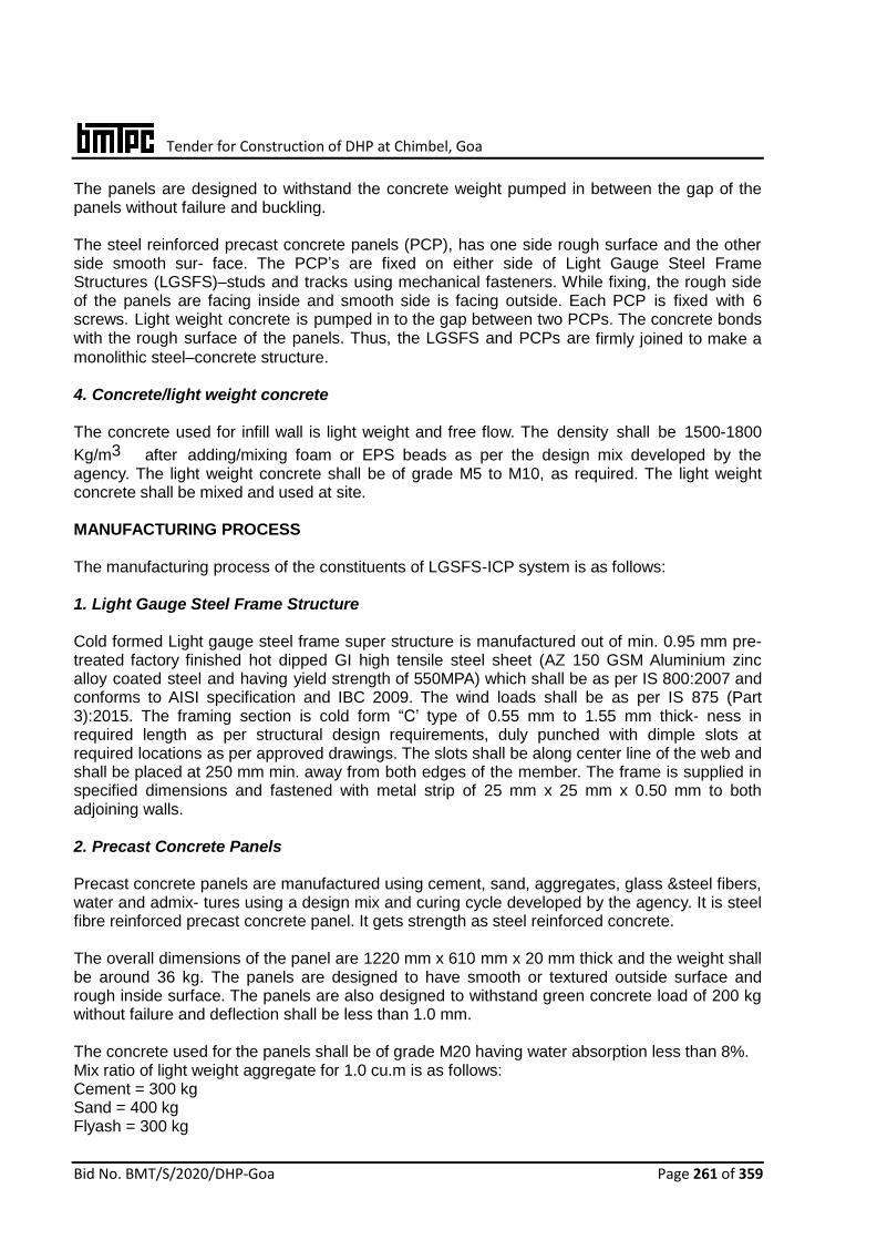
Tender for Construction of DHP at Chimbel, Goa
Bid No. BMT/S/2020/DHP-Goa Page 261 of 359
The panels are designed to withstand the concrete weight pumped in between the gap of the panels without failure and buckling. The steel reinforced precast concrete panels (PCP), has one side rough surface and the other side smooth sur- face. The PCP’s are fixed on either side of Light Gauge Steel Frame Structures (LGSFS)–studs and tracks using mechanical fasteners. While fixing, the rough side of the panels are facing inside and smooth side is facing outside. Each PCP is fixed with 6 screws. Light weight concrete is pumped in to the gap between two PCPs. The concrete bonds with the rough surface of the panels. Thus, the LGSFS and PCPs are firmly joined to make a monolithic steel–concrete structure.
4. Concrete/light weight concrete The concrete used for infill wall is light weight and free flow. The density shall be 1500-1800
Kg/m3 after adding/mixing foam or EPS beads as per the design mix developed by the agency. The light weight concrete shall be of grade M5 to M10, as required. The light weight concrete shall be mixed and used at site. MANUFACTURING PROCESS The manufacturing process of the constituents of LGSFS-ICP system is as follows: 1. Light Gauge Steel Frame Structure Cold formed Light gauge steel frame super structure is manufactured out of min. 0.95 mm pre-treated factory finished hot dipped GI high tensile steel sheet (AZ 150 GSM Aluminium zinc alloy coated steel and having yield strength of 550MPA) which shall be as per IS 800:2007 and conforms to AISI specification and IBC 2009. The wind loads shall be as per IS 875 (Part 3):2015. The framing section is cold form “C’ type of 0.55 mm to 1.55 mm thick- ness in required length as per structural design requirements, duly punched with dimple slots at required locations as per approved drawings. The slots shall be along center line of the web and shall be placed at 250 mm min. away from both edges of the member. The frame is supplied in specified dimensions and fastened with metal strip of 25 mm x 25 mm x 0.50 mm to both adjoining walls. 2. Precast Concrete Panels Precast concrete panels are manufactured using cement, sand, aggregates, glass &steel fibers, water and admix- tures using a design mix and curing cycle developed by the agency. It is steel fibre reinforced precast concrete panel. It gets strength as steel reinforced concrete. The overall dimensions of the panel are 1220 mm x 610 mm x 20 mm thick and the weight shall be around 36 kg. The panels are designed to have smooth or textured outside surface and rough inside surface. The panels are also designed to withstand green concrete load of 200 kg without failure and deflection shall be less than 1.0 mm. The concrete used for the panels shall be of grade M20 having water absorption less than 8%. Mix ratio of light weight aggregate for 1.0 cu.m is as follows: Cement = 300 kg Sand = 400 kg Flyash = 300 kg
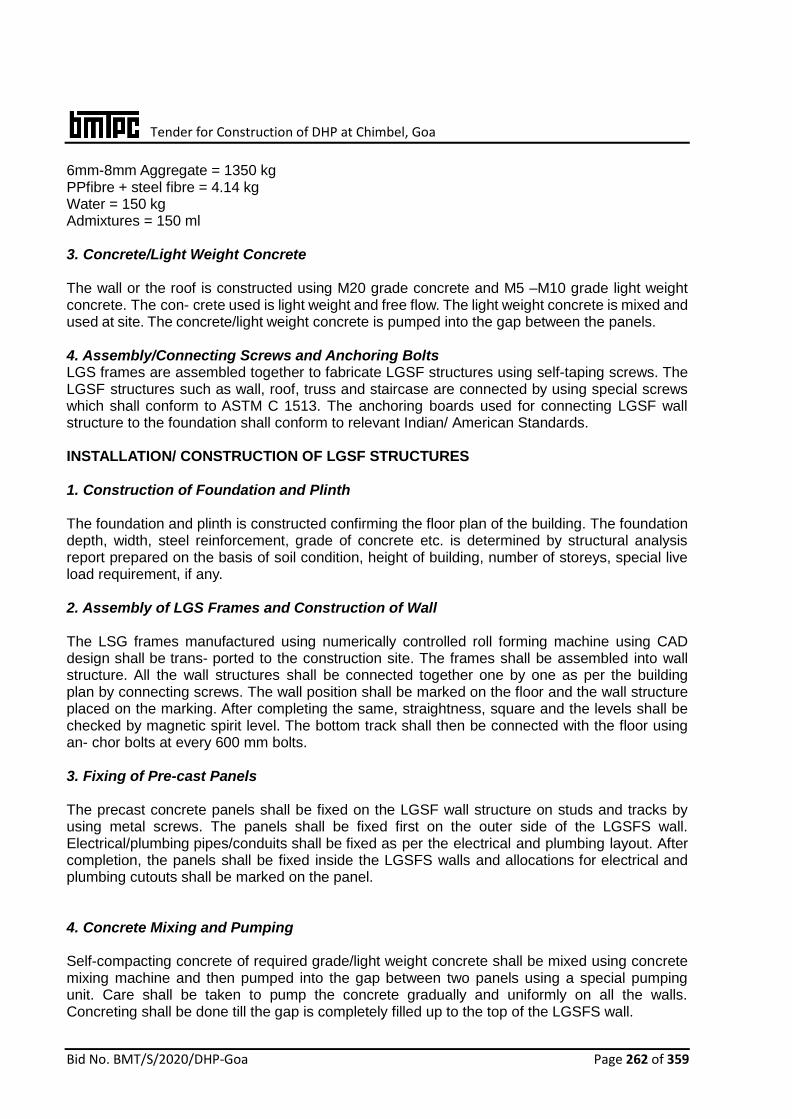
Tender for Construction of DHP at Chimbel, Goa
Bid No. BMT/S/2020/DHP-Goa Page 262 of 359
6mm-8mm Aggregate = 1350 kg PPfibre + steel fibre = 4.14 kg Water = 150 kg Admixtures = 150 ml 3. Concrete/Light Weight Concrete The wall or the roof is constructed using M20 grade concrete and M5 –M10 grade light weight concrete. The con- crete used is light weight and free flow. The light weight concrete is mixed and used at site. The concrete/light weight concrete is pumped into the gap between the panels. 4. Assembly/Connecting Screws and Anchoring Bolts LGS frames are assembled together to fabricate LGSF structures using self-taping screws. The LGSF structures such as wall, roof, truss and staircase are connected by using special screws which shall conform to ASTM C 1513. The anchoring boards used for connecting LGSF wall structure to the foundation shall conform to relevant Indian/ American Standards. INSTALLATION/ CONSTRUCTION OF LGSF STRUCTURES 1. Construction of Foundation and Plinth The foundation and plinth is constructed confirming the floor plan of the building. The foundation depth, width, steel reinforcement, grade of concrete etc. is determined by structural analysis report prepared on the basis of soil condition, height of building, number of storeys, special live load requirement, if any. 2. Assembly of LGS Frames and Construction of Wall The LSG frames manufactured using numerically controlled roll forming machine using CAD design shall be trans- ported to the construction site. The frames shall be assembled into wall structure. All the wall structures shall be connected together one by one as per the building plan by connecting screws. The wall position shall be marked on the floor and the wall structure placed on the marking. After completing the same, straightness, square and the levels shall be checked by magnetic spirit level. The bottom track shall then be connected with the floor using an- chor bolts at every 600 mm bolts. 3. Fixing of Pre-cast Panels The precast concrete panels shall be fixed on the LGSF wall structure on studs and tracks by using metal screws. The panels shall be fixed first on the outer side of the LGSFS wall. Electrical/plumbing pipes/conduits shall be fixed as per the electrical and plumbing layout. After completion, the panels shall be fixed inside the LGSFS walls and allocations for electrical and plumbing cutouts shall be marked on the panel. 4. Concrete Mixing and Pumping Self-compacting concrete of required grade/light weight concrete shall be mixed using concrete mixing machine and then pumped into the gap between two panels using a special pumping unit. Care shall be taken to pump the concrete gradually and uniformly on all the walls. Concreting shall be done till the gap is completely filled up to the top of the LGSFS wall.
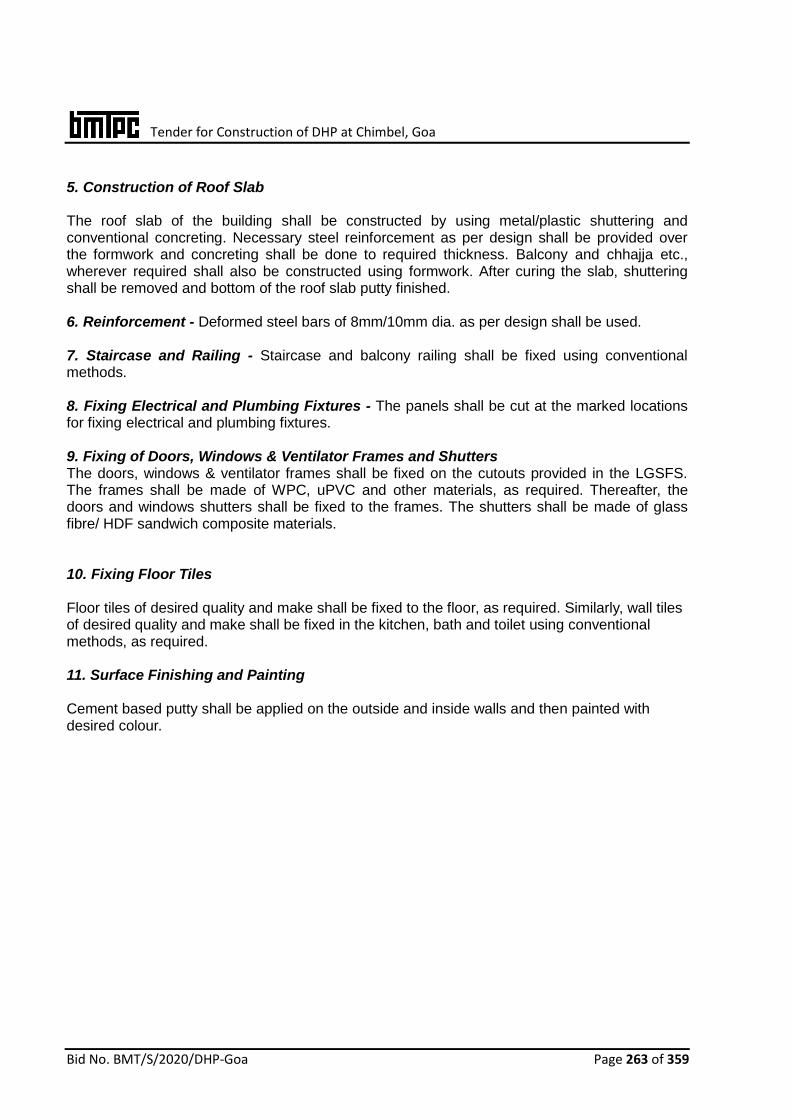
Tender for Construction of DHP at Chimbel, Goa
Bid No. BMT/S/2020/DHP-Goa Page 263 of 359
5. Construction of Roof Slab The roof slab of the building shall be constructed by using metal/plastic shuttering and conventional concreting. Necessary steel reinforcement as per design shall be provided over the formwork and concreting shall be done to required thickness. Balcony and chhajja etc., wherever required shall also be constructed using formwork. After curing the slab, shuttering shall be removed and bottom of the roof slab putty finished. 6. Reinforcement - Deformed steel bars of 8mm/10mm dia. as per design shall be used. 7. Staircase and Railing - Staircase and balcony railing shall be fixed using conventional methods. 8. Fixing Electrical and Plumbing Fixtures - The panels shall be cut at the marked locations for fixing electrical and plumbing fixtures. 9. Fixing of Doors, Windows & Ventilator Frames and Shutters The doors, windows & ventilator frames shall be fixed on the cutouts provided in the LGSFS. The frames shall be made of WPC, uPVC and other materials, as required. Thereafter, the doors and windows shutters shall be fixed to the frames. The shutters shall be made of glass fibre/ HDF sandwich composite materials. 10. Fixing Floor Tiles Floor tiles of desired quality and make shall be fixed to the floor, as required. Similarly, wall tiles of desired quality and make shall be fixed in the kitchen, bath and toilet using conventional methods, as required. 11. Surface Finishing and Painting Cement based putty shall be applied on the outside and inside walls and then painted with desired colour.

Tender for Construction of DHP at Chimbel, Goa
Bid No. BMT/S/2020/DHP-Goa Page 264 of 359
26. FACTORY MADE FAST TRACK MODULAR BUILDING SYSTEM ABOUT THE TECHNOLOGY Factory Made Fast Track Modular Building System comprises of prefabricated steel structure with different walling components. About 70 percent of the work is done in the factory with minimal usage of concrete, which enables system to deliver the building within a few days of work at site. The steel moduled are pre-fitted with flooring, ceiling tiles, electrical and plumbing fittings. The assembled steel modules are transported to the site for installation which is done using crane and other required machineries. Once all the components are assembled and erected at site, factory made 3–D Expanded Polystyrene (EPS) wall panels are fixed and shotcreting is done from both sides. The uniqueness of system is the efficient and simultaneous activities of site preparation and building construction in factory, rather than two phased customary process. DETAILS OF STRUCTURE Foundation Foundation shall be either strip or raft as per site conditions. The design and construction of foundation shall be carried out as per IS 1904:1986 and other related Indian Standards, as applicable. Steel Structure The structure consists of steel pillars, modules and other components designed for worst loading conditions as per IS 800:2007 and IS 801:1975. In addition, the structure shall be designed in accordance with IS 1893(Part 1) & IS 875 for seismic and wind load considerations, both individually and in combination, as applicable. Steel pillars shall be made by welding MS plate of 16mm thickness and steel tubes of size 200mm x 200mm having wall thickness varying from 3mm to 16mm depending upon the number of floors. The smaller pillar is fixed with sub-assemblies for modules. All the columns shall be checked for their safety and computations shall be done for the same for satisfying requirements of IS 800 and IS 801. Steel Staircase

Tender for Construction of DHP at Chimbel, Goa
Bid No. BMT/S/2020/DHP-Goa Page 265 of 359
Steel staircase shall be designed and fabricated using HR steel sheet of thickness 3mm / 4mm with MIG weld- ing process. Staircase is pretreated for surface cleaning using steel cleaning agent and painted with two coats of anti-corrosion primer and fire proof paint. Flooring The floor is made up of deck sheet and wire mesh of size 100mm x 100mm x 3mm thickness. The deck sheet is fixed on the modules ready after providing with utilities like plumbing and electrical etc. Flooring, roofing and ceramic tiles are fixed as per relevant specifications. Walling Walling is completed by using factory made EPS based wire mesh welded 3D panels. The panels are easy to install and manufactured using insulated polystyrene core covered on both sides by hot GI coated round wire
square mesh, duly connected by 33 connectors per m2. Door and Window The structure can accommodate any types of door and window frames and panels. Metal door frame pressed from 1.2/1.5mm thick galvanized steel sheet with mi- tered and welded construction may also be fixed. The doors used, however, should satisfy the performance requirements as per relevant Indian Standards. For doors not covered by any Indian Standards, third party certification may be adopted. Performance character- istics for dimensions & squareness, general flatness, impact indentation, flexure test, edge loading, shock absorption, buckling resistance, slamming and misuse as per relevant parts of IS 4020:1998 shall be required before accepting any doors for use. Utilities
i) Once the steel structure module is ready for electrical and plumbing work as per the
drawings, these utilities are planned & executed based on the services/utilities layout design and requirement of the floor area.
ii) After completion of services/utilities, the module is covered with deck sheet. Wire mesh and MS studs of required size are fixed on the deck sheet before laying of PCC flooring. After decking, PCC of M25 grade is laid for a total depth of 76mm and flooring tiles are fixed wherever required depending upon utilization of area. With all fittings the module is ready for shifting to the site.
Transport of Modules and Pillars along with accessories All the handling/transportation at site for erection are done by means of mechanical equipments such as tower & mobile cranes and trucks etc. Due care should be taken to avoid any damage to these modules, pillar and other elements. Special lifting points are provided in these modules so that handling stresses are kept to a minimum. Transportation are carried out in mainly two stages: i. From manufacturing plant to stacking yard. ii. From stacking yard to erection site. The transportation is carried out by using trucks of

Tender for Construction of DHP at Chimbel, Goa
Bid No. BMT/S/2020/DHP-Goa Page 266 of 359
desired capacity and length. Erection are carried out by cranes of suitable capacity at site. Walling Component Evaluation on the behavior of reinforced EPS Panel under flexural and Axial Compression load on 100 mm and 150 mm thick panels were satisfactory. Other performance characteristics are:
Thermal transmittance of Single Panel 0.537 w/m2k Acoustic Behavior 37 dB (noise reduction)
Water Penetration No penetration after 3h
Resistance to impact with softbody and hardbody Impacts of 90 & 1200 J –No crack

Tender for Construction of DHP at Chimbel, Goa
Bid No. BMT/S/2020/DHP-Goa Page 267 of 359
27. SPEED FLOOR SYSTEM
ABOUT THETECHNOLOGY
The Speed Floor System is a suspended
concrete flooring system using a roll formed
steel joist as an integral part of the final
concrete and steel composite floor. It is
essentially a hybrid concrete / steel tee-beam in
one direction and an integrated continuous one-
ways lab in other direction. The joists of
different depths are manufactured from pre-
galvanized high tensile steel in a one pass roll
former, where it is roll formed, punched,
pressed and slotted in a fully computerized
machine. The joist depth and the concrete
thickness are varied depending on the span,
imposed loads and other functional
considerations. The Speed floor composite floor
system is suitable for use in all types of
construction. The Speed floor joists are
designed and custom manufactured to suit
particular job conditions.
DESIGN
The design of the speed floor system is based on NZS3404(Part1&2),AS/NZS 4600 and the Australian Composite Standard AS 2327 (Part-I).The design load shall be taken as prevalent in IS875 (Part 1 & 3). Earthquake forces shall be taken in accordance with IS 1893 (Part-1).
The section properties and design parameters are calculated from the section geometry, supplementary full scale tests and finite elements analysis
THE JOISTS The joist is manufactured from G 350 Z 275 pre-galvanized steel conforming to AS 1397:2001. Size may be anyone of the following i.e. 200 mm , 250 mm, 300 mm, 350 mm and 400 mm, depending upon the design requirements. Concrete thickness may be 75mm

Tender for Construction of DHP at Chimbel, Goa
Bid No. BMT/S/2020/DHP-Goa Page 268 of 359
or 90mm as required.
The joist weight vis-à-vis the depth are given below:
Depth (mm)
Weight (kg/ ln m)
200 9.41
250 10.59
300 11.76
350 12.94
400 14.12
The top section of the joist is embedded in concrete and has following functions:
It is the compression element of the non composite joist dng construction
It is a‘ chair’ for the welded mesh or the reinforcement which develops negative mo• It locks in and supports the slab shuttering system (lock bar and plywood forms)
It becomes a continuous shear connector for the composite system. The bottom section of the joist acts as a tension member both during the construction phase and when the joist is acting compositely with the slab.ment capacity in the concretes lab over the joist
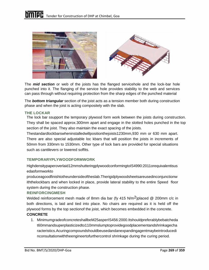
Tender for Construction of DHP at Chimbel, Goa
Bid No. BMT/S/2020/DHP-Goa Page 269 of 359
The mid section or web of the joists has the flanged servicehole and the lock-bar hole
punched into it. The flanging of the service hole provides stability to the web and services
can pass through without requiring protection from the sharp edges of the punched material
The bottom triangular section of the joist acts as a tension member both during construction
phase and when the joist is acting compositely with the slab.
THE LOCKAR The lock bar ssupport the temporary plywood form work between the joists during construction.
They shall be spaced approx.300mm apart and engage in the slotted holes punched in the top
section of the joist. They also maintain the exact spacing of the joists.
Thestandardlockbarswheninstalledwillpositionthejoists1230mm,930 mm or 630 mm apart.
There are also special adjustable loc kbars that will position the joists in increments of
50mm from 330mm to 1530mm. Other type of lock bars are provided for special situations
such as cantilevers or lowered soffits.
TEMPORARYPLYWOODFORMWORK
Highdensitypaperoverlaid12mmshutteringplywoodconformingtoIS4990:2011orequivalentisus
edasformworkto
produceagoodfinishtotheundersideoftheslab.Therigidplywoodsheetsareusedinconjunctionw
iththelockbars and when locked in place, provide lateral stability to the entire Speed floor
system during the construction phase.
REINFORCINGMESH
Welded reinforcement mesh made of 8mm dia bar (fy 415 N/m2)placed @ 200mm c/c in
both directions, is laid and tied into place. No chairs are required as it is held off the
plywood forms by the top sectionof the joist, which becomes embedded in the concrete.
CONCRETE
1. MinimumgradeofconcreteshallbeM25asperIS456:2000.Itshouldpreferablybebatcheda
t60mmandsuperplasticizedto110mmslumptoprovidegoodplacementandshrinkagecha
racteristics.Acuringcompoundshouldbeusedandanexpandingagentmaybeintroducedi
nconsultationwiththeengineertofurthercontrol shrinkage during the curing period.
Tender for Construction of DHP at Chimbel, Goa
Bid No. BMT/S/2020/DHP-Goa Page 270 of 359
2. The concrete should initially be placed evenly and continuously over the area to be
formed. Special attention should be given to ensure the concrete is screened and
finished to the specified thickness so that designed deflections are achieved in the
Speedfloor joists and the supporting structures.
3. Instructuresforcarparking,an expanding agent is generally used to reduce the effect
of shrinkage during initial cure and a curing compound is used to help control the
curing process.
ACCESSORIES
Edge angles
Astandardedgeformisavailableintwoheights75mm&90mm.Specialheightsandspeciallyshape
dedgeangles may be manufactured but would require longer lead times.
Jointers
Precutsectionsofgalvanizedsheetsteelmaybeprovidedtooverlayjointsintheplytoensuretheyareflushandremain well supported while the concrete is poured.
Lock bar HangerAngles
Agalvanizedsteelanglewithprepunchedlockbarholesisusedforsituationswherethelockbarsne
edsupporton slab edges parallel to the joists
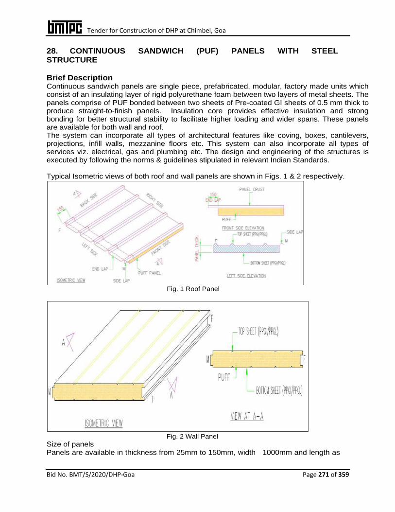
Tender for Construction of DHP at Chimbel, Goa
Bid No. BMT/S/2020/DHP-Goa Page 271 of 359
28. CONTINUOUS SANDWICH (PUF) PANELS WITH STEEL STRUCTURE
Brief Description Continuous sandwich panels are single piece, prefabricated, modular, factory made units which consist of an insulating layer of rigid polyurethane foam between two layers of metal sheets. The panels comprise of PUF bonded between two sheets of Pre-coated GI sheets of 0.5 mm thick to produce straight-to-finish panels. Insulation core provides effective insulation and strong bonding for better structural stability to facilitate higher loading and wider spans. These panels are available for both wall and roof. The system can incorporate all types of architectural features like coving, boxes, cantilevers, projections, infill walls, mezzanine floors etc. This system can also incorporate all types of services viz. electrical, gas and plumbing etc. The design and engineering of the structures is executed by following the norms & guidelines stipulated in relevant Indian Standards. Typical Isometric views of both roof and wall panels are shown in Figs. 1 & 2 respectively.
Fig. 1 Roof Panel
Fig. 2 Wall Panel
Size of panels Panels are available in thickness from 25mm to 150mm, width 1000mm and length as
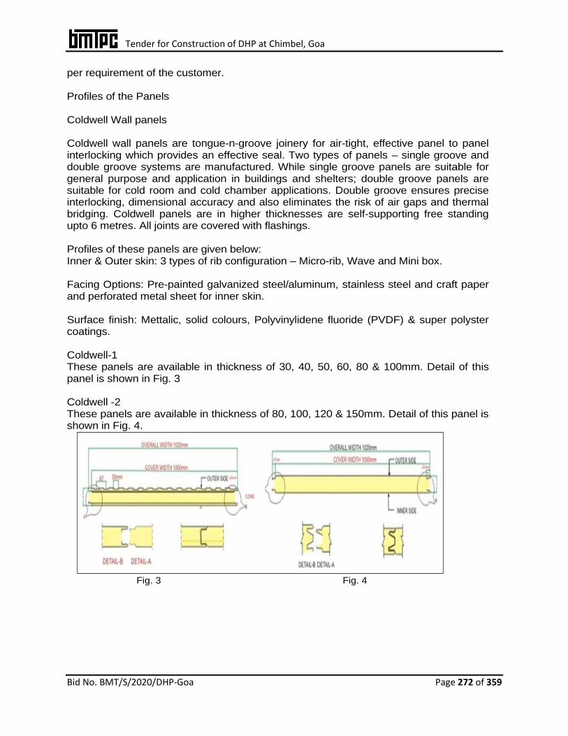
Tender for Construction of DHP at Chimbel, Goa
Bid No. BMT/S/2020/DHP-Goa Page 272 of 359
per requirement of the customer. Profiles of the Panels Coldwell Wall panels Coldwell wall panels are tongue-n-groove joinery for air-tight, effective panel to panel interlocking which provides an effective seal. Two types of panels – single groove and double groove systems are manufactured. While single groove panels are suitable for general purpose and application in buildings and shelters; double groove panels are suitable for cold room and cold chamber applications. Double groove ensures precise interlocking, dimensional accuracy and also eliminates the risk of air gaps and thermal bridging. Coldwell panels are in higher thicknesses are self-supporting free standing upto 6 metres. All joints are covered with flashings. Profiles of these panels are given below: Inner & Outer skin: 3 types of rib configuration – Micro-rib, Wave and Mini box. Facing Options: Pre-painted galvanized steel/aluminum, stainless steel and craft paper and perforated metal sheet for inner skin. Surface finish: Mettalic, solid colours, Polyvinylidene fluoride (PVDF) & super polyster coatings. Coldwell-1 These panels are available in thickness of 30, 40, 50, 60, 80 & 100mm. Detail of this panel is shown in Fig. 3 Coldwell -2 These panels are available in thickness of 80, 100, 120 & 150mm. Detail of this panel is shown in Fig. 4.
Fig. 3 Fig. 4
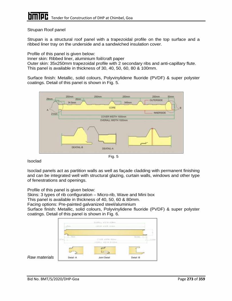
Tender for Construction of DHP at Chimbel, Goa
Bid No. BMT/S/2020/DHP-Goa Page 273 of 359
Strupan Roof panel Strupan is a structural roof panel with a trapezoidal profile on the top surface and a ribbed liner tray on the underside and a sandwiched insulation cover. Profile of this panel is given below: Inner skin: Ribbed liner, aluminium foil/craft paper Outer skin: 35x250mm trapezoidal profile with 2 secondary ribs and anti-capillary flute. This panel is available in thickness of 30, 40, 50, 60, 80 & 100mm. Surface finish: Metallic, solid colours, Polyvinylidene fluoride (PVDF) & super polyster coatings. Detail of this panel is shown in Fig. 5.
Fig. 5
Isoclad Isoclad panels act as partition walls as well as façade cladding with permanent finishing and can be integrated well with structural glazing, curtain walls, windows and other type of fenestrations and openings. Profile of this panel is given below: Skins: 3 types of rib configuration – Micro-rib, Wave and Mini box This panel is available in thickness of 40, 50, 60 & 80mm. Facing options: Pre-painted galvanized steel/aluminium Surface finish: Metallic, solid colours, Polyvinylidene fluoride (PVDF) & super polyster coatings. Detail of this panel is shown in Fig. 6. Raw materials
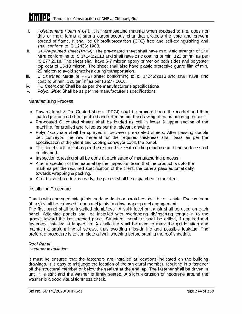
Tender for Construction of DHP at Chimbel, Goa
Bid No. BMT/S/2020/DHP-Goa Page 274 of 359
i. Polyurethane Foam (PUF): It is thermosetting material when exposed to fire, does not drip or melt; forms a strong carbonaceous char that protects the core and prevent spread of flame. It shall be Chlorofluorocarbon (CFC) free and self-extinguishing and shall conform to IS 12436: 1988.
ii. GI Pre-painted sheet (PPGI): The pre-coated sheet shall have min. yield strength of 240 MPa conforming to IS 14246:2013 and shall have zinc coating of min. 120 gm/m2 as per IS 277:2018. The sheet shall have 5-7 micron epoxy primer on both sides and polyester top coat of 15-18 micron. The sheet shall also have plastic protective guard film of min. 25 micron to avoid scratches during transportation.
iii. U Channel: Made of PPGI sheet conforming to IS 14246:2013 and shall have zinc coating of min. 120 gm/m2 as per IS 277:2018.
iv. PU Chemical: Shall be as per the manufacturer’s specifications v. Polyol Glue: Shall be as per the manufacturer’s specifications Manufacturing Process
Raw-material & Pre-Coated sheets (PPGI) shall be procured from the market and then loaded pre-coated sheet profiled and rolled as per the drawing of manufacturing process.
Pre-coated GI coated sheets shall be loaded as coil in lower & upper section of the machine, for profiled and rolled as per the relevant drawing.
Polyol/isocynate shall be sprayed in between pre-coated sheets. After passing double belt conveyor, the raw material for the required thickness shall pass as per the specification of the client and cooling conveyor cools the panel.
The panel shall be cut as per the required size with cutting machine and end surface shall be cleaned.
Inspection & testing shall be done at each stage of manufacturing process.
After inspection of the material by the inspection team that the product is upto the mark as per the required specification of the client, the panels pass automatically towards wrapping & packing.
After finished product is ready, the panels shall be dispatched to the client. Installation Procedure Panels with damaged side joints, surface dents or scratches shall be set aside. Excess foam (if any) shall be removed from panel joints to allow proper panel engagement. The first panel shall be installed plumb/level. A spirit level or transit shall be used on each panel. Adjoining panels shall be installed with overlapping rib/inserting tongue-in to the groove toward the last erected panel. Structural members shall be drilled, if required and fasteners installed at lapped rib. A chalk line shall be used to mark the girt location and maintain a straight line of screws, thus avoiding miss-drilling and possible leakage. The preferred procedure is to complete all wall sheeting before starting the roof sheeting. Roof Panel Fastener installation It must be ensured that the fasteners are installed at locations indicated on the building drawings. It is easy to misjudge the location of the structural member, resulting in a fastener off the structural member or below the sealant at the end lap. The fastener shall be driven in until it is tight and the washer is firmly seated. A slight extrusion of neoprene around the washer is a good visual tightness check.
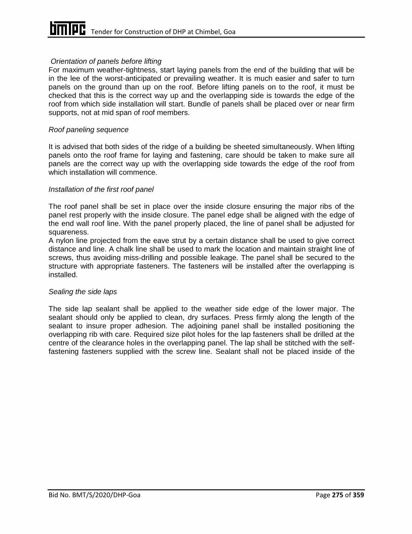
Tender for Construction of DHP at Chimbel, Goa
Bid No. BMT/S/2020/DHP-Goa Page 275 of 359
Orientation of panels before lifting For maximum weather-tightness, start laying panels from the end of the building that will be in the lee of the worst-anticipated or prevailing weather. It is much easier and safer to turn panels on the ground than up on the roof. Before lifting panels on to the roof, it must be checked that this is the correct way up and the overlapping side is towards the edge of the roof from which side installation will start. Bundle of panels shall be placed over or near firm supports, not at mid span of roof members. Roof paneling sequence It is advised that both sides of the ridge of a building be sheeted simultaneously. When lifting panels onto the roof frame for laying and fastening, care should be taken to make sure all panels are the correct way up with the overlapping side towards the edge of the roof from which installation will commence.
Installation of the first roof panel The roof panel shall be set in place over the inside closure ensuring the major ribs of the panel rest properly with the inside closure. The panel edge shall be aligned with the edge of the end wall roof line. With the panel properly placed, the line of panel shall be adjusted for squareness. A nylon line projected from the eave strut by a certain distance shall be used to give correct distance and line. A chalk line shall be used to mark the location and maintain straight line of screws, thus avoiding miss-drilling and possible leakage. The panel shall be secured to the structure with appropriate fasteners. The fasteners will be installed after the overlapping is installed. Sealing the side laps The side lap sealant shall be applied to the weather side edge of the lower major. The sealant should only be applied to clean, dry surfaces. Press firmly along the length of the sealant to insure proper adhesion. The adjoining panel shall be installed positioning the overlapping rib with care. Required size pilot holes for the lap fasteners shall be drilled at the centre of the clearance holes in the overlapping panel. The lap shall be stitched with the self-fastening fasteners supplied with the screw line. Sealant shall not be placed inside of the
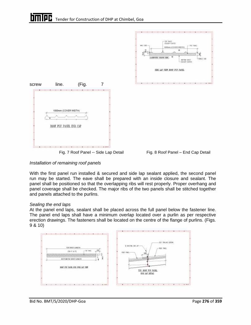
Tender for Construction of DHP at Chimbel, Goa
Bid No. BMT/S/2020/DHP-Goa Page 276 of 359
screw line. (Fig. 7
Fig. 7 Roof Panel -- Side Lap Detail Fig. 8 Roof Panel – End Cap Detail
Installation of remaining roof panels With the first panel run installed & secured and side lap sealant applied, the second panel run may be started. The eave shall be prepared with an inside closure and sealant. The panel shall be positioned so that the overlapping ribs will rest properly. Proper overhang and panel coverage shall be checked. The major ribs of the two panels shall be stitched together and panels attached to the purlins. Sealing the end laps At the panel end laps, sealant shall be placed across the full panel below the fastener line. The panel end laps shall have a minimum overlap located over a purlin as per respective erection drawings. The fasteners shall be located on the centre of the flange of purlins. (Figs. 9 & 10)

Tender for Construction of DHP at Chimbel, Goa
Bid No. BMT/S/2020/DHP-Goa Page 277 of 359
Fig. 9 End Over Lap Detail Fig. 10 End Lap Detail
Wall Panel Fastener installation It must be ensured that the fasteners are installed at locations indicated on the building drawings. It is easy to misjudge the location of the structural member, resulting in a fastener off the structural member or below the sealant at the end lap. The fastener shall be driven in until it is tight and the washer is firmly seated. A slight extrusion of neoprene around the washer is a good visual tightness check. The fasteners shall be installed by drilling holes on the ridge and not on the valley as shown in Fig. 5.
Checking flatness and overhang Before starting work it must be ensured that the supports for cladding are truly in the same plane the overhangs of panels from the top and bottom supports shall not exceed the limit, whilst also overhanging at least 50 mm into gutters. Necessary adjustments shall be made before laying panels, because it will be difficult or impossible to rectify later. Positioning first panel First panel shall be positioned before fixing to ensure that it is correctly located in relation to other parts of the building. It must be checked that the panel aligns with the end-wall (or its barge or fascia), the type of flashing or capping treatment to be used; andaligns correctly at its ends in relation to the gutter and ridge (or parapet or transverse wall). (Figs. 11 to 14)
Fig. 11Wall Panel Profile (Micro Rib) Fig. 12 Panel for Wall cladding
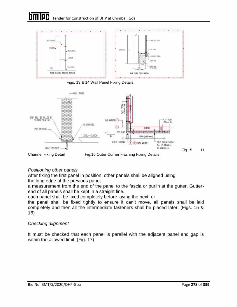
Tender for Construction of DHP at Chimbel, Goa
Bid No. BMT/S/2020/DHP-Goa Page 278 of 359
Figs. 13 & 14 Wall Panel Fixing Details
Fig.15 U Channel Fixing Detail Fig.16 Outer Corner Flashing Fixing Details Positioning other panels After fixing the first panel in position, other panels shall be aligned using: the long edge of the previous pane; a measurement from the end of the panel to the fascia or purlin at the gutter. Gutter-end of all panels shall be kept in a straight line. each panel shall be fixed completely before laying the next; or the panel shall be fixed tightly to ensure it can’t move, all panels shall be laid
completely and then all the intermediate fasteners shall be placed later. (Figs. 15 & 16) Checking alignment It must be checked that each panel is parallel with the adjacent panel and gap is within the allowed limit. (Fig. 17)

Tender for Construction of DHP at Chimbel, Goa
Bid No. BMT/S/2020/DHP-Goa Page 279 of 359
Fig. 17 Outer/Inner Corner Flashing Fixing Details at Partition Walls

Tender for Construction of DHP at Chimbel, Goa
Bid No. BMT/S/2020/DHP-Goa Page 280 of 359
Wall panel fixing with floor
Wall panel of 80 mm for outer wall shall be fixed with U-channel of size 40x82x40x1.2mm on floor. U-channel shall be fixed with M6x65mm dash fastener at 300mm c/c spacing. (Fig. 18) Wall panel fixing with slab Wall panel of 80 mm for outer wall shall be fixed with self-drilling screw of 12-14x120x4.8mm at 300mm c/c spacing using L-Angle of 50x50x2mm above slab. (Fig. 18) Wall partition panel fixing with slab top & bottom Wall partition panel of 80 mm shall be fixed over RCC slab by PVC gitti screw of 35mm and pop rivet at 200mm c/c spacing using L-Angle of 50x50x1.2mm on both side of panel above slab. (Fig. 18) Vertical corner closer Vertical corner shall be closed using pop rivet at 300mm c/c spacing by using L-Angle of 50x50x0.5mm. (Fig. 18)
Fig. 18 Fixing Details of wall with floor, slab & partition
Ceiling Panel Fastener installation It must be ensured that the fasteners are installed at locations indicated on the building drawings. It is easy to misjudge the location of the structural member, resulting in a fastener
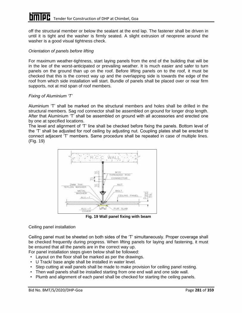
Tender for Construction of DHP at Chimbel, Goa
Bid No. BMT/S/2020/DHP-Goa Page 281 of 359
off the structural member or below the sealant at the end lap. The fastener shall be driven in until it is tight and the washer is firmly seated. A slight extrusion of neoprene around the washer is a good visual tightness check.
Orientation of panels before lifting For maximum weather-tightness, start laying panels from the end of the building that will be in the lee of the worst-anticipated or prevailing weather. It is much easier and safer to turn panels on the ground than up on the roof. Before lifting panels on to the roof, it must be checked that this is the correct way up and the overlapping side is towards the edge of the roof from which side installation will start. Bundle of panels shall be placed over or near firm supports, not at mid span of roof members.
Fixing of Aluminium ‘T’ Aluminium ‘T’ shall be marked on the structural members and holes shall be drilled in the structural members. Sag rod connector shall be assembled on ground for longer drop length. After that Aluminium ‘T’ shall be assembled on ground with all accessories and erected one by one at specified locations. The level and alignment of ‘T’ line shall be checked before fixing the panels. Bottom level of the ‘T’ shall be adjusted for roof ceiling by adjusting nut. Coupling plates shall be erected to connect adjacent ‘T’ members. Same procedure shall be repeated in case of multiple lines. (Fig. 19)
Fig. 19 Wall panel fixing with beam
Ceiling panel installation Ceiling panel must be sheeted on both sides of the ‘T’ simultaneously. Proper coverage shall be checked frequently during progress. When lifting panels for laying and fastening, it must be ensured that all the panels are in the correct way up. For panel installation steps given below shall be followed: • Layout on the floor shall be marked as per the drawings. • U Track/ base angle shall be installed in water level. • Step cutting at wall panels shall be made to make provision for ceiling panel resting. • Then wall panels shall be installed starting from one end wall and one side wall. • Plumb and alignment of each panel shall be checked for starting the ceiling panels.

Tender for Construction of DHP at Chimbel, Goa
Bid No. BMT/S/2020/DHP-Goa Page 282 of 359
• Inner and outer flashings shall then be installed to give temporary hold at wall panels. • Partition/other side wall panel shall also be installed with inner and outer flashings. • Ceiling panels shall then be lifted to the location after chcking the orientation as per the
drawings before lifting. • Strip flashing shall be installed on top of the ceiling panel after checking the alignment.
The chamber shall then be completed by following the above steps. Silicon sealant shall be filled at inner and outer face of all the panels. All flashings and accessories shall be installed as shown in the drawings. After that chemical filling shall be done as per the specifications. (Fig. 20)
Fig. 20 Ceiling with Wall Fixing Detail
Sealing the side laps Apply the side lap sealant to the weather side edge of the lower major. The sealant should only be applied to clean, dry surfaces. Press firmly along the length of the sealant to insure proper adhesion. Install the adjoining panel positioning the overlapping rib with care. Drill, at the centre of the clearance holes in the overlapping panel, required size pilot holes for the lap fasteners. Stitch the lap with the self-fastening fasteners supplied with the screw line. Sealant shall not be placed inside of the screw line.
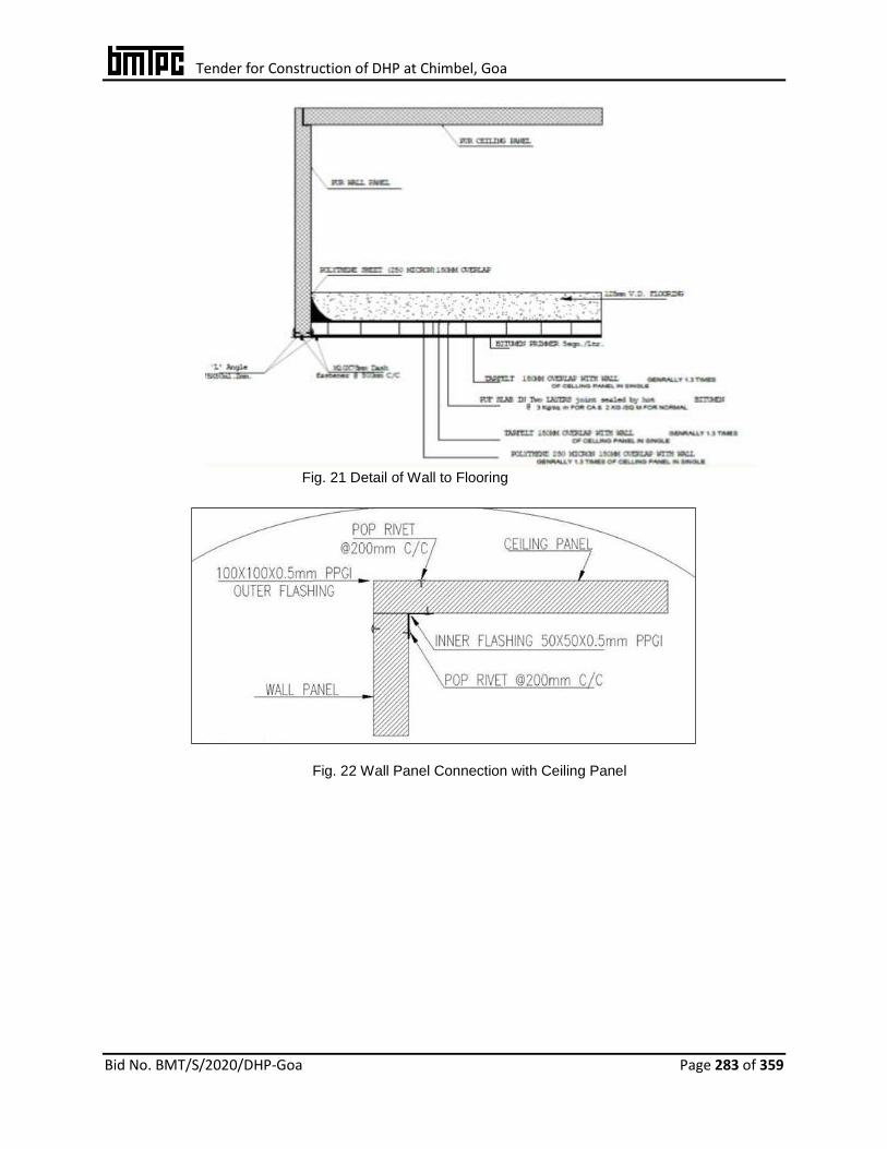
Tender for Construction of DHP at Chimbel, Goa
Bid No. BMT/S/2020/DHP-Goa Page 283 of 359
Fig. 21 Detail of Wall to Flooring
Fig. 22 Wall Panel Connection with Ceiling Panel
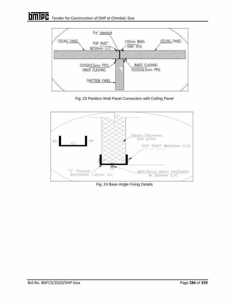
Tender for Construction of DHP at Chimbel, Goa
Bid No. BMT/S/2020/DHP-Goa Page 284 of 359
Fig. 23 Partition Wall Panel Connection with Ceiling Panel
Fig. 24 Base Angle Fixing Details
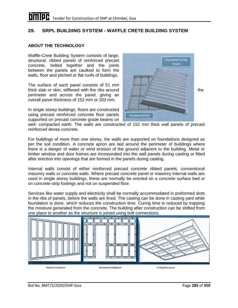
Tender for Construction of DHP at Chimbel, Goa
Bid No. BMT/S/2020/DHP-Goa Page 285 of 359
29. SRPL BUILDING SYSTEM - WAFFLE CRETE BUILDING SYSTEM ABOUT THE TECHNOLOGY Waffle-Crete Building System consists of large, structural, ribbed panels of reinforced precast concrete, bolted together and the joints between the panels are caulked to form the walls, floor and pitched or flat roofs of buildings. The surface of each panel consists of 51 mm thick slab or skin, stiffened with the ribs around the perimeter and across the panel, giving an overall panel thickness of 152 mm or 203 mm. In single storey buildings, floors are constructed using precast reinforced concrete floor panels supported on precast concrete grade beams on well- compacted earth. The walls are constructed of 152 mm thick wall panels of precast reinforced dense concrete. For buildings of more than one storey, the walls are supported on foundations designed as per the soil condition. A concrete apron are laid around the perimeter of buildings where there is a danger of water or wind erosion of the ground adjacent to the building. Metal or timber window and door frames are incorporated into the wall panels during casting or fitted after erection into openings that are formed in the panels during casting. Internal walls consist of either reinforced precast concrete ribbed panels, conventional masonry walls or concrete walls. Where precast concrete panel or masonry internal walls are used in single storey buildings, these are normally be erected on a concrete surface bed or on concrete strip footings and not on suspended floor. Services like water supply and electricity shall be normally accommodated in preformed slots in the ribs of panels, before the walls are lined. The casting can be done in casting yard while foundation is done, which reduces the construction time. Curing time is reduced by trapping the moisture generated from the concrete. The building after construction can be shifted from one place to another as the structure is joined using bolt connections.

Tender for Construction of DHP at Chimbel, Goa
Bid No. BMT/S/2020/DHP-Goa Page 286 of 359
The Waffle-Crete system consists of the following core elements:
Lightweight insulated precast insulated molds
Insulated curing covers that are used in conjunction with Waffle-Crete molds
Specialized equipment are designed for use with Waffle-Crete molds and covers
A construction methodology for casting and erecting concrete panels with molds and equipment.
Concrete panels cast in molds and then covered with a curing cover are removed from the mold and erected. Modular panels and bolted connections speed up the erection process. The system can be utilized for a variety of structural applications. TYPE OF PRECAST CONCRETE PANELS & WALLS 1. Standard reinforced precast concrete wall, floor and roof panels are 2.43 m wide and are manufactured in lengths of 3.65 m, 4.26 m, 4.87 m, 5.48 m, 6.09 m & 7.31 m. The surface of each panel shall consist of a 51mm thick slab, stiffened with tapered ribs around the perimeter and across the panel. The ribs shall be at approx. 1214 mm centres in one direction and 610 mm in the other and give an overall panel thickness of 152 mm or 203 mm, as required. 2. Harmonized reinforced precast concrete wall panels are 2.58 m high and are manufactured in lengths of 3.65 m, 4.26 m, 4.87 m, 5.48 m, 6.09 m & 7.31 m. All harmonized panels shall be 152 mm or 203 mm thickness. The surface of these panels shall consist of a 51 mm thick slab, stiffened with ribs around the perimeter and across the panel. The ribs shall be at approx. 610 mm centers, with two horizontal ribs along its length, one approx. 836 mm from the bottom and the other 418 mm from the top. These panels are used for window/door and window cut-outs. 3. Accessory Panels
a) Eave panels are used as decorative building trim and also cover waffle voids that may be exposed on the edges of cut roof panels.
b) Grade beams are used to cast a first floor foundation. Grade beam panel are keyed to fit floor panel ribs.
c) Stair panels are included an adjustable blockout to cast concrete stairs of variable width up to 2.44 m. Stair molds are available in 3.66 m & 6.10 m lengths with 164 mm risers.
4. Waffle-crete Floor Slabs
Thickness of concrete of topping may vary for different requirement of fire ratings. Floor slabs with a 60 minute fire-resistance rating shall require a minimum of 38 mm

Tender for Construction of DHP at Chimbel, Goa
Bid No. BMT/S/2020/DHP-Goa Page 287 of 359
concrete topping and floor slabs with a 120 minute fire-resistance rating shall require a minimum concrete topping of 75 mm or cladding to the underside. The joints between the plasterboard shall be sealed according to the manufacturer’s recommendations. Floor slabs with a 30 minute fire-resistance rating shall not require a concrete topping. Thickness of concrete topping may vary for different requirement of fire-ratings.
5. Type of Walls There are six types of internal and external walls which are used in conjunction with brick or concrete masonry walls etc. The wall panels are 152 mm or 203 mm thick overall.
i) Type 1 152 mm or 203 mm panels, unlined. ii) Type 2 Wall panels lined on one side with 12.5 mm thick gypsum plasterboard on 38
mm x 38 mm timber studs at 600 mm centers fixed to the panel ribs with screws into nailer blocks cast into concrete at 600 mm centers.
iii) Type 3 Wall panels lined on one side with 12.5 mm thick gypsum plasterboard of 63.5 mm x 35 mm x 0.71 mm thick on galvanized steel studs spaced at maximum 450 mm centres fixed to the ribs of the panels with 18 gauze steel galvanized wire wound around threaded 6 mm dia. galvanized steel fasteners hand-driven into a previously drilled hole in the rib of the floor panel.
iv) Type 4 Wall panels lined on one side with two layers of 12.5 mm thick gypsum plasterboard on galvanized steel studs with staggered joints similar to those used in Type 3 wall fixed to the panel ribs in the same manner as wall Type 3.
v) Type 5 Wall panels lined on one side with 12.5 mm thick gypsum plasterboard on top hat section galvanized steel channels fixed to the panel ribs as for wall Type 3 and insulated with 150 mm thick glass fibre.
vi) Type 6 Wall panels lined on one side with 12.5 mm thick gypsum plasterboard on timber studs fixed to the panel in the same manner as for wall Type 2 and insulated with 50 mm thick glass fibre.

Tender for Construction of DHP at Chimbel, Goa
Bid No. BMT/S/2020/DHP-Goa Page 288 of 359
ERECTION PROCEDURE
i) The properties of the soil on site shall be established by a professional engineer and the foundations and floors designed accordingly.
ii) The conventional cast-in-situ concrete foundations and surface beds with thickened edge beams or footings, shall be constructed on site in accordance with IS 1904:1986. The surface beds shall be laid on well compacted earth.
iii) When suspended floor panels and foundations are used, the grade beams shall be located under the longitudinal external walls of the building. They shall be placed in position on the surface of the ground on well compacted and levelled earth, laid end-to-end with butt joints.
iv) Where the span between the grade beams on either side of the building is such that it is necessary to use two or more floor panels across the width of the building, the ends of the panels at the joints where they meet shall be supported by additional grade beams, laid parallel to the external grade beams.
v) A continuous damp-proof membrane of a suitable plastic material, at least 0.25 mm thick, shall be provided under conventional concrete foundations and surface beds.
vi) The wall panels shall be hoisted and set in a vertical position, onto hardwood shims on the panel floor, concrete footing or surface bed, to create a space of uniform thickness under the bottom ribs of the wall panels, for the grouted joint.
vii) After levelling and aligning the wall panels on the shims, these shall be bolted to the floor panels and grade beams, or to the cast-in-situ concrete surface bed or foundations.
viii) Where threaded galvanized steel or stainless steel rods are used instead of anchor bolts, the ends of the rods shall be embedded in epoxy grout in holes drilled into the concrete, in strict accordance with the manufacturer’s instructions.
ix) Sand-cement grout having a compressive strength of 35MPa at 28 days shall be used in all horizontal joints between precast concrete components, unless otherwise specified by the engineer. A vibrator rod shall be used to ensure that the grout completely fills the joints.
x) Intermediate floors shall always consist of panels which are bolted together. There are three types of floor to wall connections. In the first case the floor panel shall be supported on top of an external wall, in the second case two floor panels shall be supported on an internal wall and in the third case a floor panel shall be supported on a ledger beam.
xi) Staircases which are of precast concrete shall be deigned in the normal manner and bolted to the supporting structure. At the beginning of a rise, the staircase shall be bolted with a 19 mm dia. vertical expansion anchor through a 76 mm x 76 mm 38 mm recess in the first step to the supporting structure. At the upper end of the rise, the staircase shall be fixed with a minimum of three 19 mm dia. x 254 mm long expansion anchors through the floor.
xii) On the outside of the building, the grout shall be partially raked out of the horizontal joint all round between the bottom of the external walls and the floor, concrete surface bed or footing to allow for the insertion of butyl rubber rope, followed by a bitumen impregnated foam plastics backer rod or bond breaker and caulked with one component polyurethane sealant.
xiii) The adjoining vertical ribs of the external panels shall be bolted together with 12.7 mm dia. galvanized steel or stainless steel bolts at 1.2 m centres through preformed or drilled holes for 152 mm thick panels or 20 mm dia. bolts at 1.2 m centres for 203 mm thick panels.

Tender for Construction of DHP at Chimbel, Goa
Bid No. BMT/S/2020/DHP-Goa Page 289 of 359
xiv) The vertical joints between external wall panels shall be caulked on the outside of the building with one component polyurethane sealant a bitumen impregnated foam plastics backer rod or bond breaker.
Roof Construction and Gable Wall
i) Triangular wall in-fill panels shall be hoisted into position on hardwood shims on top of the end walls of the building and bolted together through the adjoining outer horizontal ribs with 12.7 mm dia. galvanized steel or stainless steel bolts at 1.2 m centres.
ii) Precast concrete roof panels which span between the gable ends shall be hoisted into position on the sloping tops of the gable wall panels and bedded in 6 mm thick 4:1 sand: cement mortar, to form a pitched roof. The pitch shall generally be 30º.
iii) Galvanized steel plates, 60 mm long x 100 mm wide x 10 mm thick, at 2.4 m centres and cast into the ribs on the underside of the roof panels on either side of the ridge, shall be connected at the apex by welding a steel rod at the joint between each pair of plates.
iv) Depending on the structural design of the building and span of roof, the roof shall be supported at its apex by a ridge beam spanning between the gable wall infill panels at each end.
v) The adjoining roof panels shall be bolted together with 12.7 mm dia. galvanized steel or stainless steel bolts at 1.2 m centres, through preformed or drilled holes in the ribs of the panels. Before fully tightening the bolts, butyl rubber rope shall be inserted into the joint between the panels, followed by a bitumen impregnated foam plastics backer rod or bond breaker and the joint shall be caulked externally with one compound polyurethane sealant or equivalent.
vi) Flat roof shall consist of 152 mm or 203 mm thick precast reinforced ribbed wall panels bolted together and covered with a conventional waterproofing system on screed. Precast roof copings shall be bolted to the roof panels with 12 mm dia. bolts at 1219 mm centers.
vii) Internal walls on suspended floors shall usually be constructed of timber with 12.5 mm thick gypsum plasterboard cladding on both sides. Conventional burnt clay or concrete masonry internal walls shall usually be erected on conventional concrete surface beds and foundations.
viii) Internal walls shall also be plugged and screwed by means of steel brackets and bolts to the adjacent vertical ribs of the external walls at T-junctions and bolted or plugged and screwed to concrete surface beds or precast floors.

Tender for Construction of DHP at Chimbel, Goa
Bid No. BMT/S/2020/DHP-Goa Page 290 of 359
Windows, Doors, Services and Attachment of Fittings Timber or steel window and door frames shall be fitted into preformed openings in the wall panels and sealed all round with silicone sealant, unless they have been cast in during manufacture of the panels. Electrical and plumbing services shall be installed in the preformed notches on inside of the wall panels, or through sleeves cast into the ribs. Sanitary fittings, cupboards, shelving, and other heavy fittings shall be attached to the walls with galvanized steel bolts taken through holes drilled in the backing skin of the wall panels, or with expansion bolts fixed to the panel ribs. Protection against corrosion and finishes Steel bolts, anchor bolts, nuts, washers, threaded rods, brackets and cleats used at connections and joints in external walls, roofs, floors and foundations are hot-dip galvanized in accordance with IS 4759:1996 and coated with a metal primer, a good quality bituminous paint or epoxy painting or they are of stainless steel. The exterior surface of roofs and external walls shall be painted with two coats of suitable exterior grade acrylic emulsion paint. Painting of reminder of the building shall be carried out in accordance with the manufacturer’s requirements.
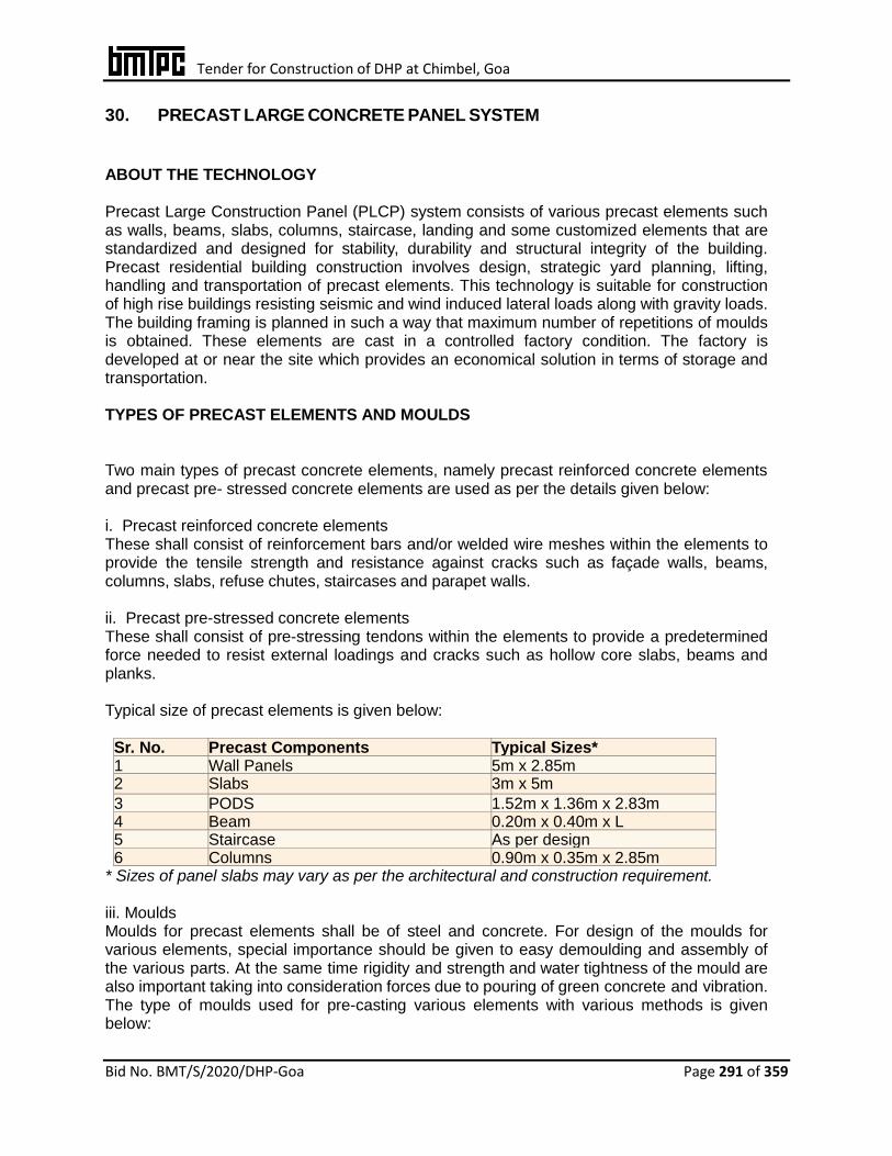
Tender for Construction of DHP at Chimbel, Goa
Bid No. BMT/S/2020/DHP-Goa Page 291 of 359
30. PRECAST LARGE CONCRETE PANEL SYSTEM
ABOUT THE TECHNOLOGY Precast Large Construction Panel (PLCP) system consists of various precast elements such as walls, beams, slabs, columns, staircase, landing and some customized elements that are standardized and designed for stability, durability and structural integrity of the building. Precast residential building construction involves design, strategic yard planning, lifting, handling and transportation of precast elements. This technology is suitable for construction of high rise buildings resisting seismic and wind induced lateral loads along with gravity loads. The building framing is planned in such a way that maximum number of repetitions of moulds is obtained. These elements are cast in a controlled factory condition. The factory is developed at or near the site which provides an economical solution in terms of storage and transportation. TYPES OF PRECAST ELEMENTS AND MOULDS Two main types of precast concrete elements, namely precast reinforced concrete elements and precast pre- stressed concrete elements are used as per the details given below: i. Precast reinforced concrete elements These shall consist of reinforcement bars and/or welded wire meshes within the elements to provide the tensile strength and resistance against cracks such as façade walls, beams, columns, slabs, refuse chutes, staircases and parapet walls. ii. Precast pre-stressed concrete elements These shall consist of pre-stressing tendons within the elements to provide a predetermined force needed to resist external loadings and cracks such as hollow core slabs, beams and planks. Typical size of precast elements is given below:
Sr. No. Precast Components Typical Sizes* 1 Wall Panels 5m x 2.85m 2 Slabs 3m x 5m
3 PODS 1.52m x 1.36m x 2.83m 4 Beam 0.20m x 0.40m x L 5 Staircase As per design 6 Columns 0.90m x 0.35m x 2.85m
* Sizes of panel slabs may vary as per the architectural and construction requirement. iii. Moulds Moulds for precast elements shall be of steel and concrete. For design of the moulds for various elements, special importance should be given to easy demoulding and assembly of the various parts. At the same time rigidity and strength and water tightness of the mould are also important taking into consideration forces due to pouring of green concrete and vibration. The type of moulds used for pre-casting various elements with various methods is given below:

Tender for Construction of DHP at Chimbel, Goa
Bid No. BMT/S/2020/DHP-Goa Page 292 of 359
Sr. No. Mould Type Uses
1 Conventional moulds Ribbed slab, beams, window panels, box type units and special elements
2 Battery moulds Interior wall panels, shell elements, roof and floor slabs
3 Tilting moulds Exterior wall panels where special finishes are required on one face or for sandwich panels
4 Long line prestressing beds Double tees, ribbed slabs, piles and beams
5 Extrusion machine Roof slabs and hollow core slabs
Battery Mould Tilting Mould POD Mould
Material Requirements Ordinary Portland Cement: Shall be of 43 grade as per IS 269:2015. Fine aggregate (M Sand): Shall be as per IS 383:2016 & IS 1542:1992 and 4.7 mm. Coarse Aggregates: Shall be as per IS 383:1970 and of 20 mm, 40 mm size Steel reinforcement: Shall be as per IS 1786:2008 Concrete: The grade of concrete shall be M 30 and slump for walls, floors and roofs shall be as per IS 456:2000. Brick masonry: Shall be designed as per IS 1905:1987 Solid Block work: Shall be as per IS 2185 (Part 1):1979 Aluminium: Shall be as per IS 733:1983 Glass: Shall be as per IS 2835:1987 Non-shrunk non-metallic grout: Cement based flowable grout shall have compressive strength
of 65 N/mm2, flexural strength of 9 N/mm2 at 28 days and E-modulus of 37000 N/mm2. Water proofing membrane: Fibre reinforced repair mortar shall have compressive strength of
45 N/mm2 at 28 days and density 2250 kg/m3 Baker Rod: Closed cell polymer based product shall have compressive strength of 0.45
kg/cm2 min. at 25% de-flection, density 22 kg/m3 min. and water absorption 0.14 gm/cm3
max. Corrugated sleeve: Hot dipped galvanized prime steel sheet shall be as per IS 277:2003. APPLICATIONS The system is used economically for mass housing projects and commercial buildings, etc. INSTALLATION 1. Precast Installation Proper planning and preparatory works shall be required before the actual installation of precast concrete elements in order to ensure quality installation. The following items shall be planned in advance:
Tender for Construction of DHP at Chimbel, Goa
Bid No. BMT/S/2020/DHP-Goa Page 293 of 359
i. Method of sequence of assembly and installation: Precast elements should be identified based on their location number and the tagged.
ii. Method of providing temporary support: Elements should be supported temporarily before these get stabilized. Generally structural members with adjustable ends shall be used for securing the panels. Shims should be used to adjust the panels to ensure dimensional correctness.
iii. Installation tolerances: Installation tolerances should be based on codal provisions and design considerations should be clearly indicated.
iv. Handling and rigging requirements: Elements should be checked for handling stresses before lifting and the cranes should have sufficient capacity to handle the precast panels. At least 10% impact should be considered while calculating the lifting capacity of the crane.
At site locations, panels shall be first unloaded and stacked or directly lifted by the crane. The element shall then be installed on the site and supported by temporary jacks. The cranes shall be released for next lifting once the temporary supports are in place. Shims shall be used to carefully align the element before grouting. The panels shall be grouted after the final adjustments are done. 2. Waterproofing External joints shall be sealed with baker rods and sealants after filling the joints with grout to avoid the leakage. Additional waterproofing treatment shall be provided at external joints and wet areas to ensure water tightness. 3. Mechanical, Electrical & Plumbing Fittings
Mechanical, electrical & plumbing fittings shall be kept open or concealed as per the requirements. For concealed fittings, provision for grooves, blockouts shall be made in casting moulds.
The conduits and electrical boxes shall be embedded and fixed in moulds before casting. For open fittings, these shall be fixed after erection at site.
For firefighting systems, provision of National Building Code (NBC) and local Building Byelaws shall be adhered to.
4. Fire Rating
• Precast concrete shall be designed for fire rating of 1 to 2 h based on codal requirements.
• Minimum precast concrete wall thickness of 120 mm shall be provided for 1 h fire rating as per IS 456:2000.
5. Finishes
Variety of shapes, colours, textures and finishes may be obtained with precast concrete.
The surface treatments shall be done by rebating, grooving, surface coatings, cement based renders, oxide coloring etc.
Precast concrete facades of various shapes, colours and textures may be moulded and installed.
IMPLEMENTATION OF PRECAST ELEMENTS 1. Casting Concrete

Tender for Construction of DHP at Chimbel, Goa
Bid No. BMT/S/2020/DHP-Goa Page 294 of 359
The procedure for casting concrete shall be as follows: i) Precast concrete elements shall be produced on horizontal/vertical, flat steel surfaced
tilting tables. ii) Prior to casting, electrical conduits and other required shall be fixed in position and
the mould treated with mould release agent. iii) Steel reinforcement shall be kept in position using adequate spacers to ensure correct
position and concrete cover. iv) After that side shutter shall be fixed. The high quality concrete shall be transported
from batching plant to the precast yard through transit mixer. v) Thereafter, concrete shall be carried to mould by gantry crane with concrete bucket. vi) During casting, table vibrators (as & when required) shall be used to achieve the best
compaction. Top surface shall be finished with hand operated trowel which gives smooth finish.
vii) Care should be taken on embedded items while concreting. viii) After casting, all exposed surfaces shall be covered with a tarpaulin (as and when
required) to avoid vaporization. Casted elements shall be de-moulded once the strength meets the design requirements and the units are then shifted to the stockyard. Thereafter, curing shall be carried out for 5 days.
Wall Panels Parapet Beams Spandrel
Solid Slab Panels POD Elements Staircase

Tender for Construction of DHP at Chimbel, Goa
Bid No. BMT/S/2020/DHP-Goa Page 295 of 359
2. Curing The curing of the prefabricated elements may be done by the normal methods of curing by sprinkling water and keeping the elements moist. This can also be done in the case of smaller elements by immersing them in specially made water tanks. 3. Screed Concrete for Flooring The surface for screed concrete shall be clean, free from dust, loose materials, lumps and foreign material. The screed shall generally be provided over the entire slab. In this case the entire slab shall act as a continuous structural diaphragm providing optimum load transfer mechanism for lateral loads. The screed shall be treated as a part of the compression zone for gravity loads on the slab. The design shall consider composite action between the slab & screed and compressive strength of screed in slab. Further, the interface shear between the slab & screed shall be checked for verifying adequate shear transfer capacity at the interface. i) Screed on haunches may be provided, only if the conduits are exposed, with the mutual
agreement between the project authority and the technology provider. In such cases, additional water proofing treatment of a reputed company shall be provided at the precast slab and site concrete stitch.
ii) Electrical conduits or any other embedment shall be laid as per approved drawings before screed concrete flooring.
iii) The reference level from main survey pillars shall be transferred and marked on side channels.
iv) While marking level, sloping direction in flooring shall be taken care as per approved drawing.
v) Before laying the concrete, cement slurry shall be spread on the slab surface for better bonding and filling of gaps between wall and slab soffit junction.
vi) The concrete should be placed from one end and shall be compacted immediately after placing and levelled uniformly.
vii) The vibrator should be applied smoothly and concrete compacted well. viii) The concrete shall be allowed to set so as to be in dry condition. ix) The trowelling shall start after concrete is set and reach dry condition. x) Curing shall be done by using bunds over the screed surface/wet hessian cloth.
4. De-moulding, Stacking and Transportation Casted elements are marked before lifting from the mould. All elements may be lifted without any dam- ages. Elements shall be stacked in horizontal position upto 5 feet. If vertical stacking the gap between the elements should be 150mm to 200 mm. The casted elements is transported to construction site. 5. Erection The process of erection and installation of panels during the construction cycle by using tower cranes shall be as follows: i. Before starting erection a survey of the area to receive precast elements shall be
done to monitor any difference in dimensions or levels exceeding the tolerances. In case of unacceptable tolerances, necessary action shall be taken for rectification.

Tender for Construction of DHP at Chimbel, Goa
Bid No. BMT/S/2020/DHP-Goa Page 296 of 359
ii) Installation shall be done by tower crane with sufficient capacity. Panels shall be shifted from the stack rack/ truck from yard to the nearest point of construction site and shall be kept above the truck during the construction or inside the storage racks as per the site situation.
iii) The necessary access for the truck to reach the nearest point of the tower shall be prepared before starting erection of the panels.
iv) Once the truck reaches the tower, chain and lifting clutch with required capacity and guide rope shall be attached to the precast panels to allow the workers to control the load to its final place.
v) As the elements are lifted to its final position above the cast-in-situ slab/precast panel, vertical and horizontal alignment of the panel shall be adjusted. The gap between the element and adjusted elements shall be maintained as per the drawings within the allowable tolerances. Shims and spacers shall be used for levelling and adjustment.
vi) Temporary propping jacks shall be provided for restraining the walls laterally until grouting.
vii) After completion of fixing, alignment of the panels shall be checked again. viii) Minor damages, if any to the precast panels shall be re- paired by approved materials. ix) After completion of installation and alignment, elements shall be handed over for
inspection. x) The joints between the precast wall panels shall be filled with joint filler material. xi) Precast slab shall be erected above the wall panels without any scaffolding system.
The electrical conduit/ fitting shall be done. After electrical works are completed, screed concrete shall be laid over the precast slab.
xii) Installation of the next floor shall start only after completion of screed concrete of the previous floor.
xiii) The sequence of erection shall be as follows:
Installation of precast wall panels above cast-in-situ slab
Provide temporary props/jacks for restraining of the walls laterally.
Grout the connection between the wall panels & ground floor slab and the joint between each wall panel.
Installation of precast slab panels above the erected precast wall panels.
Screed concrete above the slab after placing of electrical conduits / fittings
Installation of the wall panels over the floor slab.
Installation of the roof panels such as parapets etc.

Tender for Construction of DHP at Chimbel, Goa
Bid No. BMT/S/2020/DHP-Goa Page 297 of 359
31. INDUSTRIALIZED 3-S SYSTEM USING RCC PRECAST WITH OR WITHOUT
SHEAR WALLS, COLUMNS, BEAMS, CELLULAR LIGHT WEIGHT CONCRETE
SLABS/SEMI-PRECAST SOLID SLAB
ABOUT THE TECHNOLOGY The industrialized total prefab construction technology, being used since 1972, is based on factory mass manufactured structural prefab components conforming to provisions of relevant Indian Standards. The major precast elements are: • RCC hollow columns with notches • RCC solid beams (T/L/Square Shape) • Staircase • RCC precast slab • AAC precast slab • AAC precast block
In the system, precast dense concrete hollow column shell of appropriate sizes are used in combination with precast dense concrete rectangular / ‘T’ shape / ‘L’ Shape beams with light weight reinforced autoclaved cellular concrete/Precast RCC slabs for floors and roofs. The hollow columns are grouted with appropriate grade of in situ concrete. All the components and jointing of various structures are accomplished through on-site concerting along with secured embedded reinforcement of appropriate size, length and configuration to ensure monolithic continuous resilient, ductile and durable behaviour. Autoclaved Aerated Concrete (AAC) slabs can be used as floor / roof slabs. Joints are filled with reinforced screed concrete (minimum 40 mm thick) of M20 grade minimum. RCC screed is laid over entire area of slab before flooring / water proofing. Basic Material Requirements RCC Hollow Columns & Beam Concrete Shall conform to appropriate grade based on environmental and structural requirements condition as per IS 456 : 2000 Reinforcement Shall be of Fe 415 Grade or Fe 500 Grade as per IS 1786:2008 AAC Precast Slab of Grade 1 Density 551 – 650
Kg/m3 of IS 6073:2006
AAC Precast Block Density 451-550 Kg/m3 for
internal wall, 551-650 Kg/m3 for external wall as per IS 2185 (Pt. 3) :1984 Other Requirements: Evaluation of structural Requirement of Joints against vertical load, seismic and wind load shall be done as per IS Code.

Tender for Construction of DHP at Chimbel, Goa
Bid No. BMT/S/2020/DHP-Goa Page 298 of 359
DURABILITY
• Anti corrosive treatment given to reinforcement used in AAC slab panels for durability shall be as per IS Code. Concrete and cover requirement are as per durability clause of IS 456 :2000.
Fire Resistance Property of Block / Slab as Dwelling Unit AAC blocks / Slabs used will have fire rating as per the NBC norms for dwelling units. Thermal Behaviour
K value – 0.122 k cal/h/moc of AAC
blocks*. Acoustic Comfort Test For 100 mm ACC Wall, Sound absorption
is 38– 40 db* Ease of Fixing Services (Electricity & Plumbing) With pre-planning, electricity & plumbing services can easily be placed. Essential Requirements
Precasting yard / factory set up is required with facilities such as Casting Yard, Computerised batching plant, Moulds, Transportation facility, Stacking yard for materials & components, Lifting and loading facility, Laboratory to test raw material & finished products, Water tank of enough holding capacity as required for 2 – 3 days, Service road, etc.
Utmost attention is required for process engineering before taking up any field work. Close co-ordination between design crew, field staff and quality crew is essential.

Tender for Construction of DHP at Chimbel, Goa
Bid No. BMT/S/2020/DHP-Goa Page 299 of 359
3 2. WALLTEC HOLLOWCORE CONCRETE WALL
ABOUT THE TECHNOLOGY These are extruded non-load bearing concrete hollowcore wall panels manufactured in fully automated machines. Walltec wall panels are factory produced using light weight concrete made of river sand, crushed stone aggregate, light weight aggregate and Ordinary Portland cement. The concrete are extruded and cut while still wet to the requi- site length. Curing and sealing are followed for 24 to 48 hours by stacking and palletizing after which the walls are watered and cured for a further period of 7 to 8 days. After 15 days the panels are ready for transportation to site. Walls have cylindrical hollow cores incorporated with 7 No. 53 mm dia voids in the 92mm thickness and 6 No. 74 mm dia. voids for the 120 mm thickness panels. The corresponding
nominal weight shall be 140 kg/m2 and 170 kg/ m2 for 92 mm and 120 mm thick panels respectively. Hollows are incorporated in Walltec walls to reduce weight, facilitate mechanical, electrical and plumbing services through hollows, thereby increasing sound and thermal insula- tive properties. The sides of all panels are tongued and grooved to facilitate positive jointing. Walltec walls do not require stone or wood sills/frames to level surfaces for windows and openings. Lintels need not be cast as panels may be placed horizontally as lintels wherever required. Wash basins, cup-boards, mirrors, paintings etc. may be hanged with regular plug screws. Details of the wall panels showing hollow cores is given in Fig.1
Fig.1
Type and Size Walltec walls are produced in standard widths & thicknesses and in lengths to suit room height as per the details given below and shown in Figs. 2 & 3:
Wall width : 600 mm Wall thickness : 92 mm & 120 mm Wall Height : 2.40 m, 2.60 m, 2.85 m, 3.00 m, and 3.30 m
Weight : 92 mm : 140 kg/m2, 120 mm :170 kg/m2
Fig.2 Fig.3
Walltec walls use regular concrete of density 2350 kg/m3 and Walltec Lite uses light weight

Tender for Construction of DHP at Chimbel, Goa
Bid No. BMT/S/2020/DHP-Goa Page 300 of 359
concrete of density 1550 kg/m3. Tolerances The panels shall be produced in accordance with the following tolerances:
Length : ±10 mm Width : ±3 mm Thickness : ±3 mm Squareness of end : ±6 mm Differential bowing between adjacent panels of the : =15 mm same Length
Raw Materials i) OPC 53 grade cement shall conform to IS 12269:2013 ii) River sand and coarse aggregate 2-6 mm shall conform to IS 383:2016 iii) Flyash shall conform to IS 3812 (Part 1):2013 iv) Crushed Autoclaved Aerated Concrete (AAC) Waste Manufacturing Process The manufacturing process of Walltec wall panels is as follows: Raw Material Sieved River Sand, 6mm Stone Aggregate, AAC Waste shall be supplied to the plant by supplier where it shall be weighed and sieve analysis & silt content checked as per the quality assurance norms. Cement shall be supplied in closed bulkers directly from the manufacturers’ plant and fed into cement silo directly using blower. AAC Waste shall be crushed and sieved in using crusher & sieve combo machine which also has a dust collector shall collect superfine particles and the crushed AAC aggregate (8mm and lower fineness) shall be fed directly into the LWA (light weight aggregate) aggregate bin which shall be equipped with a moisture probe. Concrete Mixing Concrete required shall be batched and mixed at an automatic batching and mixing plant with Planetary Pan Mixer and Moisture probes. The relatively dry aggregates shall be automatically weighed & batched into the mixer from Aggregate Bins. Two of the Aggregate bins shall be equipped with moisture probes to ascertain accurate weighing and water content calculation later in the final concrete mix. Afterwards cement and water shall be added into the mixture. A low water-cement ratio of about 0.3 ensures that concrete is zero-slump and gains about 70% of its design strength within 12-24 hours of casting. Moisture content of the mixed concrete shall also be automatically controlled and adjusted by the software thus ensuring consistent concrete mix at all times. The software auto adjusts for water content based on readings of the moisture probes. After mixing, the concrete batch shall be fed to the conveying system, which brings fresh concrete to the hopper of the Acotec Wall – line where Walltec-Walls shall be cast, cut, trimmed, stacked, pre-cured, restacked and strapped into bundles. Extrusion The Walltec-Wall elements shall be formed in a continuously operating extruder. The

Tender for Construction of DHP at Chimbel, Goa
Bid No. BMT/S/2020/DHP-Goa Page 301 of 359
concrete shall be compacted onto thin base moulds, which support the products during the pre-curing time. Base moulds shall be automatically fed to the extruder as a continuous ribbon. The base mould length shall determine standard length of the products. There can simultaneously be maximum five plate lengths in the system. The extruder shall compact the concrete with extrusion screws against the packing bar and side walls. Top surface of the product shall be vibrated by a vibrating plate. Cutting After extruding, the products shall be cut according to the base mould length. A circular saw shall cut the fresh concrete on each base mould seam. Then the cut product together with the supporting plate shall be pulled to the stacker. Trimming When necessary, the fresh product shall be stopped at a specified point, where the manually adjusted circular saw cuts off the wanted trimming piece. Trimming length shall be max. 20 cm. The trimmed off concrete shall be recycled back to the extruder. Stacking Cut, fresh products shall be stacked into pre-curing stacks. Depending on the product thickness and weight each stack shall contain 4 to 10 products and base moulds. Stacks shall be supported by steel pallets, which are auto- matically fed underneath each stack. Pre-curing The stacks shall stay 12 to 24 hours in the pre-curing indoor storage area where natural pre-curing occurs for each stack which is covered with tarpaulin to stop any evaporation and moisture loss. The storage shall be an area where natural curing occurs. Product stacks shall be moved into and out from the stock area by a forklift. Restacking After pre-curing the products are strong enough to stand automatic handling. Products shall be separated from the base molds. Base molds shall be returned back to circulation trough a cleaning and oiling unit. The products shall be restacked to form delivery stacks with 4 - 10 products on top of each other. The stack shall be pushed against a wooden delivery pallet and turned on its side. Delivery stacks shall be strapped before transportation to delivery storage. Stacks must stay in the delivery storage where they shall be kept moist by external manual water sprinkling for at least 7 days before transporting to a construction site after 15 days on a Truck or Flat-bed Trailer. Loading of trucks shall be done with Forklift or Hydraulic Cranes. Installation Procedure i) Only two stacks shall be put on top of each other during stocking and transportation. ii) Panel stacks shall always be lifted from under wooden pallet with a lifting fork or belt. iii) The panel stacks shall be moved by forklift or trolley to construction site. Individual
panel may easily be moved by a simple wheel. Panels can also be moved manually by inserting a short tube (500mm) into the second hollow as handle. These shall always be transported sideways.
iv) Gluing agents (cement based adhesives) as per IS 9103:1999 shall be mixed as per the manufacturer’s instructions.
v) The line of wall shall be marked on the floor and ceiling before start of installation.

Tender for Construction of DHP at Chimbel, Goa
Bid No. BMT/S/2020/DHP-Goa Page 302 of 359
vi) Guiding boards shall be fixed on the floor and ceiling. The guiding support will automatically align the wall when lifting the panels straight into upright position.
vii) The gluing agent shall be spread on the side of the already installed panel. viii) Before the panel shall be lifted to upright position, it should be moved so that the panel
bottom is as close as possible to its correct position. After that the panel shall be lifted to upright position.
ix) This panel shall be pushed against the previous panel (and move up and down) so that tongue and groove are carefully positioned against each other and gluing agent is squeezed out. Correct thickness of joint between two panels shall be 1 to 2 mm.
x) The panel shall be positioned to correct level by using wooden wedges at the bottom and top of the panel erected earlier. The height of the panel should be about 10 to 50 mm shorter than free-room height.
xi) The top joint shall be filled with polyurethane foam. Correct thickness of joint shall be 5 to 10 mm.
xii) Alternatively, when same gluing agent as in sides is used for top joint, the panel shall be pushed against ceiling so that gluing agent is squeezed out. Correct thickness of joint shall be 1 to 2 mm. The surplus gluing agent shall be removed from joints after installation.
xiii) Bottom joint of the panel shall be filled with mortar or concrete. Correct thickness of joint shall be 10 to 40 mm.
xiv) ‘Shoulders’ shall be sawed or flat steel bar for door top portion fixed to the panels next to the door. The door top piece shall be glued by using polyurethane foam or gluing agents. The joints should be as thin as possible.
xv) All corners shall be strengthened with nail plugs (3 per corner). xvi) Paper or fibre tape shall be glued on to the corner joints and to the joints at a door top
portion before plastering. xvii) Flexible joints between panels shall be built after each 5 - 6m. Polyurethane foam or
mineral wool may be used as elastic joint material. xviii) The hollow boxes may be used for the cables and electrical boxes shall be fixed at
the desired points after drilling. xix) The panels need only a very thin skin coating (1-2 mm) before surface finishing. It
may be easier to do with a wide trowel. xx) All kinds of drilling and sawing can be easily made in the panels. xxi) The necessary tools required for installation shall be hammer, saw, screw driver,
level, meter rule, trowel, drill, trolley concrete cutter, steel bar, buckets and lifting bars.
Plumbing & Electrical Walltec panels shall have hollows of 53mm dia. in 92mm wall and 74mm dia. in 120mm wall to allow the passage of water pipes, electrical wiring, HVAC and hydraulic installations without making holes/chases. Plumbing and Electrical service fittings shall be pre-planned and shall be passed through hollow portions of the wall panels. Painting, Tiling and Cladding Painting shall be done directly or after applying a 2mm wall putty coat. Texture paint coat shall be directly applied to external surface for decorative effect. All tiling and cladding shall be directly fixed using regular cement mortar or tile adhesive.

Tender for Construction of DHP at Chimbel, Goa
Bid No. BMT/S/2020/DHP-Goa Page 303 of 359
33. ROBOMATIC HOLLOWCORE CONCRETE WALL PANELS Brief Description Robomatic wall panels are extruded non-load bearing concrete hollowcore wall panels manufactured in fully automated machines. These wall panels are factory produced using light weight concrete made of manufactured sand, crushed stone aggregate and Ordinary Portland cement. The concrete are extruded and cut while still wet to the requisite length. Curing and sealing are followed for 24 to 48 hours by stacking and palletizing after which the walls are watered and cured for a further period of 7 to 8 days. After 15 days the panels are ready for transportation to site. Wall panels have cylindrical hollow cores incorporated with 8 No. 44 mm dia voids in the 75mm thick, 6 No. 62 mm dia. voids for the 92 mm thick and 6 No. 74 mm dia. voids for the 120 mm thick panels. Hollowcores are incorporated in the walls to reduce dead weight, facilitate mechanical, electrical and plumbing services through hollows, thereby increasing sound and thermal insulate properties. The sides of all panels are tongued and grooved to facilitate positive jointing.These wall panels do not require stone or wood sills/frames to level surfaces for windows and openings. Lintels need not be cast as panels may be placed horizontally as lintels wherever required. Wash basins, cup-boards, mirrors, paintings etc. may be hanged with regular plug screws. Details of the wall panels showing hollow cores are shown in Figs.1, 2 & 3.
75mm thick panel Fig. 1
92mm thick panel Fig. 2
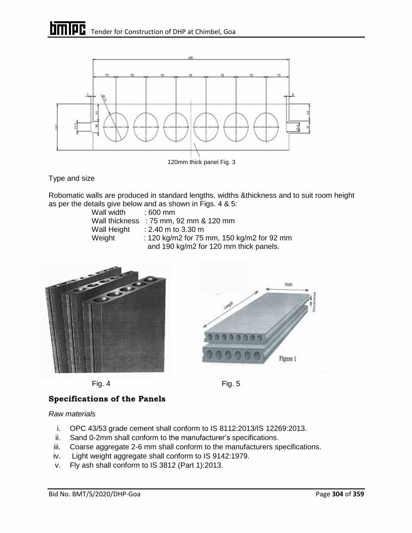
Tender for Construction of DHP at Chimbel, Goa
Bid No. BMT/S/2020/DHP-Goa Page 304 of 359
120mm thick panel Fig. 3
Type and size Robomatic walls are produced in standard lengths, widths &thickness and to suit room height as per the details give below and as shown in Figs. 4 & 5: Wall width : 600 mm Wall thickness : 75 mm, 92 mm & 120 mm Wall Height : 2.40 m to 3.30 m Weight : 120 kg/m2 for 75 mm, 150 kg/m2 for 92 mm and 190 kg/m2 for 120 mm thick panels.
Fig. 4 Fig. 5
Specifications of the Panels
Raw materials
i. OPC 43/53 grade cement shall conform to IS 8112:2013/IS 12269:2013.
ii. Sand 0-2mm shall conform to the manufacturer’s specifications.
iii. Coarse aggregate 2-6 mm shall conform to the manufacturers specifications.
iv. Light weight aggregate shall conform to IS 9142:1979.
v. Fly ash shall conform to IS 3812 (Part 1):2013.

Tender for Construction of DHP at Chimbel, Goa
Bid No. BMT/S/2020/DHP-Goa Page 305 of 359
vi. Water shall conform to IS 10500-2012.MS-C Channel 100x50mm x 6m shall be
manufactured frompre-galvanized high tensile steel conforming to IS 277:2018. vii. Adhesive, glue & bonding agents shall conform to the manufacturer’s specifications.
Production & Inspection
Production
Robomatic wall panels shall be machine made from sand, coarse aggregate and 53 grade
Portland cement. These shall be free from crack and nodules of free lime. These shall have
smooth rectangular faces with sharp corners and shall be uniform in colour.
Precast light weight hollow core wall panels shall be manufactured in Dry casting method.
The units shall be made with tongue and groove joint. Section of the tongue rebate shall be
21.9 mm (top) x 30mm (bottom) x 7mm (deep) for entire thickness of 75mm, 92mm and
120mm on one end of the panel and on other end of the panel, the size of groove rebate
shall be 22.8mm (top) x 32mm (bottom) x 8mm (deep). Panels shall have cylindrical hollow
core incorporated with 8 No. 44 mm dia voids in the 75mm thick, 6 No. 62 mm dia. voids for
the 92 mm thick and 6 No. 74 mm dia. voids for the 120 mm thick panels. Faces of panels
shall be flat, rectangular and smooth.
Adhesive
High strength and tensile adhesion non-shrink cementations grout premixed compound/void
filling expanding polyurethane foam (PU) shall be used for vertical and horizontal joints of
precast hollow core wall panels. Butt joints at corners shall be fixed with special frame
anchors.
Plumbing & Electrical
Robomatic wall panels shall have hollowcores of 44mm dia. in 75mm wall, 62mm dia in
92mm dia. and 74mm dia. in 120mm wall to allow the passage of water pipes, electrical
wiring, HVAC and hydraulic installations without making holes/chases. Plumbing and
Electrical service fittings shall be pre-planned and shall be passed through hollow portions of
the wall panels.
Painting, Tiling and Cladding
Painting shall be done directly or after applying a 2mm wall putty coat. Texture paint coat
shall be directly applied to external surface for decorative effect.
All tiling and cladding shall be directly fixed using regular cement mortar or tile adhesive.
Inspection -- Inspection shall be done at appropriate stages of manufacturing process Wall
panels shall be stored properly to ensure that no damage occurs during transportation.
Installation Procedure
The line of wall shall be marked on the floor and ceiling before start of installation. Guiding boards shall be fixed on the floor and ceiling. The guiding support will automatically align the wall when lifting the panels straight into upright position.The gluing agent shall be
Tender for Construction of DHP at Chimbel, Goa
Bid No. BMT/S/2020/DHP-Goa Page 306 of 359
spread on the side of the already installed panel.Before the panel shall be lifted to upright position, it should be moved so that the panel bottom is as close as possible to its correct position. After that the panel shall be lifted to upright position. This panel shall be pushed against the previous panel (and move up and down) so that tongue and groove are carefully positioned against each other and gluing agent is squeezed out. Correct thickness of joint between two panels shall be 1 to 2 mm.The panel shall be positioned to correct level by using wooden wedges at the bottom and top of the panel erected earlier. The height of the panel should be about 10 to 50 mm shorter than free-room height. The top joint shall be filled with polyurethane foam. Correct thickness of joint shall be 5 to 10 mm.Alternatively, when same gluing agent as in sides is usedfor top joint, the panel shall be pushed against ceiling so that gluing agent is squeezed out. Correct thickness of joint shall be 1 to 2 mm. The surplus gluing agent shall be removed from joints after installation. Bottom joint of the panel shall be filled with mortar or concrete. Correct thickness of joint shall be 10 to 40 mm.‘Shoulders’ shall be sawed or flat steel bar for door top portion fixed to the panels next to the door. The door top piece shall be glued by using polyurethane foam or gluing agents. The joints should be as thin as possible.All corners shall be strengthened with nail plugs (3 per corner).Paper or fibre tape shall be glued on to the corner joints and to the joints at a door top portion before plastering. Flexible joints between panels shall be built after each 5 – 6m. Polyurethane foam or mineral wool may be used as elastic joint material.The hollow boxes may be used for the cables and electrical boxes shall be fixed at the desired points after drilling. The panels need only a very thin skin coating (1-2 mm) before surface finishing. It may be easier to do with a wide trowel.All kinds of drilling and sawing can be easily made in the panels.
Tender for Construction of DHP at Chimbel, Goa
Bid No. BMT/S/2020/DHP-Goa Page 307 of 359
34. URBANAC PRECAST CONSTRUCTION TECHNOLOGY Brief Description Precast construction Technology is a system of casting concrete in a reusable mould or “form” which is then treated in a controlled environment, conveyed to the construction site and lifted to the place. Precast Construction Technology consists of various precast elements such as walls, beams, slabs, columns, staircase, landing and some customized elements that are standardized and designed for stability, durability and structural integrity of the building. Precast residential building construction involves design, strategic yard planning, lifting, handling and transportation of precast elements. This technology is suitable for construction of high rise buildings resisting seismic and wind induced lateral loads along with gravity loads. The building framing is planned in such a way that maximum number of repetitions of moulds is obtained. These elements are cast in a controlled factory condition. The factory is developed at or near the site which provides an economical solution in terms of storage and transportation. Types of precast elements Two main types of precast concrete elements, namely precast reinforced concrete elements and precast pre-stressed concrete elements are used as per the details given below: Precast concrete elements – Concrete components of a building prefabricated in precast yard or site and shall be installed in the building during construction. (See Fig. 1)
i. Precast reinforced concrete elements: These shall consist of reinforcement bars and/or welded wire meshes within the elements to provide the structural strength as per requirement of the component such as façade walls, beams, columns, slabs, staircases and parapet wall
ii. Precast pre-stressed concrete elements: These shall consist of pre-stressing tendons within the elements to provide a predetermined force needed to resist external loadings and cracks such as hollow core slabs, beams and planks.
Precast elements. Table 1.
Sr. No Precast Components Typical Sizes
1 Wall Panels Sizes of panels may vary as per requirement
2 Hollow Core Slabs
3 Beams
4 Staircase
5 Columns

Tender for Construction of DHP at Chimbel, Goa
Bid No. BMT/S/2020/DHP-Goa Page 308 of 359
Hollow core slab Pod Element
Fig. 1 Precast Concrete Elements
Moulds: Moulds for precast elements shall be of steel and concrete. For design of the moulds
for various elements, special importance should be given to easy de-moulding and assembly
of the various parts. At the same time rigidity and strength and water tightness of the mould
are also important taking into consideration forces due to pouring of green concrete and
vibration. The type of moulds used for pre-casting various elements with various methods is
given below (see Fig. 2):
Table 2
S. No. Mould type Uses
1. Conventional moulds Ribbed slabs, beams, window panels, box type units and
special elements
2. Tilting moulds Exterior wall panels where special finishes are required on
one face or for sandwich panels
3. Long line prestressing beds Double tees, ribbed slabs, piles and beams
Wall Panels Parapet Beams Staircase
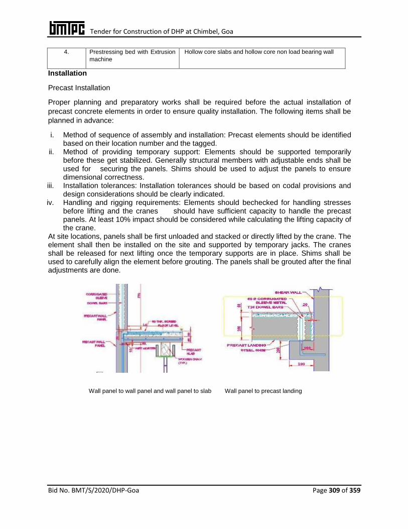
Tender for Construction of DHP at Chimbel, Goa
Bid No. BMT/S/2020/DHP-Goa Page 309 of 359
4. Prestressing bed with Extrusion
machine
Hollow core slabs and hollow core non load bearing wall
Installation
Precast Installation
Proper planning and preparatory works shall be required before the actual installation of
precast concrete elements in order to ensure quality installation. The following items shall be
planned in advance:
i. Method of sequence of assembly and installation: Precast elements should be identified based on their location number and the tagged.
ii. Method of providing temporary support: Elements should be supported temporarily before these get stabilized. Generally structural members with adjustable ends shall be used for securing the panels. Shims should be used to adjust the panels to ensure dimensional correctness.
iii. Installation tolerances: Installation tolerances should be based on codal provisions and design considerations should be clearly indicated.
iv. Handling and rigging requirements: Elements should bechecked for handling stresses before lifting and the cranes should have sufficient capacity to handle the precast panels. At least 10% impact should be considered while calculating the lifting capacity of the crane.
At site locations, panels shall be first unloaded and stacked or directly lifted by the crane. The element shall then be installed on the site and supported by temporary jacks. The cranes shall be released for next lifting once the temporary supports are in place. Shims shall be used to carefully align the element before grouting. The panels shall be grouted after the final adjustments are done.
Wall panel to wall panel and wall panel to slab Wall panel to precast landing
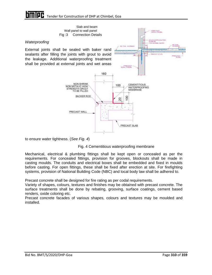
Tender for Construction of DHP at Chimbel, Goa
Bid No. BMT/S/2020/DHP-Goa Page 310 of 359
Slab and beam
Wall panel to wall panel Fig :3 Connection Details
Waterproofing
External joints shall be sealed with baker rand
sealants after filling the joints with grout to avoid
the leakage. Additional waterproofing treatment
shall be provided at external joints and wet areas
to ensure water tightness. (See Fig. 4)
Fig. 4 Cementitious waterproofing membrane
Mechanical, electrical & plumbing fittings shall be kept open or concealed as per the requirements. For concealed fittings, provision for grooves, blockouts shall be made in casting moulds. The conduits and electrical boxes shall be embedded and fixed in moulds before casting. For open fittings, these shall be fixed after erection at site. For firefighting systems, provision of National Building Code (NBC) and local body law shall be adhered to. Precast concrete shall be designed for fire rating as per codal requirements. Variety of shapes, colours, textures and finishes may be obtained with precast concrete. The surface treatments shall be done by rebating, grooving, surface coatings, cement based renders, oxide coloring etc. Precast concrete facades of various shapes, colours and textures may be moulded and installed.

Tender for Construction of DHP at Chimbel, Goa
Bid No. BMT/S/2020/DHP-Goa Page 311 of 359
35. K-WALL (PRE-CAST LIGHT WEIGHT HOLLOW CORE WALL PANEL)
1. Manufacture of Hollow Core Panel
Construction using “Hollow Core light weight concrete non-load bearing all panels manufactured in controlled factory conditions using battery moulds, light weight concrete (density 675 to 750 kg/m3) and other additives as per manufacturer’s specification. Panels are pre-cured naturally for 12-24 hrs and then water cured for seven days before installation. Panels are provided with tongue and groove joints for easy assembly. Panels are Battery mould panels. Panels are produced in standard widths & thickness and in lengths suitable to room height.
Standard width is 611 mm, height 2900 and thickness 65 mm, 80 & 100mm. Panels shall conform to tolerances w.r.t. Length : + 3mm, Width : + 2mm, Thickness : + 1mm, Squareness of end : +3mm.The structure will be complete in all respect with all plumbing, sanitary, electrical installations, painting and finishing as per approved drawings.
2. Structure Framing Section & Connection
Being non-load bearing, these panels are used with structural steel frame designed as per relevant Indian Standards and conforming to NBC 2016. The connection to framing section shall ensure required structural integrity & stability.
3. Floor/ Roof slab
RCC floor/ roof slab as per design conforming IS 456 over deck sheet shall be provided. The thickness and profile of decking sheet shall be verified with the erection drawings. Decking sheet has to be screwed to the joist with maximum spacing of 600 mm c/c for uniform action of concrete and joist. All the joints of decking sheets longitudinal direction require a minimum lap of 100 mm.
All relevant Indian Standards/ requirement of NBC shall be conformed.

Tender for Construction of DHP at Chimbel, Goa
Bid No. BMT/S/2020/DHP-Goa Page 312 of 359
36. INTEGRATED HYBRID SOLUTION - ONE Brief Description – IHS-ONE is an Intermediate Building System (IBS) having three main components:
walls, floor/roof and stairs. All 3 components are integrated to construct a building and hence named as “Integrated Hybrid Solution – ONE”. It has the integration of the following: Walls : Hydraform Prefabricated Mortar less Interlocking P-12 Technology. The
interlocking blocks are manufactured with a block making machine offsite or
onsite in an open shed. The blocks can be of cement-flyash-block or cement-
soil block.
Floors/Roof : Mechanized Precast R.C. Plank & Joist system : The RC planks
as well as joists are partially precast either offsite or on site. After placement
as floor/roof elements, the haunches are filled with in-situ concrete. A layer of
ferrocement course is laid with wire mesh reinforcement. The assembly
provides monolithic behavior and diaphragm action to transfer horizontal loads
to supporting members.
Ferrocement Elements: Mechanized precast/prefab Ferrocement staircase,
kitchen shelves, kitchen platforms, sunshades, lintel bands, water tanks, fines.
The Integrated Hybrid Solution – ONE uses the technologies, which can be bridged
to erect a structure by using precast floor/roof system bridged with interlocking
mortarless block wall system in a load bearing system upto G+3 structures. Both
roof/floor and walling system can also be bridged with RC framed structure as well
as steel structure in multistoried structure providing a complete solution for a
building structure.
The system has been designed for all loads including earthquake. TYPES OF PRECAST ELEMENTS 1 FOR WALLING
2 THE INTERLOCKING BLOCK
3 There are two major objectives of any dry-stack interlocking block
system. The first objective is to be self-aligning. Features requiring for
self-aligning interlocking blocks include:-
• Fitting into each other without adjustment (e.g. cutting,
shaving or shining)
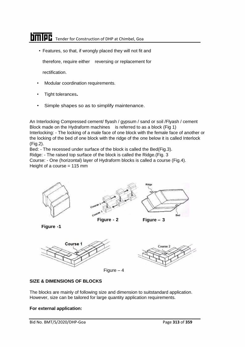
Tender for Construction of DHP at Chimbel, Goa
Bid No. BMT/S/2020/DHP-Goa Page 313 of 359
• Features, so that, if wrongly placed they will not fit and
therefore, require either reversing or replacement for
rectification.
• Modular coordination requirements.
• Tight tolerances.
• Simple shapes so as to simplify maintenance.
An Interlocking Compressed cement/ flyash / gypsum / sand or soil /Flyash / cement
Block made on the Hydraform machines is referred to as a block (Fig 1)
Interlocking: - The locking of a male face of one block with the female face of another or
the locking of the bed of one block with the ridge of the one below it is called Interlock
(Fig.2).
Bed: - The recessed under surface of the block is called the Bed(Fig.3).
Ridge: - The raised top surface of the block is called the Ridge.(Fig. 3
Course: - One (horizontal) layer of Hydraform blocks is called a course (Fig.4).
Height of a course = 115 mm
Figure -1
Figure - 2 Figure – 3
Figure – 4
SIZE & DIMENSIONS OF BLOCKS
The blocks are mainly of following size and dimension to suitstandard application. However, size can be tailored for large quantity application requirements.
For external application:

Tender for Construction of DHP at Chimbel, Goa
Bid No. BMT/S/2020/DHP-Goa Page 314 of 359
for load bearing the block sizes are :
HF190 : 240mm (l) x190mm(w) x 115mm (h)
HF 220 : 240 mm (l) x 220 mm (w) x 115 mm (h)
HF 150 : 240mm (l) x 150 mm (w) x 115mm (h)
For partition walls:
HF 100:240mm(l)x100mm(w)x115mm(h) or 220mm(h)
Special blocks:
For conduits and embedding of reinforcement bars
Types of precast elements (For floor / roof)
Floor / Roof is a precast system named as Precast RC Planks & Joists System. The precast planks are partially precasted and when placed over wall / joists/beams, serve as form work for cast-in-place concrete. The haunches are filled in situ along with the negative reinforcement of 6 mm dia in haunches.This system consists of precast R.C. planks 60 mm thick supported over partially precast RC joists of 150 mm width and 150 to 200 mm depth with stirrup projecting out on the top. To provide for Tee-beam effect with the joist, the plank is made partly 30 mm thick. A 100 mm wide tapered concrete fillet
Precast Planks :
The RC Planks typically have 3 Nos. 6mm dia bars as main reinforcement and 3mm dia mild steel wire @ 150mm c/c or 6 mm dia bars up to 200mm c/c as transverse reinforcement. The in-situ concrete at every joint with 2 no. 6mm dia as negative reinforcement form the flange of the tee beam along with the joists and provide monolithic effect.is provided for strengthening the haunch portion during handling and erection
Partially Precast RCC Joist
It is a rectangular shaped joist 150 mm wide and the precast portion is generally 150 mm deep. The portion above is casted while laying in-situ concrete over planks. The stirrups remain projected out of the precast joist. Thus the total depth of joist becomes 210 mm. The joist is designed as composite Tee-beam with 60 mm thick flange comprising of 30 mm precast and 30 mm in-situ concrete. This section of the joist can be adopted upto span of 4 m. For smaller spans, the depth of precast joist can be reduced. For longer spans the depth of joist can be increased. However, the self-weight of joist shall increase and lifting would require simple chain-pully block.
Precast Ferrocement / Ferrocrete elements

Tender for Construction of DHP at Chimbel, Goa
Bid No. BMT/S/2020/DHP-Goa Page 315 of 359
Ferrocement is a special form of reinforced concrete. It is a composite material consisting of cement sand mortar (matrix) reinforced with layers of small diameter wire meshes. It differs from conventional reinforced concrete primarily by the manner in which the reinforcement is arranged within the brittle matrix. Since its behavior is quite different from that of conventional reinforced concrete in performance, strength and potential applications, it is classed as a separate material. Usually steel bars are also used in addition to wire mesh, to form a steel skeleton, which helps in retaining the required shape of the ferrocement components once the cement mortar hardens. The wire mesh reinforcement is uniformly distributed across the thickness of the element.
Ferrocement Shelves
Conventionally, cooking platforms are provided in 50 mm thick cast-in-situ RCC slabs. Precast ferrocement cooking shelves are used which are easier to cast, easier to handle and light weight besides being economical. The cooking platform has 25m thickness having one layer of welded mesh 25x75mm of 2 mm dia and two layers of chicken mesh 24 gauge, embedded in cement mortar.
Ferrocement Staircase Steps
Stair case is an essential part of any building as it provides access to different floors in the structure. Conventionally, staircases are constructed in Reinforced Cement Concrete, having a waist slab, treads and risers, hand rails etc.Precast ferrocement steps (tread & riser unit) are 25 mm thick, supported on walls / beams and provide aesthetic look like a folded slab.
Ferrocement Water Tanks
There are a number of options available to store water viz. brick masonry tanks, RCC water tanks, PVC tanks etc.Ferrocement tanks of 1200 litres & 1600 litres have been provided which have a dia of about 1.5m. For these tanks, the base and the cylindrical container are casted separately. The wall thickness is 25mm. Two layers of chicken mesh along with GI wire in helical shape are provided in the walls.
Use of System
Interlocking Blocks as :
• load bearing walls non-load bearing
• partition infill wall in multi-storey building
RC Plank & Joists System as :
• Floor / roof slabs in all class of buildings In load bearing structures
• In RCC Framed structures

Tender for Construction of DHP at Chimbel, Goa
Bid No. BMT/S/2020/DHP-Goa Page 316 of 359
• In steel structures • In RCC – Steel composite structures
Ferrocement elements :
• Sunshades Shelves Fins • Water tanks Flooring tiles Terracing tiles Drains • Drain covers
Specifications of raw materials
Interlocking blocks
The main raw materials for production of interlocking blocks are Cement +
Flyash + Sand for Flyash Blocks or cement + soil for soil blocks, which are
available cheaply and in abundance. The ingredients are compressed and
compacted in the block making machine.The Mix design and proportions of
the ingredients depends upon the nature of fly ash and the strength of block
required.Fly ash grade II AS PER is 3812-1981 is used for Blocks.Sample
mix design for achieving respective class strength
Cement Gypsum Lime Sand Fly-Ash
Class 75 6% 3% 3% 25% 63%
Class 100 7% 3% 4% 30% 56%
Class 125 8% 3% 4% 35% 50%
RC Planks & Joists: The materials used are cement, aggregates, water, reinforcement, admixtures.
Ferrocement elements:
The materials used for ferrocement are cement, sand, wire mesh and steel bars.
Quality of Materials :
All the raw materials used shall be as per relevant IS Codes.

Tender for Construction of DHP at Chimbel, Goa
Bid No. BMT/S/2020/DHP-Goa Page 317 of 359
Manufacturing / production process
Interlocking block
Blocks are produced in a special Block Making Machine of
different production capacity.
Ingredients (sand, flyash and gypsum) or soil, flyash are
mixed dry in pan mixer for one minute. Then cement is
added. When homogenous mixing is achieved, water is
mixed.
The moisture in the mix is checked with drop test.
The sequence of operation of machine is :
• Lower the main ram
• Open the pre-compression ram
• Fill the compression chamber with raw material mixture
in the hopper.
• Close the pre-compression ram.
• Raise the main ram to compress the block
• Open the pre-compression ram
• Raise the main ram fully to eject the blocks.
• Remove and stack the blocks
• Curing done for 14 days.
RC Planks & Joists
The reinforcement cage comprising of 3 Nos., 6mm dia main reinforcement and
distribution bars 6mm @ 200mm spacing is prepared. 3 Nos. of cover blocks are also
binded. The cage is placed on the pallet over the Vibrating table. Two planks are casted
together on one table. The twin moulds are tightened with the table. Min. M-25 strength
of concrete is poured in a measured quantity. Vibration is done with a timer. No smooth
finish is required on top of planks. Rather it is roughened with a steel broom.After the
casting, the mould is lifted and the plank along with pallet is lifted and placed for curing.
After 48 hours the plank is demoulded from the pallet and shifted to curing yard. The
process takes about 3 minutes, when self compacting concrete is used no vibration is
required.The precast joists are casted on a leveled platform using MS Channel as form
work. The reinforcement cage with triangular stirrups having one bar on top and 2 or 3
bars in bottom is placed. Concrete is poured and compacted with a 25mm needle
vibrator. The lower part of joists is casted up to top of the MS Channels. The edges are
finished. The mould are removed after 4 hours of initial setting and reused. The joists
are cured with gunny bags or under polythene cover. After 14 days they are shifted to
stacking yard.
Ferrocement elements
The reinforcement cage is prepared for ferrocement items such as sunshades, platform,
shelves, steps, tread riser units, covers etc., using min. two layers of chicken mesh, one
layer of WWF/mesh and edge bars/middle bars for handling stresses. The cage is
placed on leveled platform with steel angle moulds. A thin layer of 5mm thick cement

Tender for Construction of DHP at Chimbel, Goa
Bid No. BMT/S/2020/DHP-Goa Page 318 of 359
sand mortar (1:1.5 or 1:2) is mortared. Chicken mesh is placed. Next layer mortar is laid,
WWF is inserted and top layer of mortar is laid and finished. The thickness of
ferrocement elements vary from 10mm to 50mm.
CONSTRUCTION PROCESS / METHODOLOGY
WALL
Preparation of blocks: - Before use in stacking of blocks for walling, the blocks require
preparatory work.
Cleaning: - By using a piece of hacksaw blade, remove any stubborn mortar/soil lumps
from top and bottom surfaces of recesses, ridges of flanges of blocks, so that laying of
successive layer of blocks are laid in the ‘true’ line and level (Fig.14). Before using, the
top and bed surfaces of the block must be cleaned using a brush.
Cutting and Shaving: - You can cut your block with a block cutter or a blaster chisel and
hammer. Use “used” hacksaw blades or chisel and hammer to shave blocks (Fig )

Tender for Construction of DHP at Chimbel, Goa
Bid No. BMT/S/2020/DHP-Goa Page 319 of 359
Fig.
Laying the First Superstructure Course: - It is most important that the first course
is perfectly level since superstructure courses are without mortar. Find the
highest corner of the plinth beam/ DPC. Start layingthe first course on a 10/12
mm bed of 1:4 /1:6 mortar at this point with a spirit level or water level for checks.
Do not build on top of this first course for at least 12 hours because the weight
of the blocks will squash theun-cured mortar and may spoil base level, resulting into
undulations in block laying.
Corners: - All corners are started with a half block. The male face or ‘tongue’ may be cut off,
but this is not essentials. The ridges on the blocks are shaved to allow the incoming blocks
to sit level. The tongues of the blocks may be shaved, but this is not essential
Gauge rods and Line blocks: - The ideal method of ensuring that walls are straight and
level is to set up gauge rods at each corner of the building. A gauge rod should have two
steel stays to anchor it are set on the gauge rods to hold the building line

Tender for Construction of DHP at Chimbel, Goa
Bid No. BMT/S/2020/DHP-Goa Page 320 of 359
Fig.
Reversing alternate block courses: - Each course of blocks is laid in the
opposite direction from the course below. This compensates for differences
between the upper and lower sections of the wear plates, during block
production.
Laying a wall: - Begin at two corners and work towards the centre of the wall,
ensuring that the blocks are being laid in the same direction so that the male
and female interlocks will marry when the last block is laid. When only four or
five blocks remain to complete a course, measure the gap and select blocks
which will fill the gap precisely.
Seating the blocks: - It is vitally important that every block is seated with a
rubber mallet. It is essential to have best rubber headed mallets preferably
withsteel or fibre handles. Wooden handles do not last.
Checking levels: - Block layers should use spirit levels not less than 1,000 mm
long, but 1,200 mm levels are preferable. They are also long enough to check
the vertical alignment of walls.
Keying in internal walls: - Every internal wall must be ‘keyed’ into an outside
wall. Alternate courses are ‘tooth bonded’ into the outside wall. A half block is
always used at the end of the internal wall. The ridges are shaved off as
illustrated in the sketch alongside that of a ‘One-Block Pier’.
EQ Bands :- Earthquake resistant bands and vertical reinforcement are
provided as per design requireme

Tender for Construction of DHP at Chimbel, Goa
Bid No. BMT/S/2020/DHP-Goa Page 321 of 359
RC Planks & Joists
First the joists are lifted and carried to the site location. They are placed
Mannually or by light crane over the walls with bed blocks beams and
leveled. The spacing depends upon the room dimensions.
The RC planks are also lifted manually or by light crane. Planks are
placed on wall to joist, joist to joist or beam to joist with a bearing of
40mm. 6mm dia negative reinforcement is provided in the haunched.
Concrete is poured and compacted with hand plate vibrator. A coat of
cement wash mixed with water proofing compound is laid, the next day
of pour. A layer of 12mm thick ferrocement plaster with 150 x 150mm
wire mesh of 2 mm dia reinforcement and water proofing compound is
laid over the slab within 72 hours of haunch filling, when the in-situ
concrete is 2 cm. This completes the slab system. The joists are
supported at mid span till the insitu concrete gains bond strength.
Ferrocement Elements
The ferrocement elements are placed in position embedded in
walls/beams like any precast RCC element using mortar for gap fill.
Services Electrical conduits in floor/roof can be concealed, through RC Joist, nearly at mid level (near neutral axis) and through the in- situ joints of two panels.
Finishing
The interlocking block external walls can be kept exposed with silicon water
resistant paint or any other external paint, as done on the plastered surface. For
the ceiling direct POP/Gypsum putty can be done. Ferrocement elements can be
finished like any RCC element.
Tender for Construction of DHP at Chimbel, Goa
Bid No. BMT/S/2020/DHP-Goa Page 322 of 359
DETAILS OF TECHNOLOGIES
RECOMMENDED UNDER
GHTC-INDIA
BY MINISTRY OF HUA
Tender for Construction of DHP at Chimbel, Goa
Bid No. BMT/S/2020/DHP-Goa Page 323 of 359
DETAILED TECHNICAL SPECIFICATIONS
A. PRECAST CONCRETE CONSTRUCTION SYSTEM - 3D PRECAST VOLUMETRIC
(1. M/s Katerra India Private Limited, 2. M/s Moducast Pvt. Ltd., 3. M/s Magicrete
Building Solutions, 4. M/s Ultratech Cement Ltd.)
1. Manufacturing of 3D Volumetric Components
Fabrication and manufacturing of solid precast concrete modules (room, toilet ,kitchen, bathroom, stairs etc.) through 3D volumetric casting or structural modules cast in Plant/Casting yard assembled together through casting of wall and floor panels. Modules shall be manufactured in controlled factory environment with approved methodology including moulds, mixing, transporting and placing of concrete, vibrating, curing, finishing, making necessary cutout/holes of required sizes for services, yard handling & stacking all complete as per approved shop drawings and design mix as per the direction of Engineer-in-Charge.
2. Transportation of Modules
Transportation of Precast Elements by flat bed Trailor (Double / Triple axle 40ft Length with proper accessories like A frame etc.) from factory, including loading, unloading & stacking at site with the help of required capacity cranes.
3. Erection & Installation of Modules
Erection & Installation of Precast Concrete modules in correct & final position with proper line level and plumb at site making all arrangements (i.e cranes, push-pull jacks & all another T & P for lifting Placing & Alignment of elements, within erection tolerance as per IS 15916 (Building Design and Erection Using Prefabricated Concrete - Code of Practice) shall be as per approved shop drawings and all complete as per the direction of Engineer-in-Charge including all accessories, jointing, grouting complete. The structure shall be complete in all respect with all internal and external finishing as per approved drawings. All relevant Indian Standards/ requirement of NBC shall be conformed for designing, casting, prefabrication ,erection and installation.
B. PRE-CAST CONCRETE CONSTRUCTION SYSTEM –PRE-CAST COMPONENTS ASSEMBLED AT SITE
(1. M/s Larsen & Toubro, 2. M/s B.G. Shirke Construction Technology Pvt. Ltd., 3. M/s Elematic India , 4. M/s PG Setty Construction Technology Pvt. Ltd. 5. M/s Teemage Builders Pvt. Ltd. 6. M/s Nordicflex House 7. M/s Adlakha Associates Pvt. Ltd. 8. M/s William Ling)
1. Manufacturing of Solid Pre-cast concrete Elements
Solid precast concrete elements shall be fabricated and manufactured with provisions of shear keys, connecting loops, dowel tubes and proper lifting accessories for walls, beams, slabs, stairs, column etc, of various thickness, shape and size of different concrete grades

Tender for Construction of DHP at Chimbel, Goa
Bid No. BMT/S/2020/DHP-Goa Page 324 of 359
manufactured in controlled factory environment with approved methodology including moulds (Pallet system, Tilts form, table moulds, battery moulds, vertical moulds, beam moulds, column moulds, staircase moulds, Facade mould, etc.), mixing, transporting and placing of concrete, vibrating, curing, finishing, making necessary cutout/holes of required sizes for services, yard handling & stacking all complete as per IS 11447:1985 (Code of practice for construction with large panel prefabricates) and as per approved shop drawings and design mix as per the direction of Engineer-in-Charge. Minimum grade of Concrete for solid structural components shall be M-35.
2 Manufacturing of Pre-stressed Hollow core Slab
Prestressed Hollow Core slab (Hollow area 25 to 30%) of different thickness & modular width 1200 mm shall be fabricated & manufactured in controlled Factory Environment with approved methodology by using long line casting method having arrangement of proper steel bed. Concreting should be done by batch mixing plant capable of producing zero slump concrete, transported through automatic shuttels of standard make & layed on bed with the help of extruder/Slipformer, finishing, curing and also provision of steam curing. Cutting, making necessary cutout/holes of required sizes for services in slab element after achieving required strength, yard handling & stacking all complete as per approved shop drawings & design mix as per the direction of the Engineer-in-charge. Minimum grade of Concrete for prestressed hollow slab is to be M-40.
Prestressing steel strands (low relaxation) shall be provided & laid in position on hollow core bed by using mechanical pulling arrangement like Rabbit/ Bed master including all accessories for Stressing & destressing operations as per approved make conforming to IS1343 (Prestressed Concrete — Code of Practice) & grade FY-1860 etc, complete as per drawings and direction of Engineer -in-charge.
All relevant Indian Standards/ requirement of NBC shall be conformed.
2. Transportation of Pre-cast elements
Transportation of Precast Elements by flat bed Trailor (Double / Triple axle 40ft Length with proper accessories like A frame etc) from factory, including loading, unloading & stacking at site with the help of required capacity cranes.
3. Erection & Installation of Pre-cast elements
Precast/Prestressed Concrete elements shall be erected & Installed in correct & final position with proper line level and plumb at site making all arrangements (i.e cranes, push-pull jacks & all another T & P for lifting placing & alignment of elements, within erection tolerance as per IS 15916 as per approved shop drawings and all complete as per the direction of Engineer-in-Charge Weather proof sealant shall be applied on outer joints of approved make confirming to relevant Indian Standard. Levelling sim pads of required sizes (5x5cm to 10x10cm) of PVC / Rubber to adjust level of bearing surface of supporting members shall be applied.
Grouting of dowel tubes / Shear keys / Joints of precast members with M-60 grade cementations grout (Non Shrink) of approved make by suitable means ( Free flowing /pump) shall be done including curing etc.
Tender for Construction of DHP at Chimbel, Goa
Bid No. BMT/S/2020/DHP-Goa Page 325 of 359
C. LIGHT GAUGE STEEL STRUCTURAL SYSTEM & PRE ENGINEERED STEEL STRUCTURAL SYSTEM (LIGHT GAUGE STEEL FRAME STRUCTURE WITH FIBRE CEMENT BOARD ON BOTH SIDE AND ROCKWOOL AS INFILL WILL NOT BE CONSIDERED)
C-1) LIGHT GAUGE STEEL STRUCTURAL SYSTEM
(1. M/s Mitsumi Housing Pvt. Ltd., 2. M/s Everest Industries Ltd., 3. M/s JSW Steel Ltd., 4. Society for Development oComposites, 5. Elemente Designer Home 6. M/s MGI InfraPvt. Ltd., 7. M/s RCM Prefab Pvt. Ltd., 8. M/s Nipani Infra and Industries Pvt. Ltd., 9. M/s Strawture Eco, 10. M/s Visakha Industries Ltd.)
1. Fabrication & Installation of LGSF Framing Components Designing, providing, installing and fixing factory finished custom designed cold form Light Gauge Steel Framed super structure comprising of steel wall panel, trusses, purlins etc manufactured out of minimum 0.75 mm thick steel sheet as per design requirements. The steel sheet shall be galvanized (AZ-150 gms Aluminium Zinc Alloy coated steel having yield strength 300- 550 Mpa) conforming to AISI specifications and IBC 2009 for cold formed steel framing and construction and also as per IS: 875- 1987 (Part-I; Dead Load , Part-II; Imposed load, Part-III; wind load , Part-IV; Snow load, and Part-V; Special load & load combinations), IS 800-1984 (Code of practice for general construction in steel) and IS: 801- 1975 (Code of Practice for Use of Cold Formed Light Gauge Steel Structural Members In General Building Construction). The wind load shall be as per provisions of IS 875 (part -III). LGSFS frame shall be designed as per IS: 801 using commercially available software such as Frame CAD Pro-11.7/ STAAD PRO-V8i/ArchitekV2.5.16/ Revit architecture2011 or equivalent. The framing section shall be cold form C-type having minimum web depth 89 mm x 39mm flange x 11mm lip in required length as per structural design requirement duly punched with dimple/slot at required locations as per approved drawings. The slots will be along centre line of webs and shall be spaced minimum 250mm away from both ends of the member. The frame can be supplied in panelized or knock down condition in specific dimensions and fastened with screws extending through the steel beyond by minimum of three exposed threads. All self drilling tapping screws for joining the members shall have a Type II coating in accordance with ASTM B633(13) or equivalent corrosion protection of gauge 10 & 12, TPI 16 & 8 of length 20mm. The frames shall be fixed to RCC slab or Tie beam over Neoprene rubber using self expanding carbon steel anchor bolt of dia as per approved drawings, design subject to minimum 12mm diameter and 121mm length conforming to AISI 304 and 316 at 500mm c/c with minimum embedment of 100mm in RCC and located not more than 300mm from corners or termination of bottom tracks complete in all respects.Hot rolled Steel sections as per design & conforming to IS 800 can be used for buildings higher than G+3. 2. Connections Proper usage of Connection Accessories like Heavy duty tension Ties, Light duty Hold-ons, Twist Straps (to connect truss with wall frames), Strong Tie, Tie Rod, H-Brackets, Boxing Sections, L-Shaped Angles shall be ensured for required structural integrity & stability.
Tender for Construction of DHP at Chimbel, Goa
Bid No. BMT/S/2020/DHP-Goa Page 326 of 359
3. Walling Components Walling with Fibre Cement board & Gypsum plaster board Providing and fixing of external wall system on Light gauge steel frame work with outer face having 6mm thick heavy duty fiber cement board fixed on 9mm thick heavy duty fiber cement board confirming to IS 14862:2000, category IV type A (High pressure steam cured)as per standard sizes fixed with self-drilling / taping screws / fasteners@ 60cm c/c of approved make. A grove of 2 mm to 3mm shall be maintained and groves shall be sealed with silicon based sealant. The board shall be fixed in a staggered pattern. Screws shall be of ounter sunk rib head of 1.60mm to 4 mm thick of 8 to 10 gauge of length varying from 25 to 45 mm and internal face 12.5mm thick gypsum plaster board fixed on 8mm thick fiber cement board confirming to IS 14862:2000 of category III type B (High pressure steam cured) as per standard sizes fixed with self-drilling / taping screws / fasteners @ 60cm c/c of approved make, proper taping and jointing to be done using fiber mesh tape and epoxy and acrylic based jointing compound for seamless finish.A breathable vapour barrier underneath the cement fiber board as per National Building Code2009 is to be provided complete as per direction of Engineer-in-charge. Any other suitable in-fill walling materials can be used in the system, however it shall be such that the completed wall provides fire resistant & other properties as per the requirements given in National Building Code 2016. 4. Floor/ Slab
RCC floor/ roof slab as per design conforming IS 456 over deck sheet shall be provided. The thickness and profile of decking sheet shall be verified with the erection drawings. These are normally used as temporary supports for the concrete till hardens. Decking sheet has to be screwed to the joist with maximum spacing of 600 mm c/c for uniform action of concrete and joist. All the joints of decking sheets longitudinal direction require a minimum lap of 100 mm.
C-2) PRE-ENGINEERED STEEL STRUCTURAL SYSTEM (PEB)
(1. M/s RCC Infra Ventures Ltd.)
Pre-engineered Building (PEB) shall be of structural steel construction with columns, rafters, beams etc. as per design & conforming to and walls shall be of Autoclaved Aerated Concrete (AAC) blocks of approved composition, size and strength. Building shall be designed, manufactured, supplied and erected by the agency. The structural design shall be done as per the prevailing Indian standards and conforming to NBC 2016. Floor/roof slab shall be of RCC as per approved structural design. The structure will be complete in all respect with all plumbing, sanitary, electrical installations, painting and finishing as per approved drawings.
C-3) PRE-ENGINEERED STEEL STRUCTURAL SYSTEM (PEB) WITH SPEED FLOOR SYSTEM
(1. M/s Jindal Steel & Power Ltd.)
Pre-engineered Building (PEB) shall be of structural steel construction with columns, rafters, beams etc. and walls shall be of Autoclaved Aerated Concrete (AAC) blocks of approved composition, size and strength. Building shall be designed, manufactured, supplied and erected by the agency. The structural design shall be done as per the prevailing Indian standards and

Tender for Construction of DHP at Chimbel, Goa
Bid No. BMT/S/2020/DHP-Goa Page 327 of 359
conforming to NBC 2016. Floor/roof slab shall be of Speed Floor system which is a suspended concrete flooring system using a roll formed steel joist as an integral part of the final concrete and steel composite floor as per approved structural design. The Speed floor system is a hybrid concrete/steel tee-beam in one direction and an integrated continuous one-way slab in other direction. The joists of different depths are manufactured from pre- galvanized high tensile steel. The joist depth and the concrete thickness are varied depending on the span, imposed loads and other functional considerations. The structure will be complete in all respect with all plumbing, sanitary, electrical installations, painting and finishing as per approved drawings.
C-4) Aerated Cement Concrete Panel System With Steel Structural Framing System
(1. M/s HIL Ltd., (2. M/s Biltech Building Elements Ltd.,. (3. M/s SCG International India Pvt. Ltd.)
1 Manufacturing & Fixing of Aerated Concrete Panel
Providing and fixing in position factory made non asbestos fibre reinforced aerated cement sandwich wall/roof/floor light weight solid core panels made of light weight cement concrete core composed of OPC cement, pulverized flyash, quick lime, cotton pulp & Gypsum in mortar state mixed with aeration agent in a preset mould. The outer face on both sides of the panels shall be non asbestos fibre cement board conforming to IS 14862:2000. These solid wall panels shall be installed using Galvanized iron steel tracks/C channel of 1mm thick of required sizes as recommended by manufacturer's and fixed to floor and RCC/ steel soffit in plumb to each other with steel screw/fasteners. The panel shall be fixed vertically with tongue & groove joint with cement based polymer modified jointing compound. The exposed surface finished with fibre mesh/glass fibre tape with polymer based jointing compound having superior flexibility. Panels should be used as floor & roofing with additional structural support, steel or RCC depending upon the design. All the operation shall be completed in all respect as per drawings, Manufacturers specifications and under the overall direction of Engineer-in-Charge
2 STEEL STRUCTURAL FRAMING SYSTEM
Steel structure frame as per design & conforming to IS: 800 shall be used in the construction. Steel tracks/ C channels as per manufacturer’s specification should be used to hold the panels with the structure firmly. All jointing need to ensure required structural stability & integrity.
All relevant Indian Standards/ requirements of NBC shall be conformed.
C-5) Pre-Cast Light Weight Hollow core wall panel
(1. M/s Pioneer Precast Solutions Pvt. Ltd.)
1. Manufacture of Hollow Core Panel
Construction using “Hollow Core light weight concrete non-load bearing wall panels manufactured in controlled factory conditions using battery moulds, light weight concrete (density 675 to 750 kg/m3) and other additives as per manufacturer’s specification. Panels are pre-cured naturally for 12-24 hrs and then water cured for seven days before installation. Panels are provided with tongue and groove joints for easy assembly. Panels are Battery mould panels. Panels are produced in standard widths & thickness and in lengths suitable to room height. Standard width is 611 mm, height 2900 and thickness 65
Tender for Construction of DHP at Chimbel, Goa
Bid No. BMT/S/2020/DHP-Goa Page 328 of 359
mm, 80 & 100mm. Panels shall conform to tolerances w.r.t. Length : + 3mm, Width : + 2mm, Thickness : + 1mm, Squareness of end : +3mm. The structure will be complete in all respect with all plumbing, sanitary, electrical installations, painting and finishing as per approved drawings.
2. Structure Framing Section & Connection Being non-load bearing, these panels are used with structural steel frame designed as per relevant Indian Standards and conforming to NBC 2016. The connection to framing section shall ensure required structural integrity & stability.
3. Floor/ Roof slab RCC floor/ roof slab as per design conforming IS 456 over deck sheet shall be provided. The thickness and profile of decking sheet shall be verified with the erection drawings. Decking sheet has to be screwed to the joist with maximum spacing of 600 mm c/c for uniform action of concrete and joist. All the joints of decking sheets longitudinal direction require a minimum lap of 100 mm. All relevant Indian Standards/ requirement of NBC shall be conformed.
Tender for Construction of DHP at Chimbel, Goa
Bid No. BMT/S/2020/DHP-Goa Page 329 of 359
D PREFABRICATED SANDWICH PANEL SYSTEM
D-1) REINFORCED EXPANDED POLYSTYRENE CORE PANEL SYSTEM
(1. M/s Worldhaus, 2. M/s Bau Panel Systems India Pvt Ltd, 3. M/s BK Chemtech Engineering, 4. M/s MSN Construction, 5. M/s Beardshell Ltd.)
The technical specifications would be entirely based on design parameters, however, the minimum specification as given below is recommended to be adhered to;
1. Specifications of Raw Materials for EPS Panel
i) Zinc Coated cold drawn Steel Wire – Shall be of 2.5/3.0 mm dia and zinc coating galvanizing shall be of 60 gm/m2 ± 5 gm/m2
Mechanical characteristics
Yield stress : > 600 N/mm2
Breaking load : > 680 N/mm2
Elongation : > 8%
Chemical characteristics
% C : < 0.24
% P : < 0.055
% S : < 0.055
% Ceq : < 0.52
ii) Expanded Polystyrene – Self-extinguishing type EPS 80 in accordance to UNI EN 13163:2013 (IS 4671: 1984) having density not less than 15 kg/m3
2. EPS Panels for wall
Walling shall be completed using factory made Expanded Polystyrene Core Panel (EPS) based electro welded wire mesh 3D panels manufactured using the specified EPS and Cold drawn wire and sprayed structural plaster. The specification of panel shall not be less than the values given in fig. 1 & 2 below. Both the outer faces of the panel shall be finished by applying the layer of minimum 35 mm thick cement mortar 1:3 {1 cement: 3 coarse sand (not having more than 40% stone chips of size upto 6 mm)} with the help of shotcreting / guniting equipment etc at a pressure not less than 1 bar (100Kn/m2) and both surfaces finished with trowel. The composition of spray/
mortar shall be such as to give minimum characteristic strength of 25 N/mm2. The

Tender for Construction of DHP at Chimbel, Goa
Bid No. BMT/S/2020/DHP-Goa Page 330 of 359
maximum w/c ratio shall be 0.45. The thickness of the sprayed concrete & EPS wall shall be based on design requirements.
Single panel for structural uses
Longitudinal wire
Min 2.5 mm ø spaced @ 70 mm (Max.)
Typical Drawing
Transverse wire
Min 2.5 mm ø spaced @ 70 mm (Max.)
Cross steel wire Min 3.0 mm ø approx
68 nos. / m2
polystyrene Core
Density >15 Kg/m3,
Thickness not less than 80 mm
Finished Masonry
Not less than 150 mm thick
Grade of Shotcrete
Minimum M-25
Fig.1
Single panel for internal partition and insulation
Longitudinal wire
Min 2.5 mm ø spaced @ 80 mm (Max.)
Typical Drawing
Transverse wire
Min 2.5 mm ø spaced @ 75 mm (Max.)
Cross steel wire 3.0 mm ø approx 45 nos.
/ m2
polystyrene Core
Density > 15 Kg/m3,
Thickness 40 mm to 320 mm
Finished Masonry
Min 90 mm
Fig 2
3. Staircase panel
The EPS panel based staircase would be preferred as per minimum specification given in Fig.3. However, the Agency can propose for construction of staircase in RCC or steel frame based staircase for approach on all floors up to terrace floor. The concrete thickness shall be as per as per design requirement & spary/mortar shall be minimum 30 mm.
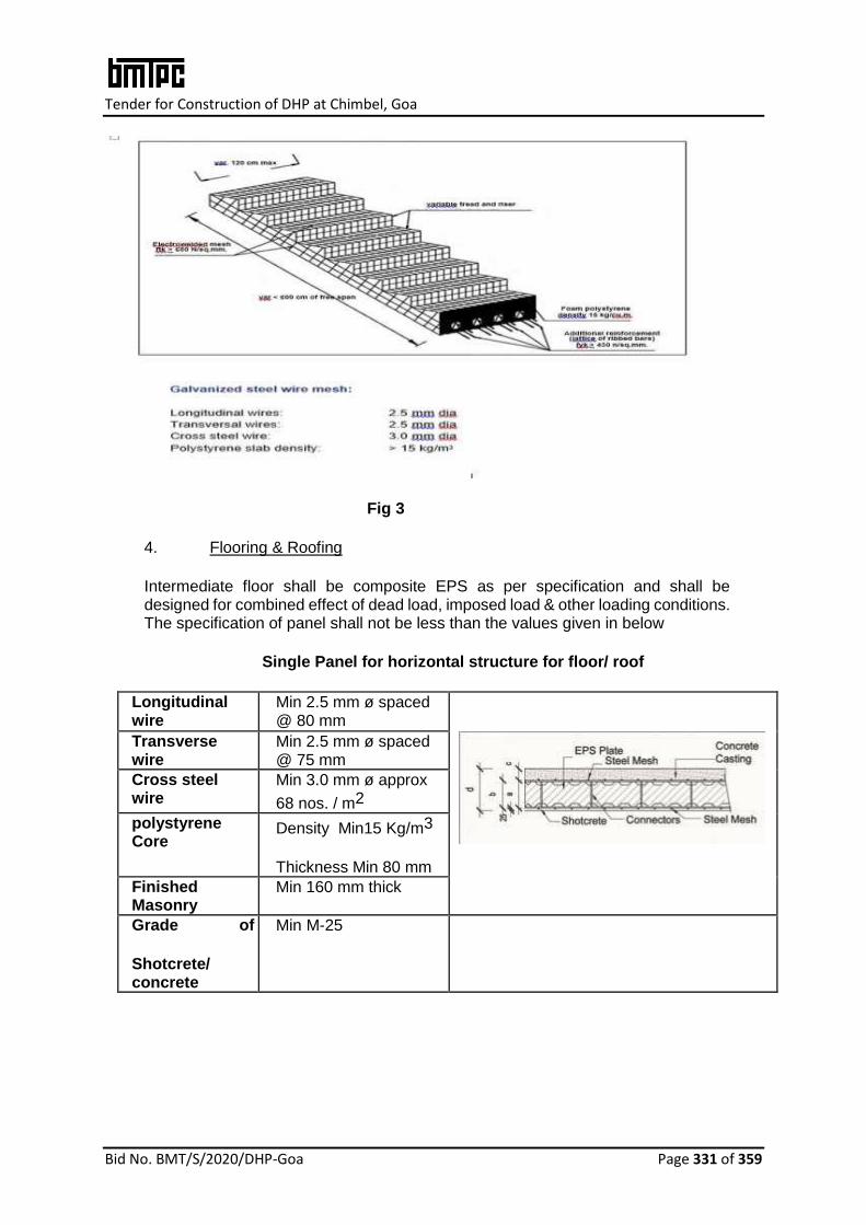
Tender for Construction of DHP at Chimbel, Goa
Bid No. BMT/S/2020/DHP-Goa Page 331 of 359
Fig 3
4. Flooring & Roofing
Intermediate floor shall be composite EPS as per specification and shall be designed for combined effect of dead load, imposed load & other loading conditions. The specification of panel shall not be less than the values given in below
Single Panel for horizontal structure for floor/ roof
Longitudinal wire
Min 2.5 mm ø spaced @ 80 mm
Transverse wire
Min 2.5 mm ø spaced @ 75 mm
Cross steel wire
Min 3.0 mm ø approx
68 nos. / m2
polystyrene Core
Density Min15 Kg/m3
Thickness Min 80 mm
Finished Masonry
Min 160 mm thick
Grade of
Shotcrete/ concrete
Min M-25
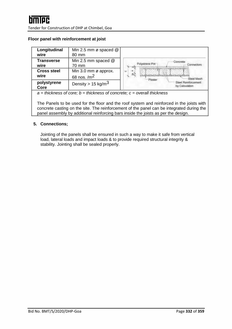
Tender for Construction of DHP at Chimbel, Goa
Bid No. BMT/S/2020/DHP-Goa Page 332 of 359
Floor panel with reinforcement at joist
Longitudinal wire
Min 2.5 mm ø spaced @ 80 mm
Transverse wire
Min 2.5 mm spaced @ 70 mm
Cross steel wire
Min 3.0 mm ø approx.
68 nos. /m2
polystyrene Core
Density > 15 kg/m3
a = thickness of core; b = thickness of concrete; c = overall thickness
The Panels to be used for the floor and the roof system and reinforced in the joists with concrete casting on the site. The reinforcement of the panel can be integrated during the panel assembly by additional reinforcing bars inside the joists as per the design.
5. Connections;
Jointing of the panels shall be ensured in such a way to make it safe from vertical load, lateral loads and impact loads & to provide required structural integrity & stability. Jointing shall be sealed properly.
Tender for Construction of DHP at Chimbel, Goa
Bid No. BMT/S/2020/DHP-Goa Page 333 of 359
D-2) EPS CEMENT SANDWICH PANEL SYSTEM
(1. M/s Bhargav Infrastructure Pvt.Ltd, 2. M/s Rising Japa Infra Private Limited)
1. Manufacturing & Fixing of EPS (Beads) based Cement Panel
Providing and fixing in position factory made EPS cement sandwich wall/roof/floor light weight solid core panels made of core material of EPS granule balls/beads (conforming to IS 4671:1984 and shall have density not less than 15 kg per cum) adhesive, cement, sand, flyash and other bonding material in mortar state processed to form in a preset mould. The outer face on both sides of the panels shall be non asbestos fiber cement board conforming to IS 14862:2000 or Calcium silicate board conforming to EN 14306:2009 of 5mm thick each. Panel shall be laid on 6mm thick cement mortar (1 cement: 2 fine sand) mixed with chemical adhesive of 0.5kg per 50kg of cement or shall be preferably fixed into 'C' channel made of 1.2mm thick MS plate screwed/fastenened to the slab/column/beam etc. The panel shall fixed vertically with tongue and groove joint and horizontally locked with steel bar between each other and floors and filled with cement mortar and adhesive. Panels should be used as floor & roofing with additional structural support, steel or RCC depending upon the design. All the operation shall be completed in all respect as per drawings, manufacturers specifications and under the overall direction of Engineer-in-Charge
2. Steel Structural System
Steel structure frame as per design & conforming to IS: 800 shall be used in the construction. U type channels as per manufacturer’s specification should be used to hold the panels with the structure. Additional clips may be welded with the frame pillars and beams to hold the U channel firmly with the pillars/beans and floor, to ensure structural integrity. PU glue may be applied to hold the panels firmly.
All relevant Indian Standards/ requirements of NBC shall be conformed for materials,design ,fabrication and erection.
D-3) Pre-fab PIR (Polyisocyanurate) based Dry Wall Panel System (1. M/s Covestro India Pvt. Ltd.)
1. PIR Dry Wall Pre-Fab Panel raw material & Structural System
Construction with PIR Dry Wall Pre-Fab Panel non-load bearing walling system where two fibre cement boards (FCB) of 10 mm thickness shall be filled with insulation foam material namely Poly Isocyanurate (PIR) in-situ and erected to produce straight to finish walls.
Fibre Cement Board: Shall be 100% asbestos free and of Type A, Category 3 minimum. as stipulated in IS 14862:2000.(ii) Pre-painted Galvanized Iron (PPGI) sheet: Shall be 0.5mm thick and as conform to IS 14246:2013 (iii) Square Hollow Section (SHS)/C Channel: Shall be manufactured from pre-galvanized high tensile steel conforming to IS 277:2003. (iv) Fibre glass mesh: Shall be as per manufacturer specifications. (v) Acrylic based glue: Shall be as per manufacturer specifications. (vi) Galvanized MS screws: Shall be as per manufacturer specifications. (vii) Anchor fasteners: Shall be of 10mm to 12mm dia., 50mm to 75mm length and as per manufacturer specifications. (viii) Premix Putty: Shall conform to IS 419:1967.

Tender for Construction of DHP at Chimbel, Goa
Bid No. BMT/S/2020/DHP-Goa Page 334 of 359
PIR wall being non-loadbearing wall panels shall be supported with Steel Structural frame members as per approved structural design & conforming to IS 800 (Code of practice for general construction in steel).
2. Erection & Installation of Components Erection & Installation of Steel sections in correct & final position with proper line level and plumb at site making all arrangements (i.e cranes, push-pull jacks & all another T & P for lifting Placing & Alignment of elements, as per approved shop drawings and all complete as per the direction of Engineer-in-Charge including all accessories, jointing, grouting complete. The structure shall be complete in all respect with all internal and external finishing as per approved drawings.
3. Floor/Roof
In-situ RCC slab or RCC slab over deck sheet as per design & relevant code shall be provided as per approved drawing.
D-4) Load Bearing Insulated Sandwich Panel System for Walling & Flooring (1. M/s Project Etopia Group)
Brief of Housing System
It is proprietary 4Wall panelised construction system comprising of light weight load bearing insulated panels. The System is sustainable since the panels can be deconstructed & recycled. The system is energy positive (uses solar grids) with no carbon produced from running/operation of the building & it creates more energy than used, feeding back to main building. The system introduces daylight mimicry, creates perfect lighting environment irrespective of rain & shine condition. It has air purification system & smart control.
Specifications of the panel;
S. No. Key Aspects of the system/panel
Values/details
1. Strength Structural loading strength of 825 KN/80 tonne
2. Thermal Value 0.13 U value with light weight panel structure
3. Structural Fire Resistance 66 minutes (40KN)
4. Air Tightness 0.07 l/s/m2
5. Panel Lightness Heaviest panel weighs 97 Kg, meaning it can easily be lifted and transported
6. Hurricane Resistance Can handle/withstand winds exceeding 400 Mph
Structural Requirement

Tender for Construction of DHP at Chimbel, Goa
Bid No. BMT/S/2020/DHP-Goa Page 335 of 359
The structural design calculations should clearly demonstrate structural integrity and stability including connection details. In addition, any other requirements including safety against earthquake need to be ensured by the designer as per prevailing codal requirements. All relevant Indian Standards/ requirement of NBC shall be conformed.
E. MONOLITHIC CONCRETE CONSTRUCTION SYSTEM
(1. M/s Maini Scaffold Systems Pvt. Ltd., 2. M/ KumkangKind India Pvt. Ltd, 3. M/s S-form India Pvt. Ltd., 4. M/s ATS Infrastructure Ltd., 5. M/s Innovative housing & Infrastructure Pvt. Ltd 6. M/s MFS formwork Systems Pvt. Ltd. 7. M/s Knest Manufacturers LLP. 8. M/s Outinord Formworks Pvt. Ltd. 9. M/s Brilliant Etoile)
Aluminium Formwork System (WILL NOT BE CONSIDERED)
The customized Aluminium formwork using grade 5052 aluminium with panel sheets of minimum 4 mm thick shall be used for monolithic construction of RCC members & for extruded sections grade 6061 (Type-6) aluminium shall be used. The panel sheets shall have repetitive usage of 100 times. The form work includes of beam components i.e. beam side panel, prop head for soffit beam, beams soffit panel, beam soffit bulk head and deck components i.e. deck panel, deck prop, prop length, deck mid, soffit length, deck beam bar and wall components i.e. wall panel, rocker, kiker and internal soffit corner, external soffit corner, external corner, internal corner etc., The panels are to be held in position by pin and wedge system that passes through holes in the out side rib of each panel. The tolerance of finished panels to be (-1 mm), and shall conform to IS 14687-1999 (Falsework for concrete structures – Guidelines). Pins and wedges to be made of high grade mild steel.
Modular Tunnel Form Work System
The Modular Tunnelform System shall consist of inverted L- shaped half tunnels (one vertical panel and one horizontal panel) joined together to create a tunnel. These forms are to be made up of factory cut, 80mm x 80 mm angle sections in accordance with the line of building forms. The panels shall be designed based on loading requirements with minimum 3 mm hot dip galvanized steel sheet, stiffened by folded sheet metal sections. All components shall meet relevant Indian Standards.
Structural Design
The structural design of plain & RCC shall be as per IS 456:2000 while IS 13920:2016 (Ductile detailing of reinforced concrete structures subjected to seismic forces -Code of practice) is referred for ductile detailing of reinforced concrete structure. Thickness of wall below plinth level should be minimum 200 mm with double layers reinforcement. The minimum thickness of RCC wall member shall be 120 mm. All relevant Indian Standards/ requirement of NBC shall be conformed.
F STAY IN PLACE FORMWORK SYSTEM
F-1) Expanded-Steel Panel reinforced with all Galvanized Steel Wire-Struts (M/s JK Structures)
Expanded-Steel Panel reinforced with all-galvanised Steel Wire-Struts serving both as the load-bearing steel structure and as the stay-in-place steel formwork filled with EPS-alleviated concrete.

Tender for Construction of DHP at Chimbel, Goa
Bid No. BMT/S/2020/DHP-Goa Page 336 of 359
Construction of monolithic structure completely “on site”, without formwork with 3D galvanized structural steel (as per manufacturer specification) panels assembled and reinforced with interlocked 3D steel studs and then injected with pumped-in and hand-finished EPS (expanded polystyrene) -alleviated concrete (as per approved mix design and manufacturer’s specification) combining in one single process a stay in place formwork with embedded columns and beams and bracing system. The EPS alleviated concrete is concrete produced with EPS beads. Erection & installation of the structure in correct & final position with proper line level and plumb at site making all necessary accessories & arrangements. per approved drawings and all complete as per the direction of Engineer-in-Charge including all accessories, jointing, grouting complete. The structure shall be complete in all respect with all internal and external finishing as per approved drawings. All relevant Indian Standards/ requirement of NBC shall be conformed
F-2) GFRG Panel Building System (M/s FACT RCF Building Products Limited)
1. Providing & Erecting GFRG Panels
Standard quality GFRG panel of 124 mm thickness with modular cavities procured from GFRG panel manufacturing plant in the country, cut to required wall sizes and floor/ roof slab sizes in correct length and height, including cutting of door, window and ventilator opening as per the cutting drawing prepared by architects /design engineers for the construction of GFRG building and loaded in stillages for transportation to the construction site. Panels to be unloading at site using suitable fork lift/ crane. Erection of GFRG Panels in walls in all floors using suitable crane as per instructions of Engineer-in-Charge, as per cutting drawings and structural drawings, in perfect line and plumb, above RCC plinth beam/GFRG panel below and provide necessary lateral/ slanting support to keep the wall panel in safe position, providing & tieing of Reinforcement as per structural drawings and applying a coat of water repellant coating Zycosil/equivalent or equivalent product (1 Zycosil/equivalent compound: 10 water ) to saturation level over RCC plinth beam to provide water proofing treatment to joint between wall panel & plinth beam to make it sealed completely.
Note:
i. When cutting panel, “A” side is to be for outside or external surface of respective
external wall and B side is to be for internal surface of wall ii. Erection of panel is to be with reference to both building plan & cutting drawing by
following notational mark indicated in the cutting drawing as well as notional mark written on each panel cut as per cutting drawing
2. Filling of empty cavities
Filling of empty cavities (as shown in the structural design drawing) with quarry dust mixed with 5% cement (by volume). After initial infill of 50 mm thick with M25 concrete at base/bottom of cavities to seal off, infill wall panel cavities in 3 stages as detailed below, i. 1st pour / infill to be limited to 0.3 to 0.50 m height from bottom of the panel.
ii. 2nd Pour/ infill: infilling shall be done only after 90 minutes interval between successive pours. The maximum height of infill shall be restricted to 1.5m height or up to the top level of door / window.
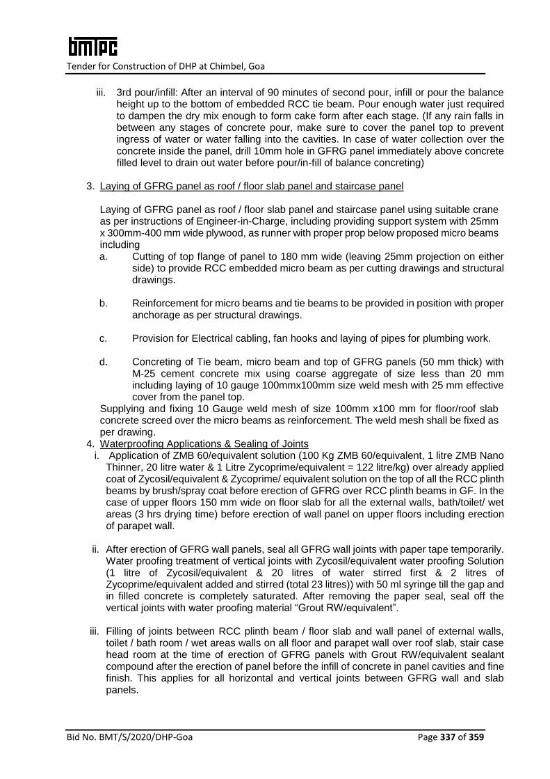
Tender for Construction of DHP at Chimbel, Goa
Bid No. BMT/S/2020/DHP-Goa Page 337 of 359
iii. 3rd pour/infill: After an interval of 90 minutes of second pour, infill or pour the balance height up to the bottom of embedded RCC tie beam. Pour enough water just required to dampen the dry mix enough to form cake form after each stage. (If any rain falls in between any stages of concrete pour, make sure to cover the panel top to prevent ingress of water or water falling into the cavities. In case of water collection over the concrete inside the panel, drill 10mm hole in GFRG panel immediately above concrete filled level to drain out water before pour/in-fill of balance concreting)
3. Laying of GFRG panel as roof / floor slab panel and staircase panel
Laying of GFRG panel as roof / floor slab panel and staircase panel using suitable crane as per instructions of Engineer-in-Charge, including providing support system with 25mm x 300mm-400 mm wide plywood, as runner with proper prop below proposed micro beams including a. Cutting of top flange of panel to 180 mm wide (leaving 25mm projection on either
side) to provide RCC embedded micro beam as per cutting drawings and structural drawings.
b. Reinforcement for micro beams and tie beams to be provided in position with proper
anchorage as per structural drawings. c. Provision for Electrical cabling, fan hooks and laying of pipes for plumbing work. d. Concreting of Tie beam, micro beam and top of GFRG panels (50 mm thick) with
M-25 cement concrete mix using coarse aggregate of size less than 20 mm including laying of 10 gauge 100mmx100mm size weld mesh with 25 mm effective cover from the panel top.
Supplying and fixing 10 Gauge weld mesh of size 100mm x100 mm for floor/roof slab concrete screed over the micro beams as reinforcement. The weld mesh shall be fixed as per drawing.
4. Waterproofing Applications & Sealing of Joints i. Application of ZMB 60/equivalent solution (100 Kg ZMB 60/equivalent, 1 litre ZMB Nano
Thinner, 20 litre water & 1 Litre Zycoprime/equivalent = 122 litre/kg) over already applied coat of Zycosil/equivalent & Zycoprime/ equivalent solution on the top of all the RCC plinth beams by brush/spray coat before erection of GFRG over RCC plinth beams in GF. In the case of upper floors 150 mm wide on floor slab for all the external walls, bath/toilet/ wet areas (3 hrs drying time) before erection of wall panel on upper floors including erection of parapet wall.
ii. After erection of GFRG wall panels, seal all GFRG wall joints with paper tape temporarily.
Water proofing treatment of vertical joints with Zycosil/equivalent water proofing Solution (1 litre of Zycosil/equivalent & 20 litres of water stirred first & 2 litres of Zycoprime/equivalent added and stirred (total 23 litres)) with 50 ml syringe till the gap and in filled concrete is completely saturated. After removing the paper seal, seal off the vertical joints with water proofing material “Grout RW/equivalent”.
iii. Filling of joints between RCC plinth beam / floor slab and wall panel of external walls,
toilet / bath room / wet areas walls on all floor and parapet wall over roof slab, stair case head room at the time of erection of GFRG panels with Grout RW/equivalent sealant compound after the erection of panel before the infill of concrete in panel cavities and fine finish. This applies for all horizontal and vertical joints between GFRG wall and slab panels.
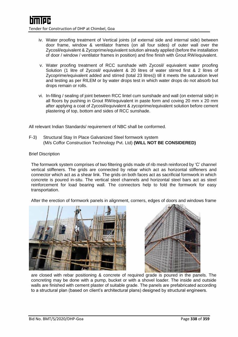
Tender for Construction of DHP at Chimbel, Goa
Bid No. BMT/S/2020/DHP-Goa Page 338 of 359
iv. Water proofing treatment of Vertical joints (of external side and internal side) between door frame, window & ventilator frames (on all four sides) of outer wall over the Zycosil/equivalent & Zycoprime/equivalent solution already applied (before the installation of door / window / ventilator frames in position) and fine finish with Grout RW/equivalent.
v. Water proofing treatment of RCC sunshade with Zycosil/ equivalent water proofing
Solution (1 litre of Zycosil/ equivalent & 20 litres of water stirred first & 2 litres of Zycoprime/equivalent added and stirred (total 23 litres)) till it meets the saturation level and testing as per RILEM or by water drops test in which water drops do not absorb but drops remain or rolls.
vi. In-filling / sealing of joint between RCC lintel cum sunshade and wall (on external side) in
all floors by pushing in Grout RW/equivalent in paste form and coving 20 mm x 20 mm after applying a coat of Zycosil/equivalent & zycoprime/equivalent solution before cement plastering of top, bottom and sides of RCC sunshade.
All relevant Indian Standards/ requirement of NBC shall be conformed.
F-3) Structural Stay In Place Galvanized Steel formwork system
(M/s Coffor Construction Technology Pvt. Ltd) (WILL NOT BE CONSIDERED)
Brief Discription
The formwork system comprises of two filtering grids made of rib mesh reinforced by ‘C’ channel vertical stiffeners. The grids are connected by rebar which act as horizontal stiffeners and connector which act as a shear link. The grids on both faces act as sacrificial formwork in which concrete is poured in-situ. The vertical steel channels and horizontal steel bars act as steel reinforcement for load bearing wall. The connectors help to fold the formwork for easy transportation.
After the erection of formwork panels in alignment, corners, edges of doors and windows frame
are closed with rebar positioning & concrete of required grade is poured in the panels. The concreting may be done with a pump, bucket or with a shovel loader. The inside and outside walls are finished with cement plaster of suitable grade. The panels are prefabricated according to a structural plan (based on client’s architectural plans) designed by structural engineers.
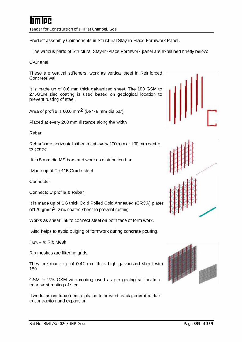
Tender for Construction of DHP at Chimbel, Goa
Bid No. BMT/S/2020/DHP-Goa Page 339 of 359
Product assembly Components in Structural Stay-in-Place Formwork Panel:
The various parts of Structural Stay-in-Place Formwork panel are explained briefly below:
C-Chanel
These are vertical stiffeners, work as vertical steel in Reinforced Concrete wall
It is made up of 0.6 mm thick galvanized sheet. The 180 GSM to 275GSM zinc coating is used based on geological location to prevent rusting of steel.
Area of profile is 60.6 mm2 (i.e > 8 mm dia bar)
Placed at every 200 mm distance along the width
Rebar
Rebar’s are horizontal stiffeners at every 200 mm or 100 mm centre to centre
It is 5 mm dia MS bars and work as distribution bar.
Made up of Fe 415 Grade steel
Connector
Connects C profile & Rebar.
It is made up of 1.6 thick Cold Rolled Cold Annealed (CRCA) plates
of120 gm/m2 zinc coated sheet to prevent rusting
Works as shear link to connect steel on both face of form work.
Also helps to avoid bulging of formwork during concrete pouring.
Part – 4: Rib Mesh
Rib meshes are filtering grids.
They are made up of 0.42 mm thick high galvanized sheet with 180
GSM to 275 GSM zinc coating used as per geological location to prevent rusting of steel
It works as reinforcement to plaster to prevent crack generated due to contraction and expansion.

Tender for Construction of DHP at Chimbel, Goa
Bid No. BMT/S/2020/DHP-Goa Page 340 of 359
Panel
Type T
mm A
mm B
mm W
mm H
mm C10 100 200 100, 200 300,
500,
700,
900,
1100
Min.
500
then
in multiples
of 100
C14 140 200 100, 200 C16 160 200 100, 200 C20 200 200 100, 200 C25 250 200 100, 200
Also provide good bonding to plaster
Size and Types of Panels
Panels are normally produced in sizes as given below (See Fig. 2): Width (W): 300mm, 500mm, 700mm, 900mm & 1100mm Height (H): 500mm to 5000mm in multiples of 100 mm. Thickness (T): 100mm, 140mm, 160mm, 200mm & 250mm. However, customized sizes also be made available on demand.
Fig.2
Types of panels are given below:
i. Standard single panels – These panels shall be used for slab shuttering but may also be used as shuttering option for RCC wall having thickness of more than 350mm. (Fig. 3)
ii. Double panels – Double panels shall have inbuilt steel and not require extra reinforcement. In double panels, the grids shall be connected by articulated rebar loops and connectors that fold.
These panels are of two types:
a. Standard double panels shall be of fixed size and need to be cut on site for openings etc.
b. Customized double panels from the factory shall have required cutting for openings as per drawing and there is no need for cutting on site.
c. These panels create a monolithic structure as it allows pouring of walls and slab together. These panels shall be used for load bearing walls, retaining walls and shear walls. (Fig. 4)
iii. Insulated Double panel – These panels shall have an integrated insulation on the exterior side. The insulated material shall be of polystyrene or polyurethane of required thickness as per design.(Fig. 5)
iv. Fiber Cement Double panel – These panels shall have its interior face as fibre cement board which has smooth surface and avoid plastering of walls. (Fig.6). These panels may be used for water retaining structures.
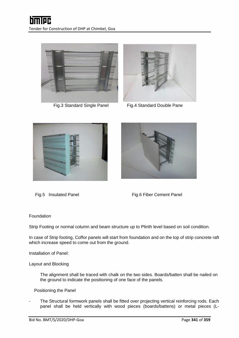
Tender for Construction of DHP at Chimbel, Goa
Bid No. BMT/S/2020/DHP-Goa Page 341 of 359
Fig.3 Standard Single Panel Fig.4 Standard Double Pane
Fig.5 Insulated Panel Fig.6 Fiber Cement Panel
Foundation
Strip Footing or normal column and beam structure up to Plinth level based on soil condition.
In case of Strip footing, Coffor panels will start from foundation and on the top of strip concrete raft which increase speed to come out from the ground.
Installation of Panel:
Layout and Blocking
The alignment shall be traced with chalk on the two sides. Boards/batten shall be nailed on the ground to indicate the positioning of one face of the panels.
Positioning the Panel
- The Structural formwork panels shall be fitted over projecting vertical reinforcing rods. Each panel shall be held vertically with wood pieces (boards/battens) or metal pieces (L-
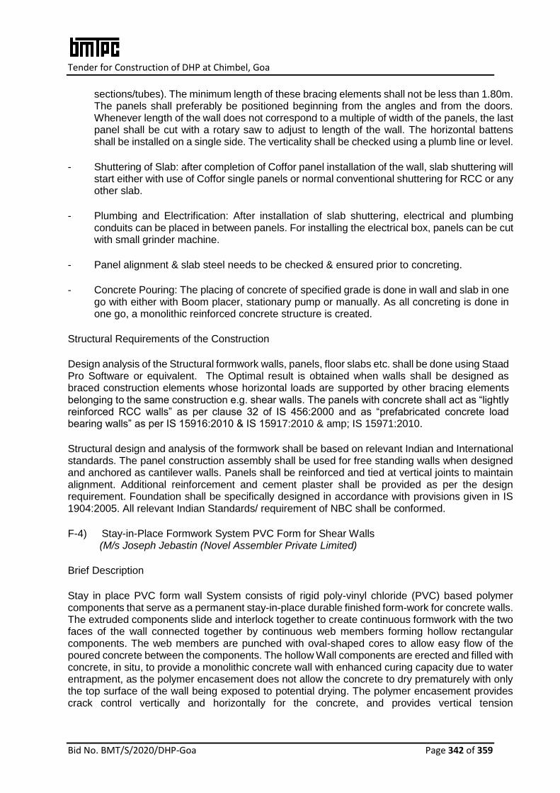
Tender for Construction of DHP at Chimbel, Goa
Bid No. BMT/S/2020/DHP-Goa Page 342 of 359
sections/tubes). The minimum length of these bracing elements shall not be less than 1.80m. The panels shall preferably be positioned beginning from the angles and from the doors. Whenever length of the wall does not correspond to a multiple of width of the panels, the last panel shall be cut with a rotary saw to adjust to length of the wall. The horizontal battens shall be installed on a single side. The verticality shall be checked using a plumb line or level.
- Shuttering of Slab: after completion of Coffor panel installation of the wall, slab shuttering will start either with use of Coffor single panels or normal conventional shuttering for RCC or any other slab.
- Plumbing and Electrification: After installation of slab shuttering, electrical and plumbing conduits can be placed in between panels. For installing the electrical box, panels can be cut with small grinder machine.
- Panel alignment & slab steel needs to be checked & ensured prior to concreting.
- Concrete Pouring: The placing of concrete of specified grade is done in wall and slab in one go with either with Boom placer, stationary pump or manually. As all concreting is done in one go, a monolithic reinforced concrete structure is created.
Structural Requirements of the Construction
Design analysis of the Structural formwork walls, panels, floor slabs etc. shall be done using Staad Pro Software or equivalent. The Optimal result is obtained when walls shall be designed as braced construction elements whose horizontal loads are supported by other bracing elements belonging to the same construction e.g. shear walls. The panels with concrete shall act as “lightly reinforced RCC walls” as per clause 32 of IS 456:2000 and as “prefabricated concrete load bearing walls” as per IS 15916:2010 & IS 15917:2010 & amp; IS 15971:2010.
Structural design and analysis of the formwork shall be based on relevant Indian and International standards. The panel construction assembly shall be used for free standing walls when designed and anchored as cantilever walls. Panels shall be reinforced and tied at vertical joints to maintain alignment. Additional reinforcement and cement plaster shall be provided as per the design requirement. Foundation shall be specifically designed in accordance with provisions given in IS 1904:2005. All relevant Indian Standards/ requirement of NBC shall be conformed.
F-4) Stay-in-Place Formwork System PVC Form for Shear Walls (M/s Joseph Jebastin (Novel Assembler Private Limited)
Brief Description
Stay in place PVC form wall System consists of rigid poly-vinyl chloride (PVC) based polymer components that serve as a permanent stay-in-place durable finished form-work for concrete walls. The extruded components slide and interlock together to create continuous formwork with the two faces of the wall connected together by continuous web members forming hollow rectangular components. The web members are punched with oval-shaped cores to allow easy flow of the poured concrete between the components. The hollow Wall components are erected and filled with concrete, in situ, to provide a monolithic concrete wall with enhanced curing capacity due to water entrapment, as the polymer encasement does not allow the concrete to dry prematurely with only the top surface of the wall being exposed to potential drying. The polymer encasement provides crack control vertically and horizontally for the concrete, and provides vertical tension

Tender for Construction of DHP at Chimbel, Goa
Bid No. BMT/S/2020/DHP-Goa Page 343 of 359
reinforcement thus increasing the structural strength of the wall. Steel dowels are necessary to anchor the wall to the concrete foundation.
Size of Panels Size:
Wall Panels have been developed in various cross-sectional sizes as per project requirement. The common sizes are 64mm, 126mm, 166mm & 206mm. However available wall types are as follow:
Wall components
Wall Thickness
Overall (Nominal)
Concrete Core
Insulation1
N64 64 mm 60 mm 0
N126 126 mm 120 mm 0
N64 walls are erected individually and not preassembled, except for headers and sills.
Pre-assembled walls sections are used for walls over 4300 mm (14') high
The height of walls made with the Formwork vary according to the requirement.
N126 walls less than 4300 mm (14') high are erected individually except for walls of unique projects and for headers and sills.
Panel Components
Main Panel – 250 mm Connector – 158mm

Tender for Construction of DHP at Chimbel, Goa
Bid No. BMT/S/2020/DHP-Goa Page 344 of 359
Connector -33mm Panel – 91mm
Corner Panel 3-WAY (T-CONNECTOR
Jointer Connector Basic Frame
Window Frame Azteca Frame
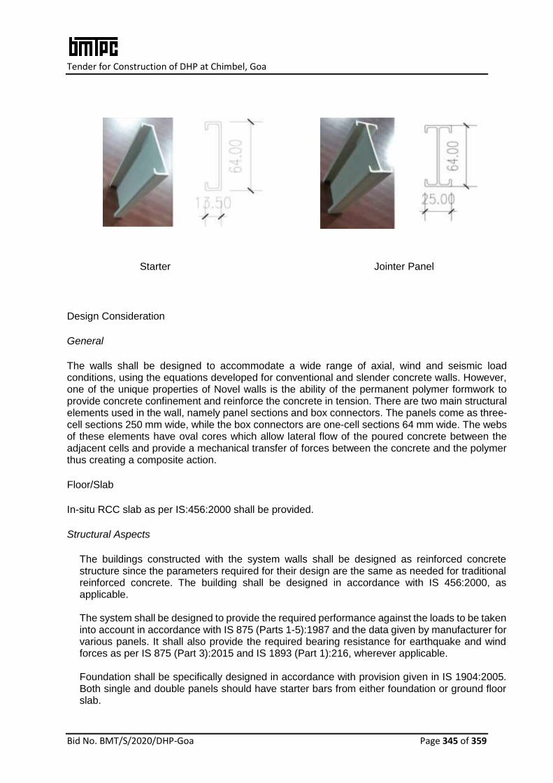
Tender for Construction of DHP at Chimbel, Goa
Bid No. BMT/S/2020/DHP-Goa Page 345 of 359
Starter Jointer Panel
Design Consideration
General
The walls shall be designed to accommodate a wide range of axial, wind and seismic load conditions, using the equations developed for conventional and slender concrete walls. However, one of the unique properties of Novel walls is the ability of the permanent polymer formwork to provide concrete confinement and reinforce the concrete in tension. There are two main structural elements used in the wall, namely panel sections and box connectors. The panels come as three-cell sections 250 mm wide, while the box connectors are one-cell sections 64 mm wide. The webs of these elements have oval cores which allow lateral flow of the poured concrete between the adjacent cells and provide a mechanical transfer of forces between the concrete and the polymer thus creating a composite action.
Floor/Slab
In-situ RCC slab as per IS:456:2000 shall be provided.
Structural Aspects
The buildings constructed with the system walls shall be designed as reinforced concrete structure since the parameters required for their design are the same as needed for traditional reinforced concrete. The building shall be designed in accordance with IS 456:2000, as applicable. The system shall be designed to provide the required performance against the loads to be taken into account in accordance with IS 875 (Parts 1-5):1987 and the data given by manufacturer for various panels. It shall also provide the required bearing resistance for earthquake and wind forces as per IS 875 (Part 3):2015 and IS 1893 (Part 1):216, wherever applicable. Foundation shall be specifically designed in accordance with provision given in IS 1904:2005. Both single and double panels should have starter bars from either foundation or ground floor slab.

Tender for Construction of DHP at Chimbel, Goa
Bid No. BMT/S/2020/DHP-Goa Page 346 of 359
The structural design calculations should clearly demonstrate structural integrity and stability including connection details. In addition, any other requirement regarding safety against earthquake need to be ensured by the designer as per prevailing codal requirements. All relevant Indian Standards/ requirement of NBC shall be conformed.
F-5) Insulating Concrete Forms (ICF) System
(M/s Reliable Insupack Building Solutions)
Insulating concrete Forms (ICF) System comprises of a panel of two walls of Expandable Polystyrene (EPS) separated by a nominal distance of 150mm by hard plastic ties. These are assembled on site to hold reinforced concrete. The forms are open ended hollow polystyrene blocks which fit tightly together to form a shuttering system. Concrete poured into the hollow space to form a continuous wall. When cured, this wall supports the structural loads from floors and roofs, and the shuttering provides thermal insulation. Reinforcing steel shall be as required as per the design parameters. Upper and lower surfaces of the polystyrene panels are castellated and the vertical mating surfaces are tongue-and-groove to form a tight fit when joined together. The rigid formwork does not require supporting falsework. Form locks are used for end stops. The outer surfaces are grooved vertically at 50 mm centres to aid cutting and trimming. Plan view of ICF is shown in Fig. 1.
Fig. 1
Types of Forms
Standard Forms – These form bulk of the forms and have 50mm EPS panels on both sides with hard plastic ties holding the panels. Dimensions of these forms are 1000 x 250 x 250mm. (See Fig. 2)

Tender for Construction of DHP at Chimbel, Goa
Bid No. BMT/S/2020/DHP-Goa Page 347 of 359
Lintel Forms - In combination with Half Height forms, these form the top layer of all wall gaps and hold the concrete thus preventing thermal leaks. Dimensions of these forms are 1000 x 125 x 250mm. (See Fig. 3)
Half Height Forms –Together with the lintel, these form the top layer of all gaps in the wall and hold the required steel reinforcement. Dimensions of these forms are 1000 x 150 x 250mm. (See Fig. 4)
Floor Edge Forms – These form the top most layer, where the wall ends and floor begins. This envelopes the floor slab and thus prevents thermal bridging. Dimensions of these forms are 1000 x 375/125 x 250mm. (See Fig. 5)
Corner Forms – These constitute 90º corner of the building. The two sides are 50mm EPS panels held together with 8 hard ties. Dimensions of these forms are 750/500 x 250 x 250mm. (See Fig. 6)
End Forms – These create wall ending by fitting in inside the Standard or Corner form and provide a smooth and thermal bridge ending to the wall. Dimensions of these forms are 150 x 125 x 50mm. (See Fig. 7)
Fig. 2 Standard Fig. 3 Lintel Fig. 4 Half Height
Fig. 5 Floor Edge Fig. 6 Corner Fig. 7 End
Typical construction
Construction process
The construction of most Insulating Concrete Forms (ICF) & Monolithic Insulated Concrete

Tender for Construction of DHP at Chimbel, Goa
Bid No. BMT/S/2020/DHP-Goa Page 348 of 359
Systems (MICS) buildings is fundamentally a process of stacking lightweight blocks together in a similar manner to building bricks, laying reinforcement where necessary and pouring concrete into the voids of the block work.
Footings
The footings for Insulating Concrete Forms (ICF) & Monolithic Insulated Concrete Systems (MICS) buildings shall be reinforced concrete rafts or strips that are flat and even enough to enable stacking of the form blocks, with reinforcement starter bars set ready to connect with the concrete when poured into the formwork.
Load bearing walls
Any Insulated Concrete System/Forms wall can be designed to be load bearing.
Joints and connections
Joints and connections with other building elements shall be kept to a minimum, especially when the flooring or roofing elements are also made from Insulated Concrete System/Forms.
Fixings
The foam block work or formwork forms a poor basis for any fixings. Light loads are generally carried by the lining or facing materials, such as plasterboard, and heavier loads can be carried by supporting points drilled into the concrete that forms the inner material of the Insulated Concrete System/Forms.
Openings
Major openings for doors, windows, etc., shall be set out in the formwork as it is relatively difficult to make changes later, owing to the fundamentally monolithic nature of the structural elements. Once openings have been made, they can accommodate window and door frames of any type. A typical kind of fixing uses timber blocks set into the ends of the form blocks around the opening.Electrical conduit and plumbing is generally run in chasing in the depth of the form blocks.
Finishes
Finishes are dependent on the materials used to face the Insulated Concrete System/Forms units. Typically, the main finish is a render or render-equivalent covering or paint. Any additional cladding can be added to the Insulating Concrete Forms (ICF) & Monolithic Insulated Concrete Systems (MICS) walls subject to making appropriate sup- ports for it, although many sheet finishes, such as plasterboard, can be glued directly to the surface of the formwork. External renders require a base or skim coat embedded with fibreglass mesh, followed by a second coat and then a texture coating, finally finished with an ‘armour coat’.
RAW MATERIALS
Expanded Polystyrene (EPS): Self-extinguishing type EPS shall conform to IS 4671: 1984 having density not less than 25 kg/m3 and valid Restriction of Hazardous Substance (ROHS) test certification.

Tender for Construction of DHP at Chimbel, Goa
Bid No. BMT/S/2020/DHP-Goa Page 349 of 359
Polyurethane (PU) Foam Adhesive: Shall have Skin Formation of 8 min, Density 25 kg/m³, Sound insulation 58 dB, Insulation factor 35 mW/mK, Shrinkage< 2%, Fire rating B3, Insulation factor 35 mW/m.K and Water absorption of 1 % volume
Plasticizer: Slump retaining super plasticizer for self-compacting plastic concrete (CEMWET SP-3000) shall conform to IS 9103:1999
Hard Plastic Tie: Shall be made with High density polyethylene ensuring stability Cast-in-place concrete: The ingredients, grade of concrete & slump for walls, floors and
roofs shall be used as per IS 456:2000.
Structural Aspects
The Insulating Concrete Forms (ICF) & Monolithic Insulated Concrete Systems (MICS) may be designed using the appropriate design software. The buildings constructed with EPS shall be designed as reinforced concrete structure since the parameters required for their design are the same as needed for traditional reinforced concrete. In the calculation model, the building shall be designed in accordance with IS 456:2000, as applicable, as structure composed of load bearing walls with a box-like structure.
The system shall be designed to provide the required performance against the loads to be taken into account in accordance with IS 875 (Parts 1,2,4&5):1987. It shall also provide the required bearing resistance for earthquake and wind forces as per IS 875 (Part 3):2015 and IS 1893(Part1):2016, wherever applicable. All relevant Indian Standards/ requirement of NBC shall be conformed.
F-6) Building PVC wall material
(M/s Kalzen Realty Pvt. Ltd)
Brief Description
Stay-in-place formwork consisting of hollow‐type rib- reinforced Poly-vinyl chloride (PVC) material comprising of two PVC panel facings with internal PVC ribs, are used as permanent formwork for concrete walls. The web members are punched with cores to allow easy flow of the poured concrete between the components. After putting vertical & horizontal reinforcement as per the design, the hollow Wall components are filled with concrete, in situ, to provide a monolithic concrete wall.
Standard Panels
The standard size of available panels is as follows;
Height Standard panels: 3 meters or 3.3 meters heights
All panels can be ordered to custom height
Minimum 0.5m; Maximum 6m

Tender for Construction of DHP at Chimbel, Goa
Bid No. BMT/S/2020/DHP-Goa Page 350 of 359
Panel width Standard wall panels: 400mm
Half wall panels: 200mm
Quarter panels: 100mm
Thicknesses of Profile 110, 150 and 200 mm
PVC thickness
2.5 mm
PVC density
1,300 kg/m3
Concrete volume 110mm profile: 0.10 cum per sqm
150mm profile: 0.14 cum per sqm
200mm profile: 0.18 cum per sqm
Weight 110mm profile: 18.1 kgs per sqm
150mm profile: 21.6 kgs per sqm
200mm profile: 23 kgs per sqm
The product shall not be affected by exposure to sunlight either in storage or as part of finished product.
Walling System
The wall shall be erected by placing the panels side by side or sliding the new panel down from top and held by using the clipping mechanism. The panel shall have double-hole system ensuring the position of the horizontal and vertical steel reinforcing bars.
The horizontal bars shall be placed along with the laying of panel and vertical bars shall be placed by dropping from top to improve the accuracy and structure of the wall, and minimize variations in the concrete thickness surrounding the reinforcing bars. Once the wall is erected, the plumbing and electrical conducting is done as per the design. After this, concrete of required Garde as per structural design shall be poured into the cavities. Once filled, the system acts as structural element. The external surface shall have specified finish.
Floor/Slab
In-situ RCC slab as per IS:456:2000 shall be provided.
Structural Aspects Wall panel
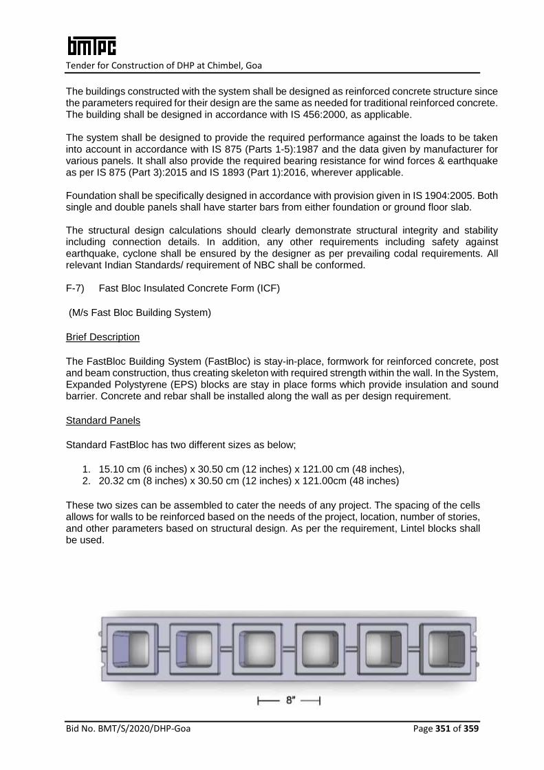
Tender for Construction of DHP at Chimbel, Goa
Bid No. BMT/S/2020/DHP-Goa Page 351 of 359
The buildings constructed with the system shall be designed as reinforced concrete structure since the parameters required for their design are the same as needed for traditional reinforced concrete. The building shall be designed in accordance with IS 456:2000, as applicable. The system shall be designed to provide the required performance against the loads to be taken into account in accordance with IS 875 (Parts 1-5):1987 and the data given by manufacturer for various panels. It shall also provide the required bearing resistance for wind forces & earthquake as per IS 875 (Part 3):2015 and IS 1893 (Part 1):2016, wherever applicable. Foundation shall be specifically designed in accordance with provision given in IS 1904:2005. Both single and double panels shall have starter bars from either foundation or ground floor slab. The structural design calculations should clearly demonstrate structural integrity and stability including connection details. In addition, any other requirements including safety against earthquake, cyclone shall be ensured by the designer as per prevailing codal requirements. All relevant Indian Standards/ requirement of NBC shall be conformed. F-7) Fast Bloc Insulated Concrete Form (ICF)
(M/s Fast Bloc Building System)
Brief Description
The FastBloc Building System (FastBloc) is stay-in-place, formwork for reinforced concrete, post and beam construction, thus creating skeleton with required strength within the wall. In the System, Expanded Polystyrene (EPS) blocks are stay in place forms which provide insulation and sound barrier. Concrete and rebar shall be installed along the wall as per design requirement.
Standard Panels
Standard FastBloc has two different sizes as below;
1. 15.10 cm (6 inches) x 30.50 cm (12 inches) x 121.00 cm (48 inches), 2. 20.32 cm (8 inches) x 30.50 cm (12 inches) x 121.00cm (48 inches)
These two sizes can be assembled to cater the needs of any project. The spacing of the cells allows for walls to be reinforced based on the needs of the project, location, number of stories, and other parameters based on structural design. As per the requirement, Lintel blocks shall be used.
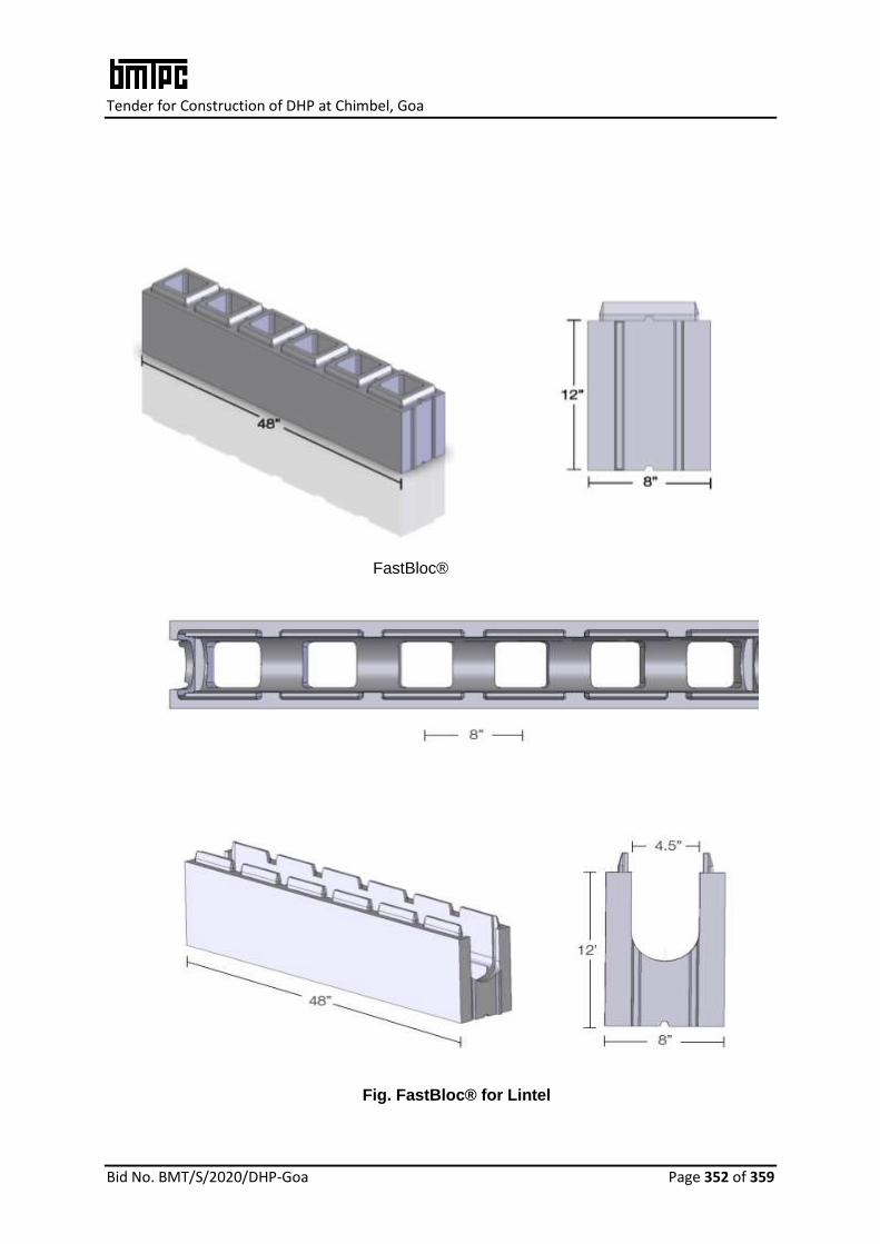
Tender for Construction of DHP at Chimbel, Goa
Bid No. BMT/S/2020/DHP-Goa Page 352 of 359
FastBloc®
Fig. FastBloc® for Lintel

Tender for Construction of DHP at Chimbel, Goa
Bid No. BMT/S/2020/DHP-Goa Page 353 of 359
Walling System
To construct a FastBloc wall, parts shall be assembled similar to "Lego" blocks, by placing the pieces and form walls, known as "reinforced post and beam construction.”
The plugs need to be placed in the cells that do not have vertical rebar reinforcement (per structural calculations), so they are not filled with concrete. The end caps provide an enclosure for the lintel at the end of walls. The vertical cells that are not filled with concrete can be used for electrical and / or plumbing.
Before pouring concrete, end plugs shall also be placed in the lintel beams at the end of walls to seal the blocks horizontally.
Utility Installation
The utilities shall be inserted before filling the walls with concrete. The utilities need to be properly placed in the foundation prior to installation of FastBloc in order to align with the center of the wall and an open FastBloc cell. It is important that the utilities do not interfere with the cells used for concrete and rebar, otherwise the utilities could cause a discontinuity in the concrete and steel and create a cold joint. The large-diameter pipes shall be put outside of the wall. The electrical boxes or load centers are to be placed prior to casting of the walls so they are drowned in concrete. Holes can be cut into FastBloc® walls where utility outlets are required.
Floor/Slab
In-situ RCC slab as per IS:456:2000 shall be provided. Speed floor as per design may also be provided.
Structural Aspects
The buildings constructed with the system walls shall be designed as reinforced concrete structure since the parameters required for their design are the same as needed for traditional reinforced concrete. The building shall be designed in accordance with IS 456:2000, as applicable. Foundation shall be specifically designed in accordance with provision given in IS 1904:2005. When performing the assembly of the foundation, depending on the type, vertical reinforcement rods (rebar) shall necessarily be inserted. The structural design calculations should clearly demonstrate structural integrity and stability including connection details. In addition, any other requirement regarding safety against earthquake, cyclone shall be ensured by the designer as per prevailing codal requirements. All relevant Indian Standards/ requirement of NBC shall be conformed. F-8) Plaswall Panel System
(M/s FTS Buildtech Pvt. Ltd)
Plaswall Panel System is a lost in place formwork, where two fiber cement boards (FCB) of 6mm thickness each and HIMI spacers (High Impact Molded Inserts) bonded between two sheets of FCB (in- situ) are erected to produce straight-to-finish panels. A monolithic structure is then created by filling the entire structure with M20 or higher grade of concrete as per the design.
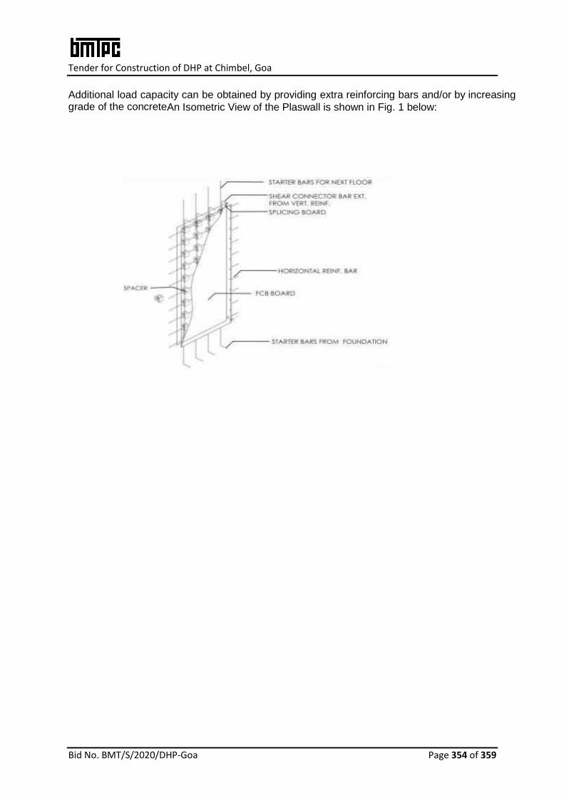
Tender for Construction of DHP at Chimbel, Goa
Bid No. BMT/S/2020/DHP-Goa Page 354 of 359
Additional load capacity can be obtained by providing extra reinforcing bars and/or by increasing grade of the concreteAn Isometric View of the Plaswall is shown in Fig. 1 below:

Tender for Construction of DHP at Chimbel, Goa
Bid No. BMT/S/2020/DHP-Goa Page 355 of 359
SIZE OF PANELS
Panels are normally produced in sizes and dimensions as below:
Length: 2400mm/3000 mm
Width: 1200 mm
Thickness: 87 mm, 112 mm, 137 mm, 162 mm & 230 mm including two fiber cement boards of 6mm thickness each and infill of concrete of 75mm, 100mm,125mm, 150mm and 218mm. The dimensional sketches are shown in
Raw Materials
• Fibre cement board shall be 100% asbestos free and conform to Type A, Category 3 min. as stipulated in IS14862:2000.
• Recycled plastic spacers made of High Impact Molded Inserts shall conform to the specifications of theManufacturer.
• PU Adhesive Glue shall conform to the specifications of the manufacturer.
• Putty shall conform to IS 419:1967.
• Cement, sand, aggregate and reinforcement steel shall be as per the relevant Indian Standards.
Construction, Installation and Jointing Procedure of Plaswall
Foundation
The foundation type as raft, strip, isolated footing shall be decided based on bearing
capacity of the soil, site condition, etc. However, the provision for starter bars for walls
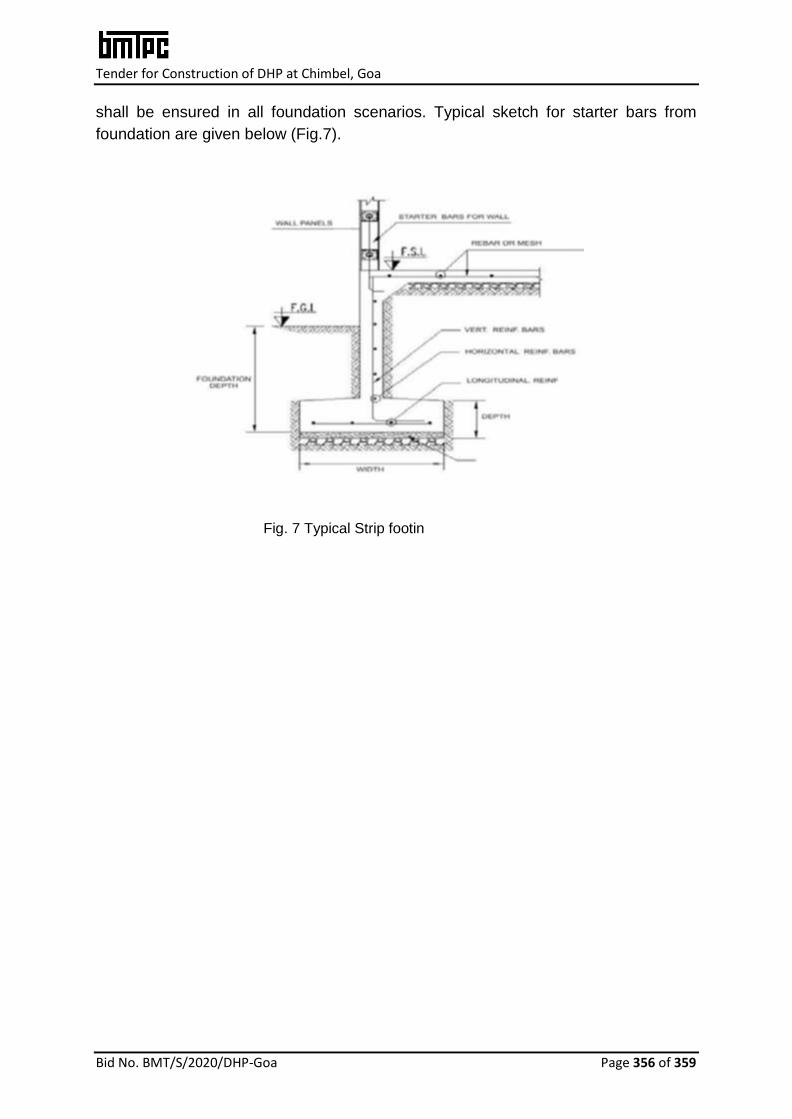
Tender for Construction of DHP at Chimbel, Goa
Bid No. BMT/S/2020/DHP-Goa Page 356 of 359
shall be ensured in all foundation scenarios. Typical sketch for starter bars from
foundation are given below (Fig.7).
Fig. 7 Typical Strip footin

Tender for Construction of DHP at Chimbel, Goa
Bid No. BMT/S/2020/DHP-Goa Page 357 of 359
Panel Installation
Installation
The panel shall be lifted slightly and then placed along the bottom angles. The panel shall be plumbed at edge and face sides with provision of shims, if needed.
• The panel shall be screwed both sides at bottom at 250 mm center to center, while glue is applied & tacky.If glue is not available, spacing shall be kept at 200mm center to center.
• Support the temporarily angle installed on other side of panel to hold it in position for concreting (Fig. 8)
• Corner connection details shall be followed as shown in Fig. 9.
Fig. 8 Diagonal bracing Fig. 9 Corner connection
T-Section
• After installing the primary walls, mark the place where corner will be constructed.
• The joiner stud shall be placed and marked by pencil to have a vertical line reference.
• The joiner stud shall be moved up by 60mm from slab to bottom of joiner stud. The stud hole shall be markedby pencil.
• The marked slots shall be cut by 100mm angle grinder with dry typediamondblade.
• Reinforced dowels shall be prepared, inserted & tied just after screwing thejoiner stud corner connection.(Fig.9)
• In case, the holes intersect with panel stud of the primary wall, the portion of primary stud shall be cut to accommodate the marked holes for T-connection. One 12mm vertical bar shall be provided as replacement.
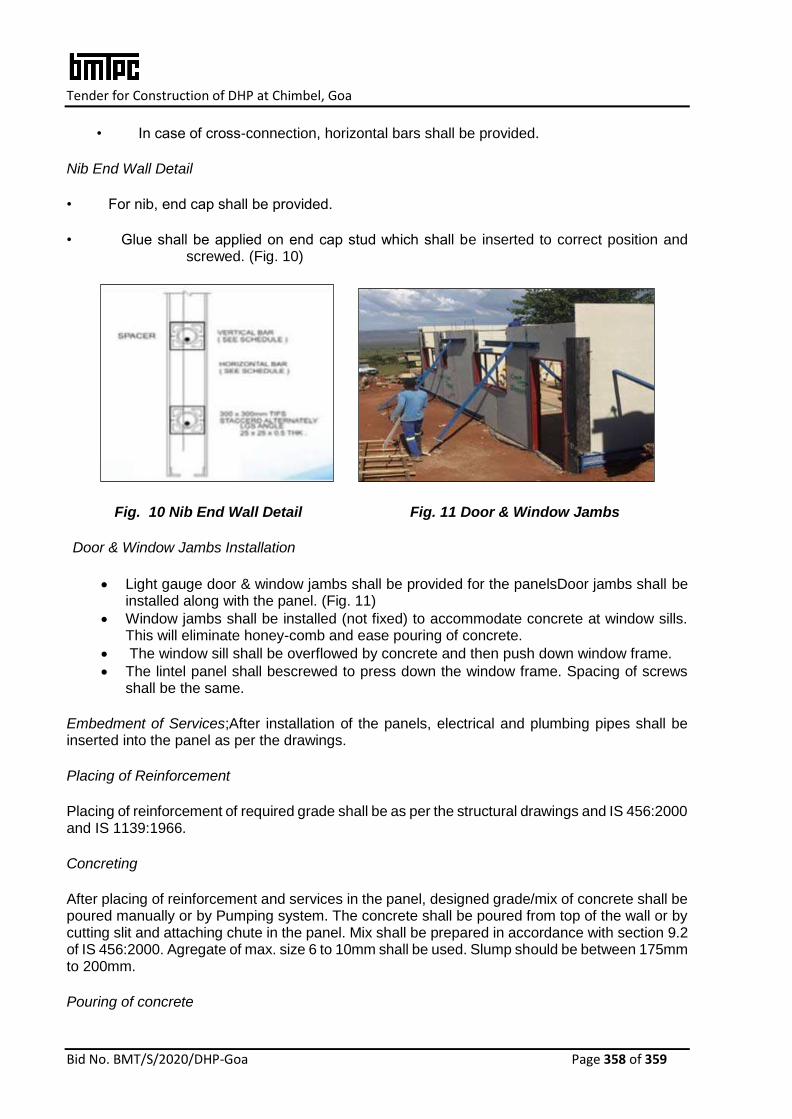
Tender for Construction of DHP at Chimbel, Goa
Bid No. BMT/S/2020/DHP-Goa Page 358 of 359
• In case of cross-connection, horizontal bars shall be provided.
Nib End Wall Detail
• For nib, end cap shall be provided.
• Glue shall be applied on end cap stud which shall be inserted to correct position and screwed. (Fig. 10)
Fig. 10 Nib End Wall Detail Fig. 11 Door & Window Jambs
Door & Window Jambs Installation
Light gauge door & window jambs shall be provided for the panelsDoor jambs shall be installed along with the panel. (Fig. 11)
Window jambs shall be installed (not fixed) to accommodate concrete at window sills. This will eliminate honey-comb and ease pouring of concrete.
The window sill shall be overflowed by concrete and then push down window frame.
The lintel panel shall bescrewed to press down the window frame. Spacing of screws shall be the same.
Embedment of Services;After installation of the panels, electrical and plumbing pipes shall be inserted into the panel as per the drawings.
Placing of Reinforcement
Placing of reinforcement of required grade shall be as per the structural drawings and IS 456:2000 and IS 1139:1966.
Concreting
After placing of reinforcement and services in the panel, designed grade/mix of concrete shall be poured manually or by Pumping system. The concrete shall be poured from top of the wall or by cutting slit and attaching chute in the panel. Mix shall be prepared in accordance with section 9.2 of IS 456:2000. Agregate of max. size 6 to 10mm shall be used. Slump should be between 175mm to 200mm.
Pouring of concrete

Tender for Construction of DHP at Chimbel, Goa
Bid No. BMT/S/2020/DHP-Goa Page 359 of 359
After proper mixing of concrete as per the mix, concrete shall be poured manually into the panel from top of the wall or by cutting slit and attaching chute in the panel. The first pour of concrete should be of 300mm height and after setting, concrete shall be poured up to 800mm as above.
After setting time of each pour of concrete, keep pouring upto 800mm height and continue till height of the wall.
Above process shall be followed horizontally for different walls. This will allow setting time of concrete for the previous wall while the next wall is being poured.
Setting time of concrete shall be min. three hours but during that time other walls shall be poured. Since the project quantum will be big, there will be enough walls available to pour.
Rubber mallet shall be used for tapping the wall while pouring the concrete to avoid honey comb/segregation.
Joint Treatment
After walls are completely filled and mix dried, joint treatment shall be done using fibre mesh tape and putty. (See Figs. 12 & 13)
Fig.12 Yellow Putty with Fibre mesh tape Fig.13 Joint Treatment
Construction of Slab; Once construction of panels is completed, slab construction shall be done as per the structural drawings with wall reinforcement and connection with slab reinforcement. ll relant Indian Standard/ requirement of NBC shall be conformed.