Embed Size (px)
Citation preview
For Small-Statured Adults
Medium External Fixator—Delta FrameAnkle BridgeSurgical Technique
Ankle BridgeAnkle BridgeSurgical TechniqueSurgical Technique

MRI Information
DePuy Synthes Medium External Fixation devices are labeled MR Conditional according to the terminology specified in ASTM F2503-05, Standard Practice for Marking Medical Devices and Other Items for Safety in the Magnetic Resonance Environment.
Nonclinical testing demonstrated that, when used in the specific configurations stated in DePuy Synthes labeling, DePuy Synthes Medium External Fixation devices are MR Conditional. Representative DePuy Synthes Medium External Fixation devices used in a typical construct include clamps, rods and various attachments. A patient with a DePuy Synthes Medium External Fixation frame may be scanned safely after placement of the frame under the following conditions.
Static magnetic field of 1.5 Tesla when the fixation frame is positioned: – 7 cm or less from within the outside edge of the bore of
the MRI at Normal Operating Mode or;
– Completely outside of the MRI bore in First Level Controlled Mode
Static magnetic field of 3.0 Tesla when the fixation frame is positioned: – 7 cm or less from within the outside edge of the bore of
the MRI at Normal Operating Mode or;
– Completely outside of the MRI bore in First Level Controlled Mode
Highest spatial gradient magnetic field of 900 Gauss/cm or less
Maximum MR system reported whole body averaged specific absorption rate (SAR) of 2 W/kg for the Normal Operatinig Mode and 4 W/kg for the First Level Controlled Mode for 15 minutes of scanning
Use only whole body RF transmit coil, no other transmit coils are allowed, local receive only coils are allowed.
Note: In nonclinical testing, the DePuy Synthes external fixation frame was tested in several different configurations. This testing was conducted with the construct positioned 7 cm from within the outside edge of the MRI bore. – The results showed a maximum observed heating for a
wrist fixation frame of 6ºC for 1.5 T and less than 1ºC for 3.0 T with a machine reported whole body averaged SAR of 2 W/kg
Patients may be safely scanned in the MRI chamber at the above conditions. Under such conditions, the maximal expected temperature rise is less than 6ºC. Because higher in vivo heating cannot be excluded, close patient monitoring and communication with the patient during the scan is required. Immediately abort the scan if the patient reports burning sensation or pain. To minimize heating, the scan time should be as short as possible, the SAR as low as possible, and the device should be as far as possible from the edge of the bore. Temperature rise values obtained were based upon a scan time of 15 minutes.
The above field conditions should be compared with those of the user’s MR system, to determine if the item can safely be brought into the user’s MR environment. If placed in the bore of the MR scanner during scanning, DePuy Synthes MR Conditional external fixation devices may have the potential to cause artifact in the diagnostic imaging.
All components of DePuy Synthes external fixation frames must be identified as MR Conditional prior to being placed in or near an MR environment.
Artifact informationMR image quality may be compromised if the area of interest is in the same area or relatively close to the position of the DePuy Synthes Medium External Fixation construct, and it may be necessary to optimize MR imaging parameters, to compensate for the presence of the fixation frame.
Representative devices used to assemble a typical DePuy Synthes Medium External Fixation frame have been evaluated in the MRI chamber and worst-case artifact information is provided below. Overall, artifacts created by DePuy Synthes Medium External Fixation devices may present issues if the MR imaging area of interest is in or near the area where the fixation frame is located. – For FFE sequence: Scan duration: 3 min, TR 100 ms,
TE 15 ms, flip angle 15º and SE sequence: Scan duration: 4 min, TR 500 ms, TE 20 ms, flip angle 70º radio echo sequence, worst-case artifact will extend approximately 10 cm from the device.
Warning – Do not place any radio frequency (RF) transmit coils
over the external fixation frame.
DePuy Synthes Medium External Fixator—Delta Frame Ankle Bridge Surgical Technique
Indications
The DePuy Synthes Medium External Fixation Systemis intended for the construction of an external fixationframe for the treatment of pediatric and adult fractures.
Medium External Fixator—Delta Frame Ankle Bridge Surgical Technique DePuy Synthes 1

Medium External Fixator—Delta Frame Ankle Bridge
When to use The purpose of this frame is to achieve a closed reduction through ligamentotaxis and maintain it until the soft tissue injury can resolve. The frame is recommended in conjunction with a two-stage treatment protocol for extra- and intra-articular fractures of the distal tibia with soft tissue injury (closed or open). The recommended protocol includes immediate open reduction and internal fixation (ORIF) of the fractured fibula, then application of the spanning external fixator in order to maintain tibial reduction, followed by delayed ORIF of the tibia.1-3
Relevant anatomy and pin placement – In the tibia, insert Schanz screws within the safe zone.4
– Tibial Schanz screws should be placed in the AP plane (as shown in the illustrated frame) for maximum stability. Alternatively, they may be placed anteromedially to avoid drilling along the crest.
– Schanz screws are placed proximal to the fracture in the midsagittal plane of the diaphysis, approximately one-half fingerbreadth medial to the tibial crest.
– The proximal Schanz screws should be placed outside the proposed future operative site to avoid the risk of contamination.
– In the calcaneus, a centrally threaded Steinmann pin is placed through the calcaneal tuberosity. To avoid the neurovascular bundle, this pin should be placed well posterior and inferior and can be placed with image intensification. Typically, the ideal insertion site lies two fingerbreadths from the plantar aspect of the heel and two fingerbreadths anterior to the dorsal aspect of the heel.
20°
90°
30°
40°
60°120°
20°
140°
Legend
Optimal zones forSchanz screw insertion
Safe zones forSchanz screw insertion
Tibial Safe Zones5
Calcaneal pin insertion site
1. J. Borrelli, Jr. and L. Catalano. “Open Reduction and Internal Fixation of Pilon Fractures.” Journal of Orthopaedic Trauma. 1999;13;8. 573–582.
2. M. Sirkin et al. “A staged protocol for soft tissue management in the treatment of complex pilon fractures.” Journal of Orthopaedic Trauma. 1999;13;2. 78–84.
3. M.J. Patterson and J.D. Cole. “Two-staged delayed open reduction and internal fixation of severe pilon fractures.” Journal of Orthopaedic Trauma. 1999;13;2. 85–91.
4. F. Behrens and K. Searls. “External Fixation of the Tibia.” Journal of Bone and Joint Surgery. 1986;68-B. 246–254.
5. A. Fernández. “External Fixation.” AO Principles of Fracture Management. T. Rüedi and W. Murphy, ed. Dübendorf, Switzerland; AO Publishing. 2000. 239. Illustration modified and used with permission.
2 DePuy Synthes Medium External Fixator—Delta Frame Ankle Bridge Surgical Technique

DePuy Synthes Medium External Fixation Devices
Warning:– DePuy Synthes self-drilling, self-tapping Schanz screws and
Steinmann pins are not approved for screw attachment or fixation to the posterior elements (pedicles) of the cervical, thoracic, or lumbar spine.
Precautions:– To keep from damaging the femoral cutaneous nerve,
avoid pin insertion up to 15 mm in a dorsal direction from the superior anterior iliac spine.
– When dealing with the humerus, primary consideration should be given to the radial and axillary nerves. Distally, a dorsal approach to the humerus is appropriate. Proximally, it is recommendable to introduce the Schanz screws from a ventrolateral direction, caudal to the path of the axillary nerve.
– Select the appropriate Schanz screw (self-tapping, self-drilling) or Steinmann pin for the patient’s bony anatomy.
– Instruments and screws may have sharp edges or moving joints that may pinch or tear user’s glove or skin.
– Handle devices with care and dispose of worn bone-cutting instruments in an approved sharps container.
– The self-drilling Schanz screw has been developed to minimize heat development. Nevertheless, slow insertion and additional cooling (for example with a Ringer solution) are recommended.
– The tip of the self-drilling Schanz screw should be embedded in the far cortex to effectively resist cantilever forces and to provide sufficient stability.
– Only when bones are osteoporotic does the self-drilling Schanz screw have to be screwed a bit further into the distant cortical bone, and it may even slightly penetrate through it since this can increase anchoring stability.
– The tip of the self-tapping Schanz screw should be embedded in the far cortex to effectively resist cantilever forces and to provide sufficient stability.
– Implant sites should be meticulously cared for to avoid pin-tract infection. Schanz screws and Steinmann pins may be surrounded with antiseptic-coated foam sponges in an effort to avoid infection. An implant-site care procedure should be reviewed with the patient.
– To help minimize the risk of pin-tract infection the following points should be observed:
a. Placement of Schanz screws and Steinmann pins taking anatomy into consideration (ligaments, nerves, arteries).
b. Slow insertion and/or cooling, particularly in dense, hard bone to avoid heat necrosis.
c. Release of skin tension at soft tissue entry point of implant.
Medium External Fixator—Delta Frame Ankle Bridge Surgical Technique DePuy Synthes 3

Recommended Components for Basic Frame
Product Item Quantity Number Needed
390.036 Medium Multi-Pin Clamp, 1 6 position
390.034 Rod Attachment, for Medium 1 Multi-Pin Clamp
390.035 Medium Open Adjustable Clamp 2
395.7xx 8.0 mm Carbon 2 Fiber Rod
394.993 Protective Caps, 4 for 5.0 mm Fixation Pins
395.781 Protective Caps, 4 for 8.0 mm Carbon Fiber Rods
293.xx 5.0 mm Steinmann Pin 1 with Central Thread
294.78x 5.0 mm Self-Drilling 2 Schanz Screw
4 DePuy Synthes Medium External Fixator—Delta Frame Ankle Bridge Surgical Technique

Technique Overview
1Insert Steinmann pin Insert a centrally threaded Steinmann pin through the calcaneal tuberosity.
2Attach open adjustable clamps
3Insert Schanz screwsUse the 6-Position Drill Guide Handle (392.963) or multi-pin clamp technique to ensure proper pin spacing.
4 Attach multi-pin clamp with rod attachment Tighten the vise plates.
5Attach carbon fiber rods
6Reduce fracture Reduce the fracture and tighten all clamps.
Note: For ease of reduction, tighten the proximal clamp first and then reduce.
Lateral x-ray showing frame radiolucency
5
3
4
6
2
1
2
3
Medium External Fixator—Delta Frame Ankle Bridge Surgical Technique DePuy Synthes 5
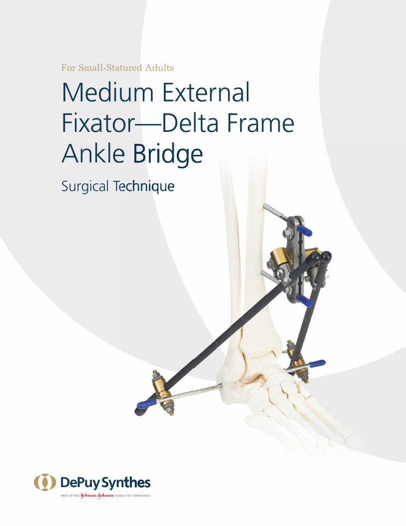
Medium Multi-Pin Clamp Technique
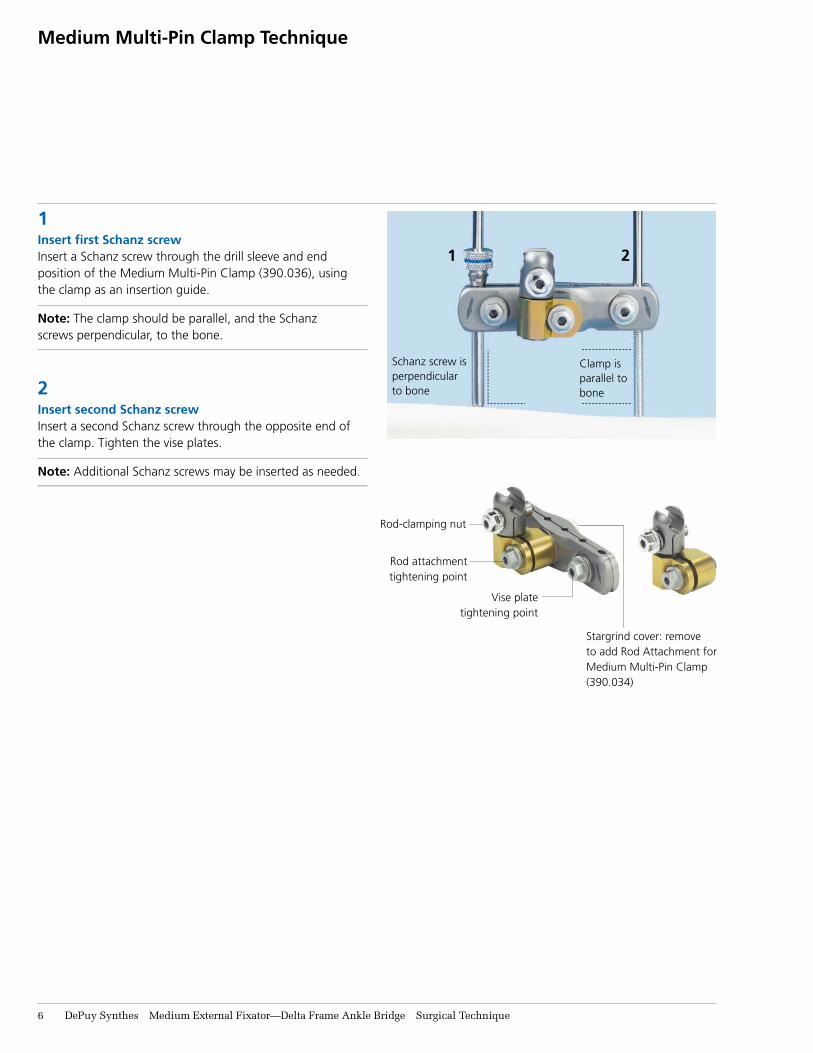
1Insert fi rst Schanz screwInsert a Schanz screw through the drill sleeve and end position of the Medium Multi-Pin Clamp (390.036), using the clamp as an insertion guide.
Note: The clamp should be parallel, and the Schanz screws perpendicular, to the bone.
2Insert second Schanz screwInsert a second Schanz screw through the opposite end of the clamp. Tighten the vise plates.
Note: Additional Schanz screws may be inserted as needed.
1 2
Clamp is parallel to bone
Schanz screw is perpendicular to bone
Vise platetightening point
Stargrind cover: remove to add Rod Attachment for Medium Multi-Pin Clamp (390.034)
Rod-clamping nut
Rod attachment tightening point
6 DePuy Synthes Medium External Fixator—Delta Frame Ankle Bridge Surgical Technique
Optional Frame Configurations
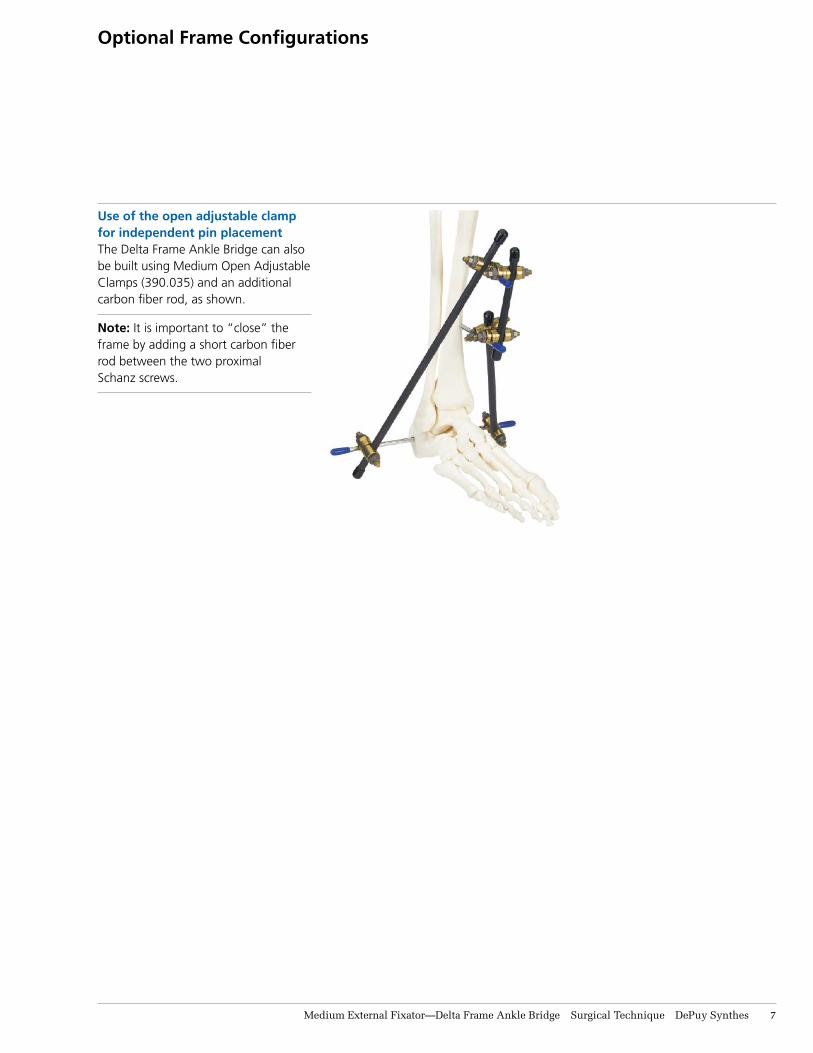
Use of the open adjustable clamp for independent pin placementThe Delta Frame Ankle Bridge can also be built using Medium Open Adjustable Clamps (390.035) and an additional carbon fiber rod, as shown.
Note: It is important to “close” the frame by adding a short carbon fiber rod between the two proximal Schanz screws.
Medium External Fixator—Delta Frame Ankle Bridge Surgical Technique DePuy Synthes 7

Optional Frame Configurations
Enhancing the frame for additional stabilityA 4.5 mm or 5.0 mm Schanz screw can be added medially into the talar neck.
To prevent equinus contracture, several options are available. A 4.0 mm Schanz screw can be placed in the proximal-third portion of the first metatarsal, with a second Schanz screw in the third, fourth or fifth metatarsal. These Schanz screws can each be directly connected to the Delta Frame rods or to each other with a transverse carbon fiber rod. Alternatively, a single Schanz screw can be carefully placed in the middle cuneiform.
Schanz screw in talar neck Schanz screw in metatarsal
The two additional posterior carbon fiber rods act as “kick stands” to elevate the foot, protecting the soft tissues.
8 DePuy Synthes Medium External Fixator—Delta Frame Ankle Bridge Surgical Technique

Graphic Case690.450 Graphic Case, for Medium External Fixator
Implants in Set 01.302.602293.74 5.0 mm Steinmann Pin with Central Thread,
200 mm, 2 ea.
Self-Drilling Schanz Screws, 4 ea.294.777 4.0 mm diameter, 125 mm294.778 4.0 mm diameter, 150 mm294.785 5.0 mm diameter, 175 mm294.786 5.0 mm diameter, 200 mm
Implants in Set 01.302.604293.74 5.0 mm Steinmann Pin with Central Thread,
200 mm, 2 ea.
Titanium Self-Drilling Schanz Screws, 4 ea.494.777 4.0 mm diameter, 125 mm494.778 4.0 mm diameter, 150 mm494.785 5.0 mm diameter, 175 mm494.786 5.0 mm diameter, 200 mm
Instruments (for both sets)310.19 2.0 mm Drill Bit, quick coupling,
100 mm, 2 ea.310.37 3.5 mm Drill Bit, quick coupling,
195 mm, 2 ea.321.158 Combination Wrench, 8 mm width across flats392.955 4.0 mm/2.5 mm Drill Sleeve392.969 Combination T-Wrench, 8 mm 393.101 Drive Adaptor with quick coupling,
for 4.0 mm Schanz Screws 393.103 Drive Adaptor with quick coupling,
for 5.0 mm Schanz Screws393.105 Small Universal Chuck with T-Handle394.181 3.5 mm Trocar, short394.182 3.5 mm Trocar, long394.183 2.5 mm Trocar
Medium External Fixator Set With Self-Drilling Schanz Screws Stainless Steel (01.302.602) or Titanium (01.302.604)
Note: For additional information, please refer to package insert.
For detailed cleaning and sterilizationinstructions, please refer towww.synthes.com/cleaning-sterilization orsterilization instructions, if provided.
Medium External Fixator—Delta Frame Ankle Bridge Surgical Technique DePuy Synthes 9

10 DePuy Synthes Medium External Fixator—Delta Frame Ankle Bridge Surgical Technique
Medium External Fixator Set With Self-Drilling Schanz Screws Stainless Steel (01.302.602) or Titanium (01.302.604)
Also Available Implants Schanz Screws294.43–.48 4.0 mm, spade point, 60 mm–150 mm294.52–.57 5.0 mm, blunted trocar point,
100 mm–250 mm294.71–.76 4.5 mm, blunted trocar point,
80 mm–200 mm
Self-Drilling Schanz Screws294.774–.779 4.0 mm, 60 mm–175 mm294.782–.788 5.0 mm, 100 mm–250 mm
Titanium Self-Drilling Schanz Screws494.774–.779 4.0 mm, 60 mm–175 mm494.782–.788 5.0 mm, 100 mm–250 mm
Steinmann Pins with Central Thread293.64 5.0 mm diameter, 150 mm293.69 5.0 mm diameter, 175 mm
Also Available Instrument03.302.001 Medium Open Compressor392.963 6-Position Drill Guide Handle
Also Available Fixation Material390.026 Medium Pin Clamp, 4 position390.027 Medium Pin Clamp, 6 position390.028 Straight Outrigger Post, 8 mm390.029 30° Outrigger Post, 8 mm390.030 90° Outrigger Post, 8 mm
Also Available Sets105.957 Power Drive Set150.16 ComPact Air Drive II Set
Also Available for Graphic Case690.350.13 Label Sheet Pack, for Schanz Screws
and Carbon Fiber Rods690.451 Label Sheet, for Medium External Fixator clamps
Instruments (for both sets) (continued)395.911 Drill Sleeve Handle395.912 5.0 mm/3.5 mm Drill Sleeve, short395.913 5.0 mm/3.5 mm Drill Sleeve, long395.921 6.0 mm/5.0 mm Threaded Drill Sleeve, short395.922 4.0 mm Threaded Drill Sleeve395.923 6.0 mm/5.0 mm Threaded Drill Sleeve, long
Fixation Material (for both sets)390.031 Medium Combination Clamp, 8 ea.390.032 Dynamization Clip, for Medium Combination
Clamp, 4 ea.390.033 Medium Multi-Pin Clamp, 4 position, 2 ea.390.034 Rod Attachment, for Medium Multi-Pin
Clamp, 4 ea.390.035 Medium Open Adjustable Clamp, 4 ea.390.036 Medium Multi-Pin Clamp, 6 position, 2 ea.390.037 8.0 mm/11.0 mm Combination Clamp, 2 ea.
Protective Caps394.991 4.0 mm Fixation Pins, 1 pkg. of 10394.993 5.0 mm Fixation Pins, 1 pkg. of 10395.781 8.0 mm Carbon Fiber Rods, 4 pkgs. of 2
8.0 mm Carbon Fiber Rods395.779 160 mm, 2 ea.395.782 200 mm395.784 220 mm395.786 240 mm, 2 ea.395.788 280 mm, 2 ea.395.792 320 mm, 2 ea.395.796 360 mm, 2 ea.395.797 400 mm

Limited Warranty and Disclaimer: DePuy Synthes products are sold with a limited warranty to the original purchaser against defects in workmanship and materials. Any other express or implied warranties, including warranties of merchantability or fitness, are hereby disclaimed.
Please also refer to the package insert(s) or other labeling associated with the devices identified in this surgical technique for additional information.
CAUTION: Federal Law restricts these devices to sale by or on the order of a physician.
Some devices listed in this surgical technique may not have been licensed in accordance with Canadian law and may not be for sale in Canada. Please contact your sales consultant for items approved for sale in Canada.
Not all products may currently be available in all markets.
© DePuy Synthes 2004–2017. All rights reserved.DSUS/TRM/1016/1192 6/17 DV
Synthes USA, LLC 1101 Synthes AvenueMonument, CO 80132
Manufactured or distributed by:Synthes USA Products, LLC 1302 Wrights Lane EastWest Chester, PA 19380
To order (USA): 800-523-0322 To order (Canada): 855-946-8999
Note: For recognized manufacturer, refer to the product label.
www.depuysynthes.com