Embed Size (px)
Citation preview
COMPLEX PIPING DESIGN GUIDEFOR SELF-REGULATING HEATING CABLE
THERMONINDUSTRIAL PROCESS HEATING
SOLUTIONS

Introduction ...................................................................... 2Computer Aided Design Program ................................... 2 HEAT TRACING DESIGN OUTLINE ................................ 3
BASIS FOR A GOOD DESIGN ......................................3-12 Step 1: Establish Design Parameters ............................. 3 Step 2: Determine Heat Losses ................................... 4-5 Step 3: Select the Proper Thermon Heating Cable .... 6-10 Step 4: Determine Heat Tracing Circuit Lengths ........... 1 1 Step 5: Choose Options/Accessories ........................... 12
Design Tips .................................................................... 13Design Worksheet ....................................................14-15General Specification ...............................................16-17
This Design Guide displays information in English and metric values wherever possible. Certain tables have been displayed in English values only due to space constraints. Contact Thermon to obtain these tables in metric values.
Complex Piping Design Guide For Self-Regulating Heating Cables
Complex Piping Design GuideFor Self-Regulating Heating Cable
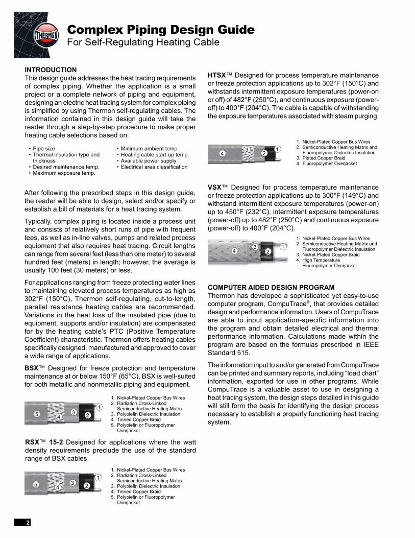
INTRODUCTIONThis design guide addresses the heat tracing requirements of complex piping. Whether the application is a small project or a complete network of piping and equipment, designing an electric heat tracing system for complex piping is simplified by using Thermon self-regulating cables. The information contained in this design guide will take the reader through a step-by-step procedure to make proper heating cable selections based on:
After following the prescribed steps in this design guide, the reader will be able to design, select and/or specify or establish a bill of materials for a heat tracing system.
Typically, complex piping is located inside a process unit and consists of relatively short runs of pipe with frequent tees, as well as in-line valves, pumps and related process equipment that also requires heat tracing. Circuit lengths can range from several feet (less than one meter) to several hundred feet (meters) in length; however, the average is usually 100 feet (30 meters) or less.
For applications ranging from freeze protecting water lines to maintaining elevated process temperatures as high as 302°F (150°C), Thermon self-regulating, cut-to-length, parallel resistance heating cables are recommended. Variations in the heat loss of the insulated pipe (due to equipment, supports and/or insulation) are compensated for by the heating cable’s PTC (Positive Temperature Coefficient) characteristic. Thermon offers heating cables specifically designed, manufactured and approved to cover a wide range of applications.
BSX™ Designed for freeze protection and temperature maintenance at or below 150°F (65°C), BSX is well-suited for both metallic and nonmetallic piping and equipment.
VSX™ Designed for process temperature maintenance or freeze protection applications up to 300°F (149°C) and withstand intermittent exposure temperatures (power-on) up to 450°F (232°C), intermittent exposure temperatures (power-off) up to 482°F (250°C) and continuous exposure (power-off) to 400°F (204°C).
COMPUTER AIDED DESIGN PROGRAMThermon has developed a sophisticated yet easy-to-use computer program, CompuTrace®, that provides detailed design and performance information. Users of CompuTrace are able to input application-specific information into the program and obtain detailed electrical and thermal performance information. Calculations made within the program are based on the formulas prescribed in IEEE Standard 515.
The information input to and/or generated from CompuTrace can be printed and summary reports, including “load chart” information, exported for use in other programs. While CompuTrace is a valuable asset to use in designing a heat tracing system, the design steps detailed in this guide will still form the basis for identifying the design process necessary to establish a properly functioning heat tracing system.
1. Nickel-Plated Copper Bus Wires2. Semiconductive Heating Matrix and
Fluoropolymer Dielectric Insulation3. Nickel-Plated Copper Braid4. High Temperature
Fluoropolymer Overjacket
1. Nickel-Plated Copper Bus Wires2. Radiation Cross-Linked
Semiconductive Heating Matrix3. Polyolefin Dielectric Insulation4. Tinned Copper Braid5. Polyolefin or Fluoropolymer
Overjacket
• Pipe size• Thermal insulation type and
thickness• Desired maintenance temp.• Maximum exposure temp.
• Minimum ambient temp.• Heating cable start-up temp.• Available power supply• Electrical area classification
RSX™ 15-2 Designed for applications where the watt density requirements preclude the use of the standard range of BSX cables.
2
1. Nickel-Plated Copper Bus Wires2. Radiation Cross-Linked
Semiconductive Heating Matrix3. Polyolefin Dielectric Insulation4. Tinned Copper Braid5. Polyolefin or Fluoropolymer
Overjacket
HTSX™ Designed for process temperature maintenance or freeze protection applications up to 302°F (150°C) and withstands intermittent exposure temperatures (power-on or off) of 482°F (250°C), and continuous exposure (power-off) to 400°F (204°C). The cable is capable of withstanding the exposure temperatures associated with steam purging.
11. Nickel-Plated Copper Bus Wires2. Semiconductive Heating Matrix and
Fluoropolymer Dielectric Insulation3. Plated Copper Braid4. Fluoropolymer Overjacket
23
43
21
43 2
15
43 2
15
4
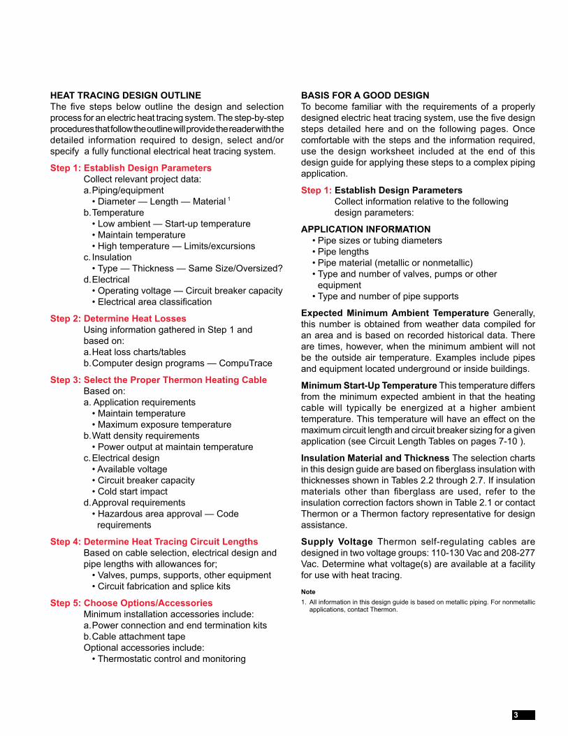
HEAT TRACING DESIGN OUTLINEThe five steps below outline the design and selection process for an electric heat tracing system. The step-by-step procedures that follow the outline will provide the reader with the detailed information required to design, select and/or specify a fully functional electrical heat tracing system.
Step 1: Establish Design Parameters Collect relevant project data: a. Piping/equipment • Diameter — Length — Material 1 b. Temperature • Low ambient — Start-up temperature • Maintain temperature • High temperature — Limits/excursions c. Insulation • Type — Thickness — Same Size/Oversized? d. Electrical • Operating voltage — Circuit breaker capacity • Electrical area classification
Step 2: Determine Heat Losses Using information gathered in Step 1 and based on: a. Heat loss charts/tables b. Computer design programs — CompuTrace
Step 3: Select the Proper Thermon Heating Cable Based on: a. Application requirements • Maintain temperature • Maximum exposure temperature b. Watt density requirements • Power output at maintain temperature c. Electrical design • Available voltage • Circuit breaker capacity • Cold start impact d. Approval requirements • Hazardous area approval — Code
requirements
Step 4: Determine Heat Tracing Circuit Lengths Based on cable selection, electrical design and pipe lengths with allowances for; • Valves, pumps, supports, other equipment • Circuit fabrication and splice kits
Step 5: Choose Options/Accessories Minimum installation accessories include: a. Power connection and end termination kits b. Cable attachment tape Optional accessories include: • Thermostatic control and monitoring
BASIS FOR A GOOD DESIGNTo become familiar with the requirements of a properly designed electric heat tracing system, use the five design steps detailed here and on the following pages. Once comfortable with the steps and the information required, use the design worksheet included at the end of this design guide for applying these steps to a complex piping application.
Step 1: Establish Design Parameters Collect information relative to the following design parameters:
APPLICATION INFORMATION • Pipe sizes or tubing diameters • Pipe lengths • Pipe material (metallic or nonmetallic) • Type and number of valves, pumps or other
equipment • Type and number of pipe supports
Expected Minimum Ambient Temperature Generally, this number is obtained from weather data compiled for an area and is based on recorded historical data. There are times, however, when the minimum ambient will not be the outside air temperature. Examples include pipes and equipment located underground or inside buildings.
Minimum Start-Up Temperature This temperature differs from the minimum expected ambient in that the heating cable will typically be energized at a higher ambient temperature. This temperature will have an effect on the maximum circuit length and circuit breaker sizing for a given application (see Circuit Length Tables on pages 7-10 ).
Insulation Material and Thickness The selection charts in this design guide are based on fiberglass insulation with thicknesses shown in Tables 2.2 through 2.7. If insulation materials other than fiberglass are used, refer to the insulation correction factors shown in Table 2.1 or contact Thermon or a Thermon factory representative for design assistance.
Supply Voltage Thermon self-regulating cables are designed in two voltage groups: 110-130 Vac and 208-277 Vac. Determine what voltage(s) are available at a facility for use with heat tracing.
Note1. All information in this design guide is based on metallic piping. For nonmetallic
applications, contact Thermon.
3
Complex Piping Design GuideFor Self-Regulating Heating Cable
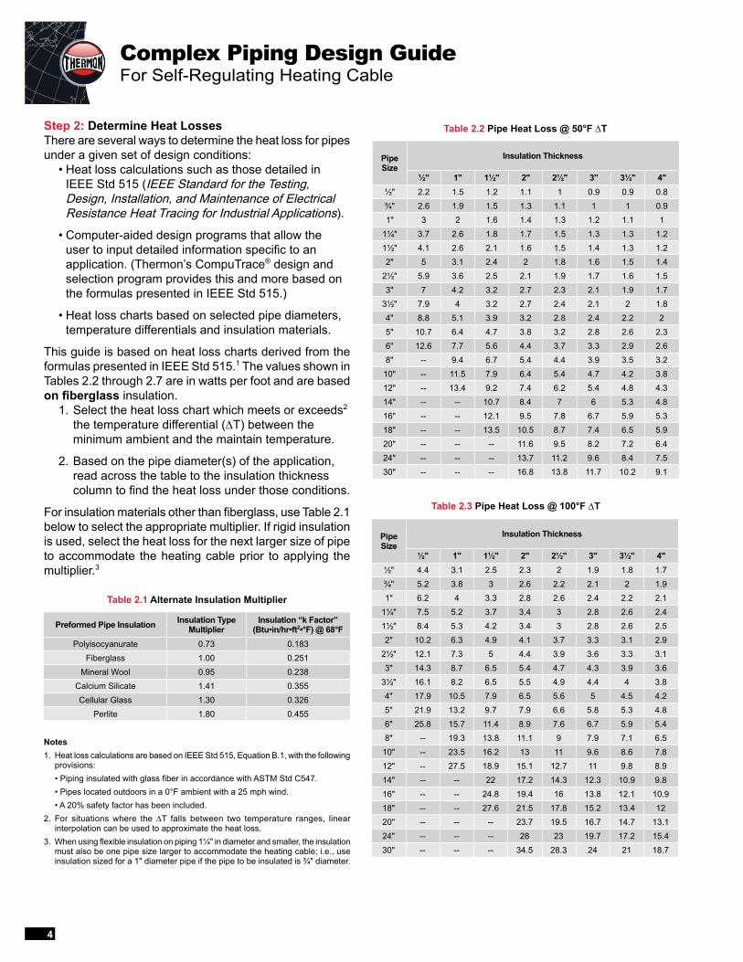
Step 2: Determine Heat LossesThere are several ways to determine the heat loss for pipes under a given set of design conditions: • Heat loss calculations such as those detailed in
IEEE Std 515 (IEEE Standard for the Testing, Design, Installation, and Maintenance of Electrical Resistance Heat Tracing for Industrial Applications).
• Computer-aided design programs that allow the user to input detailed information specific to an application. (Thermon’s CompuTrace® design and selection program provides this and more based on the formulas presented in IEEE Std 515.)
• Heat loss charts based on selected pipe diameters, temperature differentials and insulation materials.
This guide is based on heat loss charts derived from the formulas presented in IEEE Std 515.1 The values shown in Tables 2.2 through 2.7 are in watts per foot and are based on fiberglass insulation. 1. Select the heat loss chart which meets or exceeds2
the temperature differential (∆T) between the minimum ambient and the maintain temperature.
2. Based on the pipe diameter(s) of the application, read across the table to the insulation thickness column to find the heat loss under those conditions.
For insulation materials other than fiberglass, use Table 2.1 below to select the appropriate multiplier. If rigid insulation is used, select the heat loss for the next larger size of pipe to accommodate the heating cable prior to applying the multiplier.3
Notes1. Heat loss calculations are based on IEEE Std 515, Equation B.1, with the following
provisions: • Piping insulated with glass fiber in accordance with ASTM Std C547. • Pipes located outdoors in a 0°F ambient with a 25 mph wind. • A 20% safety factor has been included.2. For situations where the ∆T falls between two temperature ranges, linear
interpolation can be used to approximate the heat loss.3. When using flexible insulation on piping 1¼" in diameter and smaller, the insulation
must also be one pipe size larger to accommodate the heating cable; i.e., use insulation sized for a 1" diameter pipe if the pipe to be insulated is ¾" diameter.
Table 2.2 Pipe Heat Loss @ 50°F ∆T
Table 2.1 Alternate Insulation Multiplier
Table 2.3 Pipe Heat Loss @ 100°F ∆T
Preformed Pipe Insulation Insulation Type Multiplier
Insulation “k Factor” (Btu•in/hr•ft2•°F) @ 68°F
Polyisocyanurate 0.73 0.183Fiberglass 1.00 0.251
Mineral Wool 0.95 0.238Calcium Silicate 1.41 0.355Cellular Glass 1.30 0.326
Perlite 1.80 0.455
Pipe Size
Insulation Thickness
½" 1" 1½" 2" 2½" 3" 3½" 4"½" 2.2 1.5 1.2 1.1 1 0.9 0.9 0.8¾" 2.6 1.9 1.5 1.3 1.1 1 1 0.91" 3 2 1.6 1.4 1.3 1.2 1.1 1
1¼" 3.7 2.6 1.8 1.7 1.5 1.3 1.3 1.21½" 4.1 2.6 2.1 1.6 1.5 1.4 1.3 1.22" 5 3.1 2.4 2 1.8 1.6 1.5 1.4
2½" 5.9 3.6 2.5 2.1 1.9 1.7 1.6 1.53" 7 4.2 3.2 2.7 2.3 2.1 1.9 1.7
3½" 7.9 4 3.2 2.7 2.4 2.1 2 1.84" 8.8 5.1 3.9 3.2 2.8 2.4 2.2 25" 10.7 6.4 4.7 3.8 3.2 2.8 2.6 2.36" 12.6 7.7 5.6 4.4 3.7 3.3 2.9 2.68" -- 9.4 6.7 5.4 4.4 3.9 3.5 3.2
10" -- 11.5 7.9 6.4 5.4 4.7 4.2 3.812" -- 13.4 9.2 7.4 6.2 5.4 4.8 4.314" -- -- 10.7 8.4 7 6 5.3 4.816" -- -- 12.1 9.5 7.8 6.7 5.9 5.318" -- -- 13.5 10.5 8.7 7.4 6.5 5.920" -- -- -- 11.6 9.5 8.2 7.2 6.424" -- -- -- 13.7 11.2 9.6 8.4 7.530" -- -- -- 16.8 13.8 11.7 10.2 9.1
Pipe Size
Insulation Thickness
½" 1" 1½" 2" 2½" 3" 3½" 4"½" 4.4 3.1 2.5 2.3 2 1.9 1.8 1.7¾" 5.2 3.8 3 2.6 2.2 2.1 2 1.91" 6.2 4 3.3 2.8 2.6 2.4 2.2 2.1
1¼" 7.5 5.2 3.7 3.4 3 2.8 2.6 2.41½" 8.4 5.3 4.2 3.4 3 2.8 2.6 2.52" 10.2 6.3 4.9 4.1 3.7 3.3 3.1 2.9
2½" 12.1 7.3 5 4.4 3.9 3.6 3.3 3.13" 14.3 8.7 6.5 5.4 4.7 4.3 3.9 3.6
3½" 16.1 8.2 6.5 5.5 4.9 4.4 4 3.84" 17.9 10.5 7.9 6.5 5.6 5 4.5 4.25" 21.9 13.2 9.7 7.9 6.6 5.8 5.3 4.86" 25.8 15.7 11.4 8.9 7.6 6.7 5.9 5.48" -- 19.3 13.8 11.1 9 7.9 7.1 6.5
10" -- 23.5 16.2 13 11 9.6 8.6 7.812" -- 27.5 18.9 15.1 12.7 11 9.8 8.914" -- -- 22 17.2 14.3 12.3 10.9 9.816" -- -- 24.8 19.4 16 13.8 12.1 10.918" -- -- 27.6 21.5 17.8 15.2 13.4 1220" -- -- -- 23.7 19.5 16.7 14.7 13.124" -- -- -- 28 23 19.7 17.2 15.430" -- -- -- 34.5 28.3 24 21 18.7
4
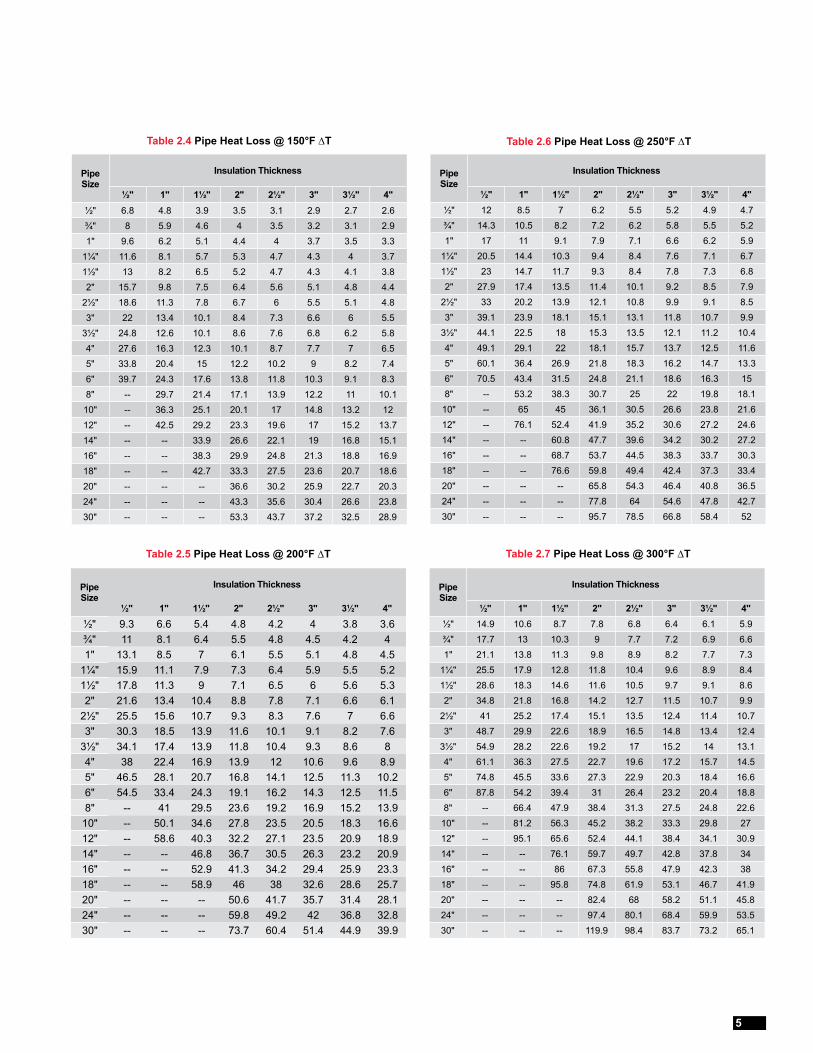
Table 2.4 Pipe Heat Loss @ 150°F ∆T
Table 2.5 Pipe Heat Loss @ 200°F ∆T
Table 2.6 Pipe Heat Loss @ 250°F ∆T
Table 2.7 Pipe Heat Loss @ 300°F ∆T
Pipe Size
Insulation Thickness
½" 1" 1½" 2" 2½" 3" 3½" 4"½" 6.8 4.8 3.9 3.5 3.1 2.9 2.7 2.6¾" 8 5.9 4.6 4 3.5 3.2 3.1 2.91" 9.6 6.2 5.1 4.4 4 3.7 3.5 3.3
1¼" 11.6 8.1 5.7 5.3 4.7 4.3 4 3.71½" 13 8.2 6.5 5.2 4.7 4.3 4.1 3.82" 15.7 9.8 7.5 6.4 5.6 5.1 4.8 4.4
2½" 18.6 11.3 7.8 6.7 6 5.5 5.1 4.83" 22 13.4 10.1 8.4 7.3 6.6 6 5.5
3½" 24.8 12.6 10.1 8.6 7.6 6.8 6.2 5.84" 27.6 16.3 12.3 10.1 8.7 7.7 7 6.55" 33.8 20.4 15 12.2 10.2 9 8.2 7.46" 39.7 24.3 17.6 13.8 11.8 10.3 9.1 8.38" -- 29.7 21.4 17.1 13.9 12.2 11 10.1
10" -- 36.3 25.1 20.1 17 14.8 13.2 1212" -- 42.5 29.2 23.3 19.6 17 15.2 13.714" -- -- 33.9 26.6 22.1 19 16.8 15.116" -- -- 38.3 29.9 24.8 21.3 18.8 16.918" -- -- 42.7 33.3 27.5 23.6 20.7 18.620" -- -- -- 36.6 30.2 25.9 22.7 20.324" -- -- -- 43.3 35.6 30.4 26.6 23.830" -- -- -- 53.3 43.7 37.2 32.5 28.9
Pipe Size
Insulation Thickness
½" 1" 1½" 2" 2½" 3" 3½" 4"½" 9.3 6.6 5.4 4.8 4.2 4 3.8 3.6¾" 11 8.1 6.4 5.5 4.8 4.5 4.2 41" 13.1 8.5 7 6.1 5.5 5.1 4.8 4.5
1¼" 15.9 11.1 7.9 7.3 6.4 5.9 5.5 5.21½" 17.8 11.3 9 7.1 6.5 6 5.6 5.32" 21.6 13.4 10.4 8.8 7.8 7.1 6.6 6.1
2½" 25.5 15.6 10.7 9.3 8.3 7.6 7 6.63" 30.3 18.5 13.9 11.6 10.1 9.1 8.2 7.6
3½" 34.1 17.4 13.9 11.8 10.4 9.3 8.6 84" 38 22.4 16.9 13.9 12 10.6 9.6 8.95" 46.5 28.1 20.7 16.8 14.1 12.5 11.3 10.26" 54.5 33.4 24.3 19.1 16.2 14.3 12.5 11.58" -- 41 29.5 23.6 19.2 16.9 15.2 13.910" -- 50.1 34.6 27.8 23.5 20.5 18.3 16.612" -- 58.6 40.3 32.2 27.1 23.5 20.9 18.914" -- -- 46.8 36.7 30.5 26.3 23.2 20.916" -- -- 52.9 41.3 34.2 29.4 25.9 23.318" -- -- 58.9 46 38 32.6 28.6 25.720" -- -- -- 50.6 41.7 35.7 31.4 28.124" -- -- -- 59.8 49.2 42 36.8 32.830" -- -- -- 73.7 60.4 51.4 44.9 39.9
Pipe Size
Insulation Thickness
½" 1" 1½" 2" 2½" 3" 3½" 4"½" 12 8.5 7 6.2 5.5 5.2 4.9 4.7¾" 14.3 10.5 8.2 7.2 6.2 5.8 5.5 5.21" 17 11 9.1 7.9 7.1 6.6 6.2 5.9
1¼" 20.5 14.4 10.3 9.4 8.4 7.6 7.1 6.71½" 23 14.7 11.7 9.3 8.4 7.8 7.3 6.82" 27.9 17.4 13.5 11.4 10.1 9.2 8.5 7.9
2½" 33 20.2 13.9 12.1 10.8 9.9 9.1 8.53" 39.1 23.9 18.1 15.1 13.1 11.8 10.7 9.9
3½" 44.1 22.5 18 15.3 13.5 12.1 11.2 10.44" 49.1 29.1 22 18.1 15.7 13.7 12.5 11.65" 60.1 36.4 26.9 21.8 18.3 16.2 14.7 13.36" 70.5 43.4 31.5 24.8 21.1 18.6 16.3 158" -- 53.2 38.3 30.7 25 22 19.8 18.1
10" -- 65 45 36.1 30.5 26.6 23.8 21.612" -- 76.1 52.4 41.9 35.2 30.6 27.2 24.614" -- -- 60.8 47.7 39.6 34.2 30.2 27.216" -- -- 68.7 53.7 44.5 38.3 33.7 30.318" -- -- 76.6 59.8 49.4 42.4 37.3 33.420" -- -- -- 65.8 54.3 46.4 40.8 36.524" -- -- -- 77.8 64 54.6 47.8 42.730" -- -- -- 95.7 78.5 66.8 58.4 52
Pipe Size
Insulation Thickness
½" 1" 1½" 2" 2½" 3" 3½" 4"½" 14.9 10.6 8.7 7.8 6.8 6.4 6.1 5.9¾" 17.7 13 10.3 9 7.7 7.2 6.9 6.61" 21.1 13.8 11.3 9.8 8.9 8.2 7.7 7.3
1¼" 25.5 17.9 12.8 11.8 10.4 9.6 8.9 8.41½" 28.6 18.3 14.6 11.6 10.5 9.7 9.1 8.62" 34.8 21.8 16.8 14.2 12.7 11.5 10.7 9.9
2½" 41 25.2 17.4 15.1 13.5 12.4 11.4 10.73" 48.7 29.9 22.6 18.9 16.5 14.8 13.4 12.4
3½" 54.9 28.2 22.6 19.2 17 15.2 14 13.14" 61.1 36.3 27.5 22.7 19.6 17.2 15.7 14.55" 74.8 45.5 33.6 27.3 22.9 20.3 18.4 16.66" 87.8 54.2 39.4 31 26.4 23.2 20.4 18.88" -- 66.4 47.9 38.4 31.3 27.5 24.8 22.6
10" -- 81.2 56.3 45.2 38.2 33.3 29.8 2712" -- 95.1 65.6 52.4 44.1 38.4 34.1 30.914" -- -- 76.1 59.7 49.7 42.8 37.8 3416" -- -- 86 67.3 55.8 47.9 42.3 3818" -- -- 95.8 74.8 61.9 53.1 46.7 41.920" -- -- -- 82.4 68 58.2 51.1 45.824" -- -- -- 97.4 80.1 68.4 59.9 53.530" -- -- -- 119.9 98.4 83.7 73.2 65.1
5
Complex Piping Design GuideFor Self-Regulating Heating Cable
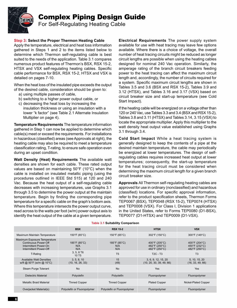
Step 3: Select the Proper Thermon Heating CableApply the temperature, electrical and heat loss information gathered in Steps 1 and 2 to the items listed below to determine which Thermon self-regulating cable is best suited to the needs of the application. Table 3.1 compares numerous product features of Thermon’s BSX, RSX 15-2, HTSX and VSX self-regulating heating cables. Specific cable performance for BSX, RSX 15-2, HTSX and VSX is detailed on pages 7-10.
When the heat loss of the insulated pipe exceeds the output of the desired cable, consideration should be given to: a) using multiple passes of cable, b) switching to a higher power output cable, or c) decreasing the heat loss by increasing the
insulation thickness or using an insulation with a lower “k factor” (see Table 2.1 Alternate Insulation Multiplier on page 4).
Temperature Requirements The temperature information gathered in Step 1 can now be applied to determine which cable(s) meet or exceed the requirements. For installations in hazardous (classified) areas (see Approvals at right), the heating cable may also be required to meet a temperature classification rating, T-rating, to ensure safe operation even during an upset condition.
Watt Density (Heat) Requirements The available watt densities are shown for each cable. These rated output values are based on maintaining 50°F (10°C) when the cable is installed on insulated metallic piping (using the procedures outlined in IEEE Std 515) at 120 and 240 Vac. Because the heat output of a self-regulating cable decreases with increasing temperatures, use Graphs 3.1 through 3.5 to determine the power output at the maintain temperature. Begin by finding the corresponding pipe temperature for a specific cable on the graph’s bottom axis. Where this temperature intersects the power output curve, read across to the watts per foot (w/m) power output axis to identify the heat output of the cable at a given temperature.
Electrical Requirements The power supply system available for use with heat tracing may leave few options available. Where there is a choice of voltage, the overall number of heat tracing circuits might be reduced as longer circuit lengths are possible when using the heating cables designed for nominal 240 Vac operation. Similarly, the amperage rating of the branch circuit breakers feeding power to the heat tracing can affect the maximum circuit length and, accordingly, the number of circuits required for a system. Specific maximum circuit lengths are shown in Tables 3.5 and 3.6 (BSX and RSX 15-2), Tables 3.9 and 3.12 (HTSX), and Tables 3.16 and 3.17 (VSX) based on circuit breaker size and start-up temperature (see Cold Start Impact).
If the heating cable will be energized on a voltage other than 120 or 240 Vac, use Tables 3.3 and 3.4 (BSX and RSX 15-2), Tables 3.8 and 3.11 (HTSX) and Tables 3.14, 3.15 (VSX) to locate the appropriate multiplier. Apply this multiplier to the watt density heat output value established using Graphs 3.1 through 3.4.
Cold Start Impact While a heat tracing system is generally designed to keep the contents of a pipe at the desired maintain temperature, the cable may periodically be energized at lower temperatures. The design of self-regulating cables requires increased heat output at lower temperatures; consequently, the start-up temperature for the heat tracing circuit must be considered when determining the maximum circuit length for a given branch circuit breaker size.
Approvals All Thermon self-regulating heating cables are approved for use in ordinary (nonclassified) and hazardous (classified) locations. For specific approval information, refer to the product specification sheets, Thermon Forms TEP0067 (BSX), TEP0048 (RSX 15-2), TEP0074 (HTSX) and TEP0008 (VSX). For Class I, Division 1 applications in the United States, refer to Forms TEP0080 (D1-BSX), TEP0077 (D1-HTSX) and TEP0009 (D1-VSX).
Table 3.1 Suitability Comparison
BSX RSX 15-2 HTSX VSX
Maximum Maintain Temperature 150°F (65°C) 150°F (65°C) 302°F (150°C) 300°F (149°C)
Maximum Exposure Temperature Continuous Power-Off Intermittent Power-On Intermittent Power-Off
185°F (85°C) N/A N/A
185°F (85°C) N/A N/A
400°F (205°C) 482°F (250°C) 482°F (250°C)
400°F (204°C) 450°F (232°C) 482°F (250°C)
T-Rating 3, 5, 8 T6 10 T5 T5 T2C - T3 T3
Available Watt Densities w/ft @ 50°F (w/m @ 10°C)
3, 5, 8, 10 (10, 16, 26, 33)
15 (49)
3, 6, 9, 12, 15, 20 (10, 20, 30, 39, 49, 66)
5, 10, 15, 20 (16, 33, 49, 66)
Steam Purge Tolerant No No Yes Yes
Dielectric Material Polyolefin Polyolefin Fluoropolymer Fluoropolymer
Metallic Braid Material Tinned Copper Tinned Copper Plated Copper Nickel-Plated Copper
Overjacket Material(s) Polyolefin or Fluoropolymer Polyolefin or Fluoropolymer Fluoropolymer Fluoropolymer
6
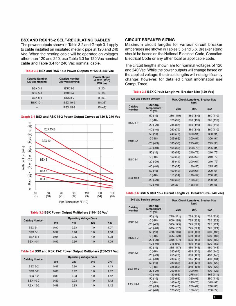
BSX AND RSX 15-2 SELF-REGULATING CABLES The power outputs shown in Table 3.2 and Graph 3.1 apply to cable installed on insulated metallic pipe at 120 and 240 Vac. When the heating cable will be operated on voltages other than 120 and 240, use Table 3.3 for 120 Vac nominal cable and Table 3.4 for 240 Vac nominal cable.
Table 3.2 BSX and RSX 15-2 Power Outputs at 120 & 240 Vac
Graph 3.1 BSX and RSX 15-2 Power Output Curves at 120 & 240 Vac
Watt
s per
Foo
t (W
/m)
4 (13)
6 (20)
Pipe Temperature °F (°C)
0
2 (6)
8 (26)
12 (39)
10 (33)
Table 3.3 BSX Power Output Multipliers (110-130 Vac)
Table 3.4 BSX and RSX 15-2 Power Output Multipliers (208-277 Vac)
CIRCUIT BREAKER SIZING Maximum circuit lengths for various circuit breaker amperages are shown in Tables 3.5 and 3.6. Breaker sizing should be based on the National Electrical Code, Canadian Electrical Code or any other local or applicable code.
The circuit lengths shown are for nominal voltages of 120 and 240 Vac. While the power outputs will change based on the applied voltage, the circuit lengths will not significantly change; however, for detailed circuit information use CompuTrace.
Table 3.5 BSX Circuit Length vs. Breaker Size (120 Vac)
Table 3.6 BSX & RSX 15-2 Circuit Length vs. Breaker Size (240 Vac)
BSX 10
BSX 8
BSX 5
BSX 3
RSX 15-216(52)
18(59)
Catalog Number 120 Vac Nominal
Catalog Number 240 Vac Nominal
Power Output at 50°F (10°C)
W/ft (m)
BSX 3-1 BSX 3-2 3 (10)
BSX 5-1 BSX 5-2 5 (16)
BSX 8-1 BSX 8-2 8 (26)
BSX 10-1 BSX 10-2 10 (33)
-- RSX 15-2 15 (49)
Catalog NumberOperating Voltage (Vac)
110 115 120 130
BSX 3-1 0.90 0.93 1.0 1.07
BSX 5-1 0.92 0.96 1.0 1.08
BSX 8-1 0.91 0.96 1.0 1.08
BSX 10-1 0.92 0.96 1.0 1.08
Catalog NumberOperating Voltage (Vac)
208 220 240 277
BSX 3-2 0.87 0.90 1.0 1.13
BSX 5-2 0.88 0.92 1.0 1.12
BSX 8-2 0.89 0.93 1.0 1.12
BSX 10-2 0.89 0.93 1.0 1.12
RSX 15-2 0.89 0.93 1.0 1.12
120 Vac Service Voltage Max. Circuit Length vs. Breaker Size ft (m)
20A 30A 40A Catalog Number
Start-Up Temperature
°F (°C)
BSX 3-1
50 (10) 360 (110) 360 (110) 360 (110)0 (-18) 325 (99) 360 (110) 360 (110)
-20 (-29) 285 (87) 360 (110) 360 (110)
-40 (-40) 260 (79) 360 (110) 360 (110)
BSX 5-1
50 (10) 240 (73) 300 (91) 300 (91)0 (-18) 205 (62) 300 (91) 300 (91)
-20 (-29) 185 (56) 275 (84) 295 (90)
-40 (-40) 165 (50) 250 (76) 265 (81)
BSX 8-1
50 (10) 190 (58) 240 (73) 240 (73)0 (-18) 150 (46) 225 (69) 240 (73)
-20 (-29) 135 (41) 200 (61) 240 (73)
-40 (-40) 120 (37) 180 (55) 215 (66)
BSX 10-1
50 (10) 160 (49) 200 (61) 200 (61)0 (-18) 110 (34) 170 (52) 200 (61)
-20 (-29) 100 (30) 150 (46) 200 (61)
-40 (-40) 90 (27) 135 (41) 180 (55)
240 Vac Service Voltage Max. Circuit Length vs. Breaker Size ft (m)
20A 30A 40A Catalog Number
Start-Up Temperature
°F (°C)
BSX 3-2
50 (10) 725 (221) 725 (221) 725 (221)0 (-18) 650 (198) 725 (221) 725 (221)
-20 (-29) 575 (175) 725 (221) 725 (221)-40 (-40) 515 (157) 725 (221) 725 (221)
BSX 5-2
50 (10) 480 (146) 600 (183) 600 (183)0 (-18) 395 (120) 590 (180) 600 (183)
-20 (-29) 350 (107) 525 (160) 590 (180)-40 (-40) 315 (96) 475 (145) 530 (162)
BSX 8-2
50 (10) 385 (117) 480 (146) 480 (146)0 (-18) 285 (87) 425 (130) 480 (146)
-20 (-29) 255 (78) 380 (122) 480 (146)-40 (-40) 230 (70) 345 (116) 430 (131)
BSX 10-2
50 (10) 280 (85) 400 (122) 400 (122)0 (-18) 225 (69) 340 (104) 400 (122)
-20 (-29) 200 (61) 300 (91) 400 (122)-40 (-40) 180 (55) 275 (84) 365 (111)
RSX 15-2
50 (10) 205 (63) 320 (98) 380 (116)0 (-18) 145 (45) 225 (70) 315 (97)
-20 (-29) 130 (40) 200 (62) 280 (86)-40 (-40) 120 (36) 180 (55) 250 (77)
30(-1)
50(10)
70(21)
90(32)
11043)
130(54)
150(66)
7
Complex Piping Design GuideFor Self-Regulating Heating Cable
Table 3.8 HTSX Power Output Multipliers (110-130 Vac)
Table 3.9 HTSX Circuit Length vs. Breaker Size (120 Vac)
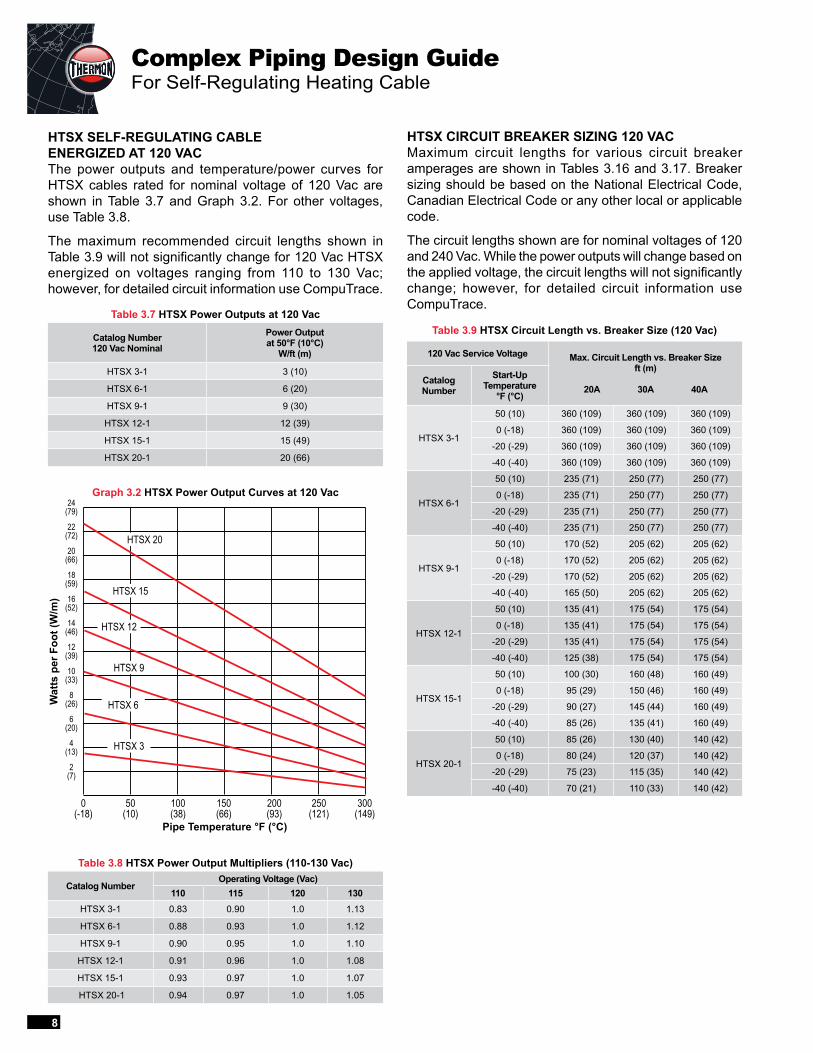
HTSX SELF-REGULATING CABLE ENERGIZED AT 120 VACThe power outputs and temperature/power curves for HTSX cables rated for nominal voltage of 120 Vac are shown in Table 3.7 and Graph 3.2. For other voltages, use Table 3.8.
The maximum recommended circuit lengths shown in Table 3.9 will not significantly change for 120 Vac HTSX energized on voltages ranging from 110 to 130 Vac; however, for detailed circuit information use CompuTrace.
Table 3.7 HTSX Power Outputs at 120 Vac
Graph 3.2 HTSX Power Output Curves at 120 Vac
HTSX CIRCUIT BREAKER SIZING 120 VAC Maximum circuit lengths for various circuit breaker amperages are shown in Tables 3.16 and 3.17. Breaker sizing should be based on the National Electrical Code, Canadian Electrical Code or any other local or applicable code.
The circuit lengths shown are for nominal voltages of 120 and 240 Vac. While the power outputs will change based on the applied voltage, the circuit lengths will not significantly change; however, for detailed circuit information use CompuTrace.
Catalog Number 120 Vac Nominal
Power Output at 50°F (10°C)
W/ft (m)
HTSX 3-1 3 (10)
HTSX 6-1 6 (20)
HTSX 9-1 9 (30)
HTSX 12-1 12 (39)
HTSX 15-1 15 (49)
HTSX 20-1 20 (66)
Catalog NumberOperating Voltage (Vac)
110 115 120 130HTSX 3-1 0.83 0.90 1.0 1.13
HTSX 6-1 0.88 0.93 1.0 1.12
HTSX 9-1 0.90 0.95 1.0 1.10
HTSX 12-1 0.91 0.96 1.0 1.08
HTSX 15-1 0.93 0.97 1.0 1.07
HTSX 20-1 0.94 0.97 1.0 1.05
120 Vac Service Voltage Max. Circuit Length vs. Breaker Size ft (m)
20A 30A 40A Catalog Number
Start-Up Temperature
°F (°C)
HTSX 3-1
50 (10) 360 (109) 360 (109) 360 (109)
0 (-18) 360 (109) 360 (109) 360 (109)
-20 (-29) 360 (109) 360 (109) 360 (109)
-40 (-40) 360 (109) 360 (109) 360 (109)
HTSX 6-1
50 (10) 235 (71) 250 (77) 250 (77)
0 (-18) 235 (71) 250 (77) 250 (77)
-20 (-29) 235 (71) 250 (77) 250 (77)
-40 (-40) 235 (71) 250 (77) 250 (77)
HTSX 9-1
50 (10) 170 (52) 205 (62) 205 (62)
0 (-18) 170 (52) 205 (62) 205 (62)
-20 (-29) 170 (52) 205 (62) 205 (62)
-40 (-40) 165 (50) 205 (62) 205 (62)
HTSX 12-1
50 (10) 135 (41) 175 (54) 175 (54)
0 (-18) 135 (41) 175 (54) 175 (54)
-20 (-29) 135 (41) 175 (54) 175 (54)
-40 (-40) 125 (38) 175 (54) 175 (54)
HTSX 15-1
50 (10) 100 (30) 160 (48) 160 (49)
0 (-18) 95 (29) 150 (46) 160 (49)
-20 (-29) 90 (27) 145 (44) 160 (49)
-40 (-40) 85 (26) 135 (41) 160 (49)
HTSX 20-1
50 (10) 85 (26) 130 (40) 140 (42)
0 (-18) 80 (24) 120 (37) 140 (42)
-20 (-29) 75 (23) 115 (35) 140 (42)
-40 (-40) 70 (21) 110 (33) 140 (42)
Pipe Temperature °F (°C)
Wat
ts p
er F
oot (
W/m
)
8(26)
10(33)
2(7)
6(20)
12(39)
16(52)
18(59)
20(66)
22(72)
24(79)
14(46)
0(-18)
300(149)
50(10)
200(93)
100(38)
250(121)
150(66)
HTSX 20
4(13)
HTSX 15
HTSX 12
HTSX 6
HTSX 9
HTSX 3
8
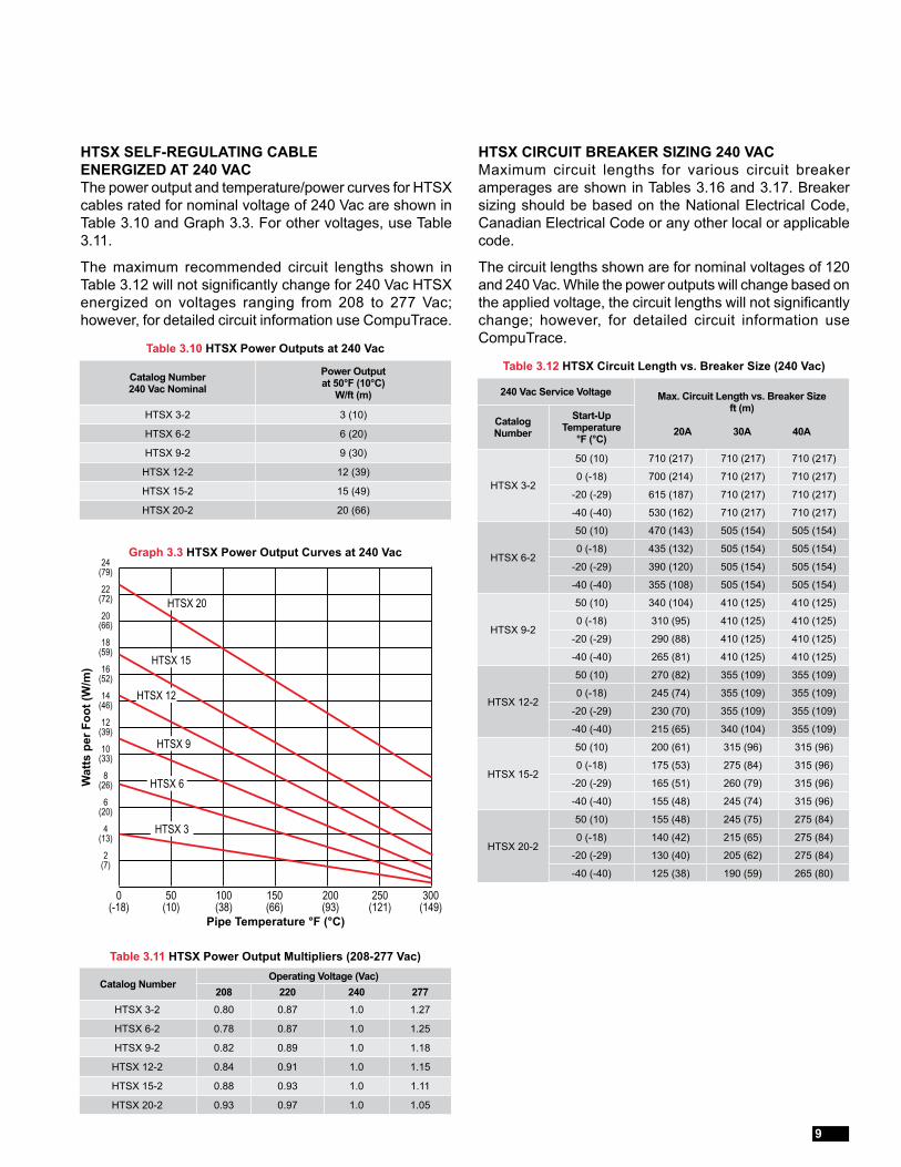
Table 3.11 HTSX Power Output Multipliers (208-277 Vac)
Table 3.12 HTSX Circuit Length vs. Breaker Size (240 Vac)
HTSX CIRCUIT BREAKER SIZING 240 VAC Maximum circuit lengths for various circuit breaker amperages are shown in Tables 3.16 and 3.17. Breaker sizing should be based on the National Electrical Code, Canadian Electrical Code or any other local or applicable code.
The circuit lengths shown are for nominal voltages of 120 and 240 Vac. While the power outputs will change based on the applied voltage, the circuit lengths will not significantly change; however, for detailed circuit information use CompuTrace.
HTSX SELF-REGULATING CABLE ENERGIZED AT 240 VAC The power output and temperature/power curves for HTSX cables rated for nominal voltage of 240 Vac are shown in Table 3.10 and Graph 3.3. For other voltages, use Table 3.11.
The maximum recommended circuit lengths shown in Table 3.12 will not significantly change for 240 Vac HTSX energized on voltages ranging from 208 to 277 Vac; however, for detailed circuit information use CompuTrace.
Table 3.10 HTSX Power Outputs at 240 Vac
Graph 3.3 HTSX Power Output Curves at 240 Vac
Catalog Number 240 Vac Nominal
Power Output at 50°F (10°C)
W/ft (m)
HTSX 3-2 3 (10)
HTSX 6-2 6 (20)
HTSX 9-2 9 (30)
HTSX 12-2 12 (39)
HTSX 15-2 15 (49)
HTSX 20-2 20 (66)
Catalog NumberOperating Voltage (Vac)
208 220 240 277HTSX 3-2 0.80 0.87 1.0 1.27
HTSX 6-2 0.78 0.87 1.0 1.25
HTSX 9-2 0.82 0.89 1.0 1.18
HTSX 12-2 0.84 0.91 1.0 1.15
HTSX 15-2 0.88 0.93 1.0 1.11
HTSX 20-2 0.93 0.97 1.0 1.05
240 Vac Service Voltage Max. Circuit Length vs. Breaker Size ft (m)
20A 30A 40A Catalog Number
Start-Up Temperature
°F (°C)
HTSX 3-2
50 (10) 710 (217) 710 (217) 710 (217)
0 (-18) 700 (214) 710 (217) 710 (217)
-20 (-29) 615 (187) 710 (217) 710 (217)
-40 (-40) 530 (162) 710 (217) 710 (217)
HTSX 6-2
50 (10) 470 (143) 505 (154) 505 (154)
0 (-18) 435 (132) 505 (154) 505 (154)
-20 (-29) 390 (120) 505 (154) 505 (154)
-40 (-40) 355 (108) 505 (154) 505 (154)
HTSX 9-2
50 (10) 340 (104) 410 (125) 410 (125)
0 (-18) 310 (95) 410 (125) 410 (125)
-20 (-29) 290 (88) 410 (125) 410 (125)
-40 (-40) 265 (81) 410 (125) 410 (125)
HTSX 12-2
50 (10) 270 (82) 355 (109) 355 (109)
0 (-18) 245 (74) 355 (109) 355 (109)
-20 (-29) 230 (70) 355 (109) 355 (109)
-40 (-40) 215 (65) 340 (104) 355 (109)
HTSX 15-2
50 (10) 200 (61) 315 (96) 315 (96)
0 (-18) 175 (53) 275 (84) 315 (96)
-20 (-29) 165 (51) 260 (79) 315 (96)
-40 (-40) 155 (48) 245 (74) 315 (96)
HTSX 20-2
50 (10) 155 (48) 245 (75) 275 (84)
0 (-18) 140 (42) 215 (65) 275 (84)
-20 (-29) 130 (40) 205 (62) 275 (84)
-40 (-40) 125 (38) 190 (59) 265 (80)
Pipe Temperature °F (°C)
Wat
ts p
er F
oot (
W/m
)
8(26)
10(33)
2(7)
6(20)
12(39)
16(52)
18(59)
20(66)
22(72)
24(79)
14(46)
0(-18)
300(149)
50(10)
200(93)
100(38)
250(121)
150(66)
HTSX 20
4(13)
HTSX 15
HTSX 12
HTSX 6
HTSX 9
HTSX 3
9
Complex Piping Design GuideFor Self-Regulating Heating Cable
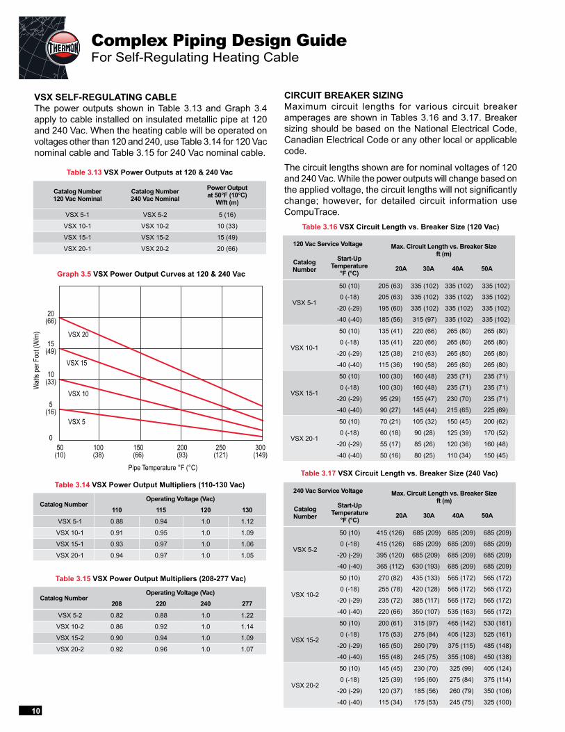
VSX SELF-REGULATING CABLE The power outputs shown in Table 3.13 and Graph 3.4 apply to cable installed on insulated metallic pipe at 120 and 240 Vac. When the heating cable will be operated on voltages other than 120 and 240, use Table 3.14 for 120 Vac nominal cable and Table 3.15 for 240 Vac nominal cable.
Table 3.13 VSX Power Outputs at 120 & 240 Vac
Graph 3.5 VSX Power Output Curves at 120 & 240 Vac
Watt
s per
Foo
t (W
/m)
10(33)
15(49)
Pipe Temperature °F (°C)
VSX 20
VSX 5
0
5(16)
20(66)
VSX 10
VSX 15
Table 3.14 VSX Power Output Multipliers (110-130 Vac)
Table 3.15 VSX Power Output Multipliers (208-277 Vac)
CIRCUIT BREAKER SIZING Maximum circuit lengths for various circuit breaker amperages are shown in Tables 3.16 and 3.17. Breaker sizing should be based on the National Electrical Code, Canadian Electrical Code or any other local or applicable code.
The circuit lengths shown are for nominal voltages of 120 and 240 Vac. While the power outputs will change based on the applied voltage, the circuit lengths will not significantly change; however, for detailed circuit information use CompuTrace.
Table 3.16 VSX Circuit Length vs. Breaker Size (120 Vac)
Table 3.17 VSX Circuit Length vs. Breaker Size (240 Vac)
Catalog Number 120 Vac Nominal
Catalog Number 240 Vac Nominal
Power Output at 50°F (10°C)
W/ft (m)
VSX 5-1 VSX 5-2 5 (16)
VSX 10-1 VSX 10-2 10 (33)
VSX 15-1 VSX 15-2 15 (49)
VSX 20-1 VSX 20-2 20 (66)
Catalog NumberOperating Voltage (Vac)
110 115 120 130
VSX 5-1 0.88 0.94 1.0 1.12
VSX 10-1 0.91 0.95 1.0 1.09
VSX 15-1 0.93 0.97 1.0 1.06
VSX 20-1 0.94 0.97 1.0 1.05
Catalog NumberOperating Voltage (Vac)
208 220 240 277
VSX 5-2 0.82 0.88 1.0 1.22
VSX 10-2 0.86 0.92 1.0 1.14
VSX 15-2 0.90 0.94 1.0 1.09
VSX 20-2 0.92 0.96 1.0 1.07
120 Vac Service Voltage Max. Circuit Length vs. Breaker Sizeft (m)
20A 30A 40A 50A Catalog Number
Start-Up Temperature
°F (°C)
VSX 5-1
50 (10) 205 (63) 335 (102) 335 (102) 335 (102)
0 (-18) 205 (63) 335 (102) 335 (102) 335 (102)
-20 (-29) 195 (60) 335 (102) 335 (102) 335 (102)
-40 (-40) 185 (56) 315 (97) 335 (102) 335 (102)
VSX 10-1
50 (10) 135 (41) 220 (66) 265 (80) 265 (80)
0 (-18) 135 (41) 220 (66) 265 (80) 265 (80)
-20 (-29) 125 (38) 210 (63) 265 (80) 265 (80)
-40 (-40) 115 (36) 190 (58) 265 (80) 265 (80)
VSX 15-1
50 (10) 100 (30) 160 (48) 235 (71) 235 (71)
0 (-18) 100 (30) 160 (48) 235 (71) 235 (71)
-20 (-29) 95 (29) 155 (47) 230 (70) 235 (71)
-40 (-40) 90 (27) 145 (44) 215 (65) 225 (69)
VSX 20-1
50 (10) 70 (21) 105 (32) 150 (45) 200 (62)
0 (-18) 60 (18) 90 (28) 125 (39) 170 (52)
-20 (-29) 55 (17) 85 (26) 120 (36) 160 (48)
-40 (-40) 50 (16) 80 (25) 110 (34) 150 (45)
240 Vac Service Voltage Max. Circuit Length vs. Breaker Sizeft (m)
20A 30A 40A 50A Catalog Number
Start-Up Temperature
°F (°C)
VSX 5-2
50 (10) 415 (126) 685 (209) 685 (209) 685 (209)
0 (-18) 415 (126) 685 (209) 685 (209) 685 (209)
-20 (-29) 395 (120) 685 (209) 685 (209) 685 (209)
-40 (-40) 365 (112) 630 (193) 685 (209) 685 (209)
VSX 10-2
50 (10) 270 (82) 435 (133) 565 (172) 565 (172)
0 (-18) 255 (78) 420 (128) 565 (172) 565 (172)
-20 (-29) 235 (72) 385 (117) 565 (172) 565 (172)
-40 (-40) 220 (66) 350 (107) 535 (163) 565 (172)
VSX 15-2
50 (10) 200 (61) 315 (97) 465 (142) 530 (161)
0 (-18) 175 (53) 275 (84) 405 (123) 525 (161)
-20 (-29) 165 (50) 260 (79) 375 (115) 485 (148)
-40 (-40) 155 (48) 245 (75) 355 (108) 450 (138)
VSX 20-2
50 (10) 145 (45) 230 (70) 325 (99) 405 (124)
0 (-18) 125 (39) 195 (60) 275 (84) 375 (114)
-20 (-29) 120 (37) 185 (56) 260 (79) 350 (106)
-40 (-40) 115 (34) 175 (53) 245 (75) 325 (100)
50(10)
100(38)
150(66)
200(93)
250(121)
300(149)
10
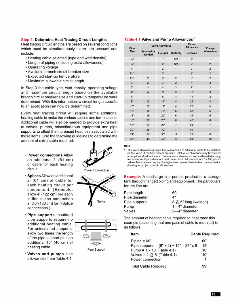
Step 4: Determine Heat Tracing Circuit LengthsHeat tracing circuit lengths are based on several conditions which must be simultaneously taken into account and include: • Heating cable selected (type and watt density) • Length of piping (including extra allowances) • Operating voltage • Available branch circuit breaker size • Expected start-up temperature • Maximum allowable circuit length
In Step 3 the cable type, watt density, operating voltage and maximum circuit length based on the available branch circuit breaker size and start-up temperature were determined. With this information, a circuit length specific to an application can now be determined.
Every heat tracing circuit will require some additional heating cable to make the various splices and terminations. Additional cable will also be needed to provide extra heat at valves, pumps, miscellaneous equipment and pipe supports to offset the increased heat loss associated with these items. Use the following guidelines to determine the amount of extra cable required:
Example: A discharge line pumps product to a storage tank through flanged piping and equipment. The particulars for the line are:
Pipe length 60' Pipe diameter 4" Pipe supports 8 @ 6" long (welded) Pump 1—4" diameter Valves 2—4" diameter
The amount of heating cable required to heat trace this example (assuming that one pass of cable is required) is as follows:
Item Cable Required
Piping = 60' 60' Pipe supports = (6" x 2) + 15" = 27" x 8 18' Pump = 1 x 10' (Table 4.1) 10' Valves = 2 @ 5' (Table 4.1) 10' Power connection 1'
Total Cable Required 99'
Table 4.1 Valve and Pump Allowances 1
• Power connections Allow an additional 2' (61 cm) of cable for each heating circuit.
• Splices Allow an additional 2' (61 cm) of cable for each heating circuit per component. (Example, allow 4' (122 cm) per each in-line splice connection and 6' (183 cm) for T-Splice connections.)
• Pipe supports Insulated pipe supports require no additional heating cable. For uninsulated supports, allow two times the length of the pipe support plus an additional 15" (40 cm) of heating cable.
• Valves and pumps Use allowances from Table 4.1.
Power Connection
Splice
Pipe Support
Pipe Size
Valve Allowance Pump Allowance Flange
AllowanceScrewed or Welded Flanged Butterfly Screwed
½" 1' 1' N/A 1' 1'
¾" 1' 2' N/A 2' 2'
1" 1' 2' 1' 2' 2'
1¼" 1' 2' 1' 2' 2'
1½" 2' 3' 2' 3' 2'
2" 2' 3' 2' 4' 2'
3" 3' 4' 3' 7' 2'
4" 4' 5' 3' 10' 3'
6" 7' 8' 4' 16' 3'
8" 10' 11' 4' 22' 4'
10" 13' 14' 4' 28' 4'
12" 15' 17' 5' 33' 5'
14" 18' 20' 6' 39' 6'
16" 22' 23' 6' 46' 6'
18" 26' 27' 7' 54' 7'
20" 29' 30' 7' 60' 7'
24" 34' 36' 8 72' 8'
30" 40' 42' 10' 84' 10'
Note1. The valve allowance given is the total amount of additional cable to be installed
on the valve. If multiple tracers are used, total valve allowance may be divided among the individual tracers. The total valve allowance may be alternated among tracers for multiple valves in a heat trace circuit. Allowances are for 150 pound valves. More cable is required for higher rated valves. Refer to heat trace isometric drawing for project specific allowances.
11
Complex Piping Design GuideFor Self-Regulating Heating Cable
Step 5: Choose Options/Accessories
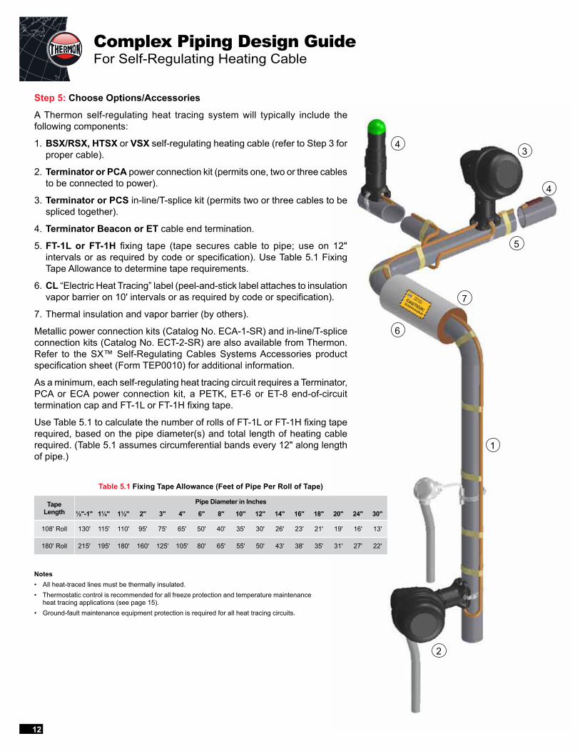
A Thermon self-regulating heat tracing system will typically include the following components:
1. BSX/RSX, HTSX or VSX self-regulating heating cable (refer to Step 3 for proper cable).
2. Terminator or PCA power connection kit (permits one, two or three cables to be connected to power).
3. Terminator or PCS in-line/T-splice kit (permits two or three cables to be spliced together).
4. Terminator Beacon or ET cable end termination.
5. FT-1L or FT-1H fixing tape (tape secures cable to pipe; use on 12" intervals or as required by code or specification). Use Table 5.1 Fixing Tape Allowance to determine tape requirements.
6. CL “Electric Heat Tracing” label (peel-and-stick label attaches to insulation vapor barrier on 10' intervals or as required by code or specification).
7. Thermal insulation and vapor barrier (by others).
Metallic power connection kits (Catalog No. ECA-1-SR) and in-line/T-splice connection kits (Catalog No. ECT-2-SR) are also available from Thermon. Refer to the SX™ Self-Regulating Cables Systems Accessories product specification sheet (Form TEP0010) for additional information.
As a minimum, each self-regulating heat tracing circuit requires a Terminator, PCA or ECA power connection kit, a PETK, ET-6 or ET-8 end-of-circuit termination cap and FT-1L or FT-1H fixing tape.
Use Table 5.1 to calculate the number of rolls of FT-1L or FT-1H fixing tape required, based on the pipe diameter(s) and total length of heating cable required. (Table 5.1 assumes circumferential bands every 12" along length of pipe.)
Table 5.1 Fixing Tape Allowance (Feet of Pipe Per Roll of Tape)
Notes• All heat-traced lines must be thermally insulated.• Thermostatic control is recommended for all freeze protection and temperature maintenance
heat tracing applications (see page 15).• Ground-fault maintenance equipment protection is required for all heat tracing circuits.
TapeLength
Pipe Diameter in Inches
½"-1" 1¼" 1½" 2" 3" 4" 6" 8" 10" 12" 14" 16" 18" 20" 24" 30"
108' Roll 130' 115' 110' 95' 75' 65' 50' 40' 35' 30' 26' 23' 21' 19' 16' 13'
180' Roll 215' 195' 180' 160' 125' 105' 80' 65' 55' 50' 43' 38' 35' 31' 27' 22'
5
43
7
1
2
6
4
12
DESIGN TIPSTo ensure a properly operating heat tracing system and avoid the common mistakes made by first-time users, the following tips have been compiled:
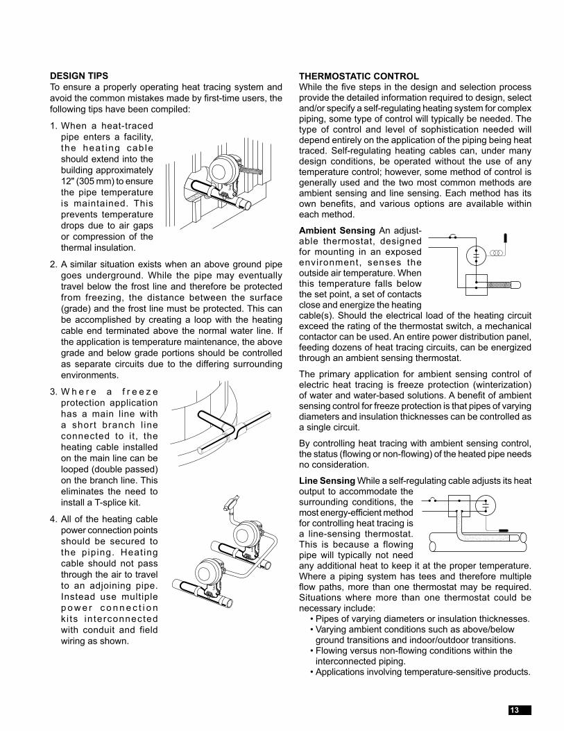
1. When a heat-traced pipe enters a facility, the heat ing cab le should extend into the building approximately 12" (305 mm) to ensure the pipe temperature is maintained. This prevents temperature drops due to air gaps or compression of the thermal insulation.
2. A similar situation exists when an above ground pipe goes underground. While the pipe may eventually travel below the frost line and therefore be protected from freezing, the distance between the surface (grade) and the frost line must be protected. This can be accomplished by creating a loop with the heating cable end terminated above the normal water line. If the application is temperature maintenance, the above grade and below grade portions should be controlled as separate circuits due to the differing surrounding environments.
3. W h e r e a f r e e z e protection application has a main line with a short branch l ine connected to it, the heating cable installed on the main line can be looped (double passed) on the branch line. This eliminates the need to install a T-splice kit.
4. All of the heating cable power connection points should be secured to the piping. Heat ing cable should not pass through the air to travel to an adjoining pipe. Instead use multiple p o w e r c o n n e c t i o n k i ts in terconnected with conduit and field wiring as shown.
THERMOSTATIC CONTROLWhile the five steps in the design and selection process provide the detailed information required to design, select and/or specify a self-regulating heating system for complex piping, some type of control will typically be needed. The type of control and level of sophistication needed will depend entirely on the application of the piping being heat traced. Self-regulating heating cables can, under many design conditions, be operated without the use of any temperature control; however, some method of control is generally used and the two most common methods are ambient sensing and line sensing. Each method has its own benefits, and various options are available within each method.
Ambient Sensing An adjust-able thermostat, designed for mounting in an exposed environment, senses the outside air temperature. When this temperature falls below the set point, a set of contacts close and energize the heating cable(s). Should the electrical load of the heating circuit exceed the rating of the thermostat switch, a mechanical contactor can be used. An entire power distribution panel, feeding dozens of heat tracing circuits, can be energized through an ambient sensing thermostat.
The primary application for ambient sensing control of electric heat tracing is freeze protection (winterization) of water and water-based solutions. A benefit of ambient sensing control for freeze protection is that pipes of varying diameters and insulation thicknesses can be controlled as a single circuit.
By controlling heat tracing with ambient sensing control, the status (flowing or non-flowing) of the heated pipe needs no consideration.
Line Sensing While a self-regulating cable adjusts its heat output to accommodate the surrounding conditions, the most energy-efficient method for controlling heat tracing is a line-sensing thermostat. This is because a flowing pipe will typically not need any additional heat to keep it at the proper temperature. Where a piping system has tees and therefore multiple flow paths, more than one thermostat may be required. Situations where more than one thermostat could be necessary include: • Pipes of varying diameters or insulation thicknesses. • Varying ambient conditions such as above/below
ground transitions and indoor/outdoor transitions. • Flowing versus non-flowing conditions within the
interconnected piping. • Applications involving temperature-sensitive products.
13
Use the following worksheet to apply the information to a specific application.
Step 1: Establish Design ParametersCollect relevant project data:
PIPING INFORMATION Circuit No. Diameter Length Material 1
Electrical Information
Operating voltage
Circuit breaker capacity
Electrical area classification
Insulation Information
Type
Thickness
Oversized (to accommodate cable) Yes No
Temperature Information
Low ambient
Start-up temperature
Maintain temperature
High temperature exposure
Equipment Information
Circuit No. Qty. Dia. Description 2 Type 3
Step 2: Determine Heat Losses
USING TABLES 2.2 THROUGH 2.7Select table based on temperature differential (∆T) between low ambient and maintain temperature.
Circuit No. Table/∆T Used Heat Loss
Notes1. If using nonmetallic piping, contact Thermon.2. Type of equipment; i.e. valve, pump, strainer, etc.3. Flanged, welded or screwed.
Step 3: Select the Proper Thermon Heating CableBased on: • Maintain temperature • Exposure temperature • Required heat output at maintain temperature
Circuit No. Cable Selected Watt Density
APPLY INSULATION CORRECTION FACTOR FROM TABLE 2.1 Circuit No. Heat Loss Multiplier Corrected Heat Loss
x =
x =
x =
x =
Design WorkSheet
14
Step 4: Determine Heat Tracing Circuit LengthsProvide sufficient cable for:
Pipe length
Supports (2 x length + 15") x number of supports
EQUIPMENTValves
Pumps
Other
TERMINATIONS/SPLICESPower connection (1' per circuit)
In-line splices (3' per splice x number of splices)
T-splices (3' per splice x number of splices)
Total Cable Length
Verify that the total cable length per circuit does not exceed the limit for the cable type and watt density chosen based on circuit breaker size and start-up temperature.
Step 5: Choose Options/Accessories
POWER CONNECTION/SPLICE KITSTerminator™ nonmetallic kits are approved for ordinary and Division 2 hazardous locations. The kits have a maximum service temperature rating of 482°F (250°C). TracePlus™ nonmetallic kits are approved for ordinary and Division 2 hazardous locations. The kits have a maximum service temperature rating of 400°F (204°C).
Terminator DP, TracePlus PCA-H or TracePlus PCA-V is designed for connecting up to three heating cables to power and may also be used as an in-line or T-splice connection kit.
Terminator DS/DE, TracePlus PCS-H or TracePlus PCA-V is designed to fabricate accessible outside-the-insulation splices.
Terminator DE-B, DL, TracePlus VIL-6H or TracePlus VIL-6V is designed to provide visual indication of an energized heating circuit.
Design WorkSheet (cont’d)
Circuit Number
Kit Type
Power Conn. Splice End Term.
Totals
Thermon metallic accessories are approved for ordinary and Division 2 hazardous locations. The kits utilize epoxy-coated aluminum junction boxes and expediters.
ECA-1-SR is designed for connecting one or two heating cables to power or for splicing two cables together.
ECT-2-SR is designed for connecting three heating cables to power or for splicing three cables together.
VIL-4C-SR is designed to provide visual indication of an energized heating circuit.
PETK Kits are designed to properly terminate both ends of an SX heat tracing circuit.
ET-6C and ET-8C end termination kits are designed to properly terminate the end (away from power) of an SX heat tracing circuit.
Power connection, splice and end termination kits:
Circuit number
15
The following sample specification is intended to provide the user with a tool to ensure that the proper guidelines are in place for specifying the use of self-regulating heating cable on a complex piping system. This specification, plus others, are available from Thermon in both printed and electronic formats.
Part 1 GeneralDesign, furnish and install a complete system of heaters and components approved by Factory Mutual Research (FM), Underwriters Laboratories Inc. (UL) and/or the Canadian Standards Association (CSA) specifically for pipe heat tracing. The heat tracing system shall conform to the latest edition of the applicable requirements of the following codes and standards: • National Electrical Code (NEC/NFPA 70) • National Fire Protection Association (NFPA) • Occupational Safety and Health Act (OSHA) • National Electrical Manufacturers Association
(NEMA) • American National Standards Institute (ANSI) • Institute of Electrical and Electronic Engineers
(IEEE) • All applicable local codes and standards
Part 2 Design1. The equipment, materials and installation shall be suited
for the electrical classification of the area involved. Area classification drawings shall be available for identifying the boundaries of the areas.
2. A minimum safety factor of 10% shall be used to determine heat loss.
3. Heat loss calculations shall consider that the thermal insulation may be oversized to allow space for the heating cable(s).
4. Heater cable lengths for piping shall include cable on all in-line components including, but not limited to, flanges, pumps, valves, pipe supports/hangers, vents/drains and instruments.
Part 3 ProductsHeating cables used on this project shall be self-regulating in nature and vary their output in response to temperature variations along the length of a traced pipe. The heat tracing contractor shall be responsible for selecting the type of heating cable to be used for a given application based on the design and operating environment requirements. The following self-regulating heating cables are approved for use on this project.
LOW TEMPERATURE1. Self-regulating heating cable design shall be capable of
maintaining process temperatures up to 150°F (65°C) and continuous exposure to temperatures of 185°F (85°C) while de-energized.
2. Cable must be capable of being cut to a desired length to suit the installation conditions and must form a continuous heating circuit.
3. The heating cable shall consist of two parallel 16 AWG nickel-plated copper bus wires embedded in a semiconductive polymer core that forms a continuous matrix heating element. A polyethylene dielectric insulating jacket is extruded over the heating element core.
4. The basic cable shall be covered by means of a metallic braid of tinned copper. The braid shall provide a nominal coverage of 70%.
5. Cables braided with tinned copper shall be further covered with corrosion resistant overjacket of polyethylene (for exposure to aqueous inorganic chemicals) or fluoropolymer (for exposure to organic chemicals or corrosives).
6. Long-term stability shall be established by the service life performance test per IEEE Std 515.
MEDIUM TEMPERATURE1. Self-regulating heating cable design shall be capable of
maintaining process temperatures up to 302°F (150°C) and intermittent exposure to temperatures of 482°F (250°C) (power on or off) and 400°F (204°C) continuous pipeline exposure temperature while de-energized.
2. Cable must be capable of being cut to a desired length to suit the installation conditions and must form a continuous heating circuit.
3. The heating cable shall consist of two parallel 16 AWG nickel-plated copper bus wires embedded in a semiconductive polymer core that forms a continuous matrix heating element. A fluoropolymer dielectric insulating jacket is extruded over the heating element core.
4. The basic cable shall be covered by means of a plated copper braid. The braid shall provide a nominal coverage of 70%.
5. Cables braided with plated copper shall be further covered with corrosion resistant overjacket of fluoropolymer.
6. Long-term stability shall be established by the service life performance test per IEEE Std 515.
General Specification
16
HIGH TEMPERATURE1. Self-regulating heating cable design shall be capable of
maintaining process temperatures up to 300°F (149°C) and intermittent pipeline exposure temperatures of 450°F (232°C) while energized and 400°F (204°C) continuous pipeline exposure temperatures while de-energized.
2. Cable must be capable of being cut to a desired length to suit the installation conditions and must form a continuous heating circuit.
3. The heating cable shall consist of two parallel 14 AWG nickel-plated copper bus wires embedded in a semiconductive polymer core that forms a continuous matrix heating element. A high temperature fluoropolymer dielectric insulating jacket is extruded over the heating element core.
4. The basic cable shall be covered by means of a metallic braid of nickel-plated copper. The braid shall provide a nominal coverage of 70%.
5. Cables braided with tinned copper shall be further covered with corrosion resistant overjacket of fluoropolymer.
6. Long-term stability shall be established by the service life performance test per IEEE Std 515.
Part 4 Installation1. Refer to the manufacturer’s installation instructions
and design guide for proper installation and layout methods. Deviations from these instructions could result in performance characteristics different than intended.
2. All installations and terminations must conform to the NEC and any other applicable national or local code requirements.
3. All heat tracing circuits shall be equipped with ground-fault equipment protection in accordance with applicable codes and standards.
4. Heating cable shall preferably be installed on pipes in a single pass without spiral wrapping. Where the heat loss of the pipe exceeds the output of the cable, an additional pass or passes shall be used unless approval has been granted by owner’s engineer to permit spiral wrapping.
5. Heating cable shall be attached to pipes on maximum one-foot (30 cm) intervals.
6. Heating cable shall be installed such that all in-line devices and equipment may be easily removed and reinstalled without cutting the heating cable.
7. Heating cable shall be installed on the lower quadrant of horizontal pipe whenever possible to avoid mechanical damage. Cable shall be located on the outside radius of all 45° and 90° pipe elbows.
Part 5 Testing1. Heating cable shall be tested with a megohmeter
(megger) between the heating cable bus wires and the heating cable metallic braid. While a 2,500 Vdc megger test is recommended, the minimum acceptable level for testing is 500 Vdc. This test should be performed a minimum of three times:a. Prior to installation while the cable is still on reel(s).b. After installation of heating cable and completion of
circuit fabrication kits (including any splice kits) but prior to installation of thermal insulation.
c. After installation of thermal insulation but prior to connection to power.
2. The minimum acceptable level for the megger readings is 20 megohms, regardless of the circuit length.
3. Results of the megger readings should be recorded and submitted to the construction manager.
17

Corporate Headquarters:100 Thermon Dr • PO Box 609 San Marcos, TX 78667-0609 • Phone: 512-396-5801 • 1-800-820-4328 For the Thermon office nearest you visit us at . . . www.thermon.com
© Thermon, Inc. • Printed in U.S.A. • Information subject to change.Form TEP0013-0317
OFFICES WORLDWIDEUNITED STATES CANADA MEXICO NETHERLANDS UNITED KINGDOM FRANCE SPAIN SOUTH KOREA RUSSIA INDIA AUSTRALIA MALAYSIA GERMANYJAPAN CHINA BAHRAIN BRAZIL SOUTH AFRICA