Embed Size (px)
Citation preview
IEEE TRANSACTIONS O N COMMUNICATION TECHNOLOGY, VOL. COM-19, NO. 5, OCTOBER 1971 835
under laboratory conditions is repeatably within a few tenths of a decibel of predictions based on theory and simulation. On real channels, the fragmentary results available to date regularly show the same order of gain, albeit without the same sort of repeatability. These re- sults confirm that a sequential decoder of modest com- plexity can provide of the order of 5-dB effective power gain at data rates to 5 Mbit/s and that above threshold very low error probabilities can be achieved.
ACKNOWLEDGMENT
We are grateful to the personnel of the U. S. Army Satellite Communication Agency who supported this work: R.’M. Langelier, without whose initial enthusiasm the work would never have begun; D. L. LaBanca, who provided continuity of support; and T. F. Page, R.. J. Stark, R. C. Gibson, and G. R.. Ash, who were by turns responsible for the progress of the program. The data supplied by these gentlemen and by D. Quagliato of the U. S. Army Electronics Command are also grate- fully acknowledged. We also wish to cite s. H. Loui of Codex for his indefatigable assistance in the con- struction of the prototype.
REFERENCES [11 K. L. Jordan, Jr., “The performance of sequential decoding
in conjunction with efficient modulation,” IEEE Trans. Commun. Technol., vol. COM-14, June 1966, pp. 283-297.
c21
131
141
151
I. L. Lebow and P. G. McHugh, “A sequential decoding technique and its realization in the Lincoln experimental terminal,” IEEE Trans. ,Commun. Technol., vol. COM-15,
I. M. Jacobs, Sequential decoding for efficient communi- cation from deep space,’’ IEEE Trans. Commun. Technol.,
modulation of phase shift keying,” IEEE Trans. Commun. C. R. Cahn, “Binary decoding extended to nonbinary de-
G. D. Forney, Jr., and R. M. Langelier, liA high-speed Technol., vol. COM-17, Oct. 1969, pp. 583-588.
sequential decoder for satellite communications,” Conf. Rec., 1969 IEEE I n t . Conj. Communications, Boulder, Colo., June
Aug. 1967, pp. 477-491’.
V O ~ . COM-15, Aug. 1967, pp. 492-501.
1968. OD. 39/9-17. [61 G. D: -Forney, Jr., “Use of a se uential decoder to analyze
convolutlonal code structure,” I j E E Trans. Inform. Theory (Comrresp.), vol, IT-16, Nov. 1970, pp. 793-795.
[71 R. ,G. Gallager, Information Theory and Reliable Con~muni-
181 D. Quagliato, “Advanced coding technlques for satellite catzo?~. New York: Wiley, 1968, pp. 263-273.
communications,” U. S. Army Elect.ron. Command, Ft. Monmouth, N. J., CADPL Rep. 167. Sept. 1970.
G. David Forney, Jr. (S’59-M’61), for a photograph and biography please see page 781 of this issue.
Edward K. Bower was born in Columbia, Mo., on July 8, 1943. He attended the Uni- versity of Missouri, Columbia, from which he received the B.S., M.S., and Ph.D. degrees in electrical engineering in 1964, 1965, and 1968, respectively. While a graduate student, he held an NSF Cooperative %ollowship and a NASA traineeship. His area of specializa- tion was coding theory.
Since graduation, he has been employed by the Codex Corporation, Newton, Mass. As a
Senior Member of the Technical Staff, he has been active in the development of coding and modulation devices.
Viterbi Decoding for Satellite and Space Communication
Abstract-Convolutional coding and Viterbi decoding, along with binary phase-shift keyed modulation, is presented as an efficient system for reliable communication on power limited satellite and space channels. Performance results, obtained theoretically and through computer simulation, are given for optimum short constraint length codes for a range of code constraint lengths and code rates. System efficiency is compared for hard receiver quantiza- tion and 4 and 8 level soft quantization. The effects on performance of varying of certain parameters relevant to decoder complexity and cost is examined. Quantitative performance degradation due to imperfect carrier phase coherence is evaluated and compared to that of an uncoded system. As an example of decoder performance versus complexity, a recently implemented Z-Mbit/s constraint length 7 Viterbi decoder is discussed. Finally a comparison is
the JEEE Communication Technology Group for publication Paper approved by the Communication Theory Committee of
without oral presentation. This work was supported in part by NASA Ames Research Center under Contract NAS2-6024. Manu- script received June 10, 1971.
The authors are with the Linkabit Corporation, San Diego, Calif.
made between Viterbi and sequential decoding in terms of suit- ability to various system requirements.
I. INTRODUCTION
HE SATELLITE and space communication chan- nels are likely candidates for the cost-effective use of coding to improve communication efficiency. The
primary additive disturbance on these channels can usually be accurately modeled by Gaussian noise which is “white” enough to be essentially independent from one bit time interval to the next, and, particularly on the space channel but also in many instances on satellite channels, sufficient bandwidth is available to permit moderate bandwidth expansion. Two effective decoding algorithms for independent noise (memoryless) channels have been developed and refined, namely sequential and Viterbi decoding of convolutional codes. These theoretical accomplishments, combined with real communication
836
needs and the availability of low-cost complex digital integrated circuits, make possible practical and powerful high-speed decoders for satellite and space communica- tion.
Communication from a distant and isolated object in space to a ground-based station presents certain system problems which are not nearly as critical in earth-based communication systems. The most obvious among these is the high cost of space-platform power. It is desirable to design a system which is as efficient as practical in order to minimize the spacecraft weight necessary to generate power.
The nlodulated signal power a t a ground station re- ceiver front end P depends upon the transmitted power, the transmitting and receiving antenna gains, and prop- agation path losses. Primarily due to thermal activity at the receiver front end, wideband noise is added to the received signal, resulting in a received signal power- to-noise ratio (PIN , , ) , where N,, is the single-sided noise spectral density. The noise is usually accurately modeled as being both white and Gaussian. Other perturbations caused by uncertainty in carrier phase at the demodulator and inaccuracies in receiver AGC are treated in Sections IV and V.
The efficiency of a communication system is usefully measured by the received energy per bit to noise ratio (E,/N,,) required to achieve a specified system bit error rate. The E b / N o is expressable in terms of the modulat- ing signal power by the relationship
E, P 1 Nn Nn R - - - -.-
where R is the information rate Alternatively, (1) can be written as
The payoff for using modulation
(1)
in bits per second.
(2)
and/or coding tech- niques which reduce the Eb/lVo required for a given bit error probability is an increase in allowable data rate and/or a decrease in necessary received PJN,,.
As a point of reference, i t is traditional to compare the efficiency of modulation-coding schemes with that of a hypothetical system operating a t channel capacity. Channel capacity for an infinite bandwidth white Gaus- sian noise channel with average power P is [ l]
c- = -2 bit/s.
From (1), when R = C,,
Thus, the lower bound on achievable E b / N o is about
Without coding, required E b / N o can be minimized by selecting an efficient modulation technique. For example,
-1.6 dB.
IEEE TRANSACTIONS ON COMMUNICATION TECHNOLOGY, OCTOBER 1971
180” binary phase-shift keying (BPSK) is more efficient than binary frequency shift keying (BFSK). For a de- sired bit error rate of an Eb, /NO of 9.6 dB is re- quired using BPSK (antipodal) modulation, whereas, 12.6 dB is required with BFSK (orthogonal) modulation. Quadraphase-shift keying (QPSK) is often used t o con- serve bandwith. Under the assumption of perfect phase coherence, QPSK has the same performance as BPSK.
I n designing a communication system to operate a t a specified data rate, the improvement in efficiency to be realized using coding must be weighed against the rela- tive costs. Potential alternatives include increasing the transmitted power, increasing the transmitting antenna gain, and/or the receiving antenna area, and accepting a higher proba.bility of bit error. In many applications, a minimum P, is required and thc incremental cost per decibel increase in P / N , is now greater (often much greater) than the cost of reducing the needed Eb/No through coding. Soft dccision Viterbi and hard decision sequential clecoding can provide a relatively inexpensive 4-6-dB improvement in required E b / N o ( a t a bit error rate), even a t multimegahit data rates. Sequential decoding is extensively discussed in [ 5 ] . I n Section VII, we compare these techniques. Sections I1 and 111 examine various aspects of Viterbi decoding and present curves permitting system tradeoffs. I n Section VI, a particular implementation of a Viterbi decoder is discussed to pro- vide one benchmark for cost-complexity discussions.
In the discussion that follows, we assume that the channel is power limited rather than bandwidth limited. This assumption is realistic for many present day and future systems; however, the trend, especially in satel- lite repeaters, is to larger P;/N,, without a proportional increase in available bandwidth. For this reason, we will limit consideration to codes which involve a “band- width expansion” of 3 or less; that is, we assume that from 1 to 3 binary symbols can be transmitted over the channel for each bit of information communicated witllout appreciable intersymbol interference.
11. SYSTEM
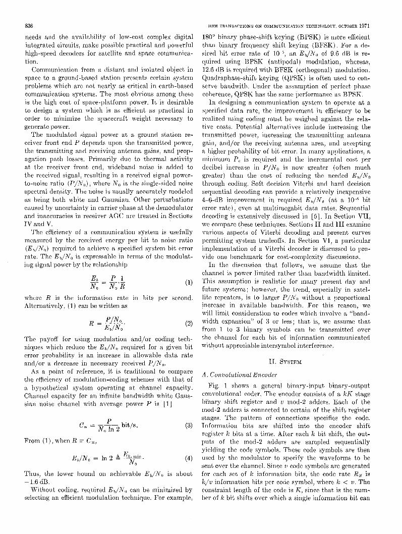
A . Convolutional Encoder Fig. 1 shows a general binary-input binary-output
convolutional coder. The encoder consists of a k K stage binary shift register and mod-2 adders. Each of the mod-2 adders is connected to certain of the shift register stages. The pattern of connections specifies the code. Information bits are shifted into the encoder shift register k bits a t a time. After each k bit shift, the out- puts of the mod-2 adders are sampled sequentially yielding the code symbols. These code symbols are then used by the modulator to specify the waveforms to be sent over the channel. Since v code symbols are generated for each set of k information bits, the code rate RN is k J v information bits per code symbol, where k < v. The constraint length of the code is K , since that is the num- ber of k bit shifts over which a single information bit can
837
is 0 or 1. The funct)ion p ( t ) is a convenient unit energy low-pass pulse waveform, f c is the carrier frequency, E, is the energy per pulse, and T , is the time between suc- cessive code symbols. E , and T , are defined by the rela- tionships
E, = RNE, = kEb/v (6)
and
T , = R N / R . (7)
There are several reasons for restricting attention to BPSIi nodulation. Three important ones are as follows.
1) I3PSK signals are convenient to generate and am- plify. Traveling wave tube amplifiers operate most effi- ciently at or near saturation. This nonlinear amplific a t‘ 1011
would degrade performance with multilevel amplitude modulated waveforms.
2) It can be shown that antipodal (BPSK) modula- tion results in little increase in required E,,/N, compared to optimum signaling when E S / N , , is low [4].
3) BP.SK modulation of quadrature carriers is equiva- lent to quadraphase (QPSK) modulation of one carrier. Thus, QPSK need not be separately trcated except for synchronization and phase error requirements.
HELLER AND JACOBS : DECODING FOR SATELLITES
I I t COMMUTATMI
BINARY CODE SYMBOLS
Fig. 1. Ratc k/?c convolutiond encodcr.
influence the encoder output. The state of the convolu- tional encoder is the contents of the first k ( K - 1) shift register stages. The cncoder statc together with the nest IC input bits uniquely specify the u output symbols.
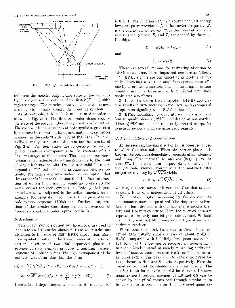
As an esample, a K = 3, k = 1, u = 2 encoder is shown in Fig. 2 (a) . The . first two coder stages specify the state of the encoder; thus, there are 4 possible states. The code words, or sequences of code symbols, generated by the encoder for various input information bit sequences is shown in the code “trellis” [a] of Fig. 2(h) . The code trellis is really just a state diagram for the encocler of Fig. 2(a). The four states are represented by circled binary numbers corresponding to the contents of the first two stages of the encoder, The lines or “branches” joining states indicate state transitions due to the input of sirlgle information bits. Dashcd and solid lines cor- respond to “1” and “0” input information bits, respec- tively. The trellis is drawn under the assumption that the encoder is in state 00 at time 0. If the first informa- tion bit were a 1, the encoder would go to state 10 and would output the code symbols 11. Code symbols gen- erated are shown adjacent to the trellis branches. As an example, the input data sequence 101 - a - generates the code symbol sequence 111000 . . Further interpreta- tions of the encoder state diagram and a discussion of [(good” convolutional codes is presented in [3].
B. h4odulation The binary symbols output by tllc encoder are used to
modulate an RF carrier sinusoid. Here we restrict our attention to the case of 180” BPSK modulation. Each code symbol results in the transmission of a pulse of carrier a t either of two 180” separated phases. A squence of code symbols produces a uniformly spaced sequence of biphnse pulscs. The signal component of the received waveform thus has the form
~ ( t ) = d2EB p ( t - ~ T J COS (2Tfct + ~ / 2 + e)
= d5E COS (zTff.t + e) - x i p ( t - ~ T J . ( 5 )
Here xi is +I deperlding on whether the ith code symbol
C. De)wodwlntion clnd &unntisatio?z
At the receiver, the signal s( t ) of ( 5 ) , is observed added to whit’e Gaussian noise. When the carrier phase e is known, the optimum demodulator consists of an integrate and dump filter matched to p(t) cos (2sf,t + e) . At time jT8 , the demodulator outputs data r i relevant to the jth code symbol. Normalizing the matched filter output by dividing byZ/N,/Z yields
ri = xi d 2 E , / N 0 + ni (8)
when nj is a zero-n1ean unit variance Gaussian random variable. Each nj is independent of all others.
To f:tcilitate digital proccssing by the decoder, the continuous r j must be quantized. The simplest quantiza- tion is a hard decision with 0 output if r j is greater than zero and 1 output otherwise. Here, the received data are represented by only one bit per code symbol. Without coding, the matched filter sampler hard quantizer is an optimum receiver.
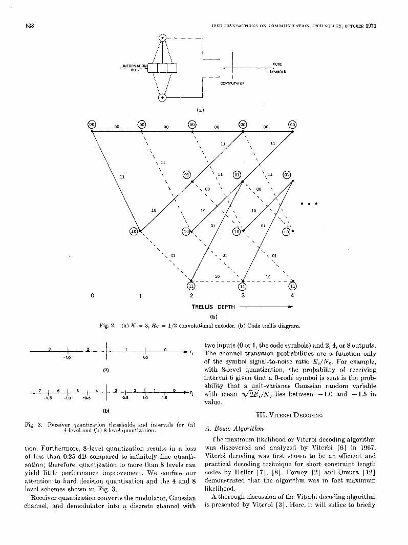
When coding is used, hard quantization of the re- ceived data usually entails a loss of about 2 dB in E,/N, compared with infinitely fine quantization [4], [5j. Much of this loss can be recouped hy quantizing ri to 4 or 8 levels instead of merely 2. Adding additional lcvcls of quantization necessitates a 2- or 3-bit represen- tation of each rj. Fig. 3(a) and (b) shows two quantiza- tion schemes with 4 and 8 levels, respectively. Here the quantization level thresholds are spaced evenly. The spacing is 1.0 for 4 levels and 0.5 for 8 levels. Uniform quantization threshold spacings of 1.0 and 0.5 can be shown by analytical means and through simulation to be very close to optimum for 4- and 8-level quantiza-
838 IEEE TRANSACTIONS ON C O M M U N I C A T I O N TECHNOLOGY, OCTOBER 1971
- I CODE
(a)
@ 00 @ 00 @ 00 @ 00 @
0 1 2 3 4
TRELLIS DEPTH * (b)
Fig. 2. (a) K = 3, RN = 1/2 convolutional encoder. (b) Code trellis diagram.
two inputs (0 or 1, the code symbols) and 2,4, or 8 outputs. * 'I The channel transition probabilities are a function only
of the symbol signal-to-noise ratio E,/N, . For example,
interval 6 given that a 0-code symbol i s sent is the prob-
3 I 2 1 I 0
-1.0 1.0
(a) with 8-level quantization, the probability of receiving
7 1 6 1 5 1 4 ability that a unit-variance Gaussian random variable
'i with mean 4 2 E 8 / N , , lies between -1.0 and - 1.5 in value.
I 3 , 2 1 1 , 0 *
I I -1.5 -1.0 -0.5 0.5 l!O 1.5
Fig. 3. Receiver quantization thresholds and intervals for (a) 4-level and (b) %level quantization.
tion. Furthermore, 8-level quantization results in a loss of less than 0.25 dB compared to infinitely fine quanti- zation; therefore, quantization to more than 8 levels can yield little performance improvement. We confine our attention to hard decision quantization and the 4 and 8 level schemes shown in Fig. 3.
Receiver quantization converts the modulator, Gaussian channel, and demodulator into a discrete channel with
111. VITERBI DECODING
A . Basic Algorithm The maximum likelihood or Viterbi decoding algorithm
was discovered and analyzed by Viterbi [6] in 1967. Viterbi decoding was first shown to be an efficient and practical decoding technique for short constraint length codes by Heller [ 71, [8] . Forney [2] and Omura [ 121 demonstrated that the algorithm was in fact maximum likelihood.
A thorough discussion of the Viterbi decoding algorithm is presented by Viterbi [3]. Here, it will suffice to briefly
HELLER A N D JACOBS: DECODING FOR SATELLITES
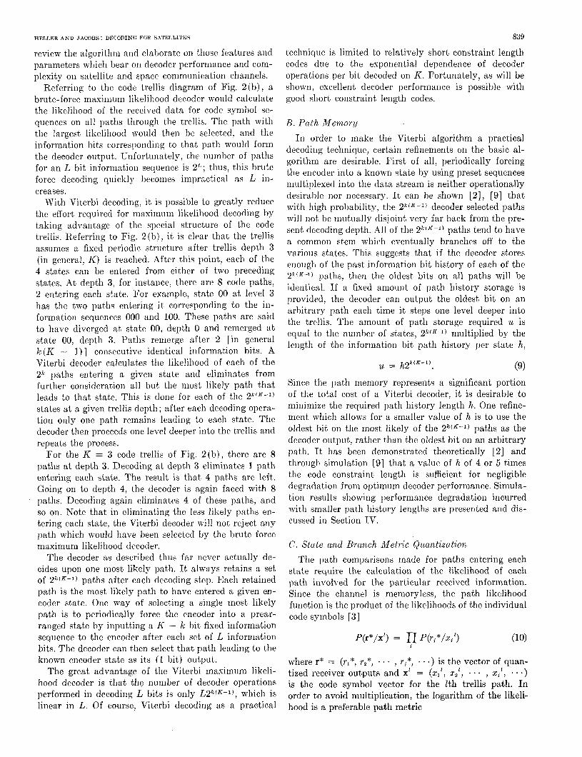
review the algorithm and elaborate on those features and parameters which bear on decoder performance and com- plexity on satellite and spacc communication channels.
Referring to the code trellis diagram of Fig. 2(b), a brute-force maximum likelihood decoder would calculate the likelihood of the received data for code symbol se- quences on all paths through the trellis. The path with the largest likelihood would then be selected, and the information bits corresponding to that path would form the decoder output. Unfortunately, the number of paths for an L bit information sequence is 2l ) ; thus, this brute force decoding quickly becomes impractical as L in- creases.
With Viterbi decoding, it is possihle to greatly reduce the effort required for masirnurn likelihood decoding by taking advantage of the special structure of the code trellis. Referring to Fig. 2 ( h ) , it is clear that the trellis assumes a fixed periodic structure after trellis depth 3 (in general, I<) is reached. After this point, each of the 4 states can be entered from either of two preceding states. At depth 3, for instance, there are 8 code paths, 2 entering each state. For example., state 00 a t level 3 has the two paths entering it corresponding to the in- formation sequences 000 and 100. These paths are said to have diverged at s ta te 00, depth 0 and remerged a t state 00, depth 3. Paths remerge after 2 [in general k ( l ( - I ) ] consecutive identical information bits. A Viterbi decoder calculates the likelihood of each of the 2k paths entering a given state and eliminates from further consideration all but the most likely path that leads to that state. This is done for each of the 27G'K-1) states at a given trellis depth; after each decoding opera- tion only one path remains leading to each state. The decoder then proceeds one level deeper into the trellis and repeats the process.
For the K = 3 code trellis of Fig. 2(b) , there are 8 paths at depth 3. Decoding at depth 3 eliminates 1 path entering each state. The result is tha t 4 paths are left. Going on to depth 4, the decoder is again faced with 8 paths. Decoding again eliminates 4 of these paths, and so on. Note that in eliminating the less likely paths en- tering each state, the Viterbi decoder will not reject any path which would have been selected by the brute force maximum likelihood decoder.
The decoder as described thus far never actually de- cides upon one most likely pat.h. It always retains a set of 2 k ' K - 1 ) paths after each decoding step. Each retained path is the most likely path to have entered a given en- coder state. One way of selecting a single most likely path is to periodically force the encoder into a prear- ranged state by inputting a I< - k bit fixed information sequence to the encoder after each set of L information bits. The decoder can then select that path leading to the known encoder state as its (1 bit) output.
The great advantage of the Viterbi maximum likeli- hood decoder is that the number of decoder operations performed in decoding L bits is only L2k(K-1) , which is linear in L. Of course, Viterbi decoding as a practical
839
technique is limited to relatively short constraint length codes due to the exponential dependence of decoder operations per bit decoded on K . Fortunately, as will be shown, excellent decoder performance is possible with good short constraint length codes.
B . Path M e m o ~ y In order to make the Viterbi algorithm a practical
decoding technique, certain refinements on the basic al- gorithm are desirable. First of all, periodically forcing the encoder into a known state by using preset sequences multiplexed into the data stream is neither operationally desirable nor necessary. It can be shown [ 2 ] , [9] that with high probability, the 2k(R-1) decoder selected paths will not be mutually disjoint very far back from the pre- sent decoding depth. All of the 2 k ( K - 1 ) paths tend to have a common stem which eventually branches off to the various states. This suggests that if the decoder stores enough of the past information bit history of each of the 2J'(K-1) paths, then the oldest bits on all paths will be identical. If a fixed amount of path history storage is provided, the decoder can output the oldest bit on an arbitrary path each time it steps one level deeper into the trellis. The amount of path storage required u is equal to the number of states, 2k(K-1) multiplied by the length of the information bit path history per state h,
= h 2 k ' K - l ) . (9) Since the path memory represents a significant portion of the total cost of a Viterbi decoder, it is desirable to minimize the required path history length h. One refine- ment which allows for a smaller value of h is to use the oldest bit on the most likely of the 2k(K-1) paths as the decoder output, rather than the oldest bit on an arbitrary path. It has been demonstrated theoretically [2] and through simulation 191 that a value of h of 4 or 5 times the code constraint length is sufficient for negligible degradation from optimum decoder performance. Simula- tion results showing performance degradation incurred with smaller path history lengths are presented and dis- cussed in Section IV.
C. State and Branch Metric Quantization The path comparisons made for paths entering each
state require the calculation of the likelihood of each path involved for the particular received information. Since the channel is memoryless, the path likelihood function is the product of the likelihoods of the individual code symbols [3]
P(r*/x') = p(r,*/xi') 1
where r* = (r1*, r2*, . . . , ri*, . .) is the vector of quan- tized receiver outputs and X' = (x1', x2', * . , xi1, * . e )
is the code symbol vector for the lth trellis path. In order to avoid multiplication, the logarithm of the likeli- hood is a preferable path metric
840
M , = log p(r*/x')
= x log p(r ,*/z iz) A x miz (1 1) i 1
where M 2 is the metric of the lth path and miz is the metric of the jth code symbol on the Zth path. With this type of additive metric, when a path is extended by one branch, the metric of the new path is the sum of the new branch symbol metrics and the old path metric. To facili- tate this calculation, the path metric for the best path leading to each state must be stored by the decoder as a state metric. This is an addition to the path information bit history storage required.
Viterbi decoder operation can then be summarized as follows, taking the K = 3 case of Fig. 2 as an example.
1) The metric for the 2 paths entering state 00 are calculated by adding the previous state metrics of states 00 and 01 to the branch metrics of the upper and lower branches entering state 00, respectively.
2) The largest of the two new path nletrics is stored as the new state metric for state 00. The new path his- tory for state 00 is the path history of the state on the winning path augmented by a 0 or 1 depending on whether state 00 or 01 was on the winning path.
3) This add-compare-select (ACS,) operation is per- formed for the paths entering each of the other 3 states.
4) The oldest bit on the path with the largest new path metric forms the decoder output.
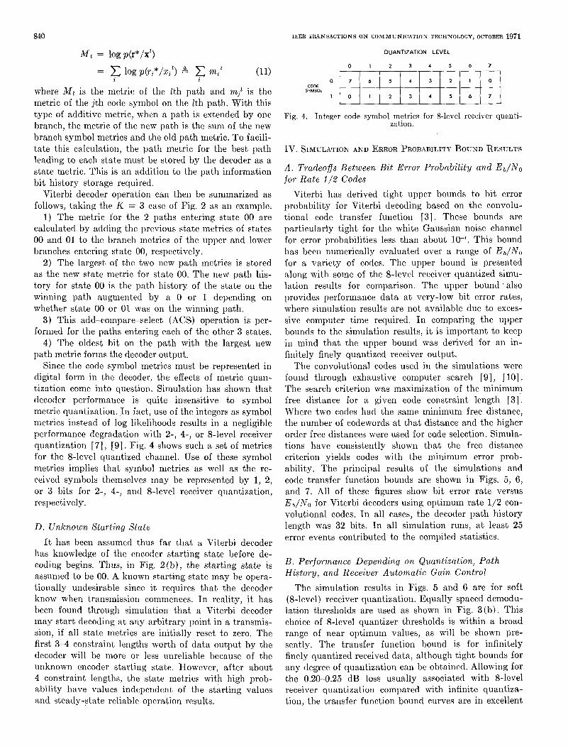
Since the code symbol metrics must be represented in digital form in the decoder, the effects of metric quan- tization come into question. Simulation has shown that decoder performance is quite insensitive to symbol metric quantization. In fact , use of the integers as symbol metrics instead of log likelihoods results in a negligible performance degradation with 2-, 4-, or 8-level receiver quantization [7], [SI. Fig. 4 shows such a set of metrics for the %level quantized channel. Use of these symbol nletrics implies that symbol metrics as well as the re- ceived symbols themselves may be represented by 1, 2, or 3 bits for 2-, 4-, and %level receiver quantization, respectively.
IEEE TRANSACTIONS ON COMMUNICATION TECHNOLOGY, OCTOBER 1971
OUANTlZATlON LEVEL
0 1 2 3 4 5 6 7
0 7 6 5 4 3 2 1 0
SYMBOL CODE
I 0 1 2 3 4 5 6 7
Fig. 4. Integer code symbol metrics for %level receiver quanti- zation.
D. Unknown Starting State It has been assumed thus far that a Viterbi decoder
has knowledge of the encoder starting state before de- coding begins. Thus, in Fig. 2 ( b ) , the starting state is assumed to be 00. A known starting state may be opera- tionally undesirable since i t requires that the decoder know when transmission commences. In reality, it has been found through simulation that a Viterbi decoder may start decoding at any arbitrary point in a transmis- sion, if all state metrics are initially reset to zero. The first 3-4 constraint lengths worth of data output by the decoder will be more or less unreliable because of the unknown encoder starting state. However, after about 4 constraint lengths, the state metrics with high prob- ability have values independent of the starting values and steady-state reliable operation results.
IV. SIMULATION AND ERROR PROBABILITY BOUND RESULTS
A . Tradeoffs Between Bit Error Probabili ty and Eb/NO for Rate 1 /2 Codes
Viterbi has derived tight upper bounds to bit error probability for Viterbi decoding based on the convolu- tional code transfer function [3 ] . These bounds are particularly tight for the white Gaussian noise channel for error probabilities less than about This bound has been numerically evaluated over a range of E b / N o for a variety of codes. The upper bound is presented along with some of the 8-level receiver quantized simu- lation results for comparison. The upper bound 'also provides performance data at very-low bit error rates, where simulation results are not available due to exces- sive computer time required. I n comparing the upper bounds to the simulation results, it is important to keep in mind that the upper bound was derived for an in- finitely finely quantized receiver output.
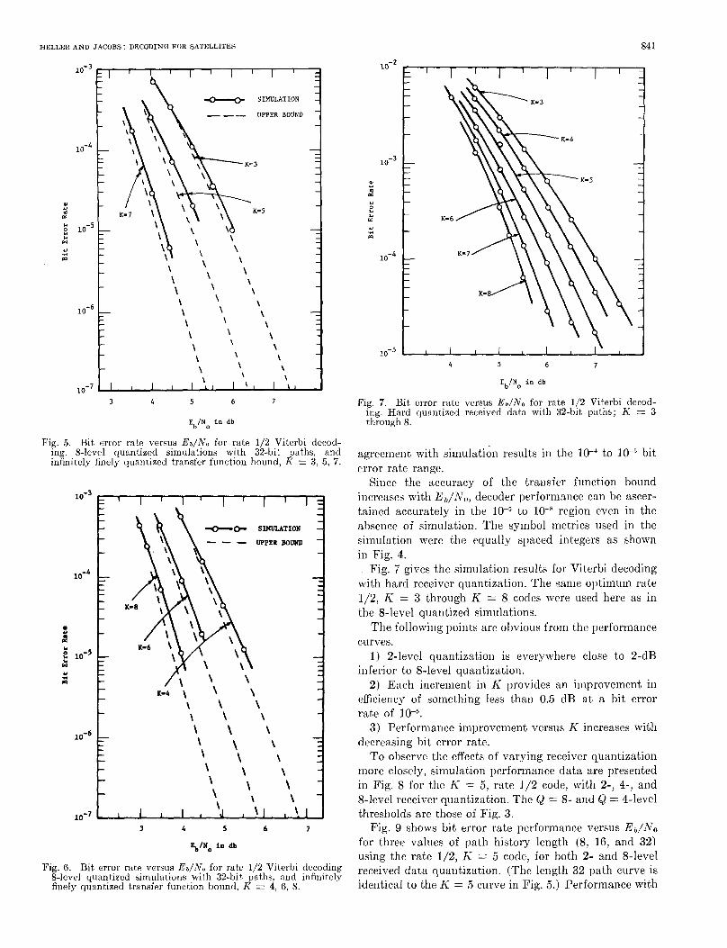
The convolutional codes used in the simulations were found through exhaustive computer search [9], [ l o ] . The search criterion was maximization of the minimum free distance for a given code constraint length [3] . Where two codes had the same minimum free distance, the number of codewords a t t ha t distance and the higher order free distances were used for code selection. Simula- tions have consistently shown that the free distance criterion yields codes with the minimum error prob- ability. The principal results of the simulations and code transfer function bounds are shown in Figs. 5, 6, and 7. All of these figures show bit error rate versus E h / N , , for Viterbi decoders using optimum rate 1/2 con- volutional codes. In all cases, the decoder path history length was 32 bits. In all simulation runs, at least 25 error events contributed to the compiled statistics.
B. Performance Depending on Quantization, Path History, and Receiver Automatic Gain Control
The simulation results in Figs. 5 and 6 are for soft (%level) receiver quantization. Equally spaced demodu- lation thresholds are used as shown in Fig. 3(b) . This choice of %level quantizer thresholds is within a broad range of near optimunl values, as will be shown pre- sently. The transfer function bound is for infinitely finely quantized received data, although tight bounds for any degree of quantization can be obtained. Allowing for the 0.20-0.25 dB loss usually associated with &level receiver quantization compared with infinite quantiza- tion, the transfer function bound curves are in excellent
HELLER AND JACOBS: DECODING FOR SATELLITES 84 I
- SIMULATION
- -- UPPER BOZRJD
Y
e: Y :: W u 4 m
\ \
3 4 5 6 7
Eb/No in db
Fig. 5. Bit error rate versus Er/No for rate 1J2 Viterbi decod- ing. 8-level qua.ntized simulations with 32-bit paths, and infinitely finely quantized transfer function bound, K = 3, 5 , 7 .
Y
3
Y r( m
10-6
10-
Fig. 6. Bit error rate versus Eb/N, , for rate 112 Viterbi decoding 8-level quantized simulations with 32-bit paths, and infinitely finely quantized transfer function bound, K = 4, 6, 8.
10-2 I I I
1 . ' l -
10-5 I I I I I I I I 1
\
4 5 6 7
EblNo in d b
Fig. 7 . Bit error rate versus Eb/Na for rate 1/2 Viterbi decod- ing. Hard quantized received data with 32-bit paths; K = 3 through 8.
agreement with simulation results in the lo-' to bit error rate range.
Since the accuracy of the transfer function bound increases with E , / N o , decoder performance can be ascer- tained accurately in the to region even in the absence of simulation. The symbol metrics used in the simulation were the equally spaced integers as shown in Fig. 4.
Fig. 7 gives the simulation results for Vitcrbi decoding with hard receiver quantization. The same optimum rate 1/2, I< = 3 through K = 8 codes were used here as in the 8-level quantized simulations.
The following points are obvious from the performance
1) 2-level quantization is everywhere close to 2-dB inferior to 8-level quantization.
2) Each increment in K provides an ilnprovement in efficiency of something less than 0.5 dB a t a bit error rate of
3) Performance improvement versus K increascs with decreasing bit error rate.
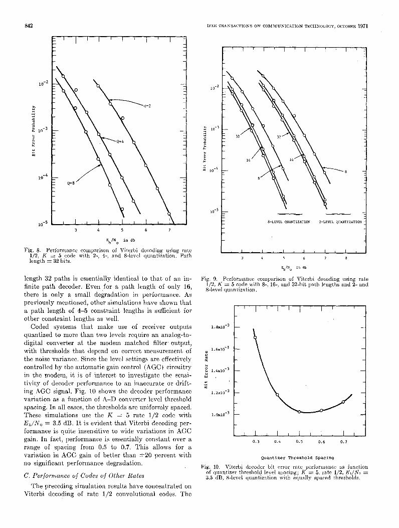
To observe the effects of varying receiver quantization more closely, simulation performance data are presented in Fig. 8 for the K = 5 , rate 1/2 code, with 2-, 4-, and 8-level receiver quantization. The Q = 8- and Q = 4-level thresholds are those of Fig. 3.
Fig. 9 shows bit error rate pcrformance versus E0/NO for three values of path history length (8, 16, and 32) using the rate 1/2, K = 5 code, for both 2- and 8-level received data quantization. (The length 32 path curve is identical to the I< = 5 curve in Fig. 5 . ) Performance with
curves.
842
10-2
x r( -4 .3 .D
n : 1"-3 b. 0 $4
w u d m
3 4 5 6 7
%/No in db
Fig. 8. Performance comparison of Viterbi decoding using rate 1/2, K = 5 code with 2-, 4-, and 8-level quantization, Path length = 32 bits.
length 32 paths is essentially identical to that of an in- finite path decoder. Even for a path length of only 16, there is only a small degradation in performance. As previously mentioned, other simulations have shown that a path length of 4-5 constraint lengths is sufficient for other constraint lengths as well.
Coded systems that make use of receiver outputs quantized to more than two levels require an analog-to- digital converter a t the modem matched filter. output, with thresholds that depend on correct measurement of the noise variance. Since the level settings are effectively controlled by the automatic gain control (AGC) circuitry in the modem, it is of interest to investigate the sensi- tivity of decoder performance to an inaccurate or drift- ing AGC signal. Fig. 10 shows the decoder performance variation as a function of A-D converter level threshold spacing. I n all cases, the thresholds are uniformly spaced. These simulations use the K = 5 rate 1/2 code with E, /N , , = 3.5 dB. It is evident that Viterbi decoding per- formance is quite insensitive to wide variations in AGC gain. In fact, performance is essentially constant over a range of spacing from 0.5 to 0.7. This allows for a variation in AGC gain of better than t 2 0 percent with no significant performance degradation.
C. Performance of Codes of Other Rates The preceding simulation results have concentrated on
Viterbi decoding of rate 1/2 convolutional codes. The
IEEE TRANSACTIONS ON COMMUNICATION TECHNOLOGY. OCTOBER 1971
8-LEVEL QUANTIZATION 2-LEVEL QUANTIZATION 1 3 4 5 6 7 8
EblNo i n db
Fig. 9. Performmce comparison of Viterbi decoding using rate 1/2, K = 5 code with 8-, 16-, and 32-bit path lengths and 2- and %level quantization,
0.3 0 . 4 0.5 0.6 0.7
Quantizer Threshold Spacing
Fig. 10. Viterbi decoder bit error rate performance as function of quantizer threshold level spacing; K 5, rate 1/2, Ea/No = 3.5 dB, 8-level quantization with equally spaced thresholds.
HELLER A N D JACOBS: DECODING FOR SATELLITES 843
3 4 5 6 7
E IN in db (signal energy t o noise ratio) b o
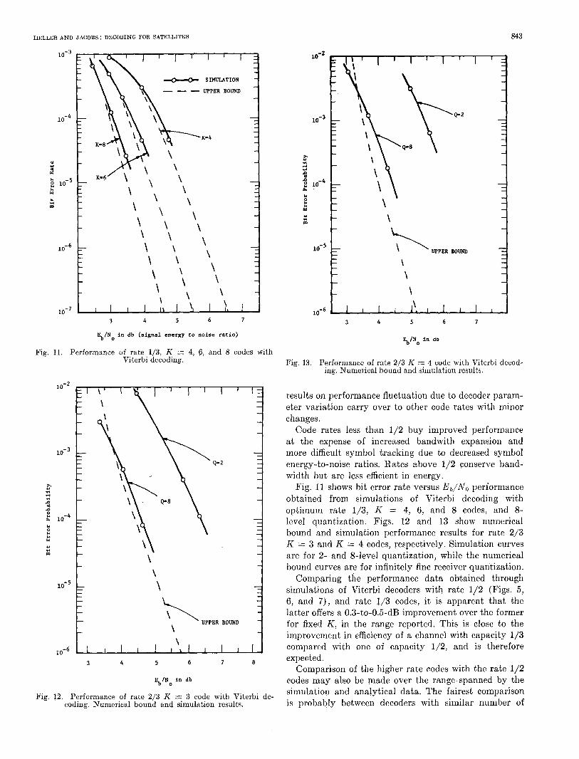
Fig. 11. Performance of rate 1/3, K = 4, 6 , and 8 codes with Viterbi decoding.
10-2
x 4 rl
n n e 10-4 I4
L4 P
4J 4 m
\ \
UPPER B O W \ \
10-6 1 I 1 I I i l I I I I
3 4 5 6 7 8
Eb/No in db
Fig. 12. Performance of rate 2/3 K = 3 code with Viterbi de- coding. Numerical bound and simulation results.
\
UPPER BOUND
\ \ \
Fig. 13. Performance of rate 2,/3 K = 4 code with Viterbi decod- ing. Numerical bound and simulation results.
results on performance fluctuation due to decoder param- eter va,riation carry over to other code rates with minor changes.
Code rates less than 1/2 buy improved performance at the expense of increased bandwith expansion and more difficult symbol tracking due to decreased symbol energy-to-noise ratios. Rates above 1/2 conserve band- width but are less efficient in energy.
Fig. 11 shows bit error rate versus E,/No performance obtained from simulations of Viterbi decoding with optimum rate 1/3, K = 4, 6, and 8 codes, and 8- level quantization. Figs. 12 and 13 show numerical bound and simulation performance results for rate 2/3 K = 3 and K = 4 codes, respectively. Simulation curves are for 2- and 8-level quantization, while the numerical bound curves are for infinitely fine receiver quantization.
Comparing the performance data obtained through simulations of Viterbi decoders with rate 112 (Figs. 5 , 6 , and 7 ) , and rate 1/3 codes, it is apparent that the latter offers a 0.3-to-0.5-dB improvement over the former for fixed K , .in the range reported. This is close to the improvement in efficiency of a channel with capacity 1/3 compared with one of capacity 1/2, and is therefore expected.
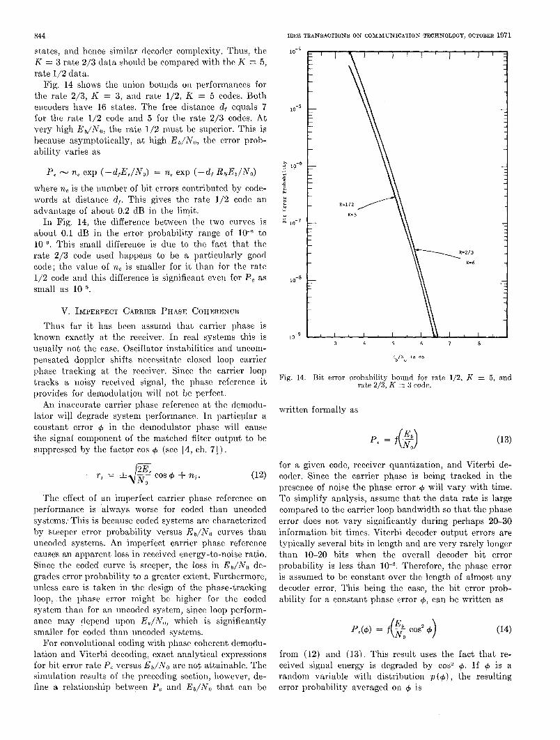
Comparison of the higher rate codes with the rate 1/2 codes may also be made over the range spanned by the simulation and analytical data. The fairest comparison is probably between decoders with similar number of
844
states, and hence similar decoder complexity. Thus, the K = 3 rate 2/3 data should be compared with the K = 5, rate 1J2 data.
Fig. 14 shows the union bounds on performances for the rate 2/3, K = 3, and rate 1/2, K = 5 codes. Both encoders have 16 states. The free distance d f equals 7 for the rate 1/2 code and 5 for the rate 2/3 codes. At very high EbjNO, the rate 1/2 must be superior. This is because asymptotically, a t high Eb/MO, the error prob- ability varies as
IEEE TRANSACTIONS ON COMMUNICATION TECHNOLOGY, OCTOBER 1971
1 0 - ~ I )
P, - ne exp (-d,E,/NJ = n, exp ( - 4 RNEb/NO) where ne is the number of bit errors contributed by code- words a t distance df. This gives the rate l /2 code an advantage of about 0.2 dB in the limit.
In Fig. 14, the difference between tho two curves is about 0.1 dB in the error probability range of to
This small difference is due to the fact that the rate 2/3 code used happens to be a particularly good code; the value of n, is smaller for i t than for the rate 1/2 code and this difference is significant even for F , as small as lo-”.
V. IMPERFECT CARRIER PHASE COYERENCE
Thus far it has been assumd that carrier phase is kuown exactly at the receiver. I n real systems this is usually not the case. Oscillator instabilities and uncom- pensated doppler shifts necessitate closed loop carrier phase tracking at the receiver. Since the carrier loop tracks a noisy received signal, the phase reference it provides for demodulation will not be perfect.
An inaccurate carrier phase reference at the demodu- lator will degrade system performance. In particular a constant error + in the demodulator phase will cause the signal component of the matched filter output to be suppressed by the factor cos + (see [4, ch. 71) .
The effect of an imperfect carrier phase reference on performance is ‘always worse for coded than uncoded systems: This is because coded systems are characterized by steeper error probability versus E,/N,, curves than uncoded systems. An imperfect carrier phase reference causes an apparent loss in received energy-to-noise ratio. Since the coded curve is steeper, the loss in Eb/No de- grades error probability to a greater extent. Furthermore, unless care is taken in the design of the phase-tracking loop, the phase error might be higher for the coded system than for an uncoded system, sipce loop perform- ance may depend upon E8/1V,,, which is significantly smaller for coded than uncoded systems.
For convolutional coding with phase coherent demodu- lation and Viterbi decoding, exact analytical expressions for bit error rate P, vcrsus Eb/lVO are not attainable. The simulation results of the preceding section, however, de- fine a relationship between P, and Eb/NO that can be
,x 10-6 r(
P
c P
0
w Y
IO-’
10-8
3 4 5 6 7 8
C b l l u i n db
Fig. 14. Bit error probability bound for rate 112, K = 5 , and rate 2/3, K = 3 code.
written formally as
P, = f(?) for a given code, receiver quantization, and Viterbi de- coder. Since the carrier phase is being tracked in the presence of noise the phase error + will vary with time. To simplify analysis, assume that the data rate is large compared to the carrier loop bandwidth so that the phase error does not vary significantly during perhaps 20-30 information. bit times. Viterbi decoder output errors are typically several bits in length and are very rarely longer than 10-20 bits when the overall decoder bit error probability is less than Therefore, the phase error is assumed to be constant over the length of almost any decoder error. This being the case, the bit error prob- ability for a constant phase error +, can be written as
from (12) and (13j. This result uses the fact that re- ceived signal energy is degraded by cos2 +, If + is a random variable with distribution p (+) , the resulting error probability averaged on + is
HELLER AND JACOBS: DECODING FOR SATELLITES 845
3 4 5 6 7 8 9 10 11 12 1 3 1 4 1 5
Eb/No in d b
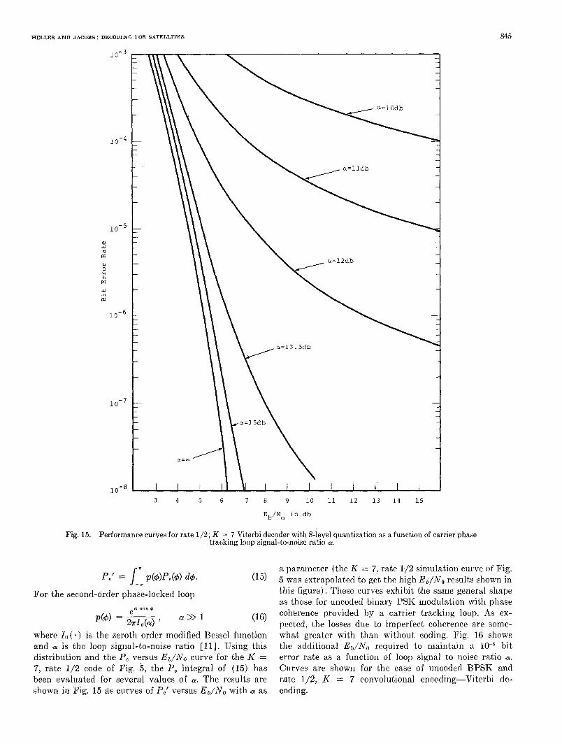
Fig. 15. Performance curves for rate 1/2; K = 7 Viterbi decoder with 8-level quantization as a function of carrier phase tracking loop signal-to-noise ratio a.
For the second-order phase-locked loop _ a C O R m
a >> 1
where I , ( - ) is the zeroth order modified Bessel function and ,(Y is the loop signal-to-noise ratio [ll]. Using this distribution and the P, versus E b / N o curve for the K '= 7, rate 1/2 code of Fig. 5 , the P, integral of (15) has been evaluated for several values of (Y. The results are shown in Fig. 15 as curves of P,' versus Eo/No with as
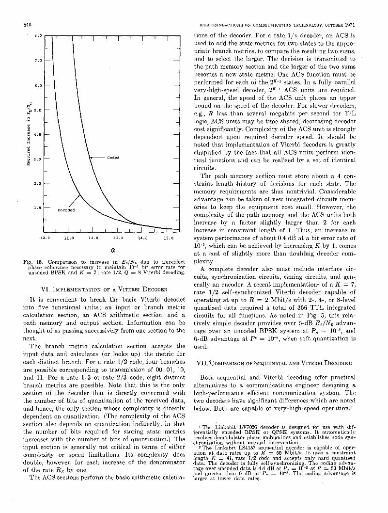
a parameter (the R = 7, rate 172 simulation curve of Fig. 5 was extrapolated to get the high E6/NO results shown in this figure). These curves exhibit the same general shape as those for uncoded binary PSK modulation with phase coherence provided by a carrier tracking loop. As ex- pected, the losses due to imperfect coherence are some- what greater with than without coding. Fig. 16 shows the additional E b / N o required to maintain a bit error rate as a function of loop signal to noise ratio .a. Curves are shown for the case of uncoded BPSK and rate l/i, K = 7 convolutional encoding-Viterbi de- coding.
846 IEEE TRANSACTIONS ON COMMUNICATION TECHNOLOGY, OCTOBER 1971
tions of the decoder. For a rate l / w decoder, an ACS is used to add the state metrics for two states to the appro- priate branch metrics, to compare the resulting two sums, and to select the larger. The decision is transmitted to the path memory section and the larger of the two sums becomes a new state metric. One ACS function must be performed for each of the 2K-1 states. In a fully parallel very-high-speed decoder, 2K-1 ACS units are required. I n general, the speed of the ACS unit places an upper bound on the speed of the decoder. For slower decoders, e.g., R less than several megabits per second for T2L logic, ACS units may be time shared, decreasing decoder cost significantly. Complexity of the ACS unit is strongly dependent upon required decoder speed. It should be noted that implementation of Viterbi decoders is greatly simplified by the fact that all ACS units perform iden- tical functions and can be realized by a set of identical circuits.
The path memory section must store about a 4 con- straint length history of decisions for each state. The memory requirements are thus nontrivial. Considerable advantage can be taken of new integrated-circuits mem- ories to keep the equipment cost small. However, the complexity of the path memory and the ACS units both ’increase by a factor slightly larger than 2 for each increase in constraint length of 1. Thus, an increase in system performance of about 0.4 dB a t a bit error rate of
which can be achieved by increasing K by 1, comes a t a cost of slightly more than doubling decoder com- plexity.
A complete decoder also must include interface cir- cuits, synchronization circuits, timing circuits, and gen: erally an encoder. A recent implementation1 of a K = 7, rate 1/2 self-synchronized Viterbi decoder capable of operating at up to R = 2 Mbit/s with 2-, 4-, or 8-level quantized data required a total of 356 TTL integrated circuits for all functions. As noted in Fig. 5, this rela- tively simple decoder provides over 5-dB E b / N o advan- tage over an uncoded BPSK system a t P, = and 6-dB advantage at PC = when soft quantization-is used.
zo ‘a
c .rl
10.0 11.0 12.0 13.0 14.0 15.0
a Fig. 16. Comparison to increase in Ea/No due to imperfect
phase, coherence necessary to maintain 10-5 bit error rate for uncoded BPSK and K = 7; rate 1/2, Q = 8 Viterbi decoding.
VI. IMPLEMENTATION OF A VITERBI DECODER It is convenient to break the basic Viterbi decoder
into five functional units; an input or branch metric calculation section, an ACS arithmetic section, and a path memory and output section. Information can be thought of as passing successively from one section to the next.
The branch metric calculation section accepts the input data and calculates (or looks up) the metric for each distinct branch. For a rate 1/2 code, four branches are possible corresponding to transmission of 00, 01, 10, and 11. For a rate 1/3 or rate 2/3 code, eight distinct branch metrics are possible. Note that this is the only section of the decoder that is directly concerned with the number of bits of quantization of the received data, and hence, the only section whose complexity is directly dependent on quantization. (The complexity of the ACS section also depends on quantization indirectly, in that the number of bits required for storing state metrics increases with the number of bits of quantization.) The input section is generally not critical in terms of either complexity or speed limitations. I ts complexity does double, however, for each increase of the denominator of the rate R N by one.
The ACS sections perform the basic arithmetic calcula-
VII.’COMPARISON OF SEQUENTIAL AND VITERBI DECODING
Both seqhential and Viterbi decoding offer practical alternatives to a communic,ations engineer designing a high-performance efficient communication system. The two decoders have significant differences which are noted below. Both are capable of very-high-speed operation.2
ferentially encoded BPSK or QPSK systems. It automatically 1 The Linkabit LV7026 decoder is designed for use with dif-
resolves demodulator phase ambiguities and establishes node syn- chronization without manual intervention.
ation at data rates up to R = 50 Mbit/s. It uses a constraint 2 The Linkabit LS4157 sequential decoder is capable of oper-
length K = 41, .rate 1/2 code and accepts only hard quantized data. The decoder is fully self-synchronizing. The coding advan- tage over uncoded data is 4.4 dB at P , = 10-5 at R = 50 Mbit/s
larger at, lower d a h rates. and greater than 6 dB a t P , = 10-*. The coding advantage is
HELLER A N D JACOBS: DECODING FOR SATELLITES
A. Error Probabilit!j I t should be recalled that, since the complexity of se-
quential decoders is relatively independent of constraint length, the constraint length is typically made quite large to provide a very small probability of undetected error. Usually the important contributor of errors is received data buffer overflow due to a computational overload. Such an event causes a long burst of rather noisy output data until the decoder reestablishes code synchronization. During this burst, the probability of bit error is that of the raw channel, perhaps PC = 3 x
Error from a Viterbi decoder occurs in short bursts of length a t most 10 to 20. Systems that are sensitive to long bursts of errors should thus use Viterbi decoding. Systems that can tolerate occasional long bursts, with an error indication provided if desired by the decoder, should consider sequential decoding.
The curve of error probability versus E,/No tends to be much steeper for a sequential decoder than for a Viterbi decoder because of the differencc in I<. Thus, the sequential decoding advantage tends to increase as lower probabilities of bit crror are demanded, although, as before, many errors tend to come in widely separated noisy bursts.
R. Decoder Delay Sequential decoders tend to require long buffers of
a t least 200 bits and as much as several thousand bits to smooth out the variations in computational load. Viterbi decoders require a path memory of a t most 64 bits. Thus the decoding delay differs by u p to two orders of magnitude.
C. Long Tail Required to Terminate Sequences In time-division multiplexed systems, bursts of sepa-
rately encoded data may be received at the same decoder from different sources. In these instances, it may be de- sirable to time share the decoder. As noted in Section 111, termination of encoding can be achieved by transmitting a known sequence of length K - 1, thus causing the encoder to enter a known state. Since K is typically larger for sequential decoding, the “tailing off” of the encoded sequence can cause a significant degradation. in system efficiency. The tailing off of the short Constraint length codes for Viterbi decoding causes a much smaller degradation.
If time and implementation permit the storage of the decoder state without code termination, then the cost of tailing off can be ignored. The design of such a time- shared sequential decoder remains for future work.
D. Rates Other than 1/2 and soft Quantization Viterbi decoders for rate 1/3 and 8-level quantization
are not significantly more complex than those for rate 1/2 and 4- or 2-level quantization. The chief costs occur in the input section of the decoder as discussed in Section VI. In particular, the soft quantized data are processed in the input section and then incorporated in the branch
847
and state metrics. No storage is required. A sequential decoder, on the other hand, must store several thousand branches of received data, each branch containing log? &/RAT bits for rate R N and Q level quantization. Al- though the possibility exists of gaining 0.4 dB by using rate 1/3 rather than rate 1/2 and of gaining 2 dB by using soft decisions rather than hard, these advantages are bought in sequential decoding a t a formidable storage and processing cost. In general, then, practical high-rate sequential decoders are limited to rate 1/2 and hard decisions. (It is conceivable that this cost could be min- imized by operating the dec.oder a t a very high ratio of computation rate to average bit rate, thereby minimizing the number of branches required in the buffer.)
A second argument against soft quantization with sequential decoding involves the sensitivity of the prob- ability of buffer overflow to channel variations. In Fig. 10, i t was demonstrated that changes in receiver AGC of *20 percent had negligible effect on the performance of a Viterbi decoder. The degradation is much more pronounced for sequential decoding, since the computa- tional load is very sensitive to changes in channel param- eters. Thus, part of the 2-dB gain anticipated for soft decisions might be lost unless great care was exercised in controlling receiver AGC precisely.
In comparing sequential decoding and Viterbi decod- ing, it thus appears fair to consider soft decisions only for the Viterbi decoder. Under these conditions, the efficiency advantage of a long c,onstraint length se- quential decoder is considerably diluted. Consequently, performance of a rate 1/2, K = 41 sequential decoder is no better than a rate 1/2 Viterbi decoder of con- straint length 5 to 7 (depending on the speed factor, that is, the ratio of computation rate to bit rate) at a P , of
The sequential decoder does show a distinct ad- vantage for P, of 1k8 or smaller.
On the other hand, building a system without receiver quantization lowers system costs, since a considerably more crude AGC may be used.
E. Sensitivity to Phase Error and Rtcrsty Conditions on the Channel
The performance of Viterbi decoding under slowly fluctuating phase error was presented in Fig. 15. A similar calculation would indicate much greater degrada- tion in the case of sequential decoding, since the error probability curve is much steeper. Furthermore, this estimate would be optimistic in the case of sequential decoding, since the assumption that the phase varied so slowly that errors occurred independently would prob- ably not hold for sequential decoding. Thus, more care- ful design of the phase-tracking loop is indicated for a system utilizing sequential decoding rather than Viterbi decoding.
VIII. CONCLUSIONS Viterbi decoding has been shown to be a practical
method for improving satellite and space communication
848
efficiency by 4-6 dB, a t a. bit error rate of lo+. The successful implementation of 2-Mbit/s constraint-length-7 Viterbi decoders effectively demonstrates that the tech- nique is well beyond the stage of being a theoretical curiosity. In fact, a major effort has heen under u7ay for the past 2-3 years with the aim of modifying and adapting the algorithm for minimum complexity imple- mentation without sacrificing performance significantly.
I n addition, Viterbi decoding has been shown to “de- grade gracefully” in the prescncc of advcrse channel or receiver conditions. In particular, the error probability does not change precipitously with E b / N o as is the case with coding techniques that use longer codes and/or require variable decoding effort, such as sequential de- coding. This ensures that performance‘ degradation due to an imperfect phase or bit timing reference, or a slight correlation between noise samples, will be minimal. Re- quirements on AGC accuracy, even : for ‘soft decisions, were shown to be quite loose.
Finally the results presented here should provide the communication engineer with the information necessary to evaluate the applicability of Viterbi decoding to space and satellite communication systems with a wide range of requirements and constraints.
REFERENCES
111
121
[31
141
[51
[SI
171
C. E . Shannon, “Communication is the presence of noise,” Proc. IRE, vol, 37, Jan. 1949, pp. 10-21. Codex Corp., Final Rep. “Coding system design for ad- vanced solar missions,’? Contract NAS 2-3637, NASA Ames Res. Cent., M0ffet.t Field, Calif.
in communication systems, this issue, pp. 751-772. A. J. Viterbi, “ConvolutioEal codes and their performance
J. M. Wozencraft and I . M. Jacobs, Pritbciples of CowLmu- 7aication Engitreering. New York : Wiley, 1965. I. M. Jacobs. “Sequential decoding for efficient communi-
val. COM-15, Aug. 1967, pp. 492-501. cation from deep space,” IEEE Trans. Commun. Technol.,
A. J. Viterbi, “Error bounds for convolutional codes and an asymptotically optimum decoding algorithm.” IEEE T ~ t n s .
J. A. Heller, “Short constraint length convolutional codes,” Inform. Theory, vol. IT-13, Apr. 1967, pp. 260-269.
Jet Propulsion Lab., California Inst. Technol., Space Pro- grams Summary 37-54, vol. 111, Oct./Nov.. 1968, pp. 171- .I_
111. 181 -. “Improved performance of short, constraint, length
convolutional codes,” Jet Propulsion Lab., California Inst. Technol., Space Programs Summary 37-56, vol. 111, Fcb./
[91 Linkabit Corp., Final Rep., “Coding systems study for high Mar. 1969. pp. 83-84.
data rate telemetry links,” Contract NAS2-6024, NASA Ames Res. Ctr. Rep. CR-114278, Moffett Field, Calif.
[lo] J. P. Odenwalder, “Optimum decoding of convolutional codes,” Ph.D. dissertation, Syst. Sei. Dep., Univ. Californla,
1111 A. J . Viterbi, Principles of Coherent Communicnlion. New Los Angeles, 1970.
York : McGraw-Hill, 1966.
IEEE: TRANSACTIONS ON COMMUNICATION TECHNOLOGY, OCTOBER 1971
[121 J . K. Omura, “On the Viterhi decoding algorithm,” ZEEE Trans. In form. Theory (Corresp.), vol. IT-15, Jan. 1969, pp. 177-179.
Jerrold A. Heller (M’68) was born in New York, N. Y., on June 30, 1941. He received the B.E.E. degree in 1963 from Syracuse University, Syracuse, N. Y., and the M.S. and Ph.D. degrees in electrical engineering from the Massachusetts Institute of Tech- nology, Cambridge, in 1964 and 1967, re- spectively. During his first year at M.I.T. he was a National Science Fonndation Fellow.
In 1965 he joined the M.I.T. Research Laboratory of Electronics where he was a Xerox Fellow for the following two years. He held summer positions in 1962 at the Bell Telephone Laboratories, New York, N. Y . , and in 1963 at the IBM Research Center, Yorktown Heights, N. Y., where he worked on the logical design of digital systems. From 1967 to 1969 he was with the Communications Research Section of the Jet Propulsion Laboratory, Pasadena, Calif., where his work centered on the application of coding to deep-space communication. He is presently Director of Technical Operations for the Linkabit Corporation, San Diego, Calif. Currently, his work is concerned with coding for space, €IF, and communication satellite channels.
Dr. Heller is a member of Tau Beta Pi, Et,a Kappa Nu, and Sigma Xi.
Irwin Mark Jacobs (S’55-M’60) was born in New Bedford, Mass., on October 18, 1933. He received the B.E.E. degree from Cornell University, Ithaca, N. Y., in 1956, and the S.M. and Sc.D. degrees from the Massachu- setts Institute of Technology, Cambridge, in 1957 and 1959, respectively. He was the recipient of a McMullin Regional Scholar- ship and a General Electric Teachers Con- ference Scholarship at Cornell and par- ticipated in the engineering cooperative
Buffalo, N. Y. In graduate school, he was a General Electric Fellow program in association with the Cornell Aeronautical Laboratory,
and an Industrial Fellow of Electronics. In 1959, he was appointed Assistant Professor of Electrical
Engineering at M.I.T. and was a Member of the staff of the Re- search Laboratory of Electronics. He was promoted to Associate Professor in 1964. On leave from M.I.T., he spent the academic year 1964-1965 as a NASA Resident Research Fellow at the Jet Propulsion Laboratory, Pasadena, Calif., and was concerned principally with coding for deep-space communications. In 1966, he accepted an appointment as Associat,e Professor of Applied Physics and Information Science at the University of California, San Diego. I n 1970 he was promoted to full Professor. I n 1968 he cofounded Linkabit Corporation, of which he is now President. He is presently on leave from the University of California and devoting full time t,o Linkabit Corporation. He is currently working in the area of information and computer science.
Dr. Jacobs is a member of Phi Kappa Phi, Sigma Xi, Eta Kappa Nu, Tau Beta Pi, and the Association for Computing Machinery.