Embed Size (px)
Citation preview

124
Physical Interfaces in the Electronic Arts
Interaction Theory and Interfacing Techniques for Real-time Performance
Bert Bongers
Engineering Design Centre
University of Cambridge
l
P r i n t t h i s a r t i c l e
125
Introduction
This paper takes two approaches to describe aspects of physical interfaces in the electronic arts. Oneapproach takes a Human Factors point of view of the different interactions that can take place in electronicart, and the other more practical approach describes sensor technologies (and a sensor categorisation) tomake the physical interaction possible.
In this introduction the historical development of the ergonomic aspects of the design of instruments aredescribed.
Because the earliest examples of the usage of electronic media to make art can be found in music, andbecause music has a long tradition of performance and of a precise and intimate relationship betweenhuman and technology, this paper often takes electronic musical instruments as a starting point. From there,the paper aims to describe the general field of art forms using electronics (visual arts, installations,architecture, network, music).
Humans have always been making music by using objects and artefacts. Every known way of generatingsound, using strings, bells, reeds etc. has been used to make musical instruments. In all stages of engineering(manual / mechanical / electromechanical / electronic / digital) the technology was reflected in theinstruments. The nature of the sound generating process traditionally dictated the design of the instrument.Take for instance bowing a string. On a violin the strings are short and therefore fit on an instrument that isheld under the player's chin. Longer strings to reach lower registers called for a bigger instrument, forinstance the cello that rests with a pin on the ground and is held between the player's knees. Even longerand thicker strings for bass notes demands such a big instrument that the player has to stand next to it andembrace it. In instruments that use electricity in any form this relationship is often less clear.
The Ergonomics of Electronic Instruments
Soon after electricity was discovered people started to use this new medium to generate sound. When theelectrical sciences became more serious and the grasp of humankind on this new medium enabled thebuilding of all sorts of devices for communication, the electrical instruments became more sophisticated andin the first half of the 20th century a lot of new instruments sprung up. Most of them where based on akeyboard, which had proven to be a versatile interface since it can be found for centuries on a variety ofinstruments like the piano, harpsichord, organ, etc. There were interesting exceptions of course, like thewell known Theremin which operates with gesture-sensitive antennas changing pitch and volume of a tonegenerated by an oscillator [Martin, 1995]. Another example is the Trautonium, which works with a touchsensitive strip. Of the instruments that did use the keyboard as their main interface part, like the ondes

126
Martenot (France) [Ruschkowski, 1990] and the Electronic Sackbutt (Canada) [Young, 1984], most used avariety of additions to enhance the sensitivity. A good overview of the early days of electronic music (andthe business aspects of it) can be found in Joel Chadabe's book [1997].
Instrument designers like Leon Theremin, Maurice Martenot, Oskar Sala and Hugh Le Caine seemed toexploit the freedom of design offered by the new medium, which imposed far less on the design of theshape and dimensions of the instrument than the traditional instruments did. They could take the properties
and possibilities (and limitations) of the human being as a starting point for the design
1
. At the same time alot had to be developed on the sound synthesis side, and also the invention and usage of the record playerand later the tape machines in electronic music led to the field turning away from real-time musicperformance.
The Ergonomics of Digital Instruments
For many years, the keyboard and a number of knobs were the standard interface objects for makingelectronic music. Today there is a wide (if not to say wild) variety of sensors available. Virtually any real-world action can be translated into electrical energy and therefore serve as a control signal for an electronic(analog or digital) sound source.
Although the advent of digital technologies brought us even more ways of synthesizing sounds (andsampling as a convenient way of recording, manipulating and playing back sounds), the distance betweencontroller and that which is controlled became even bigger. The introduction of the MIDI protocol aroundthe mid-eighties detached the control device (the interface or instrument) from the sound source, whichwidened the gap even further but also introduced new possibilities. It became possible to developalternative MIDI-controllers, which could be entirely new forms based on humans rather than on thetechnology. In a way, one could argue that it is only the most obvious thing to do - devise instrument formsespecially for this medium. Michel Waisvisz was an early example, inventing his "Hands" around 1983[Waisvisz, 1985, 1999], and he still emphasises that in fact the piano keyboard should be regarded as thealternative controller for electronic instruments. [Steinglass, 1999].
MIDI controllers also became available in many known instrument forms (like the guitar and several windinstruments) to enable musicians already proficient on these traditional instrument forms to use their skillsand playing techniques. Hybrid forms came about as well. In this paper these categories will be describedand illustrated with examples of instruments and installations built and / or developed by the author.
1. This was even before Ergonomics or Human Factors was established as a serious field of research around 1950!
127
The question of how to deal with the total freedom of being able to design an instrument based on thehuman (in)capabilities instead of a traditional instrument form, has not been answered yet. A suggestedapproach is to look at the most sensitive effectors of the human body, such as the hands and the lips, whichalso have the finest control, and look at the gestures and manipulations that humans use in traditionalinstruments or in other means of conveying information.
Tactual Feedback
Due to the decoupling of the sound source and control surface, a lot of
feedback
from the processcontrolled was lost. In electronic musical instruments, the main sense addressed is the auditory through thesounds produced. Visual feedback of more analytic parameters is often displayed on LCD screens. But thetouch feedback from the sound source is hardly used, the feel of a key that plays a synthesized tone willalways be the same irrespective of the properties of the sound (the device can even be turned off entirely!).
Some work has been carried out (partly borrowing from the research fields of Human-Computer Interaction(HCI) and Virtual Environments) on addressing the sense of touch, to restore the relationship between thatwhich is felt and the sounds produced. This is an important source of information about the sound, and theinformation is often sensed at the point where the process is being manipulated (at the fingertips or lips).This can be described as articulatory feedback.
Conclusion
This paper consist of two parts. The next chapter outlines a general framework to classify interaction in theelectronic arts, and the last chapter describes techniques and technologies (the nuts and bolts) of how tobuild these interactions. Throughout the paper examples are used of instruments I have built, or projects Iwas involved in. It is therefore work in progress, I intend to keep updating the paper with knowledge Iacquire after this publication.
With the technologies described in this chapter the design of electronic musical instruments anddevelopment of interfaces for visual arts can be based on human beings rather then on the technology. Thisway, we hope to achieve maximum sensitivity along many dimensions (or degrees of freedom), withprofound feedback addressing many sensory modalities.

128
Interaction in Performance Arts
There are many interactions possible between performer, (electronic) system and audience, involving variousmodes of communication. In this chapter, a concise overview and theoretic framework based on researchmainly carried out in the field of HCI (Human-Computer Interaction) is described. The approach describedfocuses on the physical interaction between people and systems, rather then the interactive behaviour as aresult of machine cognition.
Interaction between a human and a system is a two way process:
control
and
feedback
. The interaction takesplace through an interface (or instrument) which translates real world actions into signals in the virtualdomain of the system. These are usually electric signals, often digital as in the case of a computer. Thesystem is controlled by the user, and the system gives feedback to help the user to articulate the control, orfeed-forward to actively guide the user. Feed forward is generated by the system to reveal informationabout its internal state.
In this chapter the interaction between humans and electronic systems is described in general, and theninteraction is grouped and described in three categories: performer - system (e.g. a musician playing aninstrument), system - audience (e.g. installation art), and performer - system - audience. The directinteraction between the performer and audience can always be present, but this paper focuses on theinteraction mediated by an electronic system. The interaction between multiple performers as in anensemble or band, even when it is mediated by a system (for instance The Hub or the Sensorband networkconcerts [Bongers, 1998b]), is not addressed in this paper.
The categories will be illustrated by projects where the author was involved as an instrument builder orinteraction researcher.
129
Human-Machine Interaction
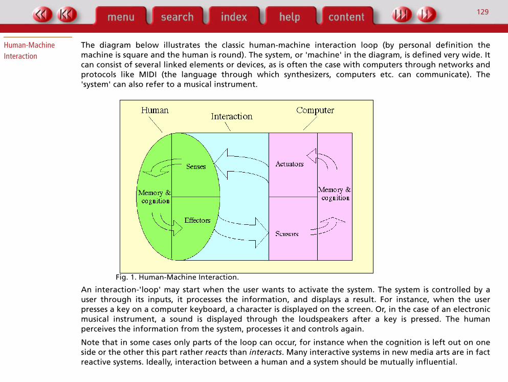
The diagram below illustrates the classic human-machine interaction loop (by personal definition themachine is square and the human is round). The system, or 'machine' in the diagram, is defined very wide. Itcan consist of several linked elements or devices, as is often the case with computers through networks andprotocols like MIDI (the language through which synthesizers, computers etc. can communicate). The'system' can also refer to a musical instrument.
Fig. 1. Human-Machine Interaction.
An interaction-'loop' may start when the user wants to activate the system. The system is controlled by auser through its inputs, it processes the information, and displays a result. For instance, when the userpresses a key on a computer keyboard, a character is displayed on the screen. Or, in the case of an electronicmusical instrument, a sound is displayed through the loudspeakers after a key is pressed. The humanperceives the information from the system, processes it and controls again.
Note that in some cases only parts of the loop can occur, for instance when the cognition is left out on oneside or the other this part rather
reacts
than
interacts
. Many interactive systems in new media arts are in factreactive systems. Ideally, interaction between a human and a system should be mutually influential.

130
The systems communicates with its environment through
transducers
, devices that transduce (translate) real-world signals into machine-world signals (
sensors
) and vice versa (
actuators
).
Sensors
are the sense organs of a machine. Through its sensing inputs, a machine can communicate with itsenvironment and therefore be controlled. A sensor converts any physical energy (from the outside world)into electricity (into the machine world). There are sensors available for all things perceivable by humanbeings, and more. For instance, kinetic energy (movement), light, sound, but also properties unperceivablefor human beings can be sensed such as electromagnetic fields and ultrasonic sound. Sensors are describedin the next part of this paper.
Machine output takes place through
actuators
. Actuators are the opposite of sensors, i.e., they convertelectrical energy from the machine world into other energy forms for instance those perceivable by humanbeings. For instance, a loudspeaker converts electricity in changes in air pressure perceivable by the humanear, a video display shows images perceivable by the eye, motors or vibrating piezo elements may addressthe sense of touch. The interaction usually takes place by means of an interface (instrument). Following thedefinitions of the diagram, the interface is part of the system or machine and consists of the sensors and
actuators.
2
2. This notion is challenged by the SciFi term 'cyborgs' (Cybernetic Organism), where interfaces become part of the human body. This work is carried out in scientific research, as well as in the arts (e.g. the Australian performance artist Stelarc).

131
Modalities
Several interaction
modalities
, or communication channels, can be distinguished. Modalities are closelyrelated to perception and motor control: the visual input modality for seeing things, the auditory inputmodality for hearing things, or the manual output modality where the human physically controls things.
Fig. 2. Examples of modalities.
Other examples of
sensory modalities
are: smell, taste and touch. Within each sensory modality other(sub)modalities can be distinguished, for instance the visual modality can be used for reading text, reading amusical score or watching a movie.
The human sense of touch (tactual perception) differs in an important way from our other senses in that itgathers most information about the outside world mainly by active explorations. In contrast to sound forinstance, which is very hard for us to even neglect, we perceive object dimensions and properties often onlyby reaching out and touching them, and moving around the surface. Understanding the sense of touch isimportant for the work on physical interaction as described in this paper. The sense of touch actually consistsof three main senses, which are often difficult to separate. Tactile perception receives its informationthrough the
cutaneous
sensitivity of the skin, when the human is not moving.
Proprioceptors
(mechanoreceptors that sense forces in the muscles, tendons and joints) are the main input for ourkinaesthetic sense, which is the awareness of movement, position and orientation of limbs and parts of the
132
human body. Haptic perception uses information from both the tactile and kinaesthetic senses. Themovement sensed by the kinaesthetic or haptic sense can be a result of actions from the human (activetouch, which involves the perception of the signals the brain sends to the muscles), or from forces outsidethe body (passive touch).
Active haptic perception, when actively gathering information about objects outside of the body, is the mainsense that can be applied in interfaces.
The tactile, kinaesthetic and haptic perception together, is called
tactual perception
as defined by Loomis &Leederman [1986] building on the seminal work of J.J. Gibson in the fifties.
Human
output modalities
mainly involve the motor system; muscles are used to move things around but arealso used for finer tasks such as handwriting and speech. A special case is bio-electricity, such aselectromyographic signals (EMG) as measured on the skin which are related to muscle activity, andelectroencephalographic signals (EEG) related to brain activity (e.g. alpha waves). These signals can be canbe measured by electrodes and used to control a system, a good description can be found in a paper by TomZimmerman et al, [1995] and Hugh Lusted and Benjamin Knapp [1996]. Bio-electricity is used for musicalperformance for instance by Atau Tanaka of Sensorband [Tanaka, 1993], [Bongers, 1998b] [Editors’ note: seethe article by Tanaka in this volume].
Michel Waisvisz was an early pioneer, using galvanic skin response (the changing electrical resistance of theskin) by sticking his fingers into (analog) electronics directly, resulting in the well-known Crackle boxes[Krefeld, 1990].
Some activities or interactions can be
multimodal
, in fact, most activities in everyday life involve multiplemodalities. For instance, eating may involve a combination of
taste
(the four tastes of sweet, bitter, sour orsalt),
smell
and
touch
(texture, form, softness).
Virtuality
In addition to the diagram above, it is relevant to emphasise the distinction between
active
and
passive
system feedback. For instance, when pressing a button on an electronic device, one may feel and hear themechanical 'click' regardless of the state of the device. The device can even be turned off and still thefeedback is perceived. This key click can be called passive or inherent feedback, i.e. not generated by thesystem. In the case of a synthesizer, the sounds produced by the system as a result of the user action areactive, i.e. generated by the system (controlled by the performer). Synthesized experiences are also called
virtual
, as opposed to real (mechanical, inherent or passive) experiences [Robinett, 1992]. An electronicsystem (often a computer) interface generates things that, through its output devices, can be perceived by

133
humans. These are virtual, because they are not really there but can be perceived and experienced. Forexample, one can listen to sounds generated by a system (synthesized, or sampled and played back). Otherexamples are computer generated images, or touch.
In order to synthesize a more convincing experience, multiple senses of the human could be addressed.These multimodal interfaces [Schomaker et al., 1995], [Bongers et al, 1998a] enable users to hear, see andfeel the virtual world and influence it in many ways including for instance speech.
The importance of the sense of touch in traditional musical instruments, as well as in tools used for other artforms, is well known. Due to the de-coupling of control and feedback in electronic systems, this form ofinformation about the process is often lost. Ultimately, the 'feel' has to be synthesized artificially, just as thesounds and images are synthesized by such a system. This is described in another paper [Bongers, 1998c].
Performer - System
The most common interaction in the electronic arts is the interaction between performer and the system.This can be the musician playing an electronic instrument, a painter drawing with a stylus on an electronictablet, or an architect operating a CAD (Computer Aided Design) program.
Electronic Musical Instruments
The communication between a musician and the instrument is often intimate and precise. This has been thecase with traditional (acoustic) instruments, and developers of electronic instruments often strive for thesame level of intimacy and precision.
Electronic versions of traditional instruments
Early examples of the electric guitar, invented by Leo Fender around 1950, are the Fender Telecaster andStratocaster and the Gibson Les Paul. These instruments offer new possibilities for playing, as pioneered byJimi Hendrix and Jaco Pastorius (on the electric bass guitar, an instrument invented by Fender), and newplaying techniques are still discovered. Another example is the Fender Rhodes, an electric piano.
Electric
instruments use the same sound production as their acoustic counterparts, but are electrically amplified.
Electronic
instruments are based on electronic sounds sources such as oscillators.
Many early attempts to make electronic musical instruments were based on copying traditional instrumentsforms. Yamaha, Roland and Syntaxxe pioneered with electronic guitars, Akai brought out the EWI(Electronic Wind Instrument, a saxophone) and the EVI (Electronic Valve Instrument, a trumpet). Otherexamples of the electronic saxophone are the Yamaha WX7 and the Lyricon (which worked with an analogsynthesizer). Not to mention the keyboard, which falls in this category as well.
134
These instruments were to different extents incredibly limited in sensitivity and expressiveness compared totheir acoustic (and electric!) counterparts, but this can be seen as a trade-off against the enormous range ofdifferent sounds. For a while, people were thrilled by the possibility of being able to play organ sounds on atrumpet, or flute sounds on a keyboard. This is a mixed blessing of course, because the relationship betweenthe controlling device and the sounds produced is distorted, a mismatch which can result in lack ofexpressiveness.
Alternate controllers
As stated earlier, it is possible to design instruments in entirely new forms. Several gestural controllers wereinvented, and instruments that (still) have to be touched. The Theremin is the earliest example of an gesturalcontroller, and the Thunder by Don Buchla is an example of an alternate controller that had to be touchedthrough a touch-control surface that reflects the human hand.
People started using electronic gloves, inspired by the success of the VPL Dataglove [Zimmerman et al, 1987]for use in virtual environments (the popular term is Virtual Reality [Rheingold, 1991]). Often the MattelPowerglove, a cheaper version intended for computer games [Gold, 1992] that came out in 1989, was usedfor these applications.
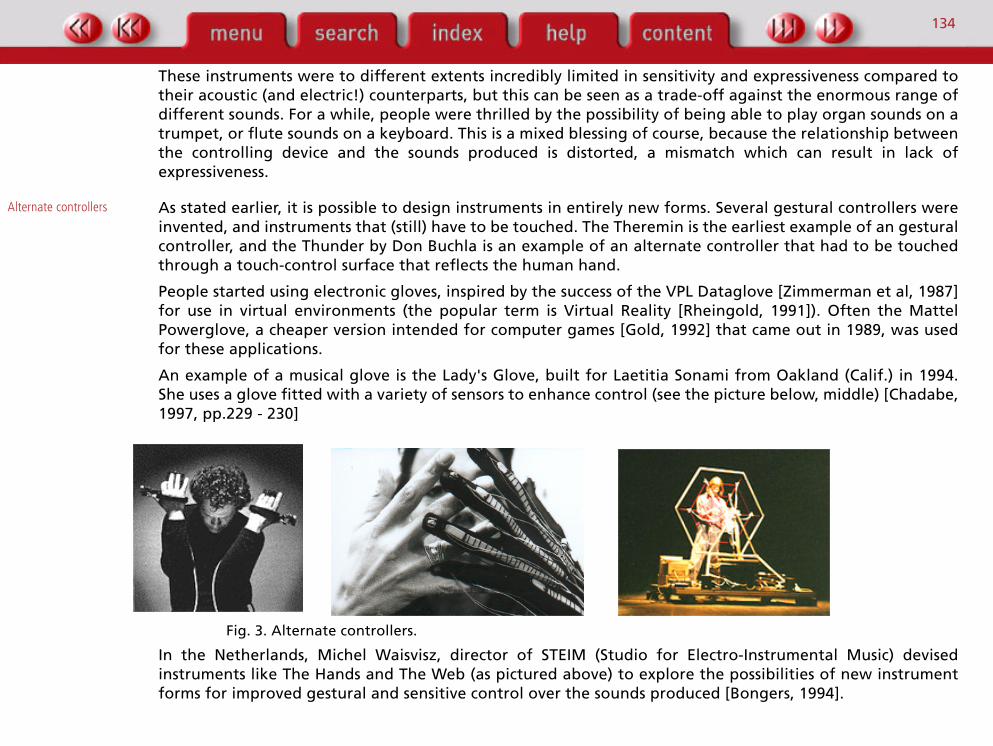
An example of a musical glove is the Lady's Glove, built for Laetitia Sonami from Oakland (Calif.) in 1994.She uses a glove fitted with a variety of sensors to enhance control (see the picture below, middle) [Chadabe,1997, pp.229 - 230]
Fig. 3. Alternate controllers.
In the Netherlands, Michel Waisvisz, director of STEIM (Studio for Electro-Instrumental Music) devisedinstruments like The Hands and The Web (as pictured above) to explore the possibilities of new instrumentforms for improved gestural and sensitive control over the sounds produced [Bongers, 1994].
135
Another example is the English composer and performer Walter Fabeck, who plays his Chromasone, andSensorband [1999], [Bongers, 1998b], a trio of musicians all playing on novel instruments.
Hybrid instruments
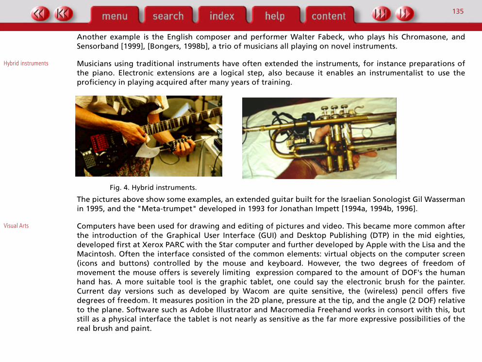
Musicians using traditional instruments have often extended the instruments, for instance preparations ofthe piano. Electronic extensions are a logical step, also because it enables an instrumentalist to use theproficiency in playing acquired after many years of training.
Fig. 4. Hybrid instruments.
The pictures above show some examples, an extended guitar built for the Israelian Sonologist Gil Wassermanin 1995, and the "Meta-trumpet" developed in 1993 for Jonathan Impett [1994a, 1994b, 1996].
Visual Arts
Computers have been used for drawing and editing of pictures and video. This became more common afterthe introduction of the Graphical User Interface (GUI) and Desktop Publishing (DTP) in the mid eighties,developed first at Xerox PARC with the Star computer and further developed by Apple with the Lisa and theMacintosh. Often the interface consisted of the common elements: virtual objects on the computer screen(icons and buttons) controlled by the mouse and keyboard. However, the two degrees of freedom ofmovement the mouse offers is severely limiting expression compared to the amount of DOF's the humanhand has. A more suitable tool is the graphic tablet, one could say the electronic brush for the painter.Current day versions such as developed by Wacom are quite sensitive, the (wireless) pencil offers fivedegrees of freedom. It measures position in the 2D plane, pressure at the tip, and the angle (2 DOF) relativeto the plane. Software such as Adobe Illustrator and Macromedia Freehand works in consort with this, butstill as a physical interface the tablet is not nearly as sensitive as the far more expressive possibilities of thereal brush and paint.
136
System - Audience
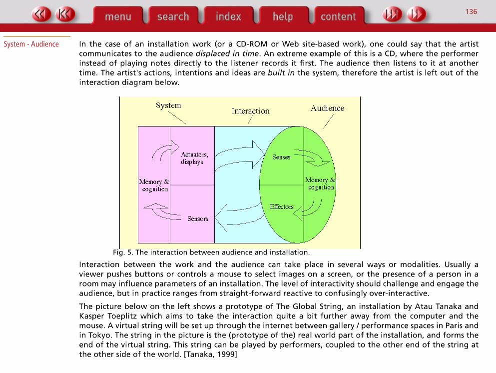
In the case of an installation work (or a CD-ROM or Web site-based work), one could say that the artistcommunicates to the audience
displaced in time
. An extreme example of this is a CD, where the performerinstead of playing notes directly to the listener records it first. The audience then listens to it at anothertime. The artist's actions, intentions and ideas are
built in
the system, therefore the artist is left out of theinteraction diagram below.
Fig. 5. The interaction between audience and installation.
Interaction between the work and the audience can take place in several ways or modalities. Usually aviewer pushes buttons or controls a mouse to select images on a screen, or the presence of a person in aroom may influence parameters of an installation. The level of interactivity should challenge and engage theaudience, but in practice ranges from straight-forward reactive to confusingly over-interactive.
The picture below on the left shows a prototype of The Global String, an installation by Atau Tanaka andKasper Toeplitz which aims to take the interaction quite a bit further away from the computer and themouse. A virtual string will be set up through the internet between gallery / performance spaces in Paris andin Tokyo. The string in the picture is the (prototype of the) real world part of the installation, and forms theend of the virtual string. This string can be played by performers, coupled to the other end of the string atthe other side of the world. [Tanaka, 1999]

137
Fig. 6. Two examples of installation work.
The picture on the right shows part of the interior of the Water Pavilion in Zeeland, The Netherlands. This isan interactive building, designed by architects Kas Oosterhuis and Lars Spuybroek (the part shown in thepicture). The audience can interact with the architecture by pushing against walls, entering hotspots, pullingropes and other ways. Sounds will change (also position) and projections (such as the grid visible in thepicture) change as if they were directly touched by the audience [Schwartz, 1997].
Another example is the electronic coffee-table book with built-in sensors I made for a research group at theUniversity of Amsterdam. This book plays music continuously (a rather annoyingly melody through a littlemicrochip as used in wishing cards), except when placed on the shelf or read up side down. When turning topage 105, the music stops so that the audience can read a poem (about accessibility) [de Jong, 1991].
138
Performer - System - Audience
Real interaction is a living two-way process of giving, receiving and giving back. In a traditional performanceset up the audience is passive, the performer active. The increasing use of "audience participation" in atraditional concert setting acknowledges the need but does not address the issue in any depth - typically thesituation created is one of "reaction" not "interaction". A situation can be created where the audience andperformer meet, each influencing the other, as if conversing, while maintaining the quality of theperformance at a high level.
In (musical) performance, there can be two active parties: the performer(s) and the audience. The audiencecan (and often does) participate by (even subtle and non-verbal) communication directly to the performer(s),which may influence the performance. Apart from this direct interaction between the parties, performerand audience can communicate with each other through the system. The system may facilitate newinteraction channels, and this is the subject of this paragraph. The two kinds of interaction with anelectronic system as distinguished in the previous paragraphs (the interaction between the performer andthe system, and the interaction between the audience and the work performed through the system) cantake place at the same time through one system. The performer communicates to the audience through thesystem, and the audience communicates with the performer by interacting with the system.
The diagram in the figure below shows the possible communications, both the interaction through thesystem as well as direct interaction in the real world (the large arrow below in the diagram).
139
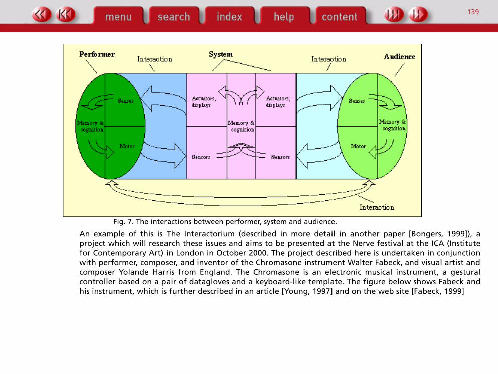
Fig. 7. The interactions between performer, system and audience.
An example of this is The Interactorium (described in more detail in another paper [Bongers, 1999]), aproject which will research these issues and aims to be presented at the Nerve festival at the ICA (Institutefor Contemporary Art) in London in October 2000. The project described here is undertaken in conjunctionwith performer, composer, and inventor of the Chromasone instrument Walter Fabeck,
and visual artist andcomposer Yolande Harris from England. The Chromasone is an electronic musical instrument, a gesturalcontroller based on a pair of datagloves and a keyboard-like template. The figure below shows Fabeck andhis instrument, which is further described in an article [Young, 1997] and on the web site [Fabeck, 1999]

140
Fig. 8. The Chromasone (left) and the Interaction Chair (right).
The audience will be experiencing not only sound and visuals, but also tactual experiences through activecushions in their chairs. To provide the audience with ways to directly interact with the system, their chairswill also be equipped with sensors. The picture above shows a prototype of the Interaction Chair, with thecushion and a close up of the pressure sensor.
The actions of the audience will be displayed visually by a data-projector, and the images are interpreted bythe performer. This way of audience participation, including the translation of the images to musicalperformance parameters is under exploration in the project.
Conclusion
In this chapter I have described the interaction between performer and instrument, the interaction betweenan audience and an installation, and mentioned the possibilities of work that combines these twointeractions. The use of electronic media offers many possibilities for new ways of interaction, both inregarding modalities as well as activating parties previously playing a passive role. Further studies areneeded to investigate how an audience experiences the interaction, as well as experimenting with newtechnologies.
The next chapter aims to take this theory to practice by describing sensing technologies.

141
Sensors
Sensors are the sense organs of a machine. Sensors convert physical energy (from the outside world) intoelectricity (into the machine world). There are sensors available for all known physical quantities, includingthe ones humans use and often with a greater range. For instance, ultrasound frequencies (typically 40 kHzused for motion tracking) or lightwaves in the ultraviolet frequency range.
Sensors are available to convert energy quantities like:• kinetic (incl. pressure, torque, inertia);• light;• sound;• temperature;• smell;• humidity;• electricity;• magnetism;• electro-magnetism (radio waves).
Rather than summing up all these sensors categorised by the physical energy they measure, as is common intechnical literature [Sinclair, 1988], [Horowitz & Hill, 1980] this chapter describe sensors based on the wayshumans have to change the state of the world. These so called output modalities (as described earlier) aremainly related to muscle actions, resulting in for instance movement, air flow or sound. In this chapter,sensors are described which can be used to build a device that interfaces between a human and a machine(computer, electronic sound source etc.) illustrated with practical examples of instruments built by theauthor.
The following categorisation can be used, which takes the human output modalities as a starting point (withmusical instruments in mind):
• muscle action (isometric / isotonic);• blowing;• voice;• other: bio-electricity, temperature, blood pressure, heart rate, etc.
142
Blowing air and outputting sound by the voice are strictly speaking also the result of muscle action, butthere are reasons for describing them separately. The "other" category contains changes in the state of thebody, some of which are not under voluntary control but they can be very interesting. At the moment, in thischapter only the first category is described.
Muscle Action
Forces exist in two forms: dynamic and static e.g., movement and pressure (isometric force). This can haveseveral degrees-of-freedom, referring to the position and orientation of an object in three-dimensionalspace.
Movements can be measured without contact (for instance with a camera) or with a mechanical linkage(with a potmeter for instance). A complex, multiple degree-of-freedom movement (as most movements are!)is often decomposed and limited by mechanical constructions.
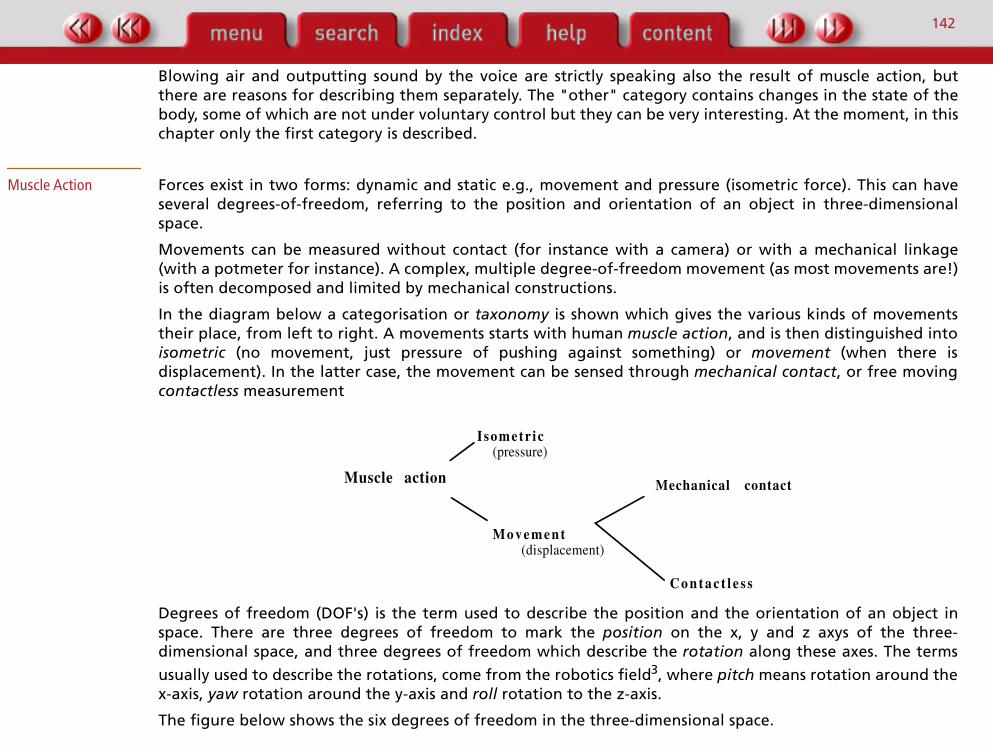
In the diagram below a categorisation or
taxonomy
is shown which gives the various kinds of movementstheir place, from left to right. A movements starts with human
muscle action
, and is then distinguished into
isometric
(no movement, just pressure of pushing against something) or
movement
(when there isdisplacement). In the latter case, the movement can be sensed through
mechanical contact
, or free moving
contactless
measurement
Degrees of freedom (DOF's) is the term used to describe the position and the orientation of an object inspace. There are three degrees of freedom to mark the
position
on the x, y and z axys of the three-dimensional space, and three degrees of freedom which describe the
rotation
along these axes. The terms
usually used to describe the rotations, come from the robotics field
3
, where
pitch
means rotation around thex-axis,
yaw
rotation around the y-axis and
roll
rotation to the z-axis.
The figure below shows the six degrees of freedom in the three-dimensional space.
I sometr ic
M o v e m e n t
(pressure)
(displacement)
Muscle action Mechanical contact
C o n t a c t l e s s

143
Fig. 9. The six degrees of freedom in the three-dimensional space.
The next sections are organised in such a way that they follow the elements as outlined in the taxonomy,and the movements are further discerned in linear (the DOF's related to position) and rotational (the DOF'srelated to orientation).
3. The terms are also common in avionics.

144
Isometric
Pressure sensors
These sensors measure pressure, for instance of a finger pressing on the sensor when there is no movementinvolved (and therefore called isometric).
A very common pressure sensor is the Interlink sensor, which is based on conductive ink technology. Thepicture below on the left show some of the shapes available, and on the right hand a small size applied onthe Meta-trumpet of Jonathan Impett [Impett, 1994]. They are attached to the front valve, where the lefthand index and middle fingers naturally rest.
Fig. 10. Interlink sensors.
The Interlink sensors are available in many shapes and sizes, also available sensing direction (in 1 or 2dimensions and still including the third -isometric- dimension: pressure in the Z-direction) but these aredescribed under the movement sensors.
Isometric
(pressure)
Muscle action
Movement(displacement)
Mechanical contact
Contactless

145
These pressure sensors were also used in the 'Step' and 'Touch' sensors for the Water Pavilion as shownbelow. The pictures show (from left to right) the sensor frame, the inside with the actual sensor outlined,the final look (a yellow blob sticking out of the wall or floor) and the projection overlay which is influencedby pressing the object.
Fig. 11.
Sensors for the Water Pavilion.
The electrical resistance of the sensors is infinite when no force is applied. When a force of a few grams isapplied (a light touch of the fingertip) the resistance of the sensor starts to drop, from about 1M
Ω
to about5k
Ω
when the full force of 20 kilograms is applied, a good range for hand pressure. For the sensors in theWater Pavilion which measure the full weight of a human body (around 80 kg.) a mechanical linkage wasconstructed with the rubber blocs (visible in the picture that shows the inside) to divert part of the force.
Another manufacturer of pressure sensors is Tekscan who make the FlexiForce sensors [Malacaria, 1998], asshown below.
Fig. 12.
FlexiForce sensors.
A cheap way of building pressure sensors is to use the black foam that is used to ship IC's in. This foamconducts electricity (to avoid static charges) and the resistance changes when compressed. Copper foilattached to both sides can be used to solder the leads to.

146
The part that senses aftertouch in a Yamaha DX7 synthesizer is based on this principle. It is a long and veryflat strip, placed under the keys. It was often used as a touch sensor in electronic instruments, such as TheHands of Michel Waisvisz [1999] and the MIDI conductor [Bongers, 1994]. On these instruments the sensorwas placed under the left hand thumb.
An isometric joystick (such as the little red pimple found on IBM notebook computers, the TrackPoint),measures two rotational degrees of freedom. The Sentograph, as used by Tamas Ungvary and Roel Vertegaalfor musical applications, measures finger pressure applied to it in 3 degrees of freedom [Vertegaal andUngvary, 1995]. It is based on the 2D pressure sensor of Manfred Clynes, which he used for research inhuman emotions [Ungvary and Vertegaal, 2000].
The SpaceOrb is a game controller with a ball slightly smaller than a tennis ball, which measures isometricpressure applied to it in all six degrees of freedom. It's cheaply available and interfaces directly with theserial port of a PC or Macintosh.
Switches
Following the terminology as described above, little button switches can be seen as pressure sensors too butwith two discrete values (on/off) instead of continuous measurement. The picture below, on the left, showssome switches commonly used in instruments.
Fig. 13. Switches (left) and Clavette microtonal keyboard (right).
The picture on the right shows an application in the Clavette microtonal keyboard with 122 switches (eachmapped to a pitch) built in 1994 at Sonology for Harold Fortuin [1999]
147
Movement
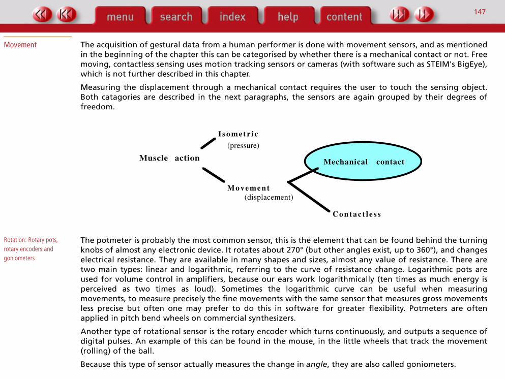
The acquisition of gestural data from a human performer is done with movement sensors, and as mentionedin the beginning of the chapter this can be categorised by whether there is a mechanical contact or not. Freemoving, contactless sensing uses motion tracking sensors or cameras (with software such as STEIM's BigEye),which is not further described in this chapter.
Measuring the displacement through a mechanical contact requires the user to touch the sensing object.Both catagories are described in the next paragraphs, the sensors are again grouped by their degrees offreedom.
Rotation: Rotary pots, rotary encoders and goniometers
The potmeter is probably the most common sensor, this is the element that can be found behind the turningknobs of almost any electronic device. It rotates about 270° (but other angles exist, up to 360°), and changeselectrical
resistance. They are available in many shapes and sizes, almost any value of resistance. There aretwo main types: linear and logarithmic, referring to the curve of resistance change. Logarithmic pots areused for volume control in amplifiers, because our ears work logarithmically (ten times as much energy isperceived as two times as loud). Sometimes the logarithmic curve can be useful when measuringmovements, to measure precisely the fine movements with the same sensor that measures gross movementsless precise but often one may prefer to do this in software for greater flexibility. Potmeters are oftenapplied in pitch bend wheels on commercial synthesizers.
Another type of rotational sensor is the rotary encoder which turns continuously, and outputs a sequence ofdigital pulses. An example of this can be found in the mouse, in the little wheels that track the movement(rolling) of the ball.
Because this type of sensor actually measures the change in
angle
, they are also called goniometers.
I sometr ic
M o v e m e n t
(pressure)
(displacement)
Muscle action Mechanical contact
C o n t a c t l e s s

148
Rotation: Joysticks
A joystick is a device that, through mechanical linkage, divides a movement into two rotational degrees offreedom which are then tracked by individual potmeters. Usually, when held in the hand as in an aeroplane(or game simulation of that) it measures pitch and roll, but measurement of the rotation around the y-axis(yaw) is also possible.
Because the hands are often already in use when playing an instrument or interacting with a system, themovement of the
feet
can be tracked as well. An example is the 3-DOF foot joystick, which measures threerotational degrees of freedom of foot movement. It was originally built at Sonology for Harold Fortuin[1999], and its movement is shown in the movie below.
Fig. 14. Video excerpt. 3-DOF foot joystick.
In the pivot points potmeters are built in which measure the rotation around each axis. The pedals haveadjustable stoppers to change the range of the movement, adjustable friction, and can be adjusted for footsize.
Linear movement: Slide pots
The slide potentiometer can be found for instance in mixing desks. Travel ranges from a few millimetres tosixteen centimetres for normal commercial types. Like the rotary pots, the sliders are available as linear andlogarithmic types, and various resistance values.

149
Fig. 15. Slide potmeters (left) and a pulling sensor.
In the picture on the left two small slide potmeters are shown. The picture on the right shows a bigger slider,a professional audio fader applied in a mechanical construction to create a pulling sensor. This one wasmeasuring people bouncing on a big trampoline.
An even bigger version of this sensor was used as tension sensors for the Soundnet [Sensorband, 1999],[Bongers, 1998b].The picture on the right below show a picture of the members of Sensorband 'playing' theSoundnet, the picture on the left shows a detail of the sensor which is about 35 centimetres long and has anadjustable force range from 50 to 200 kilos.
150
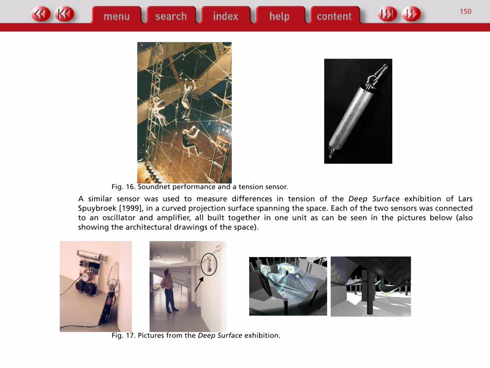
Fig. 16. Soundnet performance and a tension sensor.
A similar sensor was used to measure differences in tension of the Deep Surface exhibition of LarsSpuybroek [1999], in a curved projection surface spanning the space. Each of the two sensors was connectedto an oscillator and amplifier, all built together in one unit as can be seen in the pictures below (alsoshowing the architectural drawings of the space).
Fig. 17. Pictures from the Deep Surface exhibition.

151
Linear movement: pads and ribbons
These are in fact pressure sensors (see above) which sense direction as well, and therefore described here.Trackpads devices as found in laptop computers (invented as a more cost effective and less space consumingalternative for the trackball) are a common example of this.
Two technologies are used to sense the movement of the finger: capacitive and resistive. The trackpad asfound in the Apple PowerBooks is based on capacitive sensing. Under the surface there are two layers offine electrical conductors, arranged in a grid, which create a surface electrical field. Due to the electricalconductivity of the human body, the fingertip distorts the electrical field at that spot, which is detected byscanning the grid. That's why they don't sense the movement of other objects than human.
The touchpad made by Interlink (the VersaPad or OEM parts, [Interlink, 1999]) operates with resistive(semiconductive) technology, and measures the position of a force applied to the surface. It is also touchsensitive (e.g. in the Z direction, isometric), and responds to other objects.
Linear movement: Drawing tablets
Tablets are flat surfaces, ranging in size roughly from A5 to A3. The user can control the cursor by moving aspecial stylus across the surface. Several technologies are used, mostly electromagnetic. Either the tablet orthe pen operates as a transmitter coil, the signal being picked up by the receiver coil. In the older types, thepen was connected to the system with a wire but modern versions are untethered. Wacom for instance usestransponder technology: the pad transmits a (electromagnetic) pulse, forcing the pen to respond with asignal yielding the pen's position. The keys on the pencil are read in the same way (it changes thecharacteristics of the coil, which can be detected), as well as the orientation of the pen: holding it upsidedown activates an eraser mode. It is touch sensitive, and even the angle under which the stylus is held isdetected (on two axes). Because of all these degrees of freedom this is a very sensitive tool for drawingartists. A good description of the technology can be found in an article in Byte [Ward and Schultz, 1993]
The musical application of tablets is described in a paper by Matt Wright [1997] [Editors’ note: see the articleby Dudas and Serafin in this volume].
Rotational: Bending Bend sensors are useful to measure the bending (or abduction) of fingers. This is tracking the rotationalmovement of the joints of the fingers.
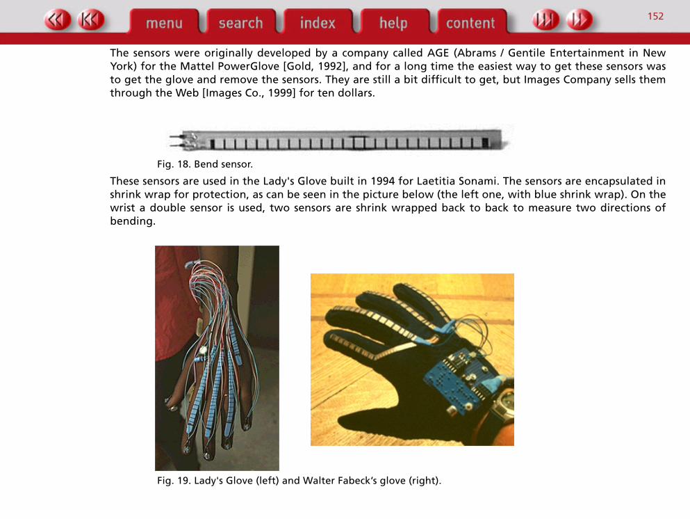
The most used bending sensor is the one in the picture below, also called the flex sensor. It's a flexible stripof plastic with conductive ink technology which changes resistance when bent (from 10 k when flat to 40 kwhen bent at 90°).
152
The sensors were originally developed by a company called AGE (Abrams / Gentile Entertainment in NewYork) for the Mattel PowerGlove [Gold, 1992], and for a long time the easiest way to get these sensors wasto get the glove and remove the sensors. They are still a bit difficult to get, but Images Company sells themthrough the Web [Images Co., 1999] for ten dollars.
Fig. 18. Bend sensor.
These sensors are used in the Lady's Glove built in 1994 for Laetitia Sonami. The sensors are encapsulated inshrink wrap for protection, as can be seen in the picture below (the left one, with blue shrink wrap). On thewrist a double sensor is used, two sensors are shrink wrapped back to back to measure two directions ofbending.
Fig. 19. Lady's Glove (left) and Walter Fabeck’s glove (right).

153
The glove originally built for Walter Fabeck at Sonology has the sensors sewn straight onto the outside of aglove, in such a way that the sensors can slide when the fingers bend. The gloves used are actually golfgloves (summer play) which appear very suitable for this purpose. The picture above on the right shows theglove with the sensors.
For the Laser Bass instrument for Florentijn Boddendijk at Sonology, this sensor was used to measure thebending of the middle finger, sliding through brass rings.
Fig. 20. Bend sensor for the Laser Bass, and glove built for Wart Wamsteker.
Pressure sensors, such as the Interlink sensors described earlier, can also be used as bend sensor becausebending the material results in an increase of pressure in the sensitive area. The glove built for WartWamsteker at Sonology, to replace his worn out customised PowerGlove after about three years of intenseusage, uses long strips of Interlink pressure sensors. In this case, the winter play model of the golf glove wasused because the sensors slide conveniently between the outer fabric and thermally insulating inner part.The picture above on the right shows this glove.
Another way of sensing bending is to use optical fibre, which degrades the amount of light that it letsthrough when the fibre is bent. This can be measured and is then related to the amount of bending. Theoriginal Dataglove by VPL [Zimmerman et al, 1987], [Foley 1987] uses this technique, but the disadvantage isthat it can be quite expensive. The technique works best with low quality fibre like the plastic ones, or fibreswhich have specially for this purpose damaged cladding.

154
Contactless measurement A popular and cheap method of motion tracking is with ultrasonic sound (above the range of humanhearing, i.e. > 20 kHz, typically 40 kHz). The system transmits an ultrasonic sound burst through anultrasonic transducer (the speaker), usually a pulse train of about 10 square waves, and measures the timeelapsed until the burst is received by another ultrasound transducer (the microphone). The delay time isproportional with the distance, this method is therefore known as time-of-flight tracking. The ultrasoundsystem of the Mattel PowerGlove works this way, an L-shaped strip containing the receivers is put aroundthe monitor and with the two transmitters on the glove the system is able to measure position in 3D spaceand rotation around the z-axis (roll) [Gold, 1992].
The picture below shows some of the ultrasound transducers, most of them are manufactured by Murata.
Fig. 21. Some examples of ultrasound transducers.
This technique is also used in gloves and The Hands, where the distance between the hands is measured byhaving the transmitter in one hand and the receiver in the other. The STEIM SensorLab [Cost, 1992] has built-in circuitry and software to use this technology on three separate channels, and needs only one (simple)circuit on the receiver side. The Sonology MicroLab [van den Broek, 1999] has one channel of ultrasounddistance measurement built in, without the need of additional hardware.
I sometr ic
M o v e m e n t
(pressure)
(displacement)
Muscle action Mechanical contact
C o n t a c t l e s s

155
The pictures below show the right hand (rings with the transmitter) and the left hand (with the receiver) ofa smaller version of the Hands built at Sonology in 1993 for Stefan Bezoen.
Fig. 22. The left and right hands parts of the MiniHands.
It is also possible to detect reflection of the sound, the well known Polaroid cameras operate on thisprinciple. This may be less accurate because it is dependent on the reflective properties of the surface, butthe detected object can be passive and therefore doesn't need a wired connection to the system. Thepolaroid transducer (in fact a speaker and microphone in one) works on an electrostatic principle as opposedto piezo and can operate on different frequencies (typ. 200 kHz).
Another way of achieving a wireless link is by transmitting a trigger pulse (which has to be synchronous)from the system via a radio signal or infrared link. The latter method is used to track movements of dancersin the DanceWeb installation [Camurri, 1996]. The transmitter and receiver need a line of sight connection,both the ultrasound and the infrared signals, which can be a disadvantage on the stage.
The Israelian company Pegasus manufactures a very cheap ultrasonic tracking system, called the FreeDsystem (formerly known as the Owl) [Pegasus, 1999]. The tiny transmitter unit can be worn on the finger andincludes also two buttons. It is wireless, the switches emit infrared (RC5-like) signals and the ultrasoundspeaker is continuously emitting pulses. The pulses are picked up by three receivers in an L-shaped unit thatfits on the computer monitor, and by two ASIC chips the signal processing and triangulation calculations aredone in order to measure the position in 3D space. The working area is up to 90 cm, and the accuracy is 0,2mm. It connects to the serial port of a PC, and costs about $80.
All these ultrasound systems remain crude compared to the sonar system of the average bat, however [Suga,1990]. Bats emit ('shout') both constant frequencies and FM modulated frequencies, and by analysing theechoes in a special developed part of their auditory cortex they can detect position, angle and speed (byDoppler shifts) of objects. Future improvements in machine ultrasound tracking may therefore be expected.
156
Linear: magnetic field sensors
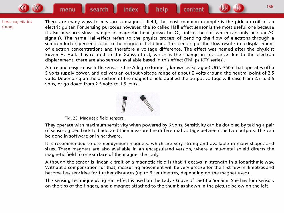
There are many ways to measure a magnetic field, the most common example is the pick up coil of anelectric guitar. For sensing purposes however, the so called Hall effect sensor is the most useful one becauseit also measures slow changes in magnetic field (down to DC, unlike the coil which can only pick up ACsignals). The name Hall-effect refers to the physics process of bending the flow of electrons through asemiconductor, perpendicular to the magnetic field lines. This bending of the flow results in a displacementof electron concentrations and therefore a voltage difference. The effect was named after the physicistEdwin H. Hall. It is related to the Gauss effect, which is the change in resistance due to the electrondisplacement, there are also sensors available based in this effect (Philips KTY series).
A nice and easy to use little sensor is the Allegro (formerly known as Sprague) UGN-3505 that operates off a5 volts supply power, and delivers an output voltage range of about 2 volts around the neutral point of 2.5volts. Depending on the direction of the magnetic field applied the output voltage will raise from 2.5 to 3.5volts, or go down from 2.5 volts to 1.5 volts.
Fig. 23. Magnetic field sensors.
They operate with maximum sensitivity when powered by 6 volts. Sensitivity can be doubled by taking a pairof sensors glued back to back, and then measure the differential voltage between the two outputs. This canbe done in software or in hardware.
It is recommended to use neodymium magnets, which are very strong and available in many shapes andsizes. These magnets are also available in an encapsulated version, where a mu-metal shield directs themagnetic field to one surface of the magnet disc only.
Although the sensor is linear, a trait of a magnetic field is that it decays in strength in a logarithmic way.Without a compensation for that, measuring movement will be very precise for the first few millimetres andbecome less sensitive for further distances (up to 6 centimetres, depending on the magnet used).
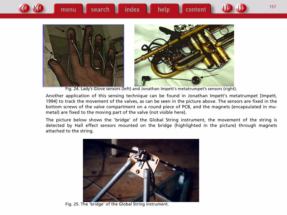
This sensing technique using Hall effect is used on the Lady's Glove of Laetitia Sonami. She has four sensorson the tips of the fingers, and a magnet attached to the thumb as shown in the picture below on the left.
157
Fig. 24. Lady’s Glove sensors (left) and Jonathan Impett's metatrumpet’s sensors (right).
Another application of this sensing technique can be found in Jonathan Impett's metatrumpet [Impett,1994] to track the movement of the valves, as can be seen in the picture above. The sensors are fixed in thebottom screws of the valve compartment on a round piece of PCB, and the magnets (encapsulated in mu-metal) are fixed to the moving part of the valve (not visible here).
The picture below shows the 'bridge' of the Global String instrument, the movement of the string isdetected by Hall effect sensors mounted on the bridge (highlighted in the picture) through magnetsattached to the string.
Fig. 25. The 'bridge' of the Global String instrument.

158
The picture below shows the pulling sensors used in The Web instrument devised by Michel Waisvisz[Krefeld, 1990] and built at Sonology in 1990. The change in string tension results in a movement of themagnet attached to the end of the string, which is sensed by the fixed Hall-effect sensor. Due to thelogarithmic signal of the sensor, it was very hard to get a linear reading out of this set up.
Fig. 26. Pulling sensors used in The Web.
Rotation: mercury tilt switches
Tilt or inclination sensors are very useful for measuring orientation of (parts of) the body. The mostcommonly used ones are glass mercury switches, and use gravity to move a little blob of mercury. Mercuryswitches are often designed to work with higher voltages, but some ones have special contacts so theyoperate well with the 5 volt range. The movie below shows how the mercury closes the contact by themovement of the sensor.
Fig. 27. Video excerpt. Mercury tilt switch.
The ones used in The Hands are made by the German manufacturer Günther. By using four sensors intriangular setting (as a pyramid shape) 10 different inclinations can be measured: one neutral position withall the switches closed, four orientations of roll and pitch, clockwise and anticlockwise rotation, and fourintermediate stages, and one more when the hands are turned upside down when all switches are open.
Piston
Neodymium magnetMumetal shield
Hall-effect sensor
SpringBolt String
159
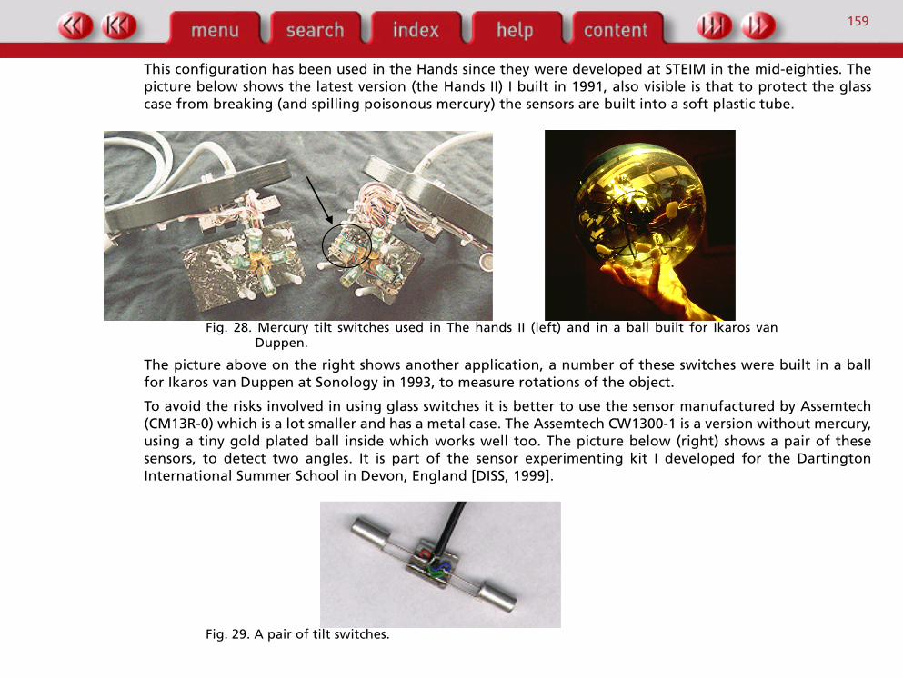
This configuration has been used in the Hands since they were developed at STEIM in the mid-eighties. Thepicture below shows the latest version (the Hands II) I built in 1991, also visible is that to protect the glasscase from breaking (and spilling poisonous mercury) the sensors are built into a soft plastic tube.
Fig. 28. Mercury tilt switches used in The hands II (left) and in a ball built for Ikaros vanDuppen.
The picture above on the right shows another application, a number of these switches were built in a ballfor Ikaros van Duppen at Sonology in 1993, to measure rotations of the object.
To avoid the risks involved in using glass switches it is better to use the sensor manufactured by Assemtech(CM13R-0) which is a lot smaller and has a metal case. The Assemtech CW1300-1 is a version without mercury,using a tiny gold plated ball inside which works well too. The picture below (right) shows a pair of thesesensors, to detect two angles. It is part of the sensor experimenting kit I developed for the DartingtonInternational Summer School in Devon, England [DISS, 1999].
Fig. 29. A pair of tilt switches.
160
Assemtech makes a variety of sensors like this which can also be used as shock detector, as found in pinballmachines (hence the phrase "op tilt slaan" in Dutch) and car alarms.
Inclination sensors also exist in continuous versions (as opposed to the switch action described here), butthese are quite expensive and not very suitable for tracking swift movements. They operate with a smallamount of special fluid in a cavity, the movement of which results in a change of the electric capacity.
Linear: accelerometers Accelerometers measure acceleration (and deceleration, often a far richer source of information). Mostsensors of this type are quite expensive, due to the high precision required in a common application forposition detection (extracted from the direction and amount of acceleration over time measured) for carand avionics navigation systems. Nowadays another common application is shock detection in airbag systemsin cars, and cheaper sensors are becoming available. They are little IC's (Integrated Circuits) that have amicroscopic sized mass etched out of the silicon, which is suspended in little pieces of silicon that act aspiezo-resistive sensors. An acceleration of the chip results in a relative movement of the little mass due toinertia, leading to a little change in voltage on the output.
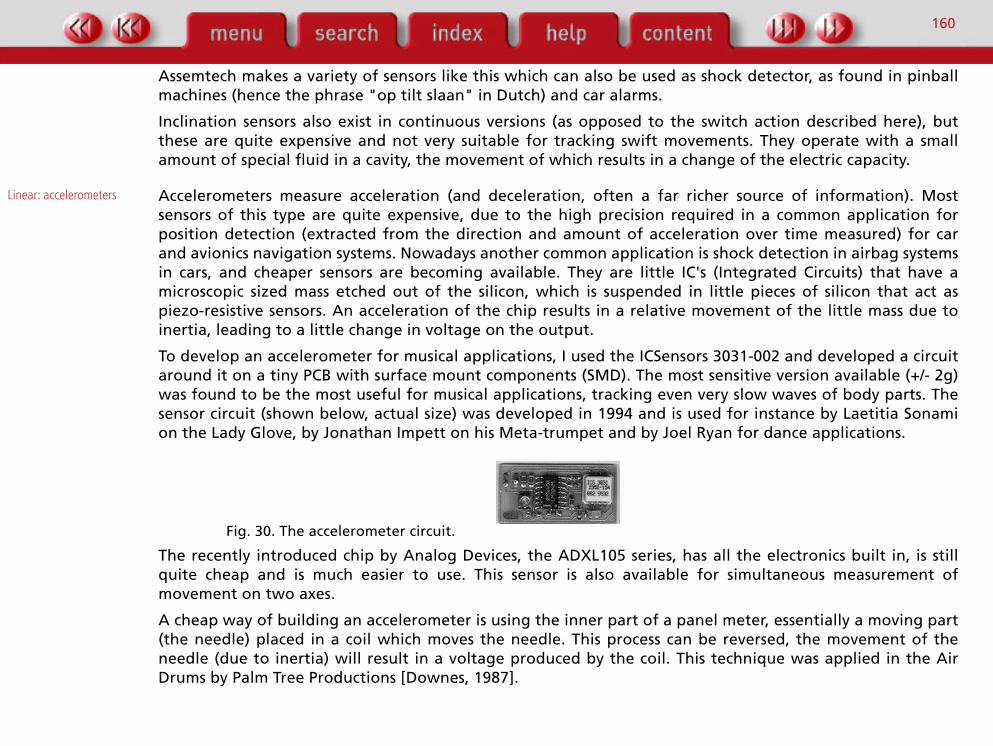
To develop an accelerometer for musical applications, I used the ICSensors 3031-002 and developed a circuitaround it on a tiny PCB with surface mount components (SMD). The most sensitive version available (+/- 2g)was found to be the most useful for musical applications, tracking even very slow waves of body parts. Thesensor circuit (shown below, actual size) was developed in 1994 and is used for instance by Laetitia Sonamion the Lady Glove, by Jonathan Impett on his Meta-trumpet and by Joel Ryan for dance applications.
Fig. 30. The accelerometer circuit.
The recently introduced chip by Analog Devices, the ADXL105 series, has all the electronics built in, is stillquite cheap and is much easier to use. This sensor is also available for simultaneous measurement ofmovement on two axes.
A cheap way of building an accelerometer is using the inner part of a panel meter, essentially a moving part(the needle) placed in a coil which moves the needle. This process can be reversed, the movement of theneedle (due to inertia) will result in a voltage produced by the coil. This technique was applied in the AirDrums by Palm Tree Productions [Downes, 1987].
161
Rotational: gyroscopes The gyroscope effect can be used for orientation sensing as well. Planes use gyroscopes to fly straight,mechanical devices that are very expensive again but these days cheap semiconductor versions appear aswell. An example is the Murata ENC05E (or the ENC-05S), a little chip that outputs a voltage swing of a fewvolts proportional with the angular (rotational) velocity of the device. It operates on the principle of avibrating triangular element, micromachined in silicon in the same way as the accelerometers, and the (tiny)forces operating on the suspension of the vibrating element when the object is turned (due to inertia) aretranslated into a voltage.
Linear: Photocells Photocells are often found in every day life, for instance to detect people being caught between elevatordoors. They operate by sending out a beam of light (often infrared) and detecting the obstruction of thelight path, or reflection of the light. Operating distances vary from centimetres to tens of meters, andindustrial rugged types are available. There are three types commonly available:
• A pair of one transmitter and one receiver • One unit which is both transmitter and receiver, and detects the light path from a (passive)
reflector• One unit which is both transmitter and receiver, and detects the proximity of an object by the
reflection off that object.
In the Water Pavilion interactive building the position of the audience was sensed with the latter type, ofindustrial water proof quality.
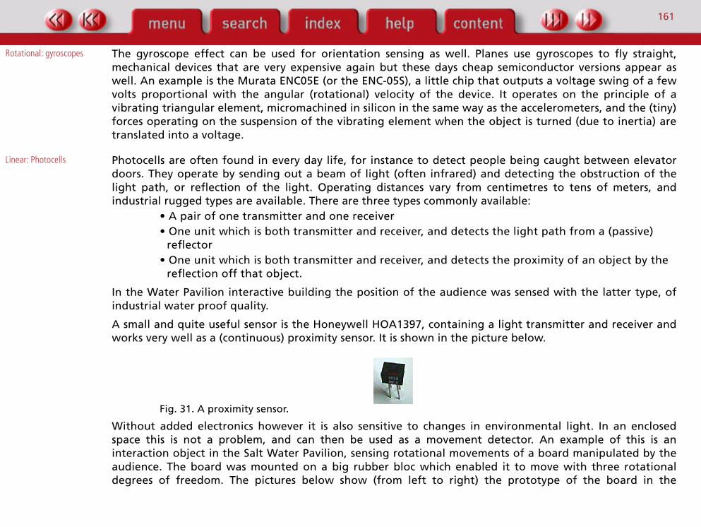
A small and quite useful sensor is the Honeywell HOA1397, containing a light transmitter and receiver andworks very well as a (continuous) proximity sensor. It is shown in the picture below.
Fig. 31. A proximity sensor.
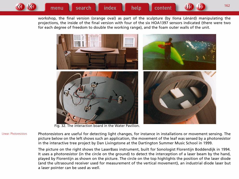
Without added electronics however it is also sensitive to changes in environmental light. In an enclosedspace this is not a problem, and can then be used as a movement detector. An example of this is aninteraction object in the Salt Water Pavilion, sensing rotational movements of a board manipulated by theaudience. The board was mounted on a big rubber bloc which enabled it to move with three rotationaldegrees of freedom. The pictures below show (from left to right) the prototype of the board in the
162
workshop, the final version (orange oval) as part of the sculpture (by Ilona Lénárd) manipulating theprojections, the inside of the final version with four of the six HOA1397 sensors indicated (there were twofor each degree of freedom to double the working range), and the foam outer walls of the unit.
Fig. 32. The interaction board in the Water Pavilion.
Linear: Photoresistors Photoresistors are useful for detecting light changes, for instance in installations or movement sensing. Thepicture below on the left shows such an application, the movement of the leaf was sensed by a photoresistorin the interactive tree project by Dan Livingstone at the Dartington Summer Music School in 1999.
The picture on the right shows the LaserBass instrument, built for Sonologist Florentijn Boddendijk in 1994.It uses a photoresistor (in the circle on the ground) to detect the interception of a laser beam by the hand,played by Florentijn as shown on the picture. The circle on the top highlights the position of the laser diode(and the ultrasound receiver used for measurement of the vertical movement), an industrial diode laser buta laser pointer can be used as well.

163
Fig. 33. Florentijn Boddendijk playing the LaserBass (left), and a leaf being sensed.
Conclusion
With the work described in this paper, it is hoped that ideas for new instruments, installations andinteractions in electronic arts are evoked. With the practical information supplied it is possible to build atleast protoytpes to try out ideas, even for people without a background in electrical engineering. Most ofthe techniques and sensor parts are cheaply available and easy to use.
In the Interactive Electronic Music workshops at the Dartington Summer School in Devon, Englandparticipants unanimously agreed that being able to build their own instruments, from soldering to softwareprogramming, improved their understanding of the idiom.
As I mentioned in the introduction, this paper is a work in progress and I do intend to keep updating andexpanding it. I therefore welcome all suggestions and comments, including severe criticism! The taxonomyor categorisation of sensors as presented in the beginning of the previous chapter is intended as aframework to fill in with knowledge acquired.
164
Acknowledgements
Most of the musical instruments developed and build at the Institute for Sonology at the Royal Conservatoryin the Hague were the result of a team effort. This includes all the students and guests I mentionedthroughout this paper who came in with their ideas, and my colleagues at the electronic workshop JosDiergaarde and Jo Scherpenisse – who has been around in electronic music long enough to develop anability to see electrons. I want to thank Jo also, as well as my successor at Sonology Lex van den Broek, forkeeping me updated about recent developments and for their useful comments on earlier drafts of thiswriting. I (still) regard Paul Berg as my mentor in this field, and thank him again for the help with this paper.
I could never have build the instruments developed at or commissioned by STEIM in Amsterdam withoutMichel Waisvisz' vision and seminal ideas, the electronic skills of Peter Cost (in the early years) and thesoftware developed by Frank Baldé and Tom Demeyer.
In the countless projects that involved mechanical engineering, a lot of work was done by Theo Borsboomwho diverted his attention from (re-)building Harley Davidsons to reading my mind in order to create formsin aluminium and stainless steel from his lathe and milling machine. When the work involved welding, wewere often helped by John Pauli, another Harley mechanic.
I want to thank Janwillem Schrofer, Director of the Rijksakademie in Amsterdam, for commissioning asubstantial part of the writing of this paper.
The participants of the Dartington Summer School who did the course in interactive electronic music in thelast two years served as willing guinea pigs for the soldering and tinkering as suggested in this paper.
The photographs and illustrations in this paper are all made by me, except for the picture of Laetitia Sonamiand her glove in chapter 2 (by André Hoekzema), the picture of Michel Waisvisz and his Hands (by Carla vanThijn), and the pictures of the projections in the Water Pavilion (by Lars Spuybroek and Kas Oosterhuis).
I want to thank the editors of this book, Marcelo Wanderley and Marc Battier, for supporting andencouraging me to write this paper.

165
References
[Bongers, 1994] Bongers, Bert. 1994. "The Use of Active Tactile and Force Feedback in Timbre Controlling MusicalInstruments". In Proceedings of the International Computer Music Conference, San Francisco: InternationalComputer Music Association, pp. 171-174.
[Bongers, 1998a] ———, J.H. Eggen, D.V. Keyson and S.C. Pauws. 1998. "Multimodal Interaction Styles." HCI Letters 1(1): 3-5.
[Bongers, 1998b] ———. 1998. "An Interview with Sensorband." Computer Music Journal 22(1), 1998, pp. 13-24 On line athttp://mitpress.mit.edu/journals/COMJ/sample-article.html.
[Bongers, 1998c] ———. 1998. "Tactual display of sound properties in electronic musical instruments." Displays Journal 18(3):129-133.
[Bongers, 1999] ———. 1999. "Exploring Novel Ways of Interaction in Musical Performance." In Proceedings of the Creativity& Cognition Conference, Loughborough, UK, 11 – 13 October 1999, pp. 76 - 81.
[van den Broek, 1999] Broek, Lex van den. 1999. MicroLab Manual. The Hague, The Netherlands: Royal Conservatory.
[Camurri, 1996] Camurri, Antonio. 1996. "Multimodal Environments." In ISEA 1996 Book of Abstracts, p14.
[Chadabe, 1997] Chadabe, Joel. 1997. Electric Sound, the Past and Promise of Electronic Music. Prentice Hall, NJ.
[Cost, 1992] Cost, Peter.1992. SensorLab Rev.C Hardware Manual. Amsterdam: STEIM Foundation.
[DISS, 1999] Dartington International Summer School. Web site: http://www.dissorg.u-net.com/.
[Downes, 1987] Downes, Pat. 1987. "Motion Sensing in Music and Dance Performance." In Proceedings of the AES 5thInternational Conference, pp. 165 - 171.
[Fabeck, 1999] Fabeck, Walter. 1999. Web site describing the Chromasone; http://www.chrom.demon.co.uk/.
[Foley, 1987] Foley, James D. 1987. "Interfaces for Advanced Computing." Scientific American, October, pp. 82-90.
[Fortuin, 1999] Fortuin, Harold. 1999. The Clavette. Web site: http://www.wavefront.com/~hfortuin/clavett.htm.

166
[Gold, 1992] Gold, Rich. 1999. "It's Play Time." In CyberArts, Exploring Art and Technology, Linda Jacobson, ed. New York:Miller Freeman, pp.196-202.
[Horowitz & Hill, 1980] Horowitz, Paul and Winfield Hill. 1980. The Art of Electronics, Cambridge University Press, 1980.
[Impett, 1994a] Impett, Jonathan. 1994. A Meta-Trumpet(er). In Proceedings of the International Computer MusicConference, San Francisco: International Computer Music Association, pp 147 - 150.
[Impett, 1994b] ———. 1994. Mirror-Rite. On Ladder of Escape nr. 7 CD. Amsterdam: Attacca Records.
[Impett, 1996] ———. 1996. "Projection and Interactivity of Musical Structures in Mirror-Rite." Organised Sound, 1(3): 203 –211.
[Interlink, 1999] Interlink Electronics. 1999. Website: www.interlinkelec.com.
[de Jong, 1991] Jong, Jacqueline B. de (ed.). 1991. Addenda & Errata, the OOC Ockham Coffee-Table Book. Researchprogram Support, Survival and Culture, University of Amsterdam, Amsterdam: Thesis Publishers.
[Kalawaky, 1993] Kalawsky, Roy S. 1993. The Science of Virtual Reality and Virtual Environments. Addison-Wesley.
[Krefeld, 1990] Krefeld, Volker. 1990. "The Hand in The Web: An Interview with Michel Waisvisz." Computer Music Journal,14(2): 28-33.
[Loomis and Leederman, 1986]
Loomis, J. M. and S. J. Leederman. 1986. "Tactual Perception." Handbook of Perception and HumanPerformance, chap. 31.
[Lusted and Knapp 1996] Lusted, H. S. and R. B. Knapp. 1996. "Controlling Computers with Neural Signals." Scientific American,October, pp. 58 - 63.
[Malacaria, 1998] Malacaria, Charles F. 1998. "A Thin, Flexible, Matrix-Based Pressure Sensor." Sensors Magazine, September1998. On line at http://www.sensorsmag.com/articles/0998/thi0998/index.htm.
[Martin, 1995] Martin, Steven. 1995. Theremin. An Electronic Odyssey, Los Angeles: Orion Home Video 5080, 84 minutes.
[Misch, 1997] Misch, Georg. 1997. "The Trautonium, the Difference Engine." The Wire Magazine, September, pp. 42- 46.

167
[Moog and Rhea, 1990] Moog, Robert A. and Thomas L. Rhea. 1990. "Evolution of the Keyboard Interface: The Bösendorfer 290 SERecording Piano and The Moog Multiply-Touch-Sensitive Keyboards." Computer Music Journal 14(1), pp. 52-60.
[Pegasus, 1999] Pegasus Technologies Ltd. Website: www.pegatech.com.
[Rheingold, 1992] Rheingold, Howard. 1992. Virtual Reality. London: Manderin Paperbacks.
[Robinett, 1992] Robinett, Warren. 1992. "Synthetic Experience: A Proposed Taxonomy." Presence, 1(2): 229 – 247.
[Ruschkowski, 1990] Ruschkowski, André. 1990. Soundscapes, Elektronische Klangerzeugung und Musik. Lied der ZeitMusikverlag Berlin.
[Schomaker et al, 1995] Schomaker, Lambert, Stefan Münch and K. Hartung, eds. 1995. A Taxonomy of Multimodal Interaction in theHuman Information Processing System. Report of the ESPRIT project 8579: MIAMI.
[Schwartz, 1997] Schwatz, Ineke. 1997. "A Testing Ground for Interactivity: The Water Pavilions by Lars Spuybroek and KasOosterhuis", Archis, September, pp. 9-13.
[Sensorband, 1999] Sensorband. Web site: http://www.sensorband.com.
[Sinclair, 1988] Sinclair, I. R. 1988. Sensors and transducers. England: Blackwell Scientific Publications.
[Suga, 1990] Suga, Nobuo. 1990. "Biosonar and Neural Computation in Bats." Scientific American, June, pp. 34-41.
[Spuybroek, 1999] Spuybroek, Lars. 1999. Deep Surface. Publication, Rotterdam.
[Steinglass, 1999] Steinglass, Matt. 1999. "Interface Off." Metropolis Magazine, June 1999. on line at: http://www.metropolismag.com/new/content/tech/ju99inte.htm.
[Tanaka, 1993] Tanaka, Atau. 1993. "Musical Technical Issues in Using Interactive Instrument Technology with Application tothe BioMuse." In Proceedings of the International Computer Music Conference, San Francisco: InternationalComputer Music Association, pp. 124-126.
[Tanaka, 1999] ———. 1999. Global String Web site http://www.sensorband.com/atau/globalstring.
168
[Ungvary and Vertegaal, 2000]
Ungvary, Tamas, and Roel Vertegaal. 2000. "Cognition and Physicality in Musical CyberInstruments." In thisvolume.
[Vertegaal and Ungvary, 1995]
Vertegaal, Roel, and Tamas Ungvary. 1995. "The Sentograph: Input Devices and the Communication ofBodily Expression." In Proceedings of the International Computer Music Conference, San Francisco:International Computer Music Association, pp. 253-256.
[Waisvisz, 1985] Waisvisz, Michel. 1985. "The Hands, a set of Remote MIDI-controllers." In Proceedings of the InternationalComputer Music Conference, San Francisco: International Computer Music Association, pp. 313-318.
[Waisvisz, 1999] ———. 1999. Web site: http://www.xs4all.nl/~mwais/.
[Wright et al, 1997] Wright, Matthew, David Wessel and Adrian Freed. 1997. "New Musical Control Structures from StandardGestural Controllers." In Proceedings of the International Computer Music Conference, San Francisco:International Computer Music Association. On line at http://cnmat.CNMAT.Berkeley.EDU/ICMC97/GesturalControl.html.
[Young, 1984] Young, Gayle. 1984. "Hugh le Caine's 1948 Sackbut Synthesizer." In Proceedings of the InternationalComputer Music Conference, San Francisco: International Computer Music Association, pp. 203-212.
[Young, 1997] Young, Rob. 1997. "Meets Walter Fabeck, Inventor of the Chromasone." The Wire, issue 166, December,p 69.
[Zimmerman et al, 1987] Zimmerman, Thomas G., Jaron Lanier, Chuck Blanchard, Steve Bryson and Young Harvill. 1987. "A HandGesture Interface Device." In Proceedings of the Human Factors in Computing Systems and GraphicsInterface (CHI+GI), Toronto, pp. 189-192.
[Zimmerman et al, 1995] ———, Joshua R. Smith, Joseph A. Paradiso, David Allport and Neil Gershenfeld. 1995. "Applying ElectricField Sensing to Human-Computer Interfaces." In Proceedings of the CHI'95 conference, Denver, pp. 280-287.