Embed Size (px)
Citation preview
Ramechhap Municipality
Office Of Municipal Executive
Ramechhap Bazzar,Ramechhap
Province No.3
"EXPRESSION OF INTEREST"
For
"Detailed Engineering Survey, Design cost estimate and tender document of Ramechhap Municipality Ring road
(for New Section to all weather standards) and Preparation of Detailed Project Report (DPR), Contract
Documents"
Ramechhap Municipality
Office Of Municipal Executive
Ramechhap Bazzar,Ramechhap
Province No.3
INVITATION FOR EXPRESSIONS OF INTEREST(EOI) FOR SHORT–LISTING OF CONSULTANTS
First Date Of Publication-2075-10-01
1. Ramechhap Municipality invites separate application from the Consulting firms which wishes to be short listed for following jobs. Notice can be downloaded from our website www.ramechhapmun.gov.np.
2. Interested eligible Firms may obtain Further information from Ramechhap Municipality Procurement unit (Phone 048-400116,9863023015)during office Hour on or before 15th day.
3. The Short Listing document may be collected free of cost from Ramechhap Municipality, Procurement Unit by the interested firms on the submission of written application by attaching the following certified document to prove that company fulfills all required eligibility criteria outlined below on or before 15th day except official holidays.
Company Registration
Tax clearance certificate of FY 074/075
VAT/PAN registration 4. Sealed application must be delivered to Office of Ramechhap Municipality on or before 12:00
hours ,16th day. The Submitted EOI will be opened at 13:00 hours, of the same day in the presence of Ramechhap Municipality Officials and representatives of firms who wish to attend.
5. In case the day of submission of the EOI falls on a public holiday, it shall then be submitted on the following working day. Only the shortlisted Consulting Firms shall be invited for RFP (Request for Proposal). Reserves the right to shortlist any or all of the Firms without assigning and reasons whatsoever. Further information or clarification can be obtained from Municipality office during office hours.
6. The qualified firms shall be informed of the outcome of short listing. Solicitation for the submission of The Technical and Financial Proposal will be published in due course of time.
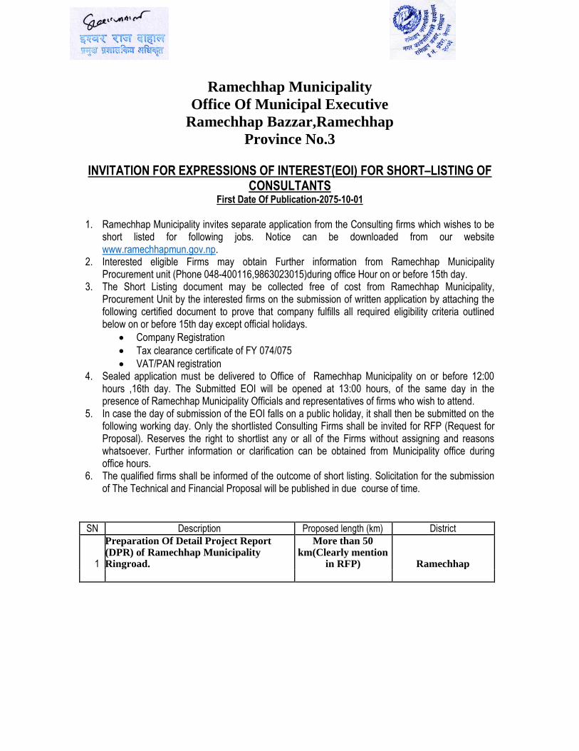
SN Description Proposed length (km) District
1
Preparation Of Detail Project Report (DPR) of Ramechhap Municipality Ringroad.
More than 50 km(Clearly mention
in RFP) Ramechhap
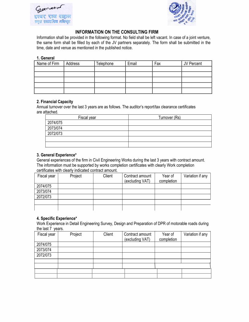
INFORMATION ON THE CONSULTING FIRM Information shall be provided in the following format. No field shall be left vacant. In case of a joint venture, the same form shall be filled by each of the JV partners separately. The form shall be submitted in the time, date and venue as mentioned in the published notice.
1. General
Name of Firm Address Telephone Email Fax JV Percent
2. Financial Capacity Annual turnover over the last 3 years are as follows. The auditor’s report/tax clearance certificates are attached.
Fiscal year Turnover (Rs) 2074/075 2073/074 2072/073
3. General Experience* General experiences of the firm in Civil Engineering Works during the last 3 years with contract amount. The information must be supported by works completion certificates with clearly Work completion certificates with clearly indicated contract amount. Fiscal year Project Client Contract amount Year of Variation if any
(excluding VAT) completion 2074/075 2073/074 2072/073
4. Specific Experience* Work Experience in Detail Engineering Survey, Design and Preparation of DPR of motorable roads during the last 7 years. Fiscal year Project Client Contract amount Year of Variation if any
(excluding VAT) completion 2074/075 2073/074 2072/073
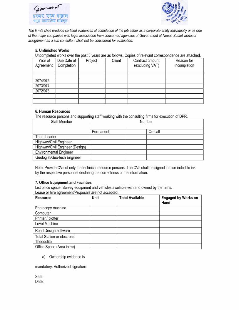
The firm/s shall produce certified evidences of completion of the job either as a corporate entity individually or as one
of the major companies with legal association from concerned agencies of Government of Nepal. Sublet works or
assignment as a sub consultant shall not be considered for evaluation.
5. Unfinished Works
Uncompleted works over the past 3 years are as follows. Copies of relevant correspondence are attached.
Year of Due Date of Project Client Contract amount Reason for Agreement Completion (excluding VAT) Incompletion
2074/075
2073/074
2072/073
6. Human Resources
The resource persons and supporting staff working with the consulting firms for execution of DPR.
Staff Member Number
Permanent On-call
Team Leader
Highway/Civil Engineer
Highway/Civil Engineer (Design)
Environmental Engineer
Geologist/Geo-tech Engineer
Note: Provide CVs of only the technical resource persons. The CVs shall be signed in blue indelible ink by the respective personnel declaring the correctness of the information.
7. Office Equipment and Facilities List office space, Survey equipment and vehicles available with and owned by the firms. Lease or hire agreement/Proposals are not accepted. Resource Unit Total Available Engaged by Works on
Hand Photocopy machine Computer Printer / plotter Level Machine
Road Design software
Total Station or electronic
Theodolite Office Space (Area in m2)
a) Ownership evidence is
mandatory. Authorized signature:
Seal: Date:
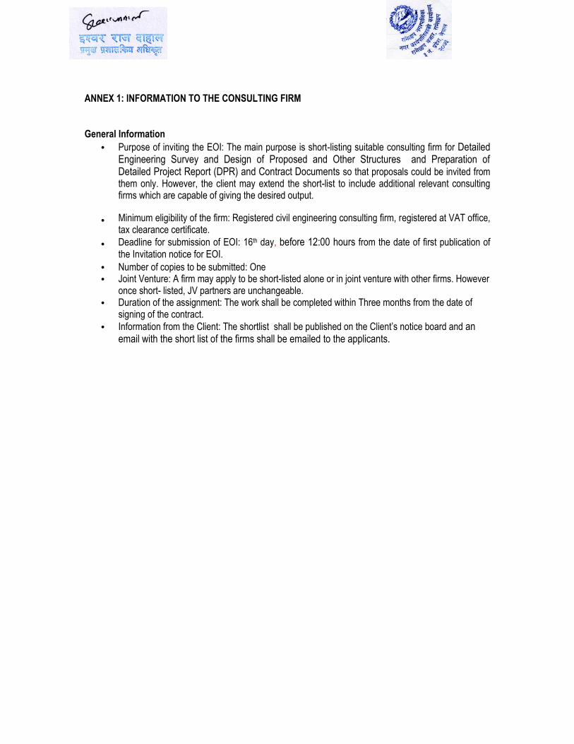
ANNEX 1: INFORMATION TO THE CONSULTING FIRM
General Information
Purpose of inviting the EOI: The main purpose is short-listing suitable consulting firm for Detailed Engineering Survey and Design of Proposed and Other Structures and Preparation of Detailed Project Report (DPR) and Contract Documents so that proposals could be invited from them only. However, the client may extend the short-list to include additional relevant consulting firms which are capable of giving the desired output. Minimum eligibility of the firm: Registered civil engineering consulting firm, registered at VAT office, tax clearance certificate. Deadline for submission of EOI: 16th day, before 12:00 hours from the date of first publication of the Invitation notice for EOI.
Number of copies to be submitted: One Joint Venture: A firm may apply to be short-listed alone or in joint venture with other firms. However once short- listed, JV partners are unchangeable. Duration of the assignment: The work shall be completed within Three months from the date of signing of the contract.
Information from the Client: The shortlist shall be published on the Client’s notice board and an
email with the short list of the firms shall be emailed to the applicants.
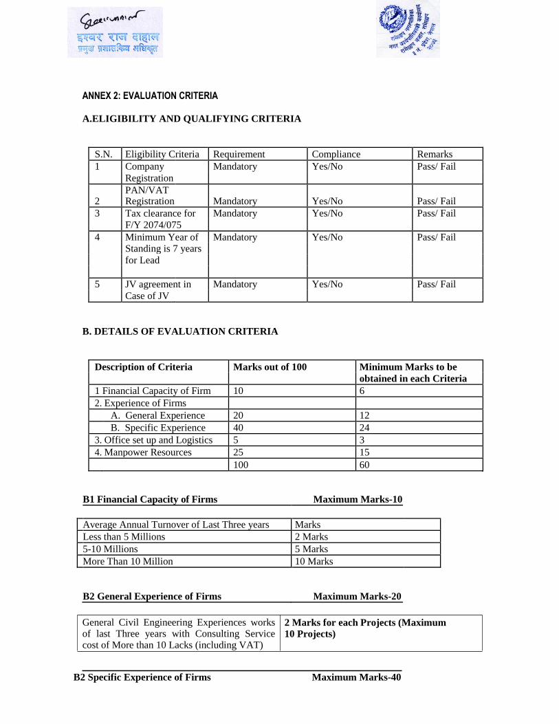
ANNEX 2: EVALUATION CRITERIA
A.ELIGIBILITY AND QUALIFYING CRITERIA
S.N. Eligibility Criteria Requirement Compliance Remarks
1 Company Mandatory Yes/No Pass/ Fail
Registration
2
PAN/VAT Registration Mandatory Yes/No Pass/ Fail
3 Tax clearance for Mandatory Yes/No Pass/ Fail
F/Y 2074/075
4 Minimum Year of Mandatory Yes/No Pass/ Fail Standing is 7 years
for Lead
5 JV agreement in Mandatory Yes/No Pass/ Fail
Case of JV
B. DETAILS OF EVALUATION CRITERIA
Description of Criteria Marks out of 100 Minimum Marks to be
obtained in each Criteria
1 Financial Capacity of Firm 10 6
2. Experience of Firms
A. General Experience 20 12
B. Specific Experience 40 24
3. Office set up and Logistics 5 3
4. Manpower Resources 25 15
100 60
B1 Financial Capacity of Firms Maximum Marks-10
Average Annual Turnover of Last Three years Marks
Less than 5 Millions 2 Marks
5-10 Millions 5 Marks
More Than 10 Million 10 Marks
B2 General Experience of Firms Maximum Marks-20
General Civil Engineering Experiences works of last Three years with Consulting Service cost of More than 10 Lacks (including VAT)
2 Marks for each Projects (Maximum
10 Projects)
B2 Specific Experience of Firms Maximum Marks-40
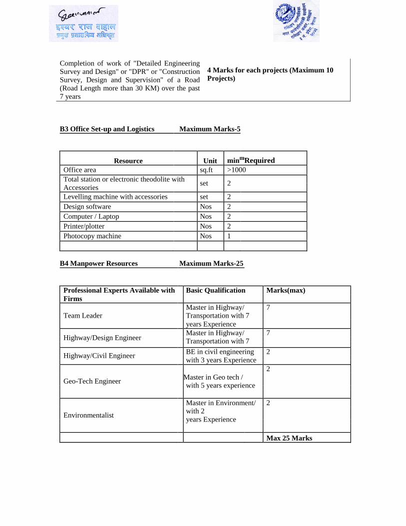
Completion of work of "Detailed Engineering Survey and Design" or "DPR" or "Construction Survey, Design and Supervision" of a Road (Road Length more than 30 KM) over the past 7 years
4 Marks for each projects (Maximum 10
Projects)
B3 Office Set-up and Logistics Maximum Marks-5
Resource Unit minmRequired
Office area sq.ft >1000
Total station or electronic theodolite with set 2
Accessories
Levelling machine with accessories set 2
Design software Nos 2
Computer / Laptop Nos 2
Printer/plotter Nos 2
Photocopy machine Nos 1
B4 Manpower Resources Maximum Marks-25
Professional Experts Available with Basic Qualification Marks(max)
Firms
Master in Highway/ 7
Team Leader Transportation with 7
years Experience
Highway/Design Engineer Master in Highway/ 7
Transportation with 7
Highway/Civil Engineer BE in civil engineering 2
with 3 years Experience
2
Geo-Tech Engineer Master in Geo tech /
with 5 years experience
Master in Environment/ 2
Environmentalist with 2
years Experience
Max 25 Marks
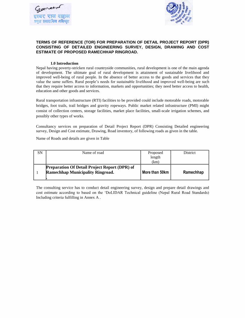
TERMS OF REFERENCE (TOR) FOR PREPARATION OF DETAIL PROJECT REPORT (DPR)
CONSISTING OF DETAILED ENGINEERING SURVEY, DESIGN, DRAWING AND COST
ESTIMATE OF PROPOSED RAMECHHAP RINGROAD.
1.0 Introduction Nepal having poverty-stricken rural countryside communities, rural development is one of the main agenda
of development. The ultimate goal of rural development is attainment of sustainable livelihood and
improved well-being of rural people. In the absence of better access to the goods and services that they
value the same suffers. Rural people’s needs for sustainable livelihood and improved well-being are such
that they require better access to information, markets and opportunities; they need better access to health,
education and other goods and services.
Rural transportation infrastructure (RTI) facilities to be provided could include motorable roads, motorable
bridges, foot trails, trail bridges and gravity ropeways. Public market related infrastructure (PMI) might
consist of collection centers, storage facilities, market place facilities, small-scale irrigation schemes, and
possibly other types of works.
Consultancy services on preparation of Detail Project Report (DPR) Consisting Detailed engineering survey, Design and Cost estimate, Drawing, Road inventory, of following roads as given in the table.
Name of Roads and details are given in Table
SN Name of road Proposed District length
(km)
1
Preparation Of Detail Project Report (DPR) of
Ramechhap Municipality Ringroad. More than 50km Ramechhap
.
The consulting service has to conduct detail engineering survey, design and prepare detail drawings and
cost estimate according to based on the ‘DoLIDAR Technical guideline (Nepal Rural Road Standards)
Including criteria fulfilling in Annex A .
1.1. Objectives
The overall objective of the consulting services is to prepare conduct detailed engineering survey, design
and prepare detailed drawings and cost estimate of above proposed road of the municipality. The consultant
should follow the DoLIDAR’s Norms, Specifications and design standard.
The specific objectives, but not necessarily limited to the following, are: Analyze the existing situation on topographic map as well as on field.
Conduct detailed engineering survey of the alignment and its corridor.
Conduct hydrological studies for cross drainage works and fixing of embankment height.
Design the road details.
Prepare working drawings.
Prepare cost estimate with analysis of rates.
Prepare survey and design reports.
Prepare the contract Documents (bid document, Technical Specification, Design Drawing etc.)
1.2. Scope of Services
The consulting service is to provide high quality professional services for detail engineering survey, design
and prepare detail drawings and cost estimate according to the ‘DoLIDAR Technical guideline (Nepal
Rural Road Standards) on Planning and DoLIDARs design standard, Design and Construction of Rural
Roads’. The consultant shall carry out the necessary field works along the alignment. The team personnel
to be mobilized for field visit and schedule of field tasks should be prepared and should be included in the
proposal. The center line should be set out with proper establishment of bench marks, as far as possible
following the existing trail or alignment. The consultant shall then carry out further survey works necessary
for detailed design of the road. The consultant shall be responsible for the analysis and interpretation of the
data. The scope of services to be carried out by the Consultant shall broadly include, but not be limited to,
the following:
1.2.1. Engineering Details (Field Survey)
The horizontal alignment of the road (i.e. centre line) should be determined within the survey strip of proposed corridor of the optimum alignment between control points specified as a result of the engineering investigation.
Accurate traverse line shall be run along the route selected. In case of improvement of existing road, efforts should be made to adjust the alignment so as to
match the existing road track wherever possible. Strip of sufficient width (10m on either side) to accommodate cut/fill and for possible shift in the
centre line at the final design shall be surveyed. Traverse survey shall be done by Total station/ Theodolite with angles using double reversed
method. Appropriate and accurate method shall be adopted for the distance measurement between two
consecutive transit stations.
Transit stations shall be pegged and numbered following a sequential order. Features like buildings, monuments, cremation center and graveyards, temples, power and
telephone lines, pipelines, existing roads and trails shall be located by offset measurements from the traverse line.
Cross section shall be taken at 10-15m interval and at closer intervals in places having abrupt slope changes or different soil type.
Classification of soil in chainage wise is absolutely necessary. Benchmarks shall be fixed at every 250 m intervals or at 500 m intervals in special cases.
Benchmarks shall also be fixed at bridge and culvert sites. Check all levels with the levels of established Benchmarks by fly leveling for accuracy.
Single datum preferably geodetic survey datum shall be used to tie up all levels. Grid survey at 1 or 2 m intervals may be necessary at places of sharp curves of difficult places and
at all bridge sites.
Data information should be taken on all gullies, depressions, streams and rivers where cross drainage structures are required.
Every retaining structures, breast structures, drainage structures, slope protection measures should be supported by justification and photographs.
Road Inventory with details such as: existing retaining walls, check dams, chutes, pipe and slab culverts, causeways, drain, rehabilitation of existing cannel works and other structures and the consultant shall produce road inventory drawings as per DoLIDAR or other appropriate formats
1.2.2. Environmental Consideration
The basic intention of environmental consideration is to develop the best possible rural road in the given
environmental settings. Environmental consideration basically addresses two aspects: risks or threats,
which are the likely damages to the environmental quality, services and natural wealth; and opportunity or
potential in the given natural setting for road works to harness the same. Environmental considerations
should, therefore, focus on avoiding or minimizing damages and, at the same time, promoting sensible use
of opportunities to improve the natural environment. So, during the detail site visit consultant should
prepare the site specific Environmental Management Plan (EMP) of the proposed roads. The EMP should
be prepared as per prescribed format by DoLIDAR.
1.2.3. Engineering Design Calculation
Engineering design must be shown with calculation. The format should be described properly declaring the
meaning and source of variable, constants and multiplication factors should be referenced and justified. Technical Guidelines on Planning, Design and Construction of Rural Roads provided by DoLIDAR and
municipality should be strictly followed in design works. The road should be designed according to all
weather road ( well graded gravel surface)
1.2.4. Preparation of Contract Documents
The contract documents shall be prepared based upon the Standard Bidding Documents (SBD) issued by PPMO.
In general it will contain:
Introduction
Section I Section II
Section III Section IV
Section V
Section VI Section VII
Section VII
Section IX
The contract documents shall be submitted in 5 sets with electronic copy.
1.2.5. Preparation and Presentation of Project Documents
All project data and information collected during the above survey should be complied as a project document. The project document should comprise of:
report
cost estimate, and
construction drawings
Invitation for Bids (IFB) Instruction to Bidders (ITB) Sample Forms of Bid, Qualification
Information, Letter of Intention to Award, Letter of Acceptance and Agreement General Condition of Contract (GCC)
Special Condition of Contract (SCC) Specifications
Drawings
Bill of Quantities
Sample Forms of Securities
1.2.5.1. Report
It contains the following:
a) Background Information
Name of the work and its scope of activities
Authority and plan provision
History, geography, climate, etc.
Necessity, or other words, project justification
b) Road’s Salient Features
Route selection
Alignment
Environmental considerations
Right of way, roadway, carriageway and other cross-sectional elements
Salient features of road structures
Present / anticipated traffic
c) Road Design and Specification
Road design
Pavement design (Gravel Surface)
Protection works (other than cross - drainage works)
Specificationsd) Drainage facilities including cross-drainage structures
Discuss investigations carried out Give details of the surface / sub-surface drains and drainage measures, attach design
calculations / drawings.
Highlight and propose special measures to check soil erosion and environment.
Discuss the proposals on small cross-drainage structures i.e. Culverts / causeways. In case of improvement of existing roads, list out the cross-drainage structures proposed to be
improved.
State whether any standard designs were followed.
e) Materials, Labor and Equipment
Type, quantity and specifications of materials required and their availability.
Type, number and skills of labor required and its availability.
Type, number and specifications of tools/equipment/plants required.
f) Rates
Give reference to the schedule of rates of the year adopted. Highlight the items for which suitable rates are not available in the schedule and for such
items give reference to the analysis of rates attached to the estimate.
g) Construction Schedule
Mention the proposed system of work execution to be adopted
Mention the proposed project period.
Discuss the prevailing and anticipated constraints to project implementation Draw up a construction schedule in the form of bar chart along with the responsible parties.
This should be done after scheduling the activities according to the Critical Path Analysis.
h) Miscellaneous
Indicate the camping, store and office requirements.
Mention identified diversions and borrow pit.
Mention arrangements for water supply and other site amenities.
Indicate proposed roadside plantation and wayside amenities.
To prepare the EMP
1.2.5.2. Cost-Estimate
The project‘s cost-estimate should provide all financial requirements and it should be realistic too. In the project’s cost-estimate, it is ensured that all
The work items are carefully listed.
The quantities are determined to a reasonable degree of accuracy, and
The rates provided are workable.
A general abstract of cost , and
The detailed cost - estimate for each major activity as described below. General abstract of cost provides the total cost of the scheme along with a general break-down
given under the Following major heading:
Site clearance
Earthwork
Sub-bases
Bases
Surfacing
Cross drainage and other structures
Provision for tools, equipment and plants
Provision for contingencies
Work charges of the establishment
Quality control, etc.
• Road furniture or safety major The detailed cost-estimate for each major activity consists of
Abstract of cost
Estimate of rates for work items not covered by relevant schedule of rates and
Chart of quarry / material sources
Where the project work is proposed to be executed in stages, the cost – estimate should be prepared for each stage separately. The cost- estimates for respective stage should be presented in a logical sequence.
1.2.5.3. Construction Drawings
The construction drawings should clearly show and interpret the proposed works in relation to the existing features with other necessary information for accurate translation of the proposed in the field. All the drawings should follow a uniform standard with regard to:
Size Scale, and
Details
a) Drawing size
Drawing should be of adequate size to accommodate a reasonable length of the road or an independent structure such as a culvert in full details but, at the same time, should not be incontinently large which may
require many folds.
The appropriate size of a drawing sheet is 594 mm x 420 mm corresponding to A2 size which can easily be stitched in a folio. The standard size of the folded compact is 297 mm x 210 mm.
In each sheet of this size, it is possible to accommodate the plan and longitudinal section of one kilometer length of the road with reasonable overlaps at the sides if they are drawn to the horizontal scale of 1:2500.
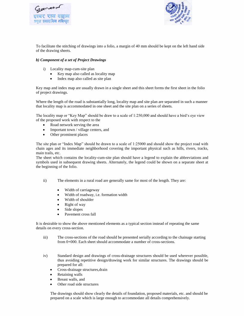
To facilitate the stitching of drawings into a folio, a margin of 40 mm should be kept on the left hand side of the drawing sheets.
b) Component of a set of Project Drawings
i) Locality map-cum-site plan
Key map also called as locality map
Index map also called as site plan
Key map and index map are usually drawn in a single sheet and this sheet forms the first sheet in the folio of project drawings.
Where the length of the road is substantially long, locality map and site plan are separated in such a manner that locality map is accommodated in one sheet and the site plan on a series of sheets.
The locality map or “Key Map” should be draw to a scale of 1:250,000 and should have a bird‘s eye view of the proposed work with respect to the
Road network serving the area
Important town / village centers, and
Other prominent places
The site plan or “Index Map” should be drawn to a scale of 1:25000 and should show the project road with chain ages and its immediate neighborhood covering the important physical such as hills, rivers, tracks,
main trails, etc. The sheet which contains the locality-cum-site plan should have a legend to explain the abbreviations and symbols used in subsequent drawing sheets. Alternately, the legend could be shown on a separate sheet at the beginning of the folio.
ii) The elements in a rural road are generally same for most of the length. They are:
Width of carriageway
Width of roadway, i.e. formation width
Width of shoulder
Right of way
Side slopes
Pavement cross fall
It is desirable to show the above mentioned elements as a typical section instead of repeating the same details on every cross-section.
iii) The cross-sections of the road should be presented serially according to the chainage starting
from 0+000. Each sheet should accommodate a number of cross-sections.
iv) Standard design and drawings of cross-drainage structures should be used wherever possible, thus avoiding repetitive design/drawing work for similar structures. The drawings should be prepared for all:
Cross-drainage structures,drain
Retaining walls
Breast walls, and
Other road side structures
The drawings should show clearly the details of foundation, proposed materials, etc. and should be prepared on a scale which is large enough to accommodate all details comprehensively.

1.2.5.4. Bill of Quantities
Bill of quantities of a project should cover all the required items listed in the cost estimate. All the details of
labor and materials should be given as a break-down under respective work item. In general, quantities of the work items and their units should be given in the approved format.
1.2.5.5. Schedules of Labor and Materials
Schedules of labor and materials are essential, in advance, for construction planning and management purposes.
1.3. Use of Computer and Design software
Consultants are encouraged to use computers and appropriate design software. The consultant should submit the soft (electronic) copy of reports of the total output of the works.
1.4. Liaison with engineer in-charge
The consultants are required to maintain close liaison with the Management Contractor and DTO Engineer. Draft design for alignment, earthwork and pavement design and other technical aspects of the design shall
be discussed with the Management Contractor and DTO Engineer for approval prior to proceeding with the final detailed design
1.5. Client’s Proposed Composition of Staff
a) Professionals: Team
Leader
Transportation/Highway /civil
engineer Highway/civil engineer (Design) Environmental Engineer
Geologist/Geo tech engineer
b) Support Staffs
Sub engineer/Surveyor
Auto CAD Operator
1.6. Qualification and Experience: a) Team Leader: The Team Leader will take the overall responsibility for the execution of the work in
accordance with the TOR and also for the co-ordination of all professional inputs.
He will be responsible to the Client. He will also maintain close contact with municipality of the
programme districts to ensure that the contract is implemented in accordance with the government's
policies and objects.
The team leader should have a Master degree in civil engineering and should preferably have a Master's
Degree in the field of Highway/Transportation. He should have 7 years of general experience in road sector
and 3 years in specific experience in similar nature of works as design/ construction supervision of road
improvement/upgrading/ rehabilitation projects.
b) Transportation/Highway Engineer:
should have wide experience and expertise in planning, detail engineering surveying, designing and construction of rural roads, including:
Must have completed masters’s Degree in Transportation Engineering. More than 3 years experience in planning, detail engineering survey, design and construction
supervision of rural roads in hilly districts
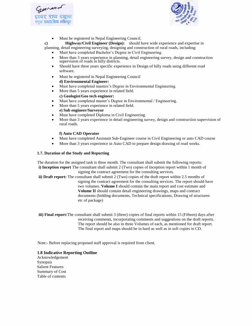
Must be registered in Nepal Engineering Council. c) Highway/Civil Engineer (Design): should have wide experience and expertise in planning, detail engineering surveying, designing and construction of rural roads, including:
Must have completed Bachelor’s Degree in Civil Engineering.
More than 3 years experience in planning, detail engineering survey, design and construction supervision of roads in hilly districts.
Should have three years specific experience in Design of hilly roads using different road
software.
Must be registered in Nepal Engineering Council d) Environmental Engineer:
Must have completed masters’s Degree in Environmental Engineering. More than 5 years experience in related field.
c) Geologist/Geo tech engineer:
Must have completed master’s Degree in Environmental / Engineering. More than 5 years experience in related field.
e) Sub engineer/Surveyor
Must have completed Diploma in Civil Engineering. More than 3 years experience in detail engineering survey, design and construction supervision of
rural roads.
f) Auto CAD Operator Must have completed Assistant Sub-Engineer course in Civil Engineering or auto CAD course
More than 3 years experience in Auto CAD to prepare design drawing of road works.
1.7. Duration of the Study and Reporting
The duration for the assigned task is three month. The consultant shall submit the following reports: i) Inception report The consultant shall submit 2 (Two) copies of Inception report within 1 month of
signing the contract agreement for the consulting services. ii) Draft report: The consultant shall submit 2 (Two) copies of the draft report within 2.5 months of
signing the contract agreement for the consulting services. The report should have
two volumes. Volume I should contain the main report and cost estimate and
Volume II should contain detail engineering drawings, maps and contract
documents (bidding documents, Technical specifications, Drawing of structures
etc of package)
iii) Final report:The consultant shall submit 3 (three) copies of final reports within 15 (Fifteen) days after
receiving comments, incorporating comments and suggestions on the draft reports. The report should be also in three Volumes of each, as mentioned for draft report.
The final report and maps should be in hard as well as in soft copies in CD.
Note:- Before replacing proposed staff approval is required from client.
1.8 Indicative Reporting Outline Acknowledgement Synopsis
Salient Features Summary of Cost
Table of contents
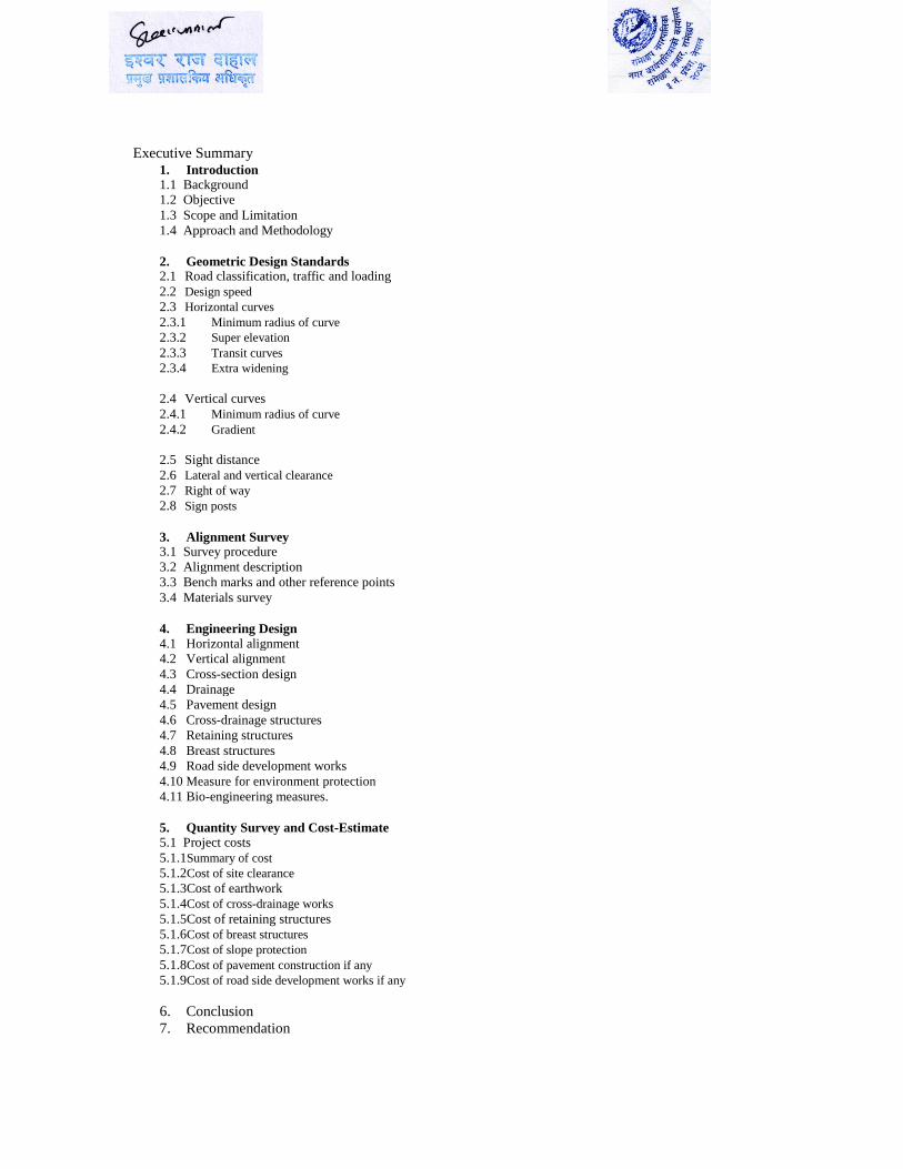
Executive Summary 1. Introduction 1. 1 Background 1. 2 Objective 1. 3 Scope and Limitation
1. 4 Approach and Methodology
2. Geometric Design Standards 2.1 Road classification, traffic and loading 2.2 Design speed 2.3 Horizontal curves 2.3.1 Minimum radius of curve 2.3.2 Super elevation 2.3.3 Transit curves 2.3.4 Extra widening
2.4 Vertical curves 2.4.1 Minimum radius of curve 2.4.2 Gradient
2.5 Sight distance 2.6 Lateral and vertical clearance 2.7 Right of way 2.8 Sign posts
3. Alignment Survey 3. 1 Survey procedure
3. 2 Alignment description
3. 3 Bench marks and other reference points 3. 4 Materials survey
4. Engineering Design
4.1 Horizontal alignment 4.2 Vertical alignment 4.3 Cross-section design 4.4 Drainage 4.5 Pavement design 4.6 Cross-drainage structures 4.7 Retaining structures 4.8 Breast structures 4.9 Road side development works 4.10 Measure for environment protection 4.11 Bio-engineering measures.
5. Quantity Survey and Cost-Estimate 5. 1 Project costs
5. 1.1Summary of cost
5. 1.2Cost of site clearance
5. 1.3Cost of earthwork
5. 1.4Cost of cross-drainage works 5. 1.5Cost of retaining structures
5. 1.6Cost of breast structures
5. 1.7Cost of slope protection
5. 1.8Cost of pavement construction if any 5. 1.9Cost of road side development works if any
6. Conclusion
7. Recommendation

1.9. Proposal Submission
The consultants shall submit technical and financial proposals under two-envelope system. The technical
and financial proposals must be enclosed in separate wax sealed envelopes, Then both the sealed envelopes must be enclosed in an outer waxed sealed envelope, clearly stating the name of proposal, purchaser’s
address and the firms' name and address.
1.10. Payment Schedule
The payment schedule will be as per the following:
After submission of inception report = 20% of the total contract amount.
After submission of the draft report = 30 % of the total contract amount. After submission and approval of the final report = 50% of the total contract amount.
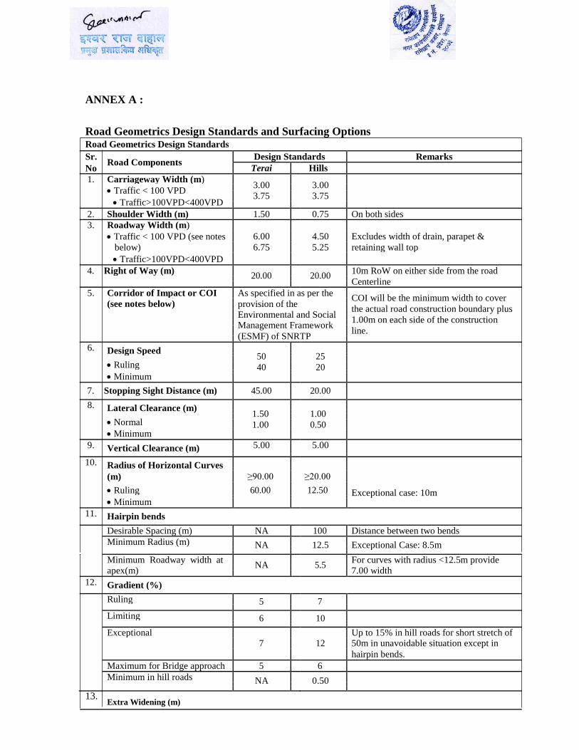
ANNEX A :
Road Geometrics Design Standards and Surfacing Options Road Geometrics Design Standards Sr.
Road Components Design Standards Remarks
No Terai
Hills
1. Carriageway Width (m) 3.00
3.00
Traffic < 100 VPD
3.75
3.75
Traffic>100VPD<400VPD
2. Shoulder Width (m) 1.50 0.75 On both sides
3. Roadway Width (m)
Traffic < 100 VPD (see notes 6.00 4.50 Excludes width of drain, parapet &
below) 6.75 5.25 retaining wall top
Traffic>100VPD<400VPD
4. Right of Way (m) 20.00
20.00
10m RoW on either side from the road
Centerline
5. Corridor of Impact or COI As specified in as per the COI will be the minimum width to cover
(see notes below) provision of the
the actual road construction boundary plus
Environmental and Social
1.00m on each side of the construction
Management Framework
line.
(ESMF) of SNRTP
6. Design Speed 50
25
Ruling
40 20
Minimum
7. Stopping Sight Distance (m) 45.00 20.00
8. Lateral Clearance (m) 1.50
1.00
Normal
1.00 0.50
Minimum
9. Vertical Clearance (m) 5.00 5.00
10. Radius of Horizontal Curves
(m) ≥90.00 ≥20.00
Ruling 60.00 12.50 Exceptional case: 10m
Minimum
11. Hairpin bends
Desirable Spacing (m) NA 100 Distance between two bends
Minimum Radius (m) NA 12.5 Exceptional Case: 8.5m
Minimum Roadway width at NA
5.5
For curves with radius <12.5m provide
apex(m)
7.00 width
12. Gradient (%)
Ruling 5 7
Limiting 6 10
Exceptional Up to 15% in hill roads for short stretch of
7 12 50m in unavoidable situation except in
hairpin bends.
Maximum for Bridge approach 5 6
Minimum in hill roads NA 0.50
13. Extra Widening (m)
For curve radius ≤ 20m 1.5 1.5
For curve radius 20 -60 m 0.60 0.60
For curve radius > 60 m Nil Nil
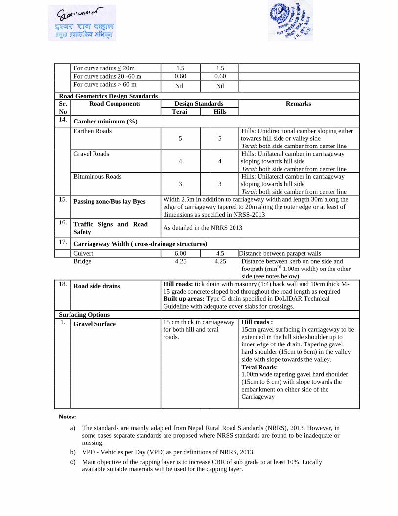
Road Geometrics Design Standards
Sr. Road Components Design Standards Remarks
No Terai Hills
14. Camber minimum (%)
Earthen Roads Hills: Unidirectional camber sloping either
5 5 towards hill side or valley side
Terai: both side camber from center line
Gravel Roads Hills: Unilateral camber in carriageway
4 4 sloping towards hill side
Terai: both side camber from center line
Bituminous Roads Hills: Unilateral camber in carriageway
3 3 sloping towards hill side
Terai: both side camber from center line
15. Passing zone/Bus lay Byes Width 2.5m in addition to carriageway width and length 30m along the
edge of carriageway tapered to 20m along the outer edge or at least of
dimensions as specified in NRSS-2013
16. Traffic Signs and Road As detailed in the NRRS 2013
Safety
17. Carriageway Width ( cross-drainage structures)
Culvert 6.00 4.5 Distance between parapet walls
Bridge 4.25 4.25 Distance between kerb on one side and
footpath (minm
1.00m width) on the other
side (see notes below)
18. Road side drains Hill roads: tick drain with masonry (1:4) back wall and 10cm thick M-
15 grade concrete sloped bed throughout the road length as required
Built up areas: Type G drain specified in DoLIDAR Technical
Guideline with adequate cover slabs for crossings.
Surfacing Options
1. Gravel Surface 15 cm thick in carriageway Hill roads :
for both hill and terai 15cm gravel surfacing in carriageway to be
roads. extended in the hill side shoulder up to
inner edge of the drain. Tapering gavel
hard shoulder (15cm to 6cm) in the valley
side with slope towards the valley.
Terai Roads:
1.00m wide tapering gavel hard shoulder
(15cm to 6 cm) with slope towards the
embankment on either side of the
Carriageway
Notes:
a) The standards are mainly adapted from Nepal Rural Road Standards (NRRS), 2013. However, in
some cases separate standards are proposed where NRSS standards are found to be inadequate or missing.
b) VPD - Vehicles per Day (VPD) as per definitions of NRRS, 2013.
c) Main objective of the capping layer is to increase CBR of sub grade to at least 10%. Locally
available suitable materials will be used for the capping layer.


![g]kfn ;/sf/ s]Gb|Lo cfof]hgf sfof{Gjog OsfO{mofald-clpiu.gov.np/public/kcfinder/upload/files/RS_Ramechhap.pdf48 140182 RS Kipa Sherpa Ramechhap Bamti 4 Garchha Umakund 2 49 140184](https://img.pdfslide.us/doc/110x75/5cd957a988c9930b098d1596/gkfn-sf-sgblo-cfofhgf-sfofgjog-osfomofald-clpiugovnppublickcfinderuploadfilesrs.jpg)


![s]Gb|Lo cfof]hgf sfof{Gjog OsfO{ - mofald-clpiu.gov.npmofald-clpiu.gov.np/public/kcfinder/upload/files/Ramechhap.pdf · 48 R-21-3-1-0-001 Dhawang Dolma Kama Ramechhap Bethan 1 464451](https://img.pdfslide.us/doc/110x75/5b085bbc7f8b9a992a8c26e0/sgblo-cfofhgf-sfofgjog-osfo-mofald-clpiugovnpmofald-clpiugovnppublickcfinderuploadfiles.jpg)